Embed Size (px)
Citation preview

National Aeronautics and GRC-CONN-DOC-5022 Rev A
Space Administration EFFECTIVE DATE: 04/26/2012
Space Communications and Navigation (SCaN) Testbed Project
National Aeronautics and Space Administration
John H. Glenn Research Center at Lewis Field, Ohio 44135
SCaN TESTBED PROJECT
SCaN Testbed Flight and Ground System
Description
AUTHORIZED by CM when under FORMAL Configuration Control
Date Signature
/s/ Robert E. Turk 05/01/2012
Distribution:
[ ] NASA (U.S. Gov. Only) [ ] Project Only [ X ] Government and Contractors
Availability:
[ X ] Public (No Restriction) [ ] Export Controlled [ ] Confidential/ Commercial [ ] Internal Use Only

Space Communications and Navigation (SCaN) Testbed Project
Title: SCaN Testbed Flight and Ground System Description Document No.: GRC-CONN-DOC-5022 Revision: A
Effective Date: 04/26/2012 Page ii of vi
PREFACE
National Aeronautics and Space Administration (NASA) is developing an on-orbit, adaptable,
Software Defined Radio (SDR)/Space Telecommunications Radio System (STRS)-based testbed
facility to conduct a suite of experiments to advance technologies, reduce risk, and enable future
mission capabilities on the International Space Station (ISS). The Space Communications and
Navigation (SCaN) Testbed Project will provide NASA, industry, other Government agencies,
and academic partners the opportunity to develop and field communications, navigation, and
networking technologies in the laboratory and space environment based on reconfigurable,
software defined radio platforms and the STRS Architecture. The project was previously known
as the Communications, Navigation, and Networking reConfigurable Testbed (CoNNeCT), Also
included are the required support efforts for Mission Integration and Operations, consisting of a
ground system and the Glenn Telescience Support Center (GRC TSC). This document has been
prepared in accordance with NASA Glenn’s Configuration Management Procedural
Requirements GLPR 8040.1 and applies to the SCaN Testbed configuration management
activities performed at NASA’s Glenn Research Center (GRC). This document is consistent
with the requirements of SSP 41170, Configuration Management Requirements, International
Space Station, and GLPR 7120.5.30 Space Assurance Requirements (SAR).
This document describes the functional operation of the SCaN Testbed and provides a top level
overview of information a prospective Experimenter will require in order to conduct experiments
using the SCaN Testbed. Also included is an overview of the Mission Operations Network to
provide the experimenter a holistic understanding to utilize the SCaN Testbed.

Space Communications and Navigation (SCaN) Testbed Project
Title: SCaN Testbed Flight and Ground System Description Document No.: GRC-CONN-DOC-5022 Revision: A
Effective Date: 04/26/2012 Page iii of vi
DOCUMENT HISTORY LOG
Status
(Preliminary/
Baseline/
Revision/
Canceled)
Document
Revision
Effective
Date Description
Baseline – 06/23/2011 Initial Release
Revision A 04/26/2012 Incorporated CONN-CR-0560. Updated document with more complete Ground Integration Unit and WSC SDR information.

Space Communications and Navigation (SCaN) Testbed Project
Title: SCaN Testbed Flight and Ground System Description Document No.: GRC-CONN-DOC-5022 Revision: A
Effective Date: 04/26/2012 Page iv of vi
SIGNATURE PAGE
Prepared By:
/s/ Charles Hall 04/27/2012
Scott R. Lawyer Date
QinetiQ North America Senior Engineer
NASA Glenn Research Center
Concurred By:
/s/ Steven Sinacore 04/30/2012
Steve Sinacore Date
SCaN Testbed Mission Operations Lead
NASA Glenn Research Center
/s/ Lynn Capadona 04/27/2012
Lynn Capadona Date
SCaN Testbed Deputy Chief Engineer
NASA Glenn Research Center
/s/ Richard Reinhart 04/30/2012
Richard Reinhart Date
SCaN Testbed Principal Investigator
NASA Glenn Research Center
Approved By:
/s/ Diane C. Malarik 04/27/2012
Diane C. Malarik Date
SCaN Testbed Project Manager
NASA Glenn Research Center

Space Communications and Navigation (SCaN) Testbed Project
Title: SCaN Testbed Flight and Ground System Description Document No.: GRC-CONN-DOC-5022 Revision: A
Effective Date: 04/26/2012 Page v of vi
TABLE OF CONTENTS
1.0 INTRODUCTION ...................................................................................................................1 1.1 Purpose .................................................................................................................... 1
1.2 Scope ....................................................................................................................... 1 2.0 DOCUMENTS .........................................................................................................................2
2.1 Applicable Documents ............................................................................................ 2 2.2 Reference Documents ............................................................................................. 3 2.3 Order of Precedence for Documents ....................................................................... 3
3.0 FLIGHT SYSTEM OVERVIEW ............................................................................................4 3.1 Avionics Subsystem ................................................................................................ 7 3.1.1 Commanding and Data ........................................................................................... 8 3.2 Radio Frequency Subsystem ................................................................................... 9
3.2.1 High Power Amplifier........................................................................................... 10 3.2.2 Coaxial Transfer Switches .................................................................................... 11
3.3 Antenna Pointing System ...................................................................................... 12 3.4 Software ................................................................................................................ 15 3.4.1 Avionics Subsystem Software .............................................................................. 16
3.4.2 Software Defined Radio Software ........................................................................ 16 3.5 Software Defined Radios ...................................................................................... 16
3.5.1 General Dynamics (GD) Software Defined Radio ............................................... 17 3.5.2 Jet Propulsion Laboratory (JPL) Software Defined Radio ................................... 17 3.5.3 Harris Corporation Software Defined Radio ........................................................ 18
3.5.4 White Sands Complex Software Defined Radio ................................................... 18 3.6 Experiment Operations ......................................................................................... 19
3.6.1 Waveforms ............................................................................................................ 20 3.6.2 Waveform Updates ............................................................................................... 20
3.7 Experimenter Data ................................................................................................ 23 4.0 MISSION OPERATIONS NETWORK OVERVIEW ..........................................................24
4.1 Primary Communication Path Elements ............................................................... 25 4.1.1 Huntsville Operations Support Center (HOSC)/Payload Operations Integration
Center (POIC) ...................................................................................................................... 25 4.2 Experiment Communication Path Elements ......................................................... 26
4.2.1 Tracking and Data Relay Satellite (TDRS) .......................................................... 26 4.2.2 White Sands Complex (WSC) .............................................................................. 26 4.2.2.1 Legacy Services .................................................................................................... 27 4.2.2.2 Non-Legacy Services ............................................................................................ 28 4.2.3 Wallops Ground Station (WGS)/Other Near Earth Networks (NEN) .................. 29
4.3 SCaN Testbed Control Center (STCC) ................................................................. 29 4.4 SCaN Testbed Experiment Center (STEC) ........................................................... 30
4.5 Ground Integration Unit (GIU) With Support Systems ........................................ 31 APPENDIX A ACRONYMS AND ABBREVIATIONS ...........................................................33
A.1 Scope ..................................................................................................................... 33 A.2 List of Acronyms and Abbreviations .................................................................... 33

Space Communications and Navigation (SCaN) Testbed Project
Title: SCaN Testbed Flight and Ground System Description Document No.: GRC-CONN-DOC-5022 Revision: A
Effective Date: 04/26/2012 Page vi of vi
TABLE OF FIGURES
Figure 3-1—SCaN Testbed System Overview ............................................................................... 4 Figure 3-2—SCaN Testbed Location on ISS.................................................................................. 5
Figure 3-3—SCaN Testbed Major Components Viewed from Ram/Zenith Angle (Stowed
Position Shown) ...................................................................................................................... 6 Figure 3-4—Avionics System Block Diagram ............................................................................... 8 Figure 3-5—Flight System Block Diagram .................................................................................... 9 Figure 3-6—S-band RF Path Definition - CTS Matrix Switch Positions ..................................... 11
Figure 3-7—Antenna Nadir Field-of-View .................................................................................. 13 Figure 3-8—Antenna Ram Field-of-View .................................................................................... 13 Figure 3-9—Antenna Starboard Field-of-View ............................................................................ 14 Figure 3-10—Antenna Starboard Ka Field-of-View .................................................................... 14
Figure 3-11—Antenna Zenith Field-of-View ............................................................................... 15 Figure 4-1—SCaN Testbed Ground System................................................................................. 24
Figure 4-2—SCaN WSC-SDR and Control PC at GRC .............................................................. 28 Figure 4-3—SCaN Testbed Control Center Functional Diagram................................................. 30 Figure 4-4—Experimenter Access Points ..................................................................................... 31
TABLE OF TABLES
Table 2-1—Applicable Documents ................................................................................................ 2 Table 2-2—Reference Documents .................................................................................................. 3
Table 3-1—S-band RF Path Definition - SDR to Antenna........................................................... 12 Table 3-2—L-band Waveform Parameters for JPL ...................................................................... 18 Table 3-3—Transmit Launch Waveforms .................................................................................... 21
Table 3-4—Receive Launch Waveforms...................................................................................... 22 Table A-1—Acronyms.................................................................................................................. 33
Space Communications and Navigation (SCaN) Testbed Project
Title: SCaN Testbed Flight and Ground System Description Document No.: GRC-CONN-DOC-5022 Revision: A
Effective Date: 04/26/2012 Page 1 of 35
1.0 INTRODUCTION
The Space Communications and Navigation (SCaN) Testbed Project will provide an on-orbit,
adaptable, Software Defined Radios (SDR) and STRS-based facility on the ISS to conduct a
suite of experiments to reduce risk and enable future mission capability. The SCaN Testbed
Experiments Program objective is to devise and conduct on-orbit experiments to
validate and advance the open architecture standard for SDRs; advance communication,
navigation, and network technologies to mitigate specific NASA mission risks and to enable
future mission capabilities.
1.1 Purpose
The purpose of this document is to describe the functional operation and capabilities of the SCaN
Testbed and identify top level information a prospective experimenter would require in order to
conduct experiments. Identified below are several research and technology areas the SCaN
Testbed was designed to support.
• Software defined radio TRL advancement
• SDR reconfiguration
• SDR-based S-band Communications
• SDR-based Ka-band Communications
• On-board data management function and payload networking
• SDR-based GPS Navigation
1.2 Scope
The scope of this document covers the SCaN Testbed and corresponding operational systems. It
provides a description of the system required for PI-led experimenters to propose experiments
using SCaN Testbed capabilities.

Space Communications and Navigation (SCaN) Testbed Project
Title: SCaN Testbed Flight and Ground System Description Document No.: GRC-CONN-DOC-5022 Revision: A
Effective Date: 04/26/2012 Page 2 of 35
2.0 DOCUMENTS
This section lists the NASA/Government and non-NASA/Government specifications, standards,
guidelines, handbooks, or other special publications applicable to the application of this
document. Access to Sensitive But Unclassified (SBU) controlled documents by
experimenters/SCaN Testbed users can be made available after experimenter utilization
approval. Sensitive but Unclassified is a NASA classification marking for proprietary or export
controlled documents and information.
2.1 Applicable Documents
Applicable documents are those documents that form a part of this document. These documents
carry the same weight as if they were stated within the body of this document.
Table 2-1—Applicable Documents
Document Number Applicable Document
GRC-CONN-OPS-0371 Ground Systems Description and GIU User’s Manual
Status: Baseline, Effective Date: 9/9/2011
GRC-CONN-ICD-0023
Volume 1
CoNNeCT/GD SDR Interface Control Document
Status: Baseline, Effective Date: 12/18/2009
GRC-CONN-ICD-0030
Volume 3
JPL STRS Operating Environment Data I/O Interface Desc. ICD
SBU, Status: Draft In Review, Revision: A, Issue Date: 10/18/2010
GRC-CONN-ICD-0030
Volume 5
JPL Baseline Proc Mod Boot Code Comm & Telemetry Dictionary
SBU, Status: Draft In Review, Revision: A, Issue Date: 10/18/2010
GRC-CONN-ICD-0090
Volume 1
CoNNeCT/Harris SDR Interface Control Document
Status: Baseline, Effective Date: 10/15/2009
NPR 7150.2A NASA Software Engineering Requirements
Revision A, Effective Date: 11/19/2009
NASA/TM—2010-216809 Space Telecommunications Radio System (STRS)
Architecture Standard
Space Communications and Navigation (SCaN) Testbed Project
Title: SCaN Testbed Flight and Ground System Description Document No.: GRC-CONN-DOC-5022 Revision: A
Effective Date: 04/26/2012 Page 3 of 35
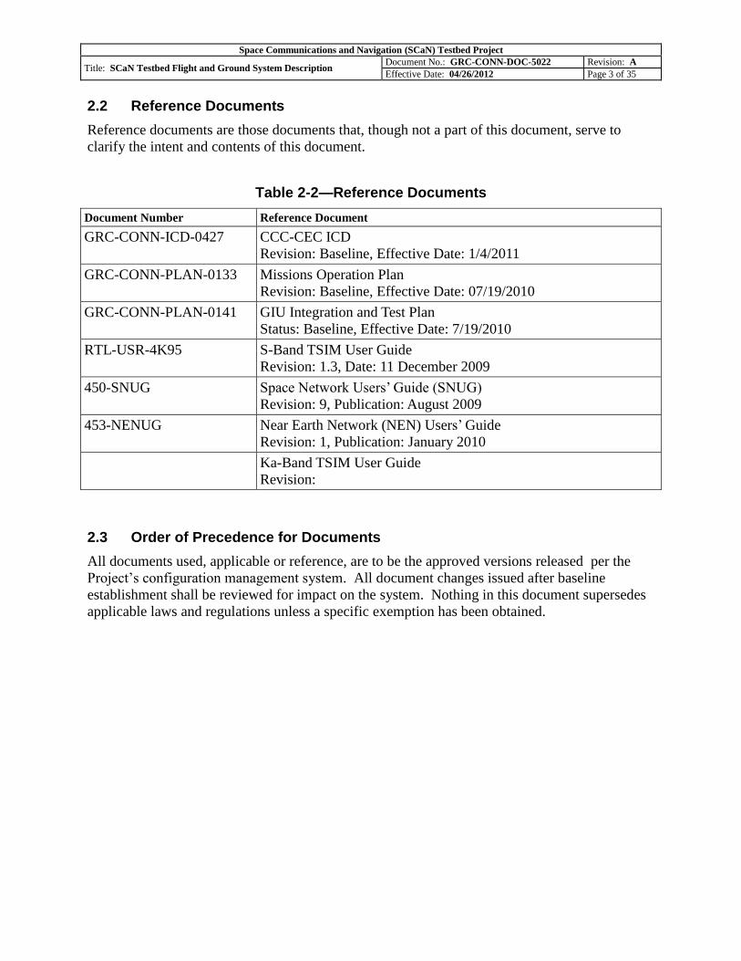
2.2 Reference Documents
Reference documents are those documents that, though not a part of this document, serve to
clarify the intent and contents of this document.
Table 2-2—Reference Documents
Document Number Reference Document
GRC-CONN-ICD-0427 CCC-CEC ICD
Revision: Baseline, Effective Date: 1/4/2011
GRC-CONN-PLAN-0133 Missions Operation Plan
Revision: Baseline, Effective Date: 07/19/2010
GRC-CONN-PLAN-0141 GIU Integration and Test Plan
Status: Baseline, Effective Date: 7/19/2010
RTL-USR-4K95 S-Band TSIM User Guide
Revision: 1.3, Date: 11 December 2009
450-SNUG Space Network Users’ Guide (SNUG)
Revision: 9, Publication: August 2009
453-NENUG Near Earth Network (NEN) Users’ Guide
Revision: 1, Publication: January 2010
Ka-Band TSIM User Guide
Revision:
2.3 Order of Precedence for Documents
All documents used, applicable or reference, are to be the approved versions released per the
Project’s configuration management system. All document changes issued after baseline
establishment shall be reviewed for impact on the system. Nothing in this document supersedes
applicable laws and regulations unless a specific exemption has been obtained.

Space Communications and Navigation (SCaN) Testbed Project
Title: SCaN Testbed Flight and Ground System Description Document No.: GRC-CONN-DOC-5022 Revision: A
Effective Date: 04/26/2012 Page 4 of 35
3.0 FLIGHT SYSTEM OVERVIEW
The SCaN Testbed Operations Project is comprised of a Flight System and a Ground System, an
overview is shown in Figure 3-1. The integrated flight system is commonly referred to as the
SCaN Testbed. It is resident on an ExPRESS Logistics Carrier (ELC) on an exterior truss of the
International Space Station (ISS). Figure 3-2 illustrates the location of the SCaN Testbed on the
ISS. The SCaN Testbed will launch aboard the Japanese H-II Transfer Vehicle (HTV) Multi-
Purpose Exposed Pallet (EPMP) to the ISS, and will be transferred to the Port side ExPRESS
Logistics Carrier (ELC) 3 via Extravehicular Robotics (EVR).
Figure 3-1—SCaN Testbed System Overview

Space Communications and Navigation (SCaN) Testbed Project
Title: SCaN Testbed Flight and Ground System Description Document No.: GRC-CONN-DOC-5022 Revision: A
Effective Date: 04/26/2012 Page 5 of 35
Figure 3-2—SCaN Testbed Location on ISS
The SCaN Testbed will consist of reconfigurable and reprogrammable Software Defined Radio
(SDR) transceivers/transponders operating at S-band, Ka-band, and L-band, along with the
required RF/antenna systems necessary for communications. Designed to operate for a
minimum of two years, the three SDRs will provide S-band duplex Radio Frequency (RF) links
directly with the ground, (also referred to as the Near Earth Network (NEN)), S-band duplex RF
links with the Tracking and Data Relay Satellite System (TDRSS), (also referred to as the Space
Network (SN)), Ka-Band duplex with TDRSS, and L-Band receive-only with the Global
Positioning Satellite System (GPSS). The SCaN Testbed will be in low earth orbit and has
multiple antennas providing connectivity to a series of NASA Space Network (SN) TDRSS
satellites in geosynchronous orbits and NASA Near Earth Network (NEN) stations. The major
components of the SCaN Testbed are shown in Figure 3-3.

Space Communications and Navigation (SCaN) Testbed Project
Title: SCaN Testbed Flight and Ground System Description Document No.: GRC-CONN-DOC-5022 Revision: A
Effective Date: 04/26/2012 Page 6 of 35
Figure 3-3—SCaN Testbed Major Components Viewed from Ram/Zenith Angle (Stowed Position Shown)
The SCaN Testbed system consists of a space-based flight system and a terrestrial-based ground
system. The SCaN Testbed system interfaces with external systems to send and receive RF
signals to and from space. These RF signals carry commands and data between the SCaN
Testbed elements. Both the SCaN Testbed flight system and ground system send and receive
commands, send and receive data, and manipulate (store, route, and process) data. The SCaN
Testbed system consists of four primary subsystems. The four primary subsystems are the SCaN
Testbed located on the Express Pallet on the ISS, the SCaN Testbed Support Equipment located
at various ground stations, the SCaN Testbed Control Center (STCC) and the SCaN Testbed
Ground Integration Unit with Support Systems both located at the Glenn Research Center.

Space Communications and Navigation (SCaN) Testbed Project
Title: SCaN Testbed Flight and Ground System Description Document No.: GRC-CONN-DOC-5022 Revision: A
Effective Date: 04/26/2012 Page 7 of 35
The SCaN Testbed uses a frequency assignment between ISS and TDRS at S-band and Ka-band
to send and receive data from the radios and antenna system. SCaN Testbed commands are sent
from the SCaN Testbed Control Center located within the GRC Tele-Science Support (TSC) to
the radios to configure and operate each radio. Communication with the SCaN Testbed through
ISS is considered the primary path, this includes the wired path between the SCaN Testbed and
ISS and the wireless path from ISS to the White Sands Complex (WSC). The WSC is wired to
the remaining ground station facilities consisting of the Huntsville Operations Center (HOSC),
the NASA Integrated Service Network (NISN) and the SCaN Testbed Control Center (STCC),
the SCaN Testbed Experiment Center (STEC) is also part of the STCC.
A RF data connection will provide a direct bi-directional connection between the radios and
ground stations. This second communication path (commanding and bidirectional data) is the
experimental link with the SN and the NEN, this is the wireless path between the SCaN Testbed
and Ground Stations such as the Wallops Ground Station. The TSC facility located at GRC
allows payload developers and scientists on earth to monitor and control experiments onboard
the International Space Station (ISS). Data from the radios are received at the White Sands
Complex, Las Cruces, NM via TDRS and routed to GRC. For Global Positioning System (GPS)
experiments, the JPL radio is configured to receive and process GPS signals. Data is collected
on-board and sent to ground via TDRS or the primary path.
3.1 Avionics Subsystem
The Avionics Subsystem provides the electrical and command & data handling interface between
ISS systems and the SCaN Testbed systems. These interfaces include power distribution and
control, grounding and isolation, communication (commanding and data) interfaces with ISS,
flight system health and status, and SCaN Testbed subsystem communications and control as
shown in Figure 3-4. In addition, the Avionics Package contains software that can be
reprogrammed on orbit to support experiment specific requirements. The Ground Support
Equipment (GSE) interface is for pre flight test only.

Space Communications and Navigation (SCaN) Testbed Project
Title: SCaN Testbed Flight and Ground System Description Document No.: GRC-CONN-DOC-5022 Revision: A
Effective Date: 04/26/2012 Page 8 of 35
Figure 3-4—Avionics System Block Diagram
3.1.1 Commanding and Data
The Avionics Subsystem interfaces with the SCaN Testbed subsystems through MIL-STD-1553
and Spacewire protocols; and with the ELC through dual redundant (A/B), RT MIL-STD-1553,
and 100 Base Ethernet in accordance with IEEE 8802-3 (Ethernet link for data flow from the
SCaN Testbed to the ELC only) protocols as shown in Figure 3-5. Each SDR has a command
and control interface and data communications interface. The GD and JPL SDRs use MIL-STD-
1553 for command and control and Spacewire for the data interface. The Harris SDR has two
separate Spacewire interfaces, one for command/control and one for data. The RF subsystem
Traveling Wave Tube Amplifier (TWTA) and coax switches are controlled through discrete
digital lines. The Antenna Pointing System Gimbal Control Electronics (GCE) also interfaces
with the avionics package for command and control through a MIL-STD-1553 interface.

Space Communications and Navigation (SCaN) Testbed Project
Title: SCaN Testbed Flight and Ground System Description Document No.: GRC-CONN-DOC-5022 Revision: A
Effective Date: 04/26/2012 Page 9 of 35
Figure 3-5—Flight System Block Diagram
3.2 Radio Frequency Subsystem
The Radio Frequency (RF) Subsystem is comprised of a Traveling Wave Tube Amplifier
(TWTA), Coaxial Transfer Switches, Antennas, Diplexers, an RF Isolator, an RF Attenuator, and
transmission lines to interconnect the RF Subsystem components with the radios. The RF
Subsystem radiates RF signals intended for TDRS and the ground; and receives RF signals from
TDRS, the ground, and the GPS system. The architecture of the SCaN Testbed has the ability to
send RF signals from two separate SDRs to two antennas simultaneously. The ability to send RF
signals from two separate SDRs to the same antenna or from a single radio to two different
antennas is not supported by the architecture and cannot happen due to switch positions required.
The RF Subsystem contains four active devices: the TWTA and three switches. All components
that comprise each of the three RF paths; Ka-band, S-band, and L-band are shown in Figure 3-5.
The RF Subsystem interfaces with the Avionics Subsystem, the Flight Enclosure, the Antenna
Pointing Subsystem, and the three Radios.
Space Communications and Navigation (SCaN) Testbed Project
Title: SCaN Testbed Flight and Ground System Description Document No.: GRC-CONN-DOC-5022 Revision: A
Effective Date: 04/26/2012 Page 10 of 35
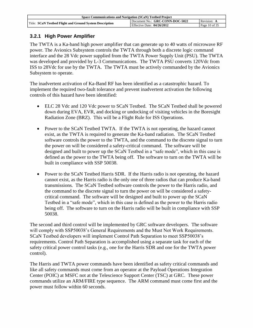
3.2.1 High Power Amplifier
The TWTA is a Ka-band high power amplifier that can generate up to 40 watts of microwave RF
power. The Avionics Subsystem controls the TWTA through both a discrete logic command
interface and the 28 Vdc power supplied from the TWTA Power Supply Unit (PSU). The TWTA
was developed and provided by L-3 Communications. The TWTA PSU converts 120Vdc from
ISS to 28Vdc for use by the TWTA. The TWTA must be actively commanded by the Avionics
Subsystem to operate.
The inadvertent activation of Ka-Band RF has been identified as a catastrophic hazard. To
implement the required two-fault tolerance and prevent inadvertent activation the following
controls of this hazard have been identified:
ELC 28 Vdc and 120 Vdc power to SCaN Testbed. The SCaN Testbed shall be powered
down during EVA, EVR, and docking or undocking of visiting vehicles in the Boresight
Radiation Zone (BRZ). This will be a Flight Rule for ISS Operations.
Power to the SCaN Testbed TWTA. If the TWTA is not operating, the hazard cannot
exist, as the TWTA is required to generate the Ka-band radiation. The SCaN Testbed
software controls the power to the TWTA, and the command to the discrete signal to turn
the power on will be considered a safety-critical command. The software will be
designed and built to power up the SCaN Testbed in a “safe mode”, which in this case is
defined as the power to the TWTA being off. The software to turn on the TWTA will be
built in compliance with SSP 50038.
Power to the SCaN Testbed Harris SDR. If the Harris radio is not operating, the hazard
cannot exist, as the Harris radio is the only one of three radios that can produce Ka-band
transmissions. The SCaN Testbed software controls the power to the Harris radio, and
the command to the discrete signal to turn the power on will be considered a safety-
critical command. The software will be designed and built to power up the SCaN
Testbed in a “safe mode”, which in this case is defined as the power to the Harris radio
being off. The software to turn on the Harris radio will be built in compliance with SSP
50038.
The second and third control will be implemented by GRC software developers. The software
will comply with SSP50038’s General Requirements and the Must Not Work Requirements.
SCaN Testbed developers will implement Control Path Separation to meet SSP50038’s
requirements. Control Path Separation is accomplished using a separate task for each of the
safety critical power control tasks (e.g., one for the Harris SDR and one for the TWTA power
control).
The Harris and TWTA power commands have been identified as safety critical commands and
like all safety commands must come from an operator at the Payload Operations Integration
Center (POIC) at MSFC not at the Telescience Support Center (TSC) at GRC. These power
commands utilize an ARM/FIRE type sequence. The ARM command must come first and the
power must follow within 60 seconds.
Space Communications and Navigation (SCaN) Testbed Project
Title: SCaN Testbed Flight and Ground System Description Document No.: GRC-CONN-DOC-5022 Revision: A
Effective Date: 04/26/2012 Page 11 of 35
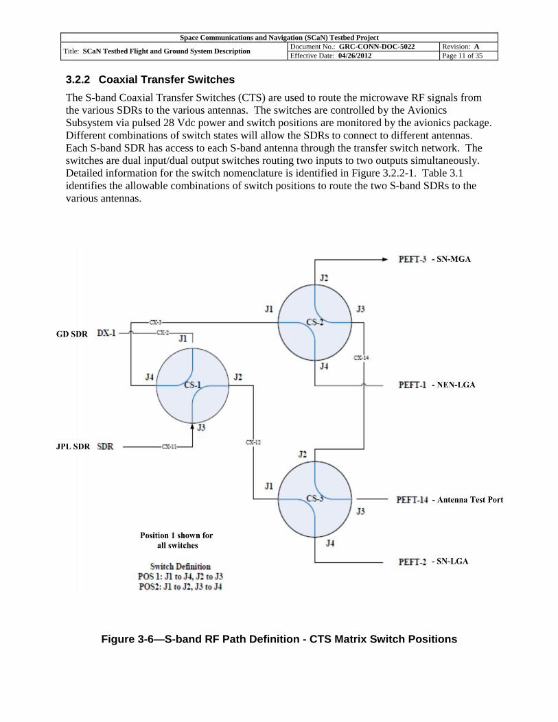
3.2.2 Coaxial Transfer Switches
The S-band Coaxial Transfer Switches (CTS) are used to route the microwave RF signals from
the various SDRs to the various antennas. The switches are controlled by the Avionics
Subsystem via pulsed 28 Vdc power and switch positions are monitored by the avionics package.
Different combinations of switch states will allow the SDRs to connect to different antennas.
Each S-band SDR has access to each S-band antenna through the transfer switch network. The
switches are dual input/dual output switches routing two inputs to two outputs simultaneously.
Detailed information for the switch nomenclature is identified in Figure 3.2.2-1. Table 3.1
identifies the allowable combinations of switch positions to route the two S-band SDRs to the
various antennas.
Figure 3-6—S-band RF Path Definition - CTS Matrix Switch Positions

Space Communications and Navigation (SCaN) Testbed Project
Title: SCaN Testbed Flight and Ground System Description Document No.: GRC-CONN-DOC-5022 Revision: A
Effective Date: 04/26/2012 Page 12 of 35
Table 3-1—S-band RF Path Definition - SDR to Antenna
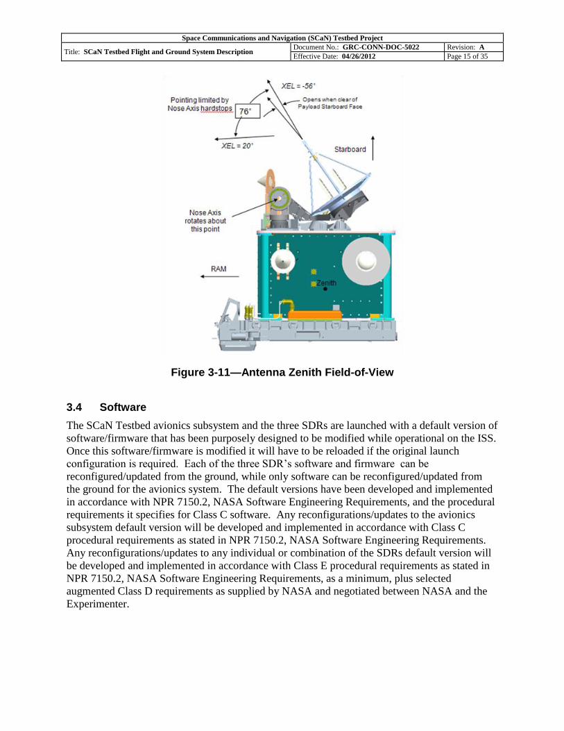
3.3 Antenna Pointing System
The Antenna Pointing Subsystem (APS) moves the S-Band Medium Gain Antenna and the Ka-
Band High Gain Antenna in two rotary axes to track TDRS satellites from the ELC3 location on
ISS. The gimbaled antennas are locked for launch and deployed on-orbit. The SCaN Testbed
Flight System antenna Field-of-View characteristics are shown in Figures 3.3-1 through 3.3-5.

Space Communications and Navigation (SCaN) Testbed Project
Title: SCaN Testbed Flight and Ground System Description Document No.: GRC-CONN-DOC-5022 Revision: A
Effective Date: 04/26/2012 Page 13 of 35
Figure 3-7—Antenna Nadir Field-of-View
Figure 3-8—Antenna Ram Field-of-View

Space Communications and Navigation (SCaN) Testbed Project
Title: SCaN Testbed Flight and Ground System Description Document No.: GRC-CONN-DOC-5022 Revision: A
Effective Date: 04/26/2012 Page 14 of 35
Figure 3-9—Antenna Starboard Field-of-View
Figure 3-10—Antenna Starboard Ka Field-of-View
Space Communications and Navigation (SCaN) Testbed Project
Title: SCaN Testbed Flight and Ground System Description Document No.: GRC-CONN-DOC-5022 Revision: A
Effective Date: 04/26/2012 Page 15 of 35
Figure 3-11—Antenna Zenith Field-of-View
3.4 Software
The SCaN Testbed avionics subsystem and the three SDRs are launched with a default version of
software/firmware that has been purposely designed to be modified while operational on the ISS.
Once this software/firmware is modified it will have to be reloaded if the original launch
configuration is required. Each of the three SDR’s software and firmware can be
reconfigured/updated from the ground, while only software can be reconfigured/updated from
the ground for the avionics system. The default versions have been developed and implemented
in accordance with NPR 7150.2, NASA Software Engineering Requirements, and the procedural
requirements it specifies for Class C software. Any reconfigurations/updates to the avionics
subsystem default version will be developed and implemented in accordance with Class C
procedural requirements as stated in NPR 7150.2, NASA Software Engineering Requirements.
Any reconfigurations/updates to any individual or combination of the SDRs default version will
be developed and implemented in accordance with Class E procedural requirements as stated in
NPR 7150.2, NASA Software Engineering Requirements, as a minimum, plus selected
augmented Class D requirements as supplied by NASA and negotiated between NASA and the
Experimenter.

Space Communications and Navigation (SCaN) Testbed Project
Title: SCaN Testbed Flight and Ground System Description Document No.: GRC-CONN-DOC-5022 Revision: A
Effective Date: 04/26/2012 Page 16 of 35
3.4.1 Avionics Subsystem Software
The avionics infrastructure software runs on a single-board computer to process commands,
provide thermal monitoring and control, communicate with the radios and ISS, command and
configure the radios, control RF subsystem switching, command the APS, collect sensor data,
send telemetry to the ground, and perform data and file management. Infrastructure software
development and subsequent revisions for the Avionic subsystem is the responsibility of the
Project. Experimenters may also run software on the avionics for experiments. Experimenter
software might include such functions as network routing among radios using IP or DTN
protocols, data simulation from a stored file, collection of data received by a radio or other
application. Experimenter software running on the avionics will be integrated by the Project in
conjunction with the experimenter’s support.
3.4.2 Software Defined Radio Software
Each of the three Software Defined Radios has an Operating Environment (OE), which includes
an operating system and provides infrastructure services to applications and waveforms in
accordance with the Space Telecommunications Radio System Standard (STRS). In
addition to the OE, each SDR runs waveform applications which implement the unique
capabilities of the radio to receive and transmit radio frequency (RF) signals. The OE is the
STRS architecture standard middleware that abstracts the SDR hardware from the waveform
application software (i.e. general purpose processor code and Field Programmable Gate Array
(FPGA) configuration data). Each SDR has an OE which acts as an operating system to process
commands, interact with hardware, and configure the SDR. All three OEs comply with the STRS
Standard. Each SDR must run waveforms which implement the capability of the radio and
generate the RF signal that will be transmitted.
OE updates, if needed, will generally be developed by the Project in partnership with the SDR
platform developer. Waveform applications will be developed and provided by experimenters
for operation on the individual SDRs.
3.5 Software Defined Radios
At the core of the Flight System are three unique software defined radios (SDRs) provided by
government and industry partners. In general, an SDR system is a radio in which some or all of
the physical-layer and higher layer functions are implemented in software and/or firmware. In a
generic SDR, the signal received at the antenna is amplified by a low-noise amplifier and then
immediately digitized by an analog to digital converter, processed by the software functionality
of the SDR’s digital processing, and exits the SDR in a digital baseband form. Conversely,
digital baseband data entering the SDR is processed by the software functionality of the SDR’s
digital processing, converted to an analog RF signal by a digital to analog converter, and
amplified by a high-power amplifier before being transmitted through the antenna. The SCaN
Testbed has three separate SDR systems. In addition to the capabilities identified below, all
radios are capable of support networking, navigation, time transfer, file management, and data
analysis.

Space Communications and Navigation (SCaN) Testbed Project
Title: SCaN Testbed Flight and Ground System Description Document No.: GRC-CONN-DOC-5022 Revision: A
Effective Date: 04/26/2012 Page 17 of 35
The JPL provided SDR leverages off the developments of the Electra radio. This SDR is
capable of full-duplex, TDRSS-compatible, STRS-compliant S-band communications
and receive-only GPS L-band navigation.
The Harris Corporation provided SDR was developed under a cooperative agreement
with GRC. This SDR is capable of full-duplex, TDRSS-compatible, STRS-compliant Ka-
band communications.
The General Dynamics (GD) provided SDR was developed under a cooperative
agreement with GRC. This radio leverages developments of the TDRSS fourth-
generation transponder and is capable of full-duplex, TDRSS-compatible, STRS
compliant S-band communications.
The radios are mounted to the Flight Enclosure and functionally interface with the Avionics and
RF systems as shown in Figure 3-5. Note certain capability configurations enable multiple SDR
use for networking and/or routing experiments.
3.5.1 General Dynamics (GD) Software Defined Radio
The GD radio will utilize S-band for forward and return links to TDRSS or direct links to a
ground station, this radio is a reprogrammable S-band transceiver designed for space use. The
delivered SDR is compliant with the STRS architecture. The S-band SDR operates at two
unique frequency pairs for operation with the multiple access service of TDRSS or the single
access service of TDRSS. Either frequency can be used for the direct to ground link. Each
operating frequency provides a 6 MHz wide RF link for use by the experimenter waveform
application. The GD SDR contains Actel RTAX and Xilinx QPRO Virtex II Field Programmable
Gate Arrays (FPGA), a ColdFire micro processor, and utilizes Verilog and Very high speed
integrated circuits Hardware Description Language (VHDL) Hardware Description Languages.
3.5.2 Jet Propulsion Laboratory (JPL) Software Defined Radio
The JPL radio utilizes S-band for forward and return links to TDRSS or direct links to a ground
station. The JPL SDR also receives GPS frequencies of L1, L2, and L5 as shown in Table 3.2.
This radio is a reprogrammable S-band transceiver designed for space use. The delivered SDR is
compliant with the STRS architecture. The JPL S-band SDR operates at any frequency in the
2.025-2.120 Rx band and 2.2-2.3 Tx band. The waveform loaded at launch uses two discrete
frequencies and works with the multiple access service of TDRSS or the single access service of
TDRSS. Either frequency of the launch waveform can also be used for the direct to ground link.
The JPL radio has an 11 MHz receive bandwidth available for experimenter waveform
applications while the launch waveform uses a 6 MHz receive channel. The JPL transmitter has
a 16 MHz bandwidth available to experimenters, however the current regulatory approval is for
two 6 MHz channels at S-Band. The use of other transmit frequencies within the capabilities of
the radio would require National Telecommunications and Information Administration (NTIA)
approval. The JPL SDR contains Actel RTAX 2000 and Xilinx FPGAs, an Actel 697 with
SPARC processor, RF converter section, and a nominally 10W power amplifier (approximately
7.5 Watts after losses).

Space Communications and Navigation (SCaN) Testbed Project
Title: SCaN Testbed Flight and Ground System Description Document No.: GRC-CONN-DOC-5022 Revision: A
Effective Date: 04/26/2012 Page 18 of 35
Table 3-2—L-band Waveform Parameters for JPL
GPS Signal Description Frequency Reference
L1 C/A Code 1575.42 MHz
IS-GPS revision D
L2 Civil Code 1227.60 MHz
L5 1176.45 MHz IS-GPS-705
3.5.3 Harris Corporation Software Defined Radio
The Harris radio will utilize the TDRSS Ka-band service. This radio is a reprogrammable Ka-
band transceiver designed for space use and the delivered SDR is compliant with the STRS
architecture. The Ka-band SDR operates at a unique Ka-band frequency pair for operation with
the single access Ka-band service of TDRSS. The Ka-band SDR provides a 225 MHz wide RF
link for use by the experimenter waveform application. The Harris SDR contains Xilinx Vertex-
4 FPGAs, an AITech 950 single board computer utilizing the VxWorks Operating System, and
an S-band to Ka-band RF converter.
3.5.4 White Sands Complex Software Defined Radio
The White Sands Complex Software Defined Radio (WSC-SDR) will be located at the Space
Network’s White Sands Complex to provide a reprogrammable ground radio for experiments.
The WSC-SDR is designed to facilitate waveform implementation for SCaN Testbed
experimenters beyond TDRSS legacy waveforms. Given the unknown nature of SCaN Testbed
experiments, the WSC-SDR will focus on providing a generic signal processing capability. The
WSC-SDR will be a platform for SCaN Testbed experimenters to create a matched modulator
and demodulator for the waveforms loaded onto SCaN Testbed’s space segment.
The WSC-SDR contains the FPGA, CPU, and GPU resources sufficient to demodulate and
decode a waveform transmitted from the Harris radio that includes high-order modulation and
LDPC encoding on the 225 MHz KaSAR service or the 6 MHz S/MA and SSA return service by
interfacing with the Space Network’s 225 MHz IF service. It is also capable of encoding and
modulating data for the S- and Ka-band forward service, once the Space Network makes the
service available. The WSC-SDR will provide a digital signal processing (DSP) capability
through the combination of field-programmable gate arrays, multiple multi-core central
processing units, and one or more graphical processing units. Experimenters will access these
hardware capabilities by utilizing VHDL and higher-level software to implement their unique
designs. A similar SDR will also be available as part of the GRC Supporting Systems for
experiment development and test.
Space Communications and Navigation (SCaN) Testbed Project
Title: SCaN Testbed Flight and Ground System Description Document No.: GRC-CONN-DOC-5022 Revision: A
Effective Date: 04/26/2012 Page 19 of 35
As summarized above the WSC-SDR is designed to provide a generic signal processing
capability to SCaN Testbed experiments. The radio will reside in the same rack as the SCaN
Testbed WSGT Front-End Processor (FEP). The radio will provide a bi-directional RF interface
compatible with WSC’s 370 MHz SSA and KaSA IF services. Experimental data will be
returned to the SCaN Testbed ground system at GRC via a TCP network connection over the
SCaN Testbed VPN. A second network interface will provide control of the WSC-SDR and
system health and status telemetry during operation. The WSC-SDR will also accept 10 MHz, 1
pulse-per-second (PPS), and IRIG-B references from the WSC Common Time and Frequency
System (CTFS).
3.6 Experiment Operations
After the initial checkout and commissioning, the communications experiments will examine the
operational paradigm-shift of using the flexibility offered by SDR for space communications and
navigation. Experiments will be conducted using the capabilities of the radio such as
communications and navigation waveforms and applications. These investigations will use the
frequency bands S-band, L-band for GPS, and Ka-band. GPS reception will focus initially on the
L1 signals and future L2 and L5 signals during the operations stage as they become available.
Parameters such as availability, integrity, and performance will be evaluated. Networking
capability is envisioned as part of the payload design. Ka-band experiments will include high
rate communications, tracking, and pointing and channel characterization. The SCaN Testbed is
intended to be reconfigured from the ground with new software and firmware. Applications and
waveform parameters such as forward error correction codes (e.g., low density parity check,
block codes, Reed Solomon), adaptive power control, signal (pre)distortion (e.g., filtering),
acquisition, and timing signals/parameters will be varied. SDR assessments will include Single
Event Upset (SEU) fault mitigation and software reliability studies. The radios and waveforms
will be compliant with the STRS architecture. The lessons learned from utilizing STRS will be
the basis for updating the standard in the future, likewise, updated architecture implementations
can be investigated.
Some experiments may involve modifying SDR waveforms or payload controller applications.
These new applications and/or waveforms, once verified on the ground, will require reliable file
transfer to the target elements of the SCaN Testbed on-board system. Once installed, a sequence
of pre-defined events will demonstrate the new capabilities. SCaN Testbed experiments will fall
into five general categories: advancing STRS/SDR technology, advanced communication
concepts, on-orbit networking technology, and next generation navigation techniques.
SCaN Testbed performance data will be collected and assessed over the life of the project.
Comparisons will be made with archived ground unit verification and previous on-orbit
performance to assess overall system health, determine sustaining engineering priorities, assist
with anomaly resolution, and support experiment operations.
Space Communications and Navigation (SCaN) Testbed Project
Title: SCaN Testbed Flight and Ground System Description Document No.: GRC-CONN-DOC-5022 Revision: A
Effective Date: 04/26/2012 Page 20 of 35
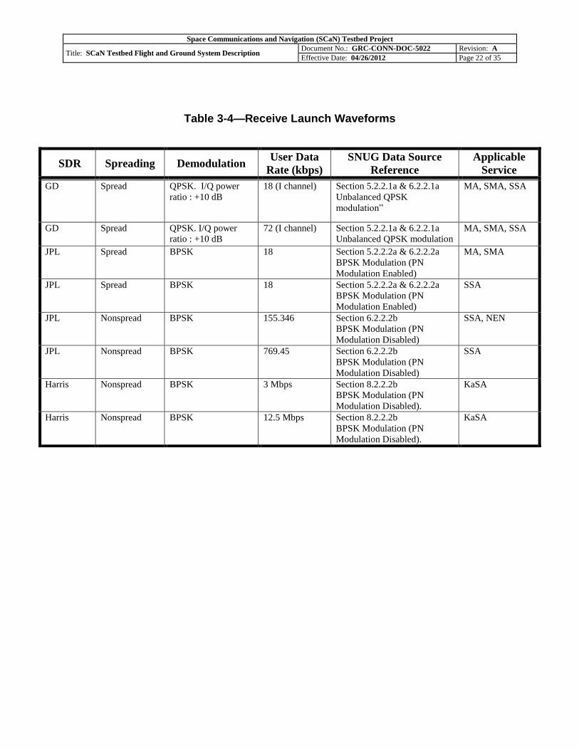
3.6.1 Waveforms
Waveform software and firmware defines functionality for most of the SDRs. STRS defines
standards for SDRs to maximize waveform firmware and software reuse and reduce porting
effort between various radios. All three SCaN Testbed radios will be launched with baseline
STRS-compliant waveforms. A sample of the baseline waveforms provided and used by the
Mission PI Team and in-house experiment team are provided in Tables 3.3 and 3.4.
SDRs consider a waveform much more than just the over-the-air electromagnetic signal. A
SDR waveform encompasses all of the processing that occurs to take user data to and from the
over-the-air signal. The waveform is an application running on the SDR. SCaN Testbed
waveforms will be run on the three radios using their specific hardware devices, however, all
three SDRs will have processor based software and FPGA-based firmware that implements the
waveform processing functions.
The SCaN Testbed is intended to have waveforms uploaded to the radios to replace or
complement the initial waveforms.
3.6.2 Waveform Updates
New waveforms and operational environment software will be developed on a SCaN Testbed
development system and verified in the SCaN Testbed Ground Integration Unit (GIU) prior to
being uploaded to the SCaN Testbed from the SCaN Testbed Control Center (STCC). The GIU
is used for proof-of-concept development, evaluation, testing, and verification of SDR waveform
experiments and avionics software upgrades. The GIU also includes the essential elements
needed to develop Flight Operating Procedures, train Ground Operations Personnel, and perform
flight anomaly resolution. The GIU with support systems consists of the GIU, an ExPRESS
Logistics Carrier (ELC) Simulator (ELC-Sim), a Telescience Resource Kit (TReK) Workstation,
TDRSS Simulators (T-Sim), a Near Earth Network Simulator (NEN-Sim), a Global Positioning
Satellite Simulator (GPS-Sim), a WSC-SDR, and Ground Support Equipment (GSE). GSE is
comprised of spectrum analyzers, power meters, power supplies, personal computers, and other
general test equipment. The GIU includes SDR Engineering Models and an Avionics Package
flight spare unit. The GIU also includes a TWTA, Gimbal Control Electronics (GCE), an
Interconnect Harness, Temperature Sensors, an Antenna Pointing System (APS), Gimbals, an RF
System custom version, and additional support equipment.
Verification on the GIU will include development of procedures and ground performance
characterization as insurance to safeguard the payload. This verification will culminate in an
experiment operational readiness review prior to scheduling use with the SCaN Testbed. The
STCC mission operations team will then either have the software and firmware uploaded prior to
the experiment period or upload the new software and firmware with the experiment co-located
in the SCaN Testbed Experiment Center (STEC), as the experiment plan prescribes.
The required links for the waveform verification depend on the waveform itself, and may
include the TDRSS S/MA, SSA, and Ka-band systems; the Near Earth Network; or GPS.

Space Communications and Navigation (SCaN) Testbed Project
Title: SCaN Testbed Flight and Ground System Description Document No.: GRC-CONN-DOC-5022 Revision: A
Effective Date: 04/26/2012 Page 21 of 35
The SDRs can perform physical layer functions, and have the payload controller/data manager
perform the higher layer functions or the SDR can perform many of the high level functions
within the SDR itself. Part of the science and technology objectives are to investigate having the
radio take on more functionality of the communication system. As the experiment period
progresses, higher layer functionality and some control functions are expected to be incorporated
into the SDRs to demonstrate the potential advantages of expanding the capabilities of the radios.
This will involve loading new waveforms onto the radios and removing functionality from the
payload controller/data manager service.
Table 3-3—Transmit Launch Waveforms
SDR TDRSS
Mode Modulation
User Data
Rate (kbps)
SNUG Data Source
Reference
Applicable
Service
GD S-band DG1,
Mode 1
SQPN I/Q
Power Ratio –
1:1
24 B3.2.1a Balanced Power Single
Data Source – Identical Data on
the I and Q channels.
I DR = Q DR = source DR
MA, SMA,
SSA
GD S-band DG1,
Mode 1
SQPN I/Q
Power Ratio –
1:1
192 B3.2.1b Balanced Power Single
Source Data – Alternate I/Q Bits
I DR = Q DR = ½ source DR
SMA, SSA
GD S-band DG1,
Mode 2
SQPN 24 B3.2.1a Balanced Power Single
Data Source – Identical Data on
the I and Q channels.
MA, SMA,
SSA
GD S-band DG1,
Mode 2
SQPN 192 B3.2.1b Balanced Power Single
Source Data – Alternate I/Q Bits
SMA, SSA
GD S-band DG1,
Mode 3
QPSK I/Q
power ratio –
1:4.
Q: 1000
I: 1 kbps
B3.2.1f Unbalanced Power
Dual Data Sources
SMA, SSA
GD S-band DG2 SQPSK I/Q
power ratio 1:1
1000 B3.3.1a Balanced Power Single
Data Source – Alternate I/Q bits
SMA, SSA,
NEN
JPL S-band DG1,
Mode 2
SS-BPSK 24 B3.2.1d DG1 Configurations.
Single Data Source with Single
Data Channel
MA, SMA
JPL S-band DG1,
Mode 2
SS-BPSK 24 B3.2.1d DG1 Configurations.
Single Data Source with Single
Data Channel
SSA
JPL S-band DG2 BPSK 192.362 B3.3.1c DG2 Configurations.
Single Data Source with Single
Data Channel
SSA
JPL S-band DG2 BPSK 769.45 B3.3.1c DG2 Configurations.
Single Data Source with Single
Data Channel
SSA, NEN
Harris Ka-band DG2 SQPSK I/Q
power ratio 1:1
12.5 Mbps B3.3.1a Balanced Power Single
Data Source – Alternate I/Q bits
I DR = Q DR = ½ source DR
KaSA
Harris Ka-band DG2 SQPSK I/Q
power ratio 1:1
100 Mbps
B3.3.1a Balanced Power Single
Data Source – Alternate I/Q bits
KaSA
Space Communications and Navigation (SCaN) Testbed Project
Title: SCaN Testbed Flight and Ground System Description Document No.: GRC-CONN-DOC-5022 Revision: A
Effective Date: 04/26/2012 Page 22 of 35
Table 3-4—Receive Launch Waveforms
SDR Spreading Demodulation User Data
Rate (kbps)
SNUG Data Source
Reference
Applicable
Service
GD Spread QPSK. I/Q power
ratio : +10 dB
18 (I channel) Section 5.2.2.1a & 6.2.2.1a
Unbalanced QPSK
modulation”
MA, SMA, SSA
GD Spread QPSK. I/Q power
ratio : +10 dB
72 (I channel) Section 5.2.2.1a & 6.2.2.1a
Unbalanced QPSK modulation
MA, SMA, SSA
JPL Spread BPSK 18 Section 5.2.2.2a & 6.2.2.2a
BPSK Modulation (PN
Modulation Enabled)
MA, SMA
JPL Spread BPSK 18 Section 5.2.2.2a & 6.2.2.2a
BPSK Modulation (PN
Modulation Enabled)
SSA
JPL Nonspread BPSK 155.346 Section 6.2.2.2b
BPSK Modulation (PN
Modulation Disabled)
SSA, NEN
JPL Nonspread BPSK 769.45 Section 6.2.2.2b
BPSK Modulation (PN
Modulation Disabled)
SSA
Harris Nonspread BPSK 3 Mbps Section 8.2.2.2b
BPSK Modulation (PN
Modulation Disabled).
KaSA
Harris Nonspread BPSK 12.5 Mbps Section 8.2.2.2b
BPSK Modulation (PN
Modulation Disabled).
KaSA
Space Communications and Navigation (SCaN) Testbed Project
Title: SCaN Testbed Flight and Ground System Description Document No.: GRC-CONN-DOC-5022 Revision: A
Effective Date: 04/26/2012 Page 23 of 35
3.7 Experimenter Data
Telemetry information generated by the SDRs, flight avionics, and the antenna/gimbal are
gathered by the PAS and sent to the STCC through the primary link. This data is displayed on
TReK workstations both in the STEC and STCC. A partial set of the telemetry items can be
displayed on the TReK workstation, in predesigned displays for each subsystem. Another option
for viewing telemetry is the Ad Hoc displays with which the experimenters can customize the
telemetry they view, for each subsystem. Log files can be created from the Ad Hoc screens and
are saved to the TReK workstation. Mission Operations personnel will not be normally logging
telemetry using the Ad Hoc displays in the STCC. Experimenters can log telemetry of interest
using Ad Hoc displays on the STEC TReK workstation.
Raw experiment data is the unprocessed return-link experiment data received by the STCC over
the experiment link after the NISN network overhead has been removed. Essentially this data is
the same as the demodulated and decoded return-link experiment data at White Sands.
For data returned over the SN, the raw experiment data is stored temporarily in the WSC SFEP
while being transmitted real-time to the experiment hardware for processing. After the pass, the
copy of the raw data is transferred from the WSC SFEP directly to the STCC SFEP storage
server. The data is then deleted from the WSC SFEP due to its limited storage capacity. Data
processed using launch waveforms and downlinked over the NEN, is not received real-time but
captured by WGS and then retrieved by Mission Operations from the WGS server, within that
shift. The stored raw experiment data, transmitted over either network, can be used to rerun
experiments in a playback configuration. The data is stored on the SFEP storage server for 6
months.
PI’s will be responsible for timely dissemination of experiment results and data publication. PIs
will be expected to support NASA organized workshops and conferences such as SCaN Testbed
Experimenters Conferences and ISS Utilization Conferences and present their findings.

Space Communications and Navigation (SCaN) Testbed Project
Title: SCaN Testbed Flight and Ground System Description Document No.: GRC-CONN-DOC-5022 Revision: A
Effective Date: 04/26/2012 Page 24 of 35
4.0 MISSION OPERATIONS NETWORK OVERVIEW
The Ground System consists of the SCaN Testbed Control Center (STCC), the SCaN Testbed
Experiment Center (STEC), the Ground Integration Unit (GIU), and the external ground systems
and their interfaces located at the Huntsville Operations Support Center (HOSC), White Sands
Complex (WSC), and Wallops Ground Station (WGS). The NASA Integrated Services Network
(NISN) is the network that connects these entities. Other ground stations beyond WGS may also
be used during operations, including White Sands 1, or user supplied ground stations. However,
WGS is currently the baseline station and was used for operations planning and link analysis.
The SCaN Testbed and Ground System send and receive commands and data, and manipulate
(stores, routes, and processes) data. The Flight System and Ground System interface with
external systems to send and receive RF signals to and from space. The RF signals carry
commands and data between the two SCaN Testbed elements. The Ground System provides
terrestrial control of the Flight System through the SCaN Testbed Control Center, a top-level
schematic of the Ground System is shown in Figure 4-1.
Figure 4-1—SCaN Testbed Ground System
Payload
Operations
Integration Center
(POIC)
White Sands
Complex
(WSC)
Wallops Ground
Station (WGS)
or other
Ground Station
NASA Glenn Research Center
GRC Building 333
Ground Verification Facility
GRC Telescience Support Center
CoNNeCT
Control
Center
CoNNeCT
Experiment
Center
Command
Telemetry
Health and Status
Voice
Video
Experimental data
Voice
Experimental data
Voice
SCAN
Testbed Flight
System
GPS
nLGAzLGA
MGA
HGA
Ground
Integration
Unit
Experimental
data
TDRS
TDRSSCaN Testbed Experiment Center
SCaN Testbed Control Center

Space Communications and Navigation (SCaN) Testbed Project
Title: SCaN Testbed Flight and Ground System Description Document No.: GRC-CONN-DOC-5022 Revision: A
Effective Date: 04/26/2012 Page 25 of 35
4.1 Primary Communication Path Elements
There are two communication paths for the SCaN Testbed mission. The primary
communications path (commanding and telemetry) will exist through the ISS S-band and Ku-
band links. This link will be coordinated through the Marshall Space Flight Center (MSFC)
Huntsville Operations Science Center (HOSC). The HOSC will receive the data from the SN and
forward it to the Glenn Research Center (GRC) SCaN Testbed Control Center (STCC) through
existing architecture.
The SCaN Testbed uses both the primary and experimental paths for commanding. Nominal
commanding will use the primary path. Commands will originate from the GRC TSC except for
13 critical commands. The critical commands will be sent by the Payload Rack Officer (PRO)
from the HOSC. The critical commands will reside only in the Payload Operations Integration
Center (POIC) database. In the future the SCaN Testbed will have the capability to use its RF
links to send non-critical commands through the SDRs to the Avionics. The TSC also contains
the Telescience Resource Kit (TReK) - a suite of PC-based software applications to monitor and
control payloads on-board the ISS. The TReK hosts a SCaN Testbed-specific Telemetry and
Acquisition Display System (CTADS) to display telemetry data from the SCaN Testbed and
configure commands for transmission. The primary path will be the baseline path for sending
new software to the SCaN Testbed and receiving telemetry and flight system stored data.
4.1.1 Huntsville Operations Support Center (HOSC)/Payload Operations Integration Center (POIC)
The Payload Operations Integration Center (POIC), located within MSFC's Huntsville
Operations Support Center (HOSC), houses the ground systems for managing the execution of
on-orbit International Space Station (ISS) payload operations including telemetry, command,
voice, video, information management, data reduction, and payload planning systems. All POIC
ground systems are distributed to the STCC.
The POIC contains several data and network systems that provide various capabilities:
The Payload Data Services System (PDSS) is used to receive, process, store (for 2 years),
and distribute International Space Station (ISS) 150 Mbps Payload telemetry data to the
POIC, International Partners, Telescience Support Centers and other remote user
facilities.
The Enhanced Huntsville Operations Support Center (EHOSC) performs command processing
and real-time and near real-time telemetry processing for simulation, training, and flight
operations.
The Payload Planning System (PPS) provides a set of software tools to automate the
planning, scheduling, and integration on ISS payload operations during pre-increment
planning, weekly planning, and real-time operations execution.

Space Communications and Navigation (SCaN) Testbed Project
Title: SCaN Testbed Flight and Ground System Description Document No.: GRC-CONN-DOC-5022 Revision: A
Effective Date: 04/26/2012 Page 26 of 35
4.2 Experiment Communication Path Elements
The second communication path (commanding and bidirectional data) is the experimental link
with the SN and the NEN. This link will be scheduled directly by the STCC with the supporting
elements. This link includes S-band and Ka-band services to the Space Network and S-band to
the NEN. Users will coordinate their ground station use with the STCC.
Forward Link: GRC STCC through NISN to White Sands to TDRSS to SCaN Testbed.
Return Link: SCaN Testbed to TDRSS to White Sands through NASA Integrated
Services Network NISN to GRC STCC.
Uplink: GRC STCC through NISN to Ground Station (e.g. WFF) to SCaN Testbed.
Downlink: SCaN Testbed to Ground Station (e.g. WFF) through NISN to GRC STCC.
4.2.1 Tracking and Data Relay Satellite (TDRS)
The SCaN Testbed located on the ISS will communicate with WSC ground stations via TDRS
satellites using Ka-band and S-band. The Tracking and Data Relay Satellite System (TDRSS) is
used by NASA and other United States government agencies for communications to and from
independent "User Platforms" such as the SCaN Testbed on the ISS. Full details of the TDRSS
are contained in the Space Network Users Guide (SNUG).
4.2.2 White Sands Complex (WSC)
The White Sands Complex (WSC) consists of two highly automated functionally identical
ground terminals. The White Sands Ground Terminal Upgrade also known as Cacique, and the
Second TDRSS Ground Terminal also known as Danzante, provide a relay interface between
the space segment, the ground segment and the other ground elements such as the HOSC.
The WSC, or TDRSS ground segment, includes the transmit and receive equipment to support
the four types of available customer satellite communications services: Multiple Access (S/MA),
Ku-Band Single Access (KuSA), Ka-Band Single Access (KaSA), and S-Band Single Access
(SSA). The SN can provide customer platform tracking and clock calibration services for S/MA,
SSA (including cross-support), and KuSA telecommunications services. The SN does not
provide tracking or clock calibration services for KaSA customers. TDRSS provides either two-
way range, two way doppler, or one-way doppler measurements. Sampled range and doppler
data are routed from the WSC to the GSFC Flight Dynamics Facility for orbit determination.
During initial launch and commissioning the three SDRs will be loaded with Space Network
User’s Guide (SNUG) compatible waveforms. Hardware checkout and validation will be carried
out with existing ground based receivers located at the White Sands Complex (WSC) TDRSS
terminal and WGS NEN ground stations. SCaN Testbed experiments that require unique
software and mission operations will have access to a SDR at the WSC separate from the legacy
services. A SDR capable of modulating and demodulating the experimental waveforms loaded
into the SCaN Testbed will be integrated into the White Sands Complex prior to the experiment
operations phase.

Space Communications and Navigation (SCaN) Testbed Project
Title: SCaN Testbed Flight and Ground System Description Document No.: GRC-CONN-DOC-5022 Revision: A
Effective Date: 04/26/2012 Page 27 of 35
4.2.2.1 Legacy Services
Several types of telecommunications services are simultaneously available to customers. The
type of telecommunications service selected is determined by the data rate required, duration of
service period, and customer platform telecommunications system design. The two primary
telecommunications services are termed Multiple Access (MA) and Single Access (SA). The SA
services are available at S-band, Ku-band, and Ka-band (F8-F10 only) frequencies. Legacy
services consist of the following and are further described in the SNUG. Note that the legacy Ku
band services are listed as a reference only. The SDRs do not have Ku band capabilities.
The SN can provide any of the following services:
A forward service, defined as the communication path that generally originates at the
customer control center and is routed through WSC to the TDRS to the customer
platform.
A return service, defined as the communication path that generally originates at the
customer platform and is routed through the TDRS to WSC back to the customer control
center and/or data acquisition location.
Both forward and return services simultaneously.
MA (also referred to as S-band Multiple Access (SMA) for TDRS F8-F10) forward and return
services operate at fixed S-band frequencies (nominally 2106.4 MHz forward and 2287.5 MHz
return) and polarization (Left Hand Circular). Forward service operations are time-shared among
TDRS customers where one customer is supported per TDRS at a time.
SA services available through each TDRS SA antenna are: S-band Single Access Forward, S-
band Single Access Return, Ku-band Single Access Forward, Ku-band Single Access Reverse,
Ka-band Single Access Forward (F8-F10 only), and Ka-band Single Access Reverse (F8-F10
only). Each TDRS SA antenna has one polarizer (either Left Hand Circular or Right Hand
Circular) for each frequency band (S, Ku, or Ka). The forward and return polarization for each
band must be the same in order to obtain simultaneous forward and return services through the
same SA antenna.
The SN can simultaneously support S-band and K-band (either Ku-band or Ka-band (F8-F10
only)) forward and/or return services through one SA antenna to the same ephemeris. TDRS F8-
F10 cannot simultaneously support Ku-band and Ka-band services through one SA antenna.
TDRSS S-band Single Access (SSA) services include forward and return telecommunications
services, and tracking services. SSA return service includes service through the SN receive
equipment and an automated IF service, where SN IF services are available to customers on a
case-by-case basis, IF service requires the customer to provide the receiver equipment and the
SN only provides the signal at the IF.

Space Communications and Navigation (SCaN) Testbed Project
Title: SCaN Testbed Flight and Ground System Description Document No.: GRC-CONN-DOC-5022 Revision: A
Effective Date: 04/26/2012 Page 28 of 35
TDRSS Ka-band Single Access (KaSA) services include forward and return telecommunications
services. KaSA Return service includes 225 MHz service through the SN receive equipment and
IF service for the KaSA 225 MHz and KaSA 650 MHz channels, where the 225 MHz IF is not
automated, but is being considered for automation and the 650 MHz service has been automated.
Additionally, SN IF services are available to customers on a case-by-case basis, IF service
requires the customer to provide the receiver equipment and the SN only provides the signal at
the IF. Tracking services are not provided via KaSA.
4.2.2.2 Non-Legacy Services
Non TDRSS SNUG compliant waveforms will require additional equipment at WSC to process
waveforms not currently supported by the SN. A ground based SDR will be designed and built
to facilitate waveform implementation for SCaN Testbed experimenters beyond TDRSS legacy
waveforms. The SDR will have two primary interfaces, an RF interface and an IP interface. The
RF interface will be connected to the WSC IF service. The IP interface will be connected to the
SCaN Testbed Virtual Private Network (VPN). The SCaN Testbed VPN connects equipment at
WSC to the STCC at GRC via IP. Currently a Front-End Processor (FEP) will be located at both
WSC and the STCC. The FEP converts IP encapsulated data to ECL/422 clock and data
bidirectionally and then sends it to/receives it from the experimenter equipment. The FEP exists
to allow legacy WSC equipment (with clock and data interfaces) to receive and transmit data to
the STCC over IP on the SCaN Testbed VPN. The SDR will exchange packetized link data with
the GRC FEP, allowing data to flow over the GRC FEP’s ECL interface to the STCC.
A control computer for the SDR at WSC will reside at the STCC. This PC will also reside on the
SCaN Testbed VPN, and will be exclusively used for the control and monitoring of the SDR at
WSC as shown in Figure 4-2.
Figure 4-2—SCaN WSC-SDR and Control PC at GRC
Space Communications and Navigation (SCaN) Testbed Project
Title: SCaN Testbed Flight and Ground System Description Document No.: GRC-CONN-DOC-5022 Revision: A
Effective Date: 04/26/2012 Page 29 of 35
4.2.3 Wallops Ground Station (WGS)/Other Near Earth Networks (NEN)
The SCaN Testbed can communicate directly with ground stations such as WGS or other ground
stations over S-band. Experimenter equipment connected to the ground stations will be used for
the ground experiment node. For experimenters using WGS, a NISN connection between the
STCC and WGS is available to route data to the STEC.
4.3 SCaN Testbed Control Center (STCC)
The STCC is the Mission Operations SCaN Testbed Control Center. It will reside within the
Telescience Support Center (TSC). The TSC facility located at GRC allows payload developers
and scientists on earth to monitor and control experiments onboard the International Space
Station (ISS). Data from the radios are received at WSC via TDRS and routed to GRC. The
STCC will make use of the existing TSC interfaces to the HOSC. The STCC will use the TSC
data network, which is an isolated network from the GRC campus network. Internet access to
external sites will also be available via a separate network, both for scheduling and other
interfaces such as the remote data access server.
The STCC will provide command and telemetry processing, experiment
demonstration/execution, experiment data archiving, and health and status data archiving. The
suite of data will be provided to approved users. The STCC will also interface with the Ground
Integration unit (GIU) for on-orbit anomaly resolution and waveform and Flight System software
verification prior to on-orbit upload. The GIU is a high fidelity duplicate of the flight SCaN
Testbed. The STCC diagram is shown in Figure 4-2.

Space Communications and Navigation (SCaN) Testbed Project
Title: SCaN Testbed Flight and Ground System Description Document No.: GRC-CONN-DOC-5022 Revision: A
Effective Date: 04/26/2012 Page 30 of 35
Figure 4-3—SCaN Testbed Control Center Functional Diagram
The existing TSC infrastructure includes command, data, voice loop, and video connections to
the MSFC Huntsville Operations Support Center (HOSC). Interfaces through the NASA
Integrated Services Network (NISN) to the Space Network (SN) and Near Earth Network (NEN)
will support the evaluation of the on-orbit radio performance. A web server will host data for
approved remote researchers.
4.4 SCaN Testbed Experiment Center (STEC)
The SCaN Testbed Experiment Center is the real time mission data analysis and interface for the
experimenter team. It is physically adjacent to the STCC and located within the TSC. It is
separate from the STCC because it is an experimental data center while the STCC is the overall
operations center. The physical location is necessary because of the proximity of experiment
supplied equipment to the STCC and the desire to analyze and make adjustments real-time
during experimental data link connections with TDRS or a ground station. Future experimenters
may be required to provide additional support equipment depending on what is needed and what
is available. The interface is governed by the CCC-CEC ICD, GRC-CONN-ICD-0427.
Near Earth
Network (WGS)
SCaN Testbed Control Center

Space Communications and Navigation (SCaN) Testbed Project
Title: SCaN Testbed Flight and Ground System Description Document No.: GRC-CONN-DOC-5022 Revision: A
Effective Date: 04/26/2012 Page 31 of 35
4.5 Ground Integration Unit (GIU) With Support Systems
The GIU with Support Systems (GIUSS) consists of the GIU, Antenna Pointing System (APS)
Rack, Test Equipment Interface (TEI) Racks #1 and #2, Power Acquisition System (PAS), two
S-Band TDRSS Simulators (TSIM), Ka-Band TSIM and Data Acquisition System and
Experiment Front End Processor (EFEP), ELC Suitcase Simulator (SCS), Telescience Resource
Kit (TReK) Workstation, WSC-SDR and GPS antenna. GSE is comprised of spectrum
analyzers, power meters, power supplies, personal computers, and other general test equipment.
The GIU includes SDR Engineering Models (EM) and an Avionics System (AS) spare Flight
Model (FM). The GIU also includes two Travelling Wave Tube Amplifiers (TWTA) EM,
Gimbal Control Electronics (GCE) EM, an Interconnect Harness EM, Temperature Sensors EM,
an Antenna Pointing System (APS) EM, Gimbals EM, an RF System EM/FM/SE custom
version, and additional Support Equipment (SE).
Experimenters can develop experiments by adding software/firmware and/or hardware in various
places within the SCaN Testbed System illustrated in Figure 4-3. Each cloud represents locations
where functions may be provided by experimenters within the system. Software/firmware can
be installed and operated on the orbiting system on the software defined radios and/or avionics.
On the ground, software/firmware can be installed and operated on the SDR at the White Sands
Complex which is connected to the WSC IF service. Experimenters may also provide unique
experiment hardware at either a Direct To Earth (DTE) station, or at the SCaN Testbed
Experiment Center. Hardware at the STEC may send and receive directly with the data stream to
the flight SDRs (via WSC) through the SCaN Testbed Control Center interface.
Figure 4-4—Experimenter Access Points
ISSCONNECT Flight System
Experiment
InterfaceExternal SystemsGround
System
SDR
Av
ion
ics
Experiment
Processor
CCC
NISN
WSCIF
WSCLegacy
Service
SDR
T
D
R
S
SR
F
S-band
DTESDR
= Experiment Element
STCC

Space Communications and Navigation (SCaN) Testbed Project
Title: SCaN Testbed Flight and Ground System Description Document No.: GRC-CONN-DOC-5022 Revision: A
Effective Date: 04/26/2012 Page 32 of 35
The Ground Integration Unit (GIU) will be utilized by experimenters for the following initial
experiment development activities.
Develop Avionics Software
Develop Ground Software
Develop an Operating Environment (OE) for a given radio
Develop Waveforms for the radios
Develop the On-Orbit Operating Procedures for Experiments
The GIU will support final experiment formal verification and validation consisting of the
following.
Avionics Software
Ground Software
Operating Environment (OE) for the radios
Waveforms for the radios
On-Orbit Operating Procedures for Experiments
The GIU will function as a tool to debug On-Orbit issues encountered on the Flight System.

Space Communications and Navigation (SCaN) Testbed Project
Title: SCaN Testbed Flight and Ground System Description Document No.: GRC-CONN-DOC-5022 Revision: A
Effective Date: 04/26/2012 Page 33 of 35
APPENDIX A ACRONYMS AND ABBREVIATIONS
A.1 Scope
This appendix lists the acronyms and abbreviations used in this document.
A.2 List of Acronyms and Abbreviations
Table A-1—Acronyms
Acronym Definition AFRAM Active - Flight Releasable Attachment Mechanism APS Antenna Pointing System AS Avionics System
BPSK Binary Phase-Shift Keying STCC SCaN Testbed Control Center STEC SCaN Testbed Experiment Center CM Configuration Management Comm Communication CONN CoNNeCT CoNNeCT Communications, Navigation, and Networking reConfigurable Testbed CPU Central Processing Unit
CTADS CoNNeCT Telemetry and Acquisition Display System
CTFS Common Time and Frequency System
CTS Coaxial Transfer Switch D/A Digital to Analog D/C Downconvert DSP Digital Signal Processing
DTE Direct To Earth DTN Delay Tolerant Networking EDS Experiment Development System EFEP Experiment Front End Processor
EHOSC Enhanced Huntsville Operations Support Center ELC Express Logistics Carrier EM Engineering Model EPMP Multi-Purpose Exposed Pallet EVA Extravehicular Activity EVR Extravehicular Robotics ExPA ExPRESS Pallet Adapter ExPRESS Expedite the Processing of Experiments to the Space Station Expt Experiment FEP Front End Processor
FM Frequency Modulation
FPGA Field-Programmable Gate Array FRAM Flight Releasable Attachment Mechanism GB Gigabyte GCE Gimbal Control Electronics GD General Dynamics GHz Gigahertz GIU Ground Integration Unit GIUSS Ground Integration Unit with Support Systems
GLPR NASA Glenn’s Configuration Management Procedural Requirement

Space Communications and Navigation (SCaN) Testbed Project
Title: SCaN Testbed Flight and Ground System Description Document No.: GRC-CONN-DOC-5022 Revision: A
Effective Date: 04/26/2012 Page 34 of 35
Gov Government
GPS Global Positioning System
GPU Ground Processor Unit
GRC Glenn Research Center
GSE Ground Support Equipment GSFC Goddard Space Flight Center HC Harris Corporation HOSC Huntsville Operations Support Center HTV H-II Transfer Vehicle I/O Input and Output ICD Interface Control Document IEEE Institute of Electrical and Electronic Engineers IF Intermediate Frequency IP Internet Protocol
IRIG-B Inter-Range Instrumentation Group - Time Code Format B
ISS International Space Station
ITS Integrated Truss Segment
JPL Jet Propulsion Laboratory
Ka-band 26.5 to 40 GHz KaSA Ka-band Single Access
KaSAR Ka-band Single Access Return
L-band 1 to 2 GHz LDPC Low Density Parity Check
LEO Low Earth Orbit LNA Low Noise Amplifier MA Multiple Access MHz Megahertz NASA National Aeronautics and Space Administration NEN Near Earth Network NISN NASA Integrated Services Network NTIA National Telecommunications and Information Administration OE Operating Environment Ops Operations PAS Power Acquisition System
PC Personal Computer
PDSS Payload Data Services System PI Principal Investigator
POIC Payload Operations Integration Center
PPS Pulses Per Second or Payload Planning System
PS Project Scientist
PSU Power Supply Unit QPSK Quadrature Phase-Shift Keying RF Radio Frequency RT Remote Terminal SA Single Access SAR Space Assurance and Requirements S-band 2 to 4 GHz SBIR Small Business Innovation Research SBU Sensitive But Unclassified SCaN Space Communications and Navigation SCS Suitcase Simulator
SDR Software Defined Radio
SDS Software Development System
SE Support Equipment
SEU Single Event Upset

Space Communications and Navigation (SCaN) Testbed Project
Title: SCaN Testbed Flight and Ground System Description Document No.: GRC-CONN-DOC-5022 Revision: A
Effective Date: 04/26/2012 Page 35 of 35
SMA S-band Multiple Access
SN Space Network
SNUG Space Network Users Guide
SQPN Staggered Quadrature Phase
SQPSK Staggered Quadrature Phase-Shift Keying SRD System Requirements Document SSA S-band Single Access
SSP Space Station Program
STRS Space Telecommunications Radio System
SW Software TCP Transmission Control Protocol
TDRS Tracking and Data Relay Satellite
TDRSS Tracking and Data Relay Satellite System
TEI Test Equipment Interface
TReK Telescience Resource Kit
TSC Telescience Support Center TRL Technology Readiness Level TSIM TDRSS Simulator TWTA Traveling Wave Tube Amplifier U/C Upconvert VDC Volts Direct Current VHDL Very high speed integrated circuits Hardware Description Language VPN Virtual Private Network
WF Waveform WFF Wallops Flight Facility WGS Wallops Ground Station
WSC White Sands Complex WSGT White Sands Ground Terminal


![McCormick - Aerodynamics, Aeronautics and Flight Mechanics [Partial Scan p1-179]](https://img.pdfslide.us/doc/110x75/547664afb4af9fbd568b45a6/mccormick-aerodynamics-aeronautics-and-flight-mechanics-partial-scan-p1-179-55845dba1f6f2.jpg)