Embed Size (px)
Citation preview
Abstract- Brushless DC machines (BLDC), Permanent Magnet Synchronous Machines (PMSM), Stepping Motors and Brushed DC machines (BDC) usage is ubiquitous in the power range below 1,5kW. There is a lot of common knowledge on these technologies. Stepping Motors are ideally suited for open loop positioning, BLDC machines are the most obvious candidate for high-speed applications, etc. However, literature lacks comprehensive research comparing these machines over a large range of applications. In this paper, more than 100 motors are considered. Their characteristics are compared and presented in a comprehensive way. These results support the common knowledge concerning the field of application of each technology and new insights follow from this quantitative comparison.
I. INTRODUCTION Within the power range up to 1500W, machine constructors
often doubt between different motor technologies for their drivetrains. In this paper, a range of properties of the machines in Table I are considered and compared to each other in order to back up the choice between motor technologies with concrete numbers. Before comparing these technologies based on data in section III, a summary of the common knowledge and operating principles of these machines is given in section II.
Table I: Machines considered in this study Motor technology Number of
machines Number of suppliers
Brushed DC 23 2 BLDC 21 2 PMSM 26 2
Stepping Motor 34 3
II. OPERATING PRINCIPLES
A. Brushed DC machines In Brushed DC machines the rotor field position is adapted by
means of brushes. This results in the simplest machine from a user’s perspective as providing a constant DC voltage is enough to drive the motor. When permanent magnets are used to generate the stator field, a compact construction is possible [1]. On the other hand, the brushes used for commutation reduce the robustness [2]. Due to wear of the commutator or the brushes, the lifetime of these motors is limited [3]. This is the major drawback of this technology. Driving a Brushed DC machine in its simplest form is depicted in red in Fig. Figure 2. Position and speed control (depicted in grey in Fig. Figure 2) is possible if some kind of position feedback is available.
Figure 1: Operating principle of a permanent magnet Brushed DC machine
Figure 2: Position control of a Brushed DC Machine
B. Brushless DC machines For Brushless DC machines (BLDC) the rotor is equipped
with permanent magnets but the stator field position should be changed over discrete positions to generate torque as depicted in Fig. 3. Consequently, optimal current wave form as depicted in Fig. 4 takes the form of square waves. Even at high speeds this current waveform is not demanding for current controllers. Together with these current waveforms the absence of brushes means the BLDC motor is the best candidate for high speed applications [4]. Therefore, these motors are mostly used for continuous operation in compressor, pump and ventilation systems [4]–[6].
On the other hand, position feedback is necessary to determine the optimal commutation of the current. However, this feedback can take the form of discrete and rather cheap Hall sensor signals.
Driving a Brushless DC machine (BLDC) in its simplest form
is depicted colored in Fig. Figure 6. As indicated a drive and position feedback are minimum requirements to drive a BLDC motor. In commercial drives speed control in the higher speed range is often already possible using the available Hall sensors [7]. For position control and speed control at lower speeds more accurate position feedback is necessary.
N
S
Brushed DCMachine
i*Speedcontrol
Positioncontrol
θ∗ n∗
+ +_ _Current
controllerEnc.v
A quantitative comparison between BLDC, PMSM, Brushed DC and Stepping Motor Technologies
Stijn Derammelaere1, Michiel Haemers1, Jasper De Viaene1, Florian Verbelen1, Kurt Stockman1
1 Department of Industrial System and Product Design, Ghent University campus Kortrijk, Belgium E-mail: [email protected]
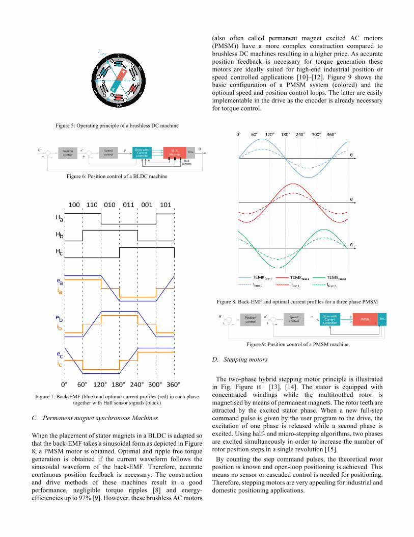
Figure 5: Operating principle of a brushless DC machine
Figure 6: Position control of a BLDC machine
Figure 7: Back-EMF (blue) and optimal current profiles (red) in each phase
together with Hall sensor signals (black)
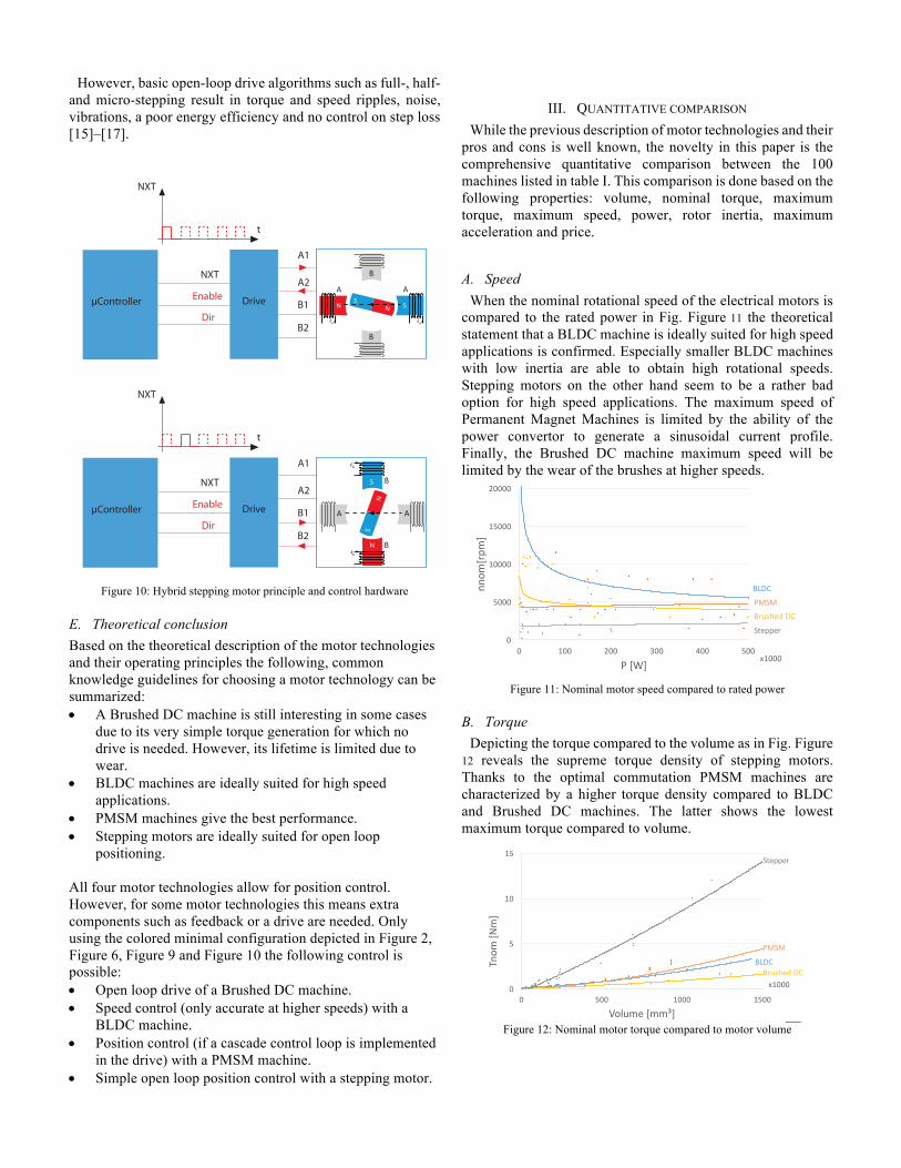
C. Permanent magnet synchronous Machines When the placement of stator magnets in a BLDC is adapted so that the back-EMF takes a sinusoidal form as depicted in Figure 8, a PMSM motor is obtained. Optimal and ripple free torque generation is obtained if the current waveform follows the sinusoidal waveform of the back-EMF. Therefore, accurate continuous position feedback is necessary. The construction and drive methods of these machines result in a good performance, negligible torque ripples [8] and energy-efficiencies up to 97% [9]. However, these brushless AC motors
(also often called permanent magnet excited AC motors (PMSM)) have a more complex construction compared to brushless DC machines resulting in a higher price. As accurate position feedback is necessary for torque generation these motors are ideally suited for high-end industrial position or speed controlled applications [10]–[12]. Figure 9 shows the basic configuration of a PMSM system (colored) and the optional speed and position control loops. The latter are easily implementable in the drive as the encoder is already necessary for torque control.
Figure 8: Back-EMF and optimal current profiles for a three phase PMSM
Figure 9: Position control of a PMSM machine
D. Stepping motors The two-phase hybrid stepping motor principle is illustrated
in Fig. Figure 10 [13], [14]. The stator is equipped with concentrated windings while the multitoothed rotor is magnetised by means of permanent magnets. The rotor teeth are attracted by the excited stator phase. When a new full-step command pulse is given by the user program to the drive, the excitation of one phase is released while a second phase is excited. Using half- and micro-stepping algorithms, two phases are excited simultaneously in order to increase the number of rotor position steps in a single revolution [15].
By counting the step command pulses, the theoretical rotor position is known and open-loop positioning is achieved. This means no sensor or cascaded control is needed for positioning. Therefore, stepping motors are very appealing for industrial and domestic positioning applications.
BLDCMachine
θi*Speedcontrol
Positioncontrol
θ∗ n∗
+ +_ _
Drive with:Current
controller
Hall sensors
Enc.
ea
eb
ec
ia
ib
ic
0° 60° 120° 180° 240° 300° 360°
H
H
H
a
c
b
100 110 010 011 001 101
PMSMi*Speed
controlPositioncontrol
θ∗ n∗
+ +_ _
Drive with:Current
controllerEnc.
However, basic open-loop drive algorithms such as full-, half- and micro-stepping result in torque and speed ripples, noise, vibrations, a poor energy efficiency and no control on step loss [15]–[17].
Figure 10: Hybrid stepping motor principle and control hardware
E. Theoretical conclusion Based on the theoretical description of the motor technologies and their operating principles the following, common knowledge guidelines for choosing a motor technology can be summarized: • A Brushed DC machine is still interesting in some cases
due to its very simple torque generation for which no drive is needed. However, its lifetime is limited due to wear.
• BLDC machines are ideally suited for high speed applications.
• PMSM machines give the best performance. • Stepping motors are ideally suited for open loop
positioning. All four motor technologies allow for position control. However, for some motor technologies this means extra components such as feedback or a drive are needed. Only using the colored minimal configuration depicted in Figure 2, Figure 6, Figure 9 and Figure 10 the following control is possible: • Open loop drive of a Brushed DC machine. • Speed control (only accurate at higher speeds) with a
BLDC machine. • Position control (if a cascade control loop is implemented
in the drive) with a PMSM machine. • Simple open loop position control with a stepping motor.
III. QUANTITATIVE COMPARISON While the previous description of motor technologies and their
pros and cons is well known, the novelty in this paper is the comprehensive quantitative comparison between the 100 machines listed in table I. This comparison is done based on the following properties: volume, nominal torque, maximum torque, maximum speed, power, rotor inertia, maximum acceleration and price.
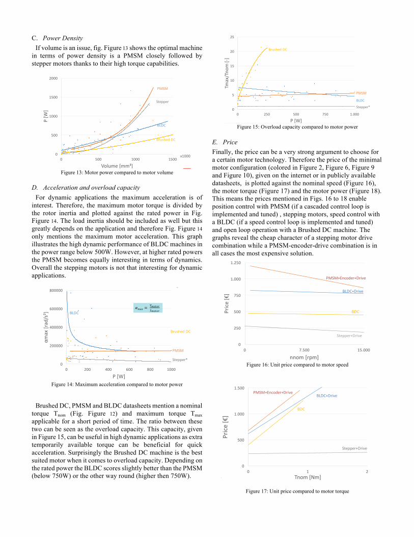
A. Speed When the nominal rotational speed of the electrical motors is
compared to the rated power in Fig. Figure 11 the theoretical statement that a BLDC machine is ideally suited for high speed applications is confirmed. Especially smaller BLDC machines with low inertia are able to obtain high rotational speeds. Stepping motors on the other hand seem to be a rather bad option for high speed applications. The maximum speed of Permanent Magnet Machines is limited by the ability of the power convertor to generate a sinusoidal current profile. Finally, the Brushed DC machine maximum speed will be limited by the wear of the brushes at higher speeds.
Figure 11: Nominal motor speed compared to rated power
B. Torque Depicting the torque compared to the volume as in Fig. Figure
12 reveals the supreme torque density of stepping motors. Thanks to the optimal commutation PMSM machines are characterized by a higher torque density compared to BLDC and Brushed DC machines. The latter shows the lowest maximum torque compared to volume.
Figure 12: Nominal motor torque compared to motor volume
Drive
Dir
Enable
NXT
µController
NXT
t
NS
A A
B
B
ia ia
N S
A1
A2
B1
B2
A1
A2
B1
B2
Drive
Dir
Enable
NXT
µController
NXT
t
ib
ib
B
B
N
S
A A
S
N
15
researchgroupelectromechanicaldrivelinesresearch group electromechanical drivelines
0
5000
10000
15000
20000
0 100 200 300 400 500
nnom
[rpm]
P[W]15
Datasheet Survey
x1000
Stepper
PMSMBLDC
Brushed DC
12
researchgroupelectromechanicaldrivelinesresearch group electromechanical drivelines
12
Datasheet Survey
0
5
10
15
0 500 1000 1500
Tnom
[Nm]
Volume[mm³]
Stepper
PMSM
BLDCBrushed DCx1000
C. Power Density If volume is an issue, fig. Figure 13 shows the optimal machine
in terms of power density is a PMSM closely followed by stepper motors thanks to their high torque capabilities.
Figure 13: Motor power compared to motor volume
D. Acceleration and overload capacity For dynamic applications the maximum acceleration is of
interest. Therefore, the maximum motor torque is divided by the rotor inertia and plotted against the rated power in Fig. Figure 14. The load inertia should be included as well but this greatly depends on the application and therefore Fig. Figure 14 only mentions the maximum motor acceleration. This graph illustrates the high dynamic performance of BLDC machines in the power range below 500W. However, at higher rated powers the PMSM becomes equally interesting in terms of dynamics. Overall the stepping motors is not that interesting for dynamic applications.
Figure 14: Maximum acceleration compared to motor power
Brushed DC, PMSM and BLDC datasheets mention a nominal
torque Tnom (Fig. Figure 12) and maximum torque Tmax applicable for a short period of time. The ratio between these two can be seen as the overload capacity. This capacity, given in Figure 15, can be useful in high dynamic applications as extra temporarily available torque can be beneficial for quick acceleration. Surprisingly the Brushed DC machine is the best suited motor when it comes to overload capacity. Depending on the rated power the BLDC scores slightly better than the PMSM (below 750W) or the other way round (higher then 750W).
Figure 15: Overload capacity compared to motor power
E. Price Finally, the price can be a very strong argument to choose for a certain motor technology. Therefore the price of the minimal motor configuration (colored in Figure 2, Figure 6, Figure 9 and Figure 10), given on the internet or in publicly available datasheets, is plotted against the nominal speed (Figure 16), the motor torque (Figure 17) and the motor power (Figure 18). This means the prices mentioned in Figs. 16 to 18 enable position control with PMSM (if a cascaded control loop is implemented and tuned) , stepping motors, speed control with a BLDC (if a speed control loop is implemented and tuned) and open loop operation with a Brushed DC machine. The graphs reveal the cheap character of a stepping motor drive combination while a PMSM-encoder-drive combination is in all cases the most expensive solution.
Figure 16: Unit price compared to motor speed
Figure 17: Unit price compared to motor torque
14
researchgroupelectromechanicaldrivelinesresearch group electromechanical drivelines
0
500
1000
1500
2000
0 500 1000 1500
P[W
]
Volume[mm³]14
Datasheet Survey
x1000
Stepper
PMSM
BLDC
Brushed DC
16
researchgroupelectromechanicaldrivelinesresearch group electromechanical drivelines
16
Datasheet Survey
0
200000
400000
600000
800000
0 200 400 600 800 1000
αmax[rad/s²]
P[W]
Stepper*
PMSM
BLDC
Brushed DC
!"#$ = '()*)+,()*)+
13
researchgroupelectromechanicaldrivelinesresearch group electromechanical drivelines
Datasheet Survey
0
5
10
15
20
25
0 250 500 750 1.000
Tmax/Tno
m[-]
P[W]
Stepper*
PMSM
BLDC
Brushed DC
19
researchgroupelectromechanicaldrivelinesresearch group electromechanical drivelines
19
Datasheet Survey
0
250
500
750
1.000
1.250
0 7.500 15.000
Price
[€]
nnom[rpm]
PMSM+Encoder+Drive
BDC
BLDC+Drive
Stepper+Drive
18
researchgroupelectromechanicaldrivelinesresearch group electromechanical drivelines
18
Datasheet Survey
0
500
1.000
1.500
0 1 2
Price
[€]
Tnom[Nm]
PMSM+Encoder+Drive
BDC
BLDC+Drive
Stepper+Drive
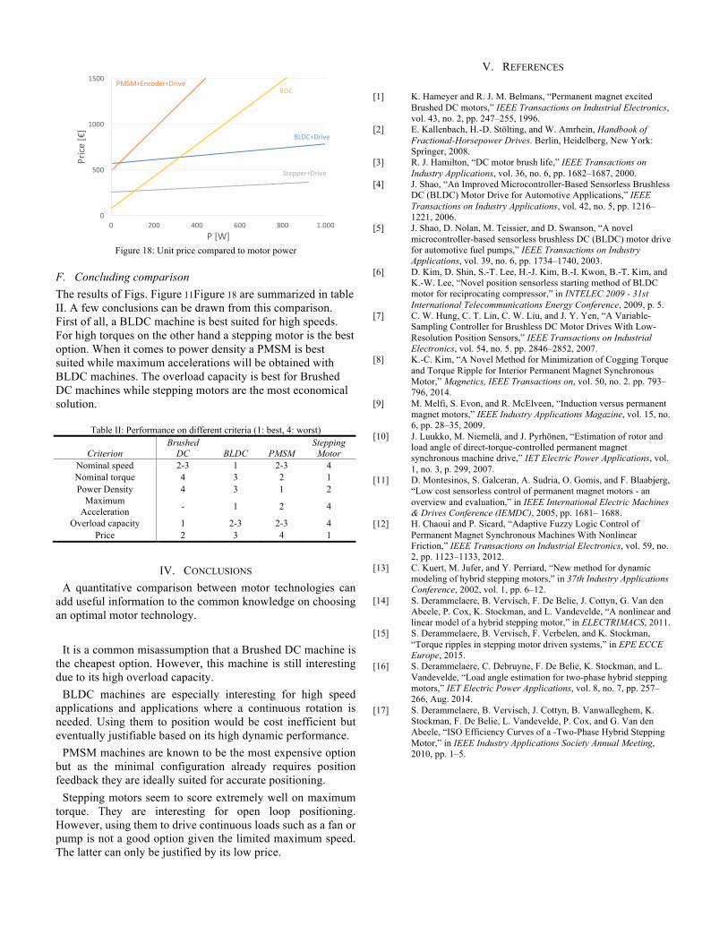
Figure 18: Unit price compared to motor power
F. Concluding comparison The results of Figs. Figure 11Figure 18 are summarized in table II. A few conclusions can be drawn from this comparison. First of all, a BLDC machine is best suited for high speeds. For high torques on the other hand a stepping motor is the best option. When it comes to power density a PMSM is best suited while maximum accelerations will be obtained with BLDC machines. The overload capacity is best for Brushed DC machines while stepping motors are the most economical solution.
Table II: Performance on different criteria (1: best, 4: worst)
Criterion Brushed
DC BLDC PMSM Stepping
Motor Nominal speed 2-3 1 2-3 4 Nominal torque 4 3 2 1 Power Density 4 3 1 2
Maximum Acceleration - 1 2 4
Overload capacity 1 2-3 2-3 4 Price 2 3 4 1
IV. CONCLUSIONS A quantitative comparison between motor technologies can
add useful information to the common knowledge on choosing an optimal motor technology.
It is a common misassumption that a Brushed DC machine is
the cheapest option. However, this machine is still interesting due to its high overload capacity.
BLDC machines are especially interesting for high speed applications and applications where a continuous rotation is needed. Using them to position would be cost inefficient but eventually justifiable based on its high dynamic performance.
PMSM machines are known to be the most expensive option but as the minimal configuration already requires position feedback they are ideally suited for accurate positioning.
Stepping motors seem to score extremely well on maximum torque. They are interesting for open loop positioning. However, using them to drive continuous loads such as a fan or pump is not a good option given the limited maximum speed. The latter can only be justified by its low price.
V. REFERENCES [1] K. Hameyer and R. J. M. Belmans, “Permanent magnet excited
Brushed DC motors,” IEEE Transactions on Industrial Electronics, vol. 43, no. 2, pp. 247–255, 1996.
[2] E. Kallenbach, H.-D. Stölting, and W. Amrhein, Handbook of Fractional-Horsepower Drives. Berlin, Heidelberg, New York: Springer, 2008.
[3] R. J. Hamilton, “DC motor brush life,” IEEE Transactions on Industry Applications, vol. 36, no. 6, pp. 1682–1687, 2000.
[4] J. Shao, “An Improved Microcontroller-Based Sensorless Brushless DC (BLDC) Motor Drive for Automotive Applications,” IEEE Transactions on Industry Applications, vol. 42, no. 5, pp. 1216–1221, 2006.
[5] J. Shao, D. Nolan, M. Teissier, and D. Swanson, “A novel microcontroller-based sensorless brushless DC (BLDC) motor drive for automotive fuel pumps,” IEEE Transactions on Industry Applications, vol. 39, no. 6, pp. 1734–1740, 2003.
[6] D. Kim, D. Shin, S.-T. Lee, H.-J. Kim, B.-I. Kwon, B.-T. Kim, and K.-W. Lee, “Novel position sensorless starting method of BLDC motor for reciprocating compressor,” in INTELEC 2009 - 31st International Telecommunications Energy Conference, 2009, p. 5.
[7] C. W. Hung, C. T. Lin, C. W. Liu, and J. Y. Yen, “A Variable-Sampling Controller for Brushless DC Motor Drives With Low-Resolution Position Sensors,” IEEE Transactions on Industrial Electronics, vol. 54, no. 5. pp. 2846–2852, 2007.
[8] K.-C. Kim, “A Novel Method for Minimization of Cogging Torque and Torque Ripple for Interior Permanent Magnet Synchronous Motor,” Magnetics, IEEE Transactions on, vol. 50, no. 2. pp. 793–796, 2014.
[9] M. Melfi, S. Evon, and R. McElveen, “Induction versus permanent magnet motors,” IEEE Industry Applications Magazine, vol. 15, no. 6, pp. 28–35, 2009.
[10] J. Luukko, M. Niemelä, and J. Pyrhönen, “Estimation of rotor and load angle of direct-torque-controlled permanent magnet synchronous machine drive,” IET Electric Power Applications, vol. 1, no. 3, p. 299, 2007.
[11] D. Montesinos, S. Galceran, A. Sudria, O. Gomis, and F. Blaabjerg, “Low cost sensorless control of permanent magnet motors - an overview and evaluation,” in IEEE International Electric Machines & Drives Conference (IEMDC), 2005, pp. 1681– 1688.
[12] H. Chaoui and P. Sicard, “Adaptive Fuzzy Logic Control of Permanent Magnet Synchronous Machines With Nonlinear Friction,” IEEE Transactions on Industrial Electronics, vol. 59, no. 2, pp. 1123–1133, 2012.
[13] C. Kuert, M. Jufer, and Y. Perriard, “New method for dynamic modeling of hybrid stepping motors,” in 37th Industry Applications Conference, 2002, vol. 1, pp. 6–12.
[14] S. Derammelaere, B. Vervisch, F. De Belie, J. Cottyn, G. Van den Abeele, P. Cox, K. Stockman, and L. Vandevelde, “A nonlinear and linear model of a hybrid stepping motor,” in ELECTRIMACS, 2011.
[15] S. Derammelaere, B. Vervisch, F. Verbelen, and K. Stockman, “Torque ripples in stepping motor driven systems,” in EPE ECCE Europe, 2015.
[16] S. Derammelaere, C. Debruyne, F. De Belie, K. Stockman, and L. Vandevelde, “Load angle estimation for two-phase hybrid stepping motors,” IET Electric Power Applications, vol. 8, no. 7, pp. 257–266, Aug. 2014.
[17] S. Derammelaere, B. Vervisch, J. Cottyn, B. Vanwalleghem, K. Stockman, F. De Belie, L. Vandevelde, P. Cox, and G. Van den Abeele, “ISO Efficiency Curves of a -Two-Phase Hybrid Stepping Motor,” in IEEE Industry Applications Society Annual Meeting, 2010, pp. 1–5.
17
researchgroupelectromechanicaldrivelinesresearch group electromechanical drivelines
17
Datasheet Survey
0
500
1000
1500
0 200 400 600 800 1.000
Price
[€]
P[W]
PMSM+Encoder+DriveBDC
BLDC+Drive
Stepper+Drive