Embed Size (px)
Citation preview

Department of Computer Science
Malin Abrahamsson, Aleksandra Gadji
A Prototype for
SCCP-X
A New Lightweight Protocol for Emulation
of SCCP in Post-SIGTRAN
D Dissertation 30 ECTS
2005:06


A Prototype for
SCCP-X
A New Lightweight Protocol for Emulation
of SCCP in Post-SIGTRAN
Malin Abrahamsson, Aleksandra Gadji
c© 2005 The author and Karlstad University


This thesis is submitted in partial fulfillment of the requirements
for the Masters degree in Computer Science. All material in this
thesis which is not my own work has been identified and no mate-
rial is included for which a degree has previously been conferred.
Malin Abrahamsson
Aleksandra Gadji
Approved, June 7, 2005
Opponent: Therese Sundstrom
Advisor: Johan Garcia
Examiner: Donald Ross
iii


Abstract
Modern telecommunication networks use the Signaling System No. 7 (SS7) for transport
of signaling information. The SS7 system provides for signaling over circuit-switched net-
works. However, packet-switched IP networks are expected to be the technology to replace
circuit-switched networks in the future. When this happens, SS7 should still be able to
provide the same services that it was developed for.
This thesis proposes a prototype for a new lightweight protocol, which utilizes the
advances in the IP technology and makes the convergence to the IP networks profitable.
With a regard to the delimitations made within this project, the accomplished prototype
is believed to constitute a solid base for future work.
v


Acknowledgements
We would like to give thanks to everyone who has helped us during this project. In
particular, we would like to thank Mikael Blom, our supervisor at TietoEnator, for sharing
his knowledge and giving us guidance and support. Without his efforts we would not have
been able to complete this thesis. We would also like to express our gratitude to Johan
Garcia, our supervisor at the Computer Science Department at Karlstad University. His
encouragements and good advice have really been helpful during this project.
A special thanks goes to Nils Bojeryd and Gunnar Lorentzon, for taking their time
to answer all our questions. We give thanks to Jan-Ake Nilsson and Joakim Bengtzon
for their good will and participation. Last, but definitely not least, we owe gratitude to
Karl-Johan Grinnemo for his involvement and technical expertise.
vii

Contents
1 Introduction 1
2 Background 5
2.1 SS7 . . . . . . . . . . . . . . . . . . . . . . . . . . . . . . . . . . . . . . . . 6
2.1.1 Message Transfer Part . . . . . . . . . . . . . . . . . . . . . . . . . 8
2.1.2 Signaling Connection Control Part . . . . . . . . . . . . . . . . . . 9
2.1.3 Transaction Capabilities Application Part . . . . . . . . . . . . . . 12
2.2 SIGTRAN . . . . . . . . . . . . . . . . . . . . . . . . . . . . . . . . . . . . 13
2.2.1 Stream Control Transmission Protocol . . . . . . . . . . . . . . . . 14
2.2.2 User Adaptation layers . . . . . . . . . . . . . . . . . . . . . . . . . 15
2.3 Post-SIGTRAN . . . . . . . . . . . . . . . . . . . . . . . . . . . . . . . . . 16
2.3.1 The SCCP-X Protocol . . . . . . . . . . . . . . . . . . . . . . . . . 18
3 Design 23
3.1 Scope of Design . . . . . . . . . . . . . . . . . . . . . . . . . . . . . . . . . 23
3.2 Prototype Network . . . . . . . . . . . . . . . . . . . . . . . . . . . . . . . 26
3.3 Surrounding Environment . . . . . . . . . . . . . . . . . . . . . . . . . . . 27
3.3.1 Common Parts . . . . . . . . . . . . . . . . . . . . . . . . . . . . . 28
3.3.2 Management Module . . . . . . . . . . . . . . . . . . . . . . . . . . 31
3.3.3 TCAP . . . . . . . . . . . . . . . . . . . . . . . . . . . . . . . . . . 32
ix

3.3.4 SCTP . . . . . . . . . . . . . . . . . . . . . . . . . . . . . . . . . . 35
3.4 Message Header . . . . . . . . . . . . . . . . . . . . . . . . . . . . . . . . . 40
3.5 Peer-to-Peer Messages . . . . . . . . . . . . . . . . . . . . . . . . . . . . . 40
3.6 The State Machine . . . . . . . . . . . . . . . . . . . . . . . . . . . . . . . 42
3.6.1 Module States . . . . . . . . . . . . . . . . . . . . . . . . . . . . . . 42
3.6.2 Association States . . . . . . . . . . . . . . . . . . . . . . . . . . . 45
3.7 Use Cases . . . . . . . . . . . . . . . . . . . . . . . . . . . . . . . . . . . . 47
4 Implementation Basics 53
4.1 Events . . . . . . . . . . . . . . . . . . . . . . . . . . . . . . . . . . . . . . 53
4.2 State-Event Matrix . . . . . . . . . . . . . . . . . . . . . . . . . . . . . . . 54
4.3 Dispatcher . . . . . . . . . . . . . . . . . . . . . . . . . . . . . . . . . . . . 55
5 Stream Selection 57
5.1 Background . . . . . . . . . . . . . . . . . . . . . . . . . . . . . . . . . . . 58
5.1.1 Protocol Classes . . . . . . . . . . . . . . . . . . . . . . . . . . . . . 58
5.1.2 Signaling Link Selection . . . . . . . . . . . . . . . . . . . . . . . . 58
5.1.3 SCTPs Multi-Streaming . . . . . . . . . . . . . . . . . . . . . . . . 60
5.1.4 SCTPs Ordered and Unordered Delivery . . . . . . . . . . . . . . . 60
5.2 Problem Formulation . . . . . . . . . . . . . . . . . . . . . . . . . . . . . . 61
5.3 Design . . . . . . . . . . . . . . . . . . . . . . . . . . . . . . . . . . . . . . 61
5.3.1 Alternative 1 . . . . . . . . . . . . . . . . . . . . . . . . . . . . . . 62
5.3.2 Alternative 2 . . . . . . . . . . . . . . . . . . . . . . . . . . . . . . 63
5.3.3 Design Choice . . . . . . . . . . . . . . . . . . . . . . . . . . . . . . 64
5.4 Implementation . . . . . . . . . . . . . . . . . . . . . . . . . . . . . . . . . 65
6 Address Resolution 67
6.1 Preconfigured Address Resolution . . . . . . . . . . . . . . . . . . . . . . . 68
6.2 Background to the DNS Address Resolution . . . . . . . . . . . . . . . . . 70
x

6.2.1 Domain Name System . . . . . . . . . . . . . . . . . . . . . . . . . 71
6.2.2 Dynamic Delegation Discovery System . . . . . . . . . . . . . . . . 73
6.2.3 ENUM . . . . . . . . . . . . . . . . . . . . . . . . . . . . . . . . . . 77
6.3 Problem Formulation . . . . . . . . . . . . . . . . . . . . . . . . . . . . . . 81
6.4 Design . . . . . . . . . . . . . . . . . . . . . . . . . . . . . . . . . . . . . . 82
6.5 Implementation . . . . . . . . . . . . . . . . . . . . . . . . . . . . . . . . . 86
7 Conclusions 87
8 Future Work 91
9 Experiences and Problems 95
References 97
A Abbreviations 99
xi


List of Figures
2.1 A simplified SS7 signaling network . . . . . . . . . . . . . . . . . . . . . . 7
2.2 SS7 stack . . . . . . . . . . . . . . . . . . . . . . . . . . . . . . . . . . . . 8
2.3 An example of GTT in the SS7 architecture . . . . . . . . . . . . . . . . . 11
2.4 SIGTRAN stack . . . . . . . . . . . . . . . . . . . . . . . . . . . . . . . . . 13
2.5 Post-SIGTRAN stack . . . . . . . . . . . . . . . . . . . . . . . . . . . . . . 17
2.6 Alternative 1: SCCP-X as the application protocol . . . . . . . . . . . . . 18
2.7 Alternative 2: TCAP as the application protocol and SCCP-X as an appli-
cation specific module . . . . . . . . . . . . . . . . . . . . . . . . . . . . . 19
2.8 An interworking function makes it possible for two different signaling archi-
tectures to communicate . . . . . . . . . . . . . . . . . . . . . . . . . . . . 22
3.1 The prototype network . . . . . . . . . . . . . . . . . . . . . . . . . . . . . 26
3.2 Request- and confirmation/indication primitives exchanges . . . . . . . . . 28
3.3 The modules communicate with each other via Common Parts . . . . . . . 29
3.4 Primitives used in the prototype . . . . . . . . . . . . . . . . . . . . . . . . 39
3.5 The SCCP-X header . . . . . . . . . . . . . . . . . . . . . . . . . . . . . . 40
3.6 UDT message . . . . . . . . . . . . . . . . . . . . . . . . . . . . . . . . . . 41
3.7 The module state machine diagram . . . . . . . . . . . . . . . . . . . . . . 43
3.8 The association state machine diagram . . . . . . . . . . . . . . . . . . . . 46
3.9 The sequence diagram of the basic Use Case . . . . . . . . . . . . . . . . . 48
xiii

3.10 The sequence diagram of the Use Case when the client SCTP fails to estab-
lish an association with the server . . . . . . . . . . . . . . . . . . . . . . 50
3.11 The sequence diagram of the Use Case when a subsystem failure occurs . . 52
4.1 The illustration of the legal module events . . . . . . . . . . . . . . . . . . 54
4.2 The illustration of the legal association events . . . . . . . . . . . . . . . . 55
4.3 SCCP-X event handling . . . . . . . . . . . . . . . . . . . . . . . . . . . . 55
5.1 Illustration of the signaling link selection mechanism . . . . . . . . . . . . 59
5.2 SCTP multi-streamed association . . . . . . . . . . . . . . . . . . . . . . . 60
5.3 Illustration of the stream selection mechanism . . . . . . . . . . . . . . . . 64
6.1 The address resolution within Post-SIGTRAN . . . . . . . . . . . . . . . . 67
6.2 GTT using preconfigured address information . . . . . . . . . . . . . . . . 69
6.3 GTT performed by using the DNS address resolution . . . . . . . . . . . . 70
6.4 The DDDS Algorithm . . . . . . . . . . . . . . . . . . . . . . . . . . . . . 74
6.5 Retrieving the rules from a DDDS database . . . . . . . . . . . . . . . . . 75
6.6 The packet format for the NAPTR record. . . . . . . . . . . . . . . . . . . 76
6.7 The ’e164.arpa’ namespace . . . . . . . . . . . . . . . . . . . . . . . . . . . 77
6.8 Retrieving the rules from a DNS database . . . . . . . . . . . . . . . . . . 78
6.9 An example of the DDDS algorithm with ENUM as the DDDS application 80
6.10 An example of a DNS NAPTR RR . . . . . . . . . . . . . . . . . . . . . . 81
6.11 The DNS address resolution . . . . . . . . . . . . . . . . . . . . . . . . . . 83
6.12 An SS7 entry added . . . . . . . . . . . . . . . . . . . . . . . . . . . . . . . 84
6.13 The GT to IP address translation. . . . . . . . . . . . . . . . . . . . . . . . 85
xiv

List of Tables
3.1 Key elements of SCCP-X, which are included in the prototype . . . . . . . 25
xv


Chapter 1
Introduction
Unlike computer networks, a telecommunication network is actually two networks in one; it
consists of two separate logical elements. First there is a network which actually carries the
user voice and data traffic. The second element is the signaling network which carries the
call control traffic. The main task of the signaling network is to transfer the information
which is necessary for setting up, tearing down and maintaining connections between nodes
in the network. Besides the basic management of telephone calls, the signaling network
can also provide enhanced telephone services such as call forwarding, three-way calling,
calling party name/number display etc.
The most common signaling system, which is used in the modern telecommunication
networks, is the Signaling System No. 7 (SS7). For the time being, SS7 provides signaling
over circuit-switched networks, but in the future, IP networks will most likely replace these
circuit-switched networks.
Since large efforts and costs have been invested in development of today’s SS7 net-
works, the transition to IP is expected to take place gradually. The first step was the
introduction of the SIGTRAN architecture that has been developed by the IETF. Within
SIGTRAN, SS7 messages are transmitted over IP but without taking the full advantage
of IPs capabilities. In addition, SIGTRAN is conceived to be unnecessary complex.
1

2 CHAPTER 1. INTRODUCTION
The purpose of this thesis is to evolve signaling transport beyond SIGTRAN and the
Post-SIGTRAN architecture has been proposed. This architecture is believed to constitute
the next step towards the IP-based SS7 networks. The key component proposed by this
work is a prototype for a new lightweight protocol called SCCP-X, designed to make it
possible for operators to achieve a more economical network infrastructure. In addition,
IP capabilities, such as quality of service and DNS, are meant to be utilized. The SCCP-
X protocol is meant to transparently replace the corresponding SCCP protocol in the
traditional SS7 stack. The SS7 applications are meant to remain intact and unaware of
the fact that their messages are sent over IP. The protocol that has been chosen as the
transport protocol within Post-SIGTRAN is SCTP. SCTP is a relatively new protocol that
has been developed within SIGTRAN. SCTP has the ability to provide multi-streaming
and is suitable for the transport of the time-sensitive data.
This thesis is organized in the following way. Chapter 2 gives a brief background to the
project. Section 2.1 describes the legacy SS7 architecture and supplies a short introduction
of SCCP, the protocol that SCCP-X is meant to replace. Section 2.2 describes the legacy
SIGTRAN architecture along with the SCTP protocol which is also used within Post-
SIGTRAN. The concept of Post-SIGTRAN and the key elements of the new SCCP-X
protocol are presented in Section 2.3.
Chapter 3 contains some important aspects of the design of the prototype. The time
frame of the project did not allow all the SCCP-X features to be considered. The necessary
delimitations are stated in Section 3.1. The simple network scenario that the prototype
has been tested for is presented in Section 3.2, and the communication between SCCP-X
and its surrounding environment is described in Section 3.3. Section 3.4 supplies a short
description of the SCCP-X header and is followed by a brief presentation of the peer-to-peer
messages used within the prototype.
As most protocols, SCCP-X can be described as a large state machine. The states
defined for the prototype are presented in Section 3.6. The last section of Chapter 3

3
illustrates the use cases that are considered within the prototype.
The basics of the prototype implementation are given in Chapter 4. The same chapter
describes the key concepts of the SCCP-X module, that is, the events, the state-event
matrix and the dispatcher of the prototype.
As mentioned above, SCCP-X is meant to run over SCTP. Due to SCTPs multi-
streaming capability, SCCP-X must provide a stream selection mechanism, which is pre-
sented in Chapter 5. Section 5.1 contains the background needed to understand the mech-
anism. How the mechanism is designed and implemented is described in Section 5.3 and
Section 5.4, respectively.
Since one of the goals of this thesis is to examine the feasibility for SS7 applications
to run on top of IP networks, the addresses that are used within SS7 must be translated
so that IP can utilize them. The concept of the address resolution is further described in
Chapter 6. Initially, a simpler solution with a preconfigured address mapping is applied.
That solution is presented in Section 6.1. The definite solution for the address resolution
would be to utilize the existing Domain Name System (DNS) services. The implementation
of that solution was not possible to realize within the time frame of the project. Still, the
background for the solution, as well as the problem formulation and discussed design
aspects are further presented in Sections 6.2 to 6.4.
The conclusions and tasks that remain for future work are presented in Chapters 7
and 8, respectively.
Finally, Chapter 9 provides a discussion of the various problems that arose during the
project.
Since this thesis contains a large number of abbreviations, a list of all abbreviations
that are used can be found in Appendix A.


Chapter 2
Background
Ever since 1876, when Alexander Graham Bell made the first voice transmission over wire,
the Public Switched Telephone Network (PSTN) has been evolving. From the beginning,
there was no dialing of numbers. Instead, all devices needed to be directly connected with
a physical wire. To communicate, one person picked up the phone and another person
was simply on the other end. In other words, each user needed a physical cable to every
location the user wanted to call. It is not difficult to understand that such a setup is
neither cost-effective nor feasible.
Due to the impossibility of setting up cables between everyone on Earth, a device called
switch was developed. Instead of connecting to each other, users now needed only a single
cable to the nearest switch. At first, these switches were actually telephone operators that
asked the callers where they wanted to dial and then manually connected the two voice
paths. Over the years, electronic switches replaced the telephone operators.
In tact with rapid social changes, growing industries and increasing needs for broad
communications, demand for phones increased steadily. To answer this demand, telephone
companies continued to add more and more wires. At some point, they realized that they
must find a way to use telephone wires more efficiently. The concept was obvious - the most
efficient way to use wires for conversation was to stop using them for anything other than
5

6 CHAPTER 2. BACKGROUND
the conversation. At the time, the wire that was used for the conversation was also used
to carry all the information that was necessary to connect and manage that conversation.
Such information is referred to as signaling information. The solution was to put the
signaling information in a separate network that would exist within the PSTN network
and control it.
The signaling information is necessary to establish and tear down a connection and route
the actual content of the telephone call from the origin to the destination. A telephone call
may consist of an ordinary voice transmission, a data transmission when the call parties
are using modems, or a fax transmission when the two parties are using fax machines.
Independent of the type, it would be impossible to transfer the content of the telephone
call without signaling transport.
In this chapter, three signaling architectures are described. These architectures consti-
tute the background information needed for the project. Signaling System No. 7 (SS7) is
the most common standard for signaling networks. The SS7 architecture provides signaling
transport over circuit-switched networks and it is described in Section 2.1. As mentioned
in the introduction, IP networks will most likely replace the circuit-switched networks in
the future. The first step to convert signaling transport to the IP domain was enabled by
the introduction of the SIGTRAN architecture, which is described in Section 2.2. Due to
the drawbacks of SIGTRAN, the Post-SIGTRAN architecture has been proposed. This
architecture is believed to constitute the next step towards IP-based networks and it is
described in Section 2.3.
2.1 SS7
As mentioned above, SS7 [19] is a global standard for signaling networks. In other words,
SS7 defines the procedures and protocols by which network elements in the PSTN network
exchange signaling information. This information is conveyed in the form of messages.
2.1. SS7 7
In the SS7 network, messages are exchanged via signaling channels, also known as links.
Every node that exchanges SS7 information is an SS7 system in the network. These nodes
are called Signaling Points (SP), each identified by a unique Signaling Point Code (SPC)
address. Further, the SS7 messages that are exchanged in the network are assigned both
an origin and a destination address, Originating Point Code (OPC) and Destination Point
Code (DPC) respectively. These identities allow the Message Transfer Part (MTP) to
interpret and route the messages through the network to the suitable destination. MTP
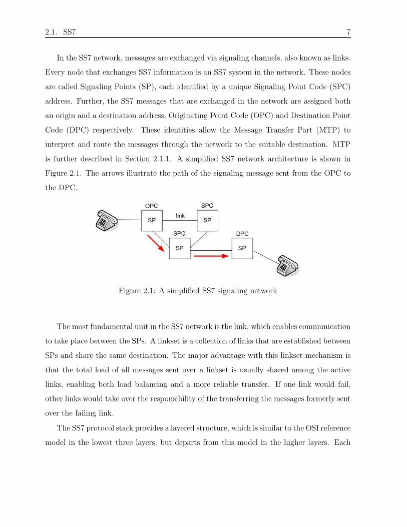
is further described in Section 2.1.1. A simplified SS7 network architecture is shown in
Figure 2.1. The arrows illustrate the path of the signaling message sent from the OPC to
the DPC.
Figure 2.1: A simplified SS7 signaling network
The most fundamental unit in the SS7 network is the link, which enables communication
to take place between the SPs. A linkset is a collection of links that are established between
SPs and share the same destination. The major advantage with this linkset mechanism is
that the total load of all messages sent over a linkset is usually shared among the active
links, enabling both load balancing and a more reliable transfer. If one link would fail,
other links would take over the responsibility of the transferring the messages formerly sent
over the failing link.
The SS7 protocol stack provides a layered structure, which is similar to the OSI reference
model in the lowest three layers, but departs from this model in the higher layers. Each

8 CHAPTER 2. BACKGROUND
layer performs its function in sequence and then hands the message off to the next layer.
As it shows in Figure 2.2, the lowest three layers form the MTP. The higher layers (SCCP,
ISUP, TUP etc.), above MTP, provide different services and are implemented depending
on the requirements of the network. SCCP is important for understanding the concept of
the SCCP-X prototype, and it is therefore briefly described in Section 2.1.2. TCAP is one
possible application layer that can run over SCCP in the SS7 stack. It is the application
layer chosen within the prototype and it is therefore described in Section 2.1.3. One possible
network architecture, within which the SS7 protocol suite applies, is shown in Figure 2.2.
Figure 2.2: SS7 stack
2.1.1 Message Transfer Part
MTP represents the common transport layer in SS7 networks [19], it is responsible for
routing of messages in a secure and reliable way using OPC and DPC.
MTP Layer 1 represents the physical layer and is responsible for the connection of SPs
to the transmission network and also maintaining the physical links.
MTP Layer 2 provides reliable transfer of signaling information between different SPs
in the network. Primarily, this involves error checking and possibly error correction, flow
control and assembly of outgoing messages into packets.

2.1. SS7 9
MTP Layer 3 is responsible for message routing and network management. The latter
involves the routing control and error handling, while message routing relates to forward-
ing of messages to the correct destination. One important feature in MTP3 is message
distribution, which ensures that the correct upper layer (SCCP, ISUP, TUP etc.) receives
a particular message. The distribution is accomplished by the service indicator contained
in a message. Each of the possible protocols that run over MTP has been allocated a
particular value. MTP3 inspects the value and then insures that the data part of the
message is passed to the correct receiving layer. Another important task of MTP3 is to
balance the distribution of messages that are transmitted over a linkset between two SPs.
For most upper layers1, this feature is accomplished by the Signaling Link Selection (SLS)
mechanism.
2.1.2 Signaling Connection Control Part
SCCP [6, 5, 7, 8, 9] is a component of the SS7 protocol suite that provides additional
functionality to those of the MTP layer. These functionalities are needed to be able to
transport signaling messages in signaling networks. SCCP provides two principal modes of
data transfer: connection-oriented (CO) and connection-less (CL). The latter one allows
data to be transferred without prior negotiation as opposed to CO where a session must
be initiated before data transfer can begin.
SCCP is further subdivided into four protocol classes [8] described as follows:
• class 0 : Basic connectionless class
• class 1 : Sequenced connectionless class
• class 2 : Basic connection-oriented class
• class 3 : Flow control connection-oriented class
1TUP does not support SLS.

10 CHAPTER 2. BACKGROUND
MTP requires only a SPC to route a message from origin to its destination, but this
information is not always sufficient. An SP can contain several applications, called subsys-
tems, to which different kinds of messages can be directed. SCCP can differentiate between
these applications with so-called Sub-System Numbers (SSNs), as shown in Figure 2.3 [19].
Further, SCCP provides an important task when routing data, namely Global Title
Translation (GTT). A Global Title (GT) is an SS7 application address, such as a free
phone number2, a SIM card number or a mobile subscriber identification number, used in
SCCP for routing signaling messages. Typically, a GT is a globally unique address, which
can refer to only one destination system. Aside from its attributes, a GT can roughly be
compared to a telephone number. There are several types of GT, which in turn consist of
different number formats as described below.
• The E.164 format is the standard international telephone number, used to identify a
subscriber or a network node.
• The E.212 format, or International Mobile Subscriber Identity (IMSI), is the number
that uniquely, identifies mobile terminals and mobile users in mobile networks. It
consists of a Mobile Country Code (MCC), a Mobile Network Code (MNC) and a
Mobile Station Identification Number (MSIN).
• The E.214 format has the same purpose as E.212. It is a hybrid composed of two
parts: the E.164 part and the E.212 part.
In general, E.212 and E.214 addresses are used to route a call to the correct network
during call setup. When the correct network is found, E.164 addresses are used for the
direct communication between two nodes.
When sending a message to the MTP layer, the GT can not be used to identify the
destination, since MTP handles SPCs. Therefore, a translation mechanism is needed. The
2Free phone numbers are numbers that can be dialed by anyone and the recipient pays for the call

2.1. SS7 11
GTT is the procedure by which SCCP translates a GT into the SPC and SSN of the
destination SP, which enables the MTP layer to pass the message forward to the correct
destination [19]. This mechanism is illustrated in Figure 2.3.
Figure 2.3: An example of GTT in the SS7 architecture
The GTT functionality is even more complicated than Figure 2.3 illustrates. It is not
always possible to get to the destination SPC + SSN as a result from the first GTT,
performed at the origin. Instead, the GTT may result in a SPC and a GT value of another
SP, which lies on the path to the destination. SCCP then routes the message to this SP,
enabling a ’hop-by-hop’ communication between nodes. When the message reaches the
SP, it is passed up to the SCCP layer, which performs a new GTT and then routes the
message forward. This process is repeated until the message reaches its destination.
When SCCP receives a message, it can easily distinguish if GTT is needed or if the
destination is reached and the message should be distributed to local higher layer. If
the routing indicator, contained in the SCCP message, indicates that routing should be
performed using SSN, no translation is needed and the message has reached its destination.
On the other hand, if it indicates that routing should be performed using GT, a translation
is needed and the message has not yet reached its destination.

12 CHAPTER 2. BACKGROUND
2.1.3 Transaction Capabilities Application Part
TCAP [19] is one possible representation of the application layer in the SS7 protocol suite.
The purpose of TCAP is to enable the use of Intelligent Network (IN) services. The IN is
a telephone network architecture that separates service logic from switching equipment. In
other words, the intelligence is moved from the switch and hosted in network nodes. The
main advantage with this approach is that switches do not have to be redesigned when
new services are added.
The services are stored in telephone company databases, which are interfaced by a so-
called Service Control Point (SCP). Since a switch does not store any information in the
IN architecture, it must query a SCP to obtain the required information. The switch that
queries a SCP is called a Service Switching Point (SSP). When a switch wishes to retrieve
information from a SCP, TCAP messages are used to query the SCP. In other words,
TCAP is first and foremost used for querying and retrieval of database-information. For
that purpose it uses the SCCP connectionless service.
The databases store all kinds of service information, for example subscribers’ services,
IN services, SIM card validation services and routing of special service numbers [20]. If
the desirable information is routing information for special service numbers, then a TCAP
message is used to query a SCP to determine the routing number associated with a dialed
number, for instance a free phone number. If the desirable information is SIM card val-
idation, TCAP messages can query the SCP to determine the service profile of the SIM
card. More specifically, validation of SIM cards is used when a mobile subscriber roams
into a new Mobile Switching Centre (MSC) area. The Visitor Location Register (VLR)
requests service profile information from the Home Location Register (HLR) using MAP
(Mobile Application Parts) information carried within a TCAP message [2]. MAP is an
application that runs on top of the TCAP layer.
Another important component of mobility networks is CAP (CAMEL3 Application
3Customized Applications for Mobile Network Enhanced Logic

2.2. SIGTRAN 13
Parts) that is used to implement CAMEL. CAMEL is an extension of IN concept. In the
same way as MAP, CAP runs over TCAP.
2.2 SIGTRAN
Due to the increasing availability of IP-networks, a possibility to use these networks to
transport signaling data has arisen. Therefore, methods to connect the SS7 domain to the
IP domain have been created and the SIGTRAN4-architecture and protocol suite has been
defined by the IETF [3].
The SIGTRAN protocol suite describes a way in which real-time SS7 signaling data
can be transported over IP networks. This protocol suite is made up of a new transport
layer, Stream Control Transmission Protocol (SCTP) and a set of User Adaptation (UA)
layers, which mimic the services of the lower layers of SS7. The SCTP and the UA layers
are described in Section 2.2.1 and Section 2.2.2, respectively. One possible network archi-
tecture, within which the SIGTRAN protocol suite applies, is shown in Figure 2.4. The
new layers that are introduced within SIGTRAN are shown in bold style.
Figure 2.4: SIGTRAN stack
4SIGTRAN stands for SIGnaling TRANsport

14 CHAPTER 2. BACKGROUND
2.2.1 Stream Control Transmission Protocol
Stream Control Transmission Protocol (SCTP) is a new transport protocol, designed with
the transport of time-sensitive (PSTN) signaling over IP networks in mind [24, 10]. SCTP
aims to address the shortcomings of Transmission Control Protocol (TCP), while still
remaining flexible enough to be of general use.
TCP is the most common transport protocol in IP networks, but it has a number of
limitations in signaling transmission scenarios and is therefore not suitable to carry such
kind of data. One of the most significant limitations is the fact that TCP provides a single
stream of data and guarantees strict order of delivery. This makes it ideal for delivery
of large pieces of data, like files or e-mail messages. On the other hand, this quality is
not a desirable feature when considering transmission of signaling data. Since TCP only
supply a single stream of data, it is very sensitive to delays caused by the network. When a
packet arrives out of order at its destination, TCP will hold up delivery of all the data until
the correct sequence can be restored, typically by a retransmission. This phenomenon is
known as Head Of Line (HOL) blocking and causes unnecessary delays to the upper layer
applications. Using TCP for SS7 messages implies that a single TCP connection would
carry many signaling connections. If one of these suffers data loss, it would result in a delay
for all other signaling connections (calls). Another limitation is that TCP is byte-stream
oriented, which implies that applications must add their own marking to delineate their
messages. This would create unnecessary complexity considering that PSTN signaling
consists of messages.
SCTP was developed to address the problems described above. One of the novel services
provided by SCTP, which solves TCPs HOL blocking problem, is multi-streaming. Multi-
streaming is designed to allow users to divide one SCTP connection, called association,
into several logical streams of data. A particular application or resource is then assigned
to each stream. The purpose of this approach is that errors or delays on one stream will
not interfere with delivery on another stream. In other words, multi-streaming allows for

2.2. SIGTRAN 15
independent delivery among data streams.
Another improving feature of SCTP is its ability to provide the service of multihoming,
which allows the end points to have multiple IP addresses. This service is particularly
important for systems that need to provide uninterrupted service during resource failures.
Such systems often make use of network redundancy by multihoming their hosts. This
means that if a transmission link between two end points fails, a multihomed host that
is accessible through multiple IP addresses would still be able to receive data through an
alternative source interface. While TCP connection uses a single IP address at each point,
SCTP allows a single association to span all of the IP addresses at each end point. In that
way, SCTP benefits from network-layer redundancy as described above.
Additionally, SCTP is message-oriented and has defined structured frames which en-
close the data. This ensures that the user is relieved from the responsibility to interpret
and split the stream of data into message segments; the transport protocol performs this
task.
Like TCP, SCTP maintains reliability through acks, retransmissions, and an end-to-
end checksum. It also uses a four-way handshake in which a cookie mechanism establishes
an association. This mechanism prevents blind SYN attacks. Although these aspects are
important, they are not relevant within the focus of this report. Therefore, they will not
be described further.
2.2.2 User Adaptation layers
The User Adaptation (UA) layers are named with the service they replace in mind [3].
For example, M3UA and M2UA utilize SCTP to provide the services of MTP3 and MTP2
respectively and SUA provides the services of SCCP. The SIGTRAN adaptation layers
serve a number of universal purposes. The UA layer should, in the UA users point of
view, appear to provide the same services as the SS7 layer it replaces, but it does not
really replace all operations of MTP. In this way, the UA layer is transparent to the

16 CHAPTER 2. BACKGROUND
user, who is unaware that the UA has replaced the original protocol. This characteristic
makes the SIGTRAN technology optimized to co-exist with legacy SS7 networks. However,
SIGTRAN is unnecessary complex and the next step in improving this technology would
be to streamline and minimize the UA layers by making it possible to utilize the additional
capabilities of the IP technology.
2.3 Post-SIGTRAN
It is clear that existing and evolving SS7 applications will remain, and that signaling trans-
port will be needed in the future. Therefore, it is of interest to find a way to support these
applications with a transport service, but not using the SS7/SIGTRAN approach. Al-
though SIGTRAN have the capacity to transport SS7 messages over IP, it is unnecessary
complex and it does not take full advantage of the IP technology. Therefore, efforts have
been made to evolve signaling transport beyond SIGTRAN and the Post-SIGTRAN archi-
tecture has been proposed. Within Post-SIGTRAN it should be possible to make use of
the additional IP capabilities, such as Quality of Service (QoS) management, security, DNS
usage, load balancing and node redundancy, while still making it simpler than SIGTRAN.
A streamlined signaling transport that functions in alignment with the IP technology
has several advantages and some of them are presented below.
The most important advantage with Post-SIGTRAN is that only one network will be
needed for telecommunications. Currently two networks are needed, the signaling network
and the network that transports the actual data. Within the Post-SIGTRAN architec-
ture, the IP network will replace both these networks. Still, the high quality signaling
applications that are employed today, will still work on top of the IP technology.
When removing the need for a signaling network it is assumed that operator savings can
be achieved. This is based on the assumption that it is less expensive to manage only one
network. Consequently, the operator employees would only need to possess knowledge of

2.3. POST-SIGTRAN 17
how to maintain and develop this one network. Further, the absence of a separate signaling
network would probably result in major equipment cut backs. Finally, the need to maintain
and expand the already complex SS7 networks would be completely superfluous.
In today’s network, which is characterized by the co-existence of Time Division Mul-
tiplexing (TDM) and Asynchronous Transfer Mode (ATM) transport, SIGTRAN is ap-
plicable for signaling transport on IP. When operators start converting their networks
to all-IP transport, the Post-SIGTRAN will be more efficient than SIGTRAN. Since the
Post-SIGTRAN approach is less complex and uses the already existing IP technology, it is
believed be a lot simpler to develop. This can be assumed to result in faster releases and
lower research and development costs.
The key of the proposed solution lies in a new lightweight protocol, called SCCP-
X, which is meant to make use of the additional IP capabilities. SCCP-X is an SCCP
replacement protocol which implies that it should provide the same services as the original
SCCP protocol. As the Figure 2.5 shows, SCCP-X will run over SCTP and thereby gain
all the benefits described in Section 2.2.1. The new layer that is introduced within Post-
SIGTRAN is shown in bold style.
Figure 2.5: Post-SIGTRAN stack

18 CHAPTER 2. BACKGROUND
2.3.1 The SCCP-X Protocol
It is not an easy task to make the SS7 applications and services work in the IP world. It
is important to decide where to make the cut between the two architectures. The goal is
to enable the SS7 applications to keep utilizing the SCCP services even though the lower
layers are replaced by SCCP-X on top of SCTP/IP. Two alternatives have been discussed
concerning the design of the SCCP-X solution. In both alternatives, the SCCP-X is a layer
that adapts the application to the underlying transport protocol.
In the first alternative, see Figure 2.6, SCCP-X is the application protocol, which is
identified by a single contact port. Compared to the SS7 environment, SCCP-X will replace
the SCCP protocol and SSN numbers will distinguish all its applications. A disadvantage
with this alternative is that applications need to be aware of the availability and unavail-
ability of the remote SSN, which adds protocol functions to SCCP-X. On the other hand,
the suggestion to develop a protocol with a contact port is used by M3UA and SUA, which
is a positive aspect, considering the fact that it is a well-tried approach.
Figure 2.6: Alternative 1: SCCP-X as the application protocol
In the second alternative, see Figure 2.7, the SCCP-X layer does not include a protocol.
Instead the applications are divided into modules, which provide different services. Each
module contains the specific operations of the service. For instance, if TCAP is needed, it is
included together with an SCCP-X module, which makes it possible to transmit messages

2.3. POST-SIGTRAN 19
using the transport protocol directly. In other words, each application will use a specific
SCCP-X module and each of them should resemble the services offered by SCCP. In this
scenario, TCAP is the application protocol, and the protocol contact port is tied to its
SSN. In this alternative, subsystem can not fail as long as the association is active, so there
is no need for subsystem management messages. On the other hand, a disadvantage with
this proposal is that multiple associations need to be established between node pairs.
Figure 2.7: Alternative 2: TCAP as the application protocol and SCCP-X as an applicationspecific module
Since the first alternative has been tested earlier by M3UA and SUA, this is believed
to be the superior alternative. This implies that SCCP-X is a new lightweight protocol
identified by a single contact port. Multiple applications will run over the same SCCP-X
protocol.
Key Elements of SCCP-X
In this section the key elements of SCCP-X are presented.
In order to streamline and minimize the SCCP-X layer, it has been made dependent on
SCTP as the transport protocol. The goal is to take full advantage of the services offered
by SCTP, removing any functional redundancy and slimming the protocol stack and the
protocol overhead. The alternative to make SCCP-X independent of the transport protocol
20 CHAPTER 2. BACKGROUND
would have caused a more complex SCCP-X, so that alternative is not considered.
Another aspect that contributes to the lightweightness of the SCCP-X protocol is the
addressing principle that has been chosen for Post-SIGTRAN. The approach taken in
SIGTRAN, to support SPCs, is assumed to be the main contributor to its complexity.
Therefore, the support of SPCs is excluded and only GTs are used for addressing within
Post-SIGTRAN. The avoidance of double addressing types will result in reduced architec-
ture complexity. In addition, the absence of SPCs will increase flexibility for cooperating
networks and operators. This is based on the complexity to manage SPCs among networks.
Within a network, a specific collection of SPCs is valid. These SPCs are not unique and
may reappear in other networks. It is up to the operator to maintain the valid SPCs within
its own network. In order to communicate between networks, the different SPC collections
needs to be mapped among one another at the border between networks. The choice to
exclude SPCs in Post-SIGTRAN will remove the need for this mapping since the operators
no longer need to maintain their own address collections. GTs are unique and are adapted
for international use, so these addresses will be recognized in every network.
Although the main objective of SCCP-X is to be a lean protocol with reduced complex-
ity, it is also a SCCP replacement protocol and should therefore provide all the services of
the original SCCP. This means that both connectionless and connection-oriented services
must be supported by SCCP-X. These services imply that the new lightweight protocol
should be able to support ordered delivery. SCCP realizes such delivery by selecting a suit-
able link for the data transmission. In a similar way, SCCP-X should perform a selection
mechanism for SCTP streams. In that way SCCP-X will take advantage of SCTPs ordered
delivery services.
In addition, the original SCCP protocol provides message segmentation/reassembly if
needed. Consequently, SCCP-X should provide the same service. The segmentation service
is provided transparently to the SCCP user. It allows transfer of a block of user data larger
than what can be contained in an SCCP message.

2.3. POST-SIGTRAN 21
Finally, the overlying protocols are expected to send management related messages to
the original SCCP. Since the replacement of SCCP should be transparent to the overly-
ing protocols, SCCP-X must support such messages. Thus, the management procedures
corresponding to the SCCP management should be supported.
As described in Section 2.1.2, the origin and the destination in SS7 networks do not
have a direct route established between each other. Instead, communication is achieved
through a hop-by-hop behavior. In the Post-SIGTRAN architecture, the origin and the
destination share a direct signaling route. This route is constituted by an end-to-end SCTP
association.
An aspect worth considering is whether associations should be established statically or
dynamically. In networks which consist of a low number of nodes, a static configuration
of the network could be optimal. However, networks usually consist of a large number5
of nodes, where static association establishment may be quite time consuming. Therefore,
dynamic associations are considered to be the most suitable solution. In essence, SCTP
should be used in the traditional IP way, i.e. associations should be established when
needed and disconnected when superfluous.
The fundamental aspect of SCCP-X is to make it possible to use any capability provided
by IP, such as security, QoS, load balancing and node redundancy. The IP quality that is
considered to be of the greatest importance is the use of the DNS services to perform the
address resolution. The address resolution can be compared to the Global Title Translation
(GTT) which is utilized by SCCP within the SS7 architecture. When SCCP receives a
message from the upper layer, the destination is identified by its GT address. To be able
to send the message to the destination, SCCP must translate the GT into an address that
is comprehensible by the underlying circuit-switched (CS) networks. Similarly, SCCP-
X needs to perform the address resolution to translate the GT into an address that is
understandable by the underlying IP networks. In IP networks the IP address is used to
5A large number is considered to be in order of tens of thousands.

22 CHAPTER 2. BACKGROUND
route a message to the destination and thus the result of the address resolution should be
an IP address. To sum up, the address resolution within SCCP-X should translate a GT
into an IP address by using a DNS database.
Finally, it is important to state that even though Post-SIGTRAN may become the sig-
naling technology of the future, it must still be able to interwork with legacy SS7/SIGTRAN
networks. This could be accomplished by adding an interworking function between the
Post-SIGTRAN and legacy signaling environments within a network. The interworking
function would then perform mapping between the different representations of nodes and
protocols.
Figure 2.8: An interworking function makes it possible for two different signaling architec-tures to communicate

Chapter 3
Design
This chapter gathers fundamental aspects that have been considered and discussed when
designing the SCCP-X prototype. First of all, the design delimitations stated for the pro-
totype are presented in Section 3.1. This is followed by a short description of the prototype
network in Section 3.2. The SCCP-X module is surrounded by different modules in the
Post-SIGTRAN architecture. Section 3.3 describes the different modules and the commu-
nication between them. Further, the SCCP-X header and the peer-to-peer communication
are briefly described in Section 3.4 and Section 3.5, respectively. Finally, the state machine
that have been defined along with the considered use cases are illustrated in Section 3.6
and Section 3.7.
3.1 Scope of Design
The focus of this work is to design and implement a prototype for the SCCP-X protocol.
The task of implementing all functionalities in SCCP-X is not possible within the time
frame of the project. For that reason, necessary delimitations are stated.
First of all, only the simplest method of communication, connectionless communication,
is included. Due to this delimitation, only SCCP message classes 0 and 1, which provide
23

24 CHAPTER 3. DESIGN
connectionless service, are considered.
Due to the fact that the signaling gateway, or an interworking function between Post-
SIGTRAN and legacy networks requires a lot of work, it is not suitable to start with.
Instead, the prototype is designed for the IP-IP environment. This delimitation eliminates
the need for the segmentation functionality, since IP already provides this service. Thus,
the segmentation is not considered within the scope of the work.
As mentioned before, it has been stated that SCCP-X should be a protocol layer identi-
fied by a single port number. Within the prototype, the port number has a fixed, configured
value.
The project has been divided into two separate parts - the API adaptation and the sup-
plementary protocol functionalities. The API adaptation part includes the implementation
of the protocol skeleton that is needed to enable the communication with the surrounding
environment. The communication between SCCP-X and its surrounding environment is
described in Section 3.3.
As mentioned in the previous chapter, management procedures corresponding to the
original SCCP management must be implemented for the protocol to function. Only those
procedures that are absolutely necessary are considered within the prototype.
The two protocol funtionalities that are considered within the prototype are the ability
to provide ordered delivery of messages and the capability to perform the necessary address
resolution.
The requirement to provide ordered delivery of messages is achieved by a suitable stream
selection mechanism. This mechanism is presented in Chapter 5.
Finally, SCCP-X must translate a GT to an IP address to be able to transmit data.
As described earlier, there are several types of GTs, but within the prototype only E.164
numbers are used. The reason why E.164 is chosen is due to its widespread use in legacy
SS7/SIGTRAN networks. At the time, the prototype uses a preconfigured address resolu-
tion to translate a GT to an IP address. Still, some research concerning the DNS address

3.1. SCOPE OF DESIGN 25
Table 3.1: Key elements of SCCP-X, which are included in the prototype
Key elements of SCCP-X The Prototype
Interworking with Legacy -Connectionless Services xConnection-Oriented Services -Segmentation / Reassembly -Management Procedures x*Ordered Delivery xDynamic Associations -DNS Address Resolution x**Security -QoS -Load Balancing -Node Redundancy -* Only the basic management is supported** Only the prestudy has been performed
resolution is included in the thesis. The address resolution is further described in Chap-
ter 6. As mentioned in the previous chapter, the usage of the IP technology includes many
other potential benefits besides the DNS address resolution, for instance QoS and load
balancing. Though, these benefits are not included within the scope of the thesis.
Since the prototype network, described in the next section, is very simple, static asso-
ciation establishment is possible. In the future, dynamic association establishment should
be explored, but for the time being the simplest solution is chosen. Still, the possibility to
change to the dynamic establishment is provided.
Table 3.1 summarizes the key elements of SCCP-X, which are described in the previous
chapter. Key elements that are marked with an ’x’ are included in the prototype, while
the rest remain for future work.

26 CHAPTER 3. DESIGN
3.2 Prototype Network
The environment in which the prototype was tested is quite simple. Two SPs exchange
signaling information over an association that is established between them. To reduce the
scope of the work, only one association may be established between two SPs. Further, each
SP is assigned only one IP address and only one port number. This simplifies the address
resolution mechanism, by making a GT map to only one single IP address.
Figure 3.1: The prototype network
Since SCCP-X is a SCCP replacement protocol, it should include SCCPs ability to
distinguish between applications which may run on top of an SP. In the same way as SCCP,
SCCP-X accomplishes this distinction by using SSN numbers to address each application.
Still, one specific design choice is stated within the prototype. In order to be able to forward
a message to the correct destination, the SSN number of the destination application must
be known at the origin. The mandatory availability of SSNs is standardized for applications
MAP and CAP that run over TCAP.

3.3. SURROUNDING ENVIRONMENT 27
3.3 Surrounding Environment
The SCCP-X module is not the only module that constitute the Post-SIGTRAN architec-
ture. Within the scope of the prototype, the modules that surround SCCP-X are SCTP,
TCAP and the management module. Below, the motivation why these modules are chosen
is stated.
As described in earlier chapters, SCCP-X is meant to operate using SCTP as the
underlying transport protocol. The SCTP module and the messages exchanged between
SCCP-X and SCTP are described in Section 3.3.4.
Since the main idea is to let SCCP-X replace the original SCCP, the layers above it must
be able to remain intact. Therefore, all the protocols and applications that are currently
running over SCCP, should be able to transparently run over SCCP-X instead. However,
it is an unrealistic task to consider all SCCP users when implementing the prototype.
Therefore, TCAP has been chosen to act as the overlying protocol to SCCP-X. The major
motivation of this choice is the fact that TCAP only uses the connectionless services that
are considered within the scope of the work. The TCAP module and the communication
between SCCP-X and TCAP is described in Section 3.3.3.
Further, SCCP-X needs to communicate with the management application. The Man-
agement module (MM) will be the gateway between the management application and the
SCCP-X module. The MM module and the messages exchanged between SCCP-X and
MM are described in Section 3.3.2.
Instead of applying socket programming, the technology called Common Parts (CP) is
used for communication between different modules. The key elements of CP are described
in Section 3.3.1.
Communication between different modules is maintained with primitive exchanges.
The upper layer sends the request-primitives to the lower layer, which replies with the
confirmation-primitives. If the lower layer sends information to the upper layer on its own
accord, instead of confirming the requested actions, it uses the indication-primitives. These

28 CHAPTER 3. DESIGN
primitive types are presented in the Figure 3.2 below.
Primitives that are sent between the layers are composed of a varying number of pa-
rameters. Only those parameters that are of importance for the prototype will be brought
up in the following sections.
Figure 3.2: Request- and confirmation/indication primitives exchanges
3.3.1 Common Parts
Common Parts (CP) [1] is used for communication between the different modules within
the prototype. CP is a proprietary middleware which has the purpose to provide timer
handling, memory handling and communication facilities. In addition CP also provides log
and trace possibilities, list handling and interrupt handling. CP is the encapsulation of the
platform specific operating system and it isolates all operating system dependencies into
one software module. CP has several largely independent functional blocks. Each block
supplies a specific service, e.g. Inter Module Communication or Memory Handling.
The communication facilities offered by CP are used in the communication between the
protocol layers as well as in the communication with applications using the SS7 stack. In the
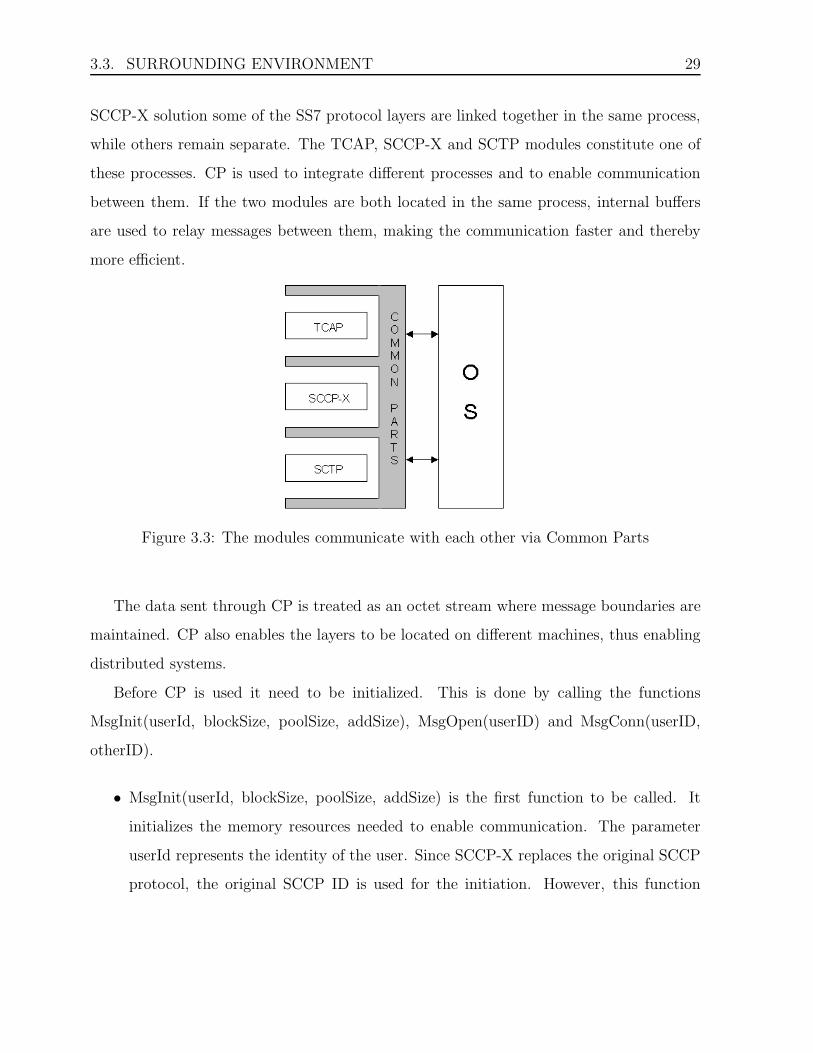
3.3. SURROUNDING ENVIRONMENT 29
SCCP-X solution some of the SS7 protocol layers are linked together in the same process,
while others remain separate. The TCAP, SCCP-X and SCTP modules constitute one of
these processes. CP is used to integrate different processes and to enable communication
between them. If the two modules are both located in the same process, internal buffers
are used to relay messages between them, making the communication faster and thereby
more efficient.
Figure 3.3: The modules communicate with each other via Common Parts
The data sent through CP is treated as an octet stream where message boundaries are
maintained. CP also enables the layers to be located on different machines, thus enabling
distributed systems.
Before CP is used it need to be initialized. This is done by calling the functions
MsgInit(userId, blockSize, poolSize, addSize), MsgOpen(userID) and MsgConn(userID,
otherID).
• MsgInit(userId, blockSize, poolSize, addSize) is the first function to be called. It
initializes the memory resources needed to enable communication. The parameter
userId represents the identity of the user. Since SCCP-X replaces the original SCCP
protocol, the original SCCP ID is used for the initiation. However, this function

30 CHAPTER 3. DESIGN
is not invoked by SCCP-X. Instead, the main SS7 module has the responsibility to
properly initialize the memory for the communication.
• MsgOpen(userId) is then called by each user that wishes to make use of the commu-
nication facilities. The userId parameter represents the user ID of the opener. Also
here the user ID is the original SCCP ID.
• MsgConn(userId, otherId) is called to set up a connection between two users of the
same instance. A user should not send messages to another user before connecting
the other user. The parameters userId and otherId represents the user that called
the MsgConn-function and the user id to connect to, respectively. The users connect
to each other downwards in the stack, i.e. SCCP-X needs to connect to the SCTP
module. To enable the communication with the management application, SCCP-X
also needs to connect to the Management module.
When CP is initialized the communication between the different components can begin.
In this phase an important element is the MSG T message structure, which is described
below, along with the function that actually sends a message.
• The MSG T message structure is mainly used to encapsulate the message. Further
it is used to identify important information about the message, enabling the cor-
rect treatment of the message sent. The attributes mentioned below are used to
discriminate the different messages from one another.
– The primitive of the message, which include the name of the message sent.
– The sender of the message.
– The receiver of the message. Both sender and receiver represent the modules
that communicate with each other via common parts as shown in Figure 3.3.
– The sent message.

3.3. SURROUNDING ENVIRONMENT 31
• MsgSend(MSG T* msg) is used to send a message between two users.
Before calling the function, the user should fill in the fields of the MSG T message
structure. Only the sender and receiver fields are checked by the function. All other
data are passed transparently on to the receiver.
3.3.2 Management Module
The Management module (MM) acts as an interface between the SCCP-X module and the
external management application. When MM receives a message from the management
application, it will distribute the message to the SCCP-X module. When the SCCP-X
module sends a response, this will be received by MM, which will send it to the management
application.
There are a large number of services that MM provides but only a few are considered
as a part of the prototype. Below, the initiation and order related primitives are described.
For more detailed description of MM primitives, see [23].
MM INIT req
At initiation, MM sends an MM INIT req primitive to SCCP-X. This primitive contains
the name of the configuration file and an offset of where the module shall start to read in
the configuration.
MM INIT conf
When SCCP-X has read and verified the configuration it will send the MM INIT conf with
the result parameter set to ’Success’. If the module detects any error during configuration,
the result parameter will be set to an error value.

32 CHAPTER 3. DESIGN
MM ORDER req
Another primitive that is necessary to implement is the MM ORDER req primitive. This
primitive indicates which predefined order the SCCP-X module needs to perform. The
order is specified by an ID parameter. There is a large amount of possible orders but only
two of them are supported by the prototype.
• MM START is the first of the two orders supported by the prototype. This order is
necessary for starting the stack. After the reception of the MM START, the SCCP-X
module must bind itself to the SCTP module. How this is done is described in the
Section 3.3.4.
• MM START ALL ASSOC is the second order needed for the prototype to function
properly. With this order MM orders SCCP-X to start all the associations. This order
is needed due to the limitation of implementing static association establishment and
it should be removed when dynamic association establishment gets implemented.
MM ORDER conf
After performing the ordered action SCCP-X must respond with an MM ORDER conf,
indicating success or failure. This primitive contains an ID parameter that specifies which
type of order that has been performed. The parameter should match the ID parameter
received in the MM ORDER req.
3.3.3 TCAP
As motivated above, TCAP is the actual user of the SCCP-X prototype. Below, the
registration, data transfer and status related primitives are described. The additional
information about primitives that are used for communication between SCCP-X and its
user TCAP is documented in [21].

3.3. SURROUNDING ENVIRONMENT 33
N BIND req
To be able to use the services of SCCP-X, TCAP has to register itself to it, by sending an
N BIND req primitive. The N BIND req primitive contains the SSN number of the user
to bind. SCCP-X needs to check if the received SSN is valid, that is, if it is known as a
local subsystem1.
N BIND conf
After the validation of the SSN, SCCP-X replies with an N BIND conf containing the
result of the registration.
N UNBIND req
When TCAP wants to go out of service it issues an N UNBIND req to SCCP-X.
N UNITDATA req
Since only connectionless services are supported, there is no need to implement any of the
connection-oriented related primitives. There is only one primitive that is needed for data
transfer within connectionless procedures - the N UNITDATA req primitive.
The N UNITDATA req primitive is used by TCAP in order to request transfer of user
data. This primitive contains the parameters ’called address’ and ’calling address’ that
serve to identify the destination and origin respectively. These parameters may contain a
combination of GT, SSN and SPC. Since SPCs are not supported within Post-SIGTRAN,
the received SPC value is ignored. Instead, SCCP-X shall perform mapping between GT
and IP addresses, so the GT value of the address parameters is extracted from the primitive.
The SCCP-X module at the receiving side must know to which subsystem it should
send the received message. Therefore, the SSN value of the ’called address’ parameter is
1Since TCAP does not have an SSN of its own it can not be registered as an SCCP-X subsystem. It isthe SSN of the application that runs over TCAP that will be registered.

34 CHAPTER 3. DESIGN
also extracted. In real SS7 scenarios, the SSN value does not need to be known for every
N UNITDATA req. To avoid complications that the absence of the SSN would involve,
this value is always included in the context of the prototype.
Besides the address parameters that must be decoded and retrieved from the N UNITDATA req
primitive, there is also an important parameter that indicates if data must be send in se-
quence or not. This parameter is called ’sequence control’ and can contain two different
values: 0 = sequence control OFF and 1 = sequence control ON. The information ob-
tained from this parameter have a significant importance considering the implementation
of the stream selection mechanism. Further, there is an additional parameter that is also
important for the stream selection mechanism, i.e. the ’reference parameter’. How these
parameters are used is described in Chapter 5.
N UNITDATA ind
At the destination, SCCP-X uses the N UNITDATA ind primitive to indicate delivery
of user data to the destination user. Parameters associated with the N UNITDATA ind
primitive contain all the information necessary for SCCP-X to deliver the user data to
TCAP.
N STATE ind
The purpose of the N STATE ind primitive is to inform the bound user about the other
users that are active. In the context of the prototype, the N STATE ind is used to let
TCAP know which associations are active and ready to use. More specific, within the
prototype, SCCP-X triggers TCAP to start sending data with an N STATE ind primitive.
This solution is necessary because the prototype does not support all management messages
that are needed to emulate the original SS7 behaviour. Since this is not the actual purpose
of the N STATE ind it should be overlooked within future work.
Within the prototype, N STATE ind is also used to inform the user if an error occurs

3.3. SURROUNDING ENVIRONMENT 35
at the destination. In traditional SS7 networks, the complete message would have been
returned to the upper layer within an N NOTICE ind primitive. However, one delimitation
has been made within the prototype. Namely, the upper layer is only informed about the
failed destination by issuing an N STATE ind. At the time, no message is returned to the
user.
3.3.4 SCTP
In the Post-SIGTRAN stack, SCTP is viewed as a protocol layer between SCCP-X and
IP. The basic service offered by SCTP is the reliable transfer of user messages between
peer SCTP users. It performs this service within the context of an association between
two SCTP endpoints.
Below, the registration, association establishment and data transfer related primitives
are described. The additional information about primitives that are used for communica-
tion between SCCP-X and SCTP is documented in [22].
SCTP BIND req
In the same way as TCAP needs to be registered to SCCP-X, SCCP-X must be regis-
tered to SCTP before it can start using its services. To do so, SCCP-X first sends an
SCTP BIND req and waits for the confirmation from SCTP.
SCTP BIND conf
The result of the binding request is sent in form of the SCTP BIND conf.
SCTP INITIALIZE req
To complete the registration, SCCP-X must send an SCTP INITIALIZE req. Within this
primitive, SCCP-X is able to choose if it shall accept connections from clients or not. The
parameter used for this purpose is called ’clientModeOnly’. Since SCCP-X must be able to

36 CHAPTER 3. DESIGN
function both as a client and as a server, this parameter is set to ’0’ allowing the SCCP-X
module to adopt the server mode.
The SCTP INITIALIZE req contains additional parameters that are of importance to
the prototype. The parameters ’userReqMIS’ and ’OSForServerMode’ are used to specify
the number of requested inbound and outbound streams for the SCCP-X layer. Within the
SCTP INITIALIZE req, SCCP-X also designates the local port number to bind to as well
as the set of local IP addresses that are available to use. In the context of the prototype,
the SCCP-X module only has a single IP address.
When SCTP receives the SCTP INITALIZE req, it allocates the needed resources and
the port for SCCP-X.
SCTP INITIALIZE conf
SCTP replies to the SCTP INITALIZE req with the confirmation containing the result
of the request. The SCTP INITALIZE conf primitive contains parameters that hold the
number of inbound and outbound streams that have been assigned to SCCP-X. SCTP also
returns the maximal number of outbound streams for the layer. This value must not be
exceeded when requesting a new association.
One of the most important parameters of the SCTP INITIALIZE conf is the ’sctpIn-
stanceId’ parameter that uniquely identifies an SCTP user. This parameter is reused in
the SCTP ASSOCIATE req and SCTP COMM UP ind primitives.
The registration of SCCP-X as the SCTP user is accomplished first after both the
SCTP BIND conf and the SCTP INITIALIZE conf has been received.
SCTP UNBIND req
When SCCP-X wants to go out of service it sends an SCTP UNBIND req.

3.3. SURROUNDING ENVIRONMENT 37
SCTP ASSOCIATE req
Before SCCP-X can start sending data over SCTP, it must initiate an association. The
client side issues the SCTP ASSOCIATE req containing the parameter ’sctpInstanceId’ ob-
tained from the SCTP INITIALIZE conf. The parameters of the SCTP ASSOCIATE req
specify the peer endpoint by its IP address and the remote SCCP-X port number. The
client must also specify the number of outbound streams it would like to open towards the
peer endpoint. As mentioned above, this number of streams must not exceed the maximum
specified during the registration phase.
Each association is assigned a unique mapping key value. This value is echoed by SCTP
and used by SCCP-X to map the received SCTP ASSOCIATE conf to the correct request.
SCTP ASSOCIATE conf
The SCTP ASSOCIATE conf is sent locally from the SCTP layer to the SCCP-X layer.
Before the confirmation is sent, SCTP selects a unique identifier for the association and puts
it in the ’assocId’ parameter of the confirmation. The SCTP ASSOCIATE conf is simply
a confirmation that SCTP has received the request and will try to establish the association
to the specified peer endpoint. First after the reception of the SCTP COMM UP ind,
SCCP-X can consider the association as established.
SCTP COMM UP ind
The SCTP modules at both sides of the association send the SCTP COMM UP ind to their
upper layers after the association has been established. Therefore, the ’origin’ parameter of
this primitive must be checked before the module starts handling it. The treatment of this
primitive differs depending on its origin. If the origin was local, the SCCP-X module only
needs to check the association ID or the mapping key to identify which requested association
that has successfully been established. On the other hand, if the origin was remote, the
additional information must be fetched from the primitive. Besides the association ID,
38 CHAPTER 3. DESIGN
the SCCP-X module needs to find out the identity of the sender in the form of the port
number and the IP address.
In both cases SCCP-X needs to obtain the number of streams that were negotiated for
the association and these values are properly handled on each side.
When SCTP COMM UP ind is received, the affected association is considered to be
established. The information about the established association is then saved for the future
use. How SCCP-X finds the needed association when it receives an N UNITDATA req is
described in Section 6.1.
SCTP COMM LOST ind
This primitive is invoked when SCTP detects a fatal error during the communication with
a peer node. In the context of the prototype, the SCTP COMM LOST ind primitive is
used during the association establishment phase. When the client SCTP fails to establish
an association to the requested destination, it informs the overlying SCCP-X module with
the SCTP COMM LOST ind primitive.
The parameters that are important to mention are the ’assocId’ and the ’eventType’
parameter. The latter parameter can obtain a number of values, all indicating different
types of errors. The only value that is supported by the prototype is the ’initiation failure’
value. When SCCP-X receives such error indication, it identifies the failed association
by the ’assocId’ parameter. SCCP-X then tries again to establish an association to the
affected destination.
SCTP SEND req
To send data over SCTP, the SCCP-X module issues the SCTP SEND req. This primitive
contains the data to send, the remote IP address to send to and a number of useful parame-
ters used to specify how the data should be sent. There is an ’unorderFlag’ parameter that
can be set if the SCCP-X user wants to send the data in an unordered fashion. If the data,

3.3. SURROUNDING ENVIRONMENT 39
on the other hand, must be sent in order, the SCCP-X module can control the sequenced
delivery by always choosing the same value for the ’streamId’ parameter of the primitive.
This parameter is used to inform SCTP about which stream to use to send the data. Since
SCTP always sends the data within the same stream in an ordered fashion, SCCP-X will
be able to provide the sequenced delivery through the stream selection mechanism.
SCTP DATA ARRIVE ind
When SCTP at the peer end point receives the data, it uses the SCTP DATA ARRIVE ind
primitive to deliver the data to the overlying SCCP-X. The most significant parameter of
the SCTP DATA ARRIVE ind primitive is the ID of the association to which the data
has arrived. This parameter enables SCCP-X to obtain the information about the sender
of the data.
Figure 4.3 below gives an overview of how the primitives described in this chapter are
exchanged.
Figure 3.4: Primitives used in the prototype

40 CHAPTER 3. DESIGN
3.4 Message Header
Since a single port number identifies SCCP-X, both connectionless and connection-oriented
services may use the same association. To be able to properly handle the two different
services, the receiving node must be able to discriminate all messages. Thus, a message
header containing the service type is needed.
The receiving node must also know for which subsystem the message was intended. In
other words, it needs the receivers SSN. The SSN is extracted from the ’called address’ at
the originating node and sent as a part of the header. This choice has been made to avoid
the same decoding of the address at both sides of the association.
For the same reason, the calling SSN is also included in the header. If SCCP-X at the
receiving node needs to reply to the sender, it is a lot easier if the calling SSN is directly
available.
Finally, to make it easier to retrieve the data from the message, a data length parameter
is included in the header.
Figure 3.5: The SCCP-X header
3.5 Peer-to-Peer Messages
When SCCP at the originating node receives the N UNITDATA req from the SCCP user,
the ’called address’ is analyzed to identify the node towards which the message should be
sent. The data to be sent is then included as a ’data’ parameter in a UDT (Unitdata),
LUDT (Long Unitdata) or XUDT (Extended Unitdata) message [8]. All these messages

3.5. PEER-TO-PEER MESSAGES 41
are used to transfer data between peer SCCP users using the connectionless services. UDT
is the basic message type and is therefore used within the prototype.
The data received from the upper layer, along with the SCCP-X header, is included as
the UDT data, see Figure 3.6. Besides the data, the UDT message contains the parameters
’routing label’, ’message type code’ and ’protocol class’. Further, the UDT message also
contains parameters which provide information about the calling and the called address.
The routing label parameter is omitted since it was designed for routing by MTP. The
message type code is always ’0000 1001’ for UDT and the protocol class can be either ’0’
or ’1’ depending on if the data must be sent in sequence or not. The parameters, which
contain the information about the calling and the called address have the same format as
those received within N UNITDATA req.
Figure 3.6: UDT message
There is another type of peer-to-peer messages used within the prototype, namely the
UDTS message. This is a reply to a UDT message, which is used to inform the client node
that an error occurred at the server node when the UDT message was processed. The UDTS
message is quite similar to the UDT message, only one parameter differs. The ’protocol
class’ parameter of the UDT message is replaced with a ’return cause’ parameter in the
UDTS message. This parameter is used to indicate what went wrong at the server node.
Within the scope of the prototype only the return cause ’subsystem failure’ is handled.
This means that if the destination SSN was not bound to SCCP-X, the server node sends
a subsystem failure message to the client node. Further, the ’message type code’ of a
UDTS message is ’0000 1010’, which makes it easy to differentiate a UDTS message from
a UDT message.

42 CHAPTER 3. DESIGN
The complete UDT or UDTS message is subsequently included as data in the SCTP SEND req
primitive sent to SCTP.
At the server node, SCCP-X first examines the ’message type code’ to determine if the
incoming message was a UDT or a UDTS message.
If the message was of UDT type, SCCP-X checks if the destination SSN is bound. If
this is the case, SCCP-X reuses address parameters extracted from UDT to construct the
N UNITDATA ind primitive which is sent to TCAP. On the other hand, if the destination
SSN is not bound, SCCP-X creates a UDTS message and sends it back to the client node
in an SCTP SEND req.
When the client node receives a UDTS message, SCCP-X identifies the failed destina-
tion and forwards this information to TCAP.
3.6 The State Machine
The most suitable words to describe a protocol with must be ’the state machine’. Simpli-
fied, the task of the SCCP-X protocol is to catch and identify external events and perform
qualified actions depending on its current state. Therefore, the starting point for designing
the SCCP-X prototype was to define the states it can possess.
There are two different types of states supported within the prototype; the module
states and the association states, which are described in Section 3.6.1 and Section 3.6.2,
respectively.
3.6.1 Module States
Even though the prototype does not support CO communication, the module can still have
a number of different states. These states are illustrated in Figure 3.7.
It is important to mention that only the legal events and their consequences are illus-
trated in Figure 3.7. The numbers do not illustrate any specific sequence of the events.

3.6. THE STATE MACHINE 43
The numbers are only used to further explain the state-machine.
Figure 3.7: The module state machine diagram
1. From the start, the SCCP-X module is in the IDLE state. After the receipt of the
MM INIT req and successful reading of the configuration file, the SCCP-X module
sends the confirmation and enters the CONFIGURED state.

44 CHAPTER 3. DESIGN
2. In the regular scenario, which is used to test the prototype, SCTP is not bound to
SCCP-X when the MM ORDER req (START) primitive is received. Consequently,
when this primitive is received, the SCCP-X module will issue the SCTP BIND req
and enter the BINDING SCTP state.
3. When the binding phase is complete, SCCP-X receives the confirmation from SCTP,
sends the MM ORDER conf (START) and enters the BOUND state.
4. This path is added to make it possible to implement the reconfiguration of the pro-
totype. This implies that the configuration file is read again while the module is
already bound to SCTP. Therefore, when the MM ORDER req (START) is received
and SCTP is bound, the module will issue the confirmation directly and enter the
BOUND state.
5. The purpose of the BOUND state is to have a state which may be re-entered if the
initialization of SCTP fails. For this reason, no external events can be caught in this
state. When the SCTP INITIALIZE req primitive is sent, the module enters the
INITIALIZING SCTP state.
6. When the confirmation that SCTP is successfully initialized is received, the SCCP-X
module enters the RUNNING state.
7. If the initialization of SCTP has failed, the SCCP-X module re-enters the BOUND
state.
8. The module is ordered to start all associations and the module will try to establish
associations to all known destinations. The SCTP ASSOCIATE req is sent for each
destination, to which no association exists.
9. The module receives an indication that an association, initiated by the server side,
is established. Consequently, the nature of the SCTP COMM UP ind is remote.

3.6. THE STATE MACHINE 45
The state of the specific association is set to ACTIVE. If there is an association to
each destination and all of them are active, the module issues the MM ORDER conf
(START ALL ASSOC) indicating that all associations are established.
10. TCAP wishes to bind itself to SCCP-X. The SCCP-X module confirms the registra-
tion with the N BIND conf. To trigger TCAP to start sending data, the N STATE ind
is sent.
11. TCAP wishes to go out of service and issues the N UNBIND req.
12. The module has received an illegal event and the program is terminated.
13. SCCP-X receives a data transmission from the upper layer and translates the address
parameters, selects a stream and forwards the message.
14. Data from the lower layer is received, the message type is UDT and the SSN is
available. This is the basic condition in which the module receives data and it issues
an N UNITDATA ind and forwards the message to the upper layer.
15. Data from the lower layer is received, the message type is UDT but the SSN is not
available. This implies that a ’subsystem failure’ has occurred and an UDTS message
is constructed and passed back to the client.
16. Data from the lower layer is received and the message type is UDTS. Within the
prototype, the UDTS message is used to return a UDT message, which have experi-
enced ’subsystem failure’. The client SCCP-X module identifies the failed SSN and
forwards this information to the upper layer.
3.6.2 Association States
Since SCCP-X can establish more than one SCTP association, it would be wrong to make
the association related events part of the module state machine. Due to the fact that

46 CHAPTER 3. DESIGN
each association can have its own state, independent of other associations, the association
states have been defined. In the simplified prototype version with only static association
establishment, there are only two association states needed, see Figure 3.8 below. As in
the previous section, the numbers are only used to further explain the state-machine.
Figure 3.8: The association state machine diagram
When the SCCP-X is in the RUNNING state and it receives the MM ORDER req
(START ALL ASSOC) primitive from MM, it sends the SCTP ASSOCIATE req for all
its destinations. Each association enters the ESTABLISHING state.
1. Only after the reception of both SCTP ASSOCIATE conf and SCTP COMM UP ind
will the affected association enter the ACTIVE state. The association was initiated
by the client side and the nature of the SCTP COMM UP ind is local. Further, if
there is an association to each destination and all of them are active, the module
issues the MM ORDER conf (START ALL ASSOC) indicating that all associations
are established.
2. SCTP failed to establish a locally requested association. The SCCP-X module re-
ceives the failure indication and checks that no association exists towards the affected
destination. If none exists, the module tries to establish the association again, by
issuing the SCTP ASSOCIATE req.

3.7. USE CASES 47
3.7 Use Cases
There are three use cases that are considered within the prototype. The first use case, as
illustrated in Figure 3.9, is the basic sequence of events with no unexpected procedures or
errors. The simplest way to test the prototype would be to create an environment where
no errors can occur. Though, this is not completely achievable.
It is inevitable that the SCCP-X module will try to establish an association before
the destination has become available. Therefore, SCCP-X must be able to handle the
failure messages delivered by SCTP. The use case illustrating this scenario is presented in
Figure 3.10.
There is also a considerable risk that the client starts sending data before the server is
fully initiated, that is, before the servers subsystems are all registered and bound. There-
fore, the server SCCP-X must check if the destination subsystem is available or not. If
not, it must send a reply back to the client, informing it about the failure. This use case
is illustrated in Figure 3.11. All figures illustrate the complete communication from the
clients point of view.
The basic use case consist of the following steps and is illustrated in Figure 3.9.
1. The Management module sends the MM INIT req to SCCP-X, containing the name
of the configuration file.
2. SCCP-X reads the configuration data and replies with the MM INIT conf.
3. The Management module orders SCCP-X to start the stack with the MM ORDER req
(START).
4. In order to start the stack, SCCP-X must bind itself to SCTP so it issues the
SCTP BIND req.
5. SCTP replies with the SCTP BIND conf.

48 CHAPTER 3. DESIGN
Figure 3.9: The sequence diagram of the basic Use Case
6. SCCP-X confirms the MM ORDER req (START) to the Management module, indi-
cating that the stack was started correctly.
7. To initialize the SCTP module, SCCP-X issues the SCTP INITIALIZE req.
8. SCTP replies with the SCTP INITIALIZE conf.
9. The Management module orders SCCP-X to start all associations with the MM ORDER req
(START ALL ASSOC).
10. For all known destinations, SCCP-X issues the SCTP ASSOCIATE req to SCTP.
Since only one association between two nodes is allowed, SCCP-X checks if a destina-
tion has already established an association. If so, SCCP-X considers that association

3.7. USE CASES 49
to be established and omits the SCTP ASSOCIATE req for that destination.
11. SCTP replies with the SCTP ASSOCIATE conf for each requested destination, in-
dicating that SCTP will try to establish an association.
12. The client SCTP negotiates the association establishment with the server SCTP.
13. Both the client and the server SCTP send the SCTP COMM UP ind to the each
overlying SCCP-X on either side of the association. The client SCCP-X receives one
SCTP COMM UP ind for every requested association, indicating that the associa-
tions are established.
14. When all associations are established, the client SCCP-X confirms the MM ORDER req
(START ALL ASSOC) to the Management module.
15. TCAP must bind itself to SCCP-X so it issues the N BIND req.
16. SCCP-X registers TCAP as bound and replies with the N BIND conf.
17. To trigger the data transfer, SCCP-X sends the N STATE ind to TCAP.
18. TCAP starts to send data with the N UNITDATA req.
19. SCCP-X checks and translates the address parameters of the destination and se-
lects a suitable stream ID. The data is then passed forward to SCTP with the
SCTP SEND req.
20. The client SCTP sends the data package to the server SCTP.
21. The server SCTP sends the data up to the overlying SCCP-X with the SCTP DATA ARRIVE ind.
22. The server SCCP-X checks that the destination SSN is available and sends the data
up to the overlying TCAP with the N UNITDATA ind.

50 CHAPTER 3. DESIGN
Figure 3.10: The sequence diagram of the Use Case when the client SCTP fails to establishan association with the server
The events relevant for the second scenario are those that follow after the reception of
the MM ORDER req (START ALL ASSOC), see Figure 3.10.
The events sent before the MM ORDER req (START ALL ASSOC) and after the con-
firmation are the same as in the previous use case. Consequently, these events are not
included below.
9. The Management module orders SCCP-X to start all associations with the MM ORDER req
(START ALL ASSOC).
10. For all known destinations, SCCP-X issues the SCTP ASSOCIATE req to SCTP.
11. SCTP replies with the SCTP ASSOCIATE conf for each requested destination, in-
dicating that SCTP will try to establish an association.
12. SCTP fails to establish an association.

3.7. USE CASES 51
13. The client SCCP-X receives the failure indication with the SCTP COMM LOST ind.
14. SCCP-X checks which of the associations that has failed and sends a new SCTP ASSOCIATE req
for the affected association ID.
15. SCTP confirms the request.
16. The client SCTP succeeds to negotiate the association establishment with the server
SCTP.
17. Both the client and the server SCTP send the SCTP COMM UP ind to the each
overlying SCCP-X on either side of the association. The client SCCP-X receives one
SCTP COMM UP ind for every requested association, indicating that the associa-
tions are established.
18. When all SCTP COMM UP ind are successfully received, SCCP-X confirms the
MM ORDER req (START ALL ASSOC) to the Management module.

52 CHAPTER 3. DESIGN
The third possible scenario differs from the basic scenario when the server SCCP-X
receives the SCTP DATA ARRIVE ind, see Figure 3.11.
Figure 3.11: The sequence diagram of the Use Case when a subsystem failure occurs
The steps up to number 22 are the same as in the basic use case and are therefore
excluded.
22. SCCP-X discovers that the destination SSN is not available and constructs and sends
a UDTS message back to the client. The return cause of the message is set to
’subsystem failure’. To send this message, SCCP-X issues the SCTP SEND req.
The same association that data arrived on is used to reply.
23. The server SCTP sends the data package to the client SCTP.
24. The client SCTP sends the data up to the overlying SCCP-X with the SCTP DATA ARRIVE ind.
25. The client SCCP-X identifies the failed destination SSN and informs TCAP by issuing
the N STATE ind. It is then up to the application to determine the consequence of
the destination failure.
Chapter 4
Implementation Basics
As described in Section 3.3, communication between different modules is maintained by
primitive exchanges. In the context of the implementation, primitives are defined as events.
To function properly, a definition of legal and illegal events are needed. This definition
is achieved by designing and implementing state-event matrixes. To be able to receive
and handle events, SCCP-X needs yet another mechanism, a dispatcher. Together, the
events, the state-event matrixes and the dispatcher constitute the three key concepts of
the prototype implementation. These key concepts are needed to realize the basic primitive
exchanges within the prototype and they are briefly described in the following sections.
4.1 Events
An event is a significant external occurrence in a system that triggers further actions in
the SCCP-X module. Simplified, events can be directly mapped to the primitives sent to
the module by surrounding layers.
Two different types of events have been defined for the SCCP-X; the ’module events’ and
the ’association events’. This classification has been made due to the fact that one module
can have a varying number of associations that should be able to be handled independently
53

54 CHAPTER 4. IMPLEMENTATION BASICS
from one another. For instance, an MM ORDER req is classified as a module event, while
an SCTP ASSOCIATE conf on the other hand is a typical example of an association event.
4.2 State-Event Matrix
A state-event matrix is a table of states, event constraints and associated actions. It is the
perfect way to define the behavior of a state machine for possible events in possible states.
The matrix consists of function pointers to the actions that need to be performed when a
certain event is received in a certain state. If an event is received in an illegal state, an
error will occur and no actions will be performed.
One matrix is a definition of one state machine. Since the two different state machines
have been defined for SCCP-X, the two different matrixes must be implemented; one for
the module state machine and one for the association state machine.
Figures below illustrate the events that are allowed in the different states. The fields
with an ’X’ represent the legal reception of the primitives. In those cases the related
functions are called and the required actions are taken. Otherwise, the function that
handles illegal events is called.
Figure 4.1: The illustration of the legal module events

4.3. DISPATCHER 55
Figure 4.2: The illustration of the legal association events
4.3 Dispatcher
The main SS7 module receives the Common Parts MSG T messages sent between different
modules. It examines the receiver parameter and subsequently forwards the message to
the corresponding module by calling the matching dispatcher. If the message has been
intended for the SCCP module, the main module will call the SCCP-X dispatcher.
The first task of this dispatcher is to identify the type of the received event. The event
type can be either a module event or an association event. Depending on this type, the
current state of the module or the current state of the association is fetched. The event
together with the state is matched to the function pointer in the suitable matrix. The
module events and the association events are thus matched in the module matrix and the
association matrix, respectively.
Figure 4.3: SCCP-X event handling


Chapter 5
Stream Selection
Since SCCP-X is meant to replace SCCP in the SS7 stack, it should be able to provide the
same services as the original protocol. The original services of SCCP include the ability
to provide ordered delivery of messages, which is a necessary requirement for some SS7
applications. As stated in Section 3.1, the ordered delivery service is included within the
scope of the prototype and it is realized through the stream selection mechanism, which is
described in this chapter.
Since SCCP-X runs on top of SCTP which is a multi-streamed protocol, the stream
selection mechanism is needed to choose a suitable stream onto which a specific message
should be transmitted. A stream is chosen depending on if the message requires ordered
delivery or not.
This chapter is structured as follows, first the background information needed to un-
derstand the stream selection mechanism is described in Section 5.1. This is followed by
Section 5.2, which contains the problem formulation. The design and implementation of
the stream selection mechanism is described in Section 5.3 and Section 5.4, respectively.
57

58 CHAPTER 5. STREAM SELECTION
5.1 Background
In order to develop a stream selection mechanism for SCCP-X, understanding of how
SCCP handles protocol classes is required, this is described in Section 5.1.1. Further, the
corresponding mechanism for stream selection in the SS7 stack, Signaling Link Selection,
described in Section 5.1.2, is an interesting element to study. Finally, some background
concerning SCTPs multi-streaming feature and SCTPs ordered and unordered delivery
features are described in Section 5.1.3 and in Section 5.1.4.
5.1.1 Protocol Classes
As stated in Section 3.1, SCCPs connectionless service is included within the scope of the
prototype. This service can be further subdivided into two protocol classes, class 0 and
class 1.
Protocol class 0 is the basic connectionless class, which may provide an unordered
delivery of messages to the SCCP user. Protocol class 1, on the other hand, always provides
a ordered delivery of messages. SCCP enables different protocol classes depending on if
higher layers indicate that ordered delivery is required. Higher layers can indicate to the
SCCP layer that a given stream of messages shall be delivered in order. It is the sequence
control parameter contained in the N UNITDATA req primitive that forwards the request
for ordered delivery to SCCP. The possible values of this parameter are ’ON’ if messages
shall be delivered in order and ’OFF’ if ordered delivery is not required [8]. If the value of
the sequence control parameter is ’OFF’, SCCP enables protocol class 0 and if the value
is ’ON’, protocol class 1 is enabled.
5.1.2 Signaling Link Selection
In the SS7 protocol stack SCCP runs over MTP, as described in Section 2.1. Further,
MTP layer 3 provides message routing between signaling points in the SS7 network, using

5.1. BACKGROUND 59
the destination point code (DPC), originating point code (OPC), and the signaling link
selection value (SLS). It is up to the SCCP layer to choose a suitable SLS value and pass
is to the MTP layer.
The SLS value establishes the correct link, of those available, onto which the message
should be transmitted. The SLS is used to ensure message sequencing. Any two messages
sent with the same SLS will always arrive at the destination in the same order in which
they were sent [19].
The SLS parameter sent to MTP is chosen by the originating SCCP based on the value
of the sequence control parameter described in the previous section. If this parameter is
’OFF’, SCCP enables protocol class 0 and generates an SLS value that varies for every
message sent. On the other hand, if this parameter is ’ON’, protocol class 1 is enabled.
SCCP then uses the reference parameter included in the N UNITDATA req primitive to
select an SLS value. As a result, messages with the same reference value are all sent onto
the same link. In this way, the SCCP and the MTP together ensure ordered delivery to
the user [8, 21].
Figure 5.1: Illustration of the signaling link selection mechanism

60 CHAPTER 5. STREAM SELECTION
5.1.3 SCTPs Multi-Streaming
Since SCCP-X runs on top of SCTP, it is important to understand SCTPs multi-streaming
feature, which is described in this section.
An SCTP stream is a unidirectional logical data flow within an SCTP association. Dur-
ing association setup the SCTP endpoints negotiate the number of application-requested
streams. In Figure 5.2 below, a multi-streamed association between hosts A and B is
shown. During this association setup, host A requested three streams to host B (with
stream identifier from 0 to 2), while host B requested only one stream to host A (with
stream identifier 0) [10].
Figure 5.2: SCTP multi-streamed association
As described in Section 2.2.1 multi-streaming is the SCTP feature that solves TCPs
HOL blocking effect. Within streams, SCTP uses stream sequence numbers to preserve
the data order for each message sent over the stream. Between streams, however, no order
is preserved. The purpose with this approach is that errors or delays on one stream will
not interfere with normal delivery on another stream.
5.1.4 SCTPs Ordered and Unordered Delivery
An SCTP user can indicate if ordered delivery is required for a particular message trans-
mitted within a stream. The way in which this is possible is through the unordered flag in

5.2. PROBLEM FORMULATION 61
the SCTP SEND req primitive. If the sender sets the flag to 0 the receiver must deliver the
message in order to the upper layer protocol, according to their stream sequence number.
If the flag is set to 1, no ordered delivery is required within the stream and messages may
be passed to the upper layer even though they arrive out of order at the receiver. This
provides an effective way of transmitting high priority data on a given stream [24].
It is important to mention that even though SCTP supports unordered data transmis-
sions, the main advantage with SCTP is the ordered delivery service within streams.
5.2 Problem Formulation
SCCP performs the signaling link selection (SLS) based on the sequence control parameter
along with the reference parameter to select a link onto which a message is to be transmit-
ted. Messages that shall be delivered in order should be sent over the same link i.e. they
should have the same SLS value.
Since SCCP-X is meant to substitute SCCP, higher layers can indicate to SCCP-X if
messages shall be delivered in order, in the same manner as with SCCP. The sequence
control parameter and the reference parameter in the N UNITDATA req primitive are
used for this purpose. However, how should SCCP-X choose a stream based on these
parameters?
5.3 Design
Initially, two alternatives regarding the design of the stream selection mechanism were
discussed. The alternatives are described in more detail below along with their advantages
and disadvantages.

62 CHAPTER 5. STREAM SELECTION
5.3.1 Alternative 1
This alternative provides an unordered delivery of messages with protocol class 0 and a
stream selection mechanism for messages with protocol class 1.
Protocol Class 0
Stream ID has no significance when unordered delivery is used and therefore only stream
ID 0 is to be used. Further, the unordered delivery of class 0 messages implies that the
unordered flag in the SCTP SEND req is set to 1 in all class 0 messages sent. Consequently,
all class 0 messages are sent and received without order and messages may be passed to
the upper layer even though they arrive out of order at the receiver.
This solution is largely dependent on how SCTPs unordered delivery functionality is
implemented. Due to the vague SCTP RFC regarding unordered delivery, the implemen-
tation could vary from one SCTP version to another.
A quote from the SCTP RFC [24]: ’Implementation note: When sending an unordered
data chunk, an implementation may choose to place the data chunk in an outbound packet
that is at the head of the outbound transmission queue if possible’. In other words,
depending on the SCTP implementation, the unordered messages can either be placed at
the head or at the end of the outbound transmission queue.
If there is a large number of unordered messages and all of them are placed at the
head of the outbound transmission queue, one consequence might be that the ordered
messages placed behind them, will never get the chance to be sent. On the other hand,
if the unordered messages are placed at the end of the outbound queue, they might suffer
from HOL blocking as a result of lost or delayed ordered messages that are placed ahead
of them in the queue.

5.3. DESIGN 63
Protocol Class 1
These messages require ordered delivery, so the method described for alternative 2, i.e.
stream selection, is to be used.
5.3.2 Alternative 2
This alternative provides a stream selection mechanism for all messages.
Protocol Class 0
Messages can be sent over any of the used streams in an evenly distributed manner. As
opposed to the first alternative, the unordered flag is not set.
The disadvantage with this approach, is that a lost message of protocol class 0 will cause
head of line blocking on the stream that was used for that particular message. However,
assuming that a large number of streams are used1, this is not perceived as a problem in
reality.
Protocol Class 1
A stream is selected according to the sequence control parameter, in such a way that
messages with the sequence control = ON are always sent through the same stream.
Since all ordered messages are sent over the same stream, HOL blocking could appear
if there are many ordered messages to be sent. In order to reduce HOL blocking, messages
could further be distributed onto streams based on the SSN of the destination or the
reference parameter contained in the N UNITDATA req primitive.
In the prototype the SSN of the destination is preconfigured and therefore it is always
recognized by the sender SCCP-X module. However, this is a delimitation which may not
be included in future releases. Thus, the usage of SSN to further distribute messages onto
1Within the prototype 256 streams are considered to be ’a large number of streams’

64 CHAPTER 5. STREAM SELECTION
streams is not a suitable solution. The reference parameter has better prospects of being
of use for this purpose.
As mentioned in the background section, the reference parameter is utilized by SCCP,
in the SS7 architecture, to choose a suitable SLS value. The reutilization of this parameter
is believed to emphasize the transparency of the SCCP-X protocol.
Figure 5.3: Illustration of the stream selection mechanism
5.3.3 Design Choice
In the first alternative, all class 0 messages are treated like unordered messages. Though,
the SCTP RFC does not clearly state how these messages should be handled. The un-
ordered messages could either be placed at the head or at the end of the outbound transmis-
sion queue. As described above, none of the approaches are desirable. Either the ordered
messages could risk not being sent or the unordered messages could risk to suffer from
HOL blocking. The conclusion is that alternative 1 is not a suitable solution regardless of
how the SCTP version handles the unordered messages.
Alternative 2 provides with a stream selection mechanism for all messages. The only
disadvantage with this alternative, would be if only a small number of streams were to

5.4. IMPLEMENTATION 65
be used for unordered messages and thereby causing HOL blocking. A prerequisite for
alternative 2 would therefore involve a large number of outbound streams to be used and
thereby eliminating the problem. As a result, alternative 2 is chosen. The illustration of
the chosen alternative is shown in Figure 5.3.
5.4 Implementation
In the SCCP-X solution the first 256 streams are reserved for connectionless messages.
If the number of streams is less than 256, the messages are evenly divided between the
existing streams, as described below.
Protocol Class 0
Unordered messages can be sent over any of the used streams in an evenly distributed
manner. This is implemented with a stream-counter mechanism. The stream ID chosen
has the same value as the stream-counter. The counter is initialized to one and consequently
the stream ID chosen for the first unordered message is also one. For each class 0 message,
the stream-counter is incremented until it reaches its maximum value. The maximum value
varies depending on the number of outbound streams. If the amount of outbound streams
is equal to or exceeds 256 then the maximum value is 256. If the amount of outbound
streams is less than 256 then the maximum value is the number of streams. When this
value is reached, then the stream-counter is reset to one.
Protocol Class 1
As mentioned in the design section, the reference parameter is used to evenly distribute
ordered messages onto streams. This parameter can assume 256 different values, therefore
the number of outbound streams would ideally be equal to or higher than 256. Considering
this scenario, then the stream ID chosen would simply have the same value as the reference

66 CHAPTER 5. STREAM SELECTION
parameter. Actually, the stream ID chosen is the reference parameter plus one, to prevent
that the stream ID assumes the value zero2.
On the other hand, if the number of outbound streams is less than 256, then a dis-
tribution mechanism is needed. The solution for this problem was solved with a simple
modulus calculation, where the rest value is chosen as the stream ID. For example, if the
reference parameter given is 231 and the number of outbound streams is only 200, then
the stream ID chosen is 31.
It is important to mention that the prototypes stream selection mechanism does not
support the distinction between different SSNs of the destination node. More specific, if
SCCP-X receives two N UNITDATA req primitives, containing the same reference value,
that should be sent to the same IP address but to different SSNs, the stream selection
mechanism will forward them onto the same stream.
2stream ID 0 is reserved for management messages

Chapter 6
Address Resolution
Figure 6.1: The address resolution within Post-SIGTRAN
Since SCCP-X is meant to replace SCCP in the SS7 stack, it should be able to provide
the same services as the original protocol. The original services of SCCP include the
ability to perform global title translation, which is an address resolution mechanism. As
mentioned in Section 3.1, the address resolution mechanism is included within the scope
of the prototype and it is therefore described in this chapter.
When the original SCCP receives a message from the upper layer, the destination is
67

68 CHAPTER 6. ADDRESS RESOLUTION
identified by an SS7 application address. To be able to send a message to the destination
SCCP must perform the GTT which translates this address into an address that is compre-
hensible by the underlying CS networks. Similarly, SCCP-X need to perform an address
resolution mechanism to translate an SS7 application address into an address which is
understandable by the underlying IP networks, as shown in Figure 6.1.
In the Post-SIGTRAN architecture an SS7 application address is a global title and the
underlying addressing technology consist of IP addresses and port numbers. Consequently,
SCCP-X should perform an address resolution mechanism to translate a GT into an IP
address and a port number.
Two different solutions for the address resolution have been considered within the
project. The first solution is to perform the resolution by the means of a preconfigured
file, as described in Section 6.1. This enables that messages can be sent from the origin to
the destination even though the Domain Name System (DNS) services are not yet imple-
mented. To perform the resolution by the means of a DNS constitute the second solution,
which is described in Sections 6.2 through 6.5. Since SCCP-X is meant to make use of
the additional IP capabilities, the DNS solution is interesting to investigate. First, some
background information is presented in Section 6.2. The problem formulation and some
design considerations are then described in Section 6.3 and Section 6.4, respectively. The
implementation of the DNS address resolution has not yet been realized. Still, the research
performed during this project and some conclusions are included in this thesis.
6.1 Preconfigured Address Resolution
Before the actual DNS address resolution is implemented, it is useful to make sure that the
rest of the prototype functions as it is intended to. Still, SCTP must have an IP address of
the destination to be able to send any data. Therefore, it is necessary for SCCP-X to map
the called GT to an IP address, even though the DNS services are not used. To achieve the

6.1. PRECONFIGURED ADDRESS RESOLUTION 69
required address resolution, IP addresses of all the known destinations are preconfigured.
When SCCP-X reads in the configuration file, it obtains all the information it needs
to be able to communicate with a peer destination node. The information is stored in a
global destination array. Each element of the array corresponds to one destination and
contains all its address data. Each destination has only one IP address bound to a single
port number. The IP address, in its turn, can be coupled to several GT and SSN values.
The translation of the GT is then accomplished in the following manner. When the
SCCP-X module receives an N UNITDATA req from the upper layer, it decodes the pa-
rameter ’called address’ and retrieves the GT value. The next step is to search through all
the elements of the destination array to find the destination which posses this GT. When
found, the IP address and the port number of the matched destination are retrieved.
Before SCCP-X can send the message to SCTP, it must find the correct association.
The retrieved IP address is used for this purpose. SCCP-X searches through all active
associations stored in an array to find the one that is established to the specified IP
address. The SCCP-X module then has all the information it needs to forward the data
to SCTP.
The mechanism of preconfigured address resolution is illustrated in Figure 6.2 below.
Figure 6.2: GTT using preconfigured address information
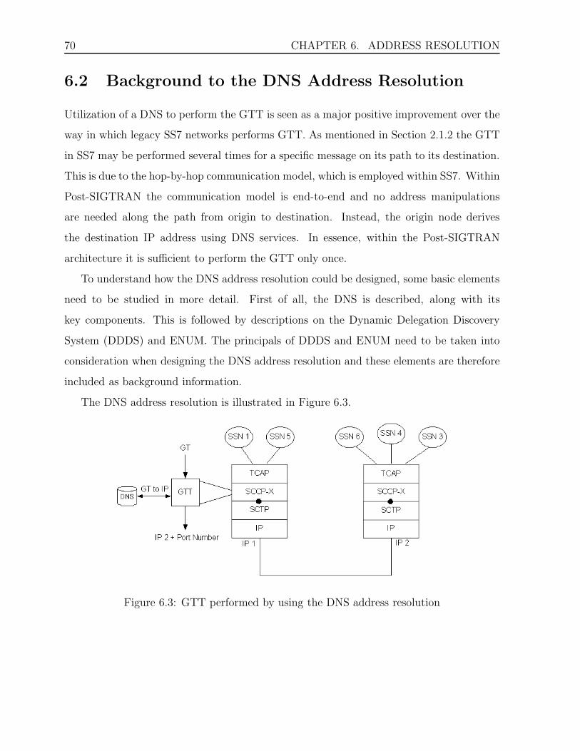
70 CHAPTER 6. ADDRESS RESOLUTION
6.2 Background to the DNS Address Resolution
Utilization of a DNS to perform the GTT is seen as a major positive improvement over the
way in which legacy SS7 networks performs GTT. As mentioned in Section 2.1.2 the GTT
in SS7 may be performed several times for a specific message on its path to its destination.
This is due to the hop-by-hop communication model, which is employed within SS7. Within
Post-SIGTRAN the communication model is end-to-end and no address manipulations
are needed along the path from origin to destination. Instead, the origin node derives
the destination IP address using DNS services. In essence, within the Post-SIGTRAN
architecture it is sufficient to perform the GTT only once.
To understand how the DNS address resolution could be designed, some basic elements
need to be studied in more detail. First of all, the DNS is described, along with its
key components. This is followed by descriptions on the Dynamic Delegation Discovery
System (DDDS) and ENUM. The principals of DDDS and ENUM need to be taken into
consideration when designing the DNS address resolution and these elements are therefore
included as background information.
The DNS address resolution is illustrated in Figure 6.3.
Figure 6.3: GTT performed by using the DNS address resolution

6.2. BACKGROUND TO THE DNS ADDRESS RESOLUTION 71
6.2.1 Domain Name System
The most common way to identify us human beings is by our names. On the other hand,
when information about us is stored in different kinds of databases, we are identified by
unique numbers. Even though it is easier for computers to handle the numeric names,
people prefer the more mnemonic, alphabetic names, which are a lot easier to remember.
Similarly, people also prefer to use the alphabetic names for Internet hosts.
To identify hosts we use their host names, which are mnemonic and therefore appreci-
ated by humans. The Internet however, is in reality based on IP addresses. These addresses
always consist of four bytes1 and have a rigid hierarchical structure, while host names can
consist of variable-length alphanumeric characters. Hence, the IP addresses are much sim-
pler to process by routers, and are therefore preferred in this context [11]. For example,
humans use the name www.example.com, but what the Internet routers actually require is
the address 194.236.25.6.
In order to bring together these different preferences, an Internet service that translates
host names to IP addresses is needed. This is the main task of the Domain Name System
(DNS). Thus, every time a client uses a host name, a DNS service must translate the name
to the corresponding IP address. Abstractly, the translation is carried out in the following
manner.
From the client’s perspective the DNS is a black box [11]. The client specifies the host
name and sends a DNS query message asking for the corresponding IP address. On many
Unix-based machines this is done by using the library routine gethostbyname(). After a
delay2, the client receives a DNS reply message containing the desired IP address. Although
the client may think that the DNS is a simple, straightforward translation service, it is
much more complex than that. The DNS system is, in fact, a network that consists of many
DNS servers. If one DNS server does not know how to translate a particular hostname, it
1Four bytes is the size of the IPv4 addresses that currently used.2The delay can range from milliseconds to tens of seconds.
72 CHAPTER 6. ADDRESS RESOLUTION
asks another one, and so on, until the correct IP address is returned. The DNS consist, of a
large number of name servers distributed around the globe, as well as an application-layer
protocol that specifies how the name servers and querying hosts communicate [11].
One important capability coupled to DNS is the caching service. After a DNS server
has performed a translation, the server caches this translation so that later requests can
be handled faster than the previous. What happens is that the name server reads the
stored information and does not have to perform any translation or search mechanisms
each time the name is resolved. Each cached entry is deleted periodically, according to its
time-to-live value.
More about the elements of the DNS is described below.
Elements of DNS
The DNS has three major components [17, 18]:
• The domain name space is the specification for a tree structured name space, while
resource records represent data associated with the names. Theoretically, all
DNS host names fit into a name hierarchy, or tree, known as the domain name space.
The data associated with individual host names is stored in the specific resource
records that can have different types depending on the information they hold.
• name servers are server programs employed to perform name-to-address mapping.
They hold the information about the tree’s structure. They can also set information
about any part of the domain tree.
• resolvers are programs that provide the interface to the client. Their task is to
extract information from name servers in response to the clients request. The client
accesses the domain system through a simple procedure call to a local resolver.

6.2. BACKGROUND TO THE DNS ADDRESS RESOLUTION 73
6.2.2 Dynamic Delegation Discovery System
According to [12, 13, 14, 15, 16], the Dynamic Delegation Discovery System is used to
implement lazy binding of string to data, in order to support dynamically configured
delegation systems. The major task of the DDDS is to perform mapping of a unique string
to data stored within a DDDS database by iteratively applying string transformation rules
until a terminal condition is reached.
The DDDS involves three key concepts: the algorithm, the DDDS applications and the
DDDS databases. These concepts are briefly described in the following sections.
The Algorithm
The DDDS algorithm is defined by RFC 3402 [16]. The algorithm is based on the concept
of ’rewrite rules’. A rewrite rule is a rule that is applied to a string to produce a new
rewrite rule or a final result string that is returned to the calling application. The rewrite
rules are collected into a DDDS rule database, and accessed by given unique keys.
The procedure of converting a string starts with the so-called ’first well known rule’.
The first well known rule, when applied to a string, transforms that string into new key that
can be used to retrieve a new rule from the rule database. This new rule is then reapplied
to the same original string and the cycle repeats itself until a terminating condition is
reached. The illustration of the algorithm is presented in Figure 6.4.
The DDDS Applications
No implementation of the DDDS algorithm can begin without an application specification,
as this is what provides the concrete instantiation details for the algorithm [14]. Without
an application the DDDS is nothing more than a general algorithm.
Each DDDS application must specify the key elements which are described below:
• The application unique string (aus) is the only string that the rewrite rules

74 CHAPTER 6. ADDRESS RESOLUTION
Figure 6.4: The DDDS Algorithm
will apply to. The string must have a regular structure and be unique within the
application.
• The first well known rule is the rule that, when applied to the AUS, produces
the first valid key. This rule must be specified so that the delegation process can
start.
• The expected output is what the output of the terminal condition should be.
• The ddds databases are the databases that are valid for the DDDS application.
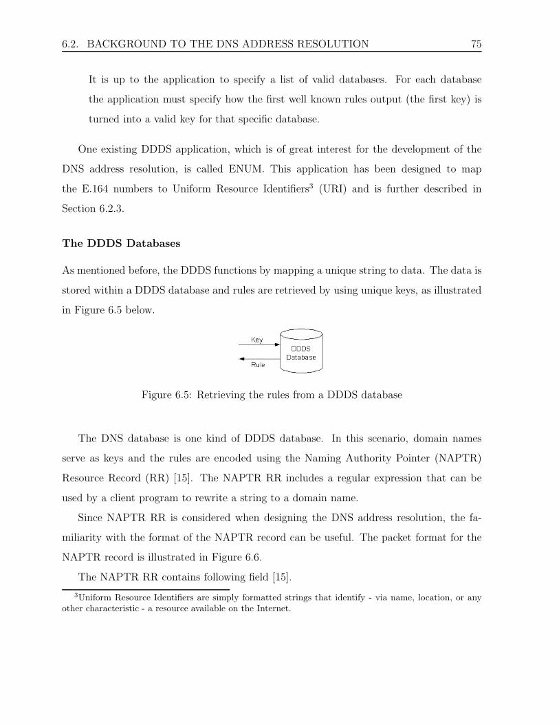
6.2. BACKGROUND TO THE DNS ADDRESS RESOLUTION 75
It is up to the application to specify a list of valid databases. For each database
the application must specify how the first well known rules output (the first key) is
turned into a valid key for that specific database.
One existing DDDS application, which is of great interest for the development of the
DNS address resolution, is called ENUM. This application has been designed to map
the E.164 numbers to Uniform Resource Identifiers3 (URI) and is further described in
Section 6.2.3.
The DDDS Databases
As mentioned before, the DDDS functions by mapping a unique string to data. The data is
stored within a DDDS database and rules are retrieved by using unique keys, as illustrated
in Figure 6.5 below.
Figure 6.5: Retrieving the rules from a DDDS database
The DNS database is one kind of DDDS database. In this scenario, domain names
serve as keys and the rules are encoded using the Naming Authority Pointer (NAPTR)
Resource Record (RR) [15]. The NAPTR RR includes a regular expression that can be
used by a client program to rewrite a string to a domain name.
Since NAPTR RR is considered when designing the DNS address resolution, the fa-
miliarity with the format of the NAPTR record can be useful. The packet format for the
NAPTR record is illustrated in Figure 6.6.
The NAPTR RR contains following field [15].
3Uniform Resource Identifiers are simply formatted strings that identify - via name, location, or anyother characteristic - a resource available on the Internet.

76 CHAPTER 6. ADDRESS RESOLUTION
Figure 6.6: The packet format for the NAPTR record.
• order: A 16 bit unsigned integer specifying the order in which the NAPTR records
must be processed in order to correctly represent the ordered list of rules. The
ordering is from lowest to highest.
• preference: A 16 bit unsigned integer that specifies the order in which NAPTR
record with equal order values should be processed, low numbers being processed
before high numbers.
• flags: A character-string containing flags to control the rewriting and interpretation
of the fields in the record. Flags are single characters that are individually specified
by applications. The applications must define which flags are terminal and which
ones are not.
• services: A character-string that specifies the service parameters applicable to this
delegation path. It is up to the applications to specify the values found in this field.
• regexp: A character-string containing a substitution expression that is applied to
the AUS in order to construct the next domain name to lookup.
• replacement: A domain name which is the next domain name to query if the rule
was not terminal.

6.2. BACKGROUND TO THE DNS ADDRESS RESOLUTION 77
6.2.3 ENUM
ENUM [4] is a DDDS application which specifies how a DNS databases can be used for stor-
age of E.164 numbers. More specifically, how a DNS can be used for identifying available
services connected to one E.164 number.
The domain ’e164.arpa’ is being populated in order to provide the infrastructure in DNS
for storage of E.164 numbers. In order to facilitate distributed operations, this domain is
divided into subdomains as illustrated in Figure 6.7.
Figure 6.7: The ’e164.arpa’ namespace
As described in the previous section a DDDS application must specify some key elements
in order to be meaningful. Below the ENUM specification of the key elements is stated.
• The application unique string is a fully qualified E.164 number minus any non-
digit characters except for the ’+’ character which appears in the beginning of a

78 CHAPTER 6. ADDRESS RESOLUTION
number. For example, the E.164 number could start out as ’+46-54-123456’ and end
up as the following AUS: ’+4654123456’.
• The first well known rule for this application is the identity rule. The output
of this rule is the same as the input. This is because the E.164 namespace and this
applications databases are organized in such a way that it is possible to go directly
from the E.164 number to the smallest granularity of the namespace. In the previous
example, the AUS is ’+4654123456’ and after applying the first well known rule, the
exact same string is produced: ’+4654123456’.
• The expected output of the last DDDS loop is a URI in its absolute form as it is
described in RFC 2396.
• The ddds database specified for this application is the DNS database. In this
database, the rewrite rules are contained in so-called NAPTR DNS Recourse Records
(RR), as specified in RFC 3403. The keys, that are used to access the database, are
encoded as domain names. This is illustrated in Figure 6.8 below.
Figure 6.8: Retrieving the rules from a DNS database
As the example above described, the string ’+4654123456’ was the result of the first
well known rule. This string will not work as a key for the DNS database, since the DNS
keys are encoded as domain names. Therefore, the string must be converted to a domain
name, using the following algorithm.
• Remove all non-digit characters; the string ’+4654123456’ becomes ’4654123456’.

6.2. BACKGROUND TO THE DNS ADDRESS RESOLUTION 79
• Put dots between each digit; the string ’4654123456’ becomes ’4.6.5.4.1.2.3.4.5.6’.
• Reverse the order of the digits; the string ’4.6.5.4.1.2.3.4.5.6’ becomes ’6.5.4.3.2.1.4.5.6.4’.
• Append the string ’.e164.arpa’ to the end of the string; ’6.5.4.3.2.1.4.5.6.4’ becomes
the domain name ’6.5.4.3.2.1.4.5.6.4.e164.arpa’.
This domain name is used to request NAPTR RR, which contain rewrite rules. When
the AUS is applied to these rules new domain names are produced. These domain names
may be the final results if the DDDS algorithm is finished. Though, if the algorithm is
not yet finished, the produced domain names are used to query other DNS databases until
the DDDS loop reaches the terminating condition and the DDDS algorithm is finished. In
Figure 6.9 below, an example of the DDDS algorithm is illustrated, with ENUM as the
DDDS application.

80 CHAPTER 6. ADDRESS RESOLUTION
Figure 6.9: An example of the DDDS algorithm with ENUM as the DDDS application
In the NAPTR RR, stored within the DNS database, there is a special field which
contains a flag that signals when the DDDS algorithm has finished. For this purpose, the
’u’ flag has been defined. When this flag is contained in a NAPTR RR, it means that the
rule is the last one and the expected output of this rule is a URI.
An NAPTR RR is illustrated in Figure 6.10 below. As the figure shows, several services

6.3. PROBLEM FORMULATION 81
can be connected to a specific E.164 number. The ENUM application retrieves the URIs
that are connected to a specific E.164 number and determines which of them is the most
suitable to use. For instance, as Figure 6.10 illustrates, the domain ’6.5.4.3.2.1.4.5.6.4.e164.arpa’
is preferably contacted by SIP. Secondly contacted by H.323 for voice and thirdly by SMTP
for messaging.
Figure 6.10: An example of a DNS NAPTR RR
6.3 Problem Formulation
The SCCP-X user that wants to send data identifies the destination by its GT value.
Within the prototype, this GT value is always considered to be an E.164 number. To be able
to forward the data to the underlying SCTP protocol, SCCP-X must perform the necessary
translation. The GT value of the destination must be mapped to the corresponding IP
address to enable the data transmission. To fully utilize the IP capabilities, this translation
should be accomplished by using the DNS services.
As described earlier, a DNS database stores data by means of domain names. Con-

82 CHAPTER 6. ADDRESS RESOLUTION
sequently, a DNS would not be able to understand a pure GT value. To overcome this
problem, the GT value must be converted into an element that a DNS understands, that
is a domain name.
The questions are, how can this conversion be accomplished and how can the final IP
address be obtained?
6.4 Design
As mentioned in the previous section, an E.164 number needs to be converted into an IP
address, to enable transmission of messages in the Post-SIGTRAN architecture. Since this
address resolution should be performed by a DNS server, the first step is to investigate if
E.164 numbers can be handled by DNS. As mentioned in Section 6.2.3, there is support
to store E.164 numbers in a DNS, by using the ’e.164.arpa’ namespace. Though, before
the E.164 number can be stored in a DNS it needs to be converted into a domain name,
so that the DNS can understand its structure. The algorithm used when performing this
conversion is described in Section 6.2.3. Basically, the E.164 number ’+46-54-123456’ is
converted into the following domain name: ’6.5.4.3.2.1.4.5.6.4.e164.arpa’. This domain
name can now be used to query a DNS which supports the e.164.arpa namespace. In the
ENUM DDDS application the specified output of such a query is a URI. Thus, the ENUM
application is a suitable starting point for the address resolution.
However, SCTP does not use URIs to address a destination, so the address resolution
needs to be further developed. The URI result from the first DNS query needs to be
translated into an IP address. This can simply be accomplished by using the most common
DNS lookup, the A record4.
4The RR of type A is the most common DNS RR which maps a domain name to an IP address

6.4. DESIGN 83
To summarize, two separate DNS queries must be made. The first query would map
the converted domain name to a URI and the second query would map the URI to an IP
address.
Figure 6.11: The DNS address resolution
The identity rule used by ENUM is found to be superfluous. According to the DDDS
standards, the first well known rule is used to produce the first valid key. This key should
be used to query a DDDS database. In the case when DNS is used as the DDDS database,
the key must be a valid domain name. Thus, according to the DDDS standardization
the first well known rule of the ENUM application should, when applied, convert a E.164
number to a valid domain name. Since ENUMs first well known rule does not produce a
domain name it does not fully conform to the DDDS standardization.
As mentioned above, ENUM is a good starting point when designing the DNS address
resolution. Thus, a new DDDS application that modifies the ENUM application needs to
be specified. First up, to make ENUM applicable for SS7, one possible solution is to add
an SS7 service for the specified E.164 number. This means that NAPTR RR needs to be
modified. To follow the already specified ENUM pattern, this service could be expressed
as ’E2U+ss7’, in a NAPTR RR. Since the needed information in the RR is the host name
of the destination node, the regular expression field for the SS7 service should contain this

84 CHAPTER 6. ADDRESS RESOLUTION
data. The extended ENUM example would then look like the one shown in Figure 6.12.
The added entry for the SS7 service is presented in bold style.
Figure 6.12: An SS7 entry added
As mentioned in Section 6.2.1, the DNS component that provides the interface to the
client is called the resolver. Since the objective is to enable the client SCCP-X to query a
GT value and receive an IP address in return, the DNS resolver needs to be modified.
After the resolver has received a query from SCCP-X, it will utilize the modified ENUM
application to convert the E.164 number to a host name. This conversion will be performed
in the traditional ENUM way. First, the E.164 number is converted into a valid domain
name which will be used to perform a NAPTR query. The DNS server will reply with all
NAPTR RR entries for the queried origin. To continue with the example from above, the
received result of the query would look like the one presented in Figure 6.12.
The next step for the application will be to separate the SS7 entry from the rest of
the result. The algorithm for accomplishing this task is not believed to constitute any
major problems. The key is to search after the entry with a service field containing the
’E2U+ss7’ service. Once the correct entry has been selected, the host name of the desti-
nation needs to be retrieved. That information is enclosed within the regular expression
field. The algorithm that selects the expression following after the ’ !.*$!ss7:’ is needed.
The implementation of such algorithm is believed to be rather simple. The resolved host
name will then be returned to the DNS resolver.

6.4. DESIGN 85
The remaining task of the resolver is the traditional DNS lookup. By sending an A
query for the obtained host name, the DNS resolver will receive the IP address of the
destination as the result. Consequently, this IP address will be returned to the SCCP-X
client.
To summarize, the steps of the described translation are illustrated in Figure 6.13.
Figure 6.13: The GT to IP address translation.
It is believed to be achievable to design a single DDDS application that supports all GT
types. The AUS for such application would be a fully qualified GT value, independent of
the type. The different types are assumed to require different algorithms to get converted
into valid domain named. The first well known rule for the application must therefore
posses the capacity to distinguish between different types in order to apply the suitable
conversion algorithm.
The delimitations concerning the address resolution are important to mention. A GT
value can only be mapped to a single IP address, while an IP address can be mapped to
several GT values. This delimitation simplifies the resolver mechanism. If this were not
the case, the resolver would have to choose from several IP addresses before returning an
address to the client.

86 CHAPTER 6. ADDRESS RESOLUTION
6.5 Implementation
One important step when implementing the DNS address resolution is to configure a DNS
server that supports the storage of E.164 numbers. From the beginning, the idea was
to install and configure BIND5 locally on one of the two nodes used within the prototype
network. After some research had been done, an already configured DNS server with E.164
support was found outside the prototype network. This DNS server has been used to test
some of the design ideas.
The implementation of the DNS address resolution has not yet been realized, it remains
for future work.
5Berkeley Internet Name Domain (BIND) is the most commonly used DNS server on the Internet,especially on Unix-like systems

Chapter 7
Conclusions
The most common standard for signaling networks is the SS7 network. Today, the SS7
network is made up of circuit-switched networks. However, due to the increasing availabil-
ity of IP networks, it is likely that the circuit-switched networks will be replaced in the
future. The conversion to the IP domain has already started. The first step to enable SS7
applications to run on top of IP networks, was to utilize the SIGTRAN architecture which
has been developed by the IETF. SIGTRAN has the capacity to transport SS7 messages
over IP, but it is unnecessary complex and does not fully utilize the IP technology. For
that reason, the Post-SIGTRAN architecture has been proposed. Post-SIGTRAN is meant
to make use of the additional capabilities of IP and still be simpler than SIGTRAN.
The main contributor to Post-SIGTRANs simplicity is that the Signaling Point Code
(SPC) addressing is excluded and only the Global Title (GT) addressing is utilized. GTs are
unique and adapted for international use. SPC are not unique and are therefore maintained
within each network and among networks. By excluding the SPC addressing, the flexibility
for cooperating networks and operators will increase and the Post-SIGTRANs architecture
will be less complex.
In the future, when operators start converging to all-IP networks, the Post-SIGTRAN
architecture is perceived to be the most efficient architecture. This is based on the fact
87

88 CHAPTER 7. CONCLUSIONS
that the IP networks will replace both telecommunication networks that are employed
today. Currently, the telecommunication network consists of the signaling network and the
network that carries the actual data. When the Post-SIGTRAN architecture gets deployed,
only one network will be needed which is assumed to result in operator savings. This is
based on the assumption that it should be less expensive to manage only one network. The
operator employees would only need to possess knowledge of how to maintain and develop
one network and since no separate signaling network will be needed, it is assumed that
some equipment cutbacks could be carried out.
This thesis has introduced a prototype for a new lightweight protocol which shall be
employed within the Post-SIGTRAN architecture. This protocol is meant to emulate
the primary services of SCCP in the traditional SS7 architecture, thus it has been called
SCCP-X.
To achieve the lightweightness, SCCP-X should utilize the already existing IP technol-
ogy. To further streamline and minimize the SCCP-X layer, it has been made dependent
on SCTP as the transport protocol. The goal is to take advantage of the services provided
by SCTP/IP and thereby remove any functional redundancy and slim the protocol stack.
By making SCCP-X lightweight, the development of the signaling technology is assumed
to be simplified. This is further assumed to result in faster releases and lower research and
development costs.
Since SCCP-X is an SCCP replacement protocol, the primary services of SCCP should
be supported by the new protocol. The connectionless service of SCCP was chosen as
the starting point for the prototype, supporting both unordered and ordered delivery of
messages. The ordered delivery was accomplished by a stream selection mechanism for
SCTP streams.
It is concluded that the stream selection mechanism can reuse the same elements utilized
by SCCP to provide the service of ordered delivery. These elements are the sequence control
parameter and the reference parameter specified by the user in the N UNITDATA req

89
primitive. Together, these parameters are used to indicate that a specific message requires
ordered delivery. All messages with the same reference value are sent onto the same SCTP
stream. The ordered delivery can then be provided by SCTP, fulfilling the goal to take
advantage of the services offered by SCTP. The stream selection mechanism corresponds to
the SLS mechanism used by the original SCCP where all messages with the same reference
value are sent onto the same link. The reutilization of the sequence control parameter and
the reference parameter is believed to emphasize the transparency of the SCCP-X protocol.
Another important task of SCCP is to provide an address translation mechanism, called
Global Title Translation (GTT). When SCCP receives a message from the upper layer, the
destination node is identified by its GT address. SCCP translates the GT into an address
that is comprehensible by the underlying circuit-switched networks. Similarly, SCCP-X
performs an address resolution to translate the GT into an address that is understandable
by the underlying IP networks. The result of the address resolution is naturally an IP
address and a port number, since in IP networks, these address elements are used to
route a message to the destination. Since SCCP-X should make use of the existing IP
technology, the new protocol should make use of the DNS services when performing the
address resolution.
Currently, the prototype performs the address resolution by the means of a preconfig-
ured file. Though, efforts have been made to explore the feasibility to use the DNS services
to perform the address resolution. It is concluded that two DNS queries are needed. The
first query would translate a GT into a host name and the second query would translate
the host name to an IP address. For the second query, a basic A record would be used.
However, to accomplish the first translation, a new DDDS application needs to be speci-
fied. The ENUM DDDS application specifies how a DNS database can be used for storage
of E.164 numbers and is therefore considered to be a suitable starting point for the address
resolution. It is believed that quite simple modifications to the existing ENUM application
will be sufficient to perform the first translation, from a GT to a host name. One modi-

90 CHAPTER 7. CONCLUSIONS
fication that has been considered is to define and add a new SS7 service to make ENUM
applicable for SS7. Further, some elements of the ENUM DDDS application need to be
modified. The Application Unique String (AUS) is the element that can be transformed
into a key, when the first well known rule is applied to it. The key can then be used to
query a database. The AUS of the enhanced ENUM application should be a fully qualified
GT. The first well known rule of the enhanced application should, when applied, convert
the GT into a valid domain name. The domain name can then be used to send a NAPTR
query to a DNS database. The answer to the NAPTR query is the host name, which shall
be used for the second query to retrieve the IP address.
The address resolution within Post-SIGTRAN is more efficient than the GTT within
legacy SS7 networks. Due to the hop-by-hop communication model, employed within
SS7, the GTT may be performed several times for a specific message on its path to its
destination. This is not the case within Post-SIGTRAN, which employs an end-to-end
communication model where the address resolution is performed only once, at the origin
node.
One of the objectives with this thesis was to examine the feasibility to construct a
protocol with reduced complexity, which would enable already existing SS7 applications to
run on top of IP networks. With regard to the restrictions that have been made during the
project, the accomplished prototype is believed to constitute a solid base for future work.

Chapter 8
Future Work
The next step in evolving the SCCP-X protocol would be to implement the DNS address
resolution. This will replace the current preconfigured address resolution mechanism. Since
it has been found that the slightly modified ENUM application can be used for transla-
tion of E.164 numbers, the next step would be to further examine how the new DDDS
application can be realized. During the project, efforts were made to test the DNS sup-
port for storage of E.164 numbers by using the system call nslookup. The obtained results
appeared promising. Therefore, the next step should be to study the functionalities of
nslookup, along with the implementation of an ENUM application, to get ideas of how the
GT to IP translation could be accomplished.
When a functioning DNS address resolution is designed, it is of importance to expand
the scope of GT types which may be used within SCCP-X. A mechanism to convert E.212
and E.214 numbers to domain names should be investigated. It is believed that these
GT types, when converted, could be supported in a similar way as E.164 numbers are
supported by ENUM.
When the GT to IP address resolution is performed, the local DNS server will cache
the entries of the queries. Each time the client wants to contact the same destination,
the conversion from the GT to the domain name must be performed and at least two
91

92 CHAPTER 8. FUTURE WORK
queries must be made. Therefore, it would be convenient if the client had the ability
to locally cache the retrieved IP addresses of its destinations. A caching mechanism is
assumed to improve performance significantly and it is believed that the development of
such mechanism is worth investing in.
Since the prototype is developed for a simple prototype network, static association es-
tablishment was considered. Even though SCTP associations do not cost much, static es-
tablishment may be inefficient in large networks. Especially when destination IP addresses
are not cached locally and at least two DNS queries must be made for all destinations.
Thus, dynamic association establishment should be incorporated. It is believed that the
transition will be quite straightforward and without major problems. When dynamic as-
sociation establishment gets developed, associations will be established when needed. The
question is if they must be disconnected when no longer needed, since they do not cost
resources. This issue needs to be discussed. If it is concluded that inactive associations
must be torn down, an activity mechanism that detects if an association is no longer used
needs to be implemented.
Using dynamic association establishment implies that the management module should
not order SCCP-X to start all associations with the MM ORDER reg (START ALL ASSOC)
primitive, which is the case in the current prototype. Instead, SCCP-X will establish an
association to the specified destination first after the higher layer requests to send infor-
mation. In other words, after the N UNITDATA req primitive is received, SCCP-X will
establish an association to the specified destination. Though, if an association already
exists towards the specific destination, it will be reused.
To properly emulate the original SCCP behaviour, the N NOTICE ind primitive must
be implemented. At the time, if an error occurs, the failed destination returns the affected
message back to the origin SCCP-X. What remains is to forward the returned message
back to the upper layer. For this purpose, the N NOTICE ind should be implemented.
Additionally, an SCCP equivalent service is left for future work, namely the CO service.

93
This means that before data can be transferred between two SPs, a connection must be
established between them. When evolving SCCP-X to support the CO service, additional
primitives need to be explored and implemented.


Chapter 9
Experiences and Problems
The extent of this thesis has been a far greater then anything else we have ever done before.
As expected, it took a long time to get a good grasp of the task. We did not have any
experience of SS7 and SIGTRAN, so the whole concept of signaling felt very complex.
We had to do a lot of research before we even were ready to start designing the SCCP-X
protocol. At some points during this work, we had a little too much literature to read and
it was not always easy to sort out the information that was essential for the thesis. Often,
it was tough to stop reading and start applying the gained knowledge. Even though the
task sometimes felt overwhelming, the knowledge that we can handle a project of such
magnitude is very valuable to us.
It was a challenge to understand all the primitives that were needed within the proto-
type. Since the surrounding modules must remain intact, it is of great importance that
the primitives sent to them are constructed properly. Each primitive contains a number
of parameters, which all play a significant role within communication between different
modules. Sometimes, parameters had ambiguous names that made it hard to figure out
what their actual function was. In broad outlines, it is the primitives that build up the
protocol skeleton. They had to be implemented before any protocol functionalities could
be considered. Even though it was absolutely necessary, the process of constructing the
95

96 CHAPTER 9. EXPERIENCES AND PROBLEMS
skeleton felt too time demanding. It would have been much more stimulating to use that
time to implement a well-functioning DNS address resolution. But without a functioning
skeleton, no protocol would exist and we would probably lack all the valuable knowledge
and comprehension that we have earned during this process.
The lack of experience made it hard to state the realistic delimitations of the work. From
the beginning, we thought that it would be possible to create a test environment where no
errors could occur. Since SCCP-X do not alone constitute the Post-SIGTRAN signaling,
several modules affect the outcome of the testing and the error free environment was
impossible to implement. In due time, we realized that some error handling was necessary
to implement. This required the time that was initially allocated for the development of
some valuable protocol functionalities.
One issue, which has followed us throughout the whole project, was the inability to
perform the continuous testing of the prototype. We would have preferred to test the
prototype step-by-step during the implementation, but we did not have the access to the
necessary test application. It would have been easier to detect simple mistakes and in that
way avoid serious errors. Instead, we tested the whole module at once, which was quite
risky. On the other hand, it was perhaps a bit naive to believe that it would be easy to
test the prototype primitive-by-primitive. It would probably have required a lot of time to
set up the test environment suitable for such testing. Even though it felt tough to write
thousands of lines of code without knowing that the prototype would really work, the late
test phase has probably saved us some valuable time.
On the whole, this project has been a great experience which has given us the oppor-
tunity to grow as designers and developers.

References
[1] Common Parts. Internal webpage.
[2] Protocol Dictionary. http://www.protocols.com.
[3] Jim Darroch. Introduction to Sigtran. White Paper.
[4] P. Faltstrom. The E.164 to Uniform Resource Identifiers (URI) Dynamic DelegationDiscovery System (DDDS) Application (ENUM). RFC 3761, IETF, April 2004.
[5] ITU-T. Specifications of Signalling System No. 7 - Signalling Connection ControlPart: Definition and function of Signalling Connection Control Part messages. ITU-TRecommendation Q.712, ITU, July 1996.
[6] ITU-T. Specifications of Signalling System No. 7 - Signalling Connection ControlPart: Functional description of the Signalling Connection Control Part. ITU-T Rec-ommendation Q.711, ITU, July 1996.
[7] ITU-T. Specifications of Signalling System No. 7 - Signalling Connection ControlPart: Signalling Connection Control Part formats and codes. ITU-T RecommendationQ.713, ITU, July 1996.
[8] ITU-T. Specifications of Signalling System No. 7 - Signalling Connection Control Part:Signalling Connection Control Part Procedures. ITU-T Recommendation Q.714, ITU,July 1996.
[9] ITU-T. Specifications of Signalling System No. 7 - Signalling Connection ControlPart: Signalling Connection Control Part user guide. ITU-T Recommendation Q.715,ITU, July 1996.
[10] A. L. Caro Jr., J. R. Iyengar, P. D. Amer, S. Ladha, G. J. Heinz II, and K. C. Shah.Sctp: A Proposed Standard for Robust Internet Data Transport. IEEE Computer,pages 56–63, November 2003.
[11] J. F. Kurose and K. W. Ross. Computer Networking: A Top-Down Approach Featur-ing the Internet. Addison Wesley, 1 edition, 2001.
97

98 REFERENCES
[12] M. Mealling. Dynamic Delegation Discovery System (DDDS) Part Five: URI.ARPAAssignment Procedures. RFC 3405, IETF, October 2002.
[13] M. Mealling. Dynamic Delegation Discovery System (DDDS) Part Four: The UniformResource Identifiers (URI) Resolution Application. RFC 3404, IETF, October 2002.
[14] M. Mealling. Dynamic Delegation Discovery System (DDDS) Part One: The Com-prehensive DDDS. RFC 3401, IETF, October 2002.
[15] M. Mealling. Dynamic Delegation Discovery System (DDDS) Part Three: The DomainName System (DNS) Database. RFC 3403, IETF, October 2002.
[16] M. Mealling. Dynamic Delegation Discovery System (DDDS) Part Two: The Algo-rithm. RFC 3402, IETF, October 2002.
[17] P. Mockapetris. Domain Names - Concepts and Facilities. RFC 1034, IETF, November1987.
[18] P. Mockapetris. Domain Names - Implementation and Specification. RFC 1035, IETF,November 1987.
[19] Guy Redmill. An Introduction to SS7. 2001. White Paper.
[20] Travis Russell. Signaling System #7. McGraw-Hill, Inc., 1 edition, 1995.
[21] Ericsson Signalling. SCCP ANSI/ITU/TTC/Chinese R9, Functional Specification.Internal Document 1/155 17-CAA 901 437 Uen, Ericsson AB, June 2003.
[22] Ericsson Signalling. SCTP IETF, Functional Specification. Internal Document 15517-CAA 901 548 Uen, Ericsson AB, March 2004.
[23] Ericsson SS7. Management Interface R6 ANSI/ITU/TTC, Functional Specification.Internal Document 155 17-CAA 201 30 Uen, Ericsson Infotech AB, March 2001.
[24] R. Stewart, Q. Xie, Motorola, K. Morneault, C. Sharp, Cisco, H. Schwarzbauer,Siemens, T. Taylor, Nortel Networks, I. Rytina, Ericsson, M. Kalla, Telcordia,L. Zhang, UCLA, V. Paxson, and ACIRI. Stream Control Transmission Protocol.RFC 2960, IETF, October 2000.

Appendix A
Abbreviations
ATM Asynchronous Transfer Mode
AUS Application Unique String
BIND Berkeley Internet Name Domain
CAP CAMEL Customized Application
CL Connectionless
CO Connection-Oriented
CP Common Parts
CS Circuit Switched
DCP Destination Point Code
DDDS Dynamic Delegation Discovery System
DNS Domain Name System
GT Global Title
GTT Title Translation
HLR Home Location Register
HOL Head Of Line
IMSI International Mobile Subscriber Identity
IN Intelligent Network
99

100 APPENDIX A. ABBREVIATIONS
IP Internet Protocol
ISDN Integrated Services Digital Network
ISUP ISDN User Part
LUDT Long Unitdata
MAP Mobile Application Parts
MCC Mobile Country Code
MM Management Module
MNC Mobile Network Code
MSC Mobile Switching Centre
MSIN Mobile Station Identification Number
MTP Message Transfer Part
NAPTR Naming Authority Pointer
OPC Originating Point Code
PSTN Public Switched Telephone Network
QoS Quality of Service
RR Resource Record
SCCP Signaling Connection Control Part
SCP Service Control Point
SCTP Stream Control Transmission Protocol
SLS Signaling Link Selection
SP Signaling Points
SPC Signaling Point Code
SS7 Signaling System No.7
SSN Sub-System Number
SSP Service Switching Point
TCAP Transaction Capabilities Application Part
TCP Transmission Control Protocol

101
TDM Time Division Multiplexing
TUP Telephone User Part
UA User Adaptation
UDT Unitdata
URI Uniform Resource Identifier
VLR Visitor Location Register
XUDT Extended Unitdata