Embed Size (px)
Citation preview
SCCP-US-WH-US_en-30 | 98-123900.01 | Version 3.0 AMERICAN ENGLISH
Maintenance ManualSUNNY CENTRAL 500CP-US/CA / 500CP-US/CA 600V / 630CP-US/CA / 720CP-US/CA / 750CP-US/CA / 800CP-US/CA / 850CP-US/CA / 900CP-US/CA
Legal Provisions SMA America, LLC
2 SCCP-US-WH-US_en-30 Maintenance Manual
Legal ProvisionsCopyright © 2014 SMA America, LLC. All rights reserved.No part of this document may be reproduced, stored in a retrieval system, or transmitted, in any form or by any means, be it electronic, mechanical, photographic, magnetic or otherwise, without the prior written permission of SMA America, LLC.Neither SMA America, LLC nor SMA Solar Technology Canada Inc. makes representations, express or implied, with respect to this documentation or any of the equipment and/or software it may describe, including (with no limitation) any implied warranties of utility, merchantability, or fitness for any particular purpose. All such warranties are expressly disclaimed. Neither SMA America, LLC nor its distributors or dealers nor SMA Solar Technology Canada Inc. nor its distributors or dealers shall be liable for any indirect, incidental, or consequential damages under any circumstances.(The exclusion of implied warranties may not apply in all cases under some statutes, and thus the above exclusion may not apply.)Specifications are subject to change without notice. Every attempt has been made to make this document complete, accurate and up-to-date. Readers are cautioned, however, that SMA America, LLC and SMA Solar Technology Canada Inc. reserve the right to make changes without notice and shall not be responsible for any damages, including indirect, incidental or consequential damages, caused by reliance on the material presented, including, but not limited to, omissions, typographical errors, arithmetical errors or listing errors in the content material.TrademarksAll trademarks are recognized, even if not explicitly identified as such. A lack of identification does not mean that a product or symbol is not trademarked.The Bluetooth® word mark and logos are registered trademarks owned by Bluetooth SIG, Inc. and any use of these marks by SMA America, LLC and SMA Solar Technology Canada Inc. is under license.Modbus® is a registered trademark of Schneider Electric and is licensed by the Modbus Organization, Inc.QR Code® is a registered trademark of DENSO WAVE INCORPORATED.Phillips® and Pozidriv® are registered trademarks of Phillips Screw Company.Torx® is a registered trademark of Acument Global Technologies, Inc.
SMA America, LLC3801 N. Havana Street
Denver, CO 80239 U.S.A.
SMA Solar Technology Canada Inc.2425 Matheson Blvd. E
7th FloorMississauga, ON L4W 5K4
Canada
SMA America, LLC Important Safety Instructions
Maintenance Manual SCCP-US-WH-US_en-30 3
Important Safety InstructionsSAVE THESE INSTRUCTIONSThis manual contains important instructions for the following products:
• Sunny Central 500CP-US/CA (SC 500CP-US-10)• Sunny Central 500CP-US/CA 600V (SC 500CP-US-10 600V)• Sunny Central 630CP-US/CA (SC 630CP-US-10)• Sunny Central 720CP-US/CA (SC 720CP-US-10)• Sunny Central 750CP-US/CA (SC 750CP-US-10)• Sunny Central 800CP-US/CA (SC 800CP-US-10)• Sunny Central 850CP-US/CA (SC 850CP-US-10)• Sunny Central 900CP-US/CA (SC 900CP-US-10)
This manual must be followed during installation and maintenance.
The product is designed and tested in accordance with international safety requirements, but as with all electrical and electronic equipment, certain precautions must be observed when installing and/or operating the product. To reduce the risk of personal injury and to ensure the safe installation and operation of the product, you must carefully read and follow all instructions, cautions and warnings in this manual.
Warnings in this documentA warning describes a hazard to equipment or personnel. It calls attention to a procedure or practice, which, if not correctly performed or adhered to, could result in damage to or destruction of part or all of the SMA equipment and/or other equipment connected to the SMA equipment or personal injury.Maintenance ManualSymbol Description
DANGER indicates a hazardous situation which, if not avoided, will result in death or serious injury.WARNING indicates a hazardous situation which, if not avoided, could result in death or serious injury.CAUTION indicates a hazardous situation which, if not avoided, could result in minor or moderate injury.NOTICE is used to address practices not related to personal injury.
Warnings on this product SMA America, LLC
4 SCCP-US-WH-US_en-30 Maintenance Manual
Warnings on this productThe following symbols are used as product markings with the following meanings.
General Warnings
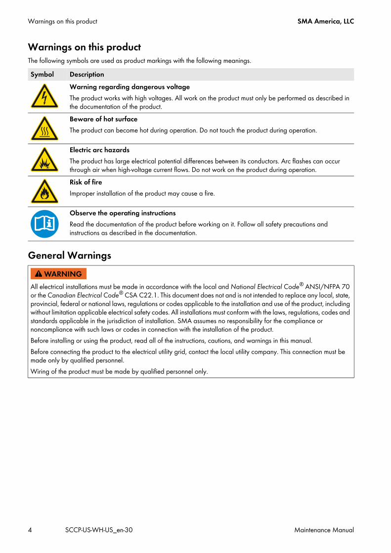
Symbol DescriptionWarning regarding dangerous voltageThe product works with high voltages. All work on the product must only be performed as described in the documentation of the product.Beware of hot surfaceThe product can become hot during operation. Do not touch the product during operation.
Electric arc hazardsThe product has large electrical potential differences between its conductors. Arc flashes can occur through air when high-voltage current flows. Do not work on the product during operation.Risk of fireImproper installation of the product may cause a fire.
Observe the operating instructionsRead the documentation of the product before working on it. Follow all safety precautions and instructions as described in the documentation.
All electrical installations must be made in accordance with the local and National Electrical Code® ANSI/NFPA 70 or the Canadian Electrical Code® CSA C22.1. This document does not and is not intended to replace any local, state, provincial, federal or national laws, regulations or codes applicable to the installation and use of the product, including without limitation applicable electrical safety codes. All installations must conform with the laws, regulations, codes and standards applicable in the jurisdiction of installation. SMA assumes no responsibility for the compliance or noncompliance with such laws or codes in connection with the installation of the product.Before installing or using the product, read all of the instructions, cautions, and warnings in this manual.Before connecting the product to the electrical utility grid, contact the local utility company. This connection must be made only by qualified personnel.Wiring of the product must be made by qualified personnel only.
SMA America, LLC Table of Contents
Maintenance Manual SCCP-US-WH-US_en-30 5
Table of Contents1 Information on this Document. . . . . . . . . . . . . . . . . . . . . . . . . . . . . . . . . . . . . . . . . . . . . . . . . . . . . 7
1.1 Validity . . . . . . . . . . . . . . . . . . . . . . . . . . . . . . . . . . . . . . . . . . . . . . . . . . . . . . . . . . . . . . . . . . . . . . . . . . . . . . 71.2 Target Group . . . . . . . . . . . . . . . . . . . . . . . . . . . . . . . . . . . . . . . . . . . . . . . . . . . . . . . . . . . . . . . . . . . . . . . . . 71.3 Additional Information . . . . . . . . . . . . . . . . . . . . . . . . . . . . . . . . . . . . . . . . . . . . . . . . . . . . . . . . . . . . . . . . . . 71.4 Symbols . . . . . . . . . . . . . . . . . . . . . . . . . . . . . . . . . . . . . . . . . . . . . . . . . . . . . . . . . . . . . . . . . . . . . . . . . . . . . 71.5 Typographies . . . . . . . . . . . . . . . . . . . . . . . . . . . . . . . . . . . . . . . . . . . . . . . . . . . . . . . . . . . . . . . . . . . . . . . . . 81.6 Nomenclature. . . . . . . . . . . . . . . . . . . . . . . . . . . . . . . . . . . . . . . . . . . . . . . . . . . . . . . . . . . . . . . . . . . . . . . . . 81.7 Abbreviations . . . . . . . . . . . . . . . . . . . . . . . . . . . . . . . . . . . . . . . . . . . . . . . . . . . . . . . . . . . . . . . . . . . . . . . . . 9
2 Safety . . . . . . . . . . . . . . . . . . . . . . . . . . . . . . . . . . . . . . . . . . . . . . . . . . . . . . . . . . . . . . . . . . . . . . . 102.1 Intended Use . . . . . . . . . . . . . . . . . . . . . . . . . . . . . . . . . . . . . . . . . . . . . . . . . . . . . . . . . . . . . . . . . . . . . . . . 102.2 Safety Precautions . . . . . . . . . . . . . . . . . . . . . . . . . . . . . . . . . . . . . . . . . . . . . . . . . . . . . . . . . . . . . . . . . . . . 122.3 Personal Protective Equipment . . . . . . . . . . . . . . . . . . . . . . . . . . . . . . . . . . . . . . . . . . . . . . . . . . . . . . . . . . . 152.4 Symbols on the inverter . . . . . . . . . . . . . . . . . . . . . . . . . . . . . . . . . . . . . . . . . . . . . . . . . . . . . . . . . . . . . . . . 15
3 Product Description . . . . . . . . . . . . . . . . . . . . . . . . . . . . . . . . . . . . . . . . . . . . . . . . . . . . . . . . . . . . 163.1 Plant Overview . . . . . . . . . . . . . . . . . . . . . . . . . . . . . . . . . . . . . . . . . . . . . . . . . . . . . . . . . . . . . . . . . . . . . . . 163.2 Design of the Inverter . . . . . . . . . . . . . . . . . . . . . . . . . . . . . . . . . . . . . . . . . . . . . . . . . . . . . . . . . . . . . . . . . . 183.3 Type Label . . . . . . . . . . . . . . . . . . . . . . . . . . . . . . . . . . . . . . . . . . . . . . . . . . . . . . . . . . . . . . . . . . . . . . . . . . 183.4 Symbols on the Product . . . . . . . . . . . . . . . . . . . . . . . . . . . . . . . . . . . . . . . . . . . . . . . . . . . . . . . . . . . . . . . . 193.5 Schematic Diagram . . . . . . . . . . . . . . . . . . . . . . . . . . . . . . . . . . . . . . . . . . . . . . . . . . . . . . . . . . . . . . . . . . . 19
4 Information on Maintenance . . . . . . . . . . . . . . . . . . . . . . . . . . . . . . . . . . . . . . . . . . . . . . . . . . . . 204.1 Maintenance Intervals . . . . . . . . . . . . . . . . . . . . . . . . . . . . . . . . . . . . . . . . . . . . . . . . . . . . . . . . . . . . . . . . . 204.2 Spare Parts . . . . . . . . . . . . . . . . . . . . . . . . . . . . . . . . . . . . . . . . . . . . . . . . . . . . . . . . . . . . . . . . . . . . . . . . . . 20
5 Maintenance with DC, AC and Control Voltage Present . . . . . . . . . . . . . . . . . . . . . . . . . . . . . . 215.1 Reading the Replacement Interval Meter . . . . . . . . . . . . . . . . . . . . . . . . . . . . . . . . . . . . . . . . . . . . . . . . . . . 215.2 Reading Error Messages and Warnings . . . . . . . . . . . . . . . . . . . . . . . . . . . . . . . . . . . . . . . . . . . . . . . . . . . 215.3 Checking the DC Contactor in Units without the Integrated DC Switch . . . . . . . . . . . . . . . . . . . . . . . . . . . . 215.4 Checking the AC Circuit Breaker . . . . . . . . . . . . . . . . . . . . . . . . . . . . . . . . . . . . . . . . . . . . . . . . . . . . . . . . . 23
6 Disconnecting the Inverter. . . . . . . . . . . . . . . . . . . . . . . . . . . . . . . . . . . . . . . . . . . . . . . . . . . . . . . 257 Maintenance in Disconnected State . . . . . . . . . . . . . . . . . . . . . . . . . . . . . . . . . . . . . . . . . . . . . . . 28
7.1 Safety . . . . . . . . . . . . . . . . . . . . . . . . . . . . . . . . . . . . . . . . . . . . . . . . . . . . . . . . . . . . . . . . . . . . . . . . . . . . . . 287.2 Removing the Panels . . . . . . . . . . . . . . . . . . . . . . . . . . . . . . . . . . . . . . . . . . . . . . . . . . . . . . . . . . . . . . . . . . 297.3 Cleaning the Ventilation Plate. . . . . . . . . . . . . . . . . . . . . . . . . . . . . . . . . . . . . . . . . . . . . . . . . . . . . . . . . . . . 297.4 Cleaning the Air Duct and Insect Screens. . . . . . . . . . . . . . . . . . . . . . . . . . . . . . . . . . . . . . . . . . . . . . . . . . . 307.5 Cleaning the Interior . . . . . . . . . . . . . . . . . . . . . . . . . . . . . . . . . . . . . . . . . . . . . . . . . . . . . . . . . . . . . . . . . . . 337.6 Checking the Fuses . . . . . . . . . . . . . . . . . . . . . . . . . . . . . . . . . . . . . . . . . . . . . . . . . . . . . . . . . . . . . . . . . . . . 337.7 Checking the Surge Arrester . . . . . . . . . . . . . . . . . . . . . . . . . . . . . . . . . . . . . . . . . . . . . . . . . . . . . . . . . . . . . 347.8 Checking the Screw Connection of the Power Cabling . . . . . . . . . . . . . . . . . . . . . . . . . . . . . . . . . . . . . . . . 357.9 Checking the Safety Labels. . . . . . . . . . . . . . . . . . . . . . . . . . . . . . . . . . . . . . . . . . . . . . . . . . . . . . . . . . . . . . 37
7.9.1 Inverter without Integrated DC Switch . . . . . . . . . . . . . . . . . . . . . . . . . . . . . . . . . . . . . . . . . . . . . . . . . . . . . . . .377.9.2 Inverter with Integrated DC Switch . . . . . . . . . . . . . . . . . . . . . . . . . . . . . . . . . . . . . . . . . . . . . . . . . . . . . . . . . .39
7.10 Checking the Door Seals . . . . . . . . . . . . . . . . . . . . . . . . . . . . . . . . . . . . . . . . . . . . . . . . . . . . . . . . . . . . . . . 41
SMA America, LLC Table of Contents
Maintenance Manual SCCP-US-WH-US_en-30 6
7.11 Checking the Latches, Door Stops and Hinges. . . . . . . . . . . . . . . . . . . . . . . . . . . . . . . . . . . . . . . . . . . . . . . 427.12 Checking the Switch Cabinet for Corrosion . . . . . . . . . . . . . . . . . . . . . . . . . . . . . . . . . . . . . . . . . . . . . . . . . 427.13 Mounting the Panels . . . . . . . . . . . . . . . . . . . . . . . . . . . . . . . . . . . . . . . . . . . . . . . . . . . . . . . . . . . . . . . . . . . 43
8 Connecting the Control Voltage . . . . . . . . . . . . . . . . . . . . . . . . . . . . . . . . . . . . . . . . . . . . . . . . . . 449 Maintenance when Control Voltage is Present . . . . . . . . . . . . . . . . . . . . . . . . . . . . . . . . . . . . . . 45
9.1 Safety . . . . . . . . . . . . . . . . . . . . . . . . . . . . . . . . . . . . . . . . . . . . . . . . . . . . . . . . . . . . . . . . . . . . . . . . . . . . . 459.2 Checking the Integrated DC Switch . . . . . . . . . . . . . . . . . . . . . . . . . . . . . . . . . . . . . . . . . . . . . . . . . . . . . . . 469.3 Checking the Heating Element, Hygrostat and Fan . . . . . . . . . . . . . . . . . . . . . . . . . . . . . . . . . . . . . . . . . . . 48
10 Contact . . . . . . . . . . . . . . . . . . . . . . . . . . . . . . . . . . . . . . . . . . . . . . . . . . . . . . . . . . . . . . . . . . . . . . 5011 Revision History . . . . . . . . . . . . . . . . . . . . . . . . . . . . . . . . . . . . . . . . . . . . . . . . . . . . . . . . . . . . . . . 51
SMA America, LLC 1 Information on this Document
Maintenance Manual SCCP-US-WH-US_en-30 7
1 Information on this DocumentThis section provides important information on how to use this document and how to work with the inverter. Among other things, this document specifies the inverters for which this document is valid and the target group for which it has been written.
1.1 ValidityThis document is valid for the following inverters:
• Sunny Central 500CP-US/CA (SC 500CP-US-10)• Sunny Central 500CP-US/CA 600V (SC 500CP-US-10 600V)• Sunny Central 630CP-US/CA (SC 630CP-US-10)• Sunny Central 720CP-US/CA (SC 720CP-US-10)• Sunny Central 750CP-US/CA (SC 750CP-US-10)• Sunny Central 800CP-US/CA (SC 800CP-US-10)• Sunny Central 850CP-US/CA (SC 850CP-US-10)• Sunny Central 900CP-US/CA (SC 900CP-US-10)
This document describes the maintenance of the inverter.
1.2 Target GroupThis document is intended for qualified persons. Only qualified personnel are allowed to perform the tasks described in this document.Qualified persons have received appropriate training and have demonstrated the ability and knowledge to install, operate, and perform maintenance on the device.Qualified persons have been trained in how to deal with the dangers and risks associated with installing electrical installations and possess all the necessary knowledge for averting danger.Qualified persons are aware of the obligation to wear Hazard Risk Category 2 personal protective equipment and always comply with the general safety regulations for dealing with electric voltage.Qualified persons have been trained in how to deal with the dangers and risks associated with installing electrical installations as specified in 29 CFR, Chapter XVII, Part 1910 (OSHA), NEC, and NFPA 70E, and possess all the necessary background for averting danger. There must be written documentation of their training.
1.3 Additional InformationYou will find further information in the download area of www.SMA-America.com.
1.4 Symbols
Information Document typeInstallation Requirements for Sunny Central 500CP-US / 500CP-US 600V / 630CP-US 720CP-US / 750CP-US / 800CP-US / 850CP-US / 900CP-US
Technical Information
Medium-voltage transformers - Important Requirements for Medium-Voltage Transformers and Transformers for Auxiliary Power Supply for SUNNY CENTRAL CP-US Series Inverters
Technical Information
Sunny Central Communication Controller Technical Information
Symbol ExplanationInformation that is important for a specific topic or goal, but is not safety-relevant
1 Information on this Document SMA America, LLC
8 SCCP-US-WH-US_en-30 Maintenance Manual
1.5 Typographies
1.6 NomenclatureThe following nomenclature is used in this document:
Indicates a requirement for meeting a specific goal Desired result A problem that could occur
Typography Usage Examplebold • Display messages
• Elements on a user interface• Parameters• Terminals• Slots• Elements to be selected• Elements to be entered
• Select the parameter ExlTrfErrEna and set to Off.
• Select the tab Parameters.
Complete designation Designation in this documentSMA America Production, LLC SMASMA Solar Technology Canada Inc. SMASunny Central of the CP-US production series Sunny Central or inverterSunny Central Communication Controller SC-COM
Symbol Explanation
SMA America, LLC 1 Information on this Document
Maintenance Manual SCCP-US-WH-US_en-30 9
1.7 AbbreviationsIn this document, abbreviations are used at certain points. In the following table, you will find the full designation and an explanation, where applicable.Abbreviations Designation ExplanationAC Alternating Current -DC Direct Current -GFDI Ground Fault Detection Interruption -IP Internet Protocol -OF Optical Fiber -MPP Maximum Power Point -MSL Mean Sea Level -PC Personal Computer -PE Protective Earth Protective conductorPV Photovoltaics -
2 Safety SMA America, LLC
10 SCCP-US-WH-US_en-30 Maintenance Manual
2 Safety In this section, you will find general safety precautions which you must observe whenever working on the Sunny Central inverter. Pay special attention to these sections to avoid personal injury and property damage.
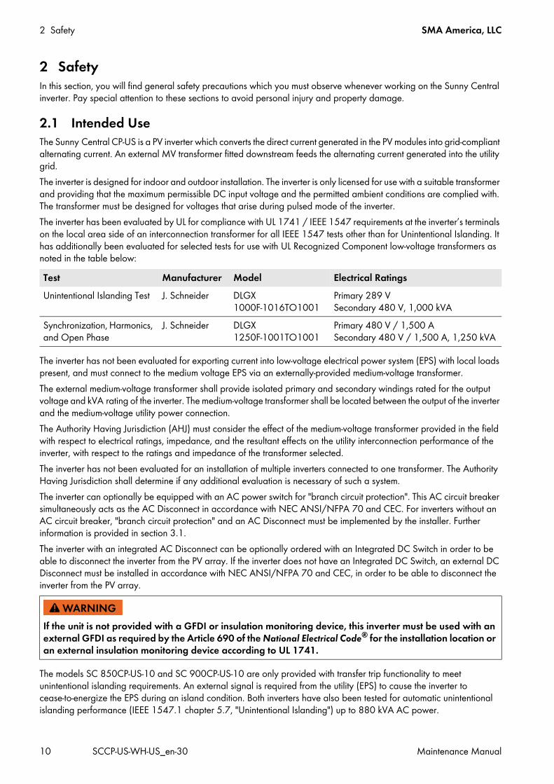
2.1 Intended Use The Sunny Central CP-US is a PV inverter which converts the direct current generated in the PV modules into grid-compliant alternating current. An external MV transformer fitted downstream feeds the alternating current generated into the utility grid.The inverter is designed for indoor and outdoor installation. The inverter is only licensed for use with a suitable transformer and providing that the maximum permissible DC input voltage and the permitted ambient conditions are complied with. The transformer must be designed for voltages that arise during pulsed mode of the inverter.The inverter has been evaluated by UL for compliance with UL 1741 / IEEE 1547 requirements at the inverter’s terminals on the local area side of an interconnection transformer for all IEEE 1547 tests other than for Unintentional Islanding. It has additionally been evaluated for selected tests for use with UL Recognized Component low-voltage transformers as noted in the table below:
The inverter has not been evaluated for exporting current into low-voltage electrical power system (EPS) with local loads present, and must connect to the medium voltage EPS via an externally-provided medium-voltage transformer.The external medium-voltage transformer shall provide isolated primary and secondary windings rated for the output voltage and kVA rating of the inverter. The medium-voltage transformer shall be located between the output of the inverter and the medium-voltage utility power connection.The Authority Having Jurisdiction (AHJ) must consider the effect of the medium-voltage transformer provided in the field with respect to electrical ratings, impedance, and the resultant effects on the utility interconnection performance of the inverter, with respect to the ratings and impedance of the transformer selected.The inverter has not been evaluated for an installation of multiple inverters connected to one transformer. The Authority Having Jurisdiction shall determine if any additional evaluation is necessary of such a system.The inverter can optionally be equipped with an AC power switch for "branch circuit protection". This AC circuit breaker simultaneously acts as the AC Disconnect in accordance with NEC ANSI/NFPA 70 and CEC. For inverters without an AC circuit breaker, "branch circuit protection" and an AC Disconnect must be implemented by the installer. Further information is provided in section 3.1.The inverter with an integrated AC Disconnect can be optionally ordered with an Integrated DC Switch in order to be able to disconnect the inverter from the PV array. If the inverter does not have an Integrated DC Switch, an external DC Disconnect must be installed in accordance with NEC ANSI/NFPA 70 and CEC, in order to be able to disconnect the inverter from the PV array.
The models SC 850CP-US-10 and SC 900CP-US-10 are only provided with transfer trip functionality to meet unintentional islanding requirements. An external signal is required from the utility (EPS) to cause the inverter to cease-to-energize the EPS during an island condition. Both inverters have also been tested for automatic unintentional islanding performance (IEEE 1547.1 chapter 5.7, "Unintentional Islanding") up to 880 kVA AC power.
Test Manufacturer Model Electrical RatingsUnintentional Islanding Test J. Schneider DLGX
1000F-1016TO1001Primary 289 V Secondary 480 V, 1,000 kVA
Synchronization, Harmonics, and Open Phase
J. Schneider DLGX 1250F-1001TO1001
Primary 480 V / 1,500 A Secondary 480 V / 1,500 A, 1,250 kVA
If the unit is not provided with a GFDI or insulation monitoring device, this inverter must be used with an external GFDI as required by the Article 690 of the National Electrical Code® for the installation location or an external insulation monitoring device according to UL 1741.
SMA America, LLC 2 Safety
Maintenance Manual SCCP-US-WH-US_en-30 11
The outdoor version of the inverter corresponds to UL 1741 "Type 3R" and can also be operated in rain, sleet, and snow.The indoor version corresponds to UL 1741 "Type 1" and is only licensed for installation in electrical equipment rooms.Only persons fulfilling all of the skills for the target group may work on or with theinverter.Intended use also includes reading the product documentation and observing all safety precautions.All work on the inverter must be performed using appropriate tools and in compliance with the ESD protection regulations.Suitable Hazard Risk Category 2 personal protective equipment is to be worn by all persons working on or with the inverter.Unauthorized persons may not operate the inverter and must keep at a distance from the inverter.No reconstruction, modification or installation of additional components may be carried out on the inverter without the express consent of SMA America, LLC.The inverter must not be operated with its doors open.The inverter must not be opened when it is raining or when humidity exceeds 95%.The inverter must not be operated with any technical defects.For safety reasons, it is forbidden to modify the product or install components that are not explicitly recommended or distributed by SMA.Only use the inverter in accordance with the information provided in the enclosed documentation. Any other application may cause personal injury or property damage.The enclosed documentation is an integral part of this product.
• Read and observe the documentation.• Keep the documentation in a convenient place for future reference.
2 Safety SMA America, LLC
12 SCCP-US-WH-US_en-30 Maintenance Manual
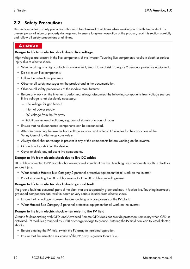
2.2 Safety PrecautionsThis section contains safety precautions that must be observed at all times when working on or with the product. To prevent personal injury or property damage and to ensure long-term operation of the product, read this section carefully and follow all safety precautions at all times.
Danger to life from electric shock due to live voltageHigh voltages are present in the live components of the inverter. Touching live components results in death or serious injury due to electric shock.
• When working in a high contact-risk environment, wear Hazard Risk Category 2 personal protective equipment.• Do not touch live components.• Follow the instructions precisely.• Observe all safety messages on the product and in the documentation.• Observe all safety precautions of the module manufacturer.• Before any work on the inverter is performed, always disconnect the following components from voltage sources
if live voltage is not absolutely necessary:– Line voltage for grid feed-in– Internal power supply– DC voltage from the PV array– Additional external voltages, e.g. control signals of a control room
• Ensure that no disconnected components can be reconnected.• After disconnecting the inverter from voltage sources, wait at least 15 minutes for the capacitors of the
Sunny Central to discharge completely.• Always check that no voltage is present in any of the components before working on the inverter.• Ground and short-circuit the device.• Cover or shield any adjacent live components.
Danger to life from electric shock due to live DC cablesDC cables connected to PV modules that are exposed to sunlight are live. Touching live components results in death or serious injury.
• Wear suitable Hazard Risk Category 2 personal protective equipment for all work on the inverter.• Prior to connecting the DC cables, ensure that the DC cables are voltage-free.
Danger to life from electric shock due to ground faultIf a ground fault has occurred, parts of the plant that are supposedly grounded may in fact be live. Touching incorrectly grounded components can result in death or very serious injuries from electric shock.
• Ensure that no voltage is present before touching any components of the PV plant.• Wear Hazard Risk Category 2 personal protective equipment for all work on the inverter.
Danger to life from electric shock when entering the PV fieldGround-fault monitoring with GFDI and Advanced Remote GFDI does not provide protection from injury when GFDI is activated. PV modules grounded by GFDI discharge voltage to ground. Entering the PV field can lead to lethal electric shocks.
• Before entering the PV field, switch the PV array to insulated operation.• Ensure that the insulation resistance of the PV array is greater than 1 k Ω .
SMA America, LLC 2 Safety
Maintenance Manual SCCP-US-WH-US_en-30 13
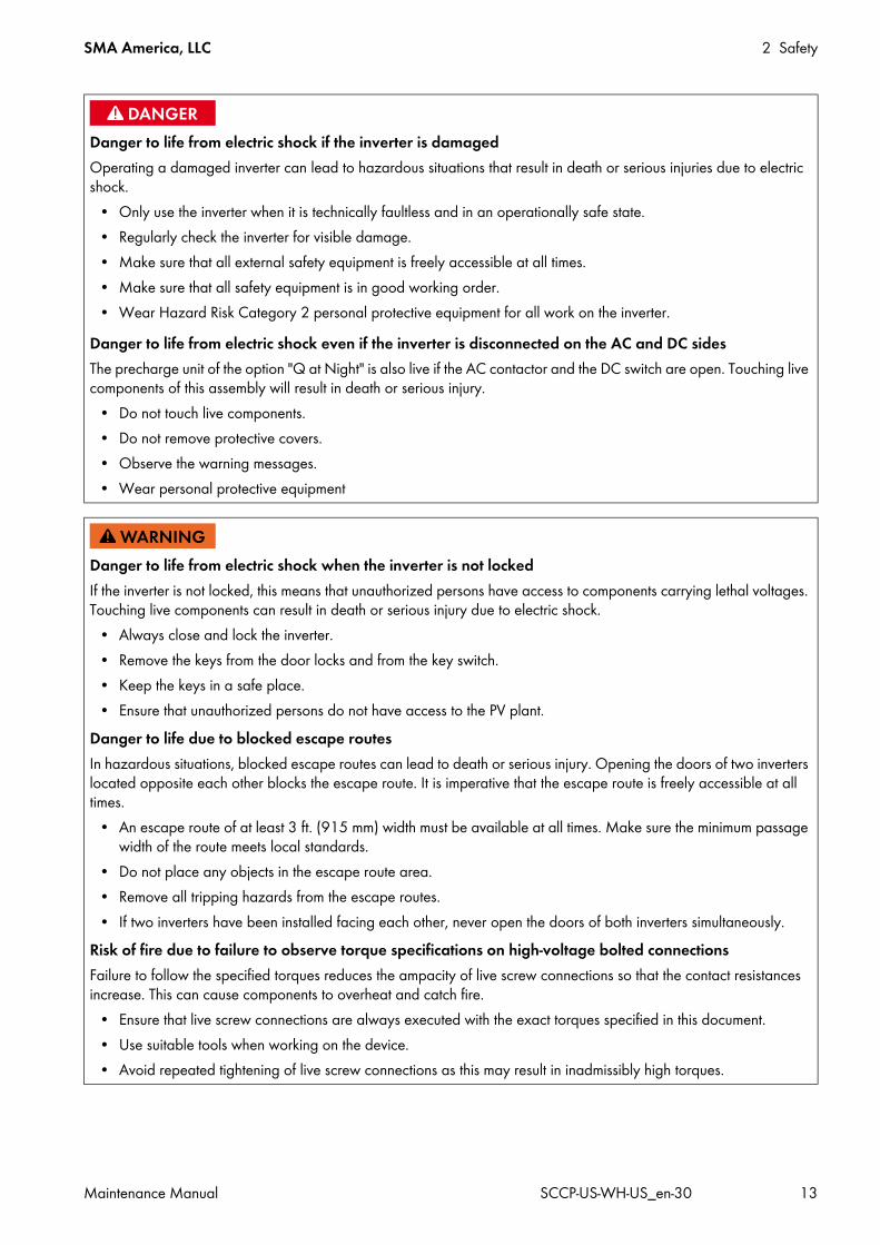
Danger to life from electric shock if the inverter is damagedOperating a damaged inverter can lead to hazardous situations that result in death or serious injuries due to electric shock.
• Only use the inverter when it is technically faultless and in an operationally safe state.• Regularly check the inverter for visible damage.• Make sure that all external safety equipment is freely accessible at all times.• Make sure that all safety equipment is in good working order.• Wear Hazard Risk Category 2 personal protective equipment for all work on the inverter.
Danger to life from electric shock even if the inverter is disconnected on the AC and DC sidesThe precharge unit of the option "Q at Night" is also live if the AC contactor and the DC switch are open. Touching live components of this assembly will result in death or serious injury.
• Do not touch live components.• Do not remove protective covers.• Observe the warning messages.• Wear personal protective equipment
Danger to life from electric shock when the inverter is not lockedIf the inverter is not locked, this means that unauthorized persons have access to components carrying lethal voltages. Touching live components can result in death or serious injury due to electric shock.
• Always close and lock the inverter.• Remove the keys from the door locks and from the key switch.• Keep the keys in a safe place.• Ensure that unauthorized persons do not have access to the PV plant.
Danger to life due to blocked escape routesIn hazardous situations, blocked escape routes can lead to death or serious injury. Opening the doors of two inverters located opposite each other blocks the escape route. It is imperative that the escape route is freely accessible at all times.
• An escape route of at least 3 ft. (915 mm) width must be available at all times. Make sure the minimum passage width of the route meets local standards.
• Do not place any objects in the escape route area.• Remove all tripping hazards from the escape routes.• If two inverters have been installed facing each other, never open the doors of both inverters simultaneously.
Risk of fire due to failure to observe torque specifications on high-voltage bolted connectionsFailure to follow the specified torques reduces the ampacity of live screw connections so that the contact resistances increase. This can cause components to overheat and catch fire.
• Ensure that live screw connections are always executed with the exact torques specified in this document.• Use suitable tools when working on the device.• Avoid repeated tightening of live screw connections as this may result in inadmissibly high torques.
2 Safety SMA America, LLC
14 SCCP-US-WH-US_en-30 Maintenance Manual
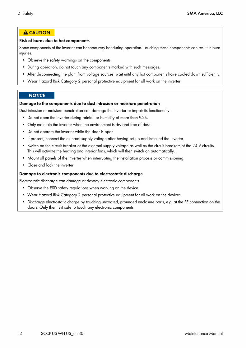
Risk of burns due to hot componentsSome components of the inverter can become very hot during operation. Touching these components can result in burn injuries.
• Observe the safety warnings on the components.• During operation, do not touch any components marked with such messages.• After disconnecting the plant from voltage sources, wait until any hot components have cooled down sufficiently.• Wear Hazard Risk Category 2 personal protective equipment for all work on the inverter.
Damage to the components due to dust intrusion or moisture penetrationDust intrusion or moisture penetration can damage the inverter or impair its functionality.
• Do not open the inverter during rainfall or humidity of more than 95%.• Only maintain the inverter when the environment is dry and free of dust.• Do not operate the inverter while the door is open.• If present, connect the external supply voltage after having set up and installed the inverter.• Switch on the circuit breaker of the external supply voltage as well as the circuit breakers of the 24 V circuits.
This will activate the heating and interior fans, which will then switch on automatically.• Mount all panels of the inverter when interrupting the installation process or commissioning.• Close and lock the inverter.
Damage to electronic components due to electrostatic dischargeElectrostatic discharge can damage or destroy electronic components.
• Observe the ESD safety regulations when working on the device.• Wear Hazard Risk Category 2 personal protective equipment for all work on the devices.• Discharge electrostatic charge by touching uncoated, grounded enclosure parts, e.g. at the PE connection on the
doors. Only then is it safe to touch any electronic components.
SMA America, LLC 2 Safety
Maintenance Manual SCCP-US-WH-US_en-30 15
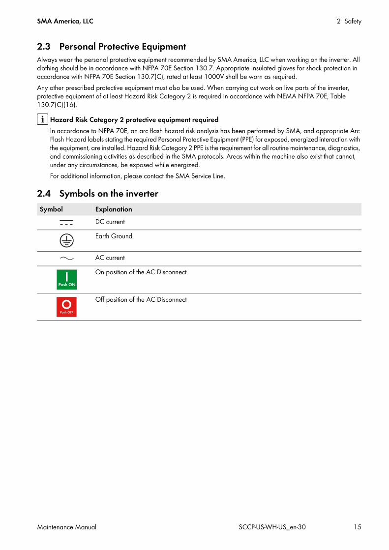
2.3 Personal Protective EquipmentAlways wear the personal protective equipment recommended by SMA America, LLC when working on the inverter. All clothing should be in accordance with NFPA 70E Section 130.7. Appropriate Insulated gloves for shock protection in accordance with NFPA 70E Section 130.7(C), rated at least 1000V shall be worn as required.Any other prescribed protective equipment must also be used. When carrying out work on live parts of the inverter, protective equipment of at least Hazard Risk Category 2 is required in accordance with NEMA NFPA 70E, Table 130.7(C)(16).
2.4 Symbols on the inverter
Hazard Risk Category 2 protective equipment requiredIn accordance to NFPA 70E, an arc flash hazard risk analysis has been performed by SMA, and appropriate Arc Flash Hazard labels stating the required Personal Protective Equipment (PPE) for exposed, energized interaction with the equipment, are installed. Hazard Risk Category 2 PPE is the requirement for all routine maintenance, diagnostics, and commissioning activities as described in the SMA protocols. Areas within the machine also exist that cannot, under any circumstances, be exposed while energized. For additional information, please contact the SMA Service Line.
Symbol ExplanationDC currentEarth Ground
AC currentOn position of the AC Disconnect
Off position of the AC Disconnect
3 Product Description SMA America, LLC
16 SCCP-US-WH-US_en-30 Maintenance Manual
3 Product DescriptionThis section will give you an overview of the inverter and its components.
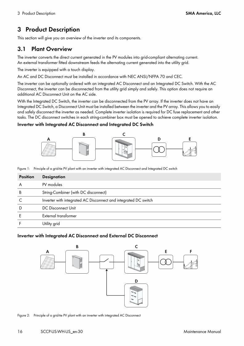
3.1 Plant OverviewThe inverter converts the direct current generated in the PV modules into grid-compliant alternating current. An external transformer fitted downstream feeds the alternating current generated into the utility grid.The inverter is equipped with a touch display.An AC and DC Disconnect must be installed in accordance with NEC ANSI/NFPA 70 and CEC.The inverter can be optionally ordered with an integrated AC Disconnect and an Integrated DC Switch. With the AC Disconnect, the inverter can be disconnected from the utility grid simply and safely. This option does not require an additional AC Disconnect Unit on the AC side.With the Integrated DC Switch, the inverter can be disconnected from the PV array. If the inverter does not have an Integrated DC Switch, a Disconnect Unit must be installed between the inverter and the PV array. This allows you to easily and safely disconnect the inverter as needed. Complete inverter isolation is required for DC fuse replacement and other tasks. The DC disconnect switches in each string-combiner box must be opened to achieve complete inverter isolation.Inverter with Integrated AC Disconnect and Integrated DC Switch
Figure 1: Principle of a grid-tie PV plant with an inverter with integrated AC Disconnect and Integrated DC switch
Inverter with Integrated AC Disconnect and External DC Disconnect
Figure 2: Principle of a grid-tie PV plant with an inverter with integrated AC Disconnect
Position DesignationA PV modulesB String-Combiner (with DC disconnect)C Inverter with integrated AC Disconnect and integrated DC switchD DC Disconnect UnitE External transformerF Utility grid
SMA America, LLC 3 Product Description
Maintenance Manual SCCP-US-WH-US_en-30 17
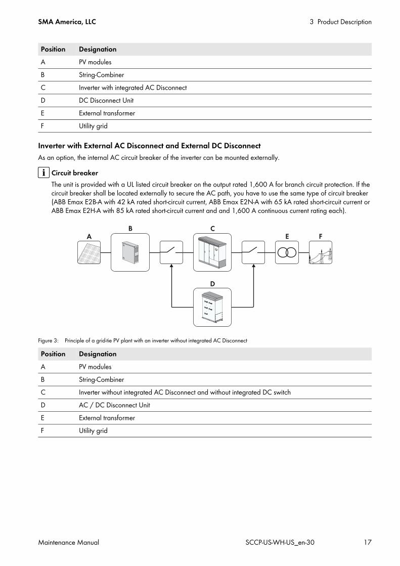
Inverter with External AC Disconnect and External DC DisconnectAs an option, the internal AC circuit breaker of the inverter can be mounted externally.
Figure 3: Principle of a grid-tie PV plant with an inverter without integrated AC Disconnect
Position DesignationA PV modulesB String-CombinerC Inverter with integrated AC DisconnectD DC Disconnect UnitE External transformerF Utility grid
Circuit breakerThe unit is provided with a UL listed circuit breaker on the output rated 1,600 A for branch circuit protection. If the circuit breaker shall be located externally to secure the AC path, you have to use the same type of circuit breaker (ABB Emax E2B-A with 42 kA rated short-circuit current, ABB Emax E2N-A with 65 kA rated short-circuit current or ABB Emax E2H-A with 85 kA rated short-circuit current and and 1,600 A continuous current rating each).
Position DesignationA PV modulesB String-CombinerC Inverter without integrated AC Disconnect and without integrated DC switchD AC / DC Disconnect UnitE External transformerF Utility grid
3 Product Description SMA America, LLC
18 SCCP-US-WH-US_en-30 Maintenance Manual
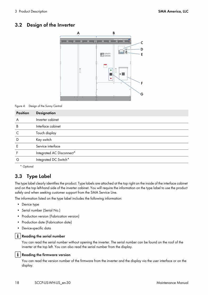
3.2 Design of the Inverter
Figure 4: Design of the Sunny Central
3.3 Type LabelThe type label clearly identifies the product. Type labels are attached at the top right on the inside of the interface cabinet and on the top left-hand side of the inverter cabinet. You will require the information on the type label to use the product safely and when seeking customer support from the SMA Service Line.The information listed on the type label includes the following information:
• Device type• Serial number (Serial No.)• Production version (Fabrication version)• Production date (Fabrication date)• Device-specific data
Position DesignationA Inverter cabinetB Interface cabinetC Touch displayD Key switchE Service interfaceF Integrated AC Disconnect*
* Optional
G Integrated DC Switch*
Reading the serial numberYou can read the serial number without opening the inverter. The serial number can be found on the roof of the inverter at the top left. You can also read the serial number from the display.
Reading the firmware versionYou can read the version number of the firmware from the inverter and the display via the user interface or on the display.
SMA America, LLC 3 Product Description
Maintenance Manual SCCP-US-WH-US_en-30 19
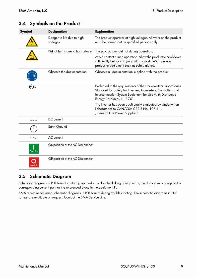
3.4 Symbols on the Product
3.5 Schematic DiagramSchematic diagrams in PDF format contain jump marks. By double clicking a jump mark, the display will change to the corresponding current path or the referenced place in the equipment list.SMA recommends using schematic diagrams in PDF format during troubleshooting. The schematic diagrams in PDF format are available on request. Contact the SMA Service Line.
Symbol Designation ExplanationDanger to life due to high voltages
The product operates at high voltages. All work on the product must be carried out by qualified persons only.
Risk of burns due to hot surfaces The product can get hot during operation.Avoid contact during operation. Allow the product to cool down sufficiently before carrying out any work. Wear personal protective equipment such as safety gloves.
Observe the documentation. Observe all documentation supplied with the product.
Evaluated to the requirements of the Underwriters Laboratories Standard for Safety for Inverters, Converters, Controllers and Interconnection System Equipment for Use With Distributed Energy Resources, UL 1741.The inverter has been additionally evaluated by Underwriters Laboratories to CAN/CSA C22.2 No. 107.1-1, „General Use Power Supplies“.
DC currentEarth Ground
AC currentOn position of the AC Disconnect
Off position of the AC Disconnect
4 Information on Maintenance SMA America, LLC
20 SCCP-US-WH-US_en-30 Maintenance Manual
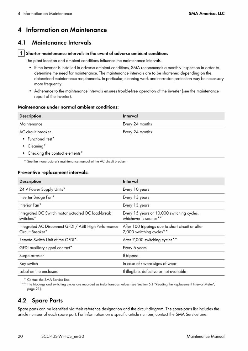
4 Information on Maintenance4.1 Maintenance Intervals
Maintenance under normal ambient conditions:
Preventive replacement intervals:
4.2 Spare PartsSpare parts can be identified via their reference designation and the circuit diagram. The spare-parts list includes the article number of each spare part. For information on a specific article number, contact the SMA Service Line.
Shorter maintenance intervals in the event of adverse ambient conditionsThe plant location and ambient conditions influence the maintenance intervals.
• If the inverter is installed in adverse ambient conditions, SMA recommends a monthly inspection in order to determine the need for maintenance. The maintenance intervals are to be shortened depending on the determined maintenance requirements. In particular, cleaning work and corrosion protection may be necessary more frequently.
• Adherence to the maintenance intervals ensures trouble-free operation of the inverter (see the maintenance report of the inverter).
Description IntervalMaintenance Every 24 monthsAC circuit breaker
• Functional test*• Cleaning*• Checking the contact elements*
* See the manufacturer's maintenance manual of the AC circuit breaker
Every 24 months
Description Interval24 V Power Supply Units*
* Contact the SMA Service Line.
Every 10 yearsInverter Bridge Fan* Every 13 yearsInterior Fan* Every 13 yearsIntegrated DC Switch motor actuated DC load-break switches*
Every 15 years or 10,000 switching cycles, whichever is sooner**
Integrated AC Disconnect GFDI / ABB High-Performance Circuit Breaker*
After 100 trippings due to short circuit or after 7,000 switching cycles**
** The trippings and switching cycles are recorded as instantaneous values (see Section 5.1 "Reading the Replacement Interval Meter", page 21).
Remote Switch Unit of the GFDI* After 7,000 switching cycles**GFDI auxiliary signal contact* Every 6 yearsSurge arrester If trippedKey switch In case of severe signs of wearLabel on the enclosure If illegible, defective or not available
SMA America, LLC 5 Maintenance with DC, AC and Control Voltage Present
Maintenance Manual SCCP-US-WH-US_en-30 21
5 Maintenance with DC, AC and Control Voltage Present5.1 Reading the Replacement Interval Meter
1. Log into the user interface.2. Enter the password in the appropriate field on the homepage and confirm with [Login].3. Select Data > Device.4. Select
A list of all existing device types appears.5. Select the device type Sunny Central.
A list appears containing all existing devices of this type.6. Select the desired device from the list.7. Select the tab Spot values.8. Check the following meters and compare them with the replacement intervals (see Section 4.1, page 20):
– Number of GFDI trippings in the instantaneous value CntGfdiTripSw. If replacement of the GFDI is necessary, the error message 7714 will appear on the display.
– Number of switching cycles of the Remote Switch Unit of the GFDI in the instantaneous value CntGfdiSw.– Number of switching cycles of the Integrated DC Switch in the instantaneous value CntDCSw.– If the corresponding instantaneous value equals or is greater than the replacement interval of the component,
replace the component. Contact the SMA Service Line.
5.2 Reading Error Messages and WarningsUse the service interface on the outside of the interface cabinet to connect a PC (see inverter operating manual). Procedure:
• If an error occurs, read off the error on the display or the user interface and remedy the error:• Select the warning symbol in the navigation line of the touch display.
The touch display lists the error number, delay time, error message and the necessary corrective measure to eliminate the error.
5.3 Checking the DC Contactor in Units without the Integrated DC Switch
Electric shock due to live voltageHigh voltages are present in the inverter and its components. Touching live components results in death or serious injury. Depending on the function, some maintenance work must be carried out with voltage present.
• Wear Hazard Risk Category 2 personal protective equipment.• Always perform work in compliance with the regulations specified in 29 CFR, Chapter XVII, Part 1910 (OSHA),
NEC, and NFPA 70E. • Do not touch any live components in the inverter or the medium-voltage grid.• Follow the instructions precisely.• Observe safety messages.
5 Maintenance with DC, AC and Control Voltage Present SMA America, LLC
22 SCCP-US-WH-US_en-30 Maintenance Manual
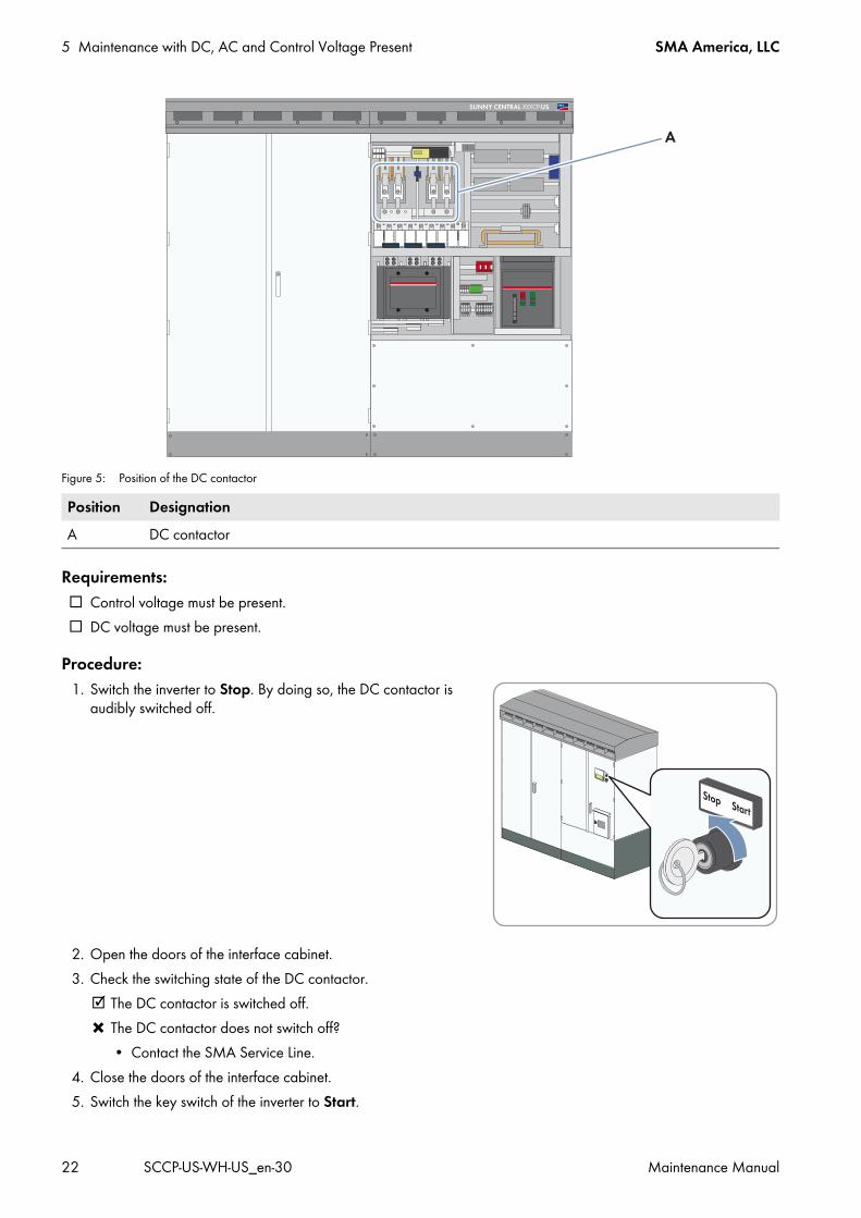
Figure 5: Position of the DC contactor
Requirements: Control voltage must be present. DC voltage must be present.
Procedure:1. Switch the inverter to Stop. By doing so, the DC contactor is
audibly switched off.
2. Open the doors of the interface cabinet.3. Check the switching state of the DC contactor.
The DC contactor is switched off. The DC contactor does not switch off?
• Contact the SMA Service Line.4. Close the doors of the interface cabinet.5. Switch the key switch of the inverter to Start.
Position DesignationA DC contactor
SMA America, LLC 5 Maintenance with DC, AC and Control Voltage Present
Maintenance Manual SCCP-US-WH-US_en-30 23
6. Open the doors of the interface cabinet.7. Check the switching state of the DC contactor.
The DC contactor is switched on. The DC contactor does not switch on?
• Contact the SMA Service Line.8. Switch the inverter to Stop.9. Test the switching process three times. Check three times whether the DC contactor has switched.
10. Close the doors of the interface cabinet.
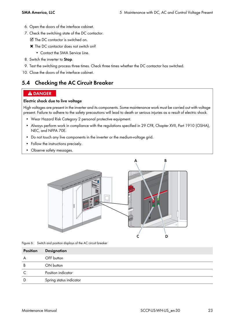
5.4 Checking the AC Circuit Breaker
Figure 6: Switch and position displays of the AC circuit breaker
Electric shock due to live voltageHigh voltages are present in the inverter and its components. Some maintenance work must be carried out with voltage present. Failure to adhere to the safety precautions will lead to death or serious injuries as a result of electric shock.
• Wear Hazard Risk Category 2 personal protective equipment.• Always perform work in compliance with the regulations specified in 29 CFR, Chapter XVII, Part 1910 (OSHA),
NEC, and NFPA 70E. • Do not touch any live components in the inverter or the medium-voltage grid.• Follow the instructions precisely.• Observe safety messages.
Position DesignationA OFF buttonB ON buttonC Position indicatorD Spring status indicator
5 Maintenance with DC, AC and Control Voltage Present SMA America, LLC
24 SCCP-US-WH-US_en-30 Maintenance Manual
Additionally required maintenance material (not included in the scope of delivery): A testing device approved by the manufacturer of the AC circuit breaker (e.g. TT1 from ABB).
Procedure:1. Open the doors of the interface cabinet.2. Use the testing device to check whether the AC circuit breaker is ready for operation (instructions for testing are
included in the documentation of the testing device).If a fault occurs during the test, contact the SMA Service Line.
3. Close the doors of the interface cabinet.
SMA America, LLC 6 Disconnecting the Inverter
Maintenance Manual SCCP-US-WH-US_en-30 25
6 Disconnecting the InverterPrior to performing any work on the inverter, disconnect it from any voltage sources as described in this section.
Danger to life from electric shock due to live voltageHigh voltages are present in the live components of the inverter. Touching live components results in death or serious injury due to electric shock.
• When working in a high contact-risk environment, wear personal protective equipment.• Always perform work in compliance with the regulations specified in 29 CFR, Chapter XVII, Part 1910 (OSHA),
NEC, and NFPA 70E.• Do not touch live components.• Follow the instructions precisely.• Observe all safety messages on the product and in the documentation.• Observe all safety precautions of the module manufacturer.• Before any work on the inverter is performed, always disconnect the following components from voltage sources
if live voltage is not absolutely necessary:– Line voltage for grid feed-in– Internal power supply– DC voltage from the PV array– Additional external voltages, e.g. control signals of a control room
• Ensure that no disconnected components can be reconnected.• After disconnecting the inverter from voltage sources, wait at least 15 minutes for the capacitors of the
Sunny Central to discharge completely.• Always check that no voltage is present in any of the components before working on the inverter.• Ground and short-circuit the device.• Cover or shield any adjacent live components.
Danger to life from electric shock due to live DC cablesDC cables connected to PV modules that are exposed to sunlight are live. Touching live components results in death or serious injury.
• Wear Hazard Risk Category 2 personal protective equipment for all work on the inverter.• Prior to connecting the DC cables, ensure that the DC cables are voltage-free.
Danger to life from electric shock due to ground faultIf a ground fault has occurred, parts of the plant that are supposedly grounded may in fact be live. Touching incorrectly grounded components can result in death or very serious injuries from electric shock.
• Ensure that no voltage is present before touching any components of the PV plant.• Wear Hazard Risk Category 2 personal protective equipment for all work on the inverter.
Danger to life from electric shock when entering the PV fieldGround-fault monitoring with GFDI and Advanced Remote GFDI does not provide protection from injury when GFDI is activated. PV modules grounded by GFDI discharge voltage to ground. Entering the PV field can lead to lethal electric shocks.
• Before entering the PV field, switch the PV array to insulated operation.• Ensure that the insulation resistance of the PV array is greater than 1 k Ω .
6 Disconnecting the Inverter SMA America, LLC
26 SCCP-US-WH-US_en-30 Maintenance Manual
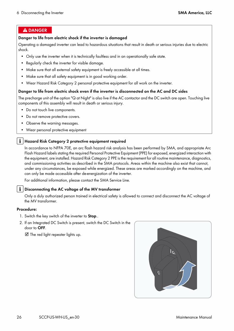
Procedure: 1. Switch the key switch of the inverter to Stop..2. If an Integrated DC Switch is present, switch the DC Switch in the
door to OFF. The red light repeater lights up.
Danger to life from electric shock if the inverter is damagedOperating a damaged inverter can lead to hazardous situations that result in death or serious injuries due to electric shock.
• Only use the inverter when it is technically faultless and in an operationally safe state.• Regularly check the inverter for visible damage.• Make sure that all external safety equipment is freely accessible at all times.• Make sure that all safety equipment is in good working order.• Wear Hazard Risk Category 2 personal protective equipment for all work on the inverter.
Danger to life from electric shock even if the inverter is disconnected on the AC and DC sidesThe precharge unit of the option "Q at Night" is also live if the AC contactor and the DC switch are open. Touching live components of this assembly will result in death or serious injury.
• Do not touch live components.• Do not remove protective covers.• Observe the warning messages.• Wear personal protective equipment
Hazard Risk Category 2 protective equipment requiredIn accordance to NFPA 70E, an arc flash hazard risk analysis has been performed by SMA, and appropriate Arc Flash Hazard labels stating the required Personal Protective Equipment (PPE) for exposed, energized interaction with the equipment, are installed. Hazard Risk Category 2 PPE is the requirement for all routine maintenance, diagnostics, and commissioning activities as described in the SMA protocols. Areas within the machine also exist that cannot, under any circumstances, be exposed while energized. These areas are marked accordingly on the machine, and can only be made accessible after de-energization of the inverter. For additional information, please contact the SMA Service Line.
Disconnecting the AC voltage of the MV transformerOnly a duly authorized person trained in electrical safety is allowed to connect and disconnect the AC voltage of the MV transformer.
SMA America, LLC 6 Disconnecting the Inverter
Maintenance Manual SCCP-US-WH-US_en-30 27
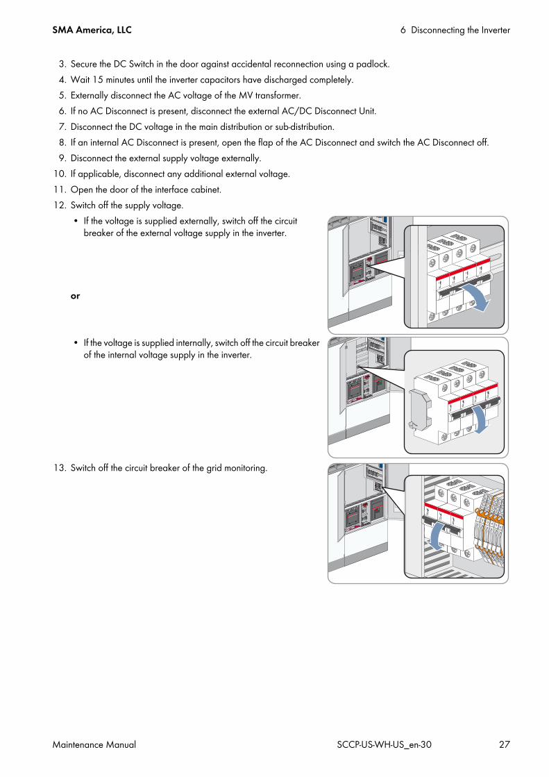
3. Secure the DC Switch in the door against accidental reconnection using a padlock.4. Wait 15 minutes until the inverter capacitors have discharged completely.5. Externally disconnect the AC voltage of the MV transformer.6. If no AC Disconnect is present, disconnect the external AC/DC Disconnect Unit.7. Disconnect the DC voltage in the main distribution or sub-distribution.8. If an internal AC Disconnect is present, open the flap of the AC Disconnect and switch the AC Disconnect off.9. Disconnect the external supply voltage externally.
10. If applicable, disconnect any additional external voltage.11. Open the door of the interface cabinet.12. Switch off the supply voltage.
• If the voltage is supplied externally, switch off the circuit breaker of the external voltage supply in the inverter.
or
• If the voltage is supplied internally, switch off the circuit breaker of the internal voltage supply in the inverter.
13. Switch off the circuit breaker of the grid monitoring.
7 Maintenance in Disconnected State SMA America, LLC
28 SCCP-US-WH-US_en-30 Maintenance Manual
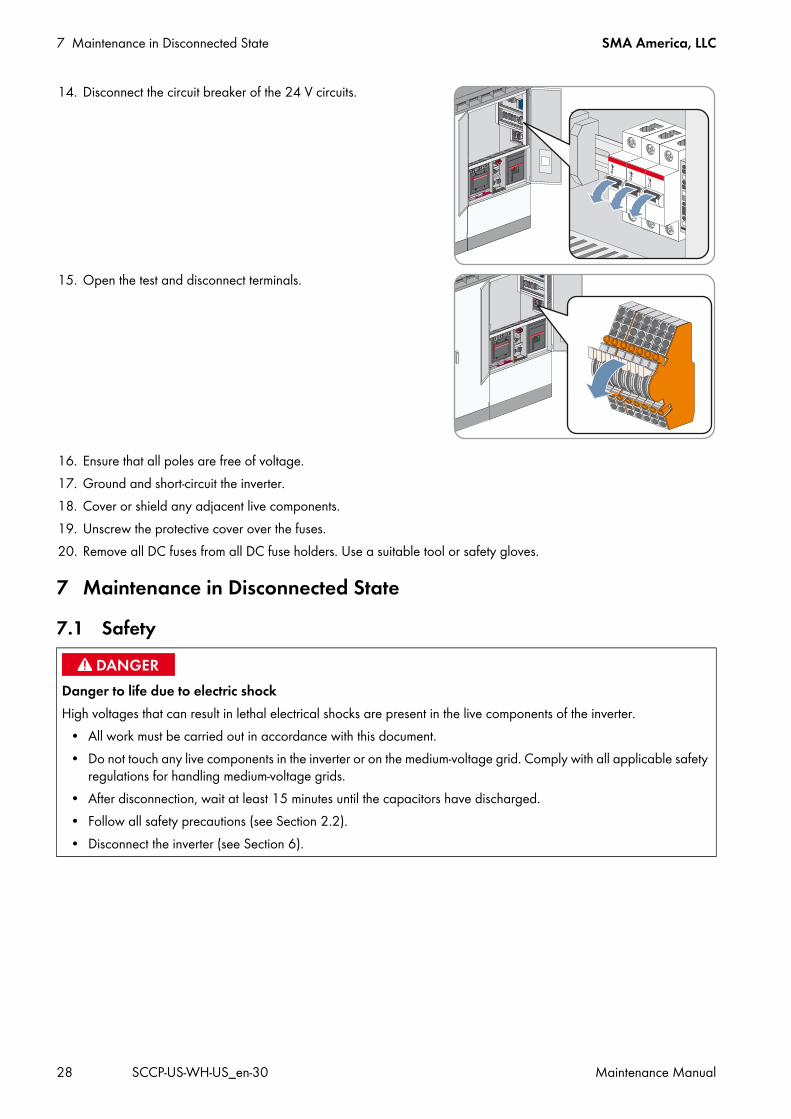
14. Disconnect the circuit breaker of the 24 V circuits.
15. Open the test and disconnect terminals.
16. Ensure that all poles are free of voltage.17. Ground and short-circuit the inverter.18. Cover or shield any adjacent live components.19. Unscrew the protective cover over the fuses.20. Remove all DC fuses from all DC fuse holders. Use a suitable tool or safety gloves.
7 Maintenance in Disconnected State7.1 Safety
Danger to life due to electric shockHigh voltages that can result in lethal electrical shocks are present in the live components of the inverter.
• All work must be carried out in accordance with this document.• Do not touch any live components in the inverter or on the medium-voltage grid. Comply with all applicable safety
regulations for handling medium-voltage grids.• After disconnection, wait at least 15 minutes until the capacitors have discharged.• Follow all safety precautions (see Section 2.2).• Disconnect the inverter (see Section 6).
SMA America, LLC 7 Maintenance in Disconnected State
Maintenance Manual SCCP-US-WH-US_en-30 29
7.2 Removing the Panels
Procedure:
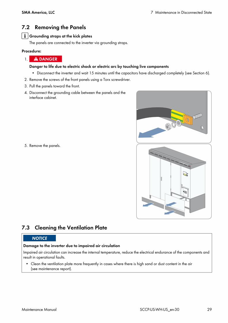
2. Remove the screws of the front panels using a Torx screwdriver.3. Pull the panels toward the front.4. Disconnect the grounding cable between the panels and the
interface cabinet.
5. Remove the panels.
7.3 Cleaning the Ventilation Plate
Grounding straps at the kick platesThe panels are connected to the inverter via grounding straps.
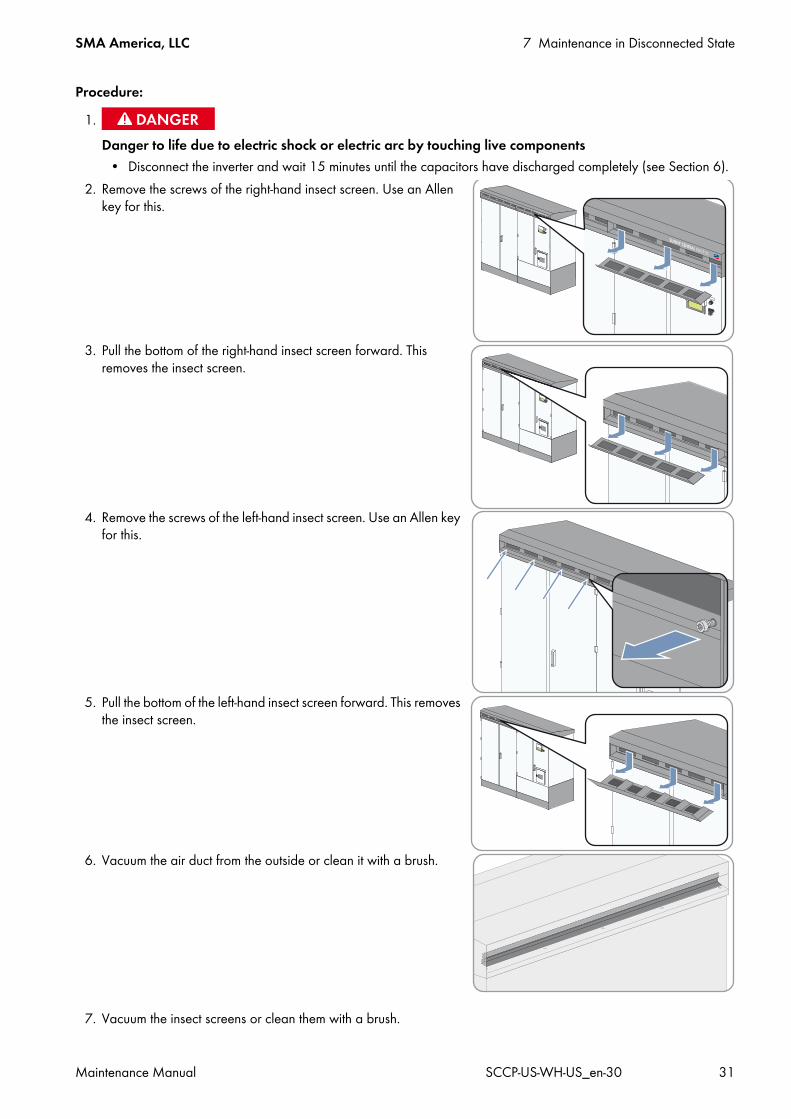
1.Danger to life due to electric shock or electric arc by touching live components
• Disconnect the inverter and wait 15 minutes until the capacitors have discharged completely (see Section 6).
Damage to the inverter due to impaired air circulationImpaired air circulation can increase the internal temperature, reduce the electrical endurance of the components and result in operational faults.
• Clean the ventilation plate more frequently in cases where there is high sand or dust content in the air (see maintenance report).
7 Maintenance in Disconnected State SMA America, LLC
30 SCCP-US-WH-US_en-30 Maintenance Manual
Procedure:
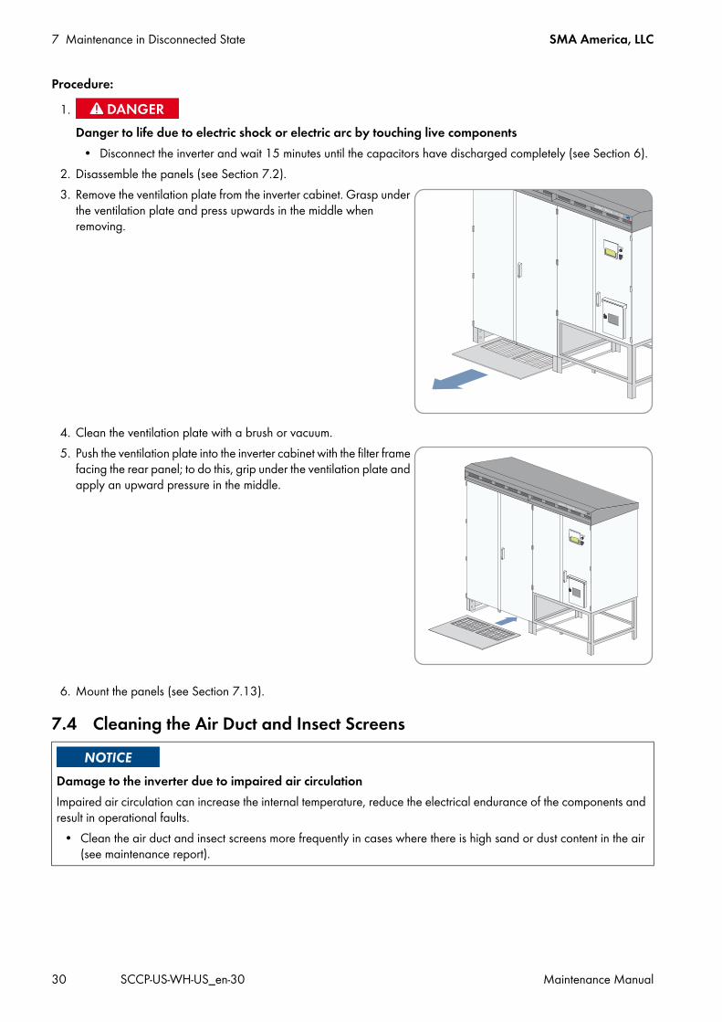
2. Disassemble the panels (see Section 7.2).3. Remove the ventilation plate from the inverter cabinet. Grasp under
the ventilation plate and press upwards in the middle when removing.
4. Clean the ventilation plate with a brush or vacuum.5. Push the ventilation plate into the inverter cabinet with the filter frame
facing the rear panel; to do this, grip under the ventilation plate and apply an upward pressure in the middle.
6. Mount the panels (see Section 7.13).
7.4 Cleaning the Air Duct and Insect Screens
1.Danger to life due to electric shock or electric arc by touching live components
• Disconnect the inverter and wait 15 minutes until the capacitors have discharged completely (see Section 6).
Damage to the inverter due to impaired air circulationImpaired air circulation can increase the internal temperature, reduce the electrical endurance of the components and result in operational faults.
• Clean the air duct and insect screens more frequently in cases where there is high sand or dust content in the air (see maintenance report).
SMA America, LLC 7 Maintenance in Disconnected State
Maintenance Manual SCCP-US-WH-US_en-30 31
Procedure:
2. Remove the screws of the right-hand insect screen. Use an Allen key for this.
3. Pull the bottom of the right-hand insect screen forward. This removes the insect screen.
4. Remove the screws of the left-hand insect screen. Use an Allen key for this.
5. Pull the bottom of the left-hand insect screen forward. This removes the insect screen.
6. Vacuum the air duct from the outside or clean it with a brush.
7. Vacuum the insect screens or clean them with a brush.
1.Danger to life due to electric shock or electric arc by touching live components
• Disconnect the inverter and wait 15 minutes until the capacitors have discharged completely (see Section 6).
7 Maintenance in Disconnected State SMA America, LLC
32 SCCP-US-WH-US_en-30 Maintenance Manual
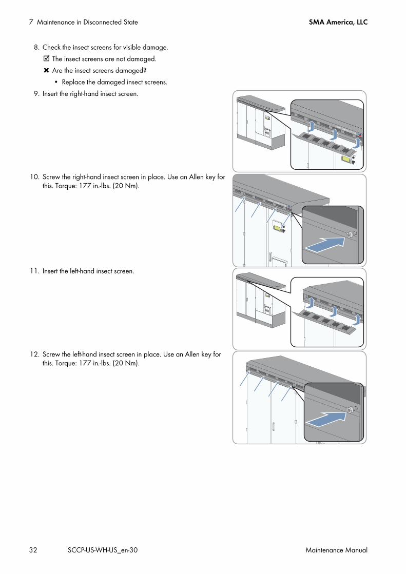
8. Check the insect screens for visible damage. The insect screens are not damaged. Are the insect screens damaged?
• Replace the damaged insect screens.9. Insert the right-hand insect screen.
10. Screw the right-hand insect screen in place. Use an Allen key for this. Torque: 177 in.-lbs. (20 Nm).
11. Insert the left-hand insect screen.
12. Screw the left-hand insect screen in place. Use an Allen key for this. Torque: 177 in.-lbs. (20 Nm).
SMA America, LLC 7 Maintenance in Disconnected State
Maintenance Manual SCCP-US-WH-US_en-30 33
7.5 Cleaning the Interior
2. Open the inverter.3. Ensure that the switch cabinet is sealed.4. Remove dirt and dust from the interior of the switch cabinet and from all assemblies (e.g. DC load-break switch and
AC circuit breaker).5. Remove moisture.6. Check for leaks. If leaks are present, fix the leaks.7. Close the inverter.
7.6 Checking the Fuses
Procedure:
2. Open the interface cabinet.3. Check whether screw connections are loose.
If screw connections are loose, tighten them with the prescribed torque. Torque specifications are shown in the circuit diagram of the inverter. Contact the SMA Service Line if specifications are missing.
4. Check the fuses or tension springs for discoloration and signs of wear.If the fuses or tension springs are discolored or show signs of wear, replace them.
5. Check the insulation and terminals for discoloration and signs of wear.If the insulation or terminals are discolored or show signs of wear, contact the SMA Service Line.
6. Close the interface cabinet.
1.Danger to life due to electric shock or electric arc by touching live components
• Disconnect the inverter and wait 15 minutes until the capacitors have discharged completely (see Section 6).
Damage to screw connections from over-tightening• Only tighten loose connections applying the prescribed torque. Torque specifications are shown in the circuit
diagram of the inverter. Contact the SMA Service Line if specifications are missing.
1.Danger to life due to electric shock or electric arc by touching live components
• Disconnect the inverter and wait 15 minutes until the capacitors have discharged completely (see Section 6).
7 Maintenance in Disconnected State SMA America, LLC
34 SCCP-US-WH-US_en-30 Maintenance Manual
7.7 Checking the Surge Arrester
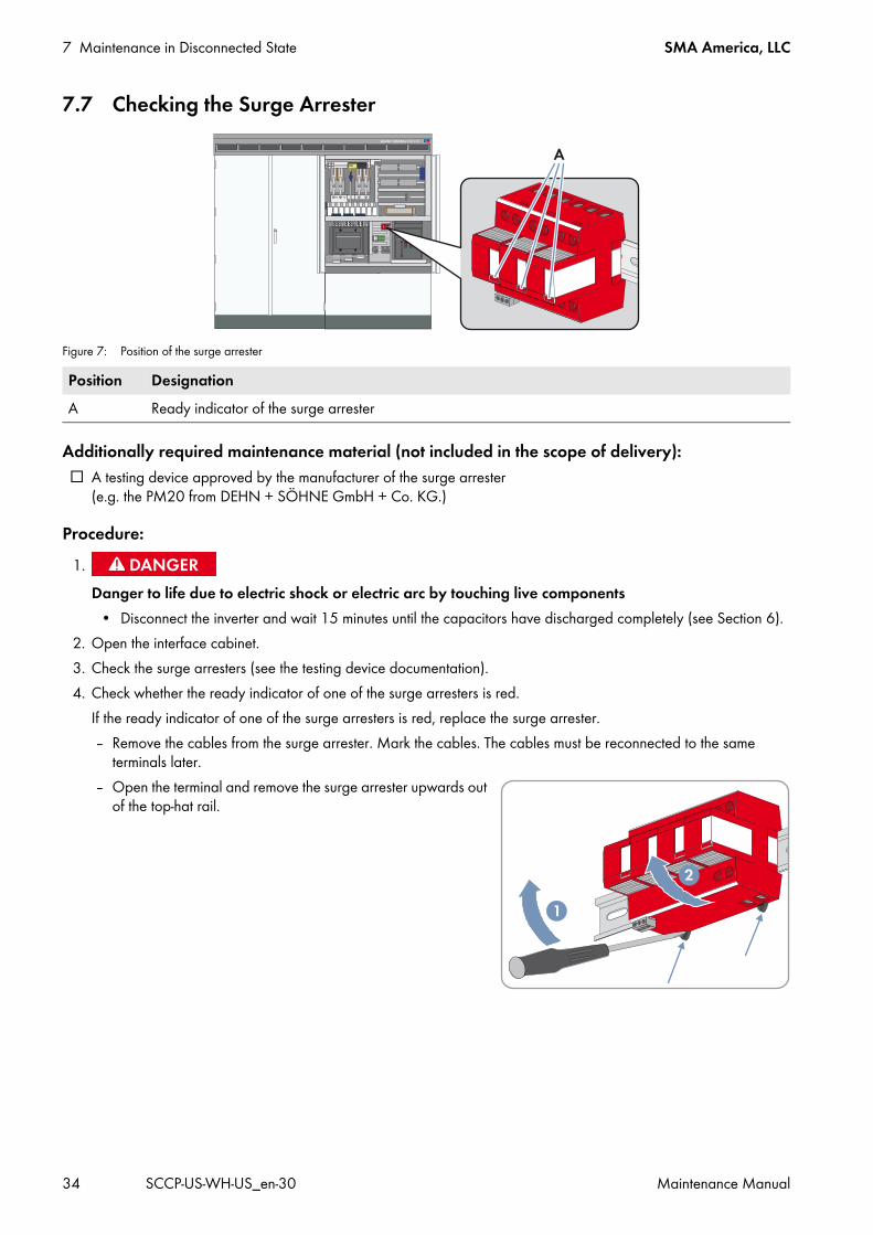
Figure 7: Position of the surge arrester
Additionally required maintenance material (not included in the scope of delivery): A testing device approved by the manufacturer of the surge arrester
(e.g. the PM20 from DEHN + SÖHNE GmbH + Co. KG.)
Procedure:
2. Open the interface cabinet.3. Check the surge arresters (see the testing device documentation).4. Check whether the ready indicator of one of the surge arresters is red.
If the ready indicator of one of the surge arresters is red, replace the surge arrester. – Remove the cables from the surge arrester. Mark the cables. The cables must be reconnected to the same
terminals later. – Open the terminal and remove the surge arrester upwards out
of the top-hat rail.
Position DesignationA Ready indicator of the surge arrester
1.Danger to life due to electric shock or electric arc by touching live components
• Disconnect the inverter and wait 15 minutes until the capacitors have discharged completely (see Section 6).
SMA America, LLC 7 Maintenance in Disconnected State
Maintenance Manual SCCP-US-WH-US_en-30 35
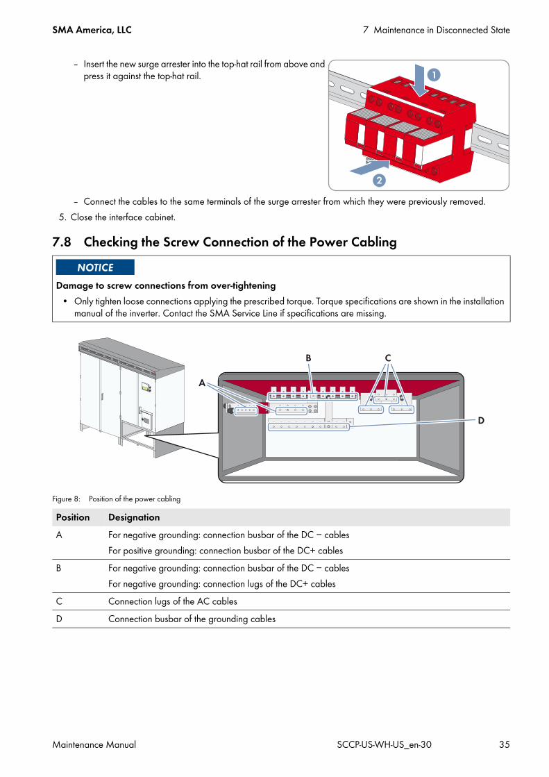
– Insert the new surge arrester into the top-hat rail from above and press it against the top-hat rail.
– Connect the cables to the same terminals of the surge arrester from which they were previously removed.5. Close the interface cabinet.
7.8 Checking the Screw Connection of the Power Cabling
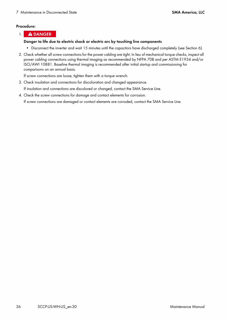
Figure 8: Position of the power cabling
Damage to screw connections from over-tightening• Only tighten loose connections applying the prescribed torque. Torque specifications are shown in the installation
manual of the inverter. Contact the SMA Service Line if specifications are missing.
Position DesignationA For negative grounding: connection busbar of the DC − cables
For positive grounding: connection busbar of the DC+ cablesB For negative grounding: connection busbar of the DC − cables
For negative grounding: connection lugs of the DC+ cablesC Connection lugs of the AC cablesD Connection busbar of the grounding cables
7 Maintenance in Disconnected State SMA America, LLC
36 SCCP-US-WH-US_en-30 Maintenance Manual
Procedure:
2. Check whether all screw connections for the power cabling are tight. In lieu of mechanical torque checks, inspect all power cabling connections using thermal imaging as recommended by NFPA 70B and per ASTM E1934 and/or ISO/AWI 10881. Baseline thermal imaging is recommended after initial startup and commissioning for comparisons on an annual basis. If screw connections are loose, tighten them with a torque wrench.
3. Check insulation and connections for discoloration and changed appearance. If insulation and connections are discolored or changed, contact the SMA Service Line.
4. Check the screw connections for damage and contact elements for corrosion.If screw connections are damaged or contact elements are corroded, contact the SMA Service Line.
1.Danger to life due to electric shock or electric arc by touching live components
• Disconnect the inverter and wait 15 minutes until the capacitors have discharged completely (see Section 6).
SMA America, LLC 7 Maintenance in Disconnected State
Maintenance Manual SCCP-US-WH-US_en-30 37
7.9 Checking the Safety Labels7.9.1 Inverter without Integrated DC Switch
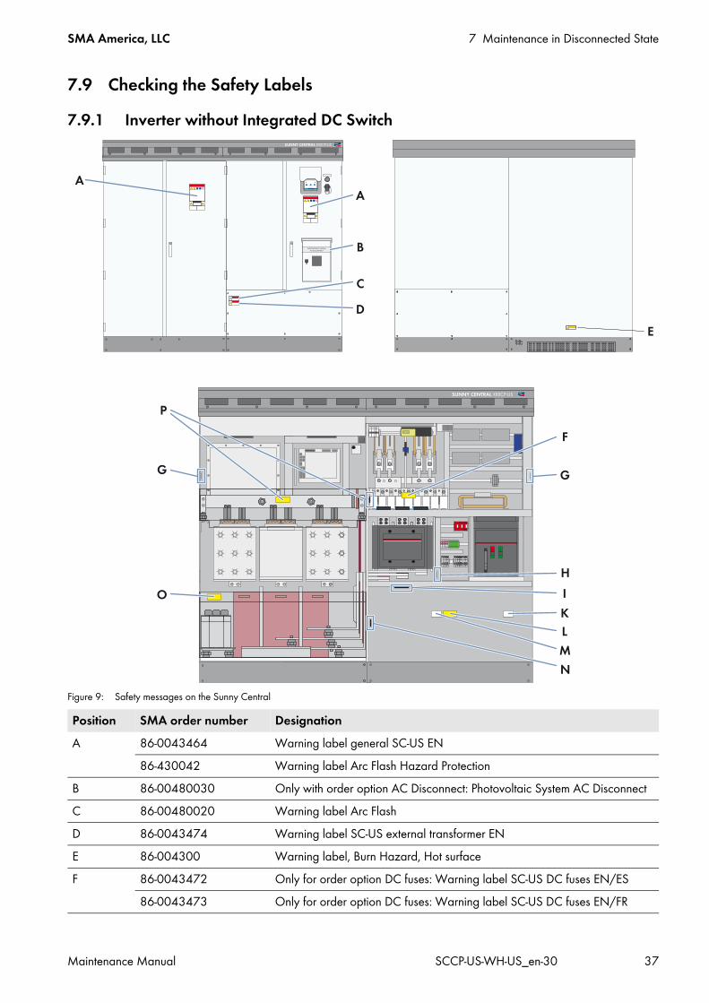
Figure 9: Safety messages on the Sunny Central
Position SMA order number DesignationA 86-0043464 Warning label general SC-US EN
86-430042 Warning label Arc Flash Hazard ProtectionB 86-00480030 Only with order option AC Disconnect: Photovoltaic System AC DisconnectC 86-00480020 Warning label Arc FlashD 86-0043474 Warning label SC-US external transformer ENE 86-004300 Warning label, Burn Hazard, Hot surfaceF 86-0043472 Only for order option DC fuses: Warning label SC-US DC fuses EN/ES
86-0043473 Only for order option DC fuses: Warning label SC-US DC fuses EN/FR
7 Maintenance in Disconnected State SMA America, LLC
38 SCCP-US-WH-US_en-30 Maintenance Manual
G ‒ Type labelH ‒ Label control supply voltageI 86-10867027 For positive grounding: 1,000 V PV‒
86-430045 For positive grounding: 600 V PV‒*86-10867028 For negative grounding: 1,000 V PV+86-430044 For negative grounding: 600 V PV+*
K 86-0043462 ABC 60 Hz86-101300.1 ABC 50 Hz
L 86-0043470 Warning label SC-US Conductors, EN-FR86-0043469 Warning label SC-US Conductors, EN-ES
M 86-0043460 Grounding Electrode TerminalN 86-10867027 For negative grounding or insulated: 1,000 V PV‒
86-430045 For negative grounding or insulated: 600 V PV‒*86-10867028 For positive grounding or insulated: 1,000 V PV+86-430044 For positive grounding or insulated: 600 V PV+*
O 86-108680046 Warning label SC US capacitors C1-C3, C6 optional EN/FR86-108680047 Warning label SC US capacitors C1-C3, C6 optional EN/ES
P 86-0043476 Warning label, SC US stack capacitors EN/ES86-0043477 Warning label, SC US stack capacitors EN/FR
* For Sunny Central 500CP-US 600V
Replacing safety messages• Replace missing or damaged safety labels. These can be ordered from SMA using the SMA order number
stated above.
Position SMA order number Designation
SMA America, LLC 7 Maintenance in Disconnected State
Maintenance Manual SCCP-US-WH-US_en-30 39
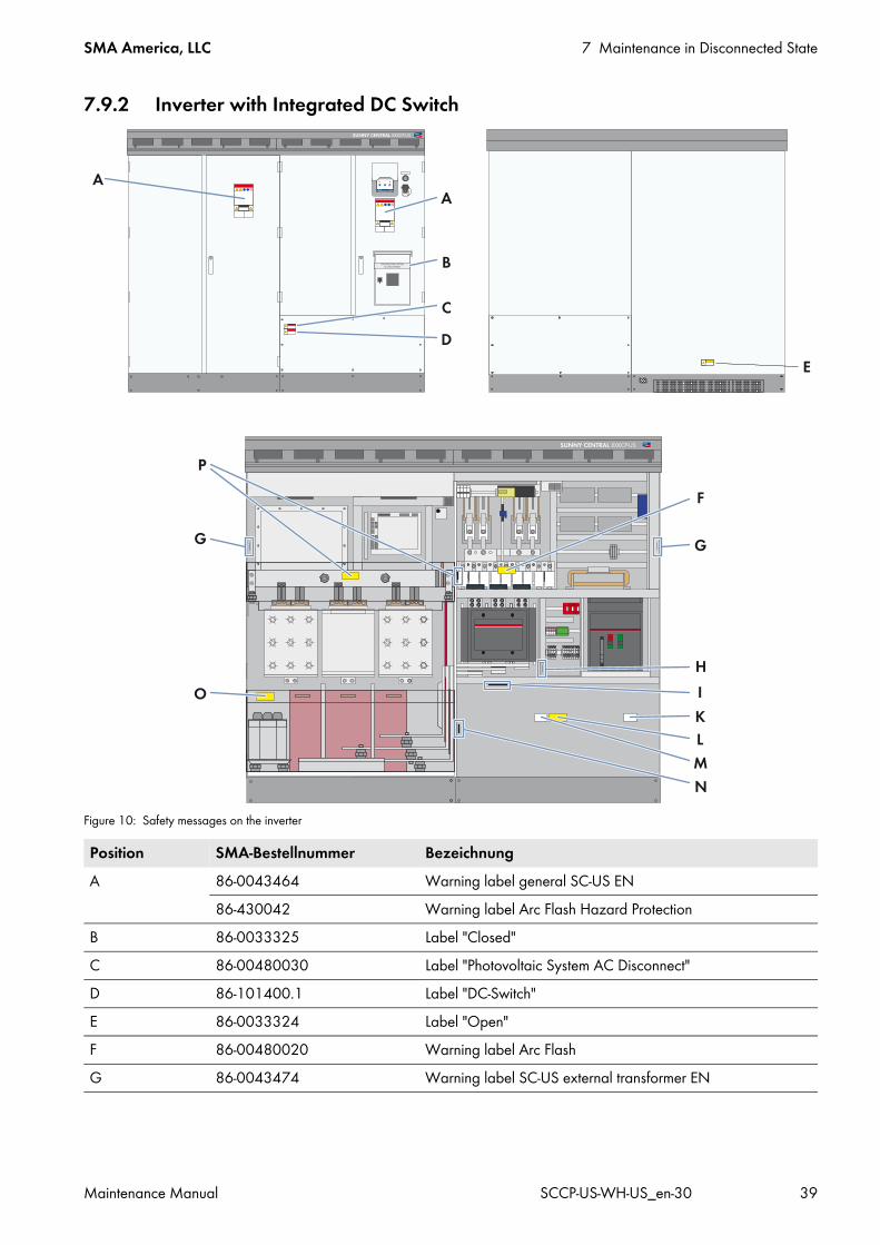
7.9.2 Inverter with Integrated DC Switch
Figure 10: Safety messages on the inverter
Position SMA-Bestellnummer BezeichnungA 86-0043464 Warning label general SC-US EN
86-430042 Warning label Arc Flash Hazard ProtectionB 86-0033325 Label "Closed"C 86-00480030 Label "Photovoltaic System AC Disconnect"D 86-101400.1 Label "DC-Switch"E 86-0033324 Label "Open"F 86-00480020 Warning label Arc FlashG 86-0043474 Warning label SC-US external transformer EN
7 Maintenance in Disconnected State SMA America, LLC
40 SCCP-US-WH-US_en-30 Maintenance Manual
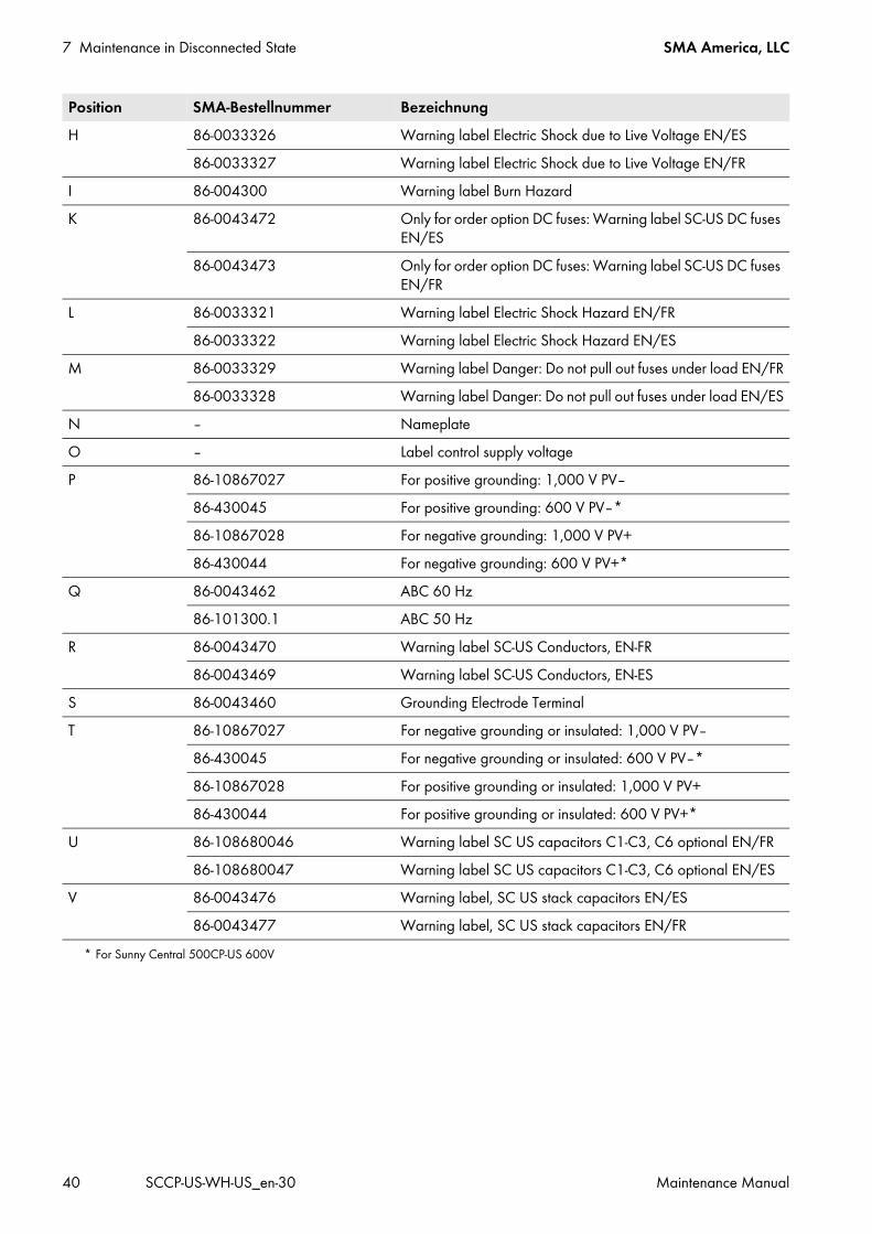
H 86-0033326 Warning label Electric Shock due to Live Voltage EN/ES86-0033327 Warning label Electric Shock due to Live Voltage EN/FR
I 86-004300 Warning label Burn HazardK 86-0043472 Only for order option DC fuses: Warning label SC-US DC fuses
EN/ES86-0043473 Only for order option DC fuses: Warning label SC-US DC fuses
EN/FRL 86-0033321 Warning label Electric Shock Hazard EN/FR
86-0033322 Warning label Electric Shock Hazard EN/ESM 86-0033329 Warning label Danger: Do not pull out fuses under load EN/FR
86-0033328 Warning label Danger: Do not pull out fuses under load EN/ESN ‒ NameplateO ‒ Label control supply voltageP 86-10867027 For positive grounding: 1,000 V PV‒
86-430045 For positive grounding: 600 V PV‒*86-10867028 For negative grounding: 1,000 V PV+86-430044 For negative grounding: 600 V PV+*
Q 86-0043462 ABC 60 Hz86-101300.1 ABC 50 Hz
R 86-0043470 Warning label SC-US Conductors, EN-FR86-0043469 Warning label SC-US Conductors, EN-ES
S 86-0043460 Grounding Electrode TerminalT 86-10867027 For negative grounding or insulated: 1,000 V PV‒
86-430045 For negative grounding or insulated: 600 V PV‒*86-10867028 For positive grounding or insulated: 1,000 V PV+86-430044 For positive grounding or insulated: 600 V PV+*
U 86-108680046 Warning label SC US capacitors C1-C3, C6 optional EN/FR86-108680047 Warning label SC US capacitors C1-C3, C6 optional EN/ES
V 86-0043476 Warning label, SC US stack capacitors EN/ES86-0043477 Warning label, SC US stack capacitors EN/FR
* For Sunny Central 500CP-US 600V
Position SMA-Bestellnummer Bezeichnung
SMA America, LLC 7 Maintenance in Disconnected State
Maintenance Manual SCCP-US-WH-US_en-30 41
Procedure:
2. Open all inverter doors.3. Check whether any label is damaged or missing.
Replace the safety labels if they are damaged or missing. In the case of missing or damaged safety labels, contact the SMA Service Line.
4. Close the inverter.
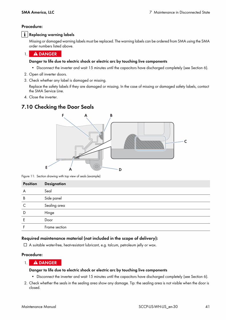
7.10 Checking the Door Seals
Figure 11: Section drawing with top view of seals (example)
Required maintenance material (not included in the scope of delivery): A suitable water-free, heat-resistant lubricant, e.g. talcum, petroleum jelly or wax.
Procedure:
2. Check whether the seals in the sealing area show any damage. Tip: the sealing area is not visible when the door is closed.
Replacing warning labelsMissing or damaged warning labels must be replaced. The warning labels can be ordered from SMA using the SMA order numbers listed above.
1.Danger to life due to electric shock or electric arc by touching live components
• Disconnect the inverter and wait 15 minutes until the capacitors have discharged completely (see Section 6).
Position DesignationA SealB Side panelC Sealing areaD HingeE DoorF Frame section
1.Danger to life due to electric shock or electric arc by touching live components
• Disconnect the inverter and wait 15 minutes until the capacitors have discharged completely (see Section 6).

7 Maintenance in Disconnected State SMA America, LLC
42 SCCP-US-WH-US_en-30 Maintenance Manual
If seals are damaged, contact the SMA Service Line.3. Maintain seals with talcum, petroleum jelly or wax. This prevents frost damage.4. If the side panels are removed, check whether or not the seals in the side panels show any damage in the sealing area.
If seals are damaged, contact the SMA Service Line.
7.11 Checking the Latches, Door Stops and HingesRequired maintenance material (not included in the scope of delivery): A suitable water-free, heat-resistant lubricant, e.g. WD40. Non-greasing antifreeze, e.g. PS88.
Procedure:
2. Check whether the doors latch easily. Open and close the doors several times.If the doors do not latch easily, lubricate all moving parts of the latch.
3. Check whether the doors can be held in place.If the doors cannot be held in place, lubricate the door stops.
4. Check whether the door hinges move easily.If the door hinges do not move easily, lubricate them.
5. Lubricate all moving parts and movement points.6. If the inverter is installed in regions where below-freezing temperatures occur, apply the non-greasing antifreeze to
the profile cylinder of the door locks and the key switch in order to protect against freezing.
7.12 Checking the Switch Cabinet for CorrosionRequired maintenance material (not included in the scope of delivery): Touch-up sticks, paint brushes, cans of spray paint or, alternatively, 2K-PUR acrylic paint in the proper RAL color can
be used to remove small-area surface damage. Observe the relevant instructions of the paint manufacturer. Touch-up paint or 2K-PUR acrylic paint in the proper RAL color can be used to repair large-area surface damage.
Observe the relevant instructions of the paint manufacturer.
Abrasive cloth Degreaser
Procedure:
1.Danger to life due to electric shock or electric arc by touching live components
• Disconnect the inverter and wait 15 minutes until the capacitors have discharged completely (see Section 6).
Position RAL color Article numberRoof RAL 7004 87-5051311Base RAL 7004 87-5051312Enclosure RAL 9016 87-5051310
1.Danger to life due to electric shock or electric arc by touching live components
• Disconnect the inverter and wait 15 minutes until the capacitors have discharged completely (see Section 6).
SMA America, LLC 7 Maintenance in Disconnected State
Maintenance Manual SCCP-US-WH-US_en-30 43
2. Check surfaces for damage or corrosion.If the surfaces are damaged, repair them without delay or within three weeks at the latest.If the surfaces are corroded, repair them without delay or within three weeks at the latest.
3. Remove dirt.4. To remove small-area surface damage:
• Sand the affected area.• Clean the affected area with a degreaser.• Paint the affected area.
5. To remove large-area surface damage:• Sand the entire surface.• Clean the entire surface with a degreaser.• Paint the entire surface.
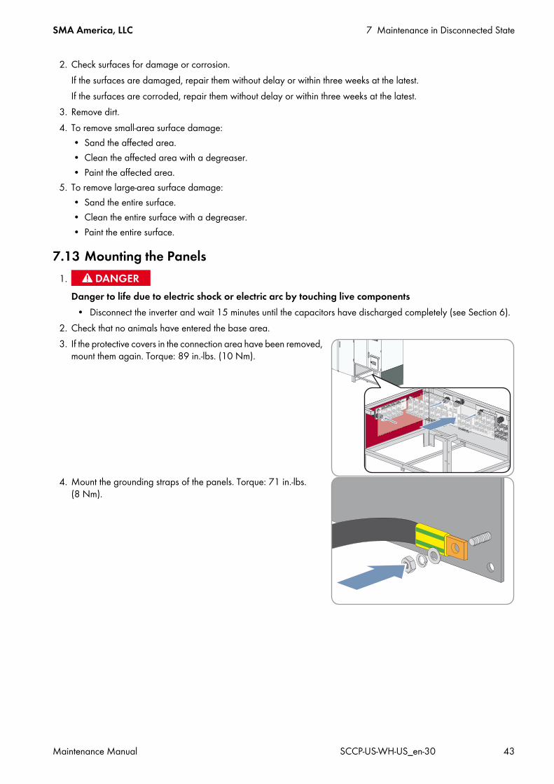
7.13 Mounting the Panels
2. Check that no animals have entered the base area.3. If the protective covers in the connection area have been removed,
mount them again. Torque: 89 in.-lbs. (10 Nm).
4. Mount the grounding straps of the panels. Torque: 71 in.-lbs. (8 Nm).
1.Danger to life due to electric shock or electric arc by touching live components
• Disconnect the inverter and wait 15 minutes until the capacitors have discharged completely (see Section 6).
8 Connecting the Control Voltage SMA America, LLC
44 SCCP-US-WH-US_en-30 Maintenance Manual
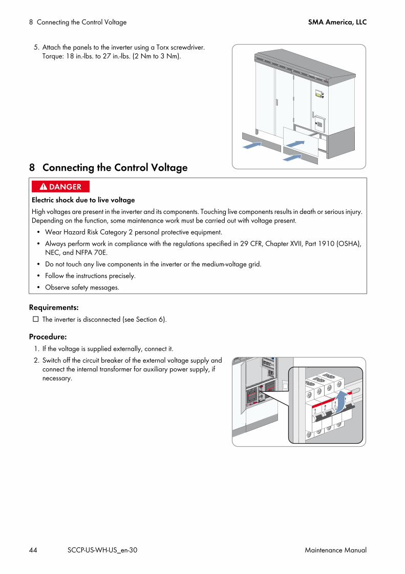
5. Attach the panels to the inverter using a Torx screwdriver. Torque: 18 in.-lbs. to 27 in.-lbs. (2 Nm to 3 Nm).
8 Connecting the Control Voltage
Requirements: The inverter is disconnected (see Section 6).
Procedure:1. If the voltage is supplied externally, connect it.2. Switch off the circuit breaker of the external voltage supply and
connect the internal transformer for auxiliary power supply, if necessary.
Electric shock due to live voltage High voltages are present in the inverter and its components. Touching live components results in death or serious injury. Depending on the function, some maintenance work must be carried out with voltage present.
• Wear Hazard Risk Category 2 personal protective equipment.• Always perform work in compliance with the regulations specified in 29 CFR, Chapter XVII, Part 1910 (OSHA),
NEC, and NFPA 70E. • Do not touch any live components in the inverter or the medium-voltage grid.• Follow the instructions precisely.• Observe safety messages.
SMA America, LLC 9 Maintenance when Control Voltage is Present
Maintenance Manual SCCP-US-WH-US_en-30 45
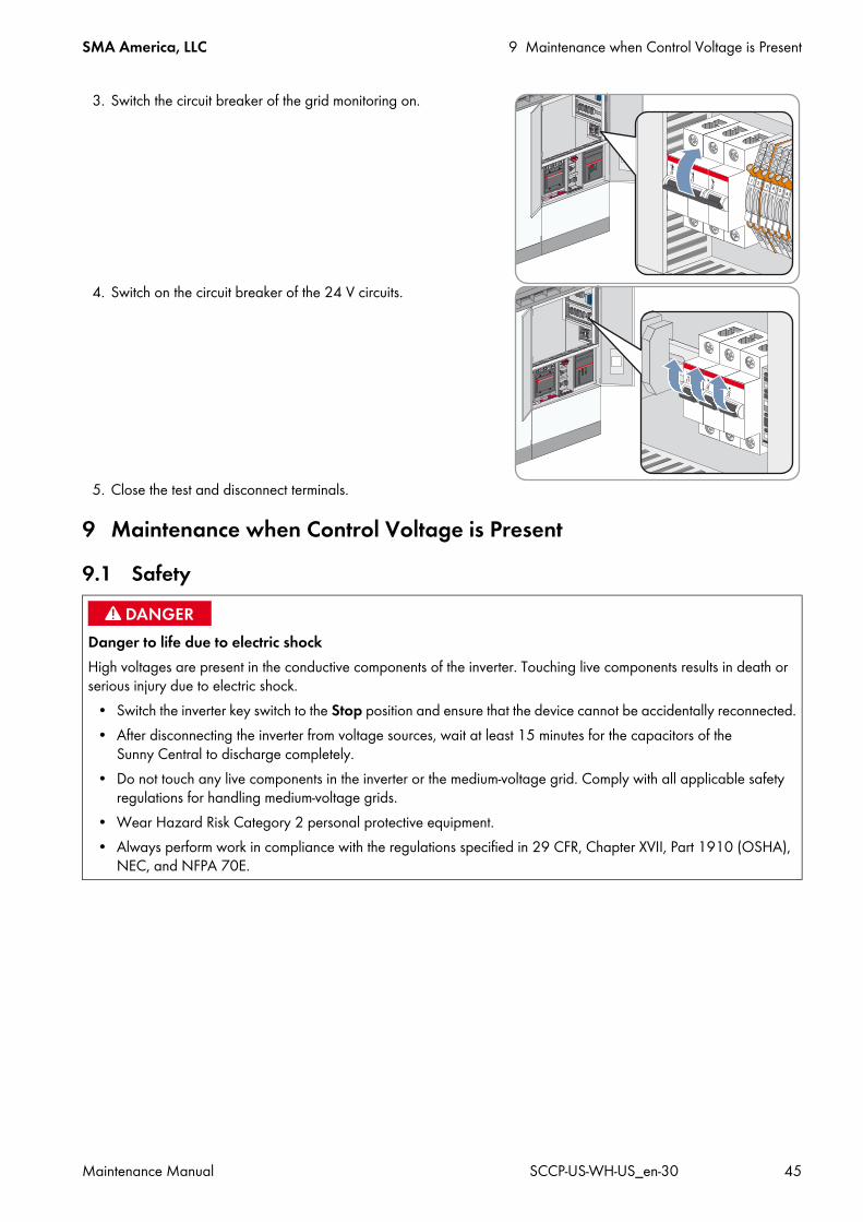
3. Switch the circuit breaker of the grid monitoring on.
4. Switch on the circuit breaker of the 24 V circuits.
5. Close the test and disconnect terminals.
9 Maintenance when Control Voltage is Present9.1 Safety
Danger to life due to electric shockHigh voltages are present in the conductive components of the inverter. Touching live components results in death or serious injury due to electric shock.
• Switch the inverter key switch to the Stop position and ensure that the device cannot be accidentally reconnected.• After disconnecting the inverter from voltage sources, wait at least 15 minutes for the capacitors of the
Sunny Central to discharge completely.• Do not touch any live components in the inverter or the medium-voltage grid. Comply with all applicable safety
regulations for handling medium-voltage grids.• Wear Hazard Risk Category 2 personal protective equipment.• Always perform work in compliance with the regulations specified in 29 CFR, Chapter XVII, Part 1910 (OSHA),
NEC, and NFPA 70E.
9 Maintenance when Control Voltage is Present SMA America, LLC
46 SCCP-US-WH-US_en-30 Maintenance Manual
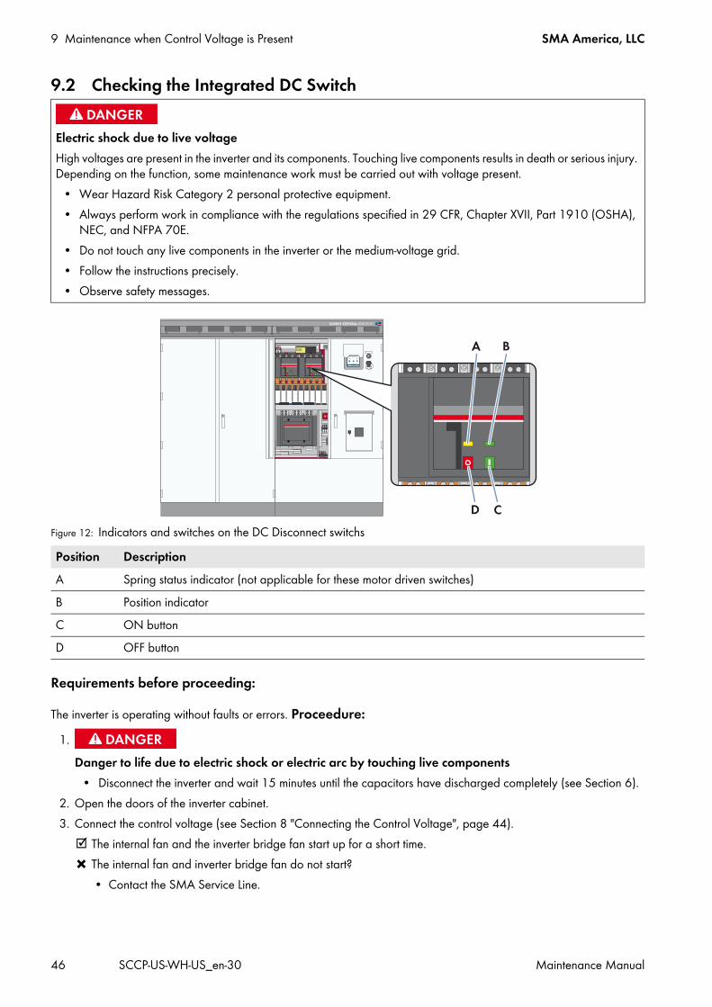
9.2 Checking the Integrated DC Switch
Figure 12: Indicators and switches on the DC Disconnect switchs
Requirements before proceeding:
The inverter is operating without faults or errors. Proceedure:
2. Open the doors of the inverter cabinet.3. Connect the control voltage (see Section 8 "Connecting the Control Voltage", page 44).
The internal fan and the inverter bridge fan start up for a short time. The internal fan and inverter bridge fan do not start?
• Contact the SMA Service Line.
Electric shock due to live voltage High voltages are present in the inverter and its components. Touching live components results in death or serious injury. Depending on the function, some maintenance work must be carried out with voltage present.
• Wear Hazard Risk Category 2 personal protective equipment.• Always perform work in compliance with the regulations specified in 29 CFR, Chapter XVII, Part 1910 (OSHA),
NEC, and NFPA 70E. • Do not touch any live components in the inverter or the medium-voltage grid.• Follow the instructions precisely.• Observe safety messages.
Position DescriptionA Spring status indicator (not applicable for these motor driven switches)B Position indicatorC ON buttonD OFF button
1.Danger to life due to electric shock or electric arc by touching live components
• Disconnect the inverter and wait 15 minutes until the capacitors have discharged completely (see Section 6).
SMA America, LLC 9 Maintenance when Control Voltage is Present
Maintenance Manual SCCP-US-WH-US_en-30 47
Context:The Integrated DC Switch option consists of a control actuator switch on the inverter door, red and green indictor lights on the inverter door, and two motor driven DC load-break switches inside the inverter. This proceedure tests the correct operation of each of these components.
Proceedure: 1. Verify that the Integrated DC Switch control actuator switch on the inverter door is in the ON position, and that the
green CLOSED indicator light is illuminated.2. Switch the key switch of the inverter to Stop.3. Check whether the red OPEN indicator light on the inverter door is illuminated, indicating that the DC load-break
switches are open.4. Open the doors of the interface cabinet.5. Check whether the DC load-break switches are both indicating the Off position. If either of the DC load-break
switches are not indicating the Off position, contact the SMA Service Line. 6. Close the doors of the interface cabinet.7. Switch the key switch of the inverter to Start.8. Check whether the green CLOSED indicator is illuminated, indicating that the DC load-break switches are closed.9. Open the doors of the interface cabinet.
10. Check whether the DC load-break switches are indicating the On position. If the DC load-break switches are not both indicating the On position, contact the SMA Service Line.
11. Switch the Integrated DC Switch control actuator switch on the inverter door to OFF.12. Check whether the DC load-break switches are both indicating the Off position. If either of the DC load-break
switches are not indicating the Off position, contact the SMA Service Line.13. Check whether the red OPEN indicator light on the inverter door is illuminated, indicating that the DC load-break
switches are open.14. Test the switching process three times. Check each time whether the DC load-break switches have switched.15. Close the doors of the interface cabinet.
9 Maintenance when Control Voltage is Present SMA America, LLC
48 SCCP-US-WH-US_en-30 Maintenance Manual
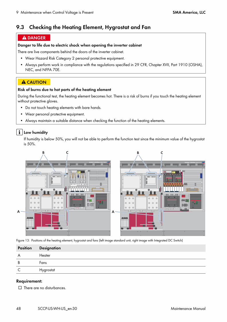
9.3 Checking the Heating Element, Hygrostat and Fan
Figure 13: Positions of the heating element, hygrostat and fans (left image standard unit, right image with Integrated DC Switch)
Requirement: There are no disturbances.
Danger to life due to electric shock when opening the inverter cabinetThere are live components behind the doors of the inverter cabinet.
• Wear Hazard Risk Category 2 personal protective equipment.• Always perform work in compliance with the regulations specified in 29 CFR, Chapter XVII, Part 1910 (OSHA),
NEC, and NFPA 70E.
Risk of burns due to hot parts of the heating elementDuring the functional test, the heating element becomes hot. There is a risk of burns if you touch the heating element without protective gloves.
• Do not touch heating elements with bare hands.• Wear personal protective equipment.• Always maintain a suitable distance when checking the function of the heating elements.
Low humidityIf humidity is below 50%, you will not be able to perform the function test since the minimum value of the hygrostat is 50%.
Position DesignationA HeaterB FansC Hygrostat

SMA America, LLC 9 Maintenance when Control Voltage is Present
Maintenance Manual SCCP-US-WH-US_en-30 49
Procedure:
2. Open the doors of the inverter cabinet.3. Connect the control voltage (see Section 8).
The internal fan and the fan of the inverter bridge start up for a short time. The internal fan and fan of the inverter bridge do not start?
• Contact the SMA Service Line.4. Set the hygrostat to the minimum value. To do so, pull out the selector switch gently. Tip: the hygrostat is adjusted
correctly if the relay of the hygrostat emits an audible click. 5. Check whether the heating element is beginning to radiate heat after approx. five minutes. If the heating element
does not radiate heat, contact the SMA Service Line.6. Reset the hygrostat to the initial value. Press the selector switch against the hygrostat again. The initial value of the
hygrostat is included in the circuit diagram. In addition, there is a white marking on the selector switch.7. Close the inverter doors.
1.Danger to life due to electric shock or electric arc by touching live components
• Disconnect the inverter and wait 15 minutes until the capacitors have discharged completely (see Section 6).
10 Contact SMA America, LLC
50 SCCP-US-WH-US_en-30 Maintenance Manual
10 ContactIf you have technical problems concerning our products, contact the SMA Service Line. We require the following information in order to provide you with the necessary assistance:
• Device type• Serial number• Type and number of modules connected• Communication type• Error number and error message
United States/Estados Unidos
SMA America, LLCRocklin, CA
+1 877-MY-SMATech (+1 877-697-6283)*+1 916 625-0870**
* toll free for USA, Canada and Puerto Rico / Llamada gratuita en EE. UU., Canadá y Puerto Rico** international / internacional
Canada/Canadá
SMA Canada, Inc.Toronto
+1 877-MY-SMATech (+1 877-697-6283)***
*** toll free for Canada / gratuit pour le Canada
SMA America, LLC 11 Revision History
Maintenance Manual SCCP-US-WH-US_en-30 51
11 Revision HistoryIn this section, you will find an overview of the content changes in the new version of this document. The pages where changes were made are indicated behind the version.
Revisions to version 3.0New danger
Q at Night 13, 26New feature
Integrated DC Switch 10, 16, 20, 21, 26, 39, 46New label
"Closed" 39"DC-Switch" 39"Open" 39
New warningGFDI required 10
New warning labelDanger Do not pull out fuses under load 40Electric Shock due to Live Voltage 40Electric Shock Hazard 40
Updated contentHazard Risk Category 2 7, 11, 12, 13, 14, 15, 21, 23, 25, 26, 44, 45, 46, 48Personal protective equipment clothing requirement 15Personal protective equipment glove requirement 15Personal protective equipment specification 15Trademark information 2
Updated dangerTouching live components results in death or serious injury. 44

www.SMA-Solar.comSMA Solar Technology