Embed Size (px)
Citation preview

8/16/2019 A PRACTICAL APPROACH TO THE DESIGN a motor.pdf
http://slidepdf.com/reader/full/a-practical-approach-to-the-design-a-motorpdf 1/6
Dr. Virajit A. Gundale,Mangesh S. Kulkarni / International Journal of Engineering
Research and Applications (IJERA) ISSN: 2248-9622 www.ijera.com
Vol. 2, Issue 1, Jan-Feb 2012, pp. 299-304
299 | P a g e
A PRACTICAL APPROACH TO THE DESIGN AND
IMPLEMENTATION OF A WATER COOLED SINGLE PHASE
SUBMERSIBLE MOTOR
Dr. Virajit A. Gundale1, Mangesh S. Kulkarni
2
1Professor & Academic-Inchar ge, Sharad Institute of Technology College of Engineering, Yadrav Dist. Kolhapur
India. 2Asisstant Professor, Sharad Institute of Technology College of Engineering, Yadrav Dist. Kolhapur India.
ABSTRACT
A lot of research work has already been done in the
case of Single Phase Induction motors. But
comparatively, very little work has been done on
Submersible motors. Submersible motor
manufacturers find it very difficult to design by
themselves such motors as very little literature is
available on the same. In India, Bureau of Indian
standards gives only an overall configuration about
such motors. It is not providing any design related
data or information. Most of the Indian
manufacturers produce such pumps and motors on
pure trial and error basis. They make their own
winding combination to optimize the performance.
Larger manufacturers design Submersible motors
based on the published procedure for design ofInduction motors by making some necessary
assumptions and changes. For small scale
manufactures this design procedure is not easily
accessible. The Induction motor design calculations
are very lengthy involving huge number of
variables. These results do not work properly in
case of Submersible motors. There is a need to
modify some steps and make some necessary
adjustment which is also not an easy task. This
paper presents a practical and working procedure
to design water cooled single phase submersible
motor which can be easily applicable to rapidly
design such motors from 0.5 hp to 5 hp. The
calculations presented in this paper are based on
available market stampings and do not include its
design. The designs are verified and validated by a
reputed manufacturer and will give its
recommendation.
Keywords -Single Phase Induction motors, pumps,
Submersible motors, Running winding, Auxiliary
winding, Core length
I. INTRODUCTION
There is a huge demand for single phase submersible
motors majorly due to the easily availability of the 1-Φ
Power supply. Such motors are usually coupled with a
single or multi-stage pump which can either be Radial
or Mixed flow type. Single phase submersible motors
are usually 2-pole type. They consist of a Primary or
Main (Running) winding and a Auxiliary (starting)
winding as shown in figure 1.0
Figure 1.0 A Typical Capacitor Start Capacitor Run
Single phase motor
The cooling medium employed in such motors is
usually oil or water. The later very common nowadays
due to maintenance and ease of rewinding. This paper
focuses on the water cooled type operating on 50 Hz.
For such motor the recommended winding wire as per
IS 8783(Part 2) is PVC insulated.
II. Simplified design procedure
i) Number of turns in main winding:
The number of turns in the running winding can be
calculated as below:
Stator induced voltage E= 4.44f ϕmTmK wm
8/16/2019 A PRACTICAL APPROACH TO THE DESIGN a motor.pdf
http://slidepdf.com/reader/full/a-practical-approach-to-the-design-a-motorpdf 2/6
Dr. Virajit A. Gundale,Mangesh S. Kulkarni / International Journal of Engineering
Research and Applications (IJERA) ISSN: 2248-9622 www.ijera.com
Vol. 2, Issue 1, Jan-Feb 2012, pp. 299-304
300 | P a g e
Where Tm = number of turns in the running winding,
K wm= winding factor for the running winding.
Number of turns in the running winding
Tm=E
4.44f ϕm Kwm …(1)
Where, ϕm = fluxpole
ф= flux density x slots per pole x x Wb
The value of stator induced voltage E is approximately
equal to 95 percent of supply voltage V. The winding
factor for the running winding can be assumed
between 0.8 to 0.955 max. Li is the Iron length, Core
length or Stack length. In this simplified procedure a
trial length is used. The calculation is repeated a
number of times till optimum number of main winding
turns per slot are not achieved. Optimum number of
turns can be calculated either by calculation of the area
of one slot, area of the total number of conductors and
multiplying the same by some gap factor.
The more accurate way to assign the
optimum number of turns for a specific stamping or
lamination slot is to consult the motor winder as he is
the true judge to recommend the maximum number of
turns of a particular wire size which the slot can
accommodate.
The number of turns per series pole for the main
(running) winding
T pm=Tm
p …(2)
ii) Running Winding ConductorsCurrent carried by each running winding conductor
Irated=hpx0 .746
Vηcos ϕ …(3)
Where, η is the efficiency and cosϕ is the power
factor. The values of Efficiency and power factor can
be taken from Table 1.0
H.P. Efficiency Power
factor
0.5 0.65 0.62
0.75 0.67 0.63
1.0 0.68 0.64
1.5 0.69 0.64
2.0 0.7 0.7
3.0 0.71 0.8
4.0 0.72 0.83
5.0 0.73 0.85
6.0 0.74 0.9
Table 1.0 Efficiency and power factor for single phase
motors
Area of running winding conductor am =Im
δ
Where δ is the current density in Amps/mm2
Conductor size for the running winding can be
calculated as follows-
Therefore area of running winding conductor
=IRated
δ
Practical procedure for determining current density δ:
By experience, 1.0 mm diameter conductor can carry
maximum 10.25 amp of current ,and area of 1.0diameter conductor is 0.785
Therefore current density δ = or
δ = 10.25
0.785 = 13.0573 Amps/mm2
This value can be used directly.
Diameter size of running winding conductor
d = Am x 4
π
iii) Running winding Capacitor calculation
C=IratedxNo of turns of running windingxPower factor
2 xπx50xVratedxNo of starting winding turns
iv) No of turns in starting winding
Assume K=1.25
=0.8 winding factor for main winding
=0.85 winding factor for auxiliary winding
Ta=kx Tm xK wm
Kwa
Starting winding conductor size calculation:
d = Am x4
Ta xπ
where, Am=Tm xπxdr2
4
v) Starting capacitor selection

8/16/2019 A PRACTICAL APPROACH TO THE DESIGN a motor.pdf
http://slidepdf.com/reader/full/a-practical-approach-to-the-design-a-motorpdf 3/6
Dr. Virajit A. Gundale,Mangesh S. Kulkarni / International Journal of Engineering
Research and Applications (IJERA) ISSN: 2248-9622 www.ijera.com
Vol. 2, Issue 1, Jan-Feb 2012, pp. 299-304
301 | P a g e
Starting capacitor can be selected from a chart which
most of the leading manufactures follow as shown
below in Table 1.1
Table 1.1 Starting Capacitor selection chart
(Courtesy : Sarda Capacitors, Bangalore, INDIA)
III. Design of 1 hp Single phase water cooled
motor using the simplified method:
Input data:Flux density=1.1Wb/m2 ,Trial Core length= 189 mm
(Finalized after a few trials), Teeth slot width=1.7mm
,No of poles=2 ,No of slots=24, Bore size=50mm
1. Flux per pole :
ф= flux density* slots per pole**
=1.1x24x1.7x10−3x189x10−3
2
= 4.241 x10⁻³
Wb Number of turns in Running winding
Tm=
4.44f ϕm Kwm
= 219
4.44∗50∗0.955∗4.241∗10−3
= 243.55
Now,
Rated current I=hpx0.746
V ηcosϕ
=746
230x0.55x0.78
=7.56 Amps
Area of running winding conductor
Am=
=7.56
13.0573
= 0.5789 2
2. Diameter size of running winding conductor :
d=
x4
π
= 0.5789x4
=0.8586 mm Say 0.8 mm
No of conductors per slot = No of Turns
No.of Poles x No.of coils
= 243.55
2 X 4
=30.44 Say 30
By experience, 30 number of turns of 0.8 mm are the
maximum number of turns which this particular slot
can accommodate.
3. Running winding Capacitor calculation :
C=IratedxNo of turns of running windingxPower factor
2 xπx50xVratedxNo of starting winding
=7.56x30x0.78
2xπx50x230x37
=66µF say 61µF (36 + 25 µF)
Starting winding calculations:
No of turns in starting winding,
Assume K=1.25
Kwm =0.8 winding factor for main winding
Kwa =0.85 winding factor for auxiliary winding
Ta=k ∗Tm ∗Kwm
Kwa =
1.25∗30∗0.8
0.85
= 35.3 say 37 (Maximum turns)
4. Starting winding conductor size calculation :
d =
x 4
x
where Am= x x dr2
4
Am=30∗∗0.85862
4
=17.37mm2
d = 17.37 x 4
37 x
S. No H.P. Recommended StartingCapacitor(μF)
1 0.5 80-100
2 0.75 100-120
3 1.0 120-150
4 1.5 120-150
5 2.0 120-150
6 3.0 150-200
7 4.0 200-250
8 5.0 200-250

8/16/2019 A PRACTICAL APPROACH TO THE DESIGN a motor.pdf
http://slidepdf.com/reader/full/a-practical-approach-to-the-design-a-motorpdf 4/6
Dr. Virajit A. Gundale,Mangesh S. Kulkarni / International Journal of Engineering
Research and Applications (IJERA) ISSN: 2248-9622 www.ijera.com
Vol. 2, Issue 1, Jan-Feb 2012, pp. 299-304
302 | P a g e
=0.77 mm say 0.7
5. Starting capacitor selection :
Selecting 120-150 µF as the starting capacitor fromTable 1.1.
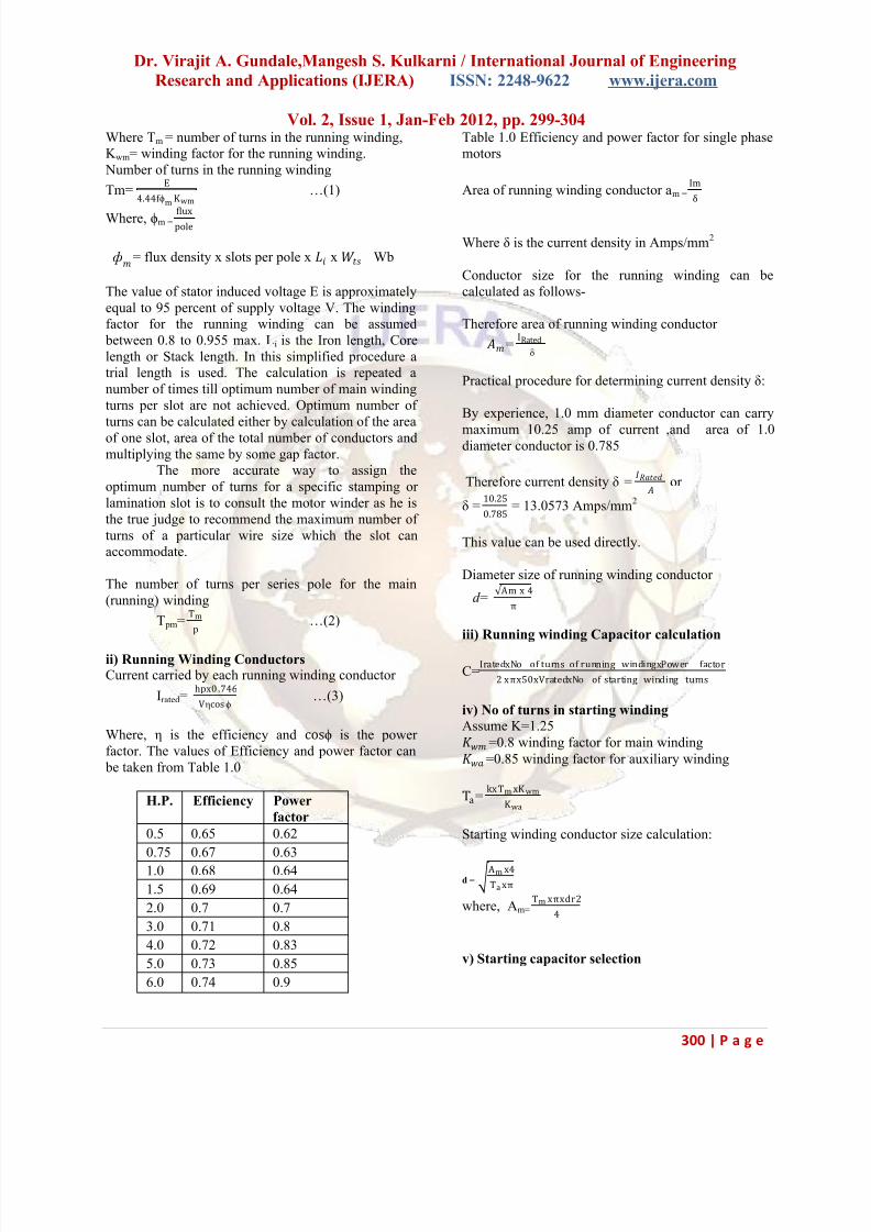
Figure 1.2 show the winding distribution. There will
be 8 coils for the running winding which will
accommodate 16 slots of the stamping where as 2
Coils for starting winding which will accommodate
the remaining 8 Slots.
Figure 1.2 Winding Distributions
III. RESULTS AND DISCUSSIONS
The results thus obtained were implemented at M/s
VIRA PUMPS, Kolhapur, Maharashtra, INDIA, a
leading manufacturer and Exporter of Submersible
Pumps and motors. Table 1.2 and 1.3 show the
difference between the existing design and this new
design.
1. Core length 175 mm
2. Running winding wire size 0.7 mm
3. Running winding turns 37
4. Starting winding wire size 0.5 mm
5. Starting winding turns 50
6. Running Capacitor 36+25= µF
7. Starting Capacitor 120-150 µF
Table 1.2 Existing design (Courtesy: VIRA PUMPS)
1. Core length 189 mm
2. Running winding wire size 0.8 mm
3. Running winding turns 30
4. Starting winding wire size 0.7 mm
5. Starting winding turns 37
6. Running Capacitor 61 µF
7. Starting Capacitor 120-150 µF
Table 1.3 New Design
The new motor was manufactured exactly as per these
results. A thorough test was conducted on at VIRA
PUMPS Digital test bench which consisted of Locked
rotor test as well as full load performance test. Theearlier motors are approved by the BIS and are
manufactured under the ISO 9001 system for years.
Table 1.4 shows the Torques of single phase
submersible motors as per IS : 996
1. Minimum Pull Out Torque 200 % of
rated torque
2. Minimum Pull Up Torque 170 % of
rated torque
3. Minimum Breakaway Torque 200 % of
rated torque
Table 1.3 Torques of Single Phase Capacitor StartCapacitor Run Submersible motor
Table 1.4 shows the Torque values for the existing 1.0
hp Submersible motor.
1. Minimum Pull Out Torque 206 % of
rated torque
2. Minimum Pull Up Torque 174 % of
rated torque
3. Minimum Breakaway Torque 211 % of
rated torque
Table 1.4 Torques of Existing Design
After implementation of the new design, Table 1.5shows the new torque values of the same motor which
shows a remarkable improvement. This was a great
surprise to the manufacturer. They had never such
results since last 8 years after they had started this
product.
1. Minimum Pull Out Torque 212 % of
rated torque
2. Minimum Pull Up Torque 198 % of
rated torque
3. Minimum Breakaway Torque 231 % of
rated torque
Table 1.5 Torques of New Design
These results were greatly appreciated by M/s VIRA
PUMPS as well as M/s UPAG Engineering Pvt. Ltd,
Ahmedabad, Gujarat, INDIA. Both jointly decided to
conduct a full load test with this new motor. An 18
Stage Radial Type pump suitable for 1 hp motor was
selected. The test was directed to check the duty point
of the pump. This particular pump was supposed to
8/16/2019 A PRACTICAL APPROACH TO THE DESIGN a motor.pdf
http://slidepdf.com/reader/full/a-practical-approach-to-the-design-a-motorpdf 5/6
Dr. Virajit A. Gundale,Mangesh S. Kulkarni / International Journal of Engineering
Research and Applications (IJERA) ISSN: 2248-9622 www.ijera.com
Vol. 2, Issue 1, Jan-Feb 2012, pp. 299-304
303 | P a g e
give a discharge of 18 lpm at 76 meters of Head as
declared by the Impeller manufacturer.
Table 1.6 represents earlier results for the 1 hp/ 16
stage submersible pump set whereas Table 1.7
displays the results of the new design. There is aencouraging improvement in the performance. The
speed has improved greatly as a result of which the
discharge has increased proportionately. This is the
win win situation for the manufacturer. He can now
compete in the market based on these parameters.
Table 1.6 Full load test of existing design
Table 1.7 Full load test of new design
V. CONCLUSION
The new practical approach of designing water cooled
Submersible motors presented in this paper is acombination of both mathematical calculations as well
as a practical approach. This method was implemented
from all motors from 0.5 hp to 5 hp. There was an
overwhelming response from the industry. There is an
overall 25-30% improvement in the performance of
the motors. This new method involves a few
calculations only and the experience of the winder is
also one of the inputs to the calculations. A small
computer based program can be made to speed up all
the calculation thus enabling the designers.
ACKNOWLEDGEMENTS
We are heartily thankful to VIRA PUMPS, Kolhapur,
Maharashtra, INDIA, UPAG Engineering Pvt. Ltd ,
Ahmedabad, Gujrat, INDIA and Sarda Capacitors,
Bangalore, Karnataka, INDIA for sharing us valuable
information for this paper and providing necessary
resources and setup for performing necessary research
and trials.
REFERENCES :
[1] A.K. Sawhney and A. Chakrabarti, Electrical
Machine Design, Dhanpatrai & Co., 2006
[2] M.G. Say, The performance and Design of
Alternating Current Machines, CBS Publishers &
Distributors, 2002, ISBN: 81-239-1027-4.
[3] G. Madescu, I. Boldea, T.J.E. Miller, Optimal
Lamination Approach for Induction Motor Design,
IEEE Trans Vol.IA-34, No. 2, 1998, pp.1-8
[4]. Boldea, S. A. Nasar, The induction machine
handbook , CRC Press, 2002 - Technology &
Engineering
[5] Virajit Avinash Gundale, 2010, ‘ A new design
approach for water cooled submersible motor and
radial flow type pump with emphasis on both
Electrical and Mechanical consideration’ PhD Thesis,UNEM, Costa Rica.
[6] IS 9283 : 1995, Motors for Submersible Pumpsets-
Specification(First Revision).
[7] IS 8034 : 2002, Submersible Pumpsets –
Specification (Second Revision).
[8] IS 996 : 1979, Specification for single phase small
and universal electric motors (Second Revision-
Reaffirmed 2007, Edition 3.3).
[9] IS 8783(Part 2) : 1995 Winding wires for
Submersible motors-Specification (Reaffirmed 2005,
Edition 2.1)
1. Voltage 220 Volts
2. Frequency 49.9 Hz
3. Current 6.6 Amps
4. Speed 2723 rpm
5. Head 76 m
6 Discharge 19.7 lpm
1. Voltage 220 Volts
2. Frequency 49.8 Hz
3. Current 6.9 Amps
4. Speed 2998 rpm
5. Head 76 m
6 Discharge 27 lpm
8/16/2019 A PRACTICAL APPROACH TO THE DESIGN a motor.pdf
http://slidepdf.com/reader/full/a-practical-approach-to-the-design-a-motorpdf 6/6
Dr. Virajit A. Gundale,Mangesh S. Kulkarni / International Journal of Engineering
Research and Applications (IJERA) ISSN: 2248-9622 www.ijera.com
Vol. 2, Issue 1, Jan-Feb 2012, pp. 299-304
304 | P a g e
About the Authors
Dr. Virajit A. Gundale is presently working as the Professor & Academic In-charge at Sharad Institute of
Technology College of Engineering, Yadrav Dist. Kolhapur, India. Apart from this he is well known consultant in the
design and development of Submersible pumps and motor components. He has worked on various international
projects in Bangladesh, Indonesia, Egypt, etc. He obtained his B.E. in Mechanical Engineering from Shivaji
University and M.S. in Manufacturing Management from BITS, Pilani. He obtained his Ph.D. in Manufacturing
Technology from UNEM, Costa Rica in 2010. His total experience including Teaching and Industry spans more than
11 years. He is also a fellow of the International Institute of Mechanical Engineers, South Africa.
Mangesh S. Kulkarni is presently working as the Assistant Professor at Sharad Institute of Technology College of
Engineering, Yadrav Dist. Kolhapur, India. He obtained his B.E. in Electrical Engineering from Shivaji University
and currently pursuing his M.S. by research in Electrical Engineering. His total teaching experience is more than 2
years.