Embed Size (px)
Citation preview
Sure-PlyAPPlicAtion Guide
2 www.surebuilt‐usa.com • (708) 493 ‐ 9569
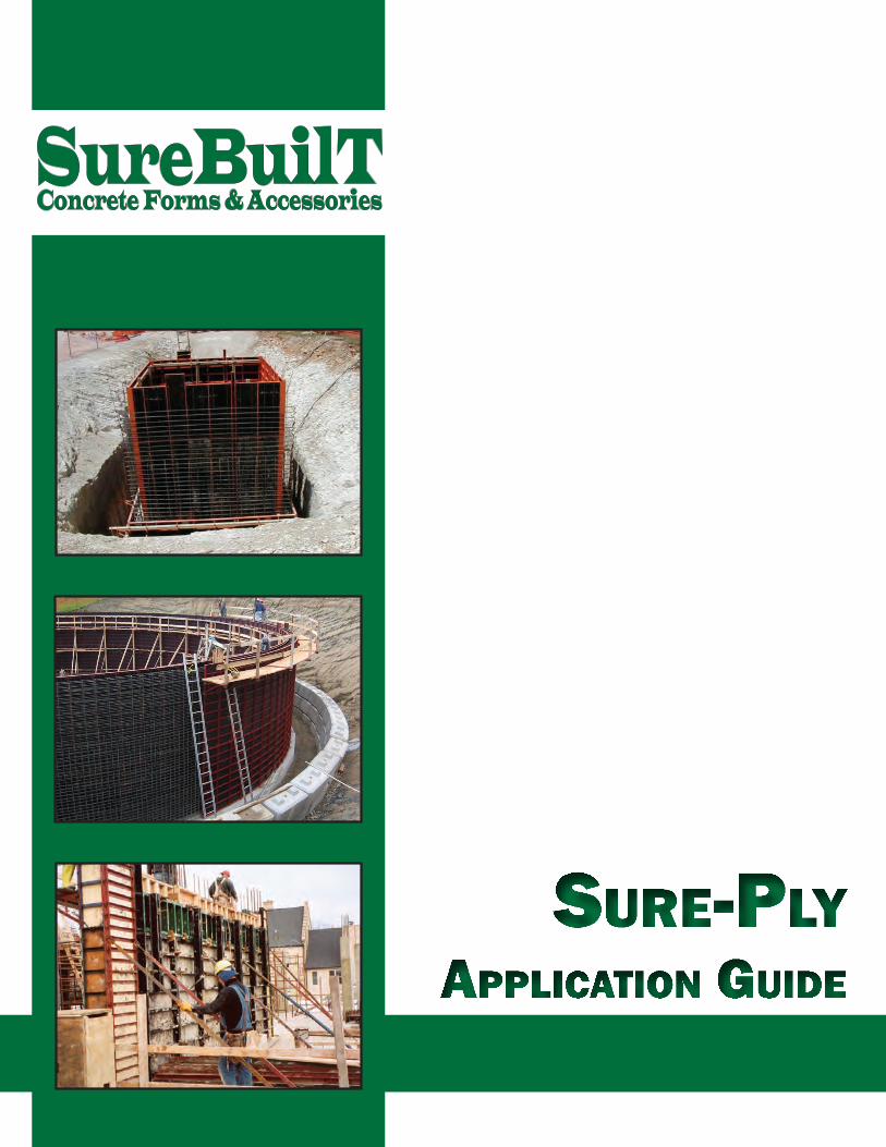
Angle struts are spaced on 12” centers to provide strength,
uniform concrete and minimize deflection.
1/2” plywood is riveted to angle struts. Plywood
tolerance is closely maintained to assure long form life.
Handles are provided on panels for easy handling in setting and
stripping forms
All panels are powder coated. In doing so the paint is baked into the panel which
allows for a long form-life and easy concrete clean-up.
1000 PSF System
2” wide angle strut allows for more weld for added strength.
Rear, side and end rail dados are located at 6” on center to
allow optimum accessory location.
ALL MATERIALS AND
MANUFACTURING
MADE IN USA
*
*
Front and rear rail contact points prevent grout
seepage and permit true form alignment with
adjacent panels.
*
PRODUCT FEATURES
Side and end rails are rolled from 55,000 p.s.i. steel and
welded continuously at corners for maximum strength.
Exact corner joints eliminate tolerance build-up over large
areas.
3 www.surebuilt‐usa.com • (708) 493 ‐ 9569
What follows is a basic illustration booklet showing the SURE-PLY system’s setting techniques,
hardware application and it’s versatility in reaction to difficult concrete forming projects.
NOTE: SureBuilt recommends the use of complete safety gear, gloves, safety shoes
and protective safety glasses when both erecting and dismantling forms.
The SURE-PLY forming system has a maximum pour pressure of 1000 lbs./ square foot.
BASIC PANEL AND FILLER SIZES:
Panels: 24” (wide) x 3’,4’,5’, 6’, 8’, 9’, 10’ (height)
Fillers: 4” to 22” (wide) x 3’,4’,5’, 6’, 8’, 9’, 10’ (height)
Metal Fillers: 1”, 1.5”, 2” (wide) x 3’,4’,5’, 6’, 8’, 9’, 10’ (height)
Inside Corner (metal): 6”x6” & 4”x4” (size) x 3’,4’,5’, 6’, 8’, 9’, 10’ (height)
Outside Corner: 3’,4’,5’, 6’, 8’, 9’, 10’ (height)
Filler Angles: 3’,4’,5’, 6’, 8’, 9’, 10’ (height)
Pilaster Panels: 3’,4’,5’, 6’, 8’, 9’, 10’ (height)
Culvert Forms: 3’,4’,5’, 6’, 8’, 9’, 10’ (height)
Inside & Outside Bay Corners: 3’,4’,5’, 6’, 8’, 9’, 10’ (height)
Hinge Corners: 3’,4’,5’, 6’, 8’, 9’, 10’ (height)
NOTE: Forms Available in feet/ inches & metric. (special order)
Custom forms are available to fit the needs of our customers.
Example: Custom column forms 30” to 24”, custom metal fillers 1” to 4” odd sizes, custom culvert
forms odd dimensions, custom adapter panel to other forming systems, etc.
Our system fits the needs of the customer with excellent quality, delivery and even choice of colors to
make your forms distinctive to your company.
INTRODUCTION
4 www.surebuilt‐usa.com • (708) 493 ‐ 9569
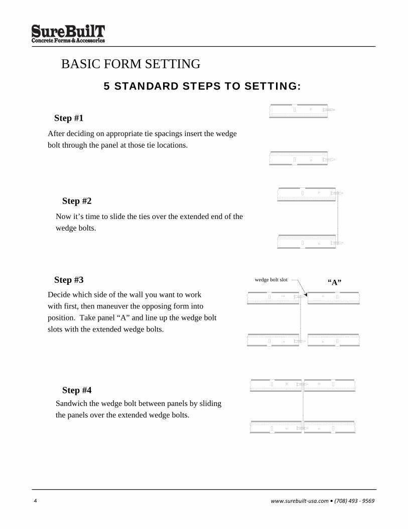
BASIC FORM SETTING 5 STANDARD STEPS TO SETTING:
After deciding on appropriate tie spacings insert the wedge
bolt through the panel at those tie locations.
Step #1
Now it’s time to slide the ties over the extended end of the
wedge bolts.
Step #2
Decide which side of the wall you want to work
with first, then maneuver the opposing form into
position. Take panel “A” and line up the wedge bolt
slots with the extended wedge bolts.
Step #3 “A” wedge bolt slot
Sandwich the wedge bolt between panels by sliding
the panels over the extended wedge bolts.
Step #4
5 www.surebuilt‐usa.com • (708) 493 ‐ 9569
BASIC FORM SETTING
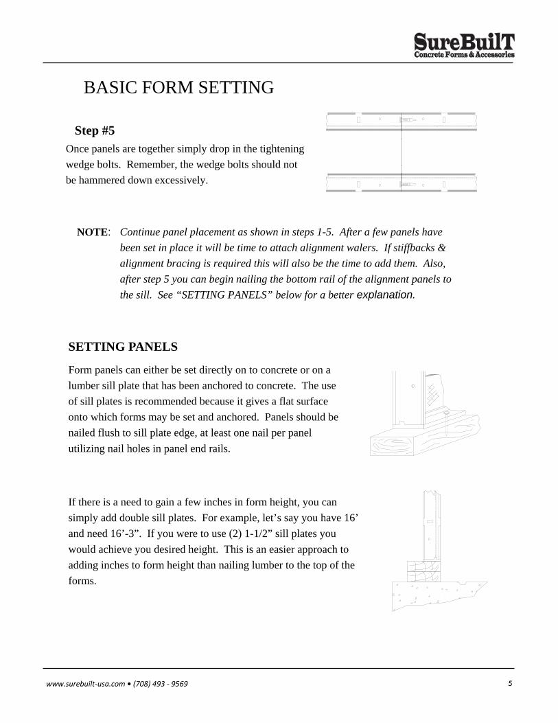
Form panels can either be set directly on to concrete or on a
lumber sill plate that has been anchored to concrete. The use
of sill plates is recommended because it gives a flat surface
onto which forms may be set and anchored. Panels should be
nailed flush to sill plate edge, at least one nail per panel
utilizing nail holes in panel end rails.
If there is a need to gain a few inches in form height, you can
simply add double sill plates. For example, let’s say you have 16’
and need 16’-3”. If you were to use (2) 1-1/2” sill plates you
would achieve you desired height. This is an easier approach to
adding inches to form height than nailing lumber to the top of the
forms.
Once panels are together simply drop in the tightening
wedge bolts. Remember, the wedge bolts should not
be hammered down excessively.
Step #5
Continue panel placement as shown in steps 1-5. After a few panels have
been set in place it will be time to attach alignment walers. If stiffbacks &
alignment bracing is required this will also be the time to add them. Also,
after step 5 you can begin nailing the bottom rail of the alignment panels to
the sill. See “SETTING PANELS” below for a better explanation.
NOTE:
SETTING PANELS
6 www.surebuilt‐usa.com • (708) 493 ‐ 9569
BASIC FORM SETTING
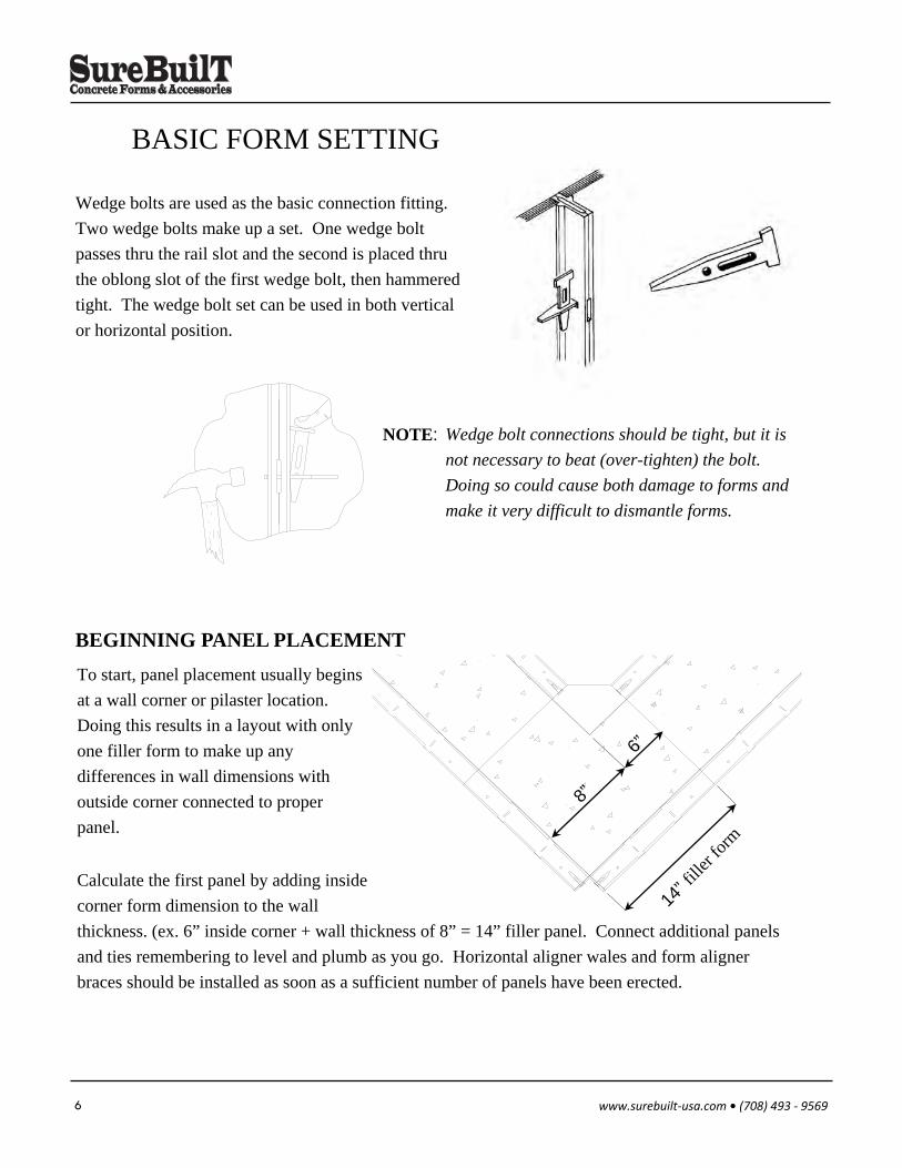
Wedge bolts are used as the basic connection fitting.
Two wedge bolts make up a set. One wedge bolt
passes thru the rail slot and the second is placed thru
the oblong slot of the first wedge bolt, then hammered
tight. The wedge bolt set can be used in both vertical
or horizontal position.
Wedge bolt connections should be tight, but it is
not necessary to beat (over-tighten) the bolt.
Doing so could cause both damage to forms and
make it very difficult to dismantle forms.
NOTE:
To start, panel placement usually begins
at a wall corner or pilaster location.
Doing this results in a layout with only
one filler form to make up any
differences in wall dimensions with
outside corner connected to proper
panel.
Calculate the first panel by adding inside
corner form dimension to the wall
thickness. (ex. 6” inside corner + wall thickness of 8” = 14” filler panel. Connect additional panels
and ties remembering to level and plumb as you go. Horizontal aligner wales and form aligner
braces should be installed as soon as a sufficient number of panels have been erected.
8”
6”
14” f
iller
form
BEGINNING PANEL PLACEMENT
7 www.surebuilt‐usa.com • (708) 493 ‐ 9569
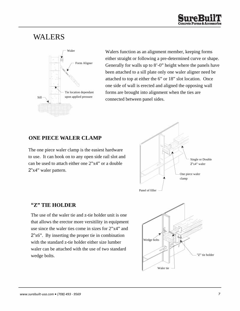
Walers function as an alignment member, keeping forms
either straight or following a pre-determined curve or shape.
Generally for walls up to 8’-0” height where the panels have
been attached to a sill plate only one waler aligner need be
attached to top at either the 6” or 18” slot location. Once
one side of wall is erected and aligned the opposing wall
forms are brought into alignment when the ties are
connected between panel sides.
WALERS
One piece waler
clamp
Panel of filler
Single or Double
2”x4” waler
The one piece waler clamp is the easiest hardware
to use. It can hook on to any open side rail slot and
can be used to attach either one 2”x4” or a double
2”x4” waler pattern.
ONE PIECE WALER CLAMP
The use of the waler tie and z-tie holder unit is one
that allows the erector more versitility in equipment
use since the waler ties come in sizes for 2”x4” and
2”x6”. By inserting the proper tie in combination
with the standard z-tie holder either size lumber
waler can be attached with the use of two standard
wedge bolts.
“Z” TIE HOLDER
Waler
Form Aligner
Tie location dependant
upon applied pressure Sill
“Z” tie holder
Wedge bolts
Waler tie
8 www.surebuilt‐usa.com • (708) 493 ‐ 9569
WALERS
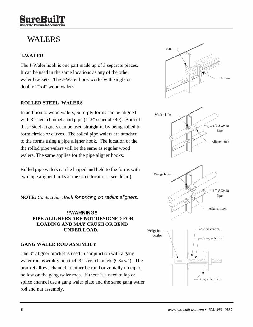
The J-Waler hook is one part made up of 3 separate pieces.
It can be used in the same locations as any of the other
waler brackets. The J-Waler hook works with single or
double 2”x4” wood walers.
J-WALER
The 3” aligner bracket is used in conjunction with a gang
waler rod assembly to attach 3” steel channels (C3x5.4). The
bracket allows channel to either be run horizontally on top or
bellow on the gang waler rods. If there is a need to lap or
splice channel use a gang waler plate and the same gang waler
rod and nut assembly.
!!WARNING!! PIPE ALIGNERS ARE NOT DESIGNED FOR
LOADING AND MAY CRUSH OR BEND UNDER LOAD.
In addition to wood walers, Sure-ply forms can be aligned
with 3” steel channels and pipe (1 ½” schedule 40). Both of
these steel aligners can be used straight or by being rolled to
form circles or curves. The rolled pipe walers are attached
to the forms using a pipe aligner hook. The location of the
the rolled pipe walers will be the same as regular wood
walers. The same applies for the pipe aligner hooks.
Rolled pipe walers can be lapped and held to the forms with
two pipe aligner hooks at the same location. (see detail)
ROLLED STEEL WALERS
NOTE: Contact SureBuilt for pricing on radius aligners.
GANG WALER ROD ASSEMBLY
J-waler
Nail
1 1/2 SCH40
Pipe
Aligner hook
Wedge bolts
1 1/2 SCH40
Pipe
Wedge bolts
Aligner hook
Wedge bolt
location Gang waler rod
Gang waler plate
3” steel channel
9 www.surebuilt‐usa.com • (708) 493 ‐ 9569
STRONG BACKS
Scaffold bracket
Waler
Strongback
Tie location dependant
upon applied pressure
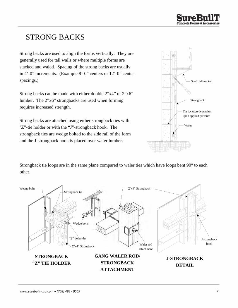
Strongback tie loops are in the same plane compared to waler ties which have loops bent 90° to each
other.
Strong backs are used to align the forms vertically. They are
generally used for tall walls or where multiple forms are
stacked and waled. Spacing of the strong backs are usually
in 4’-0” increments. (Example 8’-0” centers or 12’-0” center
spacings.)
Strong backs can be made with either double 2”x4” or 2”x6”
lumber. The 2”x6” strongbacks are used when forming
requires increased strength.
Strong backs are attached using either strongback ties with
“Z”-tie holder or with the “J”-strongback hook. The
strongback ties are wedge bolted to the side rail of the form
and the J-strongback hook is placed over waler lumber.
J-STRONGBACK
DETAIL
STRONGBACK
“Z” TIE HOLDER
GANG WALER ROD/
STRONGBACK
ATTACHMENT
“Z” tie holder
Wedge bolts Strongback tie
2”x4” Strongback
2”x4” Strongback
Waler rod
attachment
Wedge bolts
J strongback
hook
10 www.surebuilt‐usa.com • (708) 493 ‐ 9569
STACKING FORMS
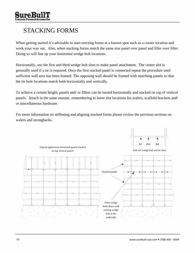
When getting started it’s advisable to start erecting forms at a known spot such as a corner location and
work your way out. Also, when stacking forms match the same size panel over panel and filler over filler.
Doing so will line up your horizontal wedge bolt locations.
Horizontally, use the first and third wedge bolt slots to make panel attachment. The center slot is
generally used if a tie is required. Once the first stacked panel is connected repeat the procedure until
sufficient wall area has been framed. The opposing wall should be framed with matching panels so that
the tie hole locations match both horizontally and vertically.
To achieve a certain height, panels and/ or fillers can be turned horizontally and stacked on top of vertical
panels. Attach in the same manner, remembering to leave slot locations for,walers, scaffold brackets and/
or miscellaneous hardware.
For more information on stiffening and aligning stacked forms please review the previous sections on
walers and strongbacks.
1st 2nd 3rd
End rail wedge bolt and tie slots
Stacked panels
Point wedge
bolts down with
locking wedge
bolt at the
underside
Typical application horizontal panels stacked
on top vertical panels
11 www.surebuilt‐usa.com • (708) 493 ‐ 9569
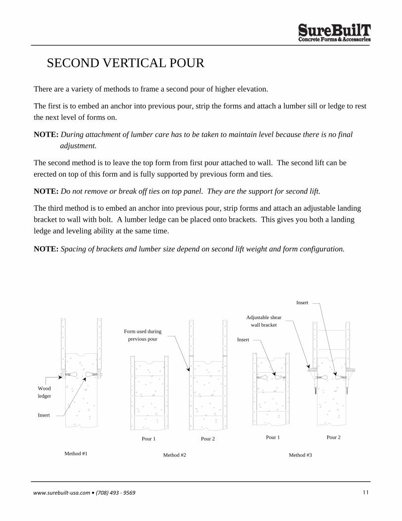
SECOND VERTICAL POUR
There are a variety of methods to frame a second pour of higher elevation.
The first is to embed an anchor into previous pour, strip the forms and attach a lumber sill or ledge to rest
the next level of forms on.
NOTE: During attachment of lumber care has to be taken to maintain level because there is no final
adjustment.
The second method is to leave the top form from first pour attached to wall. The second lift can be
erected on top of this form and is fully supported by previous form and ties.
NOTE: Do not remove or break off ties on top panel. They are the support for second lift.
The third method is to embed an anchor into previous pour, strip forms and attach an adjustable landing
bracket to wall with bolt. A lumber ledge can be placed onto brackets. This gives you both a landing
ledge and leveling ability at the same time.
NOTE: Spacing of brackets and lumber size depend on second lift weight and form configuration.
Method #1 Method #2 Method #3
Wood
ledger
Insert
Form used during
previous pour
Pour 2 Pour 1 Pour 2 Pour 1
Insert
Adjustable shear
wall bracket
Insert

12 www.surebuilt‐usa.com • (708) 493 ‐ 9569
FORM ALIGNMENT Form aligners are required to position forms straight and plumb. They are never used to hold concrete
pressure or any other load. Depending on forming requirements, there are several methods to align forms.
The second method is the use of a adjustable turn buckle form
aligner. Again, use attachment plate and wood aligner, but it is nailed
to the turn buckle and allows contractor to adjust a maximum of 6”.
The third method of form aligning is handled by using Sure-ply’s
tubular steel mini brace. It is made with standard stake foot on one
end and has a Sure-ply attachment plate on the other end. It
extends from 7’-6” to 11’-6” and at each setting allows you 12” of
adjustment.
The final method is for tall walls or column forming. Standard pipe brace ranging from 14’-0”
to 39’-0” are available.
NOTE: Depending on application SureBuilt can manufacture any style attachment
hardware you require.
The first method is steel or
wooden stake along with
attachment plate and
lumber aligner all nailed
together. There’s no
adjustment with this
method of form aligning.
Form aligner
Stake
Waler
2” x 4”
Attachment plate
Wedge bolt
Turn buckle
Turn buckle
Stake
Wedge bolt
13 www.surebuilt‐usa.com • (708) 493 ‐ 9569
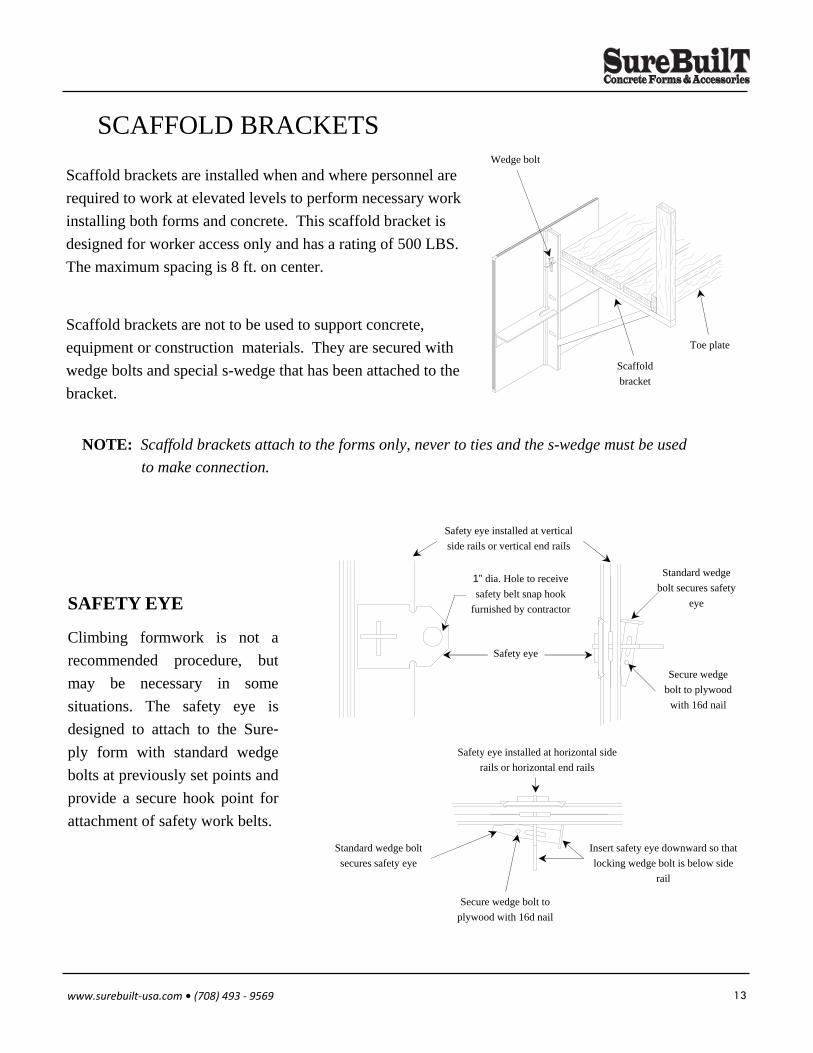
SCAFFOLD BRACKETS
Scaffold brackets are installed when and where personnel are
required to work at elevated levels to perform necessary work
installing both forms and concrete. This scaffold bracket is
designed for worker access only and has a rating of 500 LBS.
The maximum spacing is 8 ft. on center.
SAFETY EYE
Scaffold brackets are not to be used to support concrete,
equipment or construction materials. They are secured with
wedge bolts and special s-wedge that has been attached to the
bracket.
NOTE: Scaffold brackets attach to the forms only, never to ties and the s-wedge must be used
to make connection.
Wedge bolt
Scaffold
bracket
Toe plate
Safety eye
Safety eye installed at vertical
side rails or vertical end rails
1” dia. Hole to receive
safety belt snap hook
furnished by contractor
Standard wedge
bolt secures safety
eye
Secure wedge
bolt to plywood
with 16d nail
Climbing formwork is not a
recommended procedure, but
may be necessary in some
situations. The safety eye is
designed to attach to the Sure-
ply form with standard wedge
bolts at previously set points and
provide a secure hook point for
attachment of safety work belts.
Insert safety eye downward so that
locking wedge bolt is below side
rail
Safety eye installed at horizontal side
rails or horizontal end rails
Secure wedge bolt to
plywood with 16d nail
Standard wedge bolt
secures safety eye
14 www.surebuilt‐usa.com • (708) 493 ‐ 9569
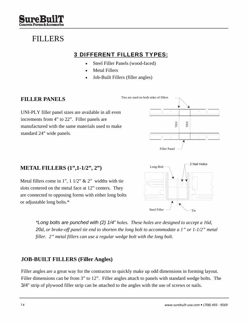
FILLERS
3 DIFFERENT FILLERS TYPES: Steel Filler Panels (wood-faced)
Metal Fillers
Job-Built Fillers (filler angles)
FILLER PANELS
UNI-PLY filler panel sizes are available in all even
increments from 4” to 22”. Filler panels are
manufactured with the same materials used to make
standard 24” wide panels.
Ties are used on both sides of fillers
TIE
S
TIE
S
Filler Panel
Filler angles are a great way for the contractor to quickly make up odd dimensions in forming layout.
Filler dimensions can be from 3” to 12”. Filler angles attach to panels with standard wedge bolts. The
3/4” strip of plywood filler strip can be attached to the angles with the use of screws or nails.
JOB-BUILT FILLERS (Filler Angles)
METAL FILLERS (1”,1-1/2”, 2”)
Metal fillers come in 1”, 1 1/2” & 2” widths with tie
slots centered on the metal face at 12” centers. They
are connected to opposing forms with either long bolts
or adjustable long bolts.*
Steel Filler Tie
Long-Bolt 2 Nail Holes
*Long bolts are punched with (2) 1/4” holes. These holes are designed to accept a 16d,
20d, or broke-off panel tie end to shorten the long bolt to accommodate a 1” or 1-1/2” metal
filler. 2” metal fillers can use a regular wedge bolt with the long bolt.
15 www.surebuilt‐usa.com • (708) 493 ‐ 9569
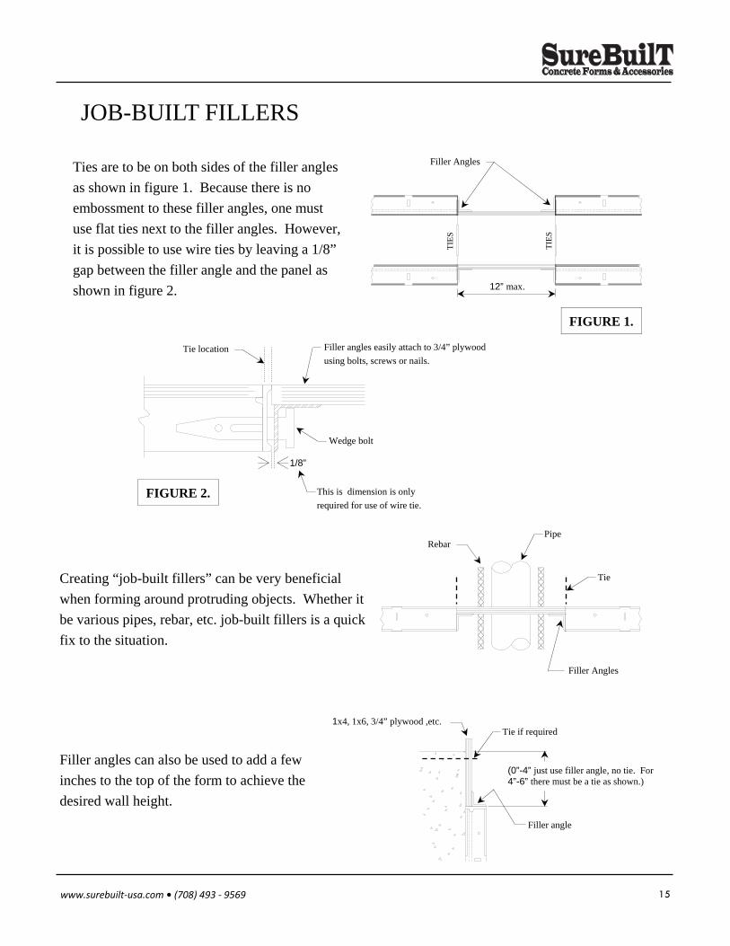
JOB-BUILT FILLERS
Ties are to be on both sides of the filler angles
as shown in figure 1. Because there is no
embossment to these filler angles, one must
use flat ties next to the filler angles. However,
it is possible to use wire ties by leaving a 1/8”
gap between the filler angle and the panel as
shown in figure 2.
FIGURE 2.
Tie location Filler angles easily attach to 3/4” plywood
using bolts, screws or nails.
Wedge bolt
This is dimension is only
required for use of wire tie.
1/8”
FIGURE 1.
Filler Angles
TIE
S
TIE
S
12” max.
Creating “job-built fillers” can be very beneficial
when forming around protruding objects. Whether it
be various pipes, rebar, etc. job-built fillers is a quick
fix to the situation.
Pipe Rebar
Filler Angles
Tie
Filler angles can also be used to add a few
inches to the top of the form to achieve the
desired wall height.
(0”-4” just use filler angle, no tie. For 4”-6” there must be a tie as shown.)
Tie if required
Filler angle
1x4, 1x6, 3/4” plywood ,etc.
16 www.surebuilt‐usa.com • (708) 493 ‐ 9569
BASIC FORM SETTING
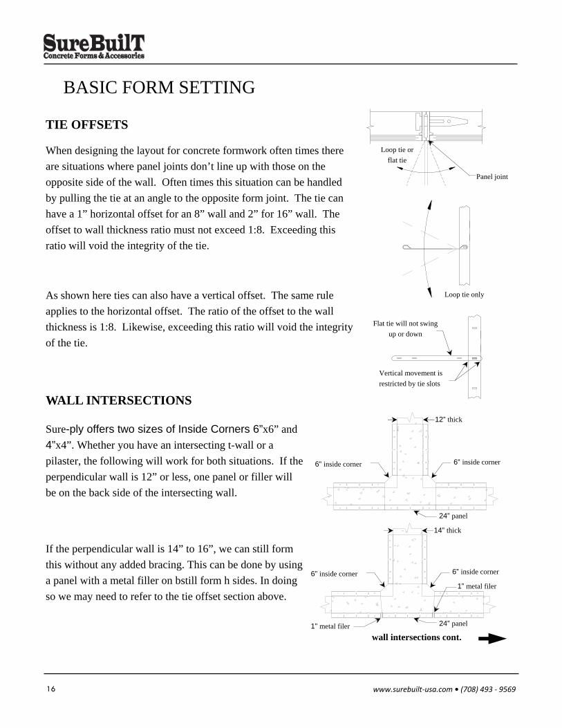
Sure-ply offers two sizes of Inside Corners 6”x6” and
4”x4”. Whether you have an intersecting t-wall or a
pilaster, the following will work for both situations. If the
perpendicular wall is 12” or less, one panel or filler will
be on the back side of the intersecting wall.
WALL INTERSECTIONS
If the perpendicular wall is 14” to 16”, we can still form
this without any added bracing. This can be done by using
a panel with a metal filler on bstill form h sides. In doing
so we may need to refer to the tie offset section above.
wall intersections cont.
TIE OFFSETS
When designing the layout for concrete formwork often times there
are situations where panel joints don’t line up with those on the
opposite side of the wall. Often times this situation can be handled
by pulling the tie at an angle to the opposite form joint. The tie can
have a 1” horizontal offset for an 8” wall and 2” for 16” wall. The
offset to wall thickness ratio must not exceed 1:8. Exceeding this
ratio will void the integrity of the tie.
As shown here ties can also have a vertical offset. The same rule
applies to the horizontal offset. The ratio of the offset to the wall
thickness is 1:8. Likewise, exceeding this ratio will void the integrity
of the tie.
Loop tie or
flat tie
Panel joint
Loop tie only
Flat tie will not swing
up or down
Vertical movement is
restricted by tie slots
12” thick
24” panel
6” inside corner 6” inside corner
6” inside corner
14” thick
6” inside corner
24” panel
1” metal filer
1” metal filer
17 www.surebuilt‐usa.com • (708) 493 ‐ 9569
BASIC FORM SETTING
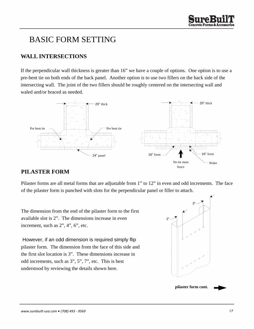
If the perpendicular wall thickness is greater than 16” we have a couple of options. One option is to use a
pre-bent tie on both ends of the back panel. Another option is to use two fillers on the back side of the
intersecting wall. The joint of the two fillers should be roughly centered on the intersecting wall and
waled and/or braced as needed.
WALL INTERSECTIONS
PILASTER FORM
The dimension from the end of the pilaster form to the first
available slot is 2”. The dimensions increase in even
increment, such as 2”, 4”, 6”, etc.
However, if an odd dimension is required simply flip
pilaster form. The dimension from the face of this side and
the first slot location is 3”. These dimensions increase in
odd increments, such as 3”, 5”, 7”, etc. This is best
understood by reviewing the details shown here.
Pilaster forms are all metal forms that are adjustable from 1” to 12” in even and odd increments. The face
of the pilaster form is punched with slots for the perpendicular panel or filler to attach.
pilaster form cont.
20” thick
Pre bent tie Pre bent tie
24” panel 16” form 16” form
Waler
20” thick
No tie must
brace
2”
3”
18 www.surebuilt‐usa.com • (708) 493 ‐ 9569
BASIC FORM SETTING
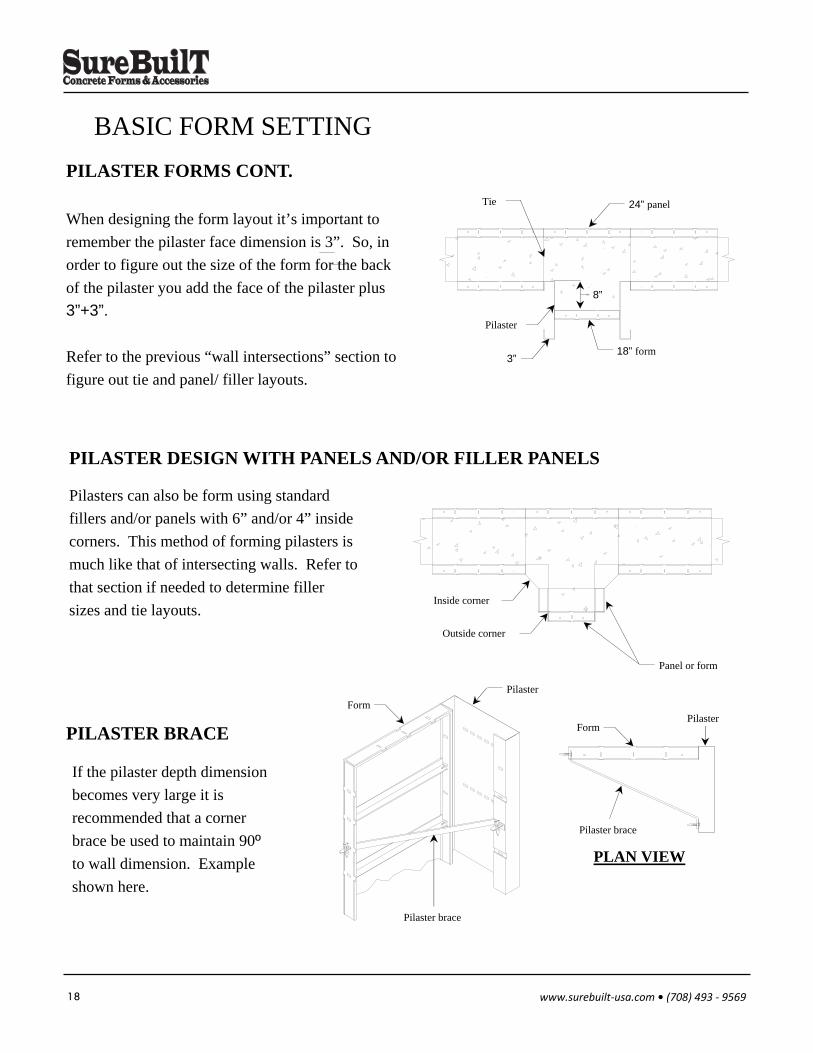
Pilasters can also be form using standard
fillers and/or panels with 6” and/or 4” inside
corners. This method of forming pilasters is
much like that of intersecting walls. Refer to
that section if needed to determine filler
sizes and tie layouts.
PILASTER DESIGN WITH PANELS AND/OR FILLER PANELS
When designing the form layout it’s important to
remember the pilaster face dimension is 3”. So, in
order to figure out the size of the form for the back
of the pilaster you add the face of the pilaster plus
3”+3”.
Refer to the previous “wall intersections” section to
figure out tie and panel/ filler layouts.
PILASTER FORMS CONT.
If the pilaster depth dimension
becomes very large it is
recommended that a corner
brace be used to maintain 90º
to wall dimension. Example
shown here.
PILASTER BRACE
Outside corner
Panel or form
Inside corner
24” panel
18” form
8”
Tie
3”
Pilaster
PLAN VIEW
Pilaster Form
Pilaster brace
Form
Pilaster brace
Pilaster
19 www.surebuilt‐usa.com • (708) 493 ‐ 9569
FOOTINGS (FORMING, STEP & SLOPING)
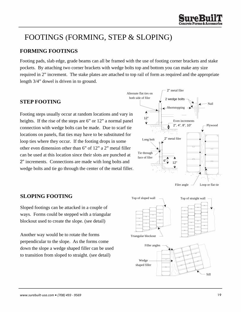
Footing pads, slab edge, grade beams can all be framed with the use of footing corner brackets and stake
pockets. By attaching two corner brackets with wedge bolts top and bottom you can make any size
required in 2” increment. The stake plates are attached to top rail of form as required and the appropriate
length 3/4” dowel is driven in to ground.
FORMING FOOTINGS
Sloped footings can be attacked in a couple of
ways. Forms could be stepped with a triangular
blockout used to create the slope. (see detail)
Another way would be to rotate the forms
perpendicular to the slope. As the forms come
down the slope a wedge shaped filler can be used
to transition from sloped to straight. (see detail)
SLOPING FOOTING
Triangular blockout
Top of sloped wall Top of straight wall
Filler angles
Wedge
shaped filler
Sill
Footing steps usually occur at random locations and vary in
heights. If the rise of the steps are 6” or 12” a normal panel
connection with wedge bolts can be made. Due to scarf tie
locations on panels, flat ties may have to be substituted for
loop ties where they occur. If the footing drops in some
other even dimension other than 6” of 12” a 2” metal filler
can be used at this location since their slots are punched at
2” increments. Connections are made with long bolts and
wedge bolts and tie go through the center of the metal filler.
STEP FOOTING 2 wedge bolts
Shortstopping
2” metal filer Alternate flat ties on
both side of filer
Even increments
2”, 4”, 8”, 10”
Nail
12”
Long bolt 2” metal filer
Tie through
face of filer
12” 6”
Plywood
Filer angle Loop or flat tie
20 www.surebuilt‐usa.com • (708) 493 ‐ 9569
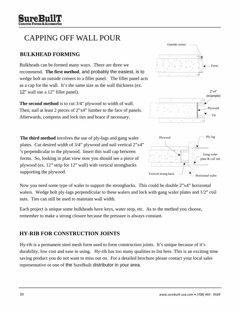
CAPPING OFF WALL POUR
Bulkheads can be formed many ways. There are three we
recommend. The first method, and probably the easiest, is to
wedge bolt an outside corners to a filler panel. The filler panel acts
as a cap for the wall. It’s the same size as the wall thickness (ex.
12” wall use a 12” filler panel).
BULKHEAD FORMING
The second method is to cut 3/4” plywood to width of wall.
Then, nail at least 2 pieces of 2”x4” lumber to the face of panels.
Afterwards, compress and lock ties and brace if necessary.
Each project is unique some bulkheads have keys, water stop, etc. As to the method you choose,
remember to make a strong closure because the pressure is always constant.
The third method involves the use of ply-lags and gang waler
plates. Cut desired width of 3/4” plywood and nail vertical 2”x4”
’s perpendicular to the plywood. Insert this wall cap between
forms. So, looking in plan view now you should see a piece of
plywood (ex. 12” strip for 12” wall) with vertical strongbacks
supporting the plywood.
Now you need some type of waler to support the strongbacks. This could be double 2”x4” horizontal
walers. Wedge bolt ply-lags perpendicular to these walers and lock with gang waler plates and 1/2” coil
nuts. Ties can still be used to maintain wall width.
HY-RIB FOR CONSTRUCTION JOINTS
Hy-rib is a permanent steel mesh form used to form construction joints. It’s unique because of it’s
durability, low cost and ease in using. Hy-rib has too many qualities to list here. This is an exciting time
saving product you do not want to miss out on. For a detailed brochure please contact your local sales
representative or one of the SureBuilt distributor in your area.
Outside corner
Form
2”x4”
(example)
Tie
Plywood
Ply lag
Gang waler
plate & coil nut
Horizontal waler Vertical strong back
Plywood
21 www.surebuilt‐usa.com • (708) 493 ‐ 9569
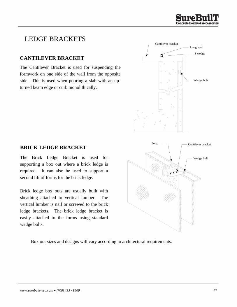
LEDGE BRACKETS
CANTILEVER BRACKET
The Cantilever Bracket is used for suspending the
formwork on one side of the wall from the opposite
side. This is used when pouring a slab with an up-
turned beam edge or curb monolithically.
The Brick Ledge Bracket is used for
supporting a box out where a brick ledge is
required. It can also be used to support a
second lift of forms for the brick ledge.
Brick ledge box outs are usually built with
sheathing attached to vertical lumber. The
vertical lumber is nail or screwed to the brick
ledge brackets. The brick ledge bracket is
easily attached to the forms using standard
wedge bolts.
BRICK LEDGE BRACKET
Box out sizes and designs will vary according to architectural requirements.
Cantilever bracket Long bolt
S wedge
Wedge bolt
Cantilever bracket Form
Wedge bolt
22 www.surebuilt‐usa.com • (708) 493 ‐ 9569
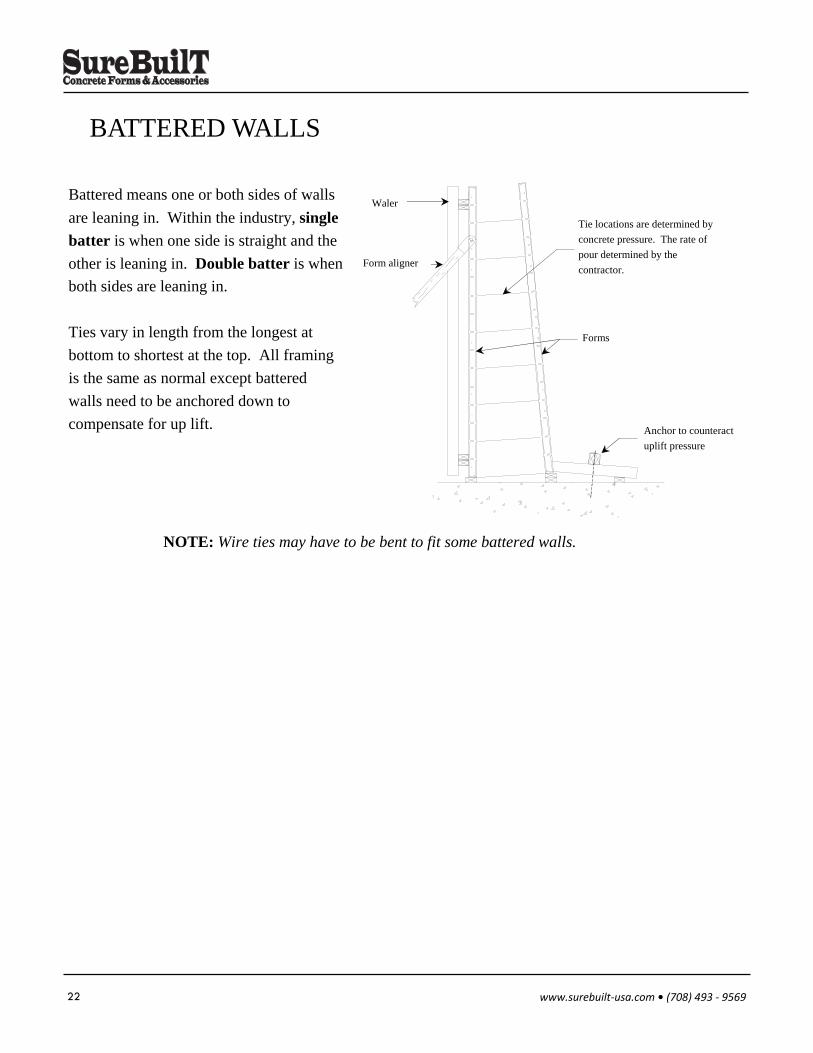
BATTERED WALLS
Battered means one or both sides of walls
are leaning in. Within the industry, single
batter is when one side is straight and the
other is leaning in. Double batter is when
both sides are leaning in.
Ties vary in length from the longest at
bottom to shortest at the top. All framing
is the same as normal except battered
walls need to be anchored down to
compensate for up lift.
NOTE: Wire ties may have to be bent to fit some battered walls.
Form aligner
Waler
Tie locations are determined by
concrete pressure. The rate of
pour determined by the
contractor.
Forms
Anchor to counteract
uplift pressure
23 www.surebuilt‐usa.com • (708) 493 ‐ 9569
OUTSIDE/ HINGED/ BAY/ CORNERS
OUTSIDE CORNERS
Outside corners are steel angles used to attach perpendicular outside forms. The outside corner is
attached to the forms with standard wedge bolts. These wedge bolts are placed at the same elevation as
the ties. To avoid hitting wedge bolts when attaching to the forms insert the wedge bolt from the outside
corner toward the form. This way the perpendicular wedge bolt can bear on the cross member and the
adjacent wedge bolt has clearance.
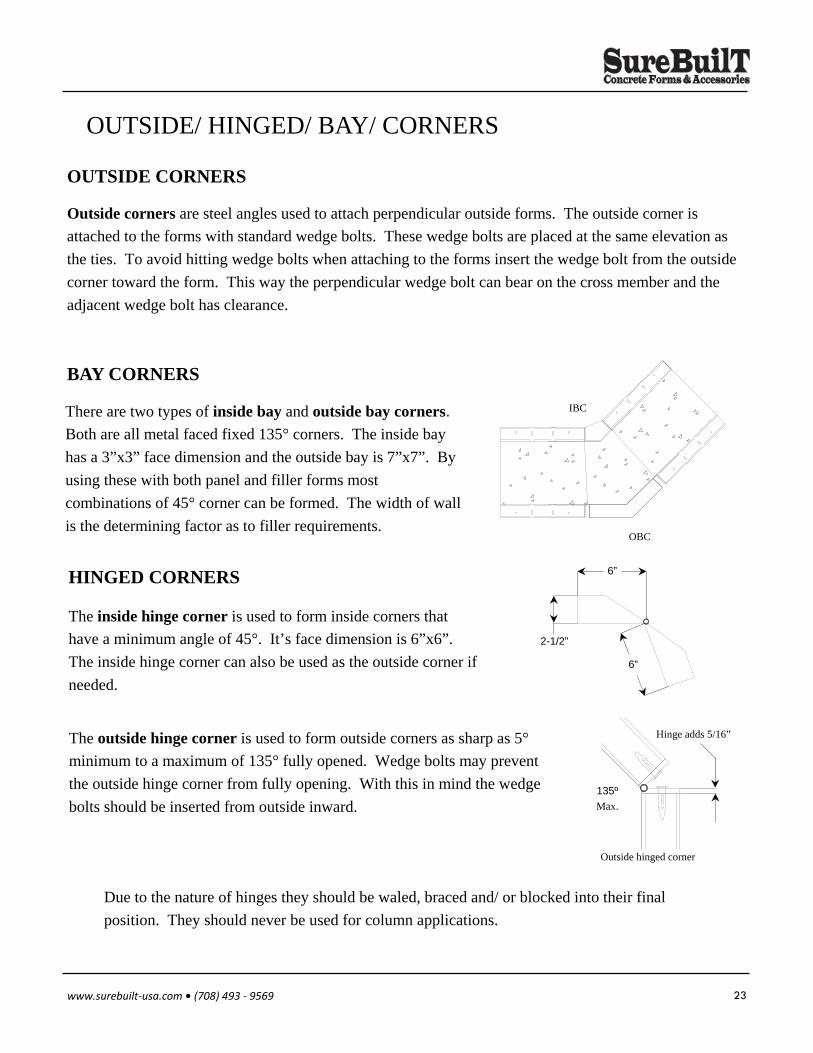
The outside hinge corner is used to form outside corners as sharp as 5°
minimum to a maximum of 135° fully opened. Wedge bolts may prevent
the outside hinge corner from fully opening. With this in mind the wedge
bolts should be inserted from outside inward.
There are two types of inside bay and outside bay corners.
Both are all metal faced fixed 135° corners. The inside bay
has a 3”x3” face dimension and the outside bay is 7”x7”. By
using these with both panel and filler forms most
combinations of 45° corner can be formed. The width of wall
is the determining factor as to filler requirements.
BAY CORNERS
HINGED CORNERS
The inside hinge corner is used to form inside corners that
have a minimum angle of 45°. It’s face dimension is 6”x6”.
The inside hinge corner can also be used as the outside corner if
needed.
Due to the nature of hinges they should be waled, braced and/ or blocked into their final
position. They should never be used for column applications.
135º
Max.
Outside hinged corner
Hinge adds 5/16”
IBC
OBC
6”
2-1/2”
6”
24 www.surebuilt‐usa.com • (708) 493 ‐ 9569
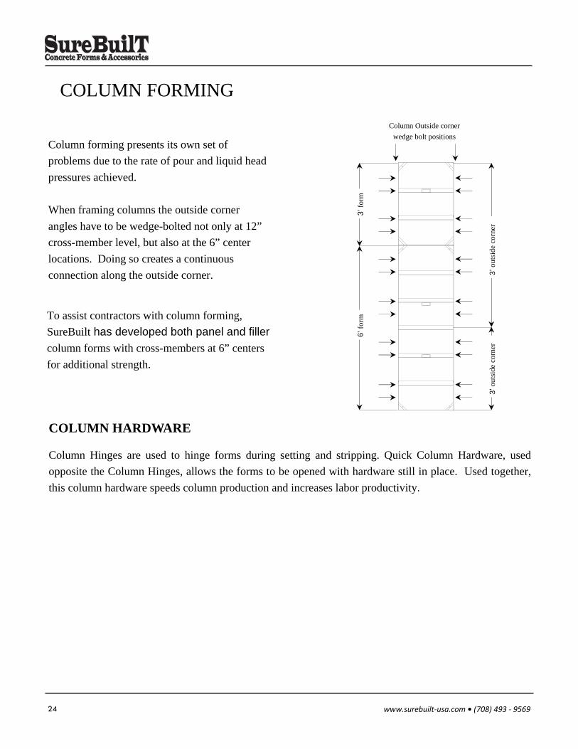
COLUMN FORMING
Column forming presents its own set of
problems due to the rate of pour and liquid head
pressures achieved.
When framing columns the outside corner
angles have to be wedge-bolted not only at 12”
cross-member level, but also at the 6” center
locations. Doing so creates a continuous
connection along the outside corner.
To assist contractors with column forming,
SureBuilt has developed both panel and filler
column forms with cross-members at 6” centers
for additional strength.
Column Hinges are used to hinge forms during setting and stripping. Quick Column Hardware, used
opposite the Column Hinges, allows the forms to be opened with hardware still in place. Used together,
this column hardware speeds column production and increases labor productivity.
COLUMN HARDWARE
Column Outside corner
wedge bolt positions
3’ f
orm
3’ o
utsi
de c
orne
r
6’ f
orm
3’ o
utsi
de c
orne
r
25 www.surebuilt‐usa.com • (708) 493 ‐ 9569
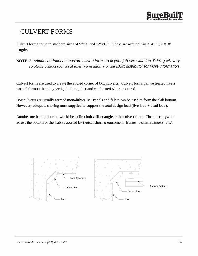
CULVERT FORMS
Culvert forms come in standard sizes of 9”x9” and 12”x12”. These are available in 3’,4’,5’,6’ & 8’
lengths.
NOTE: SureBuilt can fabricate custom culvert forms to fit your job-site situation. Pricing will vary
so please contact your local sales representative or SureBuilt distributor for more information.
Culvert forms are used to create the angled corner of box culverts. Culvert forms can be treated like a
normal form in that they wedge-bolt together and can be tied where required.
Box culverts are usually formed monolithically. Panels and fillers can be used to form the slab bottom.
However, adequate shoring must supplied to support the total design load (live load + dead load).
Another method of shoring would be to first bolt a filler angle to the culvert form. Then, use plywood
across the bottom of the slab supported by typical shoring equipment (frames, beams, stringers, etc.).
Culvert form
Form
Shoring system Culvert form
Form
Form (shoring)
26 www.surebuilt‐usa.com • (708) 493 ‐ 9569
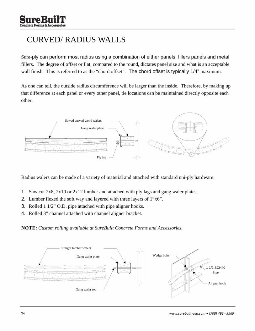
Sure-ply can perform most radius using a combination of either panels, fillers panels and metal
fillers. The degree of offset or flat, compared to the round, dictates panel size and what is an acceptable
wall finish. This is referred to as the “chord offset”. The chord offset is typically 1/4” maximum.
As one can tell, the outside radius circumference will be larger than the inside. Therefore, by making up
that difference at each panel or every other panel, tie locations can be maintained directly opposite each
other.
CURVED/ RADIUS WALLS
Radius walers can be made of a variety of material and attached with standard uni-ply hardware.
1. Saw cut 2x8, 2x10 or 2x12 lumber and attached with ply lags and gang waler plates.
2. Lumber flexed the soft way and layered with three layers of 1”x6”.
3. Rolled 1 1/2” O.D. pipe attached with pipe aligner hooks.
4. Rolled 3” channel attached with channel aligner bracket.
NOTE: Custom rolling available at SureBuilt Concrete Forms and Accessories.
Sawed curved wood walers
Gang waler plate
Ply lag
Straight lumber walers
Gang waler plate
Gang waler rod
1 1/2 SCH40
Pipe
Wedge bolts
Aligner hook
27 www.surebuilt‐usa.com • (708) 493 ‐ 9569
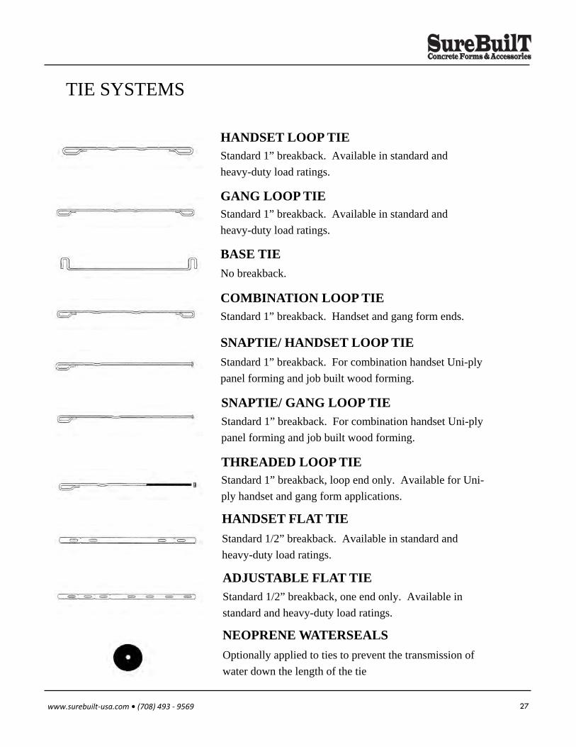
TIE SYSTEMS
Standard 1” breakback. Available in standard and
heavy-duty load ratings.
HANDSET LOOP TIE
Standard 1” breakback. Available in standard and
heavy-duty load ratings.
GANG LOOP TIE
No breakback.
BASE TIE
Standard 1” breakback. Handset and gang form ends.
COMBINATION LOOP TIE
Standard 1” breakback. For combination handset Uni-ply
panel forming and job built wood forming.
SNAPTIE/ HANDSET LOOP TIE
Standard 1” breakback. For combination handset Uni-ply
panel forming and job built wood forming.
SNAPTIE/ GANG LOOP TIE
Standard 1” breakback, loop end only. Available for Uni-
ply handset and gang form applications.
THREADED LOOP TIE
Standard 1/2” breakback. Available in standard and
heavy-duty load ratings.
HANDSET FLAT TIE
Standard 1/2” breakback, one end only. Available in
standard and heavy-duty load ratings.
ADJUSTABLE FLAT TIE
Optionally applied to ties to prevent the transmission of
water down the length of the tie
NEOPRENE WATERSEALS
28 www.surebuilt‐usa.com • (708) 493 ‐ 9569
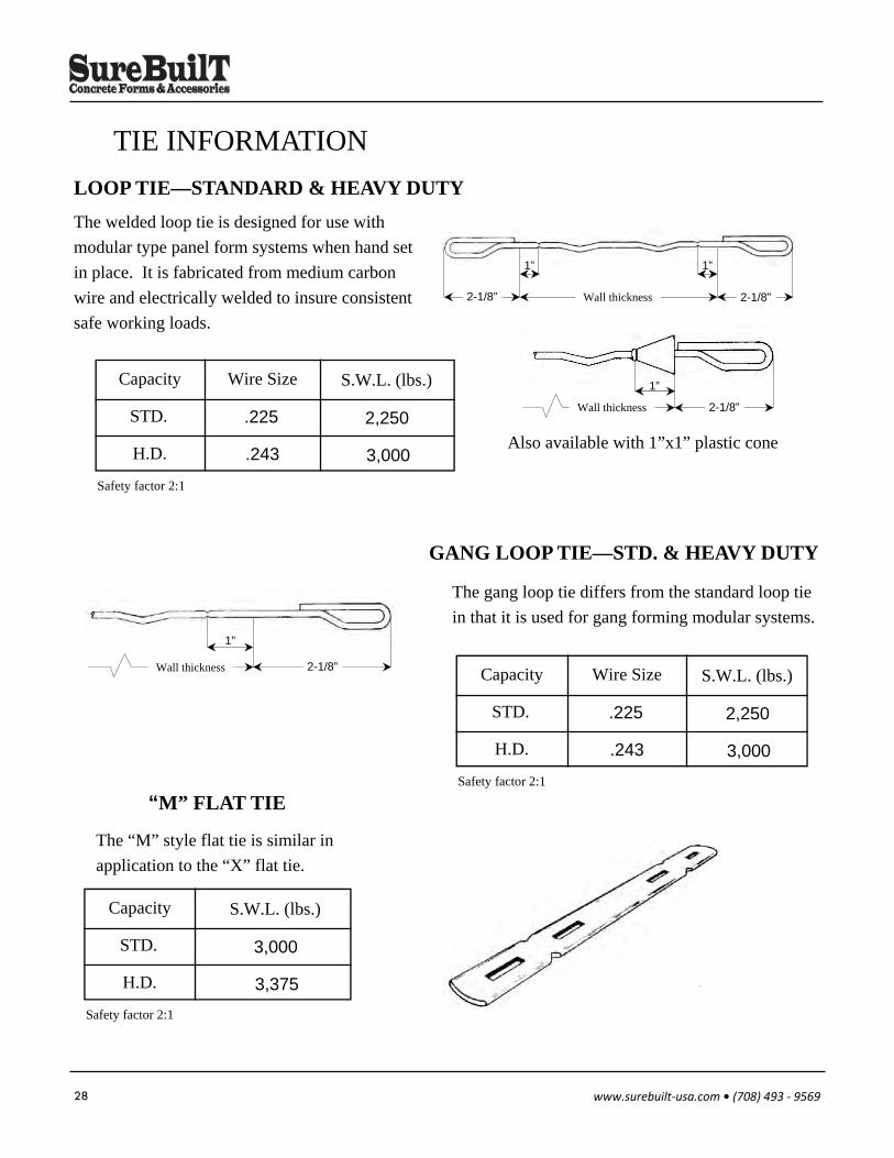
TIE INFORMATION LOOP TIE—STANDARD & HEAVY DUTY
The welded loop tie is designed for use with
modular type panel form systems when hand set
in place. It is fabricated from medium carbon
wire and electrically welded to insure consistent
safe working loads.
Capacity
STD.
H.D.
Wire Size
.225
.243
S.W.L. (lbs.)
2,250
3,000
Safety factor 2:1
“M” FLAT TIE
Capacity
STD.
H.D.
S.W.L. (lbs.)
3,000
3,375
Safety factor 2:1
The “M” style flat tie is similar in
application to the “X” flat tie.
Also available with 1”x1” plastic cone
GANG LOOP TIE—STD. & HEAVY DUTY
Capacity
STD.
H.D.
Wire Size
.225
.243
S.W.L. (lbs.)
2,250
3,000
Safety factor 2:1
The gang loop tie differs from the standard loop tie
in that it is used for gang forming modular systems.
1” 1”
2-1/8” 2-1/8” Wall thickness
Wall thickness
1”
2-1/8”
Wall thickness
1”
2-1/8”
29 www.surebuilt‐usa.com • (708) 493 ‐ 9569
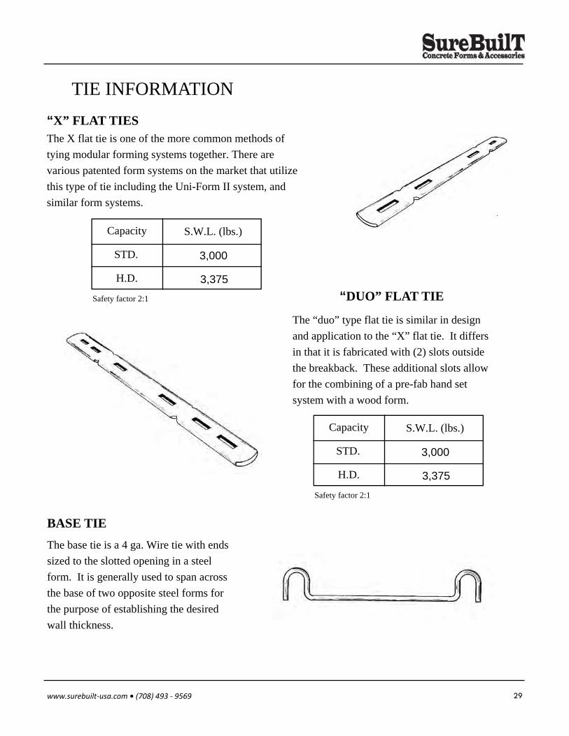
BASE TIE
The base tie is a 4 ga. Wire tie with ends
sized to the slotted opening in a steel
form. It is generally used to span across
the base of two opposite steel forms for
the purpose of establishing the desired
wall thickness.
“DUO” FLAT TIE
Capacity
STD.
H.D.
S.W.L. (lbs.)
3,000
3,375
Safety factor 2:1
The “duo” type flat tie is similar in design
and application to the “X” flat tie. It differs
in that it is fabricated with (2) slots outside
the breakback. These additional slots allow
for the combining of a pre-fab hand set
system with a wood form.
“X” FLAT TIES
Capacity
STD.
H.D.
S.W.L. (lbs.)
3,000
3,375
Safety factor 2:1
The X flat tie is one of the more common methods of
tying modular forming systems together. There are
various patented form systems on the market that utilize
this type of tie including the Uni-Form II system, and
similar form systems.
TIE INFORMATION
30 www.surebuilt‐usa.com • (708) 493 ‐ 9569
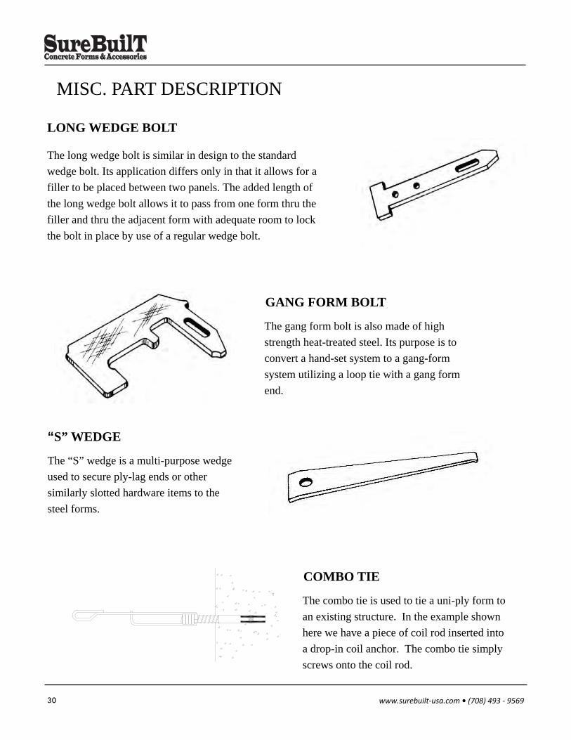
MISC. PART DESCRIPTION
The gang form bolt is also made of high
strength heat-treated steel. Its purpose is to
convert a hand-set system to a gang-form
system utilizing a loop tie with a gang form
end.
GANG FORM BOLT
The long wedge bolt is similar in design to the standard
wedge bolt. Its application differs only in that it allows for a
filler to be placed between two panels. The added length of
the long wedge bolt allows it to pass from one form thru the
filler and thru the adjacent form with adequate room to lock
the bolt in place by use of a regular wedge bolt.
LONG WEDGE BOLT
The “S” wedge is a multi-purpose wedge
used to secure ply-lag ends or other
similarly slotted hardware items to the
steel forms.
“S” WEDGE
The combo tie is used to tie a uni-ply form to
an existing structure. In the example shown
here we have a piece of coil rod inserted into
a drop-in coil anchor. The combo tie simply
screws onto the coil rod.
COMBO TIE
31 www.surebuilt‐usa.com • (708) 493 ‐ 9569
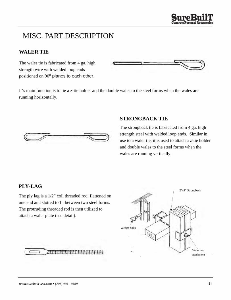
STRONGBACK TIE
The strongback tie is fabricated from 4 ga. high
strength steel with welded loop ends. Similar in
use to a waler tie, it is used to attach a z-tie holder
and double wales to the steel forms when the
wales are running vertically.
WALER TIE
The waler tie is fabricated from 4 ga. high
strength wire with welded loop ends
positioned on 90º planes to each other.
It’s main function is to tie a z-tie holder and the double wales to the steel forms when the wales are
running horizontally.
The ply lag is a 1/2” coil threaded rod, flattened on
one end and slotted to fit between two steel forms.
The protruding threaded rod is then utilized to
attach a waler plate (see detail).
PLY-LAG 2”x4” Strongback
Waler rod
attachment
Wedge bolts
MISC. PART DESCRIPTION
32 www.surebuilt‐usa.com • (708) 493 ‐ 9569
The real key to ganging is the gang form tie and gang form bolt. The tie length is extend past the form
edge to allow you to break of ties with out disassembling gang units.
The gang tie is inserted and passed through both opposite panels and one end locked using gang form
bolt. It is important that the gang form bolt be inserted and latched properly. Remember that if the short
end of welded wire loop faces up insert bolt from left, if it faces down insert from right. Also if after
locking one end you find the opposite end sticking out past or short of panel slot do not hammer or force
bolt, welds can be damaged or cracked without any sign and could cause a tie failure.
Double duty lift bracket provides a attachment point for lifting rigging it attachment directly to panel
insertions with wedge bolt, and has a 2000 lbs rated capacity.
Large sections of uni ply forms are assembled first, then crane moved into position to pour a wall section.
Gang forming uses the same basic hardware as hand set, but offers great advantages to contractor. Gangs
are easily assembled on ground, they strip as a unit, they are reusable without disassembly for more pours,
they are light approx 7 lbs per sq ft assembled.
Gangs are assembled by placing panels face down on a flat surface. The horizontal walers are laid out to
fall below the horizontal joints the wedge bolt connections are made 6” from corner and 6” from mid
point of side rail.
Walers and stiff backs are usually 2”x4” but can also be 2”x6” or 2”x8”. The total depth between waler
and stiff back should not exceed 12”. Since the wooden waler and stiff back are used for alignment only
few are required, but they should be located as not to infer eith tie placement. They are attached with one
of the following methods gang waler rods or J-strong back rod.
GANG FORMING
What SureBuilt considers heavy gang forming with uni-ply forms is a gang system that utilizes
taper ties, she bolts and inner rods coupled with the use of all steel channel system of walers and stiff
backs. The use of both 3” horizontal channel and either 5” or 8” stiff back allows for the use of heavy tie
systems at greater spacing. The panel plywood does have to be drilled to allow tie to pass through to
make connection to opposite gang, and you have to decrees the spacing of 3” dbl channel walers to 2’-0”
O/C.
33 www.surebuilt‐usa.com • (708) 493 ‐ 9569
STRIPPING FORMS
Usually form stripping can begin after all connecting hardware has been removed. It is easiest to begin at
a relief point such as an outside corner, metal filer or filer angle connection.
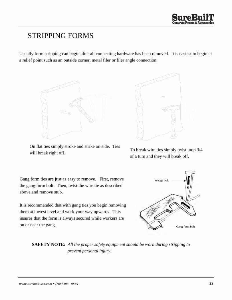
On flat ties simply stroke and strike on side. Ties
will break right off. To break wire ties simply twist loop 3/4
of a turn and they will break off.
Gang form ties are just as easy to remove. First, remove
the gang form bolt. Then, twist the wire tie as described
above and remove stub.
It is recommended that with gang ties you begin removing
them at lowest level and work your way upwards. This
insures that the form is always secured while workers are
on or near the gang.
SAFETY NOTE: All the proper safety equipment should be worn during stripping to
prevent personal injury.
Wedge bolt
Gang form bolt
34 www.surebuilt‐usa.com • (708) 493 ‐ 9569
ADJUSTABLE TURNBUCKLE ALIGNER
ATTACHMENT PLATE
BASE TIE
BAY CORNER
BRICK LEDGE BRACKET
BULKHEAD FORMING
CANTILEVER BRACKET
COMBO TIE
CONSTRUCTION JOINTS
CULVERT FORM
DUO FLAT TIES
FILLER PANELS
FILLERS
FOOTINGS
FORM ALIGNMENT
GANG FORM BOLT
GANG FORMING
GANG LOOP TIE
GANG WALER PLATE
GANG WALER ROD ASSEMBLY
INSIDE HINGE CORNER
JOB BUILT FILLERS
J-STRONGBACK DETAIL
J-WALER
LONGE WEDGE BOLT
LOOP TIE
METAL FILLERS
M-FLAT TIE
MINI BRACE ALIGNER
12
12
29
23
21
20
21
30
20
25
29
14
14
19
12
30
32
28
26
8,9
23
14
9
8
30
28
14
28
12
ONE PIECE WALER CLAMP
OUTSIDE CORNER
OUTSIDE HINGE CORNER
PILASTER BRACE
PILASTER DESIGNRADIUS WALL
PILASTER FORM
PLY-LAG
RADIUS WALL
ROLLED STEEL WALERS
SAFETY EYE
SCAFFOLD BRACKETS
SECOND VERTICAL POUR
SETTING PANELS
SLOPE FOOTING
STACKING FORMS
STEP FOOTING
STRIPPING FORMS
STRONGBACK TIE
STRONGBACK Z-TIE HOLDER
STRONGBACKS
S-WEDGE BOLT
TIE OFFSETS
TIES
WALER TIE
WALERS
WALL INTERSECTIONS
X-FLAT TIE
Z-TIE HOLDER
7
23
23
18
18
17
31
26
8
13
13
11
5
19
10
19
33
31
9
9
30
16
27
31
7
16
29
7
INDEX
35 www.surebuilt‐usa.com • (708) 493 ‐ 9569
LIMITED WARRANTY SureBuilt Concrete Forms & Accessories (hereafter known as Supplier) warrants that the Supplier of concrete
accessory products sold to Purchaser will be free from defects in materials and workmanship for a period of six (6)
months from the date of delivery, and the Supplier will repair, or in its sole discretion, replace, any Product or part
thereof found to be defective at the time of delivery if such Product or part is returned (at Purchaser’s expense and
risk) and received by the Supplier within ten (10) days after the applicable warranty period. Descriptions, representa-
tions and other information concerning the Supplier contained in the Supplier’s catalogs, advertisements or other
promotional materials or statements or representations made by the Supplier’s sales agents or representatives shall
not be binding upon the Supplier and shall not be part of this limited warranty unless expressly identified in writing as
PRODUCT SPECIFICATIONS.
This limited warranty does not cover normal maintenance, or items consumed during installation or normal oper-
ations, normal wear and tear, use under circumstances exceeding specifications, use for purposes other than the
use for which the Products were intended, abuse, unauthorized repair or alteration, improper installation, failure to
follow the Supplier’s printed instructions, guidelines and recommendations for installation and use, lack of proper
maintenance or damage caused by natural causes such as fire, storm, or flood. Purchaser shall determine the suita-
bility of the Product for his intended use and Purchaser assumes all liabilities and risks whatsoever in connection
therewith.
This limited warranty is Purchaser’s exclusive remedy. It shall not be deemed to have failed of its essential pur-
pose so long as the Supplier is willing and able to repair or replace defective products or parts thereof in the manner
specified. No allowance will be made or repairs made by Purchaser.
Except as herein provided, the Supplier shall not be liable to Purchaser in any manner with respect to the Prod-
ucts. In no event shall the Supplier liability to Purchaser ever exceed the purchase price of the allegedly defective
Product. Except as herein provided, the Supplier shall not be liable for transportation, labor or other charges for ad-
justments, repairs, replacements of parts, installation, or other work, which may be done upon or in connection with
the Products sold.
THE SUPPLIER SHALL NOT IN ANY EVENT BE LIABLE FOR INCIDENTAL OR CONSEQUENTIAL DAMAG-
ES OF ANY NATURE WHATSOEVER, INCLUDING LOST PROFITS, whether arising from any defect in the Prod-
ucts, any use of the Products, from Purchaser’s inability to use the Products, or otherwise. This limited warranty ap-
plies to only products made by the Supplier.
NO OTHER EXPRESS AND NO IMPLIED WARRANTIES OF ANY TYPE, WHETHER FOR MERCHANTABIL-
ITY, FITNESS FOR A PARTICULAR USE, OR OTHERWISE, OTHER THANTHOSE EXPRESSLY SET FORTH
ABOVE (WHICH ARE MADE EXPRESSLY IN LIEU OF ALL OTHER WARRANTIES) SHALL APPLY TO THE
PRODUCTS.

840 South 25th Ave • Bellwood Il 60104 Phone 708.493.9569 • FAx 708.493.9601
www.SureBuIlt-uSA.com


![UIDE - partselectcom.azureedge.net · UIDE iiiii i a _ Installer:Pleaseleave this manual with i] thisConsumer:appliance,Pleaseread and keepthis ... any other equipment using electricityand](https://img.pdfslide.us/doc/110x75/5b92170b09d3f211298d35d8/uide-uide-iiiii-i-a-installerpleaseleave-this-manual-with-i-thisconsumerappliancepleaseread.jpg)