Embed Size (px)
Citation preview

Sprinkler Systems Installation GuideUser Guide for Geberit Mapress Pipework Installations to LPC Rules for Automatic Sprinkler Installations (incorporating BS EN 12845). Valid from 1. August 2011

1 Introduction 3
1.1 TheGeberitMapresspressfittingjoint 3
2 Components 4
2.1 GeberitMapresssystemcomponents 4 2.2 GeberitMapressStainlessSteel 4 2.2.1 GeberitMapressStainlessSteelpressfitings 4 2.2.2 GeberitMapressStainlessSteelsystempipes 4 2.3 GeberitMapressCarbonSteel 5 2.3.1 GeberitMapressCarbonSteelpressfittingsgalvanised 5 2.3.2 GeberitMapressCarbonSteelsystempipes 5 2.4 GeberitMapresspressingtools 5
3 Applicationsandplanningguidelines 6
3.1 InstallationinaccordancewithLPCB 6 3.2 Systemlayout 9 3.3 Hazardclassifications 9 3.4 Connectionstomainswater 9 3.5 Pipesupports 10 3.6 Calculationofpressurelossesinpipework 10 3.6.1 Equivalentpipelengths 11 3.7 Expansioncompensation 15 3.7.1 CalculatingexpansioninMapressStainlessSteel 16 3.7.2 CalculatingexpansioninMapressCarbonSteel 20 3.8 Layingtechniques 24 3.9 Wallpenetrations 24
4 Installation 25
4.1 Tooling 25 4.2 Transportandstorage 25 4.3 MakingaMapresspressconnection 25
4.4 Preparethepipeandfittingforthepressingoperation 26
5 Commissioning 30
5.1 Bendingthesystempipes 30 5.2 Connections 30 5.3 Flushingthepipes 30 5.4 Pressureandleaktest 30 5.5 Refillingandair-bleedingofthepipesystemforcommissioning 30 5.6 Compatibilityofadditives 30 5.7 Compatiblepaintsandcoatings 31 5.8 Maintenance 31 5.9 Servicelife 31
6 Supportservices 32
6.1 Geberittechnicalservice 32 6.2 Training 32U
serG
uideforG
eberitMapressPipew
orkInstallationstoLPCRules
forA
utom
aticSprinklerInstallations(incorporatingBSEN12845)
Contents
2
3
SprinklerSystemsInstallationGuideIntroduction
1IntroductionAutomaticsprinklersystemsaredesignedforthepurpose
ofdetectingandsuppressingorextinguishingafireas
earlyaspossibleduringitsinitialphasesothatitcanbe
safelyextinguishedusingothermeans.Thesesuppression
systemsandcomponentsaresubjecttospecial
requirementsbythecertifyingbodies.
LPCBapprovedGeberitMapresspipesandfittings
intendedforuseinsprinklersystemsinaccordancewiththe
LPCRulesforAutomaticSprinklerInstallationsareavailable
withanominaldiameterofDN20toDN100instainless
steelandcarbonsteel(internally&externallygalvanised).
WiththeGeberitMapresspressfittingpipeandfittings
system,pressingthefittingandpipetogetherproducesa
permanentandhigh-strengthpipejoint.Thepermanent
tightnessoftheconnectionisachievedbytheseal
ringsthatareinsertedintothepressfittingbeadbythe
manufacturer.Thesystemhasbeenusedsince1969
innon-alloysteelforclosedheatingsystemsandsince
1985instainlesssteelfordrinkingwatersystems.Since
thentheproductrangeofGeberitMapresspressfitting
productsforapplicationsintheareasofbuildingservices
andindustryaswellasinmarineapplicationshasbeen
continuouslyexpanded.GeberitMapresshasbeenwidely
usedinsprinklersystemsacrossEuropesince1984and
in2011hasreceivedLPCBapproval.
OtherGeberitMapressproductsoutsidetherange
approvedbyLPCBandintendedforuseintheLPCrules
forautomaticsprinklerinstallationscanbefoundinthe
GeberitSupplySystemsProductGuideandincludes
GeberitMapressCuNiFe,aseawaterresistantcopper-
nickelalloy.Forwaterextinguishingsystems,pipeswith
anominaldiameterofDN20toDN100areavailablein
stainlesssteel,carbonsteelinternally/externallygalvanised
andCuNiFe.
TheGeberitMapresspressfittingsystemismanufactured
tomeetthedesignandinstallationrequirementsof
buildingfireprotection.
Thesesystemsincludethefollowingcomponents:
•GeberitMapresspressfittings
•GeberitMapresssystempipes
•GeberitMapresspressingtools.
1.1 TheGeberitMapresspressfittingjoint
Thepressfitting,withsealringsfactory-fittedintheends,
isthebasicelementofthesystem.TheGeberitMapress
systempipeisinsertedintothepressfittingsasfarasthe
specifiedinsertiondistance.Thejointiscreatedusingthe
GeberitMapresspressingtool.
Thepressingoperationhasanimpactontwolevels.
Firstly,themechanicalstrengthoftheconnectionis
achieved.Secondly,theo-ringensuresthewatertightseal
oftheconnection.
Figure 1: Section through a pressfitting joint with the pressing jaw (hexagonal pressing contour) still in position.
Figure 2: Section through a pressfitting joint with the pressing collar (lemon shaped pressing contour) still in position.
seal ring
A
press�tting
pressing jaw
A
pipe A-A
tightness strength level
press�tting
pressing collar
tightnessstrength level
pipe A-A
seal ring
A
A
seal ring
A
press�tting
pressing jaw
A
pipe A-A
tightness strength level
press�tting
pressing collar
tightnessstrength level
pipe A-A
seal ring
A
A

SprinklerSystemsInstallationGuideComponents
2 Components
2.1 GeberitMapresssystem componentsTheindividualcomponentsoftheMapresssystemare
carefullymatched.Infireprotectionsystems,Geberit
Mapresspressfittingsmaythereforeonlybeusedin
conjunctionwithGeberitMapresssystempipesand
pressingtools.Sizes,weightsandpackageunitscanbe
foundintheGeberitproductcatalogue.
Thefittingendsareprovidedwithapressingindicatorin
thefactory.Thepressingindicatorisdestroyedbythe
pressingprocedureandshallsubsequentlybemanually
removedbytheinstallerafterpressing.
Thepressingindicatorhasthefollowingfunctions:
• Indicatestotheinstaller,beforethepressuretest,
thatthereareunpressedconnections
• Displaysthedimensionsofthefittingsinan
unpressedstate
• ClearlyidentifiesthefittingasaGeberitproductin
anunpressedstate
• Indicatesthematerialofthefittingbyitscolour-blue
forstainlesssteelandredforcarbonsteelinan
unpressedstate.
AllMapressfittingsalsocomewithaprotectionplugon
eachend.Thisprotectsthesealringfromdustanddirt,
increasinghygieneandsafety.
2.2 GeberitMapress StainlessSteelTheGeberitMapressStainlessSteelpressfittingsystem
isLPCBapprovedforuseinwetsprinklersystems
totheLPCRulesforAutomaticSprinklerInstallations.
Thesystemcanbeinstalleddirectlyinconcrete.
GeberitMapressStainlessSteelislistedundertheWater
RegulationsAdvisorySchemeforuseindrinkingwater
installations.CertificateNo:0610086.
2.2.1 GeberitMapressStainlessSteel
pressfittingsGeberitMapressStainlessSteelpressfittings,also
freeofsilicone,aremadeofhigh-alloyed316steel,
X5CrNiMo17-12-2inaccordancewithDINEN10088,
materialno.1.4401/AISI316.Allfittingsaresolutionand
brightannealedtoincreasecorrosionresistance.The
stainlesssteelpressconnectorsleakifunpressedandare
markedwiththemanufacturercodeaswellaswiththe
LPCBcertificationmarks(onthepackaginglabel).
2.2.2GeberitMapressStainless SteelsystempipesGeberitMapressStainlessSteelsystempipesare
madeofthesamehighquality316steelasthe
pressfittings.Afactorystandardensuresthatadditional
increasedrequirementsaremet:
• Increasedmolybdenumcontent,atleast2.2%
• Weldseamadditionallysmoothedontheinside,
solutionandbrightannealedforincreasedcorrosion
protection
• Pipelength6m
• Canbecoldbent(seesection5.1).
TheybeartheLPCB,FM,TUVandDVGWcertification
marks.Thethin-walledpipesandpressfittingslead
toaweightreductionofabout50%comparedto
conventionalstandardpipework.
Table1:Pipedimensionsinstainlesssteel
4
Ø=outsidediameter
s=wallthickness
Size(mm)
DN Øxs(mm) Weight(kg/m)
20 22.0x1.2 0.626
25 28.0x1.2 0.806
32 35.0x1.2 1.260
40 42.0x1.5 1.523
50 54.0x1.5 1.974
65 76.1x2.0 3.715
80 89.9x2.0 4.357
100 108.0x2.0 5.315

SprinklerSystemsInstallationGuideComponents
2.3 GeberitMapress CarbonSteelTheGeberitMapresspressfittingsystemmadeofcarbon
steel,isLPCBapprovedforuseinwetsprinklersystems
totheLPCRulesforAutomaticSprinklerInstallations.
2.3.1 GeberitMapressCarbon Steelpressfittings, galvanisedTheGeberitMapressCarbonSteelpressfittingsaremade
ofnon-alloysteel,materialno.1.0034,inaccordancewith
DINEN10305.Theyaregalvanicallyzinc-platedwitha
protectivelayer(Fe/Zn8B,bluechromated)thatisatleast
8μmthick.Furthermore,GeberitMapressCarbonSteel
pressfittingsleakifunpressedandaremarkedwithared
pressingindicator.Theybearthemanufacturercodeas
wellastheLPCB,VdSandFMCertificationmarks(onthe
packaginglabel).
2.3.2 GeberitMapressCarbonSteelsystempipesinternally/externally
galvanisedTheGeberitMapresssystempipemadeofnon-alloysteel,
materialno.1.0215,isathin-walled,weldedand
internally/externallygalvanisedprecisionsteelpipethat
alsomeetstherequirementsoftheGeberitMapress
factorystandardconcerningdimensionalaccuracyand
surfacequality.Thesepipesaremanufacturedfrommetal
stripsgalvanisedonbothsides.
Thethicknessofthezinclayerontheinternalaswellas
theexternalsurfaceis15–27μm[zinc275g/m2].
Theappliedzincplatingprocessproducesasmooth,
high-densityzinclayer,freeofmicroscopicgapsand
cavitiesforevenbetteranti-corrosionproperties.
Theweldingseamontheoutsideofthepipeis
subsequentlygalvanised.Thepipesaremarked,among
otherthings,withthemanufacturercodeaswellas
withtheLPCB,FMandVdSCertificationmarks(onthe
packaginglabel).Thethin-walledpipesandpressfittings
leadtoaweightreductionofabout50%comparedto
conventionalstandardpipework.
Table2:Pipedimensionsinnon-alloysteel,internally/externallygalvanised
2.4 GeberitMapress pressingtoolsDependingonthediameterandworkingpressureofthe
installation,theGeberitMapresspipejointsaremade
usingdifferentGeberitMapresspressingtools(seetable3
formoredetails).
Ø=outsidediameter
s=wallthickness
5
Size(mm)
DN Øxs(mm) Weight(kg/m)
20 22.0x1.2 0.758
25 28.0x1.2 0.980
32 35.0x1.2 1.239
40 42.0x1.5 1.498
50 54.0x1.5 1.942
65 76.1x2.0 3.655
80 89.9x2.0 4.286
100 108.0x2.0 5.228

SprinklerSystemsInstallationGuideApplicationsandplanningguidelines
GeberitMapressCarbonSteelpressfittingswiththe
standardblackbutylrubbersealring(CIIR)inconjunction
withtheinternally/externallygalvanisedsystempipeare
LPCBapprovedforuseinaccordancewiththeLPCRules
forAutomaticSprinklerInstallationsinwetsystemswith
pressures12to16bar,dependingonthedimensionsand
pressfittingtoolused(seeTable3).ForafulllistofLPCB
approvedGeberitproducts,pleasereferto
www.redbooklive.comorseeTables4-5.
Table3:InstallationinaccordancewithLPCBapproval
6
Table4:LPCBapprovedGeberitMapressStainlessSteelSprinklerPipeworkSystemComponents
Description Size/mm
Pipe 22,28,35,42,54,76.1,88.9,108
Coupling 22,28,35,42,54,76.1,88.9,108
SlipCoupling 22,28,35,42,54,76.1,88.9,108
Bend90° 22,28,35,42,54,76.1,88.9,108
Bend90°withplainend 22,28,35,42,54,76.1,88.9,108
Bend45° 22,28,35,42,54,76.1,88.9,108
Bend45°withplainend 22,28,35,42,54,76.1,88.9,108
Reducerwithplainend 28x22,35x22,35x28,42x28,42x35,
54x35,54x42,76.1x54,88.9x54
88.9x76.1,108x76.1,108x88.9
T-pieceequal 22,28,35,42,54,76.1,88.9,108
3 Applicationsand planningguidelinesTheseinstallationinstructionsapplytoGeberitMapress
pressfittingsystemsmadeofstainlesssteelandnon-alloy
steelgalvanisedinaccordancewithLPCRulesforAutomatic
SprinklerInstallationsincorporatingBSEN12845.
FordetailsregardingtheinstallationofGeberitMapressfor
sprinklersystemsinaccordancetoVdSandFMapproval,
pleasecontactGeberitdirectly.
Toassistyouwiththeplanning,youcandownloadCAD
dataforthepressfittingsindxfordwgformatfromthe
ServicesectionoftheGeberithomepage.
3.1 Installationinaccordance withLPCBGeberitMapressStainlessSteelpressfittingsandsystem
pipesareLPCBapprovedforuseinaccordancewiththe
LPCRulesforAutomaticSprinklerInstallations.
Theapprovalcoverswetsystemsatoperatingpressures
uptoeither12or16bar,dependingonthedimensions
andpressfittingtoolused(seeTable3)inconjunctionwith
theblackbutylrubbersealring(CIIR).
WorkingPressure(bar)
1216
Ø(mm)
Tool HCPS ECO301 HCPS ECO301
22 XY XY
28 XY XY
35* XY XY
42 XY XY
54 XY XY
76.1 XY XY X
88.9 XY XY X
108 XY
X=stainlesssteelY=carbonsteel
*35mmpressingcollartobeusedarticleno:90538
SprinklerSystemsInstallationGuideApplicationsandplanningguidelines
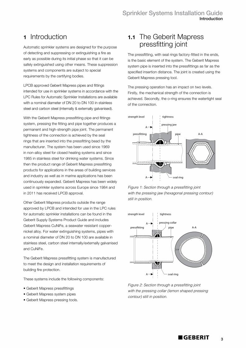
Table4:Continued
LPCBapprovallistingnotes
1.TheaboveGeberitPress-fitpipeworkandfittingsaretobeinstalledusingtheECO301andHCPSpressingtoolsonly,inaccordancewiththeGeberitInstallationInstructions.Thesetoolsshallbeservicedandmaintainedinaccordancewithmanufacturers’statedguidelines.
2. GeberitPress-fitpipeworkandfittingsmayonlybeinstalledbyLPCBapprovedorregisteredcontractorswhohaveundergoneadequatetrainingbythemanufacturer.3. GeberitPress-fitpipeworkandfittingsshallbeinstalledinaccordancewiththeGeberitInstallationInstructions,Issue1.July20114. GeberitPress-fitpipeworkandfittingsshallbeinstalledandmaintainedinconformancewiththeLPCRulesforAutomaticSprinklerInstallations.5. TheuseofGeberitPress-fitpipeworkandfittingsshallberecordedonLPS1048certificatesofconformity.6.WhereaGeberitReducerisinstalled,apipehangershallbeusedadjacenttothereduceronthelargerpipe.7.WhereGeberitsystempipeworkisconnectedtosprinklersinsuspendedceilingsusingflexibledrops,onlyLPCBApprovedflexibledropsshallbeused.8. GeberitPress-fitpipeworkandfittingsarenotcompatiblewithlightweightpipingsystemsfromothermanufacturers.
7
Description Size/mm
T-piecereduced 28x22x28,35x22x35,35x28x35,42x22x42
42x28x42,42x35x42,54x22x54,54x28x54
54x35x54,54x42x54,76.1x22x76.1,76.1x28x76.1
76.1x35x76.1,76.1x42x76.1,76.1x54x76.1,88.9x22x88.9
88.9x28x88.9,88.9x35x88.9,88.9x42x88.9,88.9x54x88.9
88.9x76.1x88.9,108x22x108,108x28x108,108x35x108
108x42x108,108x54x108,108x76.1x108,108x88.9x108
T-piecewithfemalethread 22x½”x22,22x¾”x22,28x½”x28,28x¾”x28,
28x1”x28,35x½”x35,35x¾”x35,42x½”x42
42x¾”x42,54x½”x54,54x¾”x54,54x2”x54
76.1x¾”x76.1,76.1x2”x76.1,88.9x¾”x88.9,88.9x2”x88.9
108x¾”x108,108x2”x108
Adaptorwithmalethread 22x½”,22x¾”,22x1”,28x¾”,28x1”,28x1¼”,
35x1”,35x1¼”,35x1½”,42x1¼”,42x1½”
54x1½”,54x2”,76.1x2½”,88.9x3”
Adaptorwithfemalethread 22x½”,22x¾”,22x1”,28x½”,28x¾”,28x1”
28x1¼”,35x1”
35x1¼”,35x1½”,42x1¼”,
42x1½”
54x1½”,54x2”
Adaptorwithbrassunionnut 22x1”,22x1¼”,22x1½”,28x1”,28x1¼”
28x1½”,35x1½”,42x1¾”,54x2³/8”,76.1x3”,88.9x3½”
Adaptorwithstainlesssteelunionnut 22x1”,28x1½”
Adaptorunionwithmalethread,nutmadeofstainlesssteel 22x½”,22x¾”,22x1”,28x½”,28x¾”,28x1”
35x1¼”,42x1½”,54x2”
Adaptorunionwithmalethread,nutmadeofbrass 22x½”,22x¾”,22x1”,28x1”,35x1¼”,42x1½”
54x2”
Adaptorunionwithfemalethread,nutmadeofbrass 22x¾”,22x1”,28x1”,35x1¼”,42x1½”,54x2”
Adaptorunionwithfemalethread,nutmadeofstainlesssteel 22x¾”,22x1”,28x1”,35x1¼”,42x1½”,54x2”
Elbowadaptor90°withmalethread 22x¾”,28x1”,35x1¼”,42x1½”,54x2”
Elbowadaptor90°withfemalethread 22x¾”,28x1”,35x1¼
Straightunionwithpressfittingsonbothends 22,28,35,42,54
FlangePN10/16withpressingsocket 22,28,35,42,54,76.1,88.9,108
Cap 22,28,35,42,54

Table5:LPCBapprovedGeberitMapressCarbonSteelinternally/externallygalvanised
SprinklerPipeworkSystemComponents
SprinklerSystemsInstallationGuideApplicationsandplanningguidelines
8
Description Size/mm
Pipe 22,28,35,42,54,76.1,88.9,108
Coupling 22,28,35,42,54,76.1,88.9,108
SlipCoupling 22,28,35,42,54,76.1,88.9,108
Bend90° 22,28,35,42,54,76.1,88.9,108
Bend90°withplainend 22,28,35,42,54,76.1,88.9,108
Bend45° 22,28,35,42,54,76.1,88.9,108
Bend45°withplainend 22,28,35,42,54,76.1,88.9,108
Reducerwithplainend 28x22,35x22,35x28,42x28,42x35,
54x35,54x42,76.1x54,88.9x54
88.9x76.1,108x76.1,108x88.9
T-pieceequal 22,28,35,42,54,76.1,88.9,108
T-piecereduced 28x22x28,35x22x35,35x28x35,42x22x42
42x28x42,42x35x42,54x22x54,54x28x54
54x35x54,54x42x54,76.1x22x76.1,76.1x28x76.1
76.1x35x76.1,76.1x42x76.1,76.1x54x76.1,88.9x22x88.9
88.9x28x88.9,88.9x35x88.9,88.9x42x88.9,88.9x54x88.9
88.9x76.1x88.9,108x22x108,108x28x108,108x35x108
108x42x108,108x54x108,108x76.1x108,108x88.9x108
T-piecewithfemalethread 22x½”x22,22x¾”x22,28x½”x28,28x¾”x28,
28x1”x28,35x½”x35,35x¾”x35,42x½”x42
42x¾”x42,54x½”x54,54x¾”x54,54x2”x54
76.1x¾”x76.1,76.1x2”x76.1,88.9x¾”x88.9,88.9x2”x88.9
108x¾”x108,108x2”x108
Adaptorwithmalethread 22x½”,22x¾”,22x1”,28x¾”,28x1”,28x1¼”,
35x1”,35x1¼”,35x1½”,42x1¼”,42x1½”
54x1½”,54x2”,76.1x2½”,88.9x3”
Adaptorwithfemalethread 22x¾”,28x½”,28x1”
Adaptorwithplainandweldingend 15,18,22,28,35,42,54
Adaptorforgroovesystems 54
Adaptorwithbrassunionnut 22x1”,22x1¼”,22x1½”,28x1”,28x1¼”
28x1½”,35x1½”,35x2”,42x1¾”,42x2”,42x2¼”,
42x2³/8”,42x2½”,54x2½”,54x2¾”
Adaptorunionwithmalethread 22x¾”,28x1”,35x1¼”,42x1½”
54x2”
Adaptorunionwithfemalethread,nutmadeofstainlesssteel 22x¾”,22x1”,28x1”,35x1¼”,42x1½”,54x2”
Elbowadaptor90°withmalethread 22x¾”
Elbowadaptor90°withfemalethread 28x½”
Bendadaptor90°withfemalethread 22x¾”,28x½”

SprinklerSystemsInstallationGuideApplicationsandplanningguidelines
LPCBapprovallistingnotes1. TheaboveGeberitPress-fitpipeworkandfittingsaretobeinstalledusingtheECO301andHCPSpressingtoolsonly,inaccordancewiththeGeberitInstallation
Instructions.Thesetoolsshallbeservicedandmaintainedinaccordancewithmanufacturers’statedguidelines.
2. GeberitPress-fitpipeworkandfittingsmayonlybeinstalledbyLPCBapprovedorregisteredcontractorswhohaveundergoneadequatetrainingbythemanufacturer.3. GeberitPress-fitpipeworkandfittingsshallbeinstalledinaccordancewiththeGeberitInstallationInstructions,Issue1.August 20114. GeberitPress-fitpipeworkandfittingsshallbeinstalledandmaintainedinconformancewiththeLPCRulesforAutomaticSprinklerInstallations.5. TheuseofGeberitPress-fitpipeworkandfittingsshallberecordedonLPS1048certificatesofconformity.6. WhereaGeberitReducerisinstalled,apipehangershallbeusedadjacenttothereduceronthelargerpipe.7. WhereGeberitsystempipeworkisconnectedtosprinklersinsuspendedceilingsusingflexibledrops,onlyLPCBApprovedflexibledropsshallbeused.8. GeberitPress-fitpipeworkandfittingsarenotcompatiblewithlightweightpipingsystemsfromothermanufacturers.
9
Table5:
Continued
Description Size/mm
Straightunionwithpressfittingsonbothends 22,28,35,42,54
FlangePN10/16withpressingsocket 76.1,88.9,108
Cap 22,28,35,42,54
3.2 SystemlayoutGeberitMapressissuitableforuseineachelementofan
automaticsprinklersystem.SeeFigure3.
3.3 HazardclassificationsGeberitMapressisapprovedforuseinhazard
classificationuptoandincludingOH3asdefinedin
LPCrulesforautomaticsprinklerinstallationsandin
accordancewiththeLPCBapproval.
3.4 Connectionstomainswater
GeberitMapressStainlessSteelholdsWRASapproval
andthereforecanbeconnectedtowatersupply.
GeberitMapressCarbonSteelisnotWRASapproved.
Whenusingnon-WRASapprovedcomponentsinsystems
connectedtotownmainwatersupplies,WRASapproved
backflowpreventersmustbeused.
81
2
3
9
57
6
4
Key
1 Sprinklerhead
2 Riser
3 Distributionpipespur
4 Armpipe
5 Maindistributionpipe
6 Controlvalveset
7 Riser
8 Rangepipes
9 Drop
Figure 3: main elements of a sprinkler system
SprinklerSystemsInstallationGuideApplicationsandplanningguidelines
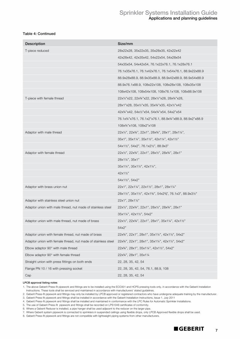
3.5 PipesupportsPipesupportsmustbefixeddirectlytothebuilding
or,ifnecessary,tomachines,storageracksorother
structures.Theymustnotbeusedtosupportanyother
installations.Theymustbeoftheadjustabletypeinorder
tosecureanevenload-bearingcapability.Supportsmust
completelysurroundthepipeandshouldnotbewelded
tothepipeorfittings.
Distributionpipesandrisersmusthaveasuitablenumber
offixedpointstotakeaccountofaxialforces.
Nopartofanysupportmustbemadeofcombustible
material.Nailsmustnotbeused.
Nospecialpipesupportbracketsarerequiredforthe
GeberitMapresspressfittingsystem.Anyappropriately
sizedcommerciallyavailablebracketscanbeused.For
maximumGeberitMapressbracketspacingdistances,
seeTable6.
Table6:Bracketdistancesinaccordance
withLPCBapproval
3.6 Calculationofpressurelossesinpipework
Frictionalpressurelossinpipesshallbefullyhydraulically
calculated.TheHazen-Williamsformulashouldbeused:
Where:
p-isthepressurelossinthepipe,inbar;
Q-istheflowthroughthepipe,inlitresperminute;
d-isthemeaninternaldiameterofthepipe,inmillimetres;
C-isaconstantforthetypeandconditionofthepipe;
L-istheequivalentlengthofpipeandfittings,inmetres.
ThevaluesofCtobeusedinsprinklerinstallationfor
GeberitMapressare:
StainlessSteel-140
CarbonSteel-120
Thedistancefromanyterminalsprinklertoasupport
shallnotexceed:
• 0.9mforDN25diameterpiping
• 1.2mforpipingexceedingDN25diameter.
Thedistanceforanyuprightsprinklertoasupportshall
notbelessthan0.15m.
Verticalpipesshallhaveadditionalsupportsinthe
followingcases:
• Pipesmorethan2mlong
• Pipesmorethan1mlongfeedingsinglesprinklers.
10
p=6.05x10⁵
C1.85xd4.87LQ1.85
Pipedimension Bracketdistance
DN Øxs(mm) (m)
20 22x1.2 2.5
25 28x1.2 2.5
32 35x1.5 2.5
40 42x1.5 3
50 54x1.5 3
65 76.1x2.0 3
80 88.9x2.0 3
100 108x2.0 3.5

SprinklerSystemsInstallationGuideApplicationsandplanningguidelines
3.6.1 Equivalentpipelengths
11
Table7:Equivalentpipelength–MapressØ12-22mm
(continuedoverleaf)
Designation DimensionsØxs(mm) 12x1.0 15x1.0 18x1.0 22x1.0
Bend90° 0.7 0.267 0.370 0.479 0.630
Elbowadaptor90° 1.5 0.572 0.793 1.026 1.351
Pipebridge 0.5 0.191 0.264 0.342 0.450
Bend45° 0.5 0.191 0.264 0.342 0.450
Reducer 0.2 — 0.106 0.137 0.180
Sleeve/Adaptor 0.1 0.038 0.053 0.068 0.090
T-piece(flowseparation) 1.3 0.496 0.688 0.889 1.171
T-piece(flowintegration) 0.9 0.343 0.476 0.616 0.811
T-piece(through-flow) 0.3 0.114 0.159 0.205 0.270
V
V
V
V
V
V
V
V
V
V
V
V
V
V
V
V
V
V
V
V
V
V
V
V
V
V
V
V
V
V
V
V
V
V
V
V
V
V
V
V
V
V
V
V
V
V
V
V
V
V
V
V
V
V
V
V
V
V
V
V
V
V
V
V
V
V
V
V
V
V
V
V
V
V
V
V
V
V
V
V
V
V
V
V
V
V
V
V
V
V
Pressfitting LossCoefficient

SprinklerSystemsInstallationGuideApplicationsandplanningguidelines
12
Table7:Continued
Designation DimensionsØxs(mm) 12x1.0 15x1.0 18x1.0 22x1.0
T-piece(through-flow 0.2 0.076 0.106 0.137 0.180forflowseparation)
T-piece(counterflow 3.0 1.145 1.587 2.052 2.702forflowintegration)
T-piece(counterflow 1.5 0.572 0.793 1.026 1.351forflowseparation)
Cross-piece30° 0.2 — — 0.137 0.180(through-flow)
Pipecross30° 1.3 — — 0.889 1.171(flowseparation)
Pipecross30° 0.9 — — 0.616 0.811(flowintegration)
Pipecross90° 0.2 — 0.106 0.137 0.180(through-flow)
Pipecross90° 1.7 — 0.899 1.163 1.531(flowseparation)
Pipecross90° 1.3 — 0.688 0.889 1.171(flowintegration)
V
V
V
V
V
V
V
V
V
V
V
V
V
V
V
V
V
V
V
V
V
V
V
V
V
V
V
V
V
V
V
V
V
V
V
V
V
V
V
V
V
V
V
V
V
V
V
V
V
V
V
V
V
V
V
V
V
V
V
V
V
V
V
V
V
V
V
V
V
V
V
V
V
V
V
V
V
V
V
V
V
V
V
V
V
V
V
V
V
V
Pressfitting LossCoefficient

SprinklerSystemsInstallationGuideApplicationsandplanningguidelines
13
Table8:Equivalentpipelength–MapressØ28-54mm
Designation DimensionsØxs(mm) 28x1.5 35x1.5 42x1.5 54x1.5
Bend90° 0.7 0.829 1.121 1.427 1.975
Elbowadaptor90° 1.5 1.777 2.403 3.057 4.232
Pipebridge 0.5 0.592 — — —
Bend45° 0.5 0.592 0.801 1.019 1.411
Reducer 0.2 0.237 0.320 0.408 0.564
Sleeve/Adaptor 0.1 0.118 0.160 0.204 0.282
T-piece 1.3 1.540 2.082 2.649 3.668(flowseparation)
T-piece 0.9 1.066 1.442 1.834 2.539(flowintegration)
T-piece(through-flow 0.3 0.355 0.481 0.611 0.846forflowintegration)
T-piece(through-flow 0.2 0.237 0.320 0.408 0.564forflowseparation)
T-piece(counterflow 3.0 3.553 4.805 6.114 8.465forflowintegration)
T-piece(counterflow 1.5 1.777 2.403 3.057 4.232forflowseparation)
LossCoefficient
54
V
V
V
V
V
V
54
V
V
V
V
V
V
54
V
V
V
V
V
V
54
V
V
V
V
V
V
54
V
V
V
V
V
V
54
V
V
V
V
V
V
54
V
V
V
V
V
V
54
V
V
V
V
V
V
54
V
V
V
V
V
V
54
V
V
V
V
V
V
54
V
V
V
V
V
V
54
V
V
V
V
V
V
Pressfitting
SprinklerSystemsInstallationGuideApplicationsandplanningguidelines
14
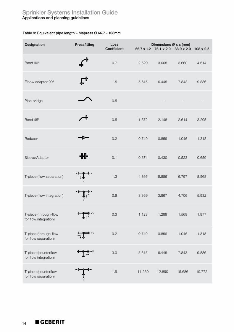
Table9:Equivalentpipelength–MapressØ66.7-108mm
Designation DimensionsØxs(mm) 66.7x1.2 76.1x2.0 88.9x2.0 108x2.5
Bend90° 0.7 2.620 3.008 3.660 4.614
Elbowadaptor90° 1.5 5.615 6.445 7.843 9.886
Pipebridge 0.5 — — — —
Bend45° 0.5 1.872 2.148 2.614 3.295
Reducer 0.2 0.749 0.859 1.046 1.318
Sleeve/Adaptor 0.1 0.374 0.430 0.523 0.659
T-piece(flowseparation) 1.3 4.866 5.586 6.797 8.568
T-piece(flowintegration) 0.9 3.369 3.867 4.706 5.932
T-piece(through-flow 0.3 1.123 1.289 1.569 1.977forflowintegration)
T-piece(through-flow 0.2 0.749 0.859 1.046 1.318forflowseparation)
T-piece(counterflow 3.0 5.615 6.445 7.843 9.886forflowintegration)
T-piece(counterflow 1.5 11.230 12.890 15.686 19.772forflowseparation)
LossCoefficient
Pressfitting
54
V
V
V
V
V
V
54
V
V
V
V
V
V
54
V
V
V
V
V
V
54
V
V
V
V
V
V
54
V
V
V
V
V
V
54
V
V
V
V
V
V
54
V
V
V
V
V
V
54
V
V
V
V
V
V
54
V
V
V
V
V
V
54
V
V
V
V
V
V
54
V
V
V
V
V
V
54
V
V
V
V
V
V

SprinklerSystemsInstallationGuideApplicationsandplanningguidelines
15
3.7 ExpansioncompensationPipesexpanddifferentlyduetothermaleffects
dependingontheproductmaterial.Thisshouldbe
consideredwhen:
• Creatingexpansionspace
• Installingexpansioncompensations
• Positioningfixedpointsandslidingpoints
Thebendingandtorsionalstressoccurringduring
theoperationofapipearereliablyabsorbed,takingthe
expansioncompensationintoaccount.
Thefollowingaffecttheexpansioncompensation:
• Material
• Buildingconditions
• Operatingconditions.
Slightchangesinthelengthofpipescanbe
accommodatedbytheelasticityofthepipenetwork.
Expansioncompensatorsusedare:
• Pipeleg
• Ubend.
Thefollowingshowtheprincipleassemblyofthepipeleg
andUbend.
Figure 4: Expansion compensation by pipe leg
BS: Bendingleg
F: Fixedpoint
GL: Slidingpoint
L: Pipelength
L1BS2
GLGLF GL
GL
F
L2
BS1
Figure 5: Expansion compensation by U bends
BS: Bendingleg
F: Fixedpoint
L: Pipelength
L1 L2
BSF F
SprinklerSystemsInstallationGuideApplicationsandplanningguidelines
16
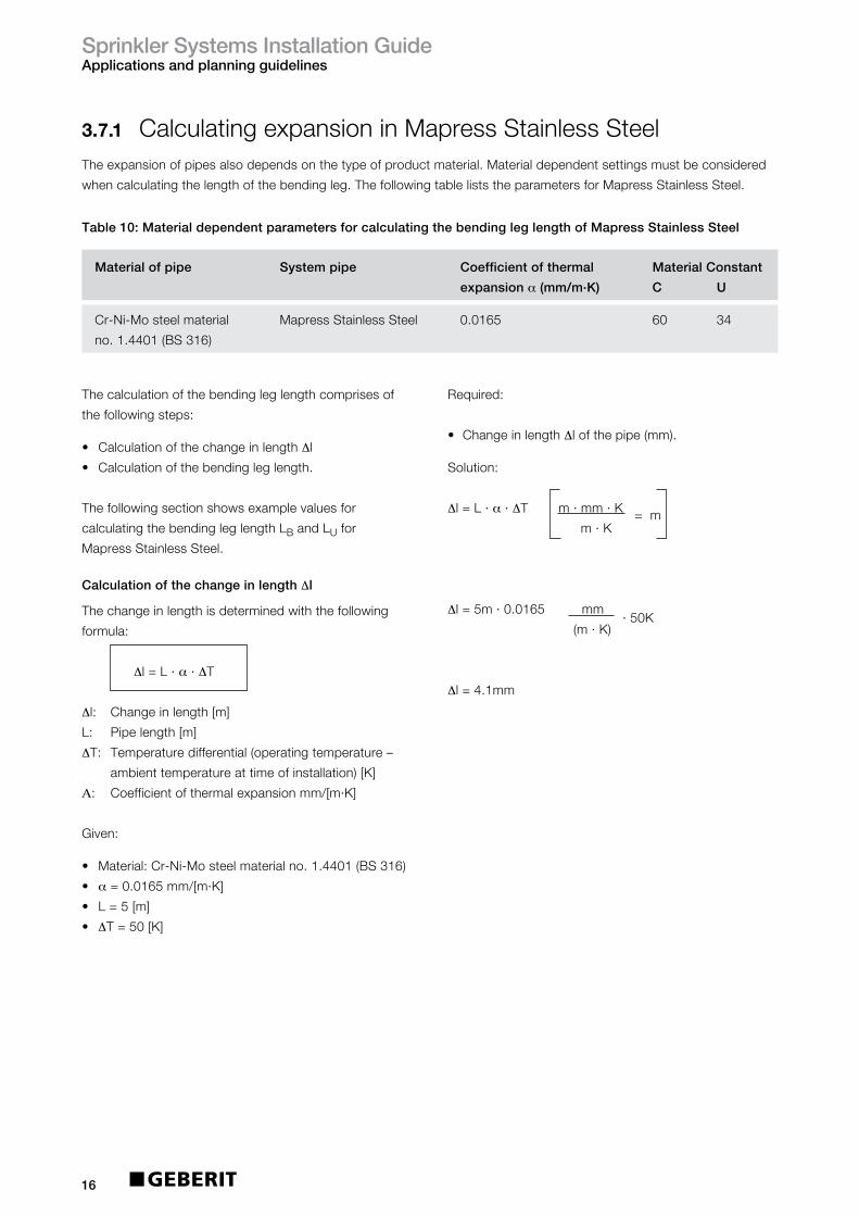
Materialofpipe Systempipe Coefficientofthermal MaterialConstant
expansionα(mm/m.K) C U
Cr-Ni-Mosteelmaterial MapressStainlessSteel 0.0165 60 34
no.1.4401(BS316)
Table10:MaterialdependentparametersforcalculatingthebendingleglengthofMapressStainlessSteel
3.7.1 CalculatingexpansioninMapressStainlessSteelTheexpansionofpipesalsodependsonthetypeofproductmaterial.Materialdependentsettingsmustbeconsidered
whencalculatingthelengthofthebendingleg.ThefollowingtableliststheparametersforMapressStainlessSteel.
Required:
• ChangeinlengthΔlofthepipe(mm).
Solution:
Δl=L·α·ΔTm·mm·K=m m·K
Δl=5m·0.0165mm·50K
(m·K)
Δl=4.1mm
Thecalculationofthebendingleglengthcomprisesof
thefollowingsteps:
• CalculationofthechangeinlengthΔl
• Calculationofthebendingleglength.
Thefollowingsectionshowsexamplevaluesfor
calculatingthebendingleglengthLBandLUfor
MapressStainlessSteel.
CalculationofthechangeinlengthΔl
Thechangeinlengthisdeterminedwiththefollowing
formula:
Δl=L·α·ΔT
Δl: Changeinlength[m]
L: Pipelength[m]
ΔT: Temperaturedifferential(operatingtemperature–
ambienttemperatureattimeofinstallation)[K]
Α: Coefficientofthermalexpansionmm/[m·K]
Given:
• Material:Cr-Ni-Mosteelmaterialno.1.4401(BS316)
• α=0.0165mm/[m·K]
• L=5[m]
• ΔT=50[K]

SprinklerSystemsInstallationGuideApplicationsandplanningguidelines
17
Calculationofthebendingleglength:StainlessSteel
Thecalculationofthebendingleglengthdependsonthe
typeofbendingleg:
• Expansioncompensationthroughpipeleg/forbranch
pipe:CalculationofthebendingleglengthLB• ExpansioncompensationbyUbends:Calculationof
thebendingleglengthLU
CalculationofthebendingleglengthLB
ThebendingleglengthLWtobecalculatedisdefinedas
followswithexpansioncompensationthroughpipelegs
andforbranchpipes:
Figure 6: Expansion compensation by pipe leg
F: Fixedpoint
GL: Slidingpoint
LB: Lengthofthebendingleg
Figure 7: Expansion compensation for branching pipe
F: Fixedpoint
GL: Slidingpoint
LB: Lengthofthebendingleg
Table11:ChangeinlengthΔl(mm)forMapressStainlessSteelsystempipe
∆I
LB
GL
F
F GL
GL
∆I
∆I
LB
GL
GL
PipelengthTemperaturedifferentialΔT(K)
10 20 30 40 50 60 70 80 90 100
1 0.17 0.33 0.50 0.66 0.83 0.99 1.16 1.32 1.49 1.65
2 0.33 0.66 0.99 1.32 1.65 1.98 2.31 2.64 2.97 3.30
3 0.50 0.99 1.49 1.98 2.48 2.97 3.47 3.96 4.46 4.95
4 0.66 1.32 1.98 2.64 3.30 3.96 4.62 5.28 5.94 6.60
5 0.83 1.65 2.48 3.30 4.13 4.95 5.78 6.60 7.43 8.25
6 0.99 1.98 2.97 3.96 4.95 5.94 6.93 7.92 8.91 9.90
7 1.16 2.31 3.47 4.62 5.78 6.93 8.09 9.24 10.40 11.55
8 1.32 2.64 3.96 5.28 6.60 7.92 9.24 10.56 11.88 13.20
9 1.49 2.97 4.46 5.94 7.43 8.91 10.40 11.88 13.37 14.85
10 1.65 3.30 4.95 6.60 8.25 9.90 11.55 13.20 14.85 16.50
L(m)
SprinklerSystemsInstallationGuideApplicationsandplanningguidelines
18
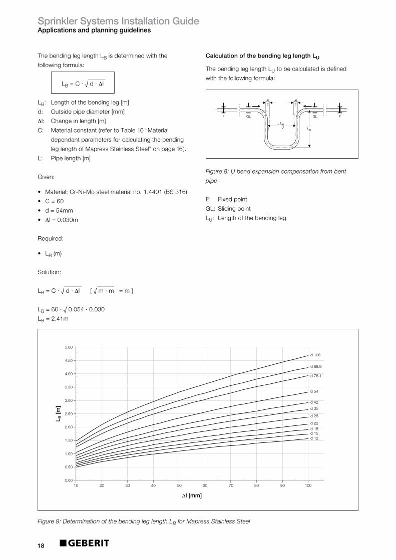
ThebendingleglengthLBisdeterminedwiththe
followingformula:
LB=C·√d·Δl
LB: Lengthofthebendingleg[m]
d: Outsidepipediameter[mm]
Δl: Changeinlength[m]
C: Materialconstant(refertoTable10“Material
dependantparametersforcalculatingthebending
leglengthofMapressStainlessSteel”onpage16).
L: Pipelength[m]
Given:
• Material:Cr-Ni-Mosteelmaterialno.1.4401(BS316)
• C=60
• d=54mm
• Δl=0.030m
Required:
• LB(m)
Solution:
LB=C·√d·Δl[√m·m=m]
LB=60·√0.054·0.030
LB=2.41m
CalculationofthebendingleglengthLU
ThebendingleglengthLUtobecalculatedisdefined
withthefollowingformula:
Figure 8: U bend expansion compensation from bent
pipe
F: Fixedpoint
GL: Slidingpoint
LU: Lengthofthebendingleg
d 22
d 42
d 54
d 76.1
d 88.9
d 108
d 15d 12
d 18
d 28
d 35
0.00
0.50
1.00
1.50
2.00
2.50
3.00
3.50
4.00
4.50
5.00
L B [m
]
20 40 60 80 10010 30 50 70 90
∆I [mm]
Figure 9: Determination of the bending leg length LB for Mapress Stainless Steel
∆I 2
Lu
GL GL
∆I 2
~ Lu 2
F F
SprinklerSystemsInstallationGuideApplicationsandplanningguidelines
19
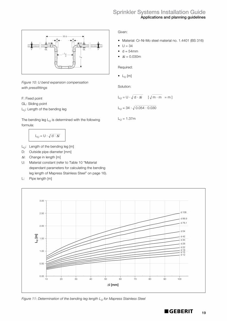
Figure 10: U bend expansion compensation
with pressfittings
F:Fixedpoint
GL:Slidingpoint
LU:Lengthofthebendingleg
ThebendinglegLUisdeterminedwiththefollowing
formula:
LU=U·√d·Δl
LU: Lengthofthebendingleg[m]
D: Outsidepipediameter[mm]
Δl: Changeinlength[m]
U: Materialconstant(refertoTable10“Material
dependantparametersforcalculatingthebending
leglengthofMapressStainlessSteel”onpage16).
L: Pipelength[m]
~ Lu 2
∆I2
Lu
∆I2
30 d
GL GLF F
d 12
d 22
d 42
d 54
d 76.1
d 88.9
d 108
d 15d 18
d 28
d 35
0.00
0.50
1.00
1.50
2.00
2.50
L U [m
]
20 40 60 80 10010 30 50 70 90
∆I [mm]
3 00.
Figure 11: Determination of the bending leg length LU for Mapress Stainless Steel
Given:
• Material:Cr-Ni-Mosteelmaterialno.1.4401(BS316)
• U=34
• d=54mm
• Δl=0.030m
Required:
• LU[m]
Solution:
LU=U·√d·Δl[√m·m=m]
LU=34·√0.054·0.030
LU=1.37m

SprinklerSystemsInstallationGuideApplicationsandplanningguidelines
20
3.7.2 CalculatingexpansioninMapressCarbonSteel
Solution:
Δl=L·α·ΔTm·mm·K=m
m·K
Δl=35m·0.012mm·50K
(m·K)
Δl=21mm
Table12:MaterialdependentparametersforcalculatingthebendingleglengthofMapressCarbonSteel
Theexpansionofpipesalsodepends,amongstothers,onthetypeofproductmaterial.Materialdependent
parametersmustbeconsideredwhencalculatingthelengthofthebendingleg.Thefollowingtableliststheparameters
forMapressCarbonSteel.
Thecalculationofthebendingleglengthcomprisesof
thefollowingsteps:
• CalculationofthechangeinlengthΔl
• CalculationofthebendingleglengthLB
Thefollowingsectionshowsexamplevaluesfor
calculatingthebendingleglengthLWandLUfor
MapressCarbonSteel.
CalculationofthechangeinlengthΔl
Thechangeinlengthisdeterminedwiththefollowing
formula:
Δl=L·α·ΔT
Δl: Changeinlength[m]
L: Pipelength[m]
ΔT: Temperaturedifferential(operatingtemperature–
ambienttemperatureattimeofinstallation)[K]
α: Coefficientofthermalexpansionmm/[m·K]
Given:
• Material:Non-alloysteelmaterialno.1.0034
• α=0.0120m/[m·K]
• L=35[m]
• ΔT=50[K]
Required:
• ChangeinlengthΔlofthepipe[mm]
Materialofpipe Systempipe Coefficientofthermal MaterialConstant
expansionα(mm/m.K) C U
Non-alloysteel, MapressCarbonSteel 0.012 4525
materialno.1.0215

SprinklerSystemsInstallationGuideApplicationsandplanningguidelines
21
Calculationofthebendingleglength:CarbonSteel
Thecalculationofthebendingleglengthdependsonthe
typeofbendingleg:
• Expansioncompensationthroughpipeleg/forbranch
pipe:CalculationofthebendingleglengthLB• ExpansioncompensationbyUbends:Calculationof
thebendingleglengthLU
CalculationofthebendingleglengthLB
ThebendingleglengthLBtobecalculatedisdefinedas
followswithexpansioncompensationthroughpipelegs
andforbranchpipes:
Figure12:Expansioncompensationbypipeleg
F: Fixedpoint
GL: Slidingpoint
LB: Lengthofthebendingleg
Figure13:Expansioncompensationforbranchingpipe
F: Fixedpoint
GL: Slidingpoint
LB: Lengthofthebendingleg
PipelengthTemperaturedifferentialΔT(K)
10 20 30 40 50 60 70 80 90 100
1 0.12 0.24 0.36 0.48 0.60 0.72 0.84 0.96 1.08 1.20
2 0.24 0.48 0.72 0.96 1.20 1.44 1.68 1.92 2.16 2.40
3 0.36 0.72 1.08 1.44 1.80 2.16 2.52 2.88 3.24 3.60
4 0.48 0.96 1.44 1.92 2.40 2.88 3.36 3.84 4.32 4.80
5 0.60 1.20 1.80 2.40 3.00 3.60 4.20 4.80 5.40 6.00
6 0.72 1.44 2.16 2.88 3.60 4.32 5.04 5.76 6.48 7.20
7 0.84 1.68 2.52 3.36 4.20 5.04 5.88 6.72 7.56 8.40
8 0.96 1.92 2.88 3.84 4.80 5.76 6.72 7.68 8.64 9.60
9 1.08 2.16 3.24 4.32 5.40 6.48 7.56 8.64 9.72 10.80
10 1.20 2.40 3.60 4.80 6.00 7.20 8.40 9.60 10.80 12.00
Table13:ChangeinlengthΔl(mm)forMapressCarbonSteelsystempipe
∆I
LB
GL
F
F GL
GL
∆I
∆I
LB
GL
GL
L(m)

SprinklerSystemsInstallationGuideApplicationsandplanningguidelines
22
ThebendingleglengthLBisdeterminedwiththe
followingformula:
LB=C·√d·Δl
LB: Lengthofthebendingleg[m]
d: Outsidepipediameter[mm]
Δl: Changeinlength[m]
C: Materialconstant(refertoTable12“Material
dependentparametersforcalculatingthebending
leglengthofMapressCarbonSteel”onpage20).
L: Pipelength[m]
Given:
• Material:Non-alloysteelmaterialno.1.0034
• C=45
• d=54[mm]
• Δl=0.021[m]
Required:
• LB[m]
Solution:
LB=C·√d·Δl[√m·m=m]
LB=45·√0.054·0.021
LB=1.52m
CalculationofthebendingleglengthLU
ThebendingleglengthLUtobecalculatedisdefined
withthefollowingformula:
Figure 14: U bend expansion compensation
from bent pipe
F: Fixedpoint
GL: Slidingpoint
LU: Lengthofthebendingleg
20 40 60 80 10010 30 50 70 90
∆I [mm]
d 12
d 22
d 42
d 54
d 76.1
d 88.9
d 108
d 15d 18
d 28
d 35
L B [m
]
0.00
0.50
1.00
1.50
2.00
2.50
3.00
3.50
4.00
4.50
5.00
Figure 15: Determination of the bending leg length LB for Mapress Carbon Steel
∆I 2
Lu
GL GL
∆I 2
~ Lu 2
F F

SprinklerSystemsInstallationGuideApplicationsandplanningguidelines
23
Figure 16: U bend expansion compensation with
pressfittings
F: Fixedpoint
GL: Slidingpoint
LU: Lengthofthebendingleg
ThebendinglegLUisdeterminedwiththefollowing
formula:
LU=U·√d·Δl
LU: Lengthofthebendingleg(m)
D: Outsidepipediameter(mm)
Δl: Changeinlength(m)
U: Materialconstant(refertoTable12“Material
dependantparametersforcalculatingthebending
leglengthofMapressCarbonSteel”onpage20).
L: Pipelength(m)
~ Lu 2
∆I2
Lu
∆I2
30 d
GL GLF F
d 12
d 22
d 42
d 54
d 76.1
d 88.9
d 108
d 15d 18
d 28
d 35
0.00
0.50
1.00
1.50
2.00
2.50
L U [m
]
20 40 60 80 10010 30 50 70 90
∆I [mm]
3 00.
Figure 17: Determination of the bending leg length LU for Mapress Carbon Steel
Given:
• Material:Non-alloysteelmaterialno.1.0034
• U=25
• d=54mm
• Δl=0.021m
Required:
• LU(m)
Solution:
LU=U·√d·Δl[√m·m=m]
LU=34·√0.054·0.021
LU=0.84m
SprinklerSystemsInstallationGuideApplicationsandplanningguidelines
24
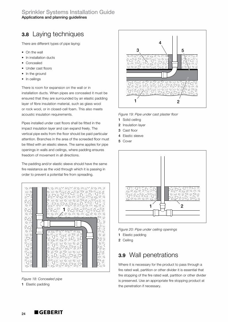
3.8 LayingtechniquesTherearedifferenttypesofpipelaying:
• Onthewall
• Ininstallationducts
• Concealed
• Undercastfloors
• Intheground
• Inceilings
Thereisroomforexpansiononthewallorin
installationducts.Whenpipesareconcealeditmustbe
ensuredthattheyaresurroundedbyanelasticpadding
layeroffibreinsulationmaterial,suchasglasswool
orrockwool,orinclosed-cellfoam.Thisalsomeets
acousticinsulationrequirements.
Pipesinstalledundercastfloorsshallbefittedinthe
impactinsulationlayerandcanexpandfreely.The
verticalpipeexitsfromthefloorshouldbepaidparticular
attention.Branchesintheareaofthescreededfloormust
befittedwithanelasticsleeve.Thesameappliesforpipe
openingsinwallsandceilings,wherepaddingensures
freedomofmovementinalldirections.
Thepaddingand/orelasticsleeveshouldhavethesame
fireresistanceasthevoidthroughwhichitispassingin
ordertopreventapotentialfirefromspreading.
3.9 WallpenetrationsWhereitisnecessaryfortheproducttopassthrougha
fireratedwall,partitionorotherdivideritisessentialthat
firestoppingofthefireratedwall,partitionorotherdivider
ispreserved.Useanappropriatefirestoppingproductat
thepenetrationifnecessary.
1
Figure 18: Concealed pipe
1 Elasticpadding
Figure 19: Pipe under cast plaster floor
1 Solidceiling
2 Insulationlayer
3 Castfloor
4 Elasticsleeve
5 Cover
Figure 20: Pipe under ceiling openings
1 Elasticpadding
2 Ceiling
4
3 5
21
21
21

SprinklerSystemsInstallationGuideInstallation
25
4 Installation
4.1 ToolingThefollowingtoolingcombinationsshouldbeusedforinstallingGeberitMapressforfireprotectionsystems.
4.2 TransportandstorageDonotallowGeberitMapresssystempipesand
pressfittingstogetdirtyordamagedintransitorstorage.
Pipesneedtobestoredinsideinadrylocation.
4.3 MakingaMapress pressconnectionAMapresspressconnectionismadeasfollows:
• Preparethepipeandfittingforthepressingoperation.
• Pushpipeintofittingtocorrectinsertiondepth.
• Optional:WithØ54-108mmfitthemounting
deviceMH1.
• Pressthefitting.
WARNING
Riskofcorrosion
Keepcuttingtoolsanddeburringtoolsfree
fromCarbonSteelchipswhencuttingMapress
StainlessSteel
Donotusehigh-speedcuttingwheelstocut
thepipeorfittingstolength
Onlyusecuttingtoolsthataresuitablefor
workingwithsteel
Leakingpressconnectioncanbecausedby
damagedsealring
Deburrtheoutsideandinsideofthepipeends
completely
Donottiltthepipeintothepressfitting.
Pushthepressfittingontothepipe,turningthe
pipeslightly
Onlyuselubricantswhicharefreefromoil
andgrease
Onlyshortenthefittingswithplainendsupto
themaximumpermissibleshorteningdimensionk,
indicatedintheproductguide.
i
DiametersPressed
22-88.9mm
35/42/54mm=
(ZB302)90668
76.1/88.9mm=
(ZB321)90674
3
3
3
76-108mmHCPS
HCPS
ECO301
ECO301
ECO301
115V/50Hz
230V/50Hz
125v/60Hz
CEE17yellow
BS1363Aplug
MarineNEMAplug
691.312.1P.3
691.310.P5.3
691.312.2P.3
90644(22mm)
90645(28mm)
230V/50Hz
115V/50Hz
BS1363Aplug
CEE17yellow
691.420.P5.1
691.422.1P.1HCPS n/a n/a
35mm=90538
42mm=90539
54mm=90540
76.1mm-=90671
88.9mm=90672
Model Voltage Plugtype ArticleNo.Jawstype
compatability
PressingJaw
(Sizemm)Adaptor
PressingCollar
(Sizemm)
Table14:SuitabletoolingcombinationsforGeberitMapressandFireProtectionsystems
76.1mm=90570
88.9mm=90571
108mm=90572
SprinklerSystemsInstallationGuideInstallation
26
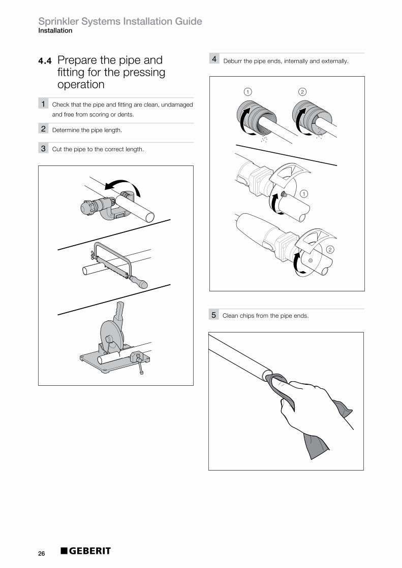
4.4 Preparethepipeand fittingforthepressing operation
1
2
Checkthatthepipeandfittingareclean,undamaged
andfreefromscoringordents.
Determinethepipelength.
3 Cutthepipetothecorrectlength.
1 2
1
2
4 Deburrthepipeends,internallyandexternally.
5 Cleanchipsfromthepipeends.

SprinklerSystemsInstallationGuideInstallation
27
di
E
6a Marktheinsertiondistance.
Insufficientmechanicalstrengthifcorrect
insertion(E)isnotobserved.i
distance
6b Onfittingswithaplainend,marktheinsertion
distanceontheend.
1
2
7 Removetheplugfromthefitting.
di
8 Checkthesealring.

SprinklerSystemsInstallationGuideInstallation
28
E
E
CAUTION
Leakingconnectionduetostress
corrosioncracking.Donotuse
Teflonforsealing
Maketheconnectionwiththethreadedfitting
9 Pushthefittingontothepipeuptothemarked
insertiondistance.
10 Alignthepipe.
Fixthepipeinposition.
Sealinthethreadedconnection.
Insertthethreadedfittingandscrewintoplace,
counterholdingthethreadedfitting.
123
Thefittingcanbepushedinmoreeasilyifoil
andgrease-freelubricantisappliedorthefitting
isimmersedinwaterorsoapywater.
iTheinstallationdimensionsaregiveninthe
operatinginstructionsofthemountingaid.i
Optional:withØ54-108mmfitthemountingaidMH1
• Clampthepipeswiththejawsofthemountingaid.
Pressthefitting
Prerequisites
• Thepipeorpre-assembledelementsarealigned
• Threadedjointsmustbesealedin.
Ensurethatthediameterofthepressfittingmatches
thediameterofthepressingjaworpressingcollar:
Ø12-35mmusepressingjaw,Ø42-108mmuse
pressingcollarandadaptor.
Pressthefitting.
1
2

SprinklerSystemsInstallationGuideInstallation
29
Result
•Themarkoftheinsertiondistanceisvisible.

SprinklerSystemsInstallationGuideCommissioning
30
5 Commissioning
5.1 BendingthesystempipesGeberitMapresssystempipescanbecoldbent.Todo
so,usecommerciallyavailablebendingtools(manually,
hydraulicallyorelectricallyoperated).Itisimportantto
alwaysusethebendingsegmentsfortheparticularouter
diameterofthesystempipes.Thebendingradiusand
thesuitabilityofthebendingtoolisdeterminedbythe
manufacturerofthetool.GeberitMapressrecommends
usingabendingradiusofr=3.5xOD.
5.2 Connections• ConnectingtosprinklerheadsandISO65pipework
InordertoconnectGeberitMapresstoalternative
pipingsystems,accessoriesandsprinklerheads,
threadedadaptorsareavailableundertheLPCBlisting
ofapprovedproducts.
• Threadedjoints
GeberitMapresscomponentscanbecombinedwith
threadedfittingsorsystempipesmadeofnon-ferrous
metal.WhenGeberitMapressStainlessSteeladaptors
areused,onlychloride-freesealantsmaybeemployed.
• Flangeconnections
GeberitMapresscomponentscanbeconnectedto
DINflanges[PN10/16]withflangedadaptors(see
GeberitSupplySystemsProductGuide)
5.3 FlushingthepipesAllmetallicpipingsystemsareatahighriskofcorrosion
whentheyarepartiallyfilled.Werecommendthatthe
pipeisflushedthoroughlypriortocommissioningusing
drinkingwater.
Ifthepipecannotbecompletelydrainedbefore
commissioningandifthepipecannotbeblowndrywith
airafterflushing,thepipemustbeflushedwithfully
desalinatedwater.
5.4 PressureandleaktestAllinstallationpipeworkshallbehydostaticallytestedfor
nolessthan2hours,toapressureofnolessthan15bar,
or1.5timesthemaximumpressuretowhichthesystem
willbesubjected,(bothmeasuredattheinstallation
controlvalves),whicheveristhegreater.
Aninitialtestwithaircanbeperformedifthereistobea
gapbetweenthetestingandcommissioningphase.
Forsafetyreasons,thepressureforthistestshouldnever
exceed3bar.Asecondtestwithwatershouldalwaysbe
carriedoutimmediatelypriortocommissioning.
5.5 Refillingandair-bleeding ofthepipesystemfor commissioningIfthepipesystemwasdrainedcompletelyafter
pressuretesting,thewater-carryingpipesmustbe
thoroughlyair-bledbeforecommissioningandthen
remaincompletelyfull.Thewaterusedtofillthepipes
mustcomplywiththedrinkingwaterdirective2001,
withregardtoitschloridecontent.
5.6 CompatibilityofadditivesWateradditivesaremainlyusedforprovidinganti-freeze
propertiesforwetsprinklersystemsduringthewinter
season.Commonlyusedaremixturesbasedon
anti-freezeagents(ethylene-orpropyleneglycol)in
combinationwithcorrosioninhibitors.Theglycolswill
alwayshaveaninfluenceonthezinclayerontheinsideof
thepipingsystemandcanthereforenotberecommended
foruseinconjunctionwithGeberitMapressCarbonSteel
internally/externallygalvanisedpipe.
GeberitMapressissuitablefortraceheatinginareas
wherelowtemperaturescan’tbeavoided
ForafulllistofcompatibleadditivesforusewithGeberit
MapressStainlessSteelpleaseseeTables15&16.

SprinklerSystemsInstallationGuideCommissioning
31
5.7 Compatiblepaints andcoatingsPrimersandpaintscanbeappliedonMapressCarbon
SteelandMapressStainlessSteelsystems.Fromlongterm
experiencewecanconfirmthattheprimersandpaintswill
havenonegativeeffectonthesealringsinthepressfittings.
5.8 MaintenanceAsprinklersystemshouldberegularlyserviced,maintained
andperiodicallyinspectedsothatitwillworkproperlyinthe
eventofafire.Sprinklersystemshaveanextensiveservice,
maintenanceandinspectionprogrammecoveringthewhole
oftheirdesignlife,includingweekly,monthly,quarterly,
yearly,three-yearly,uptoten-yearlychecksandtests.
Regularserviceandmaintenanceshouldbecarriedoutin
accordancewiththeLPCRules(BSEN12845annexK)
andTechnicalBulletinTB203,byaLPCBcertifiedsprinkler
contractor,forallbutthemonthlyandweeklychecks.
5.9 ServicelifeAnexpectedservicelifeinexcessof30yearscanbe
achieved.
Table15:SuitableantifreezeagentsforGeberitMapressStainlessSteel
ApprovalmustbeobtainedfromGeberitfornon-listedagents.Themanufacturer’sinstructions
forusemustalsobeobserved.
Additive TestConditions Manufacturer1
Concentration(%)
Ethyleneglycol(antifreezebasis) Concentrationforuse,seemanufacturer’sinformation Variousmanufacturers
Propyleneglycol(antifreezebasis) Concentrationforuse,seemanufacturer’sinformation Variousmanufacturers
Table16:TestedandapprovedcorrosionprotectionagentsforGeberitMapressStainlessSteel
Additive TestConditions Manufacturer1
Concentration(%) Temperature(ºC)
CastrolZwiproIII 100 20 Castrol
DiaglossCW4001 3.5 40 SchweitzerChemie,Freiberg/N.
DEWT-NC 0.4 20 DrewAmeroid,Hamburg
Hydrazine Concentrationforuse,seemanufacturer’sinformation Lanxess,Leverkusen
Levoxin64 100 120 Lanxess,Leverkusen
HygelH140 100 20 HydrogelChemie,Werl
Kebocor213 0.5 20 KeboChemie,Düsseldorf
Nalco77382 0.5 20 NalcoDeutschlandGmbH
Sodium 0.07 20 Variousmanufacturersdiethyldithiocarbamate
Sodiumsulphite Concentrationforuse,seemanufacturer’sinformation Variousmanufacturers
P3-ferrolix332 0.5 20 HenkelAG,Düsseldorf
ST-DOSK-375 0.5 20 SchweitzerChemie,Freiberg/N.
ThermodusJTH-L 1 90 Judo,Waiblingen
Tri-sodiumphosphate Concentrationforuse,seemanufacturer’sinformation Variousmanufacturers
VaridosSIS 100 20 SchillingChemie,Freiberg
SprinklerSystemsInstallationGuideSupportServices
32
6 SupportservicesGeberitnotonlyfocusesonreliableandinnovative
productsbutontheservicesthataccompanythem.
Whilstwehopethisguideprovidesyouwitheverything
youneedtoinstallaGeberitfireprotectionsystem,further
assistanceisavailableasoutlinedbelow.Furtherliterature
isalsoavailable,includingtheGeberitSupplySystems
ProductGuideandSupplySystemsInstallationguide,
bycallingourliteraturelineon08000075133orby
downloadingfromourwebsiteatwww.geberit.co.uk
6.1 GeberittechnicalserviceOurteamofdedicatedtechnicalexpertsandsales
managersareonhandtosupportbothatthedesign
stageandon-site.PleasecontacttheGeberittechnical
teamforassistance.
GeberitSalesLtd,
GeberitHouse,
AcademyDrive,
Warwick,
Warwickshire,
CV346QZ.
Freephone:08000778365
Fax:08448006604
Eire:+44(0)1926516800
6.2 TrainingGeberitprovidefullproducttraining,eitheron-siteorat
theGeberitAcademyatourheadquartersinWarwick.
Pleasecontactyourlocalsalesmanagerformoredetails.