Embed Size (px)
Citation preview
ELSEVIER
Electrical Power & Energy Systems, Vol. 20, No. 6, pp. 421-425, 1998 © 1998 Elsevier Science Ltd. All rights reserved
Printed in Great Britain PII: S0142-0615(97)00048-3 0142-0615/98/$19.0o+0.00
A pole sensitivity method for analyzing harmonic magnification in a power system
Liyi Chen a'* and Wenyi Li b aDepartment of Electrical Power and Automation Engineering, Tianjin University, Tianjin 300072, People's Republic of China bDepartment of Electrical Power Engineering, Inner Mongolia Electric Power Institute, Huhehaote, People's Republic of China
Harmonic resonance caused by the compensation capacitor banks in electric power systems is discussed in this paper. A method used to s t u ~ the harmonic resonance and the harmonic magnification is presented. In this method, the calculation of system poles is combined with the calculation of pole sensitivities respective to the system's branch parameters. As a result, the information referring to the power system's harmonic resonance, the harmonic current magnification and the harmonic suppression strategy can be obtained by usfiag this method. © 1998 Elsevier Science Ltd. All rights reserved.
Keywords: Power system, Harmonic resonance, Harmonic current magnification, Pole sensitivity
I. Introduction The voltage and the current of an electrical power system are generally considered as sinusoidal. However, when some of nonEnear elements such as solid-state electronic power inverters and arc welding devices are applied to the power systems the waveform of voltage and current are seriously distorted. Hence, the nonlinear elements become harmonic sources in the power system, which will harm certain types of electrical equipment; for example, the harmonic resonance in reactive compensation capacitor banks installed at substations. During the harmonic resonance period, the harmonic current of the compensation capacitor banks will increase dramatically, which, in turn, will damage equipment or shorten its life [1]. In order to determine the impact of harmonic current magnification on
Received 12 July 1996; accepted 15 May 1997 * Corresponding author, E-maih [email protected]
power systems, the cause of system resonance must be studied and the harmonic current flowing into every branch must be calculated.
The analysis of power system harmonic resonance by using the input-output method, which is based on the frequency search, has been reported [4]. The purpose of this paper is to report the study of the harmonic resonance and the harmonic current magnification by additionally applying a method based on examining all system poles and their sensitivity to the parameters of system branches [2,3]. The advantage of this combinative method is that not only can the question of whether the harmonic resonance occurs in a power system be determined, but also the system elements on which the resonance occurs and the distribution of harmonic current can be calculated. Thus, the effective way to suppress harmonic magnification can be found.
II. Ne twork state equations Since a power system network consists of voltage sources E, current sources i, transmission lines, transformers, capacitors and reactors, it can be represented by an RLC (resistance-inductance-capacitance) circuit. During investi- gation of the harmonic resonance of a power system, these assumptions are taken: (a) shunt capacitance, resistance of a transmission line, and the resistance of reactor are negligi- ble; (b) the load is negligible because it has no influence on the harmonic resonance; and (c) a harmonic source can be considered as a single current source. The network state equations and the output equations are given as follows:
X = A X + b i (1)
u = DX (2)
421
422 Analyzing harmonic magnification: Liyi Chen and Wenyi Li
where
I: ttl ]0 X = [Uct lc] ; A = lg
b = [ 0 " " 0 C ic 1 0 " " 0 ] ;
i H X /'/ct ilc Ctt, Ccc
Ltt, Lee
Cic
Qcl
Q ,
D = [0""0 1 0" ' 0 ] ; g = QcT; h = - Qcl;
L = Lcc + Q~lLttQll
with the following nomenclature,
harmonic current sources harmonic voltage sources n-dimensional state variables voltages of capacitance tree branches currents of inductance link branches tree branch capacitance and link branch capacitance tree branch inductance and link branch inductance link branch capacitance of injected harmonic current sources submatrix consisted of tree branch capacitance and link branch inductance submatrix consisted of tree branch inductance and link branch inductance
where A is the matrix of the network state equation; Si is the ith eigenvector of A; and Xi is the ith eigenvalue (pole) of A.
Denoting the transpose of A as A T and the eigenvalue as h~. Then:
A T v / = )kiV i (8)
where V~ is the ith eigenvector of A T. Since A, X and S are related to the branch parameter c~ of
the system, one can write:
(OA/Oa)Si + A(OSi/Ocx) = ki(OSi/Oa) + (Ok/Oa)S~ (9)
and
[ OA[Oa)Si] T V i -.[- [A(OSi/Oot)] T V i
= ~ki[OSi/Ool]Tvi q- (O~OoL)sTv i (10)
According to equation (8), the second term on left-hand in equation (10) becomes:
[ OSi[o~]T A T V i = k i [ OSi[Ool] T V i (11 )
Therefore, equation (10) can be written as the following:
[ ( O A/OoOSi] T Vi = ( axi/ooOsT vi (12)
Finally, the desired sensitivity of Xi to c~ is given as:
ax,/a = { [ ( aA/aot)si]T vi } / (s T vi) (13)
Taking the Laplace transform of equation (1), one can have:
X = (SI - A) - ~bi = [adj(SI - A ) / d e t ( S I - A)]bi (3)
where adj(Sl - A) is the adjoint matrix of (SI - A). From equations (2) and (3), one obtains:
u = D[ad j (S l - A ) / d e t ( S I - A)]bi (4)
and
Z(S ) = u/i = D[adj (S I - A ) / d e t ( S I - A)]b (5)
Substituting D and b in equation (5), the impedance Z(s ) can be expressed as:
Z(s ) = det(Sl - Aic)/[Cic det(SI - A)] (6)
where adj(Sl - A) is the complement of det(SI - A). From equation (6), one can see that the eigenvalues of the
matrix A correspond to the poles of Z(s), which are the harmonic order of the inherent current resonance of a system. Therefore, when the harmonic order of the injected harmonic source is close to the eigenvalue of the matrix A, the current resonance will occur in the power system. The eigenvalues of the matrix A can be calculated by means of the QR matrix transformation method.
III. Sensitivity of the eigenvalues to the system branch parameters Analyzing the sensitivity of the poles to branch parameters is an effective method to detect locations where the harmonic reso- nance seriously occurs. In order to evaluate a method of elim- inating harmonic resonance, two steps of calculation are needed.
III. 1 Calculation of the sensitivity of poles to the branch parameters The general form of an eigenvalue problem can be written in the matrix form:
A S i = )kiS i (7)
111.2 Calculation of the eigenvector Si In order to obtain the sensitivity 0k/&x, the eigenvectors S i and Vi are calculated by using the inverse iteration method [5]. The general expression of successive approximations are presented as:
( A - - k i I ) W k + l = S k ; k = 0 , 1, 2 , " " (14)
S k + l = W k + l / m a x ( l W k + l l ) j ; k = 0 , 1, 2, . . . (15) l<_j<_n
where S~+1 is the approximation of S; k i is the ith eigenvalue; Wk+] is the approximation of the middle vector W in the (k + 1)th iteration. The results of the eigenvetor Sk+l, can be obtained by repeatedly executing the iteration process until S~+l is sufficiently close to S~. If )k i is a complex, let )k i =OL i + j ~ , S = Q + j R , W = M + j N , equations (14) and (15) become:
[ ( A - - 0¢ii) 2 "J¢- t32i I]Nk + 1
= 13iQ k + (A - aiI)Rk; k = 1, 2 , " " (16)
(A - otil)Nk+ ] -- 13ilMk+ 1 = Rk ; k = 1, 2,--- (17)
Qk+,=Mk+,/maxn(JMk+ll)j; k = l , 2,. . . (18)
Rk+l = N k + l / max (INk+ll)j; k = 1, 2,--. (19) 1 <-j<--n
The eigenvector Vi of A T can be obtained by using the same method.
IV. Calculation of the harmonic magnification From the calculation processes shown above, one can obtain eigenvalues that are close to the order of harmonic sources and the maximum sensitivity of ki, respect to a. Assume this maximum sensitivity occurs when a = otj. Obviously, thejth branch parameter c~j has the most significant affect on the
Analyzing harmonic magnification: Liyi Chen and Wenyi Li 423
Xs
! Is k
- J
I XL1
~_ Xcl
Xt
XL2
L Xc 2
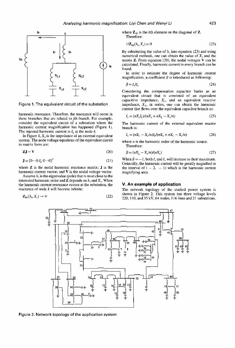
Figure 1. The equivalent circuit of the substation
Ik
harmonic resonance. Therefore, the resonance will occur in these branches that are related to jth branch. For example, consider the equivalent circuit of a substation where the harmonic current magnification has happened (Figure 1). The injected harmonic current is Ik at the node k.
In Figure 1, Xs is the impedance of an external equivalent system. The node voltage equations of the equivalent circuit in matrix form are:
ZJ = V (20 )
J = [0..-0 I k 0 . . .0] T (21)
where Z is the nodal harmonic reactance matrix; J is the harmonic current vector; and V is the nodal voltage vector.
Assume Xi is the eigenvalue (pole) that is most close to the interested harmonic order and Z depends on Xi and Xs. When the harmonic current resonance occurs at the substation, the reactance of node k will become infinite:
Zkk(h i ,Xs ) ~ ~ (22)
where Z ~ is the kth element on the diagonal of Z. Therefore:
1/Zkk(Xi, Xs) = 0 (23)
By substituting the value of Xi into equation (23) and using numerical methods, one can obtain the value of Xs and the matrix Z. From equation (20), the nodal voltages V can be calculated. Finally, harmonic current in every branch can be found.
In order to estimate the degree of harmonic current magnification, a coefficient/3 is introduced as following:
13 = ls/Ic (24)
Considering the compensation capacitor banks as an equivalent circuit that is consisted of an equivalent capacitive impedance, X~, and an equivalent reactive impedance, XL, in series, one can obtain the harmonic current that flows over the equivalent capacitor branch as:
Ic = (nXslk) / (nXs + nXL - - Xc/n) (25)
The harmonic current of the external equivalent reactor branch is:
Is = (nXL -- Xc/n)Ik / (nXs + nXL -- Xc/n) (26)
where n is the harmonic order of the harmonic source. Therefore:
13 = ( n X L - Xc /n) / (nXs) (27)
When/3 = - 1, both Is and I~ will increase to their maximum. Generally, the harmonic current will be greatly magnified in the interval of ( - 2, - 1) which is the harmonic current magnifying area.
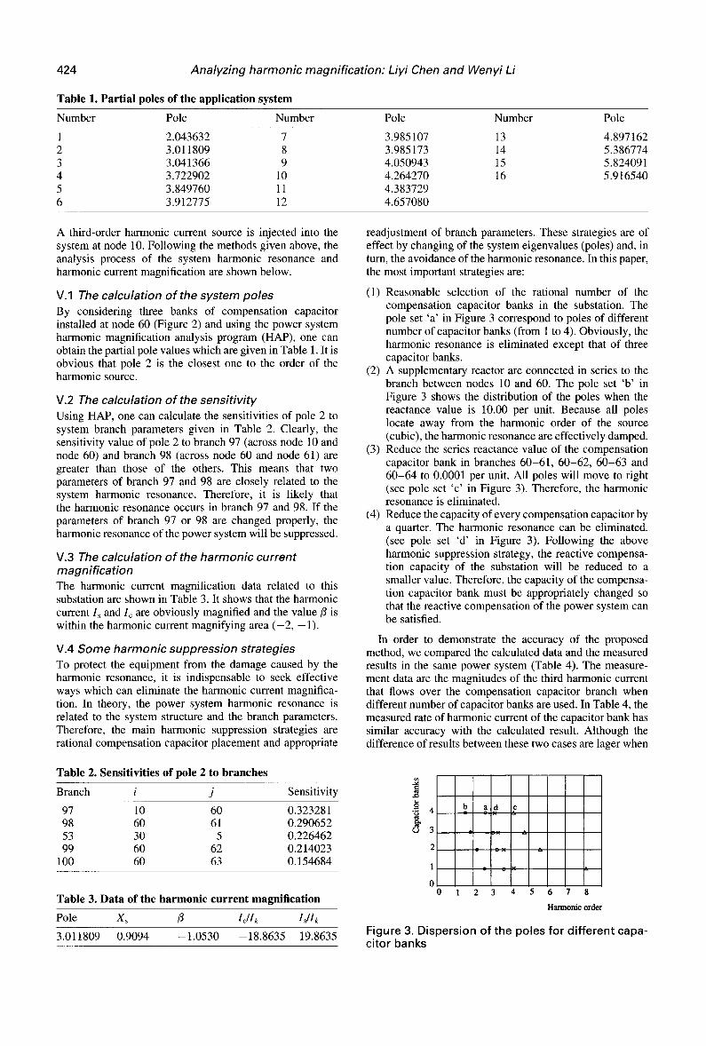
V. An example of application The network topology of the studied power system is shown in Figure 2. This system has three voltage levels 220, 110, and 35 kV, 64 nodes, 116 lines and 21 substations.
-i- 19
"T"
30 5
31
48 37 -
T T
.,IFl~
47
10
. .T_TT
20
18.,L ]7_6 T T _-- _--- =-
xs_ m q-
-I-
T 5O
7"
Figure 2. Network topology of the application system
424 Analyzing harmonic magnification: Liyi Chen and Wenyi Li
Table 1. Partial poles of the application system
Number Pole Number Pole Number Pole
1 2.043632 7 3.985107 2 3.011809 8 3.985173 3 3.041366 9 4.050943 4 3.722902 10 4.264270 5 3.849760 11 4.383729 6 3.912775 12 4.657080
13 4.897162 14 5.386774 15 5.824091 16 5.916540
A third-order harmonic current source is injected into the system at node 10. Following the methods given above, the analysis process of the system harmonic resonance and harmonic current magnification are shown below.
V.1 The calculation of the system poles By considering three banks of compensation capacitor installed at node 60 (Figure 2) and using the power system harmonic magnification analysis program (HAP), one can obtain the partial pole values which are given in Table 1. It is obvious that pole 2 is the closest one to the order of the harmonic source.
V.2 The calculation of the sensitivity Using HAP, one can calculate the sensitivities of pole 2 to system branch parameters given in Table 2. Clearly, the sensitivity value of pole 2 to branch 97 (across node 10 and node 60) and branch 98 (across node 60 and node 61) are greater than those of the others. This means that two parameters of branch 97 and 98 are closely related to the system harmonic resonance. Therefore, it is likely that the harmonic resonance occurs in branch 97 and 98. If the parameters of branch 97 or 98 are changed properly, the harmonic resonance of the power system will be suppressed.
V.3 The calculation of the harmonic current magnification The harmonic current magnification data related to this substation are shown in Table 3. It shows that the harmonic current Is and Ic are obviously magnified and the value/3 is within the harmonic current magnifying area ( - 2 , -1 ) .
V.4 Some harmonic suppression strategies To protect the equipment from the damage caused by the harmonic resonance, it is indispensable to seek effective ways which can eliminate the harmonic current magnifica- tion. In theory, the power system harmonic resonance is related to the system structure and the branch parameters. Therefore, the main harmonic suppression strategies are rational compensation capacitor placement and appropriate
Table 2. Sensitivities of pole 2 to branches
Branch i j Sensitivity
97 10 60 0.323281 98 60 61 0.290652 53 30 5 0.226462 99 60 62 0.214023
100 60 63 0.154684
Table 3. Data of the harmonic current magnification
Pole Xs /3 Icllk Isllk
3.011809 0.9094 --1.0530 --18.8635 19.8635
readjustment of branch parameters. These strategies are of effect by changing of the system eigenvalues (poles) and, in turn, the avoidance of the harmonic resonance. In this paper, the most important strategies are:
(1) Reasonable selection of the rational number of the compensation capacitor banks in the substation. The pole set 'a ' in Figure 3 correspond to poles of different number of capacitor banks (from 1 to 4). Obviously, the harmonic resonance is eliminated except that of three capacitor banks.
(2) A supplementary reactor are connected in series to the branch between nodes 10 and 60. The pole set 'b ' in Figure 3 shows the distribution of the poles when the reactance value is 10.00 per unit. Because all poles locate away from the harmonic order of the source (cubic), the harmonic resonance are effectively damped.
(3) Reduce the series reactance value of the compensation capacitor bank in branches 60-61, 60-62, 60-63 and 60-64 to 0.0001 per unit. All poles will move to right (see pole set 'c ' in Figure 3). Therefore, the harmonic resonance is eliminated.
(4) Reduce the capacity of every compensation capacitor by a quarter. The harmonic resonance can be eliminated. (see pole set 'd ' in Figure 3). Following the above harmonic suppression strategy, the reactive compensa- tion capacity of the substation will be reduced to a smaller value. Therefore, the capacity of the compensa- tion capacitor bank must be appropriately changed so that the reactive compensation of the power system can be satisfied.
In order to demonstrate the accuracy of the proposed method, we compared the calculated data and the measured results in the same power system (Table 4). The measure- ment data are the magnitudes of the third harmonic current that flows over the compensation capacitor branch when different number of capacitor banks are used. In Table 4, the measured rate of harmonic current of the capacitor bank has similar accuracy with the calculated result. Although the difference of results between these two cases are lager when
X3
ro
4
3
2
1
0 0 1
b a d c
2 3 4 5 6 7 8
Harmonic order
Figure 3. Dispersion of the poles for different capa- citor banks
Analyzing harmonic magnification: Liyi Chen and Wenyi Li 425
Table 4. Measured and calculated data of the harmonic current for different capacitor banks
Bank 1 2 3 4
Measured Ic/Ik 1.000 1.980 5.250 1.813 Calculated Ic/Ik 1.0D0 1.762 31.240 2.058
proposed. The accuracy of this method has been demon- strated. The proposed method can be used to detect the location of harmonic resonance, to obtain the harmonic current magnification information at a substation and to find the effective harmonic suppression strategies.
harmonic resonance occurs because of the inevitable difference of conditions between calculation and measure- ment, it can reflect the relationship between harmonic current magnification and the different number of capacitor banks.
VI. Conclusion A method of analyzing power system resonance and harmonic current magnification based on the calculation of poles and its sensitivity to branch parameters has been
VII. References 1. Wagner, V. E., Effects of harmonic on equipment. IEEE Trans. Power
Delivery, 1993, 8(2), 672-680. 2. Ortmeyer, T. H. and Zehar, K., Distribution system harmonic design.
IEEE Trans. Power Delivery, 1991, 6(1), 289-294. 3. Hartana, R. K. and Richards, G. G., Optimum filter design for distribu-
tion feedes with multiple harmonic sources. Elect. Power System Res., 1992, 23(2), 103-113.
4. Mahmoud, A. A. and Shultz, R. D., A method for analysing harmonic distribution in A. C. power systems. IEEE Trans. Power Appar. Sysyems, 1982, 101, 1815-1824.
5. Van Ness, J. E., Inverse iteration method for finding eigenvectors. IEEE Trans. Automatic Control, 1969, 14, 63-66.
![Hardness Magnification for all Sparse NP Languages · 2021. 5. 15. · Hardness Magnification for MCSP (Other Hardness Magnification Results) 1−𝜀-approximate Clique [Sri’03]](https://img.pdfslide.us/doc/110x75/61466b267599b83a5f003575/hardness-magnification-for-all-sparse-np-languages-2021-5-15-hardness-magnification.jpg)