Embed Size (px)
Citation preview

1
New Zealand Inter Island HVDCPole 3 Project
IPENZ Presentation
18 February 2010Wellington
Peter Griffiths – Project Director HVDC
2
NZ Inter Island HVDC Link
• NZ HVDC Inter Island link:– only high voltage transmission
link between the South and North Islands
– balances the distribution of energy between islands, helping to carry electricity from where it is generated to where it is needed.
• Haywards & Benmore contain both Pole 1 & 2 of the HVDC link and are critical parts of New Zealand’s national grid
Benmore
Haywards
Benmore
Haywards
3
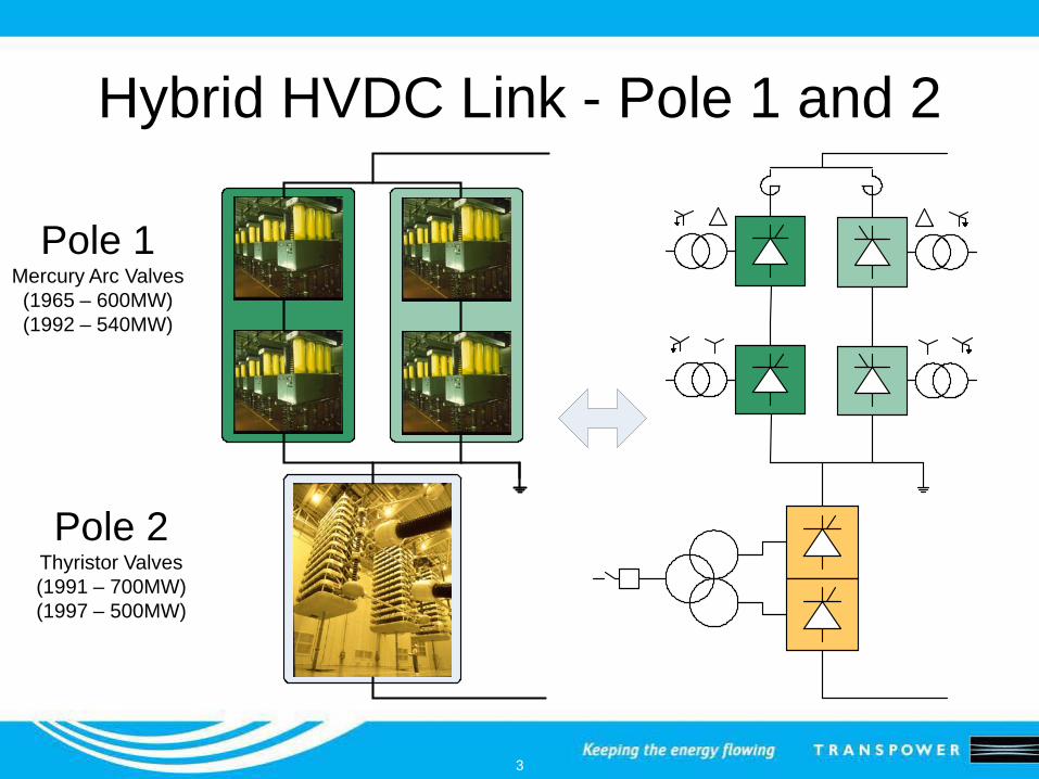
Hybrid HVDC Link - Pole 1 and 2
Pole 1Mercury Arc Valves(1965 – 600MW)(1992 – 540MW)
Pole 2Thyristor Valves(1991 – 700MW)(1997 – 500MW)
4
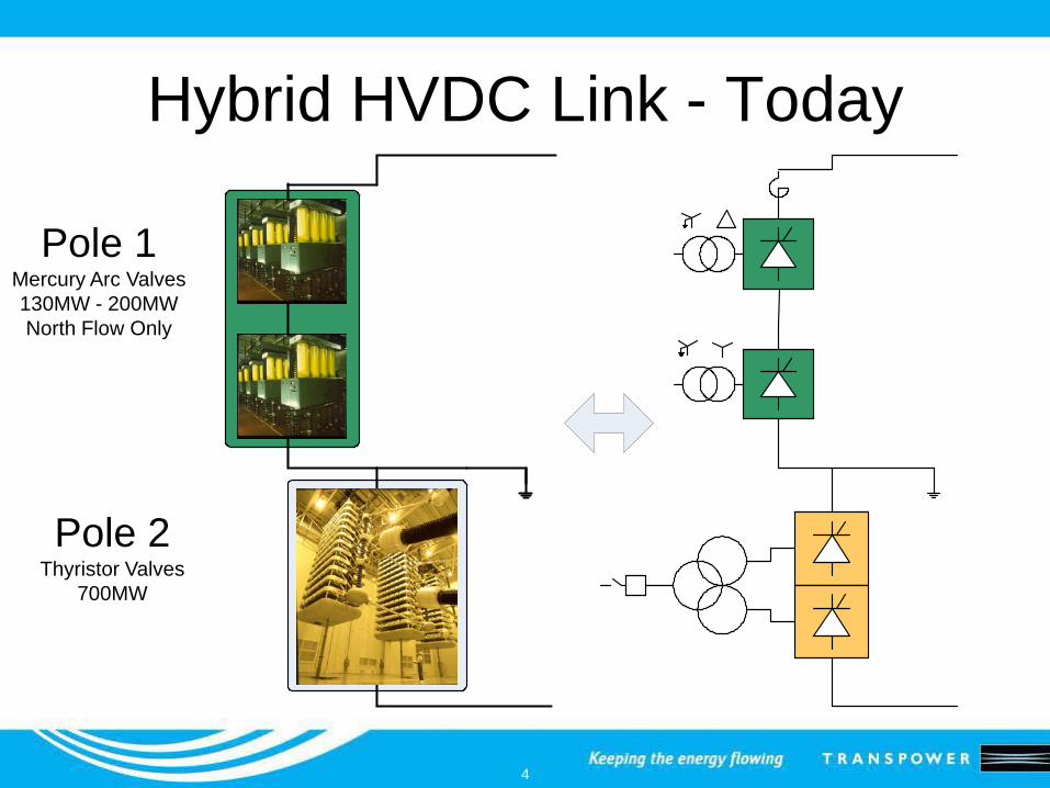
Hybrid HVDC Link - Today
Pole 1Mercury Arc Valves130MW - 200MWNorth Flow Only
Pole 2Thyristor Valves
700MW
5
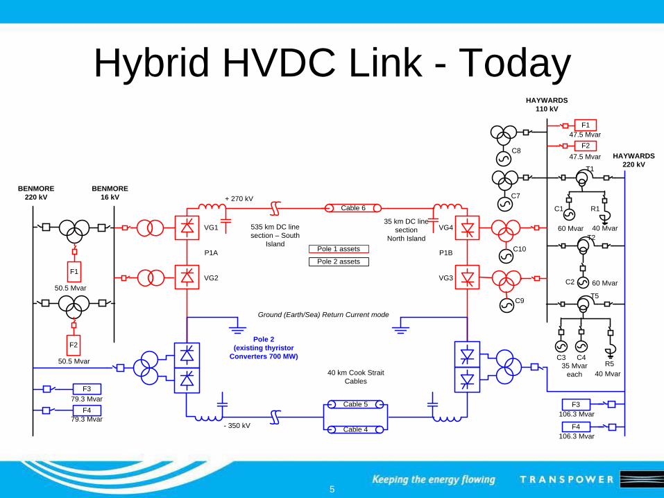
Hybrid HVDC Link - Today
BENMORE220 kV
HAYWARDS220 kV
Cable 6
Cable 4
Pole 2 (existing thyristor
Converters 700 MW)
535 km DC line section – South
Island
35 km DC line section
North Island
40 km Cook Strait Cables
+ 270 kV
- 350 kV
Cable 5
HAYWARDS110 kV
C7BENMORE
16 kV
Ground (Earth/Sea) Return Current mode
F479.3 Mvar
79.3 Mvar
F3
F3
F4
106.3 Mvar
106.3 Mvar
C1
60 Mvar
T1
C4C335 Mvar
each
T5
C2 60 Mvar
T2
40 MvarR5
40 Mvar
R1
F2
50.5 Mvar
50.5 Mvar
F1
F247.5 Mvar
47.5 MvarC8
C9
C10Pole 1 assets
Pole 2 assets
VG3
VG4
P1B
VG2
VG1
P1A
F1
6
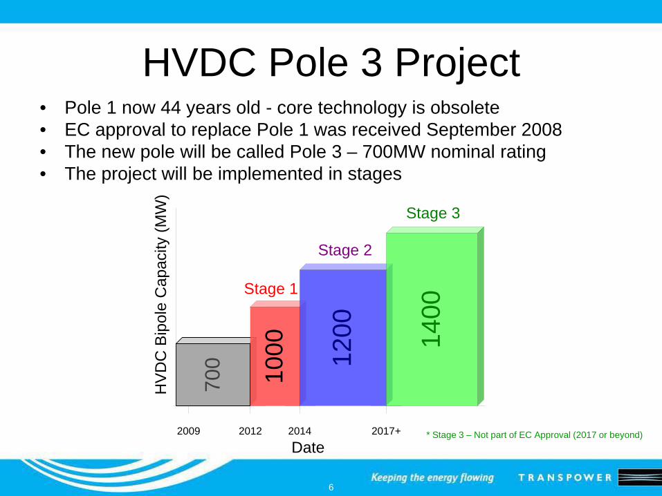
HVDC Pole 3 Project• Pole 1 now 44 years old - core technology is obsolete• EC approval to replace Pole 1 was received September 2008• The new pole will be called Pole 3 – 700MW nominal rating• The project will be implemented in stages
* Stage 3 – Not part of EC Approval (2017 or beyond)
700
HV
DC
Bip
ole
Cap
acity
(MW
)
2009 2012 2014 2017+
1000
Date
Stage 1
Stage 2
Stage 3
1200 14
00
7
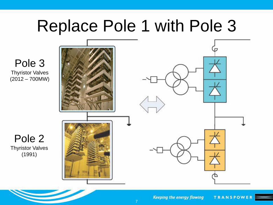
Replace Pole 1 with Pole 3
Pole 3Thyristor Valves(2012 – 700MW)
Pole 2Thyristor Valves
(1991)
8
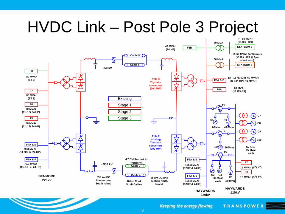
HVDC Link – Post Pole 3 Project
BENMORE 220kV
HAYWARDS 220kV
Pole 2 existing
Thyristor converters (700 MW)
535 km DC line section South Island
40 km Cook Strait Cables
+ 350 kV
- 350 kV
HAYWARDS 110kV
C7
F4A & B
F3A & B
79.3 MVAr(11 /13 & 24 HP)
Existing
C7-C1065 Mvar
each
Cable 6
Cable 4
Cable 5
4 0 Mvar
C1
60 Mvar
T1
C4C335 Mvar
each
T5
C2 60 Mvar
T2
R5
4 0 Mvar
R1
35 km DC line section North
Island
Pole 3 Thyristor
converters (700 MW)
106.3 MVAr(12HP & 24HP)
Stage 1Stage 2Stage 3
F7
F816 MVAr (5th/ 7th)
16 MVAr (5th/ 7th)
C8
C9
C10
F5A & B(A : 11 /13 /24) 60 MVAR
(B : 24 HP) 49 MVAR
F5
F7
STATCOM 2
80 MVAr (11 /13/ 24 HP)
60 MVA
60 MVA
STATCOM 1
+/- 60 MVAr continuous (+110 / -109 @ 1pu
short term)
F6
F8
49 MVAr (24 HP) F6B
+/- 60 MVAr (+110 / -109)
Cable 7
4th Cable (not in tenders)
F6A 60 MVAr (11 /13 /24)
80 MVAr (11 /13/ 24 HP)
80 MVAr (ST 3)
80 MVAr (ST 3)
79.3 MVAr(11 /13 & 24 HP)
106.3 MVAr(12HP & 24HP)
F3A & B
F4A & B
9
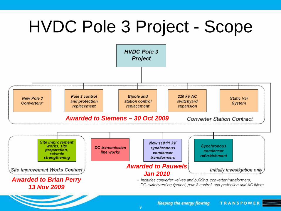
HVDC Pole 3 Project - Scope
Awarded to Siemens – 30 Oct 2009
Awarded to Brian Perry13 Nov 2009
Awarded to PauwelsJan 2010
10
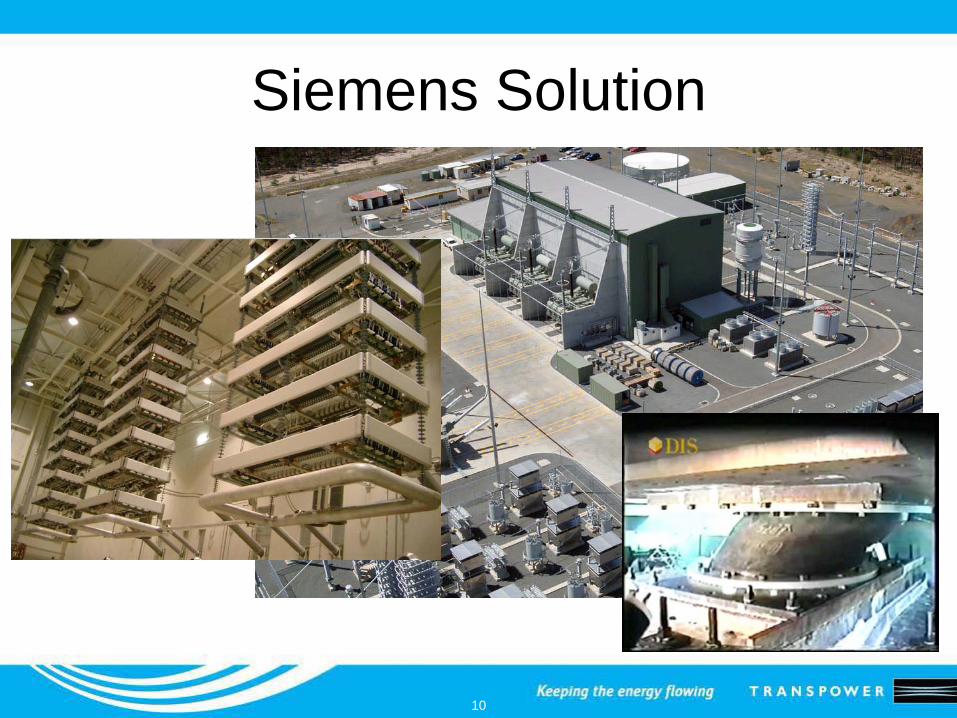
Siemens Solution
11
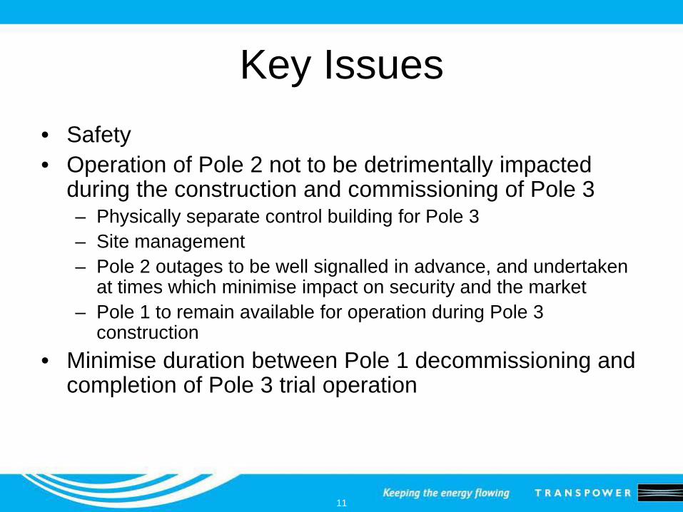
Key Issues• Safety• Operation of Pole 2 not to be detrimentally impacted
during the construction and commissioning of Pole 3– Physically separate control building for Pole 3– Site management– Pole 2 outages to be well signalled in advance, and undertaken
at times which minimise impact on security and the market– Pole 1 to remain available for operation during Pole 3
construction• Minimise duration between Pole 1 decommissioning and
completion of Pole 3 trial operation
12
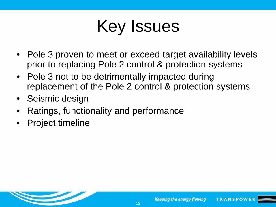
Key Issues• Pole 3 proven to meet or exceed target availability levels
prior to replacing Pole 2 control & protection systems• Pole 3 not to be detrimentally impacted during
replacement of the Pole 2 control & protection systems• Seismic design• Ratings, functionality and performance• Project timeline
13
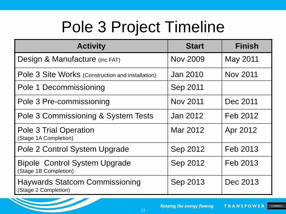
Pole 3 Project TimelineActivity Start Finish
Design & Manufacture (inc FAT) Nov 2009 May 2011
Pole 3 Site Works (Construction and installation) Jan 2010 Nov 2011Pole 1 Decommissioning Sep 2011
Pole 3 Pre-commissioning Nov 2011 Dec 2011
Pole 3 Commissioning & System Tests Jan 2012 Feb 2012
Pole 3 Trial Operation(Stage 1A Completion)
Mar 2012 Apr 2012
Pole 2 Control System Upgrade Sep 2012 Feb 2013
Bipole Control System Upgrade(Stage 1B Completion)
Sep 2012 Feb 2013
Haywards Statcom Commissioning(Stage 2 Completion)
Sep 2013 Dec 2013
14
2
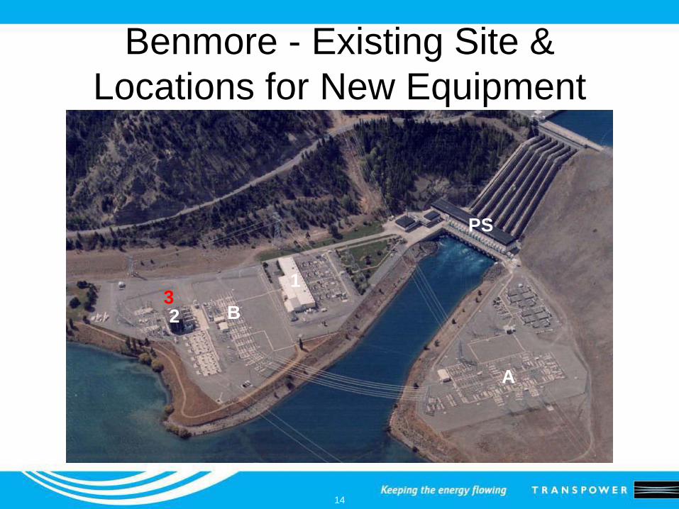
Benmore - Existing Site &Locations for New Equipment
1
A
B
PS
3
15
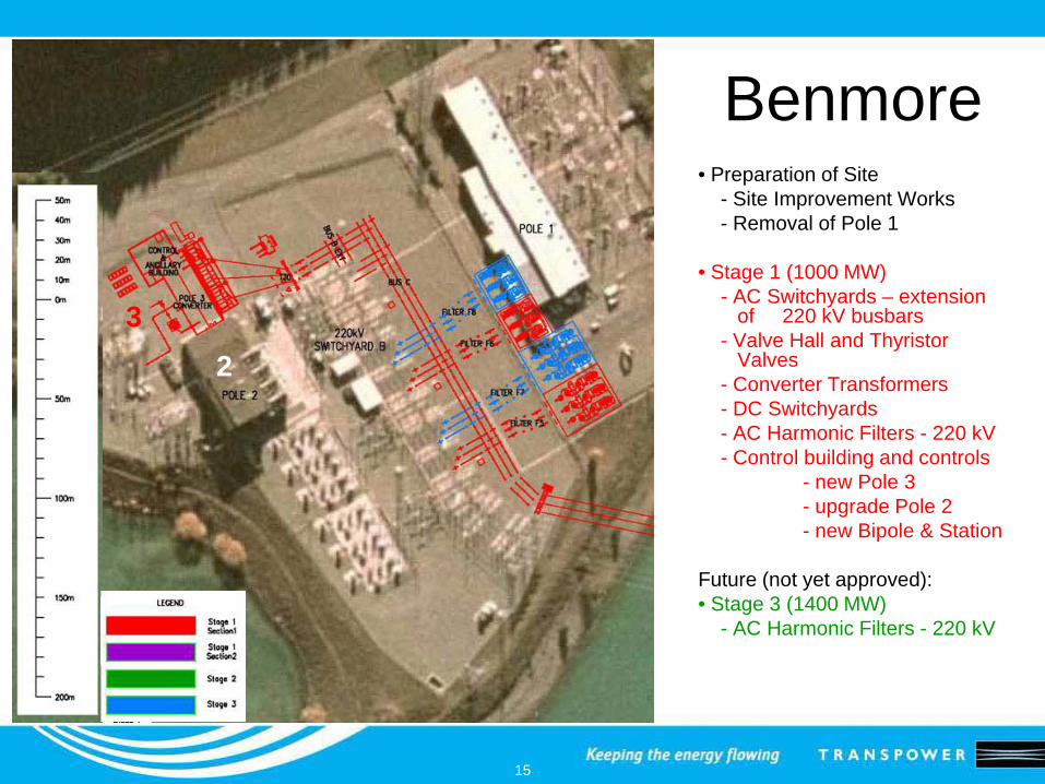
Benmore• Preparation of Site
- Site Improvement Works- Removal of Pole 1
• Stage 1 (1000 MW)- AC Switchyards – extension
of 220 kV busbars- Valve Hall and Thyristor
Valves- Converter Transformers- DC Switchyards- AC Harmonic Filters - 220 kV- Control building and controls
- new Pole 3- upgrade Pole 2- new Bipole & Station
Future (not yet approved):• Stage 3 (1400 MW)
- AC Harmonic Filters - 220 kV
23
16
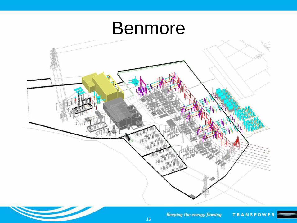
Benmore
17
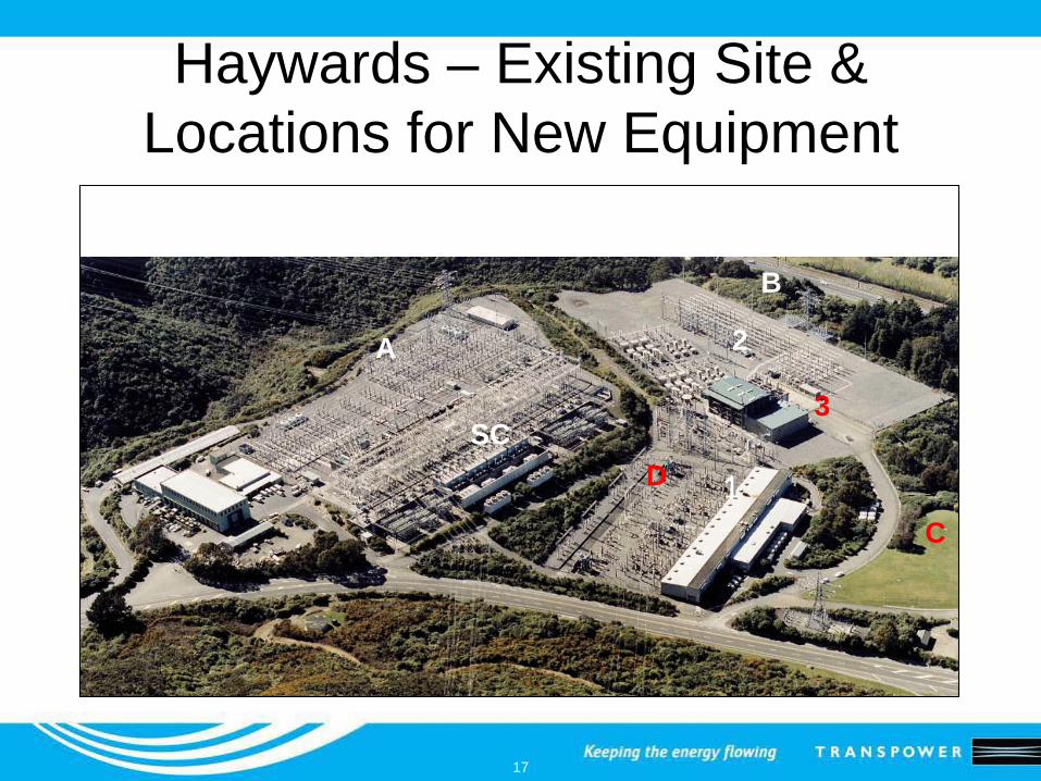
Haywards – Existing Site &Locations for New Equipment
1
2A
B
SC
C
3
D
18
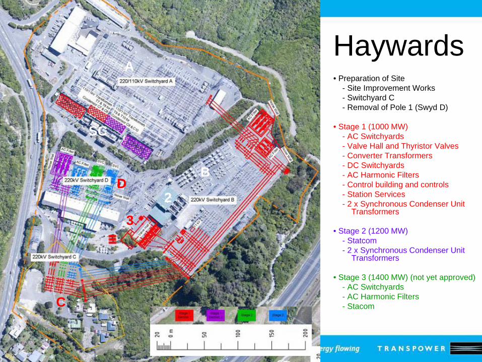
Haywards• Preparation of Site
- Site Improvement Works- Switchyard C- Removal of Pole 1 (Swyd D)
• Stage 1 (1000 MW)- AC Switchyards - Valve Hall and Thyristor Valves- Converter Transformers- DC Switchyards- AC Harmonic Filters- Control building and controls- Station Services- 2 x Synchronous Condenser Unit
Transformers
• Stage 2 (1200 MW)- Statcom- 2 x Synchronous Condenser Unit
Transformers
• Stage 3 (1400 MW) (not yet approved)- AC Switchyards - AC Harmonic Filters- Stacom
2
A
B
SC
C
3
D
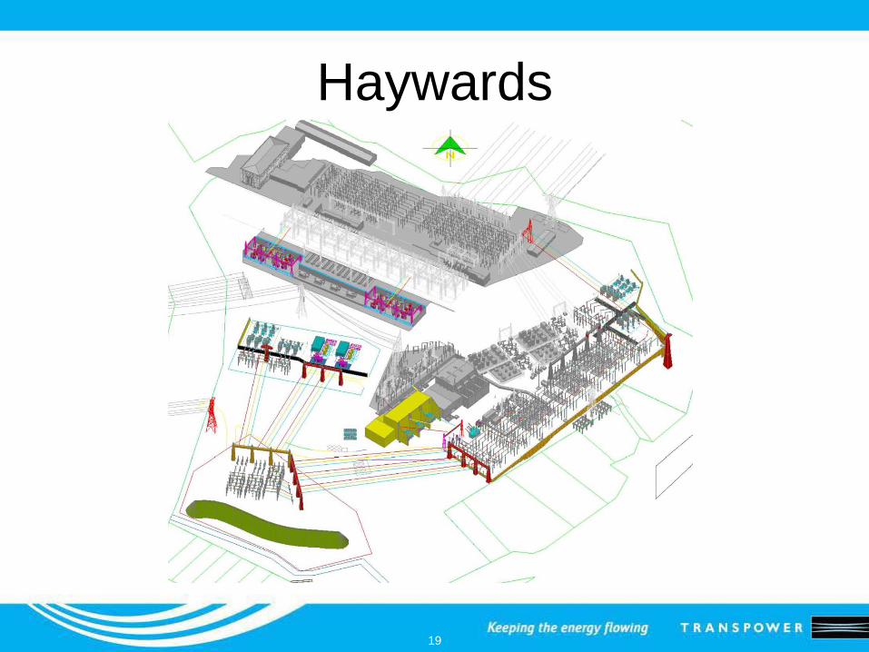
19
Haywards
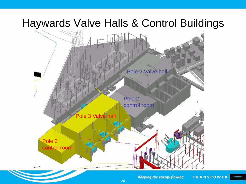
20
Haywards Valve Halls & Control Buildings
Pole 3 Valve hall
Pole 3 control room
Pole 2 control room
Pole 2 Valve hall
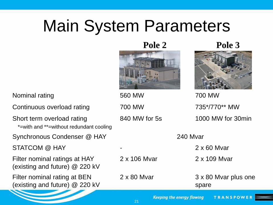
21
Pole 2 Pole 3
Nominal rating 560 MW 700 MW
Continuous overload rating 700 MW 735*/770** MW
Short term overload rating*=with and **=without redundant cooling
840 MW for 5s 1000 MW for 30min
Synchronous Condenser @ HAY 240 Mvar
STATCOM @ HAY - 2 x 60 Mvar
Filter nominal ratings at HAY (existing and future) @ 220 kV
2 x 10⁶ Mvar 2 x 10⁹ Mvar
Filter nominal rating at BEN (existing and future) @ 220 kV
2 x 80 Mvar 3 x 80 Mvar plus one spare
Main System Parameters
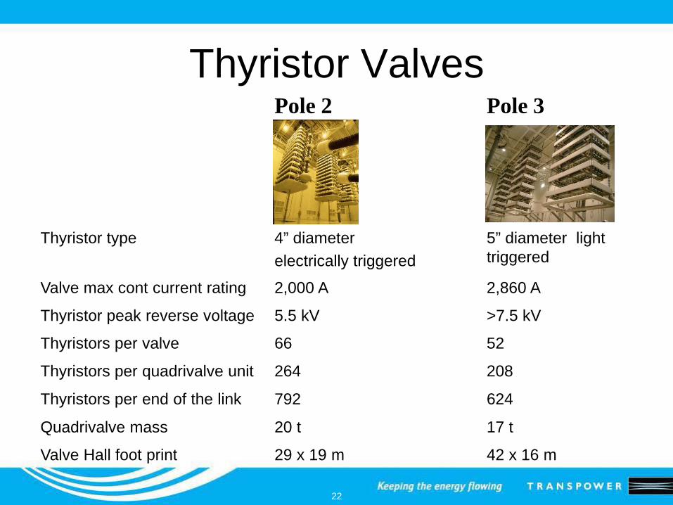
22
Thyristor ValvesPole 2 Pole 3
Thyristor type 4” diameterelectrically triggered
5” diameter light triggered
Valve max cont current rating 2,000 A 2,860 A
Thyristor peak reverse voltage 5.5 kV >7.5 kV
Thyristors per valve 66 52
Thyristors per quadrivalve unit 264 208
Thyristors per end of the link 792 624
Quadrivalve mass 20 t 17 t
Valve Hall foot print 29 x 19 m 42 x 16 m
23
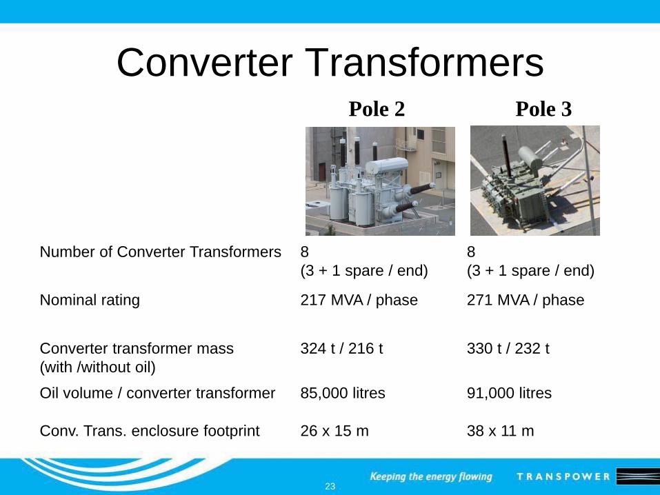
Converter TransformersPole 2 Pole 3
Number of Converter Transformers 8(3 + 1 spare / end)
8(3 + 1 spare / end)
Nominal rating 217 MVA / phase 271 MVA / phase
Converter transformer mass(with /without oil)
324 t / 216 t 330 t / 232 t
Oil volume / converter transformer 85,000 litres 91,000 litres
Conv. Trans. enclosure footprint 26 x 15 m 38 x 11 m
24
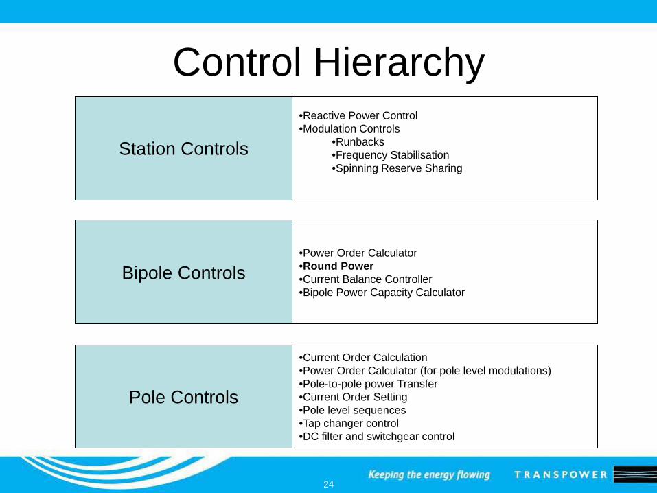
Control Hierarchy
Station Controls
Bipole Controls
Pole Controls
•Reactive Power Control•Modulation Controls
•Runbacks•Frequency Stabilisation•Spinning Reserve Sharing
•Power Order Calculator•Round Power•Current Balance Controller•Bipole Power Capacity Calculator
•Current Order Calculation•Power Order Calculator (for pole level modulations)•Pole-to-pole power Transfer•Current Order Setting•Pole level sequences•Tap changer control•DC filter and switchgear control

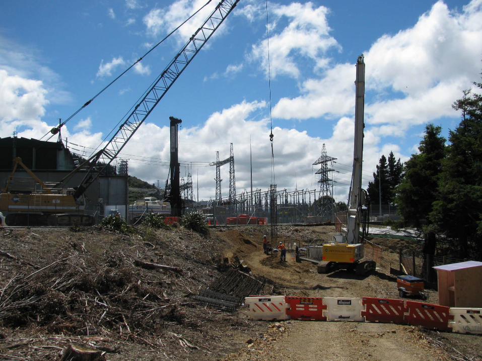
25
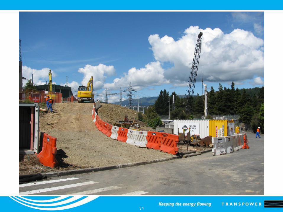
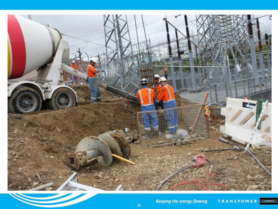
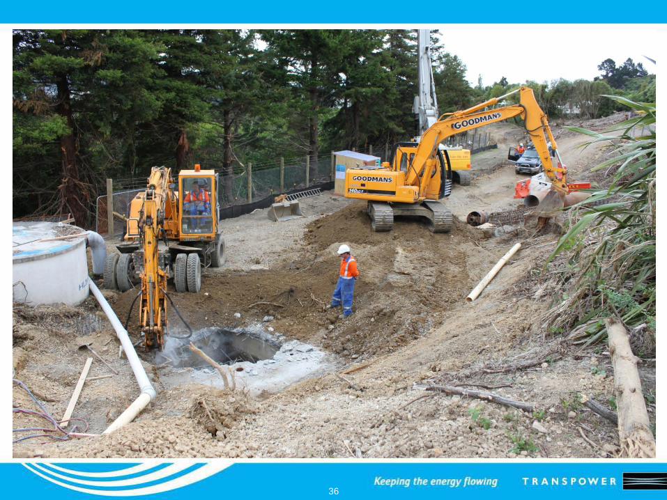
Site Establishment at Haywards

26
Switchyard B (Pole 3 Area)
27
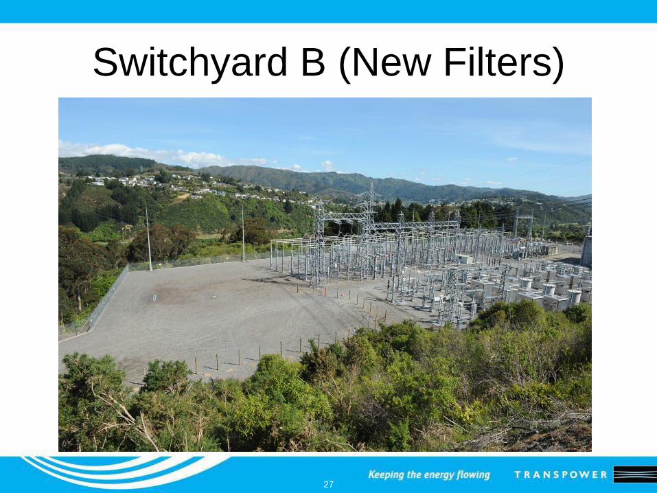
Switchyard B (New Filters)
28
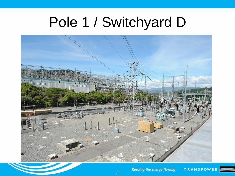
Pole 1 / Switchyard D
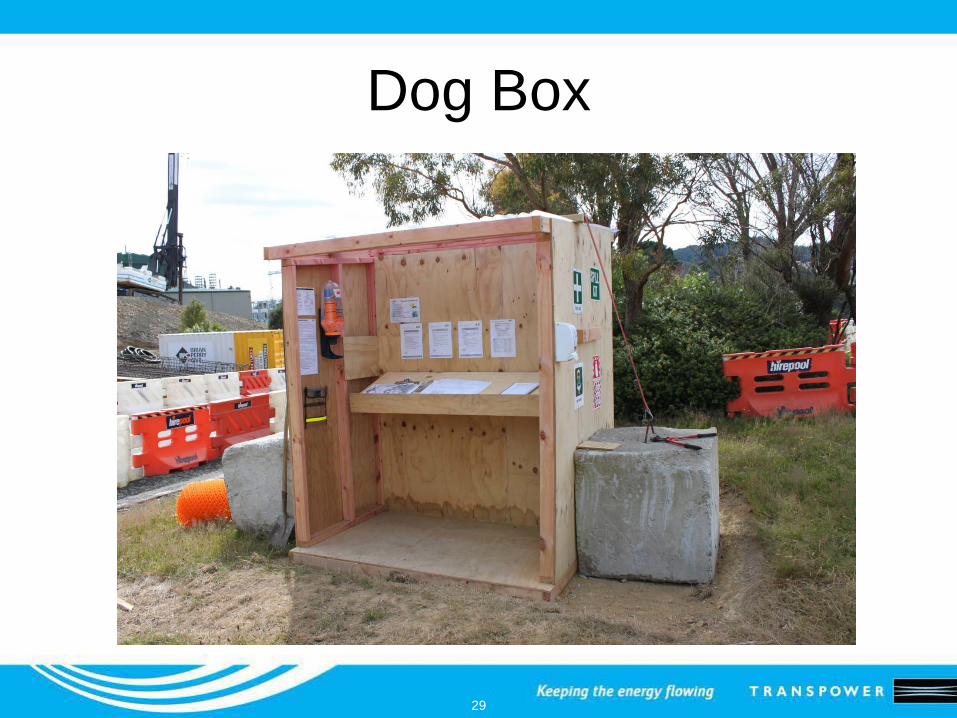
29
Dog Box

30
Removing Kaitawa Street Houses
31
32
33
34
35
36
37
Planning for Commissioning
• Commissioning of Pole 3, the subsequent Pole 2 control system upgrade and bipole commissioning will require a high degree of communication, support and coordination amongst industry participants
• A Pole 3 Commissioning Industry Advisory Group will be established later this month
38
Questions ?


![A bi-pole ± 285 kV HVDC line HVDC-VSC: transmission ...TG#08].pdf · for building multi-terminal HVDC schemes, as reversing power fl ow does not involve a change of DC polarity,](https://img.pdfslide.us/doc/110x75/5e64eaca2594e126f07d0fa9/a-bi-pole-285-kv-hvdc-line-hvdc-vsc-transmission-tg08pdf-for-building.jpg)