Embed Size (px)
Citation preview
74-WA- GT-10
' ' 't1 L.'A I The Society shall not be responsible for statements or opinionsadvanced in papers or in discussion at meetings of the Societyor of its Divisions or Sections, or printed in its publications.
' Discussion is printed only if the paper is published in an ASMEjournal or Proceedings.Released for general publication upon presentation.Full credit should be given to ASME, the Professional Division,
$3.00 PER COPY and the author (s).
$1.00 TO ASME MEMBERS
A NOx Correlation Method for Gas TurbineCombustors Based on NOx FormationAssumptions
GEZA VERMES
Fellow Engineer,Gas Turbine SystemsEngineering Department,Westinghouse Electric Corp.,Lester, Pa.Mem. ASME
Based on a simplified description of the combustion process in the primary zone of a cantype gas turbine combustor, a generalized NOx versus fuel flow relationship is proposed.Using this relationship and considerations based on chemical kinetics, the effect of com-bustor inlet pressure, inlet temperature and air residence time on NOx formation is inves-tigated in industrial and automotive type combustion chambers. Data reported in the litera-ture and original test work is cited to substantiate the validity of the assumptions. Based onthe findings, a simple method is presented to predict NOx emissions of a gas turbinecombustor under conditions which differ substantially from those of the test run. The as-sumptions may be used to assemble a model for a priori prediction of NOx emissions in agiven combustion geometry.
Contributed by the Gas Turbine Division of The American Society of Mechanical Engineers for presenta-tion at the Winter Annual Meeting, New York, N. V., November 17-22, 1974. Manuscript received atASME Headquarters August 2, 1974.
Copies will be available until September 1, 1975.
AMERICAN SOCIETY OF MECHANICAL ENGINEERS, UNITED ENGINEERING CENTER, 345 EAST 47th STREET, NEW YORK, N.Y. 10017
Copyright © 1974 by ASME
Downloaded From: http://ebooks.asmedigitalcollection.asme.org/pdfaccess.ashx?url=/data/conferences/asmep/84087/ on 06/12/2018 Terms of Use: http://www.asme.org/about-asme/terms-of-use
A NOx Correlation Method for Gas TurbineCombustors Based on NOx FormationAssumptions
GEZA VERMES
INTRODUCTION AND OBJECTIVE
The rapid increase in gas turbine pressure
ratios and temperature levels during the last
few years has the consequence (among many other
things) that gas turbine combustor chambers underdevelopment will have to operate very soon undercombustor ambient conditions different from those
presently in practice. It is of practicalinterest to know what NOx levels can be expected
from a given combustor geometry in these advanced
machines, Another question of practical signifi-cance is the influence of regeneration on NOxformation. It is also of interest to compare the
NOx emissions of different gas turbines: this is
not meaningful when the available test data must
refer to different combustor ambients,
It is the objective of this paper to proposea method which provides answers to the foregoingquestions,
VARIABLES CONSIDERED
The influence of the following variableson NOx will be considered:
• Fuel flow (or fuel/air ratio)• Residence time
• Combustor inlet pressure
• Combustor inlet temperature,
ASSUMPTIONS
It will be assumed that the fuel has onlynegligible nitrogen content. It will be further
assumed that at one point, NOx measurement was
performed under known operating conditions. It
will be assumed that the influence of air humidityon NOx formation can be assessed (1).
It will be further assumed that NOx forma-tion in a gas turbine combustor follows a
1Numbers in parentheses designate Refer-
ences at end of paper,
qualitative model as described below,
THE RICH-LEAN MODEL OF NOx FORMATION IN THE GAS
TURBINE COMBUSTOR
The type of gas turbine combustor discussedin this paper is the can type, This combustorcan be considered to be a cylinder, wide open on
one end discharging the exhaust gases; the fuel
injection takes place at the opposite end in theform of a shallow cone spray at the centerline
of the cylinder, the spray emerging from a
pressure atomizing nozzle,For the purposes of this paper, the absolutr
pressure and temperature of the air around the
combustor basket will be considered as "combustor
inlet pressure (temperature)"; it will be assumed
that the difference between total pressure and
static pressure is negligible around the combustor
basket.Note that the combustor inlet temperature
is close to the compressor exit temperature in a
non-regenerative machine, but it is much higher
in the regenerative turbine,The other important temperature is the
combustor exit temperature, usually close to the
turbine inlet temperature.The third temperature level which has a
bearing on NOx formation is the temperature of
the gas mixture in the primary zone; this level
is on the order of the flame temperature.It was shown in Reference (2) that the
combustion reactions are at least one order ofmagnitude faster than the NOx formation mechanism,
which may be described by the often-quotedZeldovich mechanism (3)a It follows from theZeldovich mechanism that in the fuel rich areas
of the combustor, NOx formation is negligible.As the spray itself is, quite obviously, extremely
fuel rich, the central cylindrical zone of thecombustor upstream end containing the spray can
be excluded from the NOx producing areas. As
N
Downloaded From: http://ebooks.asmedigitalcollection.asme.org/pdfaccess.ashx?url=/data/conferences/asmep/84087/ on 06/12/2018 Terms of Use: http://www.asme.org/about-asme/terms-of-use
>ST ATOMIZER
BASED ON NORSTERLEFEBVRE (2), FIG.21
60 80 100 120 140
OVERALL AIR- FUEL RATIO
NO XPPM(VOL)
NODE I I MODE II I MODE III(RICH) (LEAN) ("UPSWING')
pT=TCOMB. IN -TCOMB.OUT —^OR FUEL FLOWOR FUEL/AIR RATIO — '
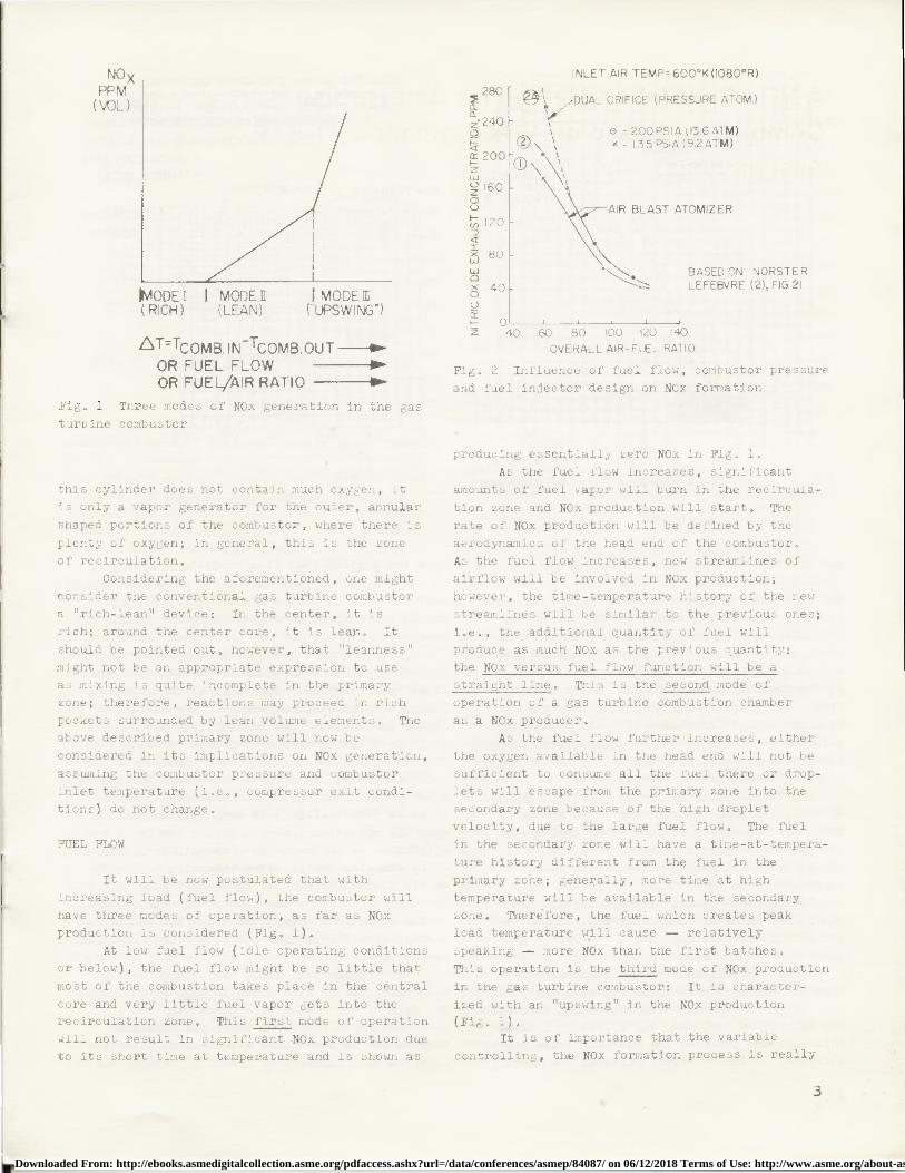
Fig. 1 Three modes of NOx generation in the gasturbine combustor
this cylinder does not contain much oxygen, itis only a vapor generator for the outer, annular
shaped portions of the combustor, where there is
plenty of oxygen; in general, this is the zoneof recirculation.
Considering the aforementioned, one mightconsider the conventional gas turbine combustor
a "rich-lean" device: In the center, it isrich; around the center core, it is lean. It
should be pointed out, however, that "leanness"
might not be an appropriate expression to useas mixing is quite incomplete in the primaryzone; therefore, reactions may proceed in richpockets surrounded by lean volume elements. Theabove described primary zone will now be
considered in its implications on NOx generation,
assuming the combustor pressure and combustor
inlet temperature (i.e., compressor exit condi-tions) do not change.
FUEL FLOW
It will be now postulated that with
increasing load (fuel flow), the combustor will
have three modes of operation, as far as NOxproduction is considered (Fig. 1).
At low fuel flow (idle operating conditions
or below), the fuel flow might be so little that
most of the combustion takes place in the central
core and very little fuel vapor gets into therecirculation zone. This first mode of operation
will not result in significant NOx production due
to its short time at temperature and is shown as
INLET AIR TEMP=600°K(1080°R)
280®,ZDUAL ORIFICE (PRESSURE ATOM.)
Z 240 ,p 0 -200PSIA03.6ATM)
x- 135PSIA(9.2ATM)200 O
zwZ 1600U
N 120
80
w00 40U
oZ 40
Fig. 2 Influence of fuel flow, combustor pressure
and fuel injector design on NOx formation
producing essentially zero NOx in Fig. 1.As the fuel flow increases, significant
amounts of fuel vapor will burn in the recircula-
tion zone and NOx production will start. The
rate of NOx production will be defined by the
aerodynamics of the head end of the combustor.As the fuel flow increases, new streamlines ofairflow will be involved in NOx production;
however, the time-temperature history of the new
streamlines will be similar to the previous ones;
i.e., the additional quantity of fuel willproduce as much NOx as the previous quantity:the NOx versus fuel flow function will be astraight line. This is the second mode ofoperation of a gas turbine combustion chamber
as a NOx producer.
As the fuel flow further increases, either
the oxygen available in the head end will not be
sufficient to consume all the fuel there or drop-lets will escape from the primary zone into thesecondary zone because of the high droplet
velocity, due to the large fuel flow. The fuel
in the secondary zone will have a time-at-tempera-
ture history different from the fuel in the
primary zone; generally, more time at hightemperature will be available in the secondaryzone. Therefore, the fuel which creates peakload temperature will cause — relatively
speaking — more NOx than the first batches.
This operation is the third mode of NOx production
in the gas turbine combustor: It is character-
ized with an "upswing" in the NOx production(Fig. 1).
It is of importance that the variable
controlling, the NOx formation process is really
3
Downloaded From: http://ebooks.asmedigitalcollection.asme.org/pdfaccess.ashx?url=/data/conferences/asmep/84087/ on 06/12/2018 Terms of Use: http://www.asme.org/about-asme/terms-of-use
NO, PPM (VOL)
28(
26(
24(
18(
16(
14(
12(
101
81
61
4
21
• ri:•1■•■■•■■■■
■11C■1l■■■■■■
■■ ■■■
N =. N ■■■■■■■■■■■ ■■■ ■■•ONE•■■■■■NOON ■■■■■■■■■so•OMEN
■■■■■■■ r
/a►. .
■•■■■■■■
■■■■■
■■■C■■■■■■■■■■■MEMO
'■■.■.■..■■■■■■■■■■■A.
■■■.
■on■►
0U■■■
■■■■■■■■■■OMEN■■■■■■■
■■NESS.■■■■!■ ■■■■■■■NONE••■■■■^■■'•■■
■• ■••••••■■■■■■■■■■■■■■■■ • ■■■■■■■•••••••
' ■■■■■■■f'// ■N■■■■■■■■■•■■■■■■V4U ■■■■■■■■■■•■.
■■■■■■UI ■■■■■■■■■■■■■■ - ■■
•
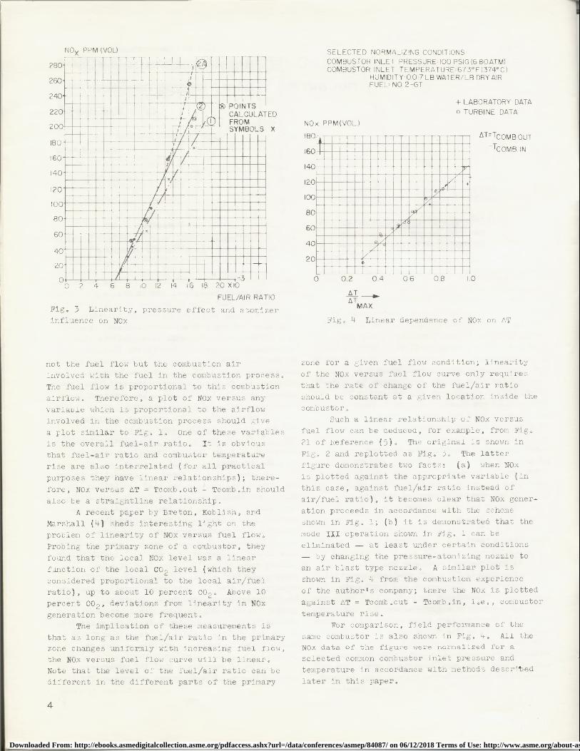
SELECTED NORMALIZING CONDITIONSCOMBUSTOR INLET PRESSURE 100 PSIG (6 8OATM)COMBUSTOR INLET TEMPERATURE:673°F(374°C)
HUMIDITY - 0.017 LB WATER/LB DRY AIRFUEL: NO.2-GT
+ LABORATORY DATAo TURBINE DATA
NOx PPM(VOL.)
AT = TCOMB OUT
-TCOMB. IN
20
60
0 0.2 0.4 0.6 0.8 1.0V L Y V V IV IL I1 1 V iv Iv -
FUEL/AIR RATIO
Fig, 3 Linearity, pressure effect and atomizerinfluence on NOx
--0-
A MAX.
Fig, 4 Linear dependence of NOx on AT
not the fuel flow but the combustion airinvolved with the fuel in the combustion process.
The fuel flow is proportional to this combustion
airflow, Therefore, a plot of NOx versus any
variable which is proportional to the airflow
involved in the combustion process should give
a plot similar to Fig, 1. One of these variables
is the overall fuel-air ratio, It is obviousthat fuel-air ratio and combustor temperature
rise are also interrelated (for all practical
purposes they have linear relationships); there-
fore, NOx versus AT = Tcomb,out - Tcomb,in should
also be a straightline relationship,A recent paper by Breton, Koblish, and
Marshall (4) sheds interesting light on the
problem of linearity of NOx versus fuel flow,
Probing the primary zone of a combustor, they
found that the local NOx level was a linear
function of the local CO 2 level (which they
considered proportional to the local air/fuel
ratio), up to about 10 percent CO 2 . Above 10
percent CO 2 , deviations from linearity in NOx
generation become more frequent,The implication of these measurements is
that as long as the fuel/air ratio in the primaryzone changes uniformly with increasing fuel flow,
the NOx versus fuel flow curve will be linear.Note that the level of the fuel/air ratio can bedifferent in the different parts of the primary
zone for a given fuel flow condition; linearity
of the NOx versus fuel flow curve only requires
that the rate of change of the fuel/air ratio
should be constant at a given location inside the
combustor,Such a linear relationship of NOx versus
fuel flow can be deduced, for example, from Fig,
21 of Reference (5), The original is shown in
Fig. 2 and replotted as Fig, 3, The latter
figure demonstrates two facts: (a) when NOx
is plotted against the appropriate variable (in
this case, against fuel/air ratio instead of
air/fuel ratio), it becomes clear that NOx gener-ation proceeds in accordance with the scheme
shown in Fig. 1; (b) it is demonstrated that the
mode III operation shown in Fig, 1 can beeliminated — at least under certain conditions
— by changing the pressure-atomizing nozzle toan air blast type nozzle, A similar plot is
shown in Fig. 4 from the combustion experience
of the author's company; there the NOx is plotted
against AT = Tcomb,out - Tcomb,in, i,e,, combustor
temperature rise,For comparison, field performance of the
same combustor is also shown in Fig, 4, All theNOx data of the figure were normalized for a
selected common combustor inlet pressure andtemperature in accordance with methods described
later in this paper.
4
Downloaded From: http://ebooks.asmedigitalcollection.asme.org/pdfaccess.ashx?url=/data/conferences/asmep/84087/ on 06/12/2018 Terms of Use: http://www.asme.org/about-asme/terms-of-use
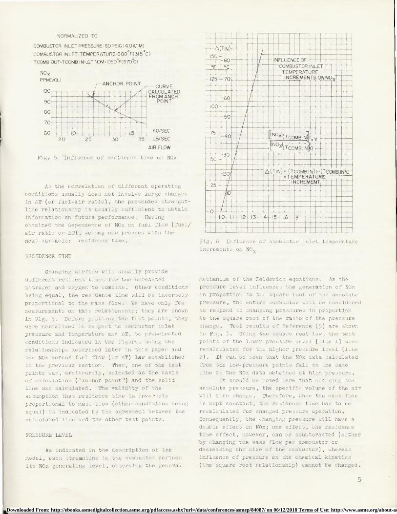
NORMALIZED TO
COMBUSTOR INLET PRESSURE: 60PSIG (4.OATM)
COMBUSTOR INLET TEMPERATURE 600`F(315 °C)
TCOMB.OUT-TCOMB.IN=LT NCM=1050'F(570 C)
NOXPPM(VOL)..■■■■■■■NR■■moil. • ■■■■■■■■■
_ ■
_ /.' ■
..■■■■■■■M■■■.J■■ ■■• ■■■■■■■ ■■■■^^^■■■NEON ■■■■■■■■oso'■■ ■ ■■■■■ ■N
•AIR FLOW
Fig, 5 Influence of residence time on NOx
As the correlation of different operating
conditions usually does not involve large changesin AT (or fuel-air ratio), the presented straight-line relationship is usually sufficient to obtaininformation on future performance, Having
obtained the dependence of NOx on fuel flow (fuel /air ratio or AT), we may now proceed with the
next variable: residence time.
RESIDENCE TIME
Changing airflow will usually provide
different resident times for the unreacted
nitrogen and oxygen to combine. Other conditions
being equal, the residence time will be inversely
proportional to the mass flow. We have only fewmeasurements on this relationship; they are shown
in Fig. 5. Before plotting the test points, theywere normalized in respect to combustor inletpressure and temperature and AT, to preselected
conditions indicated in the figure, using the
relationships described later in this paper and
the NOx versus fuel flow (or AT) law establishedin the previous section. Then, one of the testpoints was, arbitrarily, selected as the basisof calculation ("anchor point") and the solidline was calculated. The validity of the
assumption that residence time is inverselyproportional to mass flow (other conditions being
equal) is indicated by the agreement between the
calculated line and the other test points.
PRESSURE LEVEL
As indicated in the description of the
model, each streamline in the combustor defines
its NOx generating level, observing the general
■■■■■■■■■■■■■■■ ■■■■■■■■■■■■■■N■■■■■■■■. ■C•■■. ■■■■■■■■ ■N■■■■■^ ■^ •■•■■■■■■■•• : • •■■ _
■.•.••...••..
•■•■••v/■u•^/■•
•
• ■■■■■■■■•■••■• •a.•..•..• ■■■■■■■■N■■■■Kl■■■■
•• ■■■■//■■■ ■■■C■•■■■■►..•■•■•••■■•■••••••••••••••••••■m •■■■■•■■■■•■•■■ ••■M■■■■u■• ■■■■■
I■■ ■■ ■■■■■■■■■■■■■■■■■■ u■■u■■■■■■N■■■ii ■MMFAMM U•IUUUU•iiiiii
■■ M W1■■■■ • •
■
■■■■■■CI.■■■■ .■■■■■■■ I,■■■■■■ ■■■■■■
• r1■■N■■■■■■■■■■■■■■■■■■• ■■■■■■■■■■■■■I■■N■M■N■■N■■
■■.. ^C■■■■■NI^■■■■N■■■ •••■■isu muuuuurnuuuuuu•uuu•u•■L•••■•■•■■•■■•••■••■•■■■•■•i1•■■■■■■■•■•■•■■■■■■■■■■■•a■■■•■■■■■■■■■■■■■■■■■•■■
. ■%NNNNN■■■■■■■■■■■■
U■■■■■■■■■■■■■■■■■■■■ urn■■■■UFig, 6 Influence of combustor inlet temperature
increments on NO
mechanism of the Zeldovich equations, As thepressure level influences the generation of NOxin proportion to the square root of the absolute
pressure, the entire combustor will be considered
to respond to changing pressures in proportion
to the square root of the ratio of the pressure
change. Test results of Reference (5) are shown
in Fig. 3. Using the square root law, the testpoints of the lower pressure level (line 1) wererecalculated for the higher pressure level (line
2), It can be seen that the NOx data calculated
from the low-pressure points fall on the same
line as the NOx data obtained at high pressure.It should be noted here that changing the
absolute pressure, the specific volume of the airwill also change. Therefore, when the mass flow
is kept constant, the residence time has to be
recalculated for changed pressure operation.
Consequently, the changing pressure will have adouble effect on NOx; one effect, the residencetime effect, however, can be counteracted (eitherby changing the mass flow per combustor ordecreasing the size of the combustor), whereas
influence of pressure on the chemical kinetics
(the square root relationship) cannot be changed.
CURVELCULATEDOM ANCH.POINT
G/SECB/SEC
5
Downloaded From: http://ebooks.asmedigitalcollection.asme.org/pdfaccess.ashx?url=/data/conferences/asmep/84087/ on 06/12/2018 Terms of Use: http://www.asme.org/about-asme/terms-of-use
CULATEDANCHOR POINT
ISTEP AND'EBVRE(5)
R
POINT
0.7 0.8 0.9 1.0
EASURED
ALCULATED FROMNCHOR POINT
PCOMB. IN= COMBUSTOR INLETPRESSURE
PCOMB. IN(PCOMB IN)
ANCH. P
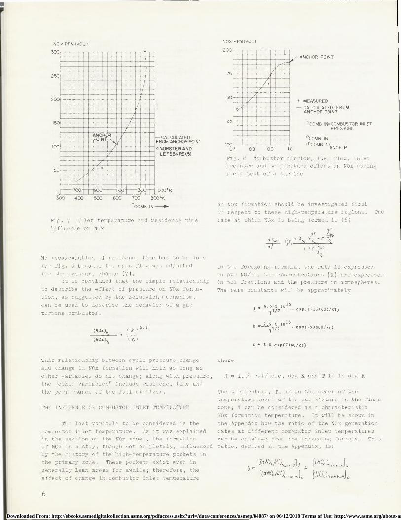
Fig, 8 Combustor airflow, fuel flow, inletpressure and temperature effect on NOx during
field test of a turbine
NOx PPM (VOL.) NOx PPM (VOL.)
TCOMB. IN —^
Fig, 7 Inlet temperature and residence time
influence on NOx
No recalculation of residence time had to be done
for Fig. 3 because the mass flow was adjusted
for the pressure change (7),It is concluded that the simple relationship
to describe the effect of pressure on NOx forma-tion, as suggested by the Zeldovich mechanism,
can be used to describe the behavior of a gas
turbine combustor:
(NOx),,' p 0.
(NOx) Pt
This relationship between cycle pressure change
and change in NOx formation will hold as long as
other variables do not change; along with pressure,the "other variables" include residence time andthe performance of the fuel atomizer,
THE INFLUENCE OF COMBUSTOR INLET TEMPERATURE
The last variable to be considered is the
combustor inlet temperature, As it was explainedin the section on the NOx model, the formationof NOx is mostly, though not completely, influenced
by the history of the high-temperature pockets inthe primary zone, These pockets exist even in
generally lean areas for awhile; therefore, the
effect of change in combustor inlet temperature
on NOx formation should be investigated firstin respect to these high-temperature regions, Therate at which NOx is being formed is (6)
as Ndx,, =1j4
1 QXN XOc—bx0idt + XN0
x01
In the foregoing formula, the rate is expressedin ppm NO/ms, the concentrations (X) are expressed
in mol fractions and the pressure in atmospheres.
The rate constants will be approximately
16• e-6 =T exp.(-134000/RT)
2.9 X 10b
15 exp(-90800/RT)^ TTJZ
c w 8.5 exp(7400/R7)
where
R = 1,98 cal/mole, deg K and T is in deg K
The temperature, T, is on the order of the
temperature level of the gas mixture in the flame
zone; T can be considered as a characteristic
NOx formation temperature, It will be shown in
the Appendix how the ratio of the NOx generationrates at different combustor inlet temperaturescan be obtained from the foregoing formula, Thisratio, derived in the Appendix, 15:
r(dN0„ ldt)T^^,+e.,^^1 r ^^ N^ *^rs. ,^^s
6
Downloaded From: http://ebooks.asmedigitalcollection.asme.org/pdfaccess.ashx?url=/data/conferences/asmep/84087/ on 06/12/2018 Terms of Use: http://www.asme.org/about-asme/terms-of-use
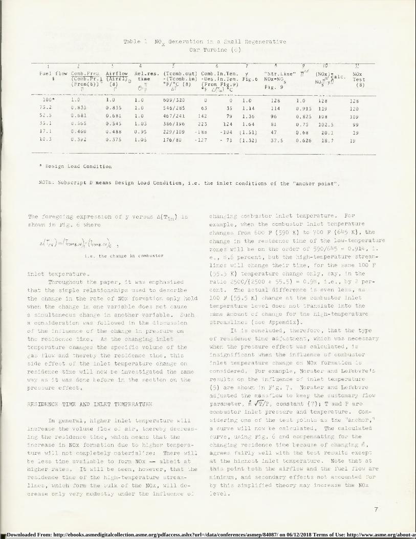
Table 1 NO Generation in a Small Regenerative
Car Turbine (8)
1 2 3 4 5 6 7 9 10 ,
Fuel flow Comb.Prez. Airflow Rel.res. (Tcomb.out) Comb.In.Tem. y "Str.Line"c
IT0. (NOx) NOx% om r. ar . time -(Tcomb.in) -Des.In.Tem. Fig.6 NOx-NOs
calc4 . Test(From(8)) D(8) IT °F/°C (8) (From Fi .9) NO.S )" (8)
TT I 0=^ AT OF i7) ^CFig. 9
100* 1.0 1.0 1.0 609/320 0 0 1.0 128 1.0 128 128
75.2 0.835 0.835 1.0 546/285 63 35 1.14 114 0.915 119 120
52.5 0.681 0.681 1.0 467/241 142 79 1.36 96 0.825 108 109
35.1 0.565 0.545 1.03 386/196 223 124 1.64 81 0.75 102.5 99
17.1 0.460 0.488 0.95 229/109 -188 -104 (1.51) 47 0.68 20.1 19
10.3 0.392 0.375 1.05 176/80 -127 - 71 (1.32) 37.5 0.626 18.7 19
* Design Load Condition
NOTE: Subscript D means Design Load Condition, i.e. the inlet conditions of the "anchor point".
The foregoing expression of y versus A(Tin ) isshown in Fig. 6 where
i.e. the change in combustor
inlet temperature.Throughout the paper, it was emphasized
that the simple relationships used to describe
the change in the rate of NOx formation only hold
when the change in one variable does not cause
a simultaneous change in another variable. Sucha consideration was followed in the discussion
of the influence of the change in pressure onthe residence time. As the changing inlet
temperature changes the specific volume of the
gas flow and thereby the residence time, thisside effect of the inlet temperature change on
residence time will now be investigated the sameway as it was done before in the section on thepressure effect.
RESIDENCE TIME AND INLET TEMPERATURE
In general, higher inlet temperature will
increase the volume flow of air, thereby decreas-ing the residence time, which means that theincrease in NOx formation due to higher tempera-
ture will not completely materialize: There will
be less time available to form NOx - albeit athigher rates. It will be seen, however, that the
residence time of the high-temperature stream-
lines, which form the bulk of the NOx, will de-
crease only very modestly under the influence of
changing combustor inlet temperature. For
example, when the combustor inlet temperature
changes from 600 F (59 0 K) to 700 F (645 K), the
change in the residence time of the low-temperaturezones will be on the order of 590/645 = 0,914, i,
e., 8.6 percent, but the high-temperature stream-
lines will change their time, for the same 100 F
(55 .5 K) temperature change only, say, in the
ratio 2500/(2500 + 55.5) = 0.98, i.e., by 2 per-cent. The actual difference is even less, as
100 F (55 .5 K) change at the combustor inlettemperature level does not translate into thesame amount of change for the high-temperature
streamlines (see Appendix),
It is concluded, therefore, that the typeof residence time adjustment, which was necessarywhen the pressure effect was calculated, isinsignificant when the influence of combustor
inlet temperature change on NOx formation is
considered. For example, Norster and Lefebvre's
results on the influence of inlet temperature
(5) are shown in Fig. 7. Norster and Lefebvre
adjusted the massflow to keep the customary flow
parameter, m/P, constant (7); T and P arecombustor inlet pressure and temperature. Con-
sidering one of the test points as the "anchor,"
a curve will now be calculated. The calculated
curve, using Fig. 6 and compensating for the
changing residence time because of changing m,agrees fairly well with the test results except
at the highest inlet temperature. Note that atthis point both the airflow and the fuel flow are
minimum, and secondary effects not accounted for
by this simplified theory may increase the NOx
level.
7
Downloaded From: http://ebooks.asmedigitalcollection.asme.org/pdfaccess.ashx?url=/data/conferences/asmep/84087/ on 06/12/2018 Terms of Use: http://www.asme.org/about-asme/terms-of-use
SOLID LINES CALCULATEDFROM BASELINE.ZERO °C ON AT SCALE
NO MADE TO MATCH ZERO ° FPPM(VOL)200 ■■■■■■■■
I5C
I•z•
5C
■■■■■■uuu uuu uN■■■■■■■ ■■■■■■■
iniiiiiii^ aim■MENI■MINE■.-••••■■••■•N•■■■■■•N••■■•■••_
; ^i^
.■N....
.:.^
■^.....WON.....■■■
•SEMEN■■■■■N■■■ ■
■^■■
nnnnnnnnn■IDS/^^^N^ nn•■■•■■ ■■■N■■■■■^1/^a^^■■ ■■ON^^^
U •• •• U •••to••
•••:
■■■■̂■■■■̂■■■■■■■■■■■■■■■ • • - ■■■■
■■EN■ ■icennnnn nnnnn• ' " • ■MI■■■^■■■■■■■■■■'■■■■■■ ■■■■■■N^^■■■■
•■■•■■•■■■•■•^■■•■■■■•••■■■■■■■■■■■
u• ■
^. '■■■MONO■.
M■■■■■ ■■■■■^nnnnnn • • : - OMEN■■■n I'■■■■MINE■■■■ ■■■■■■■■'::::::::::'
■N
•• IMEMEMu■■■■■ •-, • • •
• ' ■iii• ■■■■■
C.■iC:!■■■■■ ■■••••••••••••u••!■■■■■■■■ ■
n nn
-
- • .- -
■■■■ innnnnnnnnnn
NEM■■■■■ ■■ ■ ■SENSE
■■■■■■■■■■■I■■■■■■■N ■■■■■■■■
■■■• • =
■■■■■■■■■■■■■■'.■■■ ■■■■■■■■■■■■■■■■ ■■■■■■■■■N■■■ME■ ■■■■■■■ ■■■■ ■■■■■■■■ ■■■■■■■■
■U■^^'■■ MEMO ■■■■■■ ■■•■■■
■ • nnnnnnn • • nnnnnn • • • '^,.■■■■■■■■■I ^_
Vv1 v 1 VVIv II.A 11•
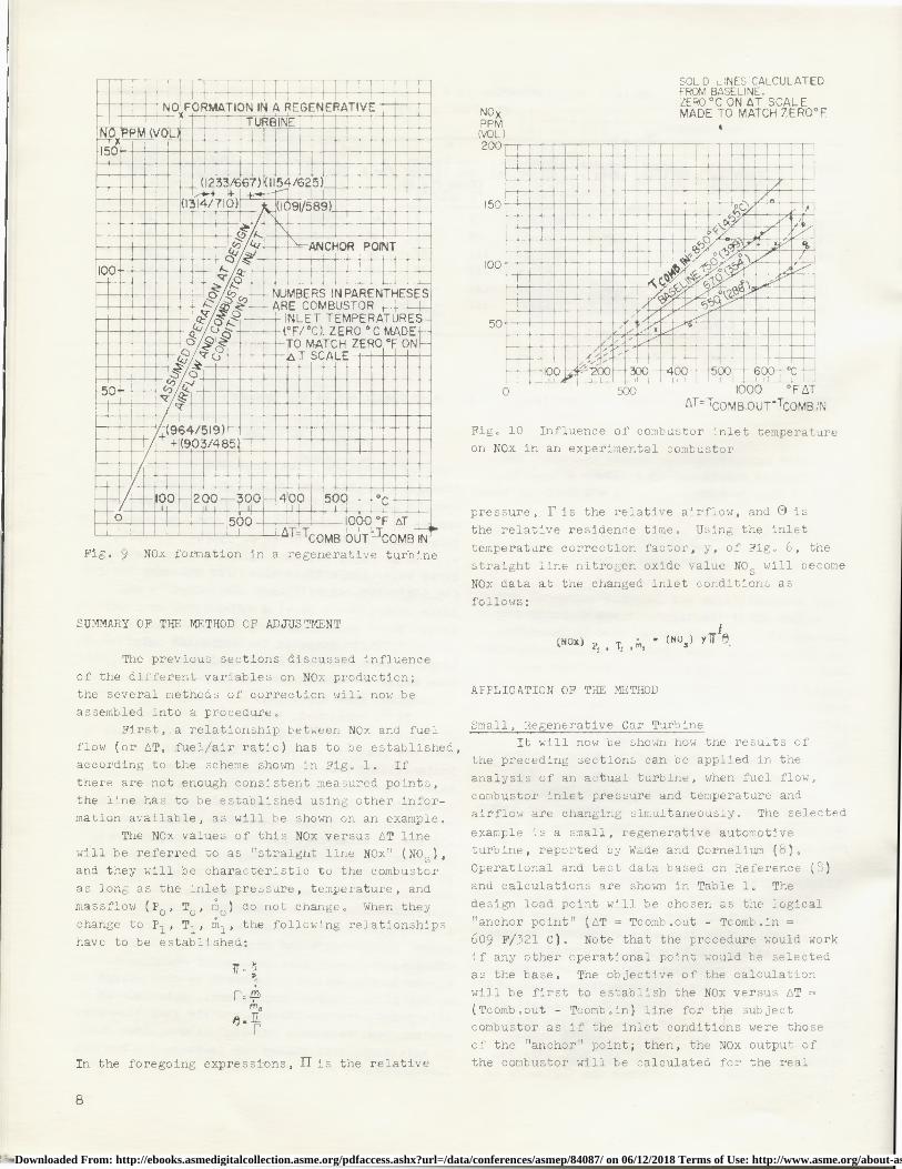
Fig, 9 NOx formation in a regenerative turbine
U ouu ww r eAT= TCOMB.OUT-TCOMB IN
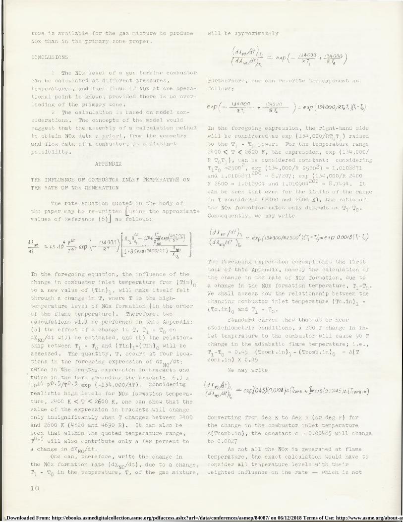
Fig, 10 Influence of combustor inlet temperatureon NOx in an experimental combustor
pressure, Pis the relative airflow, and O is
the relative residence time. Using the inlet
temperature correction factor, y, of Fig, 6, the
straight line nitrogen oxide value NO s will become
NOx data at the changed inlet conditions as
follows:
SUMMARY OF THE METHOD OF ADJUSTMENT
The previous sections discussed influence
of the different variables on NOx production;the several methods of correction will now be
assembled into a procedure.
First, a relationship between NOx and fuelflow (or AT, fuel/air ratio) has to be established,according to the scheme shown in Fig. 1. If
there are not enough consistent measured points,
the line has to be established using other infor-mation available, as will be shown on an example.
The NOx values of this NOx versus AT linewill be referred to as "straight line NOx" (NO S ),and they will be characteristic to the combustor
as long as the inlet pressure, temperature, andmassflow (Po , To , m o ) do not change. When theychange to P 1 , T1 , ml , the following relationshipshave to be established:
Tr F
m,
In the foregoing expressions, II is the relative
(NOx) p' , T^ (NOS) YTr {8
APPLICATION OF THE METHOD
Small, Regenerative Car TurbineIt will now be shown how the results of
the preceding sections can be applied in the
analysis of an actual turbine, when fuel flow,
combustor inlet pressure and temperature andairflow are changing simultaneously. The selected
example is a small, regenerative automotiveturbine, reported by Wade and Cornelium (8),
Operational and test data based on Reference (8)
and calculations are shown in Table 1. The
design load point will be chosen as the logical
"anchor point" (AT = Tcomb.out - Tcomb,in =609 F/321 C). Note that the procedure would workif any other operational point would be selectedas the base. The objective of the calculation
will be first to establish the NOx versus AT =
(Tcomb,out - Tcomb.in) line for the subjectcombustor as if the inlet conditions were those
of the "anchor" point; then, the NOx output ofthe combustor will be calculated for the real
8
Downloaded From: http://ebooks.asmedigitalcollection.asme.org/pdfaccess.ashx?url=/data/conferences/asmep/84087/ on 06/12/2018 Terms of Use: http://www.asme.org/about-asme/terms-of-use

inlet conditions and compared with the test data.
The line containing the "anchor point"
will be obtained as follows:
As a first approximation, we assume that
the reference velocity, i.e., the residence time
in the combustor, does not change significantlyfor the various load points. (This assumptionwill have to be verified later.) If we adjustthe test data of Reference (8) for pressure
(using the square root law), we obtain approximate
NOx values which would be comparable with the
"anchor point" data except for the inlet tempera-ture effect, These pressure adjusted NOx data areshown in Fig. 9. The figure also shows the inlettemperatures for the test points (8). The
straight line containing the "anchor point" will
have to run below the points that have a higher
inlet temperature than the "anchor point" andabove those points which have a lower inlet
temperature. We also know that the line through
the anchor point cannot have a positive intercept
with the vertical axis because this would mean
NOx production at zero AT (i.e., zero fuel flow).
Inspection of Fig. 9 indicates that to satisfy
the aforementioned restrictions, the NOx versusAT line for the "anchor point" conditions has torun across the origin. Now we can turn to thetask of calculating the actual test data from the
straight line established in the foregoing and
the operational conditions of Table 1 and compare
the results with the NOx data of Reference (8),
shown in Table 1, Column 11.Consider, for example, the 35.1 percent fuel
flow point in Table 1. According to Reference
(8), the speed of the turbine is 70 percent of
the design speed at this point, and the airflowdrops to 54.5 percent of the airflow at design
load conditions (anchor point): enter IF = 0.545
in column 3. The cycle pressure also decreases,from 3.68 atm-abs (54 psia) to 2.06 atm-abs(30.6 psia): enter II = 0 .565 in column 2. Theratio 0.565/0.545 yields the relative residence
time, 0 =11/F= 1.03 (column 4). (Note that the
numbers in column 4 substantiate the assumption
made before [when the straight line NOx versus
AT going through the "anchor point" was estab-lished) that the residence time does not change
significantly at different points of operation
of the turbine.)
We next establish the temperature rise in
the combustor, from data in Reference (8): 386
F/196 C and enter this in column 5. Operationaldata (8) yield the combustor inlet temperature
for AT = 386 F/196 C: Tcombustor in = 1314 F/710 C, which yields A(Tin) = 1314 - 1091 = 223 F
(124 C) to be entered in column 6.
The next step is to obtain y from 6, at
A(Tin) = 223 F (124 C). The figure was not
calculated beyond 150 F where y = 1.38. We maywrite, however,
Therefore, Y223 F = Y150 F ` y73 F = 1 .38 x 1.18= 1.64 (column 7). We now read the "straight
line NOx" from Fig. 9 (81 ppm), enter it in
column 8, then calculate IIz from column 2 (0.75),
enter it in column 9 and now we can calculate theNOx for the changed conditions:
(NUX) p! • Tj • m^ • NUS
$1 x 0.7$ z 1.64 x 1.03 • 102.5 pp.
This calculated value compares quite well with
the test value from Reference (8) in column 11:
99 ppm.
ANALYSIS OF FIELD TEST
The results of the previous sections were
applied to an industrial gas turbine of the
author's company. The turbine is equipped with
compressor inlet guide vanes; closing of the
vanes reduces the mass flow and decreases thecombustor pressure and temperature. The turbineinlet temperature was kept constant; therefore,
the temperature rise across the combustor changed.
NOx was measured for the nominal opening ofthe guide vanes ("anchor point") and at fourdifferent pressure levels as shown in Fig. 8.
NOx was calculated for these operating conditionsas in Table 1 (Fig. 8, solid line). It can be
seen that the measured NOx values compare fairly
well with the calculated curve.
INLET TEMPERATURE EFFECT IN AN EXPERIMENTAL
COMBUSTOR
The NOx performance of an experimental
combustor is shown in Fig. 10. The family of
straight lines was calculated on the basis of
the 750 F (399 C) line, using the method shownin Fig. 6. It can be seen that the "third modeof operation" (upswing) is most pronounced atlow combustor inlet temperature, then gradually
disappears as the inlet temperature increases.
It is believed that the increasing temperature
level at the entry of the spray promotes fastervaporization of the droplets resulting in fewerdroplets escaping from the primary zone into the
downstream end of the combustor where there isless mixing; therefore, more time at high tempera-
9
Downloaded From: http://ebooks.asmedigitalcollection.asme.org/pdfaccess.ashx?url=/data/conferences/asmep/84087/ on 06/12/2018 Terms of Use: http://www.asme.org/about-asme/terms-of-use
ture is available for the gas mixture to produce
NOx than in the primary zone proper.
CONCLUSIONS
1 The NOx level of a gas turbine combustorcan be calculated at different pressures,
temperatures, and fuel flows if NOx at one opera-
tional point is known, provided there is no over-
loading of the primary zone.2 The calculation is based on model con-
siderations. The concepts of the model wouldsuggest that the assembly of a calculation method
to obtain NOx data a priori, from the geometry
and flow data of a combustor, is a distinct
possibility.
APPENDIX
THE INFLUENCE OF COMBUSTOR INLET TEMPERATURE ON
THE RATE OF NOx GENERATION
The rate equation quoted in the body of
the paper may be re-written [using the approximatevalues of Reference (6)] as follows:
will be approximately
Pxp /_ '34000 + i 34000 1^ XNO%Il)To ` xT PT, /
Furthermore, one can re-write the exponent asfollows:
PY ^ r 131,000 134030
` 7 t — )°exp(134000/RT,T,1YT,-)0
In the foregoing expression, the right-hand side
will be considered as exp (134,000/RT OT1 ) raisedto the T1 - TO power. For the temperature range
2400 < T < 2600 K, the expression, exp (134,000/
R TOT1 ), can be considered constant: consideringT1T0 =2500 2 , exp (134,000/R 25002 ) = 1.0108871and 1.0108871200 = 8.7207; exp (134,000/R 2400X 2600 = 1.010904 and 1.010904200 = 8.7494. It
can be seen that even for the limits of the range
in T considered (2400 and 2600 K), the ratio of
the NOx formation rates only depends on T 1 -T0 .
Consequently, we may write
` X,a p 4- 4̂ 0 'd 410K Pns (_ 134o0fl1 X '^ X4
-0046 X ^ex ' K' ^dX ^/?1 170
^x^i^13ti000/RlSoos)^^-T^^^exp 0.00^8(^" ^^
eX \ Jdt ra P Rr
I1+&5exp(7400^aT)X 1
In the foregoing equation, the influence of the
change in combustor inlet temperature from (Tin) 0
to a new value of (Tin),, will make itself felt
through a change in T, where T is the high-
temperature level of NOx formation (in the order
of the flame temperature). Therefore, two
calculations will be performed in this Appendix:(a) the effect of a change in T, T 1 - TO on
dXNO/dt will be estimated, and (b) the relation-
ship between T1 - TO and (Tin) 1 -(Tin) 0 will be
assessed. The quantity, T, occurs at four loca-
tions in the foregoing expression of dX NO/dt:
twice in the lengthy expression In brackets anO
twice in the term preceding the bracket: 6.3 x10¹⁶ P0.5/T0.5 exp (-134,000/RT). Considering
realistic high levels for NOx formation tempera-
ture, 2400 K < T < 2600 K, one can show that the
value of the expression in brackets will change
only insignificantly when T changes between 2400and 2600 K (4320 and 4690 R). It can also be
seen that within the quoted temperature range,
TO ° 5 will also contribute only a few percent toa change in dX NO/dt.
One can, therefore, write the change in
the NOx formation rate (dXNO/dt), due to a change,T1 - TO in the temperature, T, of the gas mixture,
The foregoing expression accomplishes the first
task of this Appendix, namely the calculation of
the change in the rate of NOx formation, due to
a change in the NOx formation temperature, T 1 -T0 .We shall assess now the relationship between the
changing combustor inlet temperature (Tc,in) 1 -(Tc.in) 0 and T1 - T0 .
Standard curves show that at or near
stoichiometric conditions, a 200 F change in in-
let temperature to the combustor will cause 90 F
change in the adiabatic flame temperature; i.e.,
T1 -TO = 0.45 (Tcomb.in) 1 - (Tcomb.in) 0 = A(Tcomb.in ) X 0.45
We may write
(/X df)TO exr Q45)( .olod a(T-o , e p(aoo4s5)o(r0, ,,.)
Converting from deg K to deg R (or deg F) forthe change in the combustor inlet temperature
0(Tcomb.in), the constant c = 0.00485 will change
to 0.0027
As not all the NOx is generated at flametemperature, the exact calculation would have toconsider all temperature levels with theirweighted influence on the rate — which is not
10
Downloaded From: http://ebooks.asmedigitalcollection.asme.org/pdfaccess.ashx?url=/data/conferences/asmep/84087/ on 06/12/2018 Terms of Use: http://www.asme.org/about-asme/terms-of-use
the purpose of the approximate method described
here. Analysis of test results showed that using
an "effective" Ceff <C = 0.0027, one should use
0.00224 instead of 0.0027:
(d XN0 ^()(rrcw,e . in )^ ^^NJ^r ^or,•b. l„)d
('Ci AM, ,d! )( 7ra , i. . (X NO )(Tron^b. ")o
where Tcom.in is in deg F. The function, y,
is shown in Fig. 6.
ACKNOWLEDGMENTS
The writer would like to thank for the
help, encouragement and constructive criticism
of his colleagues, especially M. J. Ambrose, S.
M. DeCorso, W. S. Y. Hung, C. E. Hussey, andS. S. Lin,
REFERENCES
1 Carl, D. E., "The Influence of Ambient
Humidity on Nitric Oxide Generation,” Gas Turbine
International, Vol. 15, No. 3, May-June 1974,pp. 28-32.
2 Marteney, P. J., "Analytical Study ofthe Kinetics of Formation of Nitrogen Oxide inHydrocarbon-Air Combustion," Combustion Science
and Technology, Vol. 1, 1970, pp. 461-469.
3 Zeldovich, Ya, B., Sadornikov, P. Ya.
and Frank-Kamenetskii, D. A., "Oxidation of
Nitrogen in Combustion," Academy of Sciences ofthe USSR, Institute of Chemical Physics, Moscow-Leningrad, 1947 (translations by M. Shelef),
4 Breton, R. A., Koblish, T. R., and
Marshall, R. L., "Design and Test Limitations on
Reducing NOx in Gas Turbine Combustors," SAE
Paper 740182, Society of Automotive Engineers,Inc., New York, 1974.
5 Norster, E. R. and Lefebvre, A. H.,"Effects of Fuel Injection Method on Gas Turbine
Combustor Emissions," Proceedings of the Symposium
on Emissions from Continuous Combustion Systems,General Motors Research Laboratories, Warren,
Mich., Sept. 1971, Plenum Press, 1 97 2 , pp. 2 55-278.
6(a) Wolfrum, J., Chemie Ing, Technik,
Vol. 44, 1972 , p. 656 ; (b) Stull, D. K., ed.,
JANAF Thermochemical Tables, Dow Chemical
Company, Midland, Mich., 1971.
7 Norster, E. R., verbal communication to
G. Vermes, 1974.8 Wade, W. R. and Cornelius, W., "Emission
Characteristics of Continuous Combustion Systemsof Vehicular Powerplants," Proceedings of the
Symposium on Emissions from Continuous Combustion
Systems, General Motors Research Laboratories,
Warren, Mich., Sept. 1971, Plenum Press, 1972,
pp . 375-445.
11
Downloaded From: http://ebooks.asmedigitalcollection.asme.org/pdfaccess.ashx?url=/data/conferences/asmep/84087/ on 06/12/2018 Terms of Use: http://www.asme.org/about-asme/terms-of-use