Embed Size (px)
Citation preview
8/17/2019 OX Assembly Manual
http://slidepdf.com/reader/full/ox-assembly-manual 1/44OX CNC 1
OX CNCAssembly Instructions
8/17/2019 OX Assembly Manual
http://slidepdf.com/reader/full/ox-assembly-manual 2/44OX CNC 2
Table of Contents
1.0 Getting Started 3
1.1 About The Kit 4
1.2 Check Product Contents 4
2.0 Assembly 6
2.1 Wheel Assembly 72.2 Side Plates 8
2.2.2 Wheel & Brace Assembly.............................................................. 9
2.3 X-Carriage Assembly 11
2.3.2 Front Plate Wheel Assembly Part 1 .............................................. 122.3.3 Front Plate Wheel Assembly Part 2 .............................................. 132.3.4 Attaching Back Plate Motor......................................................... 142.3.5 Mating Front & Back Plates......................................................... 15
2.4 Z Axis Assembly 17
2.4.2 Attaching V-Slot........................................................................ 182.4.3 Attaching ACME-Lead-Screw....................................................... 192.4.4 Threaded-Rod-Mount-Bottom...................................................... 20
2.5 X Gantry Assembly 21
2.5.2 Tee-Nuts & Carriage .................................................................. 222.5.3 Angle-Corners .......................................................................... 23
2.6 Base Assembly 24
2.6.2 Y-End-Plates............................................................................. 252.6.3 V-Slot Positioning - 2 ................................................................. 272.6.4 Y-End-Plates - Final Bolts ........................................................... 282.6.5 Angle-Corners .......................................................................... 292.6.6 Spoiler Board Support - 1 .......................................................... 302.6.7 Spoiler Board Support - 2 .......................................................... 312.6.8 End-Caps................................................................................. 32
2.7 GT3-Pulley & Belt Assembly 33
2.7.2 Tee-Nuts.................................................................................. 342.7.3 GT3-Timing-Belt ....................................................................... 352.7.4 Securing the GT3-Timing-Belt ..................................................... 362.7.5 Repeat .................................................................................... 37
2.8 Face-Plate 38
2.9 Complete 39
3.0 Appendix 40
3.1 Appendix A - Kit Contents 41

8/17/2019 OX Assembly Manual
http://slidepdf.com/reader/full/ox-assembly-manual 3/44OX CNC Getting Started 3
1.0 GettingStarted
8/17/2019 OX Assembly Manual
http://slidepdf.com/reader/full/ox-assembly-manual 4/44OX CNC Getting Started 4
1.1 About The Kit
The ooznest OX CNC Machine Kit is based on the OX CNC Machine designed by Mark Carewof Openbuilds (http://www.openbuilds.com/builds/openbuilds-ox-cnc-machine.341/), and in-corporates many upgrades from the Openbuilds community. Mark Carew based the OX on theRouty, which was in turn based on the Shapeoko. The OX CNC Machine uses the excellent V-Slot Extrusion, which provides a strong, smooth, and accurate linear motion system.
We would like to give a big thank you to Mark Carew and Openbuilds for designing an excel-lent CNC Machine and V-Slot system, which they have allowed to be freely shared, remixed,and sold. We would also like to thank the Openbuilds and wider community for sharing theirupgrades to make the OX even better.
1.2 Check Product Contents
The first thing you should do when you receive your kit is to check the contents against thelist in Appendix A. For small parts, a few more spare is included than the quantity shown in
Appendix A. If anything is missing or damaged or you have any other problems, please con-tact us at [email protected], and we will aim to resolve the issue as quickly as possible.
1.3 Tools Required
The list below shows the main tools that will be required to complete this build:
• 1.5mm Allen key (Provided)
• 2.5mm Allen key
• 4mm Allen key
• 8mm spanner
• 10mm spanner
1.4 Notes on Assembly
It is recommended that you read through the whole manual before beginning the build. Thisis so you can get a rough idea of how it all goes together. Before starting each step make sureyou have studied the diagram and fully understand what you are doing at each step. The PDF
version of the manual is available on our website. Use it if needed. This will allow you to zoomin on the diagrams.
This instruction manual follows Mark Carew’s build videos on the Openbuilds website. Use hisvideos if needed to gain a different look into each step. The videos can be found at: http://www.openbuilds.com/builds/openbuilds-ox-cnc-machine.341/
When attaching parts, make sure they are sensibly squared and aligned. Everything shouldeasily fit together. If a part is requiring significant force to attach, then stop, take it off, re-read the instructions, and try again. Do not overtighten bolts, as you may strip the threads.
If you forgot to insert a Tee-Nut when instructed, there is no need to worry or undo any ofthe work you have done. In the kit we have included 5 x M5-Drop-In-Tee-Nuts for this situa-tion. These M5-Drop-In-Tee-Nuts do not have to be inserted from the end of the extrusion.

8/17/2019 OX Assembly Manual
http://slidepdf.com/reader/full/ox-assembly-manual 5/44OX CNC Getting Started 5
Simply place them in the V-Slot, then screw in the bolt which will turn them and engagethem into the underside of the V-Slot.

8/17/2019 OX Assembly Manual
http://slidepdf.com/reader/full/ox-assembly-manual 6/44OX CNC Assembly 6
2.0 Assembly
8/17/2019 OX Assembly Manual
http://slidepdf.com/reader/full/ox-assembly-manual 7/44OX CNC Assembly 7
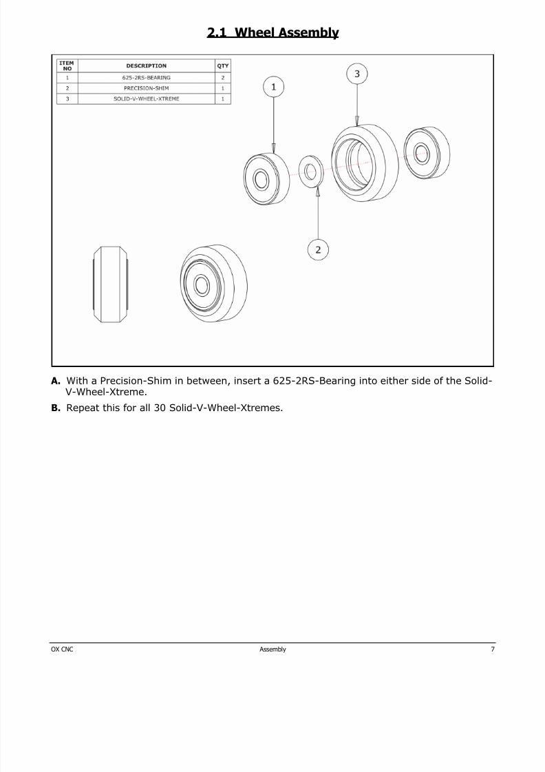
2.1 Wheel Assembly
A. With a Precision-Shim in between, insert a 625-2RS-Bearing into either side of the Solid-V-Wheel-Xtreme.
B. Repeat this for all 30 Solid-V-Wheel-Xtremes.
8/17/2019 OX Assembly Manual
http://slidepdf.com/reader/full/ox-assembly-manual 8/44OX CNC Assembly 8
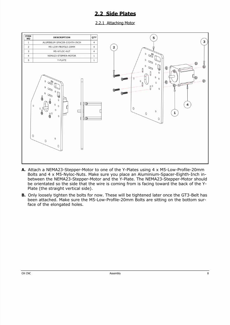
2.2 Side Plates
2.2.1 Attaching Motor
A. Attach a NEMA23-Stepper-Motor to one of the Y-Plates using 4 x M5-Low-Profile-20mmBolts and 4 x M5-Nyloc-Nuts. Make sure you place an Aluminium-Spacer-Eighth-Inch in-between the NEMA23-Stepper-Motor and the Y-Plate. The NEMA23-Stepper-Motor shouldbe orientated so the side that the wire is coming from is facing toward the back of the Y-Plate (the straight vertical side).
B. Only loosely tighten the bolts for now. These will be tightened later once the GT3-Belt has
been attached. Make sure the M5-Low-Profile-20mm Bolts are sitting on the bottom sur-face of the elongated holes.
8/17/2019 OX Assembly Manual
http://slidepdf.com/reader/full/ox-assembly-manual 9/44OX CNC Assembly 9
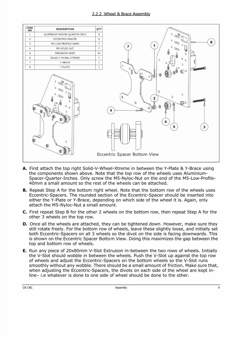
2.2.2 Wheel & Brace Assembly
A. First attach the top right Solid-V-Wheel-Xtreme in between the Y-Plate & Y-Brace usingthe components shown above. Note that the top row of the wheels uses Aluminium-Spacer-Quarter-Inches. Only screw the M5-Nyloc-Nut on the end of the M5-Low-Profile-40mm a small amount so the rest of the wheels can be attached.
B. Repeat Step A for the bottom right wheel. Note that the bottom row of the wheels usesEccentric-Spacers. The rounded section of the Eccentric-Spacer should be inserted intoeither the Y-Plate or Y-Brace, depending on which side of the wheel it is. Again, onlyattach the M5-Nyloc-Nut a small amount.
C. First repeat Step B for the other 2 wheels on the bottom row, then repeat Step A for theother 3 wheels on the top row.
D. Once all the wheels are attached, they can be tightened down. However, make sure theystill rotate freely. For the bottom row of wheels, leave these slightly loose, and initially setboth Eccentric-Spacers on all 3 wheels so the divot on the side is facing downwards. Thisis shown on the Eccentric Spacer Bottom View. Doing this maximizes the gap between thetop and bottom row of wheels.
E. Run any piece of 20x80mm V-Slot Extrusion in-between the two rows of wheels. Initiallythe V-Slot should wobble in between the wheels. Push the V-Slot up against the top row
of wheels and adjust the Eccentric-Spacers on the bottom wheels so the V-Slot runssmoothly without any wobble. There should be a small amount of friction. Make sure that,when adjusting the Eccentric-Spacers, the divots on each side of the wheel are kept in-line– i.e whatever is done to one side of wheel should be done to the other.
8/17/2019 OX Assembly Manual
http://slidepdf.com/reader/full/ox-assembly-manual 10/44OX CNC Assembly 10
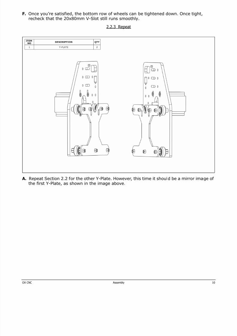
F. Once you’re satisfied, the bottom row of wheels can be tightened down. Once tight,recheck that the 20x80mm V-Slot still runs smoothly.
2.2.3 Repeat
A. Repeat Section 2.2 for the other Y-Plate. However, this time it should be a mirror image ofthe first Y-Plate, as shown in the image above.
8/17/2019 OX Assembly Manual
http://slidepdf.com/reader/full/ox-assembly-manual 11/44OX CNC Assembly 11
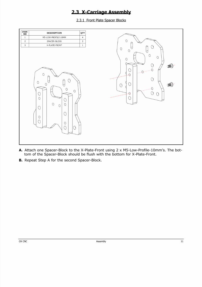
2.3 X-Carriage Assembly
2.3.1 Front Plate Spacer Blocks
A. Attach one Spacer-Block to the X-Plate-Front using 2 x M5-Low-Profile-10mm’s. The bot-tom of the Spacer-Block should be flush with the bottom for X-Plate-Front.
B. Repeat Step A for the second Spacer-Block.
8/17/2019 OX Assembly Manual
http://slidepdf.com/reader/full/ox-assembly-manual 12/44OX CNC Assembly 12
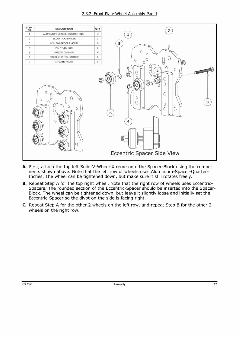
2.3.2 Front Plate Wheel Assembly Part 1
A. First, attach the top left Solid-V-Wheel-Xtreme onto the Spacer-Block using the compo-nents shown above. Note that the left row of wheels uses Aluminium-Spacer-Quarter-Inches. The wheel can be tightened down, but make sure it still rotates freely.
B. Repeat Step A for the top right wheel. Note that the right row of wheels uses Eccentric-Spacers. The rounded section of the Eccentric-Spacer should be inserted into the Spacer-Block. The wheel can be tightened down, but leave it slightly loose and initially set theEccentric-Spacer so the divot on the side is facing right.
C. Repeat Step A for the other 2 wheels on the left row, and repeat Step B for the other 2wheels on the right row.
8/17/2019 OX Assembly Manual
http://slidepdf.com/reader/full/ox-assembly-manual 13/44OX CNC Assembly 13
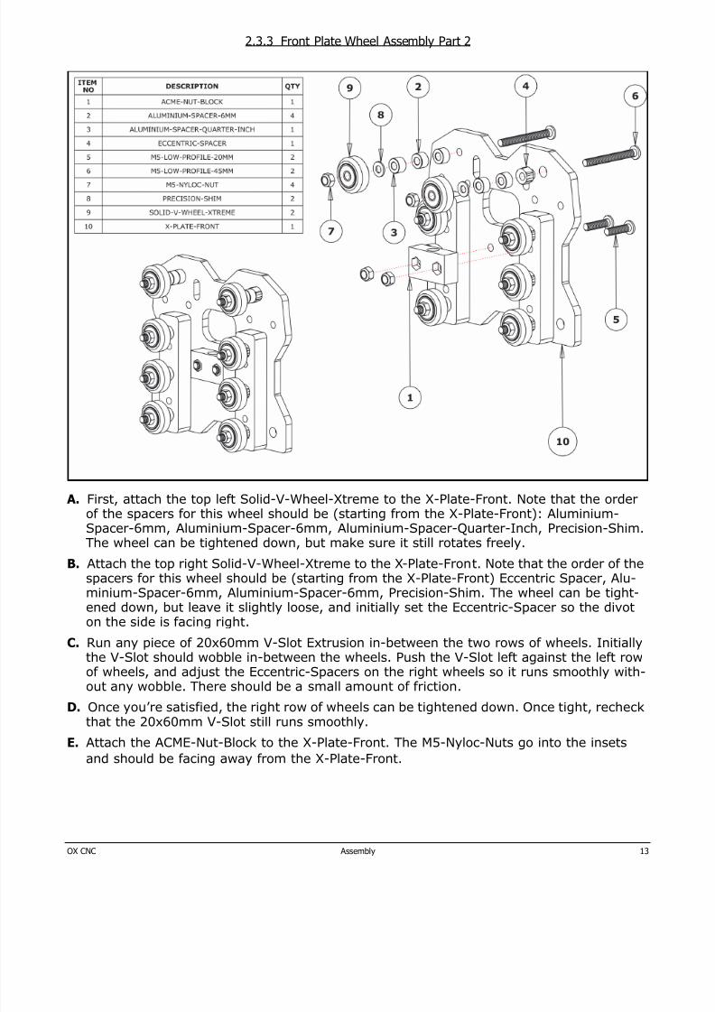
2.3.3 Front Plate Wheel Assembly Part 2
A. First, attach the top left Solid-V-Wheel-Xtreme to the X-Plate-Front. Note that the orderof the spacers for this wheel should be (starting from the X-Plate-Front): Aluminium-Spacer-6mm, Aluminium-Spacer-6mm, Aluminium-Spacer-Quarter-Inch, Precision-Shim.The wheel can be tightened down, but make sure it still rotates freely.
B. Attach the top right Solid-V-Wheel-Xtreme to the X-Plate-Front. Note that the order of thespacers for this wheel should be (starting from the X-Plate-Front) Eccentric Spacer, Alu-minium-Spacer-6mm, Aluminium-Spacer-6mm, Precision-Shim. The wheel can be tight-ened down, but leave it slightly loose, and initially set the Eccentric-Spacer so the divot
on the side is facing right.
C. Run any piece of 20x60mm V-Slot Extrusion in-between the two rows of wheels. Initiallythe V-Slot should wobble in-between the wheels. Push the V-Slot left against the left rowof wheels, and adjust the Eccentric-Spacers on the right wheels so it runs smoothly with-out any wobble. There should be a small amount of friction.
D. Once you’re satisfied, the right row of wheels can be tightened down. Once tight, recheckthat the 20x60mm V-Slot still runs smoothly.
E. Attach the ACME-Nut-Block to the X-Plate-Front. The M5-Nyloc-Nuts go into the insets
and should be facing away from the X-Plate-Front.
8/17/2019 OX Assembly Manual
http://slidepdf.com/reader/full/ox-assembly-manual 14/44OX CNC Assembly 14
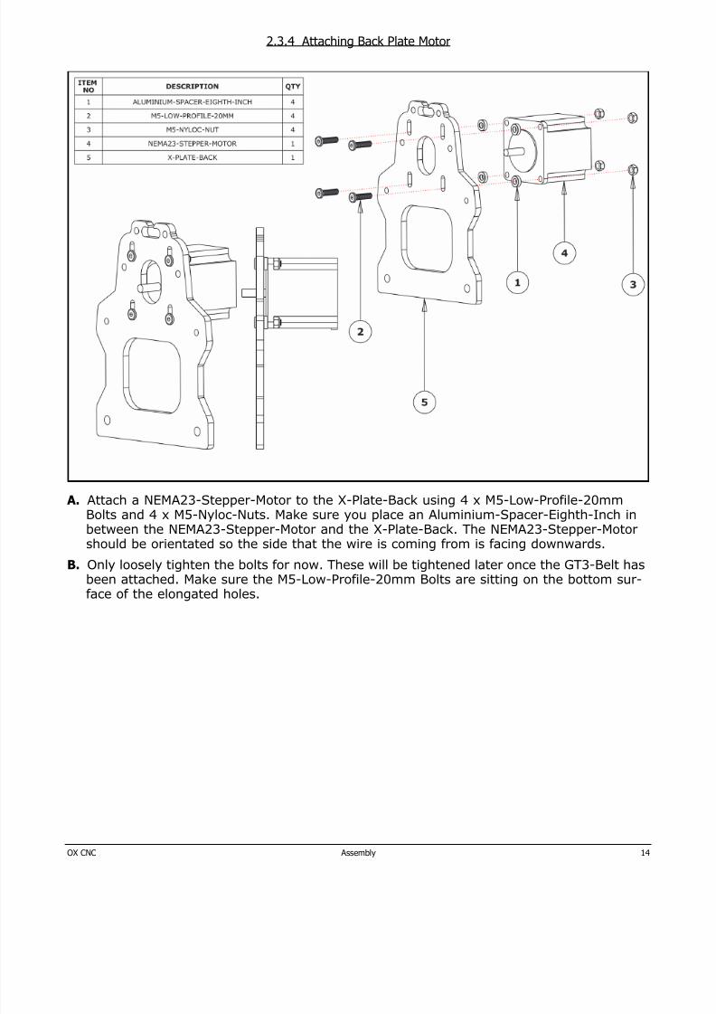
2.3.4 Attaching Back Plate Motor
A. Attach a NEMA23-Stepper-Motor to the X-Plate-Back using 4 x M5-Low-Profile-20mmBolts and 4 x M5-Nyloc-Nuts. Make sure you place an Aluminium-Spacer-Eighth-Inch inbetween the NEMA23-Stepper-Motor and the X-Plate-Back. The NEMA23-Stepper-Motorshould be orientated so the side that the wire is coming from is facing downwards.
B. Only loosely tighten the bolts for now. These will be tightened later once the GT3-Belt hasbeen attached. Make sure the M5-Low-Profile-20mm Bolts are sitting on the bottom sur-face of the elongated holes.
8/17/2019 OX Assembly Manual
http://slidepdf.com/reader/full/ox-assembly-manual 15/44OX CNC Assembly 15
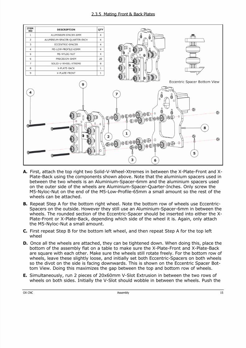
2.3.5 Mating Front & Back Plates
A. First, attach the top right two Solid-V-Wheel-Xtremes in between the X-Plate-Front and X-Plate-Back using the components shown above. Note that the aluminium spacers used inbetween the two wheels is an Aluminium-Spacer-6mm and the aluminium spacers usedon the outer side of the wheels are Aluminium-Spacer-Quarter-Inches. Only screw theM5-Nyloc-Nut on the end of the M5-Low-Profile-65mm a small amount so the rest of thewheels can be attached.
B. Repeat Step A for the bottom right wheel. Note the bottom row of wheels use Eccentric-Spacers on the outside. However they still use an Aluminium-Spacer-6mm in between the
wheels. The rounded section of the Eccentric-Spacer should be inserted into either the X-Plate-Front or X-Plate-Back, depending which side of the wheel it is. Again, only attachthe M5-Nyloc-Nut a small amount.
C. First repeat Step B for the bottom left wheel, and then repeat Step A for the top leftwheel
D. Once all the wheels are attached, they can be tightened down. When doing this, place thebottom of the assembly flat on a table to make sure the X-Plate-Front and X-Plate-Backare square with each other. Make sure the wheels still rotate freely. For the bottom row ofwheels, leave these slightly loose, and initially set both Eccentric-Spacers on both wheelsso the divot on the side is facing downwards. This is shown on the Eccentric Spacer Bot-tom View. Doing this maximizes the gap between the top and bottom row of wheels.
E. Simultaneously, run 2 pieces of 20x60mm V-Slot Extrusion in between the two rows ofwheels on both sides. Initially the V-Slot should wobble in between the wheels. Push the

8/17/2019 OX Assembly Manual
http://slidepdf.com/reader/full/ox-assembly-manual 16/44OX CNC Assembly 16
V-Slot up against the top row of wheels and adjust the Eccentric-Spacers on the bottomwheels so the V-Slot runs smoothly without any wobble. There should be a small amountof friction. Make sure that, when adjusting the Eccentric-Spacers, the divots on each sideof the two wheels are kept in-line where possible– i.e whatever is done to one side shouldbe done to the other.
F. Once satisfied, the bottom row of wheels can be tightened down. Once tight, recheck that
2 x 20x60mm V-Slot still runs smoothly.
8/17/2019 OX Assembly Manual
http://slidepdf.com/reader/full/ox-assembly-manual 17/44OX CNC Assembly 17
2.4 Z Axis Assembly
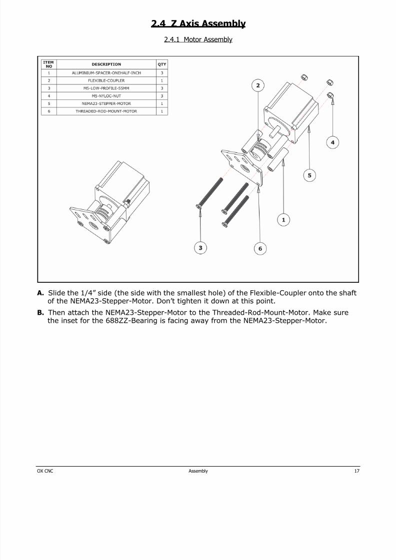
2.4.1 Motor Assembly
A. Slide the 1/4” side (the side with the smallest hole) of the Flexible-Coupler onto the shaftof the NEMA23-Stepper-Motor. Don’t tighten it down at this point.
B. Then attach the NEMA23-Stepper-Motor to the Threaded-Rod-Mount-Motor. Make surethe inset for the 688ZZ-Bearing is facing away from the NEMA23-Stepper-Motor.

8/17/2019 OX Assembly Manual
http://slidepdf.com/reader/full/ox-assembly-manual 18/44OX CNC Assembly 18
2.4.2 Attaching V-Slot
A. Attach the V-Slot-2060-200mm to the Threaded-Rod-Mount-Motor using 3 x M5-Low-Pro-file-10mm. For the middle bolt, the short end of the Allen key may need to be used. Leavethese bolts initially loose so the Threaded-Rod-Motor-Mount can be adjusted forward andbackwards.
8/17/2019 OX Assembly Manual
http://slidepdf.com/reader/full/ox-assembly-manual 19/44OX CNC Assembly 19
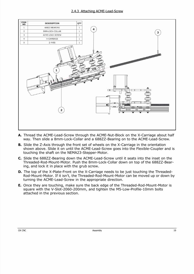
2.4.3 Attaching ACME-Lead-Screw
A. Thread the ACME-Lead-Screw through the ACME-Nut-Block on the X-Carriage about halfway. Then slide a 8mm-Lock-Collar and a 688ZZ-Bearing on to the ACME-Lead-Screw.
B. Slide the Z-Axis through the front set of wheels on the X-Carriage in the orientationshown above. Slide it on until the ACME-Lead-Screw goes into the Flexible-Coupler and istouching the shaft on the NEMA23-Stepper-Motor.
C. Slide the 688ZZ-Bearing down the ACME-Lead-Screw until it seats into the inset on theThreaded-Rod-Mount-Motor. Push the 8mm-Lock-Collar down on top of the 688ZZ-Bear-
ing, and lock it in place with the grub screw.D. The top of the X-Plate-Front on the X-Carriage needs to be just touching the Threaded-
Rod-Mount-Motor. If it isn’t, the Threaded-Rod-Mount-Motor can be moved up or down byturning the ACME-Lead-Screw in the appropriate direction.
E. Once they are touching, make sure the back edge of the Threaded-Rod-Mount-Motor issquare with the V-Slot-2060-200mm, and tighten the M5-Low-Profile-10mm boltsattached in the previous section.
8/17/2019 OX Assembly Manual
http://slidepdf.com/reader/full/ox-assembly-manual 20/44OX CNC Assembly 20
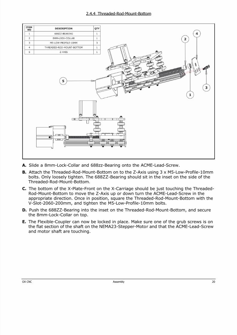
2.4.4 Threaded-Rod-Mount-Bottom
A. Slide a 8mm-Lock-Collar and 688zz-Bearing onto the ACME-Lead-Screw.
B. Attach the Threaded-Rod-Mount-Bottom on to the Z-Axis using 3 x M5-Low-Profile-10mmbolts. Only loosely tighten. The 688ZZ-Bearing should sit in the inset on the side of theThreaded-Rod-Mount-Bottom.
C. The bottom of the X-Plate-Front on the X-Carriage should be just touching the Threaded-Rod-Mount-Bottom to move the Z-Axis up or down turn the ACME-Lead-Screw in theappropriate direction. Once in position, square the Threaded-Rod-Mount-Bottom with the
V-Slot-2060-200mm, and tighten the M5-Low-Profile-10mm bolts.D. Push the 688ZZ-Bearing into the inset on the Threaded-Rod-Mount-Bottom, and secure
the 8mm-Lock-Collar on top.
E. The Flexible-Coupler can now be locked in place. Make sure one of the grub screws is onthe flat section of the shaft on the NEMA23-Stepper-Motor and that the ACME-Lead-Screwand motor shaft are touching.
8/17/2019 OX Assembly Manual
http://slidepdf.com/reader/full/ox-assembly-manual 21/44OX CNC Assembly 21
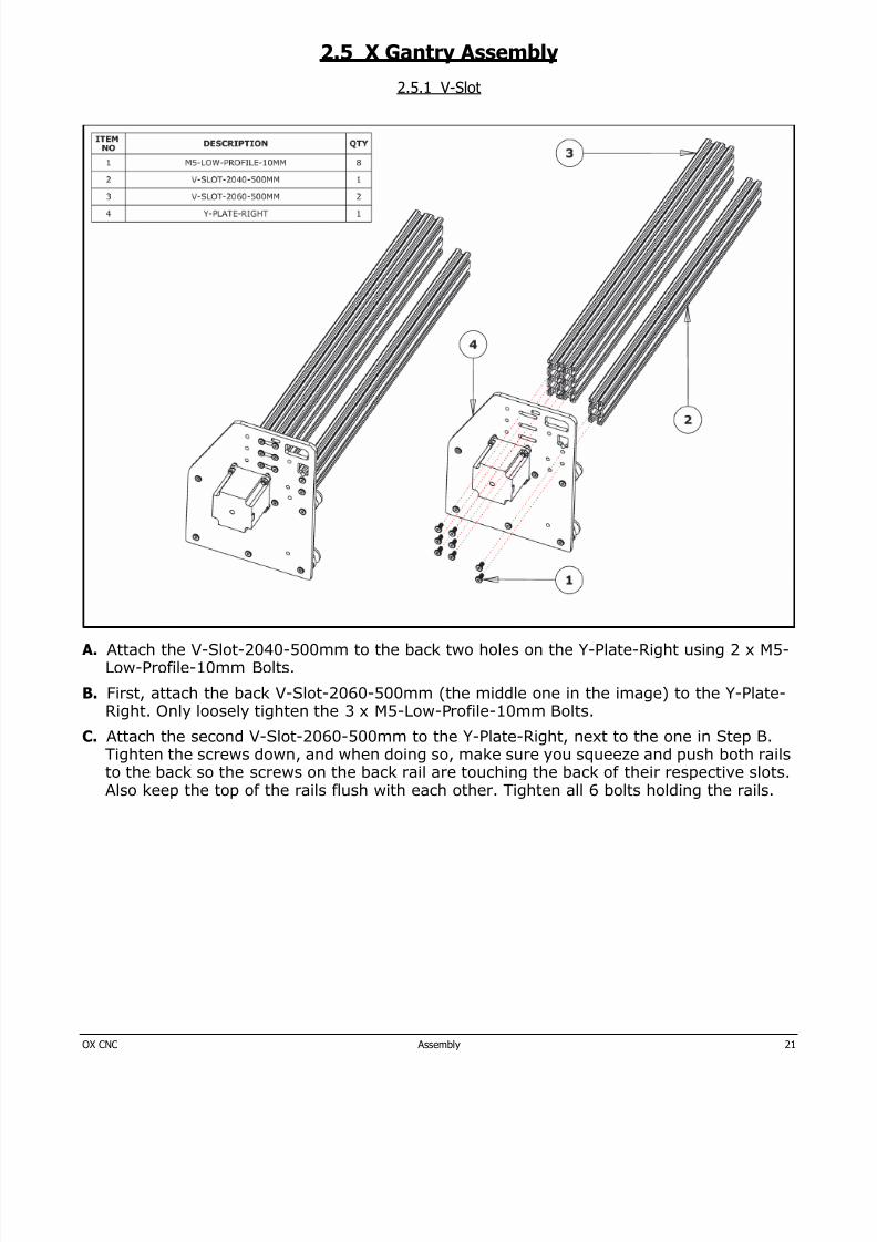
2.5 X Gantry Assembly
2.5.1 V-Slot
A. Attach the V-Slot-2040-500mm to the back two holes on the Y-Plate-Right using 2 x M5-Low-Profile-10mm Bolts.
B. First, attach the back V-Slot-2060-500mm (the middle one in the image) to the Y-Plate-Right. Only loosely tighten the 3 x M5-Low-Profile-10mm Bolts.
C. Attach the second V-Slot-2060-500mm to the Y-Plate-Right, next to the one in Step B.
Tighten the screws down, and when doing so, make sure you squeeze and push both railsto the back so the screws on the back rail are touching the back of their respective slots.Also keep the top of the rails flush with each other. Tighten all 6 bolts holding the rails.
8/17/2019 OX Assembly Manual
http://slidepdf.com/reader/full/ox-assembly-manual 22/44OX CNC Assembly 22
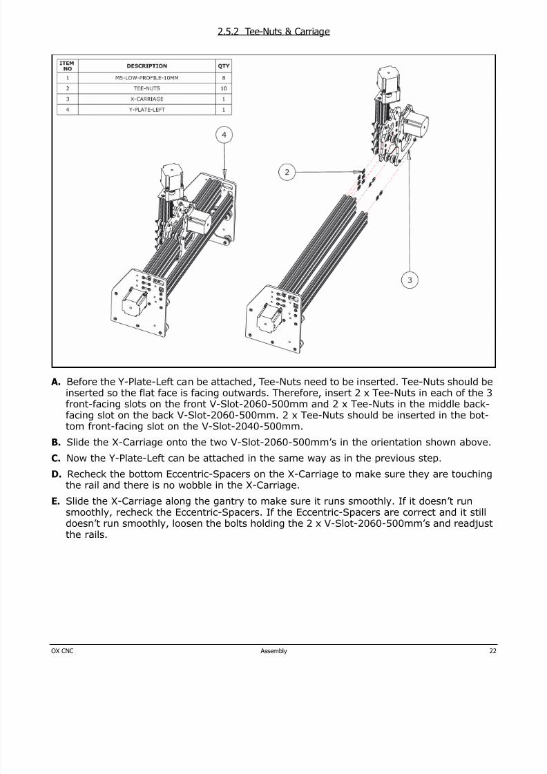
2.5.2 Tee-Nuts & Carriage
A. Before the Y-Plate-Left can be attached, Tee-Nuts need to be inserted. Tee-Nuts should beinserted so the flat face is facing outwards. Therefore, insert 2 x Tee-Nuts in each of the 3front-facing slots on the front V-Slot-2060-500mm and 2 x Tee-Nuts in the middle back-facing slot on the back V-Slot-2060-500mm. 2 x Tee-Nuts should be inserted in the bot-tom front-facing slot on the V-Slot-2040-500mm.
B. Slide the X-Carriage onto the two V-Slot-2060-500mm’s in the orientation shown above.
C. Now the Y-Plate-Left can be attached in the same way as in the previous step.
D. Recheck the bottom Eccentric-Spacers on the X-Carriage to make sure they are touchingthe rail and there is no wobble in the X-Carriage.
E. Slide the X-Carriage along the gantry to make sure it runs smoothly. If it doesn’t runsmoothly, recheck the Eccentric-Spacers. If the Eccentric-Spacers are correct and it stilldoesn’t run smoothly, loosen the bolts holding the 2 x V-Slot-2060-500mm’s and readjustthe rails.
8/17/2019 OX Assembly Manual
http://slidepdf.com/reader/full/ox-assembly-manual 23/44OX CNC Assembly 23
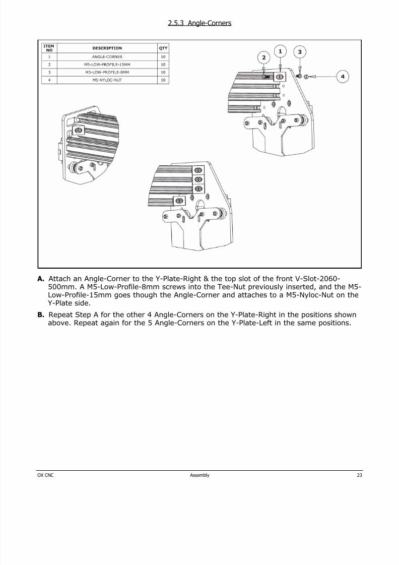
2.5.3 Angle-Corners
A. Attach an Angle-Corner to the Y-Plate-Right & the top slot of the front V-Slot-2060-500mm. A M5-Low-Profile-8mm screws into the Tee-Nut previously inserted, and the M5-Low-Profile-15mm goes though the Angle-Corner and attaches to a M5-Nyloc-Nut on theY-Plate side.
B. Repeat Step A for the other 4 Angle-Corners on the Y-Plate-Right in the positions shownabove. Repeat again for the 5 Angle-Corners on the Y-Plate-Left in the same positions.
8/17/2019 OX Assembly Manual
http://slidepdf.com/reader/full/ox-assembly-manual 24/44OX CNC Assembly 24
2.6 Base Assembly
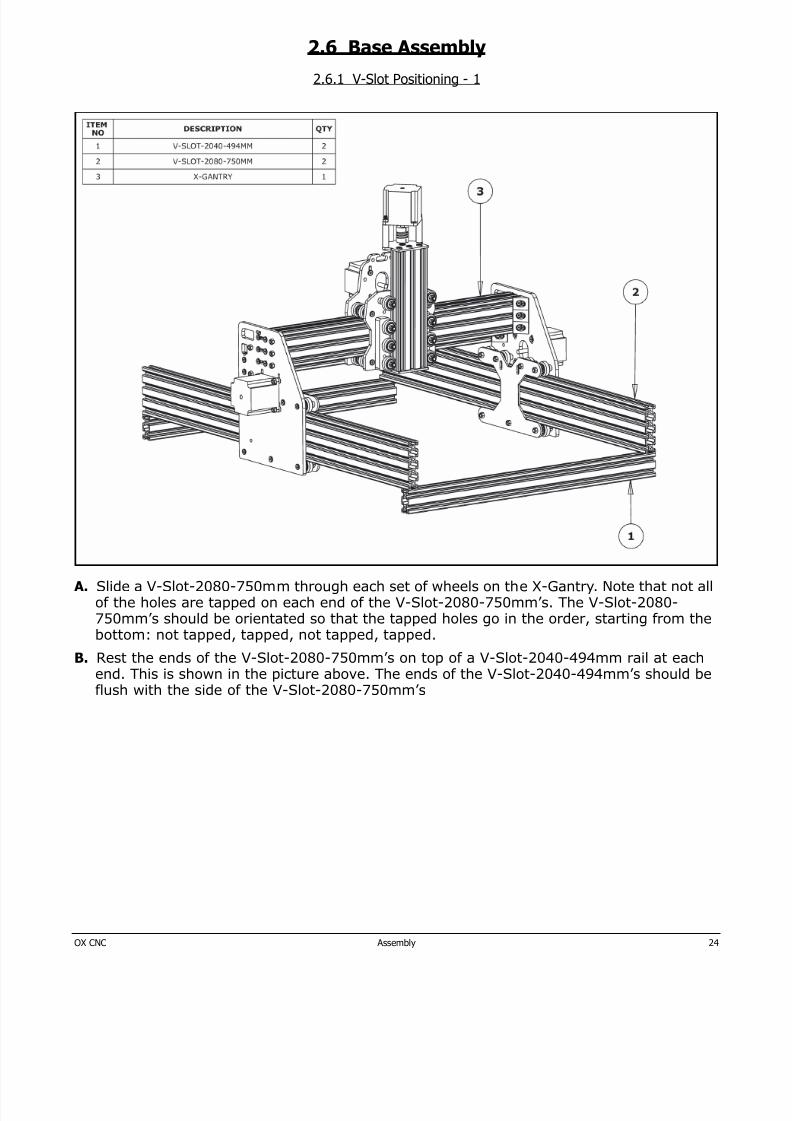
2.6.1 V-Slot Positioning - 1
A. Slide a V-Slot-2080-750mm through each set of wheels on the X-Gantry. Note that not allof the holes are tapped on each end of the V-Slot-2080-750mm’s. The V-Slot-2080-750mm’s should be orientated so that the tapped holes go in the order, starting from thebottom: not tapped, tapped, not tapped, tapped.
B. Rest the ends of the V-Slot-2080-750mm’s on top of a V-Slot-2040-494mm rail at eachend. This is shown in the picture above. The ends of the V-Slot-2040-494mm’s should beflush with the side of the V-Slot-2080-750mm’s
8/17/2019 OX Assembly Manual
http://slidepdf.com/reader/full/ox-assembly-manual 25/44OX CNC Assembly 25
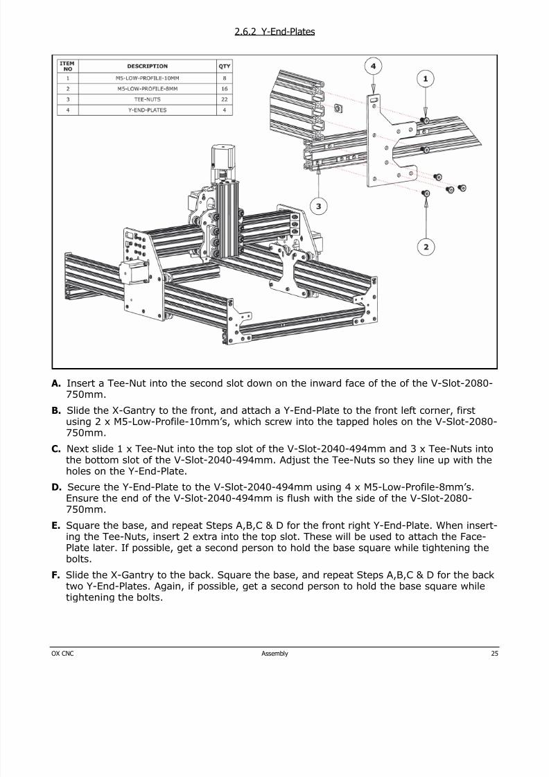
2.6.2 Y-End-Plates
A. Insert a Tee-Nut into the second slot down on the inward face of the of the V-Slot-2080-750mm.
B. Slide the X-Gantry to the front, and attach a Y-End-Plate to the front left corner, firstusing 2 x M5-Low-Profile-10mm’s, which screw into the tapped holes on the V-Slot-2080-750mm.
C. Next slide 1 x Tee-Nut into the top slot of the V-Slot-2040-494mm and 3 x Tee-Nuts intothe bottom slot of the V-Slot-2040-494mm. Adjust the Tee-Nuts so they line up with the
holes on the Y-End-Plate.D. Secure the Y-End-Plate to the V-Slot-2040-494mm using 4 x M5-Low-Profile-8mm’s.
Ensure the end of the V-Slot-2040-494mm is flush with the side of the V-Slot-2080-750mm.
E. Square the base, and repeat Steps A,B,C & D for the front right Y-End-Plate. When insert-ing the Tee-Nuts, insert 2 extra into the top slot. These will be used to attach the Face-Plate later. If possible, get a second person to hold the base square while tightening thebolts.
F. Slide the X-Gantry to the back. Square the base, and repeat Steps A,B,C & D for the backtwo Y-End-Plates. Again, if possible, get a second person to hold the base square whiletightening the bolts.
8/17/2019 OX Assembly Manual
http://slidepdf.com/reader/full/ox-assembly-manual 26/44OX CNC Assembly 26
2.6.3 V-Slot Positioning - 2
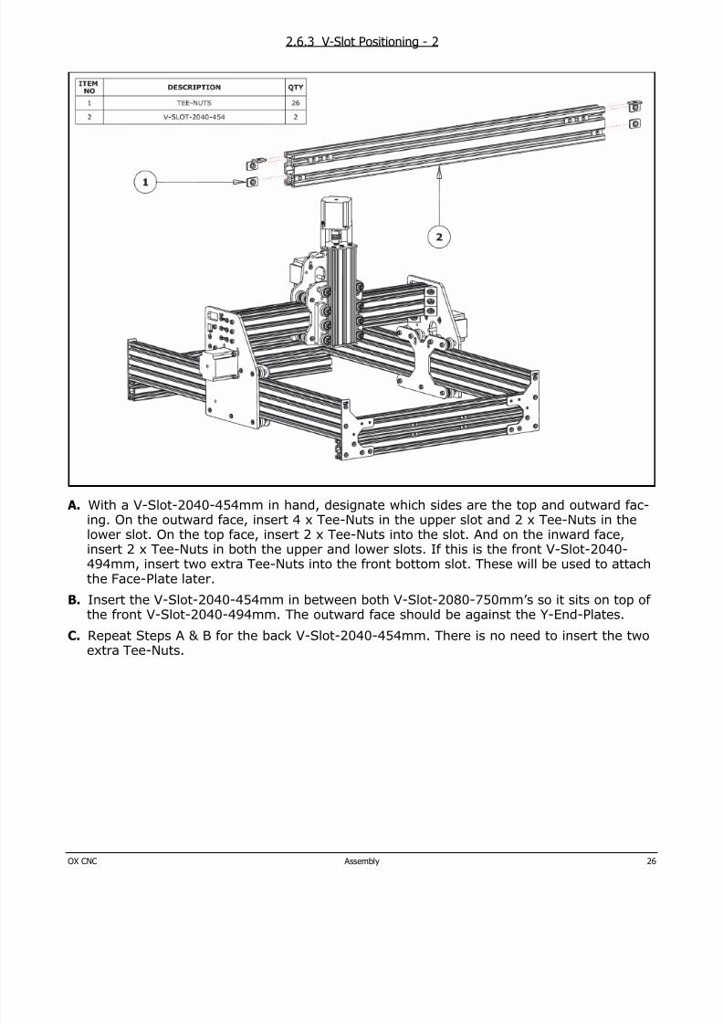
A. With a V-Slot-2040-454mm in hand, designate which sides are the top and outward fac-ing. On the outward face, insert 4 x Tee-Nuts in the upper slot and 2 x Tee-Nuts in thelower slot. On the top face, insert 2 x Tee-Nuts into the slot. And on the inward face,insert 2 x Tee-Nuts in both the upper and lower slots. If this is the front V-Slot-2040-494mm, insert two extra Tee-Nuts into the front bottom slot. These will be used to attachthe Face-Plate later.
B. Insert the V-Slot-2040-454mm in between both V-Slot-2080-750mm’s so it sits on top ofthe front V-Slot-2040-494mm. The outward face should be against the Y-End-Plates.
C. Repeat Steps A & B for the back V-Slot-2040-454mm. There is no need to insert the twoextra Tee-Nuts.
8/17/2019 OX Assembly Manual
http://slidepdf.com/reader/full/ox-assembly-manual 27/44OX CNC Assembly 27
2.6.4 Y-End-Plates - Final Bolts
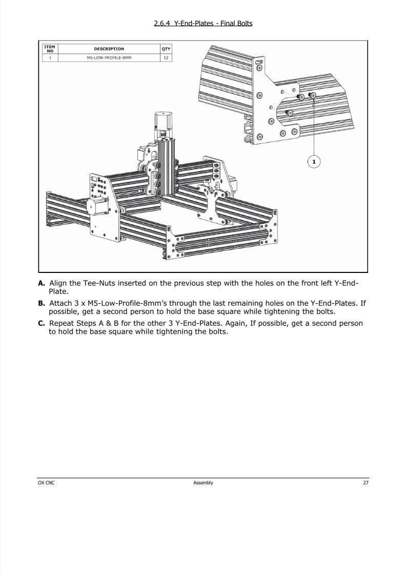
A. Align the Tee-Nuts inserted on the previous step with the holes on the front left Y-End-Plate.
B. Attach 3 x M5-Low-Profile-8mm’s through the last remaining holes on the Y-End-Plates. Ifpossible, get a second person to hold the base square while tightening the bolts.
C. Repeat Steps A & B for the other 3 Y-End-Plates. Again, If possible, get a second personto hold the base square while tightening the bolts.
8/17/2019 OX Assembly Manual
http://slidepdf.com/reader/full/ox-assembly-manual 28/44OX CNC Assembly 28
2.6.5 Angle-Corners
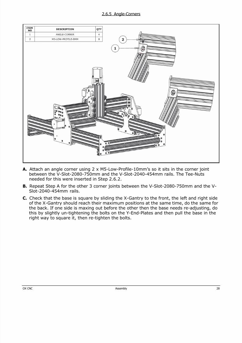
A. Attach an angle corner using 2 x M5-Low-Profile-10mm’s so it sits in the corner jointbetween the V-Slot-2080-750mm and the V-Slot-2040-454mm rails. The Tee-Nutsneeded for this were inserted in Step 2.6.2.
B. Repeat Step A for the other 3 corner joints between the V-Slot-2080-750mm and the V-Slot-2040-454mm rails.
C. Check that the base is square by sliding the X-Gantry to the front, the left and right sideof the X-Gantry should reach their maximum positions at the same time, do the same for
the back. If one side is maxing out before the other then the base needs re-adjusting, dothis by slightly un-tightening the bolts on the Y-End-Plates and then pull the base in theright way to square it, then re-tighten the bolts.
8/17/2019 OX Assembly Manual
http://slidepdf.com/reader/full/ox-assembly-manual 29/44OX CNC Assembly 29
2.6.6 Spoiler Board Support - 1
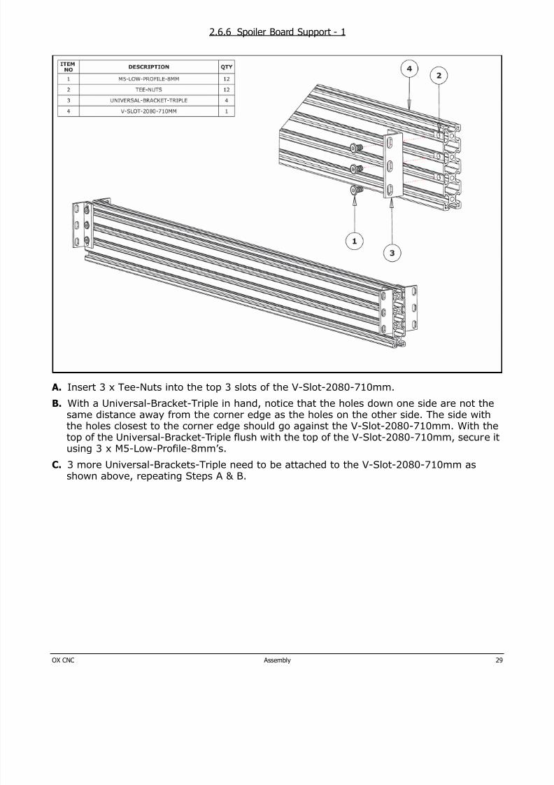
A. Insert 3 x Tee-Nuts into the top 3 slots of the V-Slot-2080-710mm.
B. With a Universal-Bracket-Triple in hand, notice that the holes down one side are not thesame distance away from the corner edge as the holes on the other side. The side withthe holes closest to the corner edge should go against the V-Slot-2080-710mm. With thetop of the Universal-Bracket-Triple flush with the top of the V-Slot-2080-710mm, secure itusing 3 x M5-Low-Profile-8mm’s.
C. 3 more Universal-Brackets-Triple need to be attached to the V-Slot-2080-710mm as
shown above, repeating Steps A & B.
8/17/2019 OX Assembly Manual
http://slidepdf.com/reader/full/ox-assembly-manual 30/44OX CNC Assembly 30
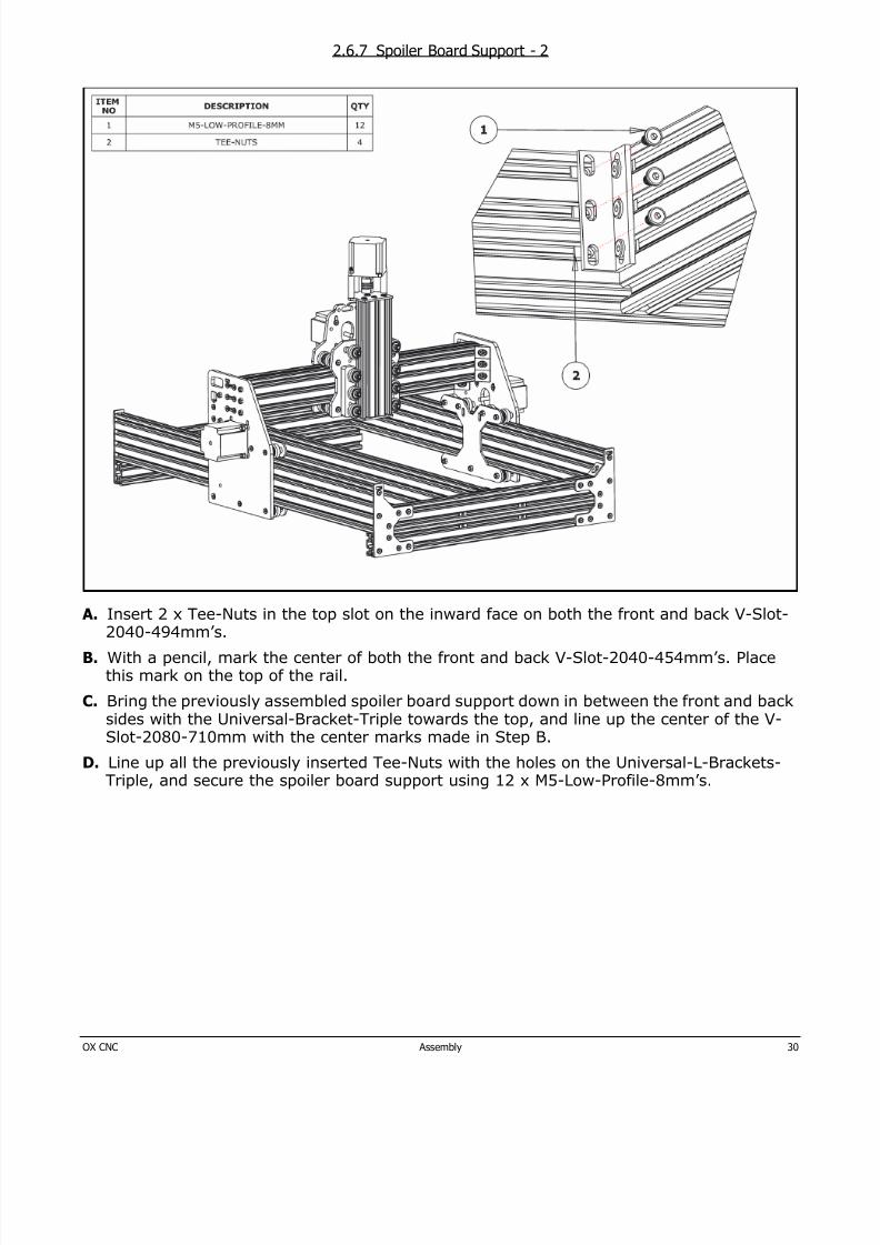
2.6.7 Spoiler Board Support - 2
A. Insert 2 x Tee-Nuts in the top slot on the inward face on both the front and back V-Slot-2040-494mm’s.
B. With a pencil, mark the center of both the front and back V-Slot-2040-454mm’s. Placethis mark on the top of the rail.
C. Bring the previously assembled spoiler board support down in between the front and backsides with the Universal-Bracket-Triple towards the top, and line up the center of the V-Slot-2080-710mm with the center marks made in Step B.
D. Line up all the previously inserted Tee-Nuts with the holes on the Universal-L-Brackets-Triple, and secure the spoiler board support using 12 x M5-Low-Profile-8mm’s.
8/17/2019 OX Assembly Manual
http://slidepdf.com/reader/full/ox-assembly-manual 31/44OX CNC Assembly 31
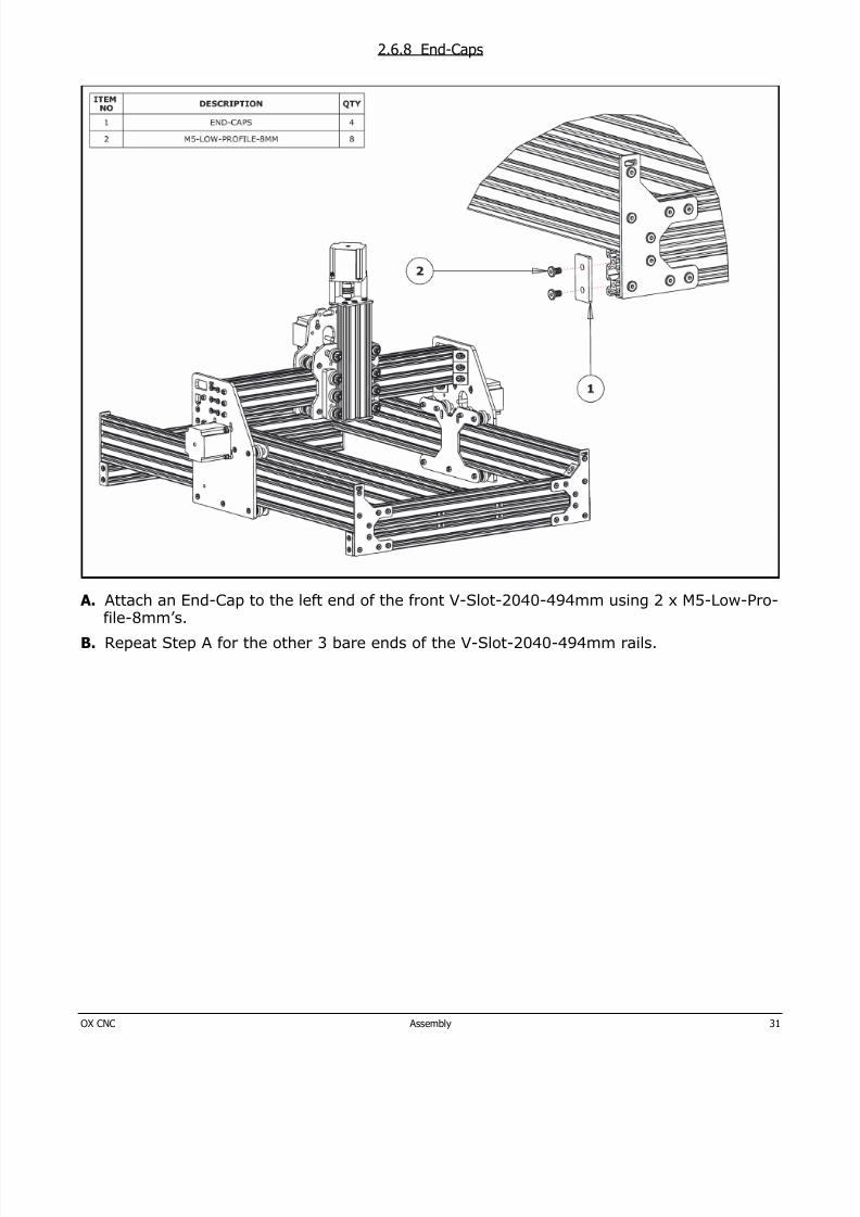
2.6.8 End-Caps
A. Attach an End-Cap to the left end of the front V-Slot-2040-494mm using 2 x M5-Low-Pro-file-8mm’s.
B. Repeat Step A for the other 3 bare ends of the V-Slot-2040-494mm rails.
8/17/2019 OX Assembly Manual
http://slidepdf.com/reader/full/ox-assembly-manual 32/44OX CNC Assembly 32
2.7 GT3-Pulley & Belt Assembly
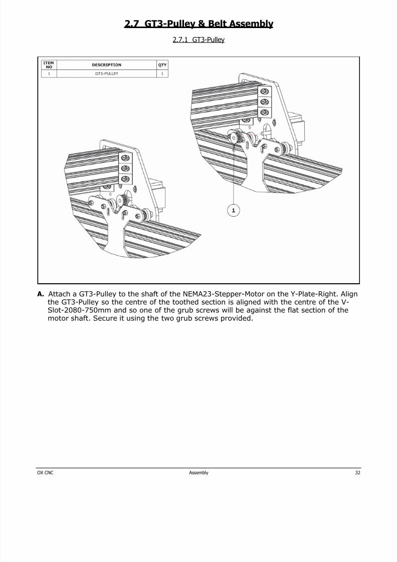
2.7.1 GT3-Pulley
A. Attach a GT3-Pulley to the shaft of the NEMA23-Stepper-Motor on the Y-Plate-Right. Alignthe GT3-Pulley so the centre of the toothed section is aligned with the centre of the V-Slot-2080-750mm and so one of the grub screws will be against the flat section of themotor shaft. Secure it using the two grub screws provided.
8/17/2019 OX Assembly Manual
http://slidepdf.com/reader/full/ox-assembly-manual 33/44OX CNC Assembly 33
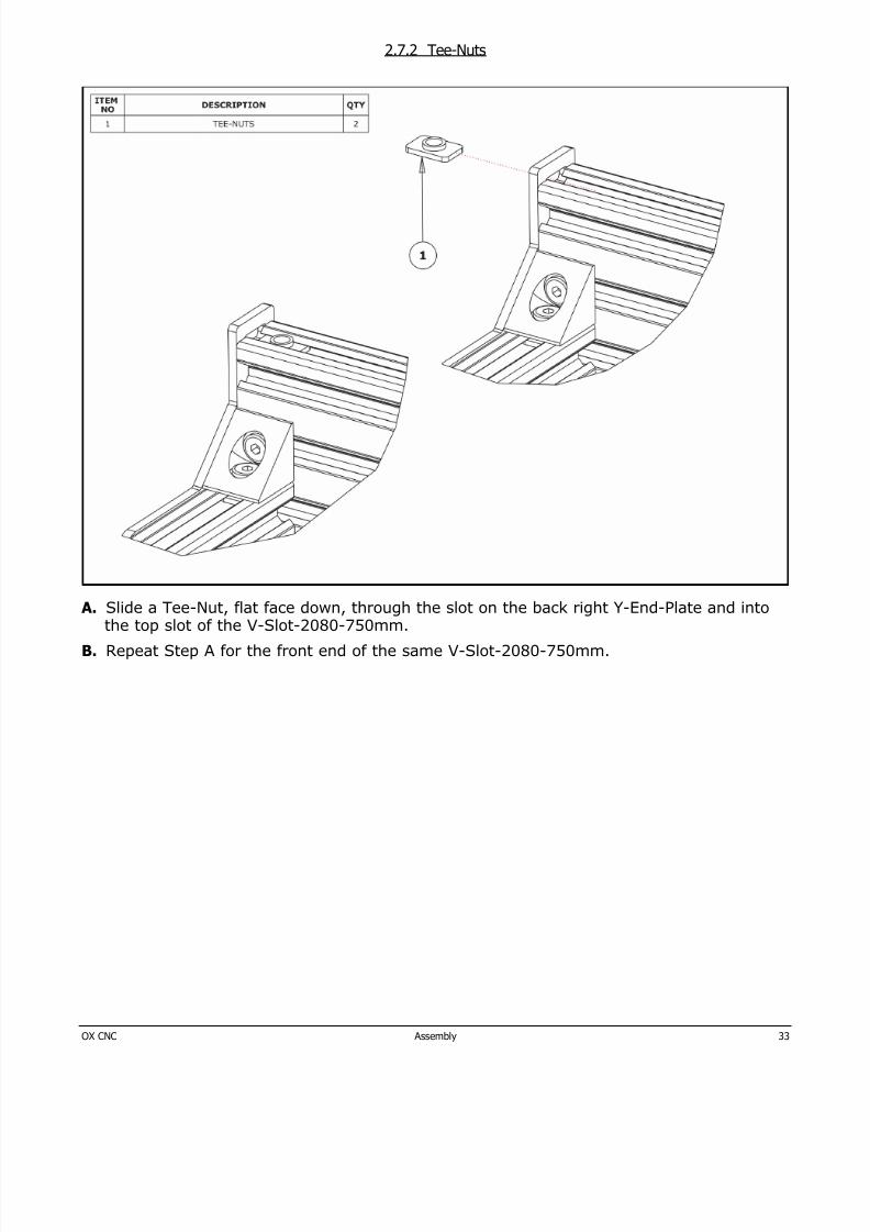
2.7.2 Tee-Nuts
A. Slide a Tee-Nut, flat face down, through the slot on the back right Y-End-Plate and intothe top slot of the V-Slot-2080-750mm.
B. Repeat Step A for the front end of the same V-Slot-2080-750mm.
8/17/2019 OX Assembly Manual
http://slidepdf.com/reader/full/ox-assembly-manual 34/44OX CNC Assembly 34
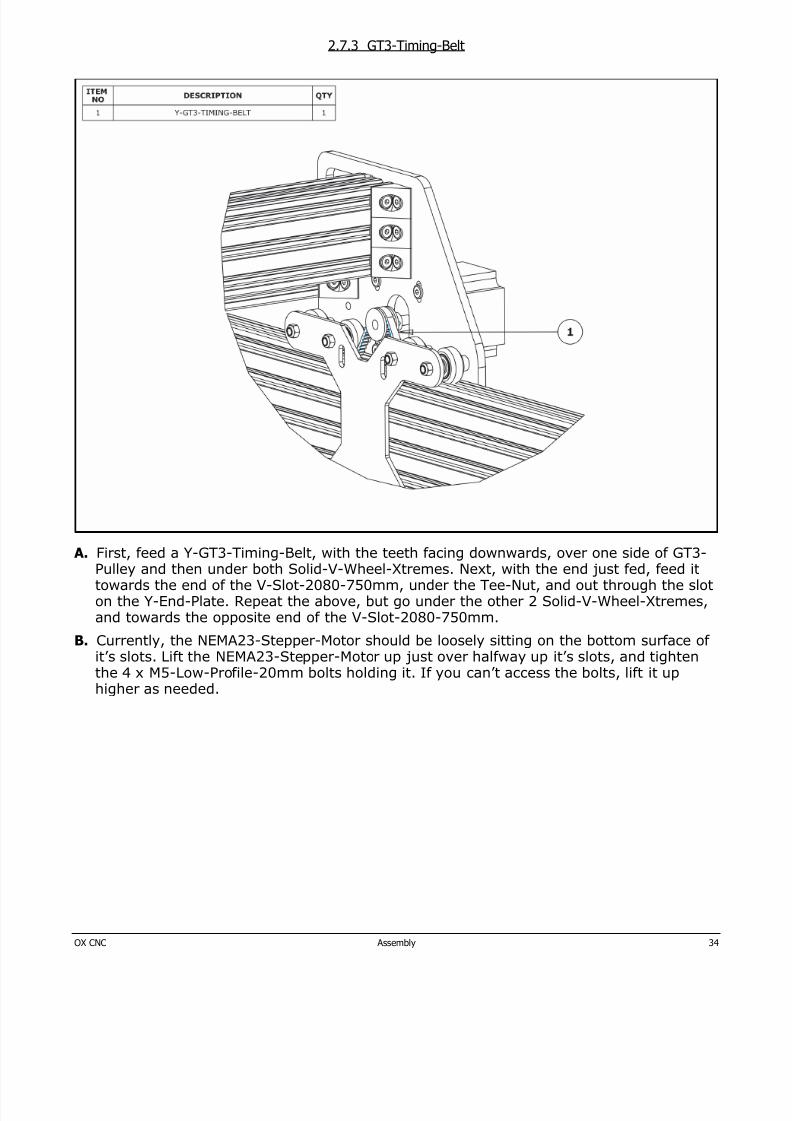
2.7.3 GT3-Timing-Belt
A. First, feed a Y-GT3-Timing-Belt, with the teeth facing downwards, over one side of GT3-Pulley and then under both Solid-V-Wheel-Xtremes. Next, with the end just fed, feed ittowards the end of the V-Slot-2080-750mm, under the Tee-Nut, and out through the sloton the Y-End-Plate. Repeat the above, but go under the other 2 Solid-V-Wheel-Xtremes,and towards the opposite end of the V-Slot-2080-750mm.
B. Currently, the NEMA23-Stepper-Motor should be loosely sitting on the bottom surface ofit’s slots. Lift the NEMA23-Stepper-Motor up just over halfway up it’s slots, and tightenthe 4 x M5-Low-Profile-20mm bolts holding it. If you can’t access the bolts, lift it up
higher as needed.
8/17/2019 OX Assembly Manual
http://slidepdf.com/reader/full/ox-assembly-manual 35/44OX CNC Assembly 35
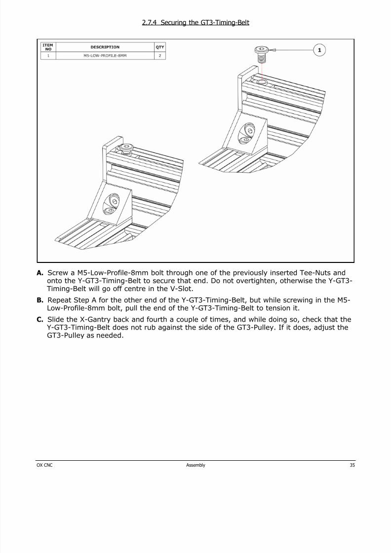
2.7.4 Securing the GT3-Timing-Belt
A. Screw a M5-Low-Profile-8mm bolt through one of the previously inserted Tee-Nuts andonto the Y-GT3-Timing-Belt to secure that end. Do not overtighten, otherwise the Y-GT3-Timing-Belt will go off centre in the V-Slot.
B. Repeat Step A for the other end of the Y-GT3-Timing-Belt, but while screwing in the M5-Low-Profile-8mm bolt, pull the end of the Y-GT3-Timing-Belt to tension it.
C. Slide the X-Gantry back and fourth a couple of times, and while doing so, check that theY-GT3-Timing-Belt does not rub against the side of the GT3-Pulley. If it does, adjust the
GT3-Pulley as needed.
8/17/2019 OX Assembly Manual
http://slidepdf.com/reader/full/ox-assembly-manual 36/44OX CNC Assembly 36
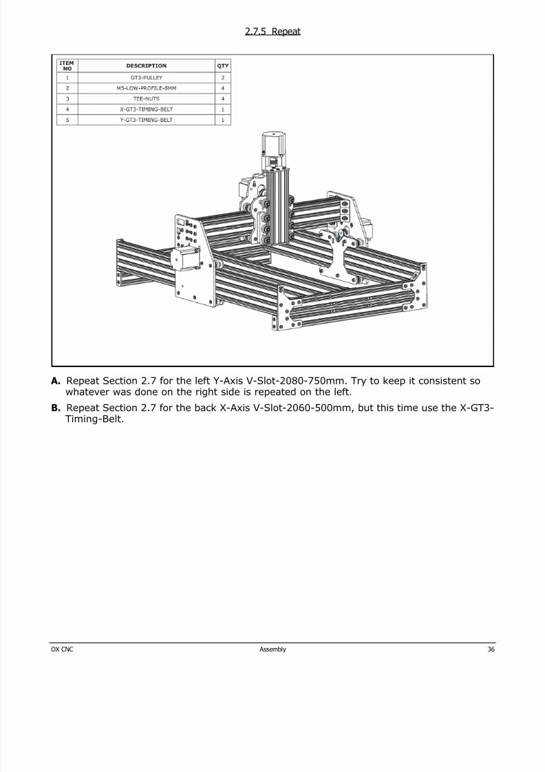
2.7.5 Repeat
A. Repeat Section 2.7 for the left Y-Axis V-Slot-2080-750mm. Try to keep it consistent sowhatever was done on the right side is repeated on the left.
B. Repeat Section 2.7 for the back X-Axis V-Slot-2060-500mm, but this time use the X-GT3-Timing-Belt.
8/17/2019 OX Assembly Manual
http://slidepdf.com/reader/full/ox-assembly-manual 37/44OX CNC Assembly 37
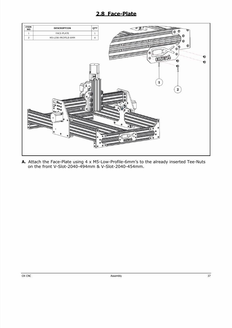
2.8 Face-Plate
A. Attach the Face-Plate using 4 x M5-Low-Profile-6mm’s to the already inserted Tee-Nutson the front V-Slot-2040-494mm & V-Slot-2040-454mm.
8/17/2019 OX Assembly Manual
http://slidepdf.com/reader/full/ox-assembly-manual 38/44OX CNC Assembly 38
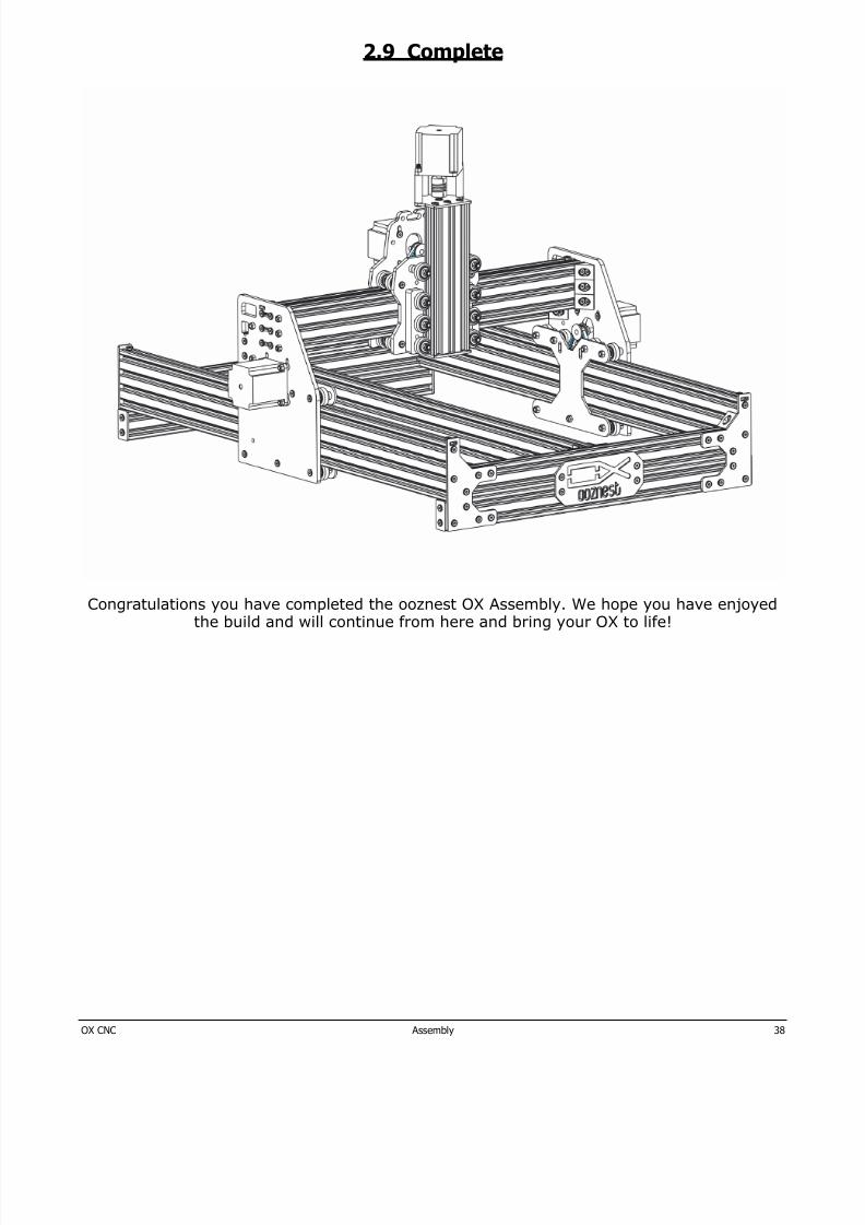
2.9 Complete
Congratulations you have completed the ooznest OX Assembly. We hope you have enjoyedthe build and will continue from here and bring your OX to life!

8/17/2019 OX Assembly Manual
http://slidepdf.com/reader/full/ox-assembly-manual 39/44OX CNC Appendix 39
3.0 Appendix
8/17/2019 OX Assembly Manual
http://slidepdf.com/reader/full/ox-assembly-manual 40/44OX CNC Appendix 40
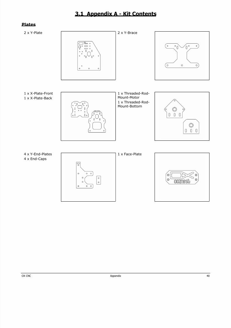
3.1 Appendix A - Kit Contents
Plates
2 x Y-Plate 2 x Y-Brace
1 x X-Plate-Front
1 x X-Plate-Back
1 x Threaded-Rod-Mount-Motor
1 x Threaded-Rod-Mount-Bottom
4 x Y-End-Plates
4 x End-Caps
1 x Face-Plate
8/17/2019 OX Assembly Manual
http://slidepdf.com/reader/full/ox-assembly-manual 41/44OX CNC Appendix 41
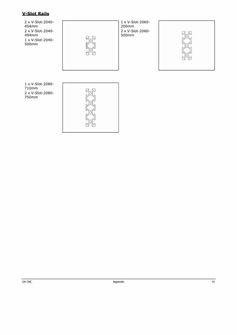
V-Slot Rails
2 x V-Slot-2040-454mm
2 x V-Slot-2040-494mm
1 x V-Slot-2040-500mm
1 x V-Slot-2060-200mm
2 x V-Slot-2060-500mm
1 x V-Slot-2080-710mm
2 x V-Slot-2080-750mm
8/17/2019 OX Assembly Manual
http://slidepdf.com/reader/full/ox-assembly-manual 42/44OX CNC Appendix 42
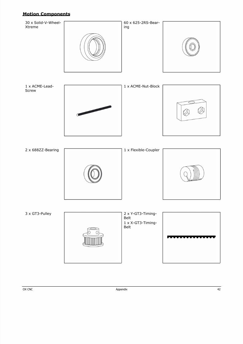
Motion Components
30 x Solid-V-Wheel-Xtreme
60 x 625-2RS-Bear-ing
1 x ACME-Lead-Screw
1 x ACME-Nut-Block
2 x 688ZZ-Bearing 1 x Flexible-Coupler
3 x GT3-Pulley 2 x Y-GT3-Timing-Belt
1 x X-GT3-Timing-Belt
8/17/2019 OX Assembly Manual
http://slidepdf.com/reader/full/ox-assembly-manual 43/44OX CNC Appendix 43
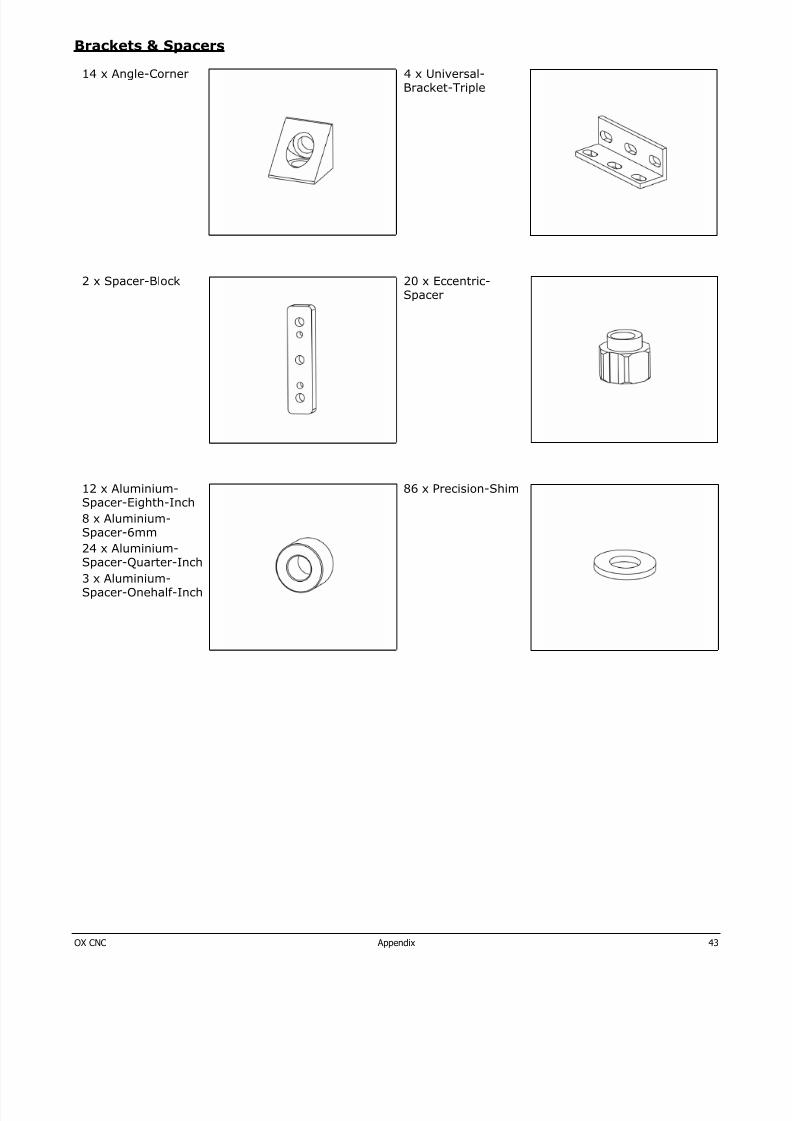
Brackets & Spacers
14 x Angle-Corner 4 x Universal-Bracket-Triple
2 x Spacer-Block 20 x Eccentric-Spacer
12 x Aluminium-Spacer-Eighth-Inch
8 x Aluminium-Spacer-6mm
24 x Aluminium-Spacer-Quarter-Inch
3 x Aluminium-Spacer-Onehalf-Inch
86 x Precision-Shim
8/17/2019 OX Assembly Manual
http://slidepdf.com/reader/full/ox-assembly-manual 44/44
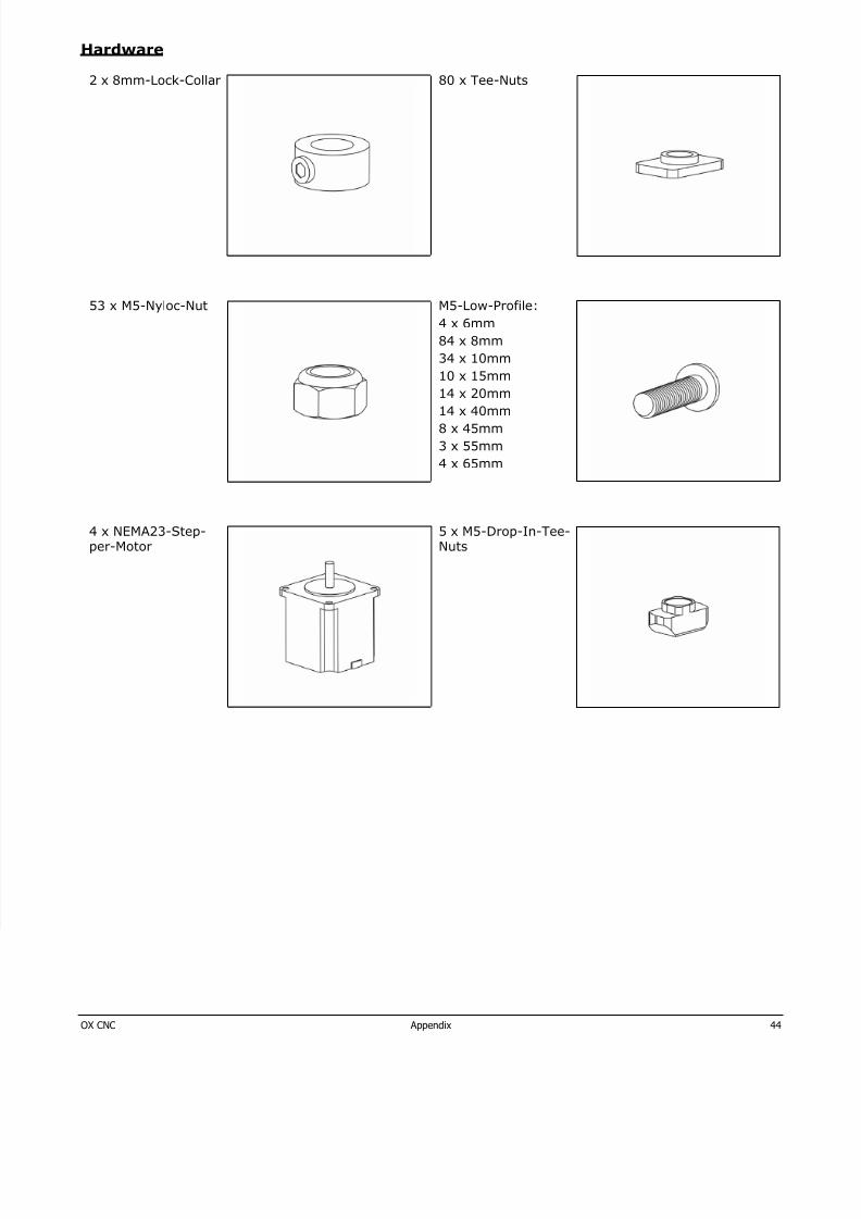
Hardware
2 x 8mm-Lock-Collar 80 x Tee-Nuts
53 x M5-Nyloc-Nut M5-Low-Profile:
4 x 6mm
84 x 8mm
34 x 10mm
10 x 15mm
14 x 20mm
14 x 40mm
8 x 45mm
3 x 55mm
4 x 65mm
4 x NEMA23-Step-per-Motor
5 x M5-Drop-In-Tee-Nuts