Embed Size (px)
Citation preview

A Novel Steady-state Technique for Measuring the Heat Extracted by Secondary Cooling Sprays
C.A. Hernández, A.H. Castillejos, F.A. Acosta, X. Zhou* and B.G. Thomas* Department of Metallurgical Engineering
CINVESTAV – Unidad Saltillo Carr. Saltillo-Monterrey Km. 13, Apdo. Postal 663
Saltillo, 25000, Coahuila, México Tel.: +52-844-438-9600 Fax: +52-844-438-9610
E-mail: [email protected] *Department of Mechanical Science and Engineering
University of Illinois at Urbana-Champaign 1206 West Green Street, Urbana, IL 61801
Tel.: 217-333-6919 Fax: 217-244-6534
E-mail: [email protected]
Key words: Boiling heat flux, Measuring apparatus, Steady-state test, Secondary cooling, Continuous casting
ABSTRACT This paper presents a new technique for measuring the steady-state heat flux extracted locally by water sprays or air-mists impinging upon the surface of a hot metallic body. The technique is based on balancing the induction heating of a metallic sample with the heat removed by the boiling of spray droplets impinging on its exposed surface. Measurement of the RMS current flowing through the induction coil for maintaining a desired sample temperature, together with the solution of a two-dimensional axisymmetric computational model of the electromagnetic and heat conduction equations, enable estimation of the heat extracted by the cooling spray. Heat fluxes are reported for spray cooling of a Pt sample at temperatures spanning from 200-1200°C, using air-mist nozzles and operating conditions relevant to continuous casting of thin steel slabs. The results demonstrate the flexibility of the technique for investigating different aspects of spray cooling.
INTRODUCTION
Spray cooling technology for high temperatures surfaces plays a prominent role in many metal production systems, as well as in other systems, e.g., nuclear reactors, fire extinguishers and microelectronic chips. In the continuous casting of steel, direct spray impingement is responsible for removing on average ~60 % of the total thermal energy contained in conventional1,2 and CSP thin slabs.3 Of the different heat extraction modes occurring in the secondary cooling system of CC machines (i.e., direct spray impingement, roll contact and convection to draining water)4, spray cooling is controllable through the selection of nozzle type, nozzle operating conditions and nozzle position with respect to the strand. These features make water sprays and air-mists ideally suited for controlling the heat extraction distribution on the strand surface, and thus for achieving optimum levels of quality and productivity. With this objective in mind, spray cooling technology has been intensively investigated since the 1960´s1,5 and continues to be a very active field for research. The purpose of the research works has been to understand how the nozzle type (hydraulic, pneumatic with internal mixing, pneumatic with external mixing), the discharge pattern (hollow cone, full cone, flat spray) and the operating conditions (air and/or water flow rates and pressures) affect the spray and mist characteristics (droplet size, droplet velocity and droplet concentration) and ultimately their heat extraction capabilities.6-17 The heat transfer performance of water sprays and air-mists has been experimentally investigated by two methods: steady- and unsteady state. In the steady state methods, a specimen is heated and spray cooled at the same time to maintain its temperature constant.9,10,13-16,18-23 Under these conditions, the temperature of the surface, Ts, and the heat transfer coefficient, h, associated to boiling of the water impinging on it are evaluated from Fourier’s law of heat conduction and Newton law of convection. In the case of
81

transient methods the approach is to expose a surface of the hot test-specimen to the spray and simultaneously record, the temperature-time history at specific near surface locations during cooling.6-8,11,13,14,16,17,24-28 Determination of Ts and h requires the numerical calculation of the heat flux for each time interval, through the solution of the inverse heat conduction problem. From the literature, it is clear that transient methods allow the monitoring of the cooling of the surface of the test-specimen along the different regimes of the conventional boiling curve, i.e., film boiling, transition boiling and nucleation boiling. On the other hand, the reported steady state experimental tests have been restricted only to temperatures in the lower part of the nucleation boiling regime and in the film boiling regime, i.e., to regions where the boiling heat flux varies little with temperature. Therefore, only few comparisons between the two procedures have been done. In the nucleate boiling region, Ishigai et al.18 found discrepancies between the two methods and these were attributed to inaccuracies in the transient one, while in the film boiling region both techniques matched reasonably well. Olden et al.14 found that the two methods compared well in the temperature range from 200-500°C, but not outside it; however the comparison did not involve totally similar spraying conditions. Investigators have reported pros and cons of both methods. Thus, it has been claimed9 that the steady method is more convenient for determining the dependence of h on nozzle operating conditions, in the film boiling region, and that the transient technique is better suited for studying the dependence of h with Ts, particularly in the transition boiling regime. Also, it has been argued that the steady state method is faster than the unsteady one9,10 and that also has the advantage of being independent of the response time of the thermocouples and the data acquisition system.9 The application of the steady state method has been found to be limited by the maximum attainable power densities, which limits the size of the test-specimen, the water impact flux w, that can impinge upon it, the maximum specimen temperature and the time that the steady state can be maintained. The measuring apparatus of Olden et al.14 was used to carry out steady and unsteady state tests. When operating in steady mode, the specimen temperatures were restricted to temperatures between 70-500°C and to a maximum water impact flux to 2 L/m2s, but in transient mode the apparatus did not present these disadvantages. Schmidt et al.19 indicated that in their apparatus the quasi-steady state could only be maintained for a period of 10-60 s. The literature cites the use of different types of heating media for the stationary and transient test apparatuses developed for evaluating the boiling heat transfer coefficients with sprays. In the case of the stationary test rigs, the heating medium is very critical since it must provide a sufficient power to balance the heat extracted by the spray through the active surface of the body, which may be required to be at 1200°C, and also, it must not interfere with the spray and neither cause hazardous conditions. Heating methods have involved direct resistance heating,10,13,16,18,19 electrical rod or wire elements21-23 and gas burners.9,14,15,20 Electrical resistance heating involves passing current through a thin test-plate to heat it by the Ohmic resistance of the plate material itself. In the case of the electrical rods, this same affect heats up these elements which are mounted watertight in intimate contact with the test-plate. The methods based on direct resistance heating have been applied for 2.5≤w (L/m2s)≤33.3 and over a narrow range of surface temperatures belonging to the film boiling region, 900-1000°C.10,13 These measurements which include conditions relevant to continuous casting have indicated that, if a running water film is superimposed to an impinging spray, the heat transfer coefficient increases strongly for low w values, but only slightly for high w values.10 Toda23 used electrical heating elements for studying the mist cooling of a metallic surface, at up to 300°C, while subjected to 3.4≤w (L/m2s)≤14.3. Other works employing electrical rod elements have been concerned with the mist cooling of surfaces at temperatures below the normal boiling point of the cooling liquid21 or to the cooling of surfaces at temperatures between 200-900°C, which are impinged by streams of drops with a frequency of 0.5-3.0 drops/s.22 Jenkins et al.9 studied air-mist cooling under conditions of interest to continuous casting by employing a steady state technique that used a gas flame as the heating media. From their experimental results, they concluded that a close control of the water flow rate, W, and the air nozzle pressure, pa, is required to get an optimum cooling performance of air-mist nozzles. The use of induction heating in steady state apparatuses, for measuring boiling heat transfer coefficients with sprays, has not found application. It has been claimed that the coil wrapped around the test-specimen would interfere with the flow of water from the spray.20 However, certain transient test rigs have taken advantage of induction heating for avoiding moving the test-specimen from the heating station to the spraying station.7,25 The motion of the specimen has been blamed for causing the damage the thermocouples in transient techniques.20
The surface temperatures of the strand passing through the secondary cooling system of continuous steel casters vary from ~1200-750°C over the total length of the system and the water impingement densities from 5-80 L/m2s, over the greater proportion of the spray footprints. Therefore, heat transfer may occur in the regimes of stable film boiling and transition boiling or completely into the last one, as unsteady steady measurements have indicated for the case of modern nozzles that produce fine high velocity droplets.12,28 The transient measuring technique has allowed to obtain boiling heat flux correlations which have been very useful for the development of mathematical models that have led to improvements in secondary cooling strategies.29-30 However, in this technique the cooling of the test specimen occurs so fast that it would be difficult, if not impossible, to carry out observations of the boiling phenomena taking place along the entire boiling curve or about the effect that the formation of surface deposits would have on heat extraction. Therefore, as a first step to gain better understanding of spray cooling, this work presents a novel steady state technique based on balancing the heat extracted from the sample surface by the boiling water droplets, with the heat supplied by electromagnetic induction. In this technique, the measurement of the RMS current, Im, flowing through the coil to maintain a desired sample temperature, Tm, together with the solution of a two-dimensional axis-symmetric computational model of the electromagnetic and heat conduction equations enable estimation of the heat extracted by spray cooling. Experiments were carried out by stepwise increasing and decreasing of the specimen temperature from 200°C to 1200°C and then back down to 200°C. Our results indicate that the
82
technique enables the precise and systematic measurement of entire boiling curves under the intense spraying conditions of interest to steel continuous casting.
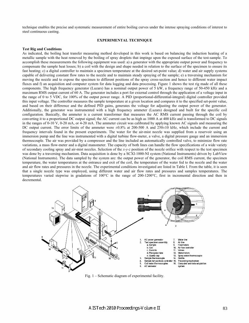
EXPERIMENTAL TECHNIQUE Test Rig and Conditions As indicated, the boiling heat transfer measuring method developed in this work is based on balancing the induction heating of a metallic sample with the heat removed by the boiling of spray droplets that impinge upon the exposed surface of the test-sample. To accomplish these measurements the following equipment was used: a) a generator with the appropriate output power and frequency to compensate the sample heat losses; b) a coil with the design and shape needed in relation to the surface of the specimen to ensure its fast heating; c) a digital controller to maintain a specimen temperature at the desired set-point value; d) water and air supply systems capable of delivering constant flow rates to the nozzle and to maintain steady spraying of the sample; e) a traversing mechanism for moving the nozzle and to expose the specimen to different positions of the spray cross-section and hence to different water impact fluxes and f) an acquisition and computer system for data logging and data processing. Figure 1 shows the test rig made of all these components. The high frequency generator (Luzars) has a nominal output power of 5 kW, a frequency range of 50-450 kHz and a maximum RMS output current of 60 A. The generator includes a port for external control through the application of a voltage input in the range of 0 to 5 VDC, for 100% of the output power range. A PID (proportional-differential-integral) digital controller provided this input voltage. The controller measures the sample temperature at a given location and compares it to the specified set-point value, and based on their difference and the defined PID gains, generates the voltage for adjusting the output power of the generator. Additionally, the generator was instrumented with a high frequency ammeter (Luzars) designed and built for the specific coil configuration. Basically, the ammeter is a current transformer that measures the AC RMS current passing through the coil by converting it to a proportional DC output signal; the AC current can be as high as 1000 A at 400 kHz and is transformed to DC signals in the ranges of 0-10 V, 0-20 mA, or 4-20 mA. The ammeter circuit was calibrated by applying known AC signals and measuring the DC output current. The error limits of the ammeter were ±0.8% at 200-500 A and 250±10 kHz, which include the current and frequency intervals found in the present experiments. The water for the air-mist nozzle was supplied from a reservoir using an immersion pump and the line was instrumented with a digital turbine flow-meter, a valve, a digital pressure gauge and an immersion thermocouple. The air was provided by a compressor and the line included an automatically controlled valve, to minimize flow rate variations, a mass flow-meter and a digital manometer. The capacity of both lines can handle the flow specifications of a wide variety of secondary cooling spray and air-mist nozzles. Selection of the x-y-z position of the nozzle orifice with respect to the test specimen was done by a traversing mechanism. Data acquisition is done by a SCXI-1000-NI system (National Instruments) driven by LabView (National Instruments). The data sampled by the system are: the output power of the generator, the coil RMS current, the specimen temperature, the water temperatures at the entrance and exit of the coil, the temperature of the water fed to the nozzle and the water and air flow rates and pressures in the nozzle. The experimental conditions investigated are listed in Table I. From the table, it is seen that a single nozzle type was employed, using different water and air flow rates and pressures and samples temperatures. The temperatures varied stepwise in gradations of 100°C in the range of 200-1200°C, first in incremental direction and then in decremental.
Fig. 1 – Schematic diagram of experimental facility.
83

Test-Specimen Assembly The specimen assembly shown in Fig. 1 is made of a platinum disk instrumented with an R-type thermocouple and wrapped around by a coil, both encased in insulating ceramic forming a monolith. Care is used to ensure that, in its as-cast state, the ceramic fills very well the gaps between the specimen and the coil and establishes an intimate union with both of them, leaving no crevices in between. As seen in the figure, the monolith is placed inside a Plexiglas tube which front is covered by a quartz cap with a central hole; this arrangement leaves only the frontal face of the Pt-disk exposed to the impingement of the spray water droplets. The disk (8mm, 2.5 mm thickness) has the thermocouple (0.5 mm ∅) welded at the center of its back surface to register what is called the sample temperature Tm. As shown in the figure, the terminals of the coil exit through holes in the Plexiglas tube and the thermocouple is withdrawn through a small orifice on the back cover. For additional protection against humidity the ceramic body, made from a SiO2 castable ceramic, is coated with waterproof paint. As shown in Figure 1 the coil used has two turns and was formed in a mold that flattened the copper-tube of 3.175 mm internal diameter. The forming procedure allowed closing the turns tightly, i.e., to complete as close as possible each of the turns, despite the small diameter and also minimized variations among fabricated coils. The platinum disk exhibited excellent dimensional stability and did not oxidize under the test conditions employed. These characteristics ensured the maintenance of a constant separation between the specimen and the coil, favoring stable induction, and also they ensured the tight sealing of the lateral disk face by the ceramic, inhibiting water penetration. During construction of the test-assembly, a centering device is used to align the center of the disk with the center of the coil, before the ceramic is cast. The quartz cap has a thickness of 0.5 mm, so it does not form a thick step for the accumulation of water, and neither produces a shadow that could interfere with the arrival of droplets to the front of the platinum disk, when this is off-center relative to the nozzle axis. The thermo-physical properties of the components of the test assembly are also listed in Table I.
Table I – Experimental conditions, thermo-physical properties and heat transfer parameters. Experimental conditions
Nozzle W= 0.076 L/s; A= 1.33 NL/s; A/W= 17.5; pw= 475 kPa; pa= 448 kPa Delavan W19822 W= 0.043 L/s; A= 1.61 NL/s; A/W= 37.4; pw= 324 kPa; pa= 310 kPa
Tm from 200°C to 1200°C in steps of 100°C Thermophysical properties of test assembly materials
Material Thermal conductivity k,
W/mK
Emissivity ε Density ρ,kg/m3
Electrical conductivity σ,
mho/m
Relative magnetic permeability*, μR
Platinum 71.3382 + 2.2147×10⁻³T+ 1.0035×10⁻⁵T2 **
0.031555 + 1.3972×10⁻⁴T- 2.1119×10⁻⁸T2 **
21450 [1.75×10⁻⁸ (1+ 0.0039(T-20)]-1 **
1
Copper (at 100°C)
390 --- 8900 4.3×10⁷ *** 1
Ceramic 0.58 **** k(T)see Fig. 4(b)
--- 1762 --- ---
Heat transfer coefficients Natural convection to air hair, W/m2K 10; from correlation35 Nu= 0.54 (GrPr)0.25 Forced convection to cooling hCu, W/m2K 55470; from correlation35 Nu= 0.023 Re0.8Pr0.4
*μR= μ/μo, where μ is the magnetic permeability and μo is the free space magnetic permeability and is equal to 4π x 10-7 H/m. **Obtained from reference 32. ***Obtained from reference 33. **** Obtained from reference 34.
Analysis of the Experimental Data According to the experimental technique once the test-specimen assembly reaches thermal equilibrium, the measured temperature, Tm, at the center of the back surface of the Pt-sample becomes equal to the set-point, specified in the controller, and the measured RMS (i.e., root mean square) current, Im, passing through the coil stabilizes at a particular value, such that the heat input by electrical energy compensates exactly the heat losses through its boundaries. Additionally, considering that each coil turn closely approaches a toroid then it can be assumed that the test-specimen assembly has axial symmetry, as shown in Fig. 2, and then the energy balance over the whole test-specimen assembly can be written in terms of the 2-D heat conduction equation, given as,
01 =+⎟⎠⎞⎜
⎝⎛
∂∂
∂∂+⎟
⎠⎞⎜
⎝⎛
∂∂
∂∂
vqzTk
zrTkr
rr (1)
where r and z are radial and axial coordinate positions, k and T are thermal conductivity and temperature and qv is the source term representing the generation of energy per unit volume. The last term arises from the Joule heating effect associated to the flow of external current through the Cu-coil and to the current induced electromagnetically in the Pt-sample; the induced current heats-up the Pt-specimen but the coil-current also affects the thermal state of the test-assembly. The term qv is expressed as,
84

}JJRe{qv ⋅=σ21 (2)
where σ is the electrical conductivity of the particular conductor and Re stands for the real part of the module of the current density J (=Jφeφ) passing through the particular conductor, i.e., Pt or Cu; since for the specific geometry of the system the current flows only in the angular direction the subscript φ denotes this direction and e is a unit vector. From Figure 2 it can be seen that the problem involves the following boundary conditions: a) symmetry at the axis; b) free convection to the ambient air through the back and lateral surfaces of the domain; c) forced convection from the internal walls of the coil turns to the water flowing inside; d) zero heat flux through the quartz cap, since this is placed slightly ahead of the front surface of the Pt-specimen and no heat losses are assumed; and e) boiling convection plus radiation over the front face of the Pt-disk. Thus, it is realized that the estimation of the heat flux removed by the boiling of the impinging spray droplets involves the solution of an inverse heat conduction problem, to calculate the boiling convection boundary condition that minimizes the error between the computed, Tc, and measured, Tm, sample temperatures.
Fig. 2 – Schematics of the computational domain and boundary conditions; the dimensions are given in mm and the subscripts w, coil, Cu, c and f denote water in spray, water inside coil, copper, ceramic and ambient air, respectively.
The distribution of current density in the coil turns and the specimen, which appears in Eq. (2), can be estimated from the following expression,31
∫ =+S
kkiik
kk VdsMJjLJ,ω
σ (3)
relating the Ohmic voltage and the induced electromotive force, terms on the left, to the external voltage applied to an AC circuit, term on the right. In the equation the subscript k (= 1, 2, ….i, …,n) denotes discrete closed circuits of differential cross section area ds and length Lk, shaping-up the conductors in the system with a total surface area S; ω (=2πf) is the current frequency (s-1); j is the imaginary number 1− ; V is the external voltage applied to a closed circuit of length L and Mi,k, which is a measure of the inductive interaction between closed circuits i and k, is called the mutual inductance and is defined as,
∫=L ki
kikki r
dLdLM,
, 4πμ (4)
where μ is the magnetic permeability and ri,k is the separation distance between the differential length elements dLi and dLk. The discretization of Eq. (3) leads to a set of simultaneous algebraic linear equations that can be solved to compute the distribution of current density in the coil and in the Pt sample, if the external voltage is known. For the Pt-specimen V= 0, but for the coil turns V≠ 0 and furthermore it is difficult to measure due to the configuration and size of the coil. As it is seen in Figure 2, along the z-direction the Pt-load is asymmetrically placed between turns 1 and 2 of the coil causing V1≠V2. On the other hand, as indicated above the RMS current, I, passing through the coil is easily measured, also I1=I2 and the following relationship exist between I and the current density distribution,
22
21
21
2 ⎟⎟
⎠
⎞⎜⎜
⎝
⎛+⎟
⎟
⎠
⎞⎜⎜
⎝
⎛=== ∫∫∫
SIm,
SRe,
S
dsJdsJdsJI
I φφφ (5)
85

where |I| is the norm of the electric current and the subscripts Re and Im stand for the real and imaginary parts of the current density Jφ (= Jφ,Re+ j Jφ,Im). Therefore, the determination of the boiling heat transfer involves guessing V1 and V2 values to compute the current density distribution, according to Eq. (3), and evaluating from Eq. (5) the resulting RMS current, I. If the absolute value of the difference between the calculated current, Ic, and the measured one, Im, is smaller than 1A, the electromagnetic problem is solved, if not, the procedure is repeated as shown on the flow diagram appearing on the left of Figure 3. Once the electromagnetic problem has been solved, the source term is evaluated to start the solution of the heat transfer problem, defined by Equation (1). The solution starts by guessing a boiling heat transfer coefficient, h, to compute the temperature Tc for comparison against the measured temperature, Tm, and if the absolute difference is smaller than 1°C the required h is obtained, otherwise the procedure is repeated as shown on the flow diagram displayed in the right side of Figure 3.
Fig. 3 – Flow diagram of the computer program for estimating the boiling heat flux, q, the heat transfer coefficient, h, and the surface temperature Ts.
Reference Measurements In calculating the heat transfer coefficient associated to boiling and radiation from the active sample-surface exposed to the water droplets, the properties of the materials of the test-assembly must be well known, as well as the rest of the boundary conditions. To verify how close this requirement was met, it was appropriate to use as reference the system without air-mist or water-spray to carry out dry-condition experiments. The tests in this condition are run very similar to the water spraying experiments by controlling the induction heating to keep the sample temperature, Tm, constant, while heat losses take place. In the experiments, the set-point in the controller rises in step-wise fashion from 200-1200°C and then decreases back to 200°C, in both cases in gradations of 100°C lasting ~340 s. Figure 4 shows the Tm and Im data collected in a dry experiment. From the figure it is seen that after the set-point is established, the RMS current in the coil shoots to a maximum or minimum, depending on the trajectory, and then sets to a nearly steady value, in a short time, and remains there showing small fluctuations. Meanwhile, the sample temperature raises or lowers to the set-point value rapidly and stays there very stable. As expected after complete equilibration of the tests-assembly, the currents, Im, required to achieve a given thermal state are approximately the same for the upward and downward trajectories, as indicated by the horizontal dashed lines. Step durations smaller than 180 s lead to large differences in the Im currents associated to the upward and downward trajectories, while time spans larger than 340 s did not make difference. For calculating the source term in Eq. (1) the current density distribution, corresponding to the average of the Im values acquired over the last 60 s of each step, was used in the computational procedure described in Figure 3. The results of the calculations showed that the thermal energy balance closed to better than 0.01 %, but the calculated sample temperatures, Tc, could differ by as much as 30% from the measured value, as it is seen in Figure 5(a). Although several parameters (e.g., εPt, kc, hf, hcoil) could be responsible for this discrepancy, the most probable was the conductivity of the ceramic, since for SiO2-based materials, this property normally depends on temperature and also it would be affected by the porosity of the ceramic body. Therefore, the heat conduction model was run to find the kc as a function of temperature that satisfied simultaneously the conservation of energy and the measured sample temperatures, and the results are plotted in Figure 5(a), it is seen that the agreement achieved is excellent. The estimated kc(T) are displayed in Fig. 5(b), where it can be seen that the estimated values include the one provided for the ceramic material employed.34 The estimated kc(T) values have been assessed with the different test-assemblies used throughout the investigation, obtaining in all the cases the same good agreement shown in Figure 5(b). Additionally, for validating the sample temperature measurements thermocouples wires in solitary have been subjected to electromagnetic fields of similar magnitude to those used in the dry experiments, i.e., of equal Im current, noticing just a slight heating. This heating could affect the sample measurement during the transition between set-points, but not once steady-state has been established, where the thermocouple temperature should correspond to the temperature of the Pt-specimen.
86

Fig. 4 – Sample temperatures and RMS currents measured during dry experiments. (a) (b)
Fig. 5 – (a) Comparison between measured and computed sample temperatures for constant conductivity value34 and
for the fitted kc(T) values, (b) reported34 and fitted ceramic conductivity values. Data Reduction and Experimental Uncertainty in the Heat Flux Determination Figure 6 shows typical recorded signals for the coil RMS current and the sample temperature, in this case for a spray cooling experiment involving water and air flow rates of 0.076 L/s and 1.33 NL/s, respectively. In this test the sample was located at the center of the footprint where the water impact density was maximum, at a value 21.8 L/m2s. From the Tm plot it is realized that the sample temperature was made to vary in stepwise fashion like in the dry experiments, and as seen from the Im traces, the measurements of four experiments involving a single test-specimen assembly are compared. From this comparison and others covering the range of conditions studied it was found that in general the dispersion of the Im traces relative to the average does not exceed ±4 %. Hence, it can be claimed that in general the measurements have good reproducibility, and that under these conditions the variations observed must be associated with deviations in the water and air flow rates among the experimental runs. As Figures 6(b)-6(c) show, at each temperature step the sample is held constant for ~510 s to achieve stabilization of the current needed for the temperature maintenance. Therefore, the RMS coil current used for estimating the boiling heat flux, according to the procedure shown in Fig. 3, corresponded to the average value of the signals recorded in the last 120 s, as indicated in the figures. From the Measurement Reference subsection is evident that once the boundary conditions and the thermophysical properties have been properly assessed, the estimation of the boiling heat flux, q, depends on the evaluation of the generation term qv, appearing in Eq. (1), and on the measurement of the sample temperature, Tm, as can be inferred from Figure 3. Therefore, the uncertainty in q relies upon those factors affecting the electromagnetic induction on the sample (i.e., on the coil RMS current, coil radius, sample radius and sample thickness), as well as, on the thermocouple error and the error in thermocouple position. Using the electromagnetic and heat conduction model and following the method suggested by Kline and McClintock36 Table II shows the expected contributions that typical variations of the different independent variables would have on the uncertainty of q and also on the total uncertainty. From the table it is seen that the largest contributors to the uncertainty in the heat flux are the coil radius and the sample radius, and therefore their accurate measurement is essential, but without overlooking the control of the other variables.
87

(a) (b) (c)
Fig. 6 – Sample temperatures and RMS currents measured during wet experiments.
Table II – Uncertainty analysis for boiling heat flux. Independent variable
xi Error, δxi (%)xq
qx
i
i 100×∂∂δ
RMS current Im, A 3 2 Coil radius, mm 0.2 6.4 Sample radius, mm 0.05 5 Sample thickness, mm 0.05 1.2 Sample temperature Tm, °C 2.0 0.05 Off-center thermocouple position, mm 1 0.1
Total uncertainty: =q/qδ 9.4 %
RESULTS AND DISCUSSION
The Im traces plotted in Fig. 6(a) for a representative spray cooling case, reveal that below certain temperatures the currents needed to maintain a given sample temperature are significantly different when the temperature is on the increase than when the temperature decreases during the test cycle. It can be noticed that over a certain temperature range, 200 to 600°C for the case illustrated in the figure, the coil currents during temperature increase are considerably larger than those found along the temperature decrease track. These results suggest that in comparison to the downward trajectory in that temperature range higher boiling heat fluxes take place during the temperature increase, and hence the AC power supply outputs a larger current to compensate the sample heat losses and maintain the temperature at the desired values. These differences in heat transfer accounts for what is known as boiling hysteresis.37-39 An additional feature that can be observed on Figure 6(a) is that above certain temperatures, the coil currents needed to maintain a given temperature along both trajectories, are less different. This behavior suggests that similar boiling phenomena should be taking place and the hysteresis is largely suppressed. Boiling hysteresis was first observed several years ago37 and has been found to occur particularly for highly wetting liquids, i.e., liquids that present a low contact angle over the substrate. In a study involving steady state spray cooling experiments with low wall superheats (temperature of the wall – temperature of saturation <50°C) Zhou et al.38 reported that the mechanism of boiling hysteresis is related to differences in the activation and deactivation of vapor embryos within the cavities of the sample surface, that occur for a given wall superheat. The authors cite and present results showing that the absorption of gases in the cooling liquid plays an important role in boiling hysteresis, as also does surface aging, i.e., the time in use of a surface on which boiling occurs. A work by Auracher and Marquardt39, concerning steady state pool boiling with wall superheats <120°C, reports that no hysteresis is observed for both well wetting fluids and fluids with larger contact angle, if the heater surface is clean. So it is immediately evident that many factors affect boiling and therefore boiling hysteresis. The present experiments were done using a sample made of Pt with a clean, even
88

surface exposed to the spray and evidence exists that a sessile drop of pure water placed on a clean surface of pure Pt will spread spontaneously exhibiting a zero contact angle.40 This hydrophilic nature of the surface has also been reported for oxidized metal surfaces41 suggesting therefore, that the experimental results presented in this work would be relevant for analyzing the boiling behavior taking place on oxidized steel strand surfaces, as those present in secondary cooling continuous casting. To the best knowledge of the present authors no previous work has been presented to elucidate the characteristics of heat transfer along the entire boiling curves for surfaces under steady state conditions, with large superheats, i.e., 200-1100°C, and which are impinged by water sprays or air-mists. Figures 7(a)-7(c) and 7(d)-7(f) show boiling curves (q vs. Ts) and boiling heat transfer coefficient, h, versus Ts curves for two air-mist conditions and different water impact densities. The figures show clearly that, as the (a) (d) (b) (e) (c) (f)
Fig. 7 – Boiling curves and boiling heat transfer coefficient versus surface temperature curves for different spray
cooling conditions. surface temperature rises to a certain level, the heat extracted by the water droplets, q, is considerably larger than that extracted while the sample temperature is lowered from that level. Above that temperature level, which falls between 700-1000°C for the conditions utilized, the heat fluxes along the two trajectories tend to be less different. Looking into Figure 7(a), the boiling curves suggest that during temperature rising, the water droplets impinging at high velocity upon the Pt surface must spread and wet the surface, producing large heat fluxes that reach a critical value, CHFr (the subscript r stands for temperature rising). After this point, the heat flux decreases as a result that certain regions of the surface become occupied by vapor patches acting as barriers for direct liquid contact and causing a reduction in heat flux. At the Leidenfrost temperature, TL,r, the minimum q is reached with the formation of a stable vapor film. Further increase in the surface temperature results in a surge in the heat flux because of the increment in the
89

temperature gradient across the vapor film. During the downward trajectory, from 1200°C, the stable vapor film remains up to reaching a Leidenfrost temperature, TL,l (the subscript l stands for temperature lowering), below which there is an increase in heat flux until attaining a critical value, CHFl. This increase in heat flux, which corresponds to the transition boiling regime, must be associated to drops forming fluctuating liquid films on the surface. The boiling curve suggests that the continuing decrease in temperature from CHFl does not suppress the stability of the vapor film and the heat fluxes starts to depart considerably from the values corresponding to the temperature rising path. The steep decrease in heat flux, in the nucleation boiling regime, must be related to a reduction in the temperature gradients across a vapor film, formed by vapor bubbles nucleating on vapor embryos remaining from the higher temperature regimes. During temperature lowering, the vapor film seems to become very stable since only at the higher water impact density values, w, a CHFl does appear, as seen in Figures 7(a) and 7(d). For the smaller water impact densities, Figs. 7(b), 7(c), 7(e) and 7(f), a critical heat flux does not develop and the TL,l is around 300°C. The figures show that as expected for the film boiling regime the corresponding heat transfer coefficient is nearly independent of temperature. As noticed on Figs. 7(a)-7(f), the nozzle tested produced large heat fluxes despite the relative low water fluxes used. The comparison of Fig. 7(b) with 7(d), which shows similar boiling heat fluxes despite the large difference in water impact density, suggests that the air pressure is very important in enhancing the contact between the liquid drops and the hot surface. This feature of the air-mist nozzles with internal mixing explains their flexibility for controlling the cooling conditions, through the judicious selection of operating conditions. Figures 7(c) and 7(f) display heat flux values measured at outer footprint positions where the water impact density is quite small, nevertheless it can be seen that the heat flux values are relatively high. This behavior may be attributed to running water, i.e., water that drips over the hot surface. As mention in the introduction, Heidt and Jeschar10 have reported that the effect of running water on heat extraction is quite significant in regions of low w but not in regions of high impact density.
SUMMARY AND CONCLUSIONS A novel steady state experimental technique has been developed for studying the heat transfer characteristics along entire boiling curves, covering the range of conditions of interest in steel continuous casting and in many other metallurgical processes. The technique has revealed that the nucleation boiling regime exhibits strong hysteresis, i.e., the heat transfer processes taking place during an ascending temperature path of a cycle are very different and lead to higher heat fluxes than the ones obtained during the descending temperature path. This hysteresis phenomenon is apparently associated with differences in the wetting characteristics of the surface between the two processes, as well as to differences in the nucleation of vapor bubbles. On the other hand, in the film boiling and transition boiling regions, which are the regimes of interest to steel secondary cooling, the differences in heat flux between the two temperature paths are much smaller. The results also reveal that the experimental technique not only permits characterizing the effect of nozzle design and operating conditions on spray cooling, but also allows detailed exploration of the governing mechanisms of boiling heat transfer, since the cooling process can be prolonged for large periods of time.
ACKNOWLEDGEMENTS
We are grateful to the National Council of Science and Technology of Mexico (CONACYT), and the National Science Foundation (US) for financial support through grants No. 57836 and CMMI-0900138 respectively, and the Continuous Casting Consortium at the University of Illinois. CAH and XZ wish to thank CONACYT and the CCC respectively, for their scholarship grants.
90

REFERENCES 1. E.A. Mizikar, “Spray Cooling Investigation for Continuous Casting of Billets and Blooms”, Iron and Steel Engineer, Vol. 47,
1970, pp. 53-60. 2. S.G. Hibbins and J.K. Brimacombe, ‘‘Characterization of Heat Transfer in the Secondary Cooling System of a Continuous Slab
Caster’’, ISS Trans., Vol. 3, No. 77, 1983, pp. 77-89. 3. J.E. Camporredondo S., A.H. Castillejos E., F.A. Acosta G., E.P. Gutiérrez M., and M.A. Herrera G., “Analysis of Thin Slab
Casting by the Compact Strip Process: Part I. Heat Extraction and Solidification’’, Metall. Mat. Trans. B, Vol. 35B, 2004, pp. 541-560.
4. J. Sengupta, B.G. Thomas and M.A. Wells, ‘‘The Use of Water Cooling during the Continuous Casting of Steel and Aluminum Alloys’’, Metall. Mat. Trans. B, Vol. 36, 2005, pp. 187-204.
5. A.D. Akimenko, et al., ‘‘Continuous Casting of Steel’’, First Ed., The Iron and Steel Institute (British), London, 1962, pp. 49-57. 6. C.J. Hoogendoorn and R. den Hond, ‘‘Leidenfrost Temperature and Heat Transfer Coefficients for Water Sprays Impinging on a
Hot Surface’’ Proc. 5th International Heat Transfer Conference, IV, Japan Soc. Mech. Eng. Soc. Chem. Eng., Tokyo, 1974 pp. 135-138.
7. A. Etienne and B. Mairy, ‘‘Heat Transfer in Continuously Cast Strands’’ C.R.M. Report, November 1979, no. 55. 8. B. Prinz and M. Bamberger, “Determination of Heat Transfer Coefficient of Air Mist Sprays, Mat. Sc. Tech., Vol. 5, 1989, pp.
388-393. 9. M.S. Jenkins, S.R. Story, and R.H. David, ‘‘Defining Air-Mist Nozzle Operating Conditions for Optimum Spray Cooling
Performance’’, Proc. 19th Australasian Chem. Eng. Conf., CHEMECA 91, Inst. Eng., Newcastle, New South Wales, Australia, September 12–20, 1991.
10. V. Heidt and R. Jeschar, “Influence of Running Water on the Heat Transfer in Continuous Casting”, Steel Research, Vol. 64, 1993, pp. 153-164.
11. L. Bendig, M. Raudensky and J. Horsky, ‘‘Spray Parameters and Heat Transfer Coefficients of Spray Nozzles for Continuous Casting’’, 78th Steelmaking Conference Proceedings, Nashville, TN, Vol. 78, 1995, pp. 391-398.
12. I. Stewart, J.D. Massingham and J.J. Hagers, “Heat Transfer Coefficient Effects on Spray Cooling”, Iron and Steel Engineer, July 1996, pp. 17-23.
13. R. Jeschar, U. Reiners and R. Scholz, “Heat Transfer During Water and Water-Air Spray Cooling Zone of Continuous Casting Plants” 69th Steelmaking Proceedings, Washington, DC. Vol. 69, 1986, pp. 511-521.
14. V. Olden, M. Raudensky, K. Onsrud and W. Hummel, “Water Spray Cooling of Stainless and C-Mn Steel”, Steel Research, Vol. 69, 1998, pp. 240-246.
15. B. Patrick and B. Barber, “Caster Operation, Design and Maintenance to Ensure High Product Quality”, ISSTech Conference Proceedings, Indianapolis, IN, April 27-30, 2003, pp. 975-985.
16. M. Raudensky and J. Horsky, “Secondary Cooling in Continuous Casting and Leindenfrost Temperature Effects”, Ironmaking and Steelmaking, Vol. 32, 2005, pp. 159-164.
17. J. Wendelstorf, K.-H. Spitzer and R. Wendelstorf, “Spray Water Cooling Heat Transfer at High Temperatures and Liquids Mass Fluxes”, Int. J. Heat Mass Transfer, Vol. 51, 2008, pp. 4902-4910.
18. S. Ishigai, S. Nakanishi, and T. Ochi, ‘‘Boiling Heat Transfer for a Plane Water Jet Impinging on a Hot Surface’’ Proc. 6th Int. Heat Transfer Conf., Toronto, Canada, 1978, pp. 445-450.
19. J. Schmidt and H. Boye, “Influence of Velocity and Size of the Droplets on the Heat Transfer in Spray Cooling,” Chem. Eng. Technol., Vol. 24, 2001, pp. 255-260.
20. J.C. Fry, H.D. Morgan, W.D. Morris, and J.O. Medwell, “Design of Steady State Test Apparatus to Evaluate Heat Transfer Coefficient of Spray”, Ironmaking and Steelmaking, Vol. 24, 1997, pp. 47-52.
21. K.M. Graham and S. Ramadhyani “Experimental and Theoretical Studies of Mist Jet Impingement Cooling” J. Heat Transfer, Vol. 118, 1996, pp. 343-349.
22. K. Araki, S. Yoshinobu, Y. Nakatani, and A. Moriyama, “Stationary Measurement for Heat Transfer Coefficient in Droplet-cooling of Hot Metal”, Trans. ISIJ, Vol. 22, 1982, pp. 953–958.
23. S. Toda, “A Study of Mist Cooling (1st Report: Investigation of Mist Cooling)’’, Heat Transfer: Japanese Research, 1972, Vol. 1, pp. 39-50.
24. A.A. Pavlova, K. Otani and M. Amitay, “Active Performance Enhancement of Spray Cooling”, Int. J. Heat and Fluid Flow, Vol. 29, 2008, pp. 985-1000.
25. M. Ciofalo, A. Caronia, M. Di Liberto, and S Puleo, “The Nukiyama Curve in Water Spray Cooling: Its Derivation from Temperature-Time Histories and its Dependence on the Quantities that Characterize Drop Impact”, Int. J. Heat and Mass Transfer, Vol. 50, 2007, pp. 4948-4966.
26. W.J.J. Vorster, S.A. Shwindt, J. Schupp and A.M. Korsunsky, “Analysis of the Spray Field Development on a Vertical Surface During Water Spray-Quenching Using a Flat Spray Nozzle”, Applied Thermal Eng., Vol. 29, 2009, pp. 1406-1416.
27. F. Pushmann and E. Specht “Transient Measurement of Heat Transfer in Metal Quenching with Atomized Sprays”, Exp. Thermal and Fluid Sc., Vol 28. 2004, pp. 607-615.
91

28. A.H. Castillejos E., F.A. Acosta G., M.A. Herrera, I. Hernández C. and E.P. Gutiérrez M, “Practical Productivity Gains – Towards a Better Understanding of Air-Mist Cooling in Thin Slab Continuous Casting”, ICS Proceedings, Charlotte, N.C., May 9-12, 2005, pp. 881–890.
29. A.H. Castillejos E., F.A. Acosta G., R. Santos P., E.P. Gutiérrez M. and R. González de la P., “Studies for the Improvement of the Secondary Cooling System of CSP Thin Slab Casters”, McMaster Iron and Steelmaking Symposium, Thinner Slab Casting, Hamilton, Canada, June 5-9, 2005.
30. J.J. Montes R., A. Castillejos E., F.A. Acosta G., E.P. Gutiérrez M. and M.A. Herrera G., “Effect of the Operating Conditions of Air-Mists Nozzles on the Thermal Evolution of Continuously Cast Thins Slabs”, Can. Metal. Q., Vol. 47, 2008, pp. 187-204.
31. C.A. Hernández B., 2nd Ph.D. Progress Report, CINVESTAV–Unidad Saltillo, Coah., México, September, 2009. 32. http://www.platinummetalsreview.com/jmpgm 33. D.R. Lide, CRC Handbook of Chemistry and Physics 75th ed. Boca Raton, CRC Press, 1994. 34. Cotronics Corp., High Temperature Materials Handbook, Vol. 5, 2005, pp. 23. 35. J. Szekely and N.J. Themelis, Rate Phenomena in Process Metallurgy, John Wiley & Sons Inc., N.Y., 1971, pp. 236-239. 36. S.J. Kline and F.A. McClintock, ‘‘Describing Uncertainties in Single-Sample Experiments’’, Mech. Eng., Vol. 75, 1953, pp. 3-8. 37. C. Corty and A.S. Foust, ‘‘Surface Variables in Nucleate Boiling’’, Chem. Eng. Prog. Symp. Ser., Vol. 51, 1955, pp. 1-12. 38. D.W. Zhou, C.F. Ma and J. Yu, ‘‘Boiling Hysteresis in Impinging Circular Submerged Jets with Highly Wetting Liquids’’, Int. J.
Heat and Fluid Flow, Vol. 25, 2004, pp. 81-90. 39. H. Auracher and W. Marquardt, ‘‘Heat Transfer Characteristics and Mechanisms along Entire Curves under Steady-state and
Transient Conditions’’, Int. J. Heat and Fluid Flow, Vol. 25, 2004, pp. 223-242. 40. K.W. Bewig and W.A. Zisman, ‘‘The Wetting of Gold and Platinum by Water’’, J. Phys. Chem., Vol. 69, 1965, pp. 4238-4242. 41. M.L. White, ‘‘The Wetting of Gold Surfaces by Water’’, J. Phys. Chem., Vol. 68, 1964, pp. 3083-3085.
92