Embed Size (px)
Citation preview
IEEJ Journal of Industry ApplicationsVol.9 No.4 pp.435–443 DOI: 10.1541/ieejjia.9.435
Paper
A Novel Particle Jump Particle Swarm Optimization Method for PVMPPT Control under Partial Shading Conditions
Bingcheng Ji∗a)Non-member, Katsuhiro Hata∗∗ Member
Takehiro Imura∗∗∗ Member, Yoichi Hori∗ Fellow
Sayuri Honda∗∗∗∗ Non-member, Shuhei Shimada∗∗∗∗ Non-member
Osamu Kawasaki∗∗∗∗ Non-member
(Manuscript received Nov. 11, 2019, revised Dec. 19, 2019)
With the sharp increase in the global energy demands, photovoltaics (PV) have been developed significantly in re-cent years. However, when the PV work under partial shading conditions, the global maximum power point trackingcontrol should be executed. In this paper, a novel particle swarm optimization (PSO) algorithm with the particle jumpimprovement is proposed to track the global maximum (GM) of PV output power under partial shading conditions.In the proposed method, each particle is allocated within respective intervals at initial iteration suh that the particleonly explores the corresponding interval to determine the potential GM. When the corresponding interval has beentraversed without determining the GM, the interval will be discarded and the particle will jump to the interval wherethe current tracked GM is present. Therefore, each interval of the converter duty range will be traversed by only oneparticle and the total algorithm tracking time will be reduced. The proposed algorithm is verified with a simulation andan experiment. Based on the experimental results, the tracking times of the proposed method are 0.8 s, 0.8 s, and 1.2 swhen the PV output power possesses 2, 3, and 4 peaks under partial shading conditions, respectively.
Keywords: particle swarm optimization, global maximum power point tracking, particle jump, photovoltaic, simulated annealing
1. Introduction
In recent years, all of the population, technology and econ-omy have achieved great advancements all over the world,and the energy consumption has also approached a sharp in-crease (1)–(3). Considering this issue, the research on renew-able energy resource has attracted the worldwide attentionand some significant developments have been established invarious areas (4). Among all the renewable energy resourceswhich are focused, due to the high accessibility and inex-haustibility of solar energy, the PV has been regarded asone of the most promising candidates for the future energysources (5). The PV has been employed in various areas, suchas the power grid, electric vehicle as well as space explo-ration, and it has brought about a great deal of improvementsto the corresponding applications (6).
a) Correspondence to: Bingcheng Ji. E-mail: [email protected]∗ Department of Advanced Energy, Graduate School of Frontier
Sciences, University of Tokyo5-1-5, Kashiwa, Chiba 277-8561, Japan
∗∗ Department of Informatics and Electronics, Institute of Indus-trial Science, University of Tokyo4-6-1, Komaba, Tokyo 153-8505, Japan
∗∗∗ Department of Electrical Engineering, Tokyo University ofScience2641, Yamazaki, Chiba 278-8510, Japan
∗∗∗∗ Reseach Unit I, R&D Directorate, Japan Aerospace Explo-ration Agency2-1-1, Sengen, Tsukuba 305-8505, Japan
In order to make the most of the solar irradiance, the PVmaximum power point tracking (MPPT) should be conductedunder working conditions (7). Due to the PV property, whenthe solar irradiance on the PV panel is uniform, the PV outputpower with respect to the voltage only possesses one peak.On the other hand, when the solar irradiance is not uniform,namely the PV panel is under partial shading conditions,there will be multiple peaks at the power-voltage curve (8).Therefore, considering the solar irradiance, the PV MPPTalgorithms also can be divided into two categories, namelythe local maximum tracking algorithm and global maximumtracking algorithm.
When the solar irradiance is uniform, because the PV out-put power only possesses one peak, the local maximum track-ing algorithms, such as the Perturb&Observe (P&O), In-cremental Conductance (InCon) and Constant Voltage (CV)methods, can be employed (9). For these methods, the com-putation cost and hardware requirement are low, and they aresimple to be conducted. However, under working conditions,because of the shadows of clouds, buildings or trees, the so-lar irradiance on the PV panel is not possible to be kept uni-form all the time. Therefore, in this case, the global MPPTalgorithms should be employed to search the GM amongthe multiple local maximums (LMs) (10). So far, there havebeen various GM tracking algorithms developed in the PVarea, such as the Particle Swarm Optimization (PSO) (11)–(13),Flower Pollination Algorithm (FPA) (14) (15), Differential Evo-lution (DE) (16) (17), Genetic Algorithm (GA) (18) (19), Firefly Al-gorithm (FA) (20) (21) and Grey Wolf Optimizer (GWO) (22) (23)
c© 2020 The Institute of Electrical Engineers of Japan. 435
Particle Jump PSO Algorithm for PV Gloval MPPT Control(Bingcheng Ji et al.)
Fig. 1. (a) PV cell one-diode model. (b) PV module structure. (c) Employed PV panel structure in this paper. (d)2-peak PV output property. (e) 3-peak PV output property. (f) 4-peak PV output property. (g) Employed MPPTcontrol converter topology
algorithms.A novel enhanced leader PSO algorithm has been pro-
posed (24), and due to the successive particle mutations the pro-posed method has exhibited fast convergence and better dy-namic performance of PV MPPT control under partial shad-ing conditions. A FPA algorithm is proposed and exhibitsquick convergence capability in strong shaded conditions dueto the randomness crested in the local and global pollinationsin the MPPT process (25). Furthermore, the PV output poweralso achieves high stability due to the iteration optimization.An improved DE algorithm with the whale optimization isproposed (26), and it can jump out of the local MPP stagnationand reduce the algorithm iterations. Compared with the con-ventional DE methods, the proposed algorithm can reducethe GM searching time and improve the convergence perfor-mance. An artificial neural network (ANN) optimized GAalgorithm is proposed (27), and GA is employed to extract theMPP from PV output to conduct the ANN offline training.Under working conditions, the proposed algorithm can dealwith the fast changing solar irradiance conditions because theANN can produce the reference voltage corresponding to theMPP for any environmental change. A FA method is pro-posed to conduct the fast MPPT control in partially shadedPV arrays (28). The tracking process consists of positioning thefireflies in the possible solution space in the initial stage andbased on the PV power moving the fireflies to the promisingregions in the following. The experiment results demonstratethe proposed method can jump out of the current MPPT pointand reorient toward new GM under rapidly changing partialshading conditions. A hybrid MPPT algorithm of GWO andP&O is proposed to cope with the rapid variations of solarirradiance and partial shading conditions (29). In the proposedmethod, GWO is employed to determine the rough positionrange of GM and P&O is used to achieve the fast convergenceto the global peak.
However, all the introduced papers face the same issue: thesame particle range may be traversed by some particles re-peatedly and this will result in longer tracking time. Basedon the above analysis, in this paper, a novel particle jumpPSO algorithm is proposed for PV to track the GM under
partial shading conditions. The proposed algorithm consistsof two parts: particle jump and PSO stages. At the first stage,the particle jump process can achieve the rough GM posi-tioning and at the second stage, PSO can conduct the fastconvergence to the global peak. The paper is organized asfollows: section 2 analyzes the PV output property; section3 introduces the PSO algorithm; section 4 proposes the parti-cle jump method; section 5 expresses the particle jump dec-tection method; section 6 and 7 conduct the simulation andexperiment; section 8 presents the conlcusion.
2. PV Model and Output Property Analysis
In order to enhance the PV output power, there are a greatdeal of PV cells connected in series and parallel in a PVpanel. In this paper, the one-diode PV cell model in Fig. 1(a)is employed to analyze the PV output current (30). Based onthe model, the output current of a PV cell can be obtained asfollows.
I= IS −I0 ·[exp
(V+Rs · I
n · Vt
)−1
]−V+Rs · I
Rsh· · · · · · · · (1)
In the equation, V and I are the PV cell output voltage andcurrent, respectively; IS is the light generated current; Vt itthe junction thermal voltage; I0 is the leakage or reverse sat-uration current; n is the diode quality factor; Rs is the seriesresistance; Rsh is the shunt resistance. Furthermore, the lightgenerated current IS can be obtained as follows.
IS =S
S ref
[IS,ref + αsc
(T − Tref
)]· · · · · · · · · · · · · · · · · (2)
In the equation, ref stands for the reference conditions;S and S ref are the solar irradiance intensity and reference(1000 W/m2), respectively; T and Tref are the panel temper-ature and reference (25◦C), respectively; IS ,ref is the PV celloutput current under the reference standards of S ref and Tref ;αsc is the absolute temperature coefficient of short circuit cur-rent.
In addition, the diode reverse saturation current I0 can beobtained as follows.
436 IEEJ Journal IA, Vol.9, No.4, 2020
Particle Jump PSO Algorithm for PV Gloval MPPT Control(Bingcheng Ji et al.)
Table 1. PV property under partial shading conditions
Case Vopt/V Iopt/A Pmax/W1 27.61 1.77 48.982 24.40 1.95 47.533 30.37 1.61 49.02
I0 = I0,re f
[T
Tre f
]3
exp
[Eg,re f
kbTre f− Eg
kbT
]· · · · · · · · · · · · (3)
In the equation, I0,re f is the diode reverse saturation cur-rent under reference condition; kb is the Boltzmann constantof kb = 1.3806503e−23J/K; Eg and Eg,ref are the bandgap en-ergy of the silicon and reference, respectively.
Because the output of one PV cell is really weak, in ap-plications the PV cells are always connected in series andparallel to yeild the PV module model in Fig. 1(b). In thePV module model, Vm and Im are the PV module outputvoltage and current, respectively. Then the PV modules arefurther connected in network to generate the PV panel inFig. 1(c). Based on the PV panel model, Vpv and Ipv are thePV panel output voltage and current, respectively. Becausethe PV modules are connected in series, in this paper, it canbe concluded that the PV panel voltage, current and power areVpv = 4Vm, Ipv = Im and Ppv = VpvIpv, respectively. Basedon the above model analysis, when the solar irradiance onthe PV panel is not uniform under partial shading conditions,the PV output power will possess multiple peaks. In orderto make the most use of solar energy, the global maximum ofPV output power should be tracked. In this paper, the PV out-put properties in Fig. 1(d), (e), (f) and Table 1 are employedto verify the proposed global MPPT tracking algorithm.
Based on the PV property, when the system equivalent re-sistance looking from the PV is equal to be the optimal valuethe PV maximum power can be tracked. In this paper, inorder to transform the system equivalent resistance, the con-verter in Fig. 1(g) is employed. The converter switching fre-quency is 20 kHz, and the inductor L, capacitor C and loadRL are 1 mH, 1000 μF and 5Ω, respectively.
3. Particle Swarm Optimization Algorithm
The PSO algorithm is a method which employs an amountof particles simulating the social behaviors of animal groupsto explore the global optimal position. Under working condi-tions, the particle movement in PSO algorithm is achieved bythe particle velocity and position updates. The correspondingvelocity and position update equations are shown as follows.
v(k+1)i =wv(k)
i +c1r1(PMi−x(k)i )+c2r2(GM−x(k)
i ) · · · · (4)
x(k+1)i = x(k)
i + v(k+1)i · · · · · · · · · · · · · · · · · · · · · · · · · · · · · (5)
In the velocity update of Eq. (4): w is the inertia weightwhich determines how much the particle current state is in-fluenced by the last state; PMi is the personal maximum (PM)position of the ith particle; GM is the GM position; c1 and c2
are the scaling factors which determine how much the parti-cle tendentiousness is between PMi and GM . Higher c1 meansthe particle movement is more influenced by the PM and thenthe real GM position is more possible to be tracked, but thetracking time will be prolonged. Higher c2 means the parti-cle movement is more influenced by the current GM position.
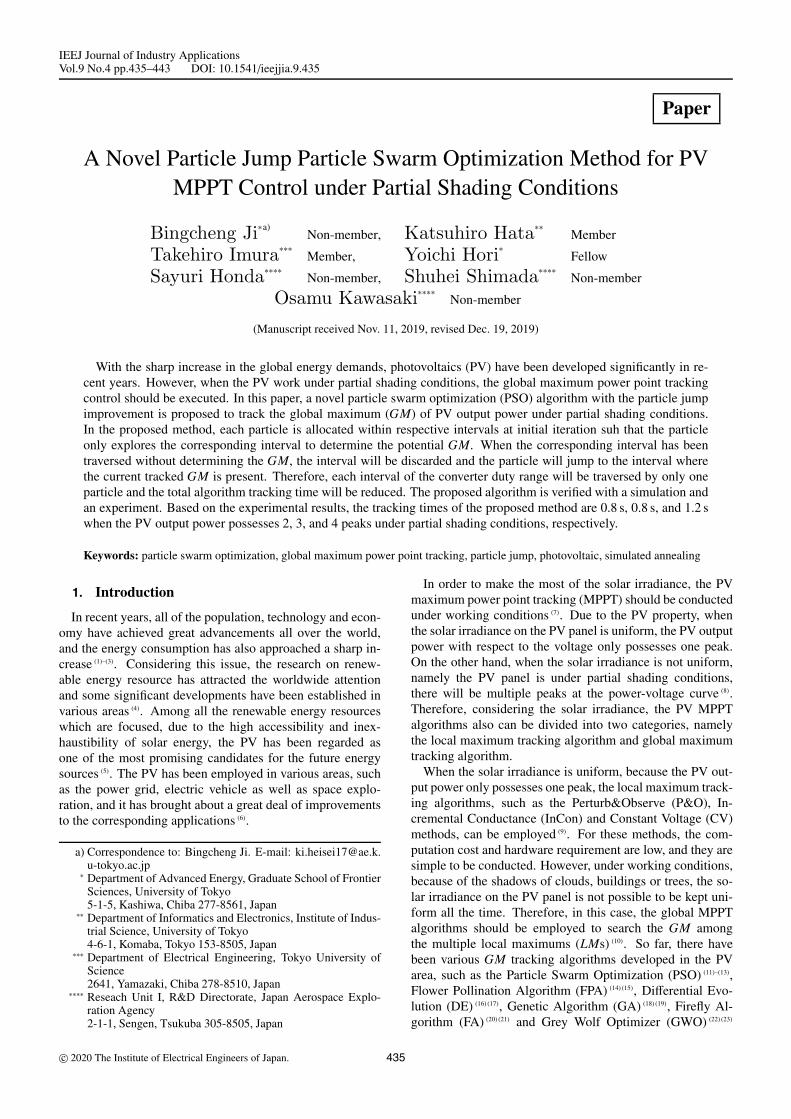
(a)
(b)
Fig. 2. (a) Particle initialization in the converter dutyrange. (b) Particle movement in MPPT process
The algorithm convergence time will be reduced but the prob-ability of tracking the real GM position also decreases; r1 andr2 are the random values following the uniform distributionU(0, 1). In the position update of Eq. (5), with the currentvelocity update, the particle position can be updated.
In each iteration, all the particles will be employed as theconverter duty to obtain the corresponding fitness, namelythe PV power. In the algorithm conducting process, the PMpositions and GM position are updated based on all the par-ticle positions and fitness. Furthermore, with the guidance ofthe personal and GM positions, all the particles will gradu-ally move toward the GM position. After the PSO algorithmiterates enough times, the GM can be effectively tracked.
4. Particle Jump Method Proposal
Because of the capability of tracking the GM, the PSO al-gorithm has been employed into various areas. However, asshown in Eq. (5), the particle position in the PSO algorithmis updated step by step under working conditions. On onehand, because all the particle positions are updated graduallywith velocity increments, the GM position is highly possibleto be tracked with appropriate parameters of w, c1 and c2. Onthe other hand, in general, the velocity increment is alwayslimited within an appropriate range to reduce the algorithmfluctuation, and then the PSO algorithm will take too muchtime to achieve the convergence of all the employed particles.4.1 Invalid Interval Traversal Analysis in PSO Algo-
rithm Due to the PV property, under partial shading con-ditions, the PV output power with respect to voltage is a two-dimension curve, and the particle position is the converterduty varying in the range of (0, 1), as shown in Fig. 2(a).There are 4 particles of a, b, c and d are employed and theGM is at the position of particle c.
In the MPPT process, both particle a and b move to theright side to the global maximum power point and supposethe distance is traversed by particle a and b in successionas shown in Fig. 2(b). However, there are two points shouldbe mentioned: (1) because the initial positions and velocitiesof particle a and b are different, the possibility that particlea and b traverse the duty range dab with the same positionand velocity at each iteration is low enough; (2) the distancedab is traversed twice by the particle a and b, and the former
437 IEEJ Journal IA, Vol.9, No.4, 2020
Particle Jump PSO Algorithm for PV Gloval MPPT Control(Bingcheng Ji et al.)
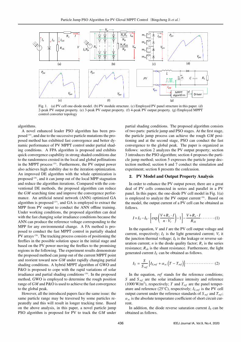
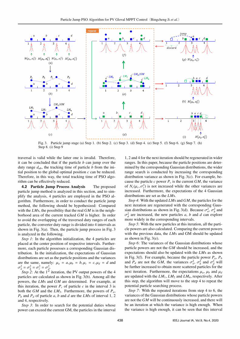
Fig. 3. Particle jump stage (a) Step 1. (b) Step 2. (c) Step 3. (d) Step 4. (e) Step 5. (f) Step 6. (g) Step 7. (h)Step 8. (i) Step 9
traversal is valid while the latter one is invalid. Therefore,it can be concluded that if the particle b can jump over theduty range dab, the tracking time of particle b from the ini-tial position to the global optimal position c can be reduced.Therefore, in this way, the total tracking time of PSO algo-rithm can be effectively reduced.4.2 Particle Jump Process Analysis The proposed
particle jump method is analyzed in this section, and to sim-plify the analysis, 4 particles are employed in the PSO al-gorithm. Furthermore, in order to conduct the particle jumpmethod, the following should be hypothesized: Comparedwith the LMs, the possibility that the real GM is in the neigh-borhood area of the current tracked GM is higher. In orderto avoid the overlapping of the traversed duty ranges of eachparticle, the converter duty range is divided into 4 intervals asshown in Fig. 3(a). Then, the particle jump process in Fig. 3is analyzed in the following.
Step 1: In the algorithm initialization, the 4 particles areplaced at the center position of respective intervals. Further-more, each particle possesses a corresponding Gaussian dis-tribution. In the initialization, the expectations of Gaussiandistributions are set as the particle positions and the variancesare the same, namely: μa = a, μb = b, μc = c, μd = d andσ2
a = σ2b = σ
2c = σ
2d.
Step 2: At the 1st iteration, the PV output powers of the 4particles are calculated as shown in Fig. 3(b). Among all thepowers, the LMs and GM are determined. For example, atthis iteration, the power Pc of particle c in the interval 3 isboth the GM and the LM3. Furthermore, the powers of Pa,Pb and Pd of particle a, b and d are the LMs of interval 1, 2and 4, respectively.
Step 3: In order to search for the potential duties whosepower can exceed the current GM, the particles in the interval
1, 2 and 4 for the next iteration should be regenerated in widerranges. In this paper, because the particle positions are deter-mined by the corresponding Gaussian distributions, the widerrange search is conducted by increasing the correspondingdistribution variance as shown in Fig. 3(c). For example, be-cause the particle c power Pc is the current GM, the varianceof Nc(μc, σ
2c) is not increased while the other variances are
increased. Furthermore, the expectations of the 4 Gaussiandistributions are set as the LMs.
Step 4: With the updated LMs and GM, the particles for thenext iteration are regenerated with the corresponding Gaus-sian distributions as shown in Fig. 3(d). Because σ2
a, σ2b and
σ2d are increased, the new particles a, b and d can explore
more widely in the corresponding intervals.Step 5: With the new particles at this iteration, all the parti-
cle powers are also calculated. Comparing the current powerswith the previous data, the LMs and GM should be updatedas shown in Fig. 3(e).
Step 6: The variances of the Gaussian distributions whoseparticle powers are not the GM should be increased, and theexpectations should also be updated with the LMs as shownin Fig. 3(f). For example, because the particle power Pa, Pb
and Pd are not the GM, the variances σ2a, σ2
b and σ2d will
be further increased to obtain more scattered particles for thenext iteration. Furthermore, the expectations μa, μb and μd
are updated with the LM1, LM2 and LM4, respectively. Afterthis step, the algorithm will move to the step 4 to repeat thepotential particle searching process.
Step 7: With the repeated iterations from step 4 to 6, thevariances of the Gaussian distributions whose particle powersare not the GM will be continuously increased, and there willbe an iteration at which the variance is high enough. Whenthe variance is high enough, it can be seen that this interval
438 IEEJ Journal IA, Vol.9, No.4, 2020
Particle Jump PSO Algorithm for PV Gloval MPPT Control(Bingcheng Ji et al.)
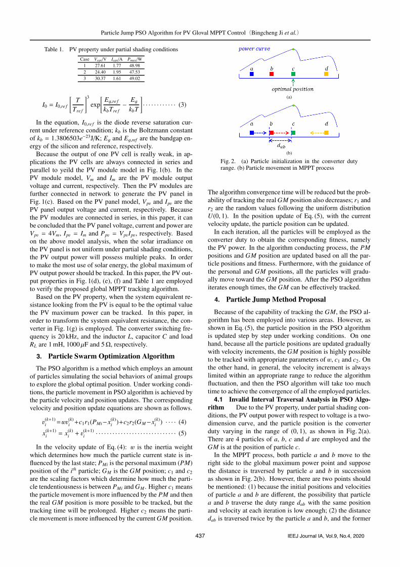
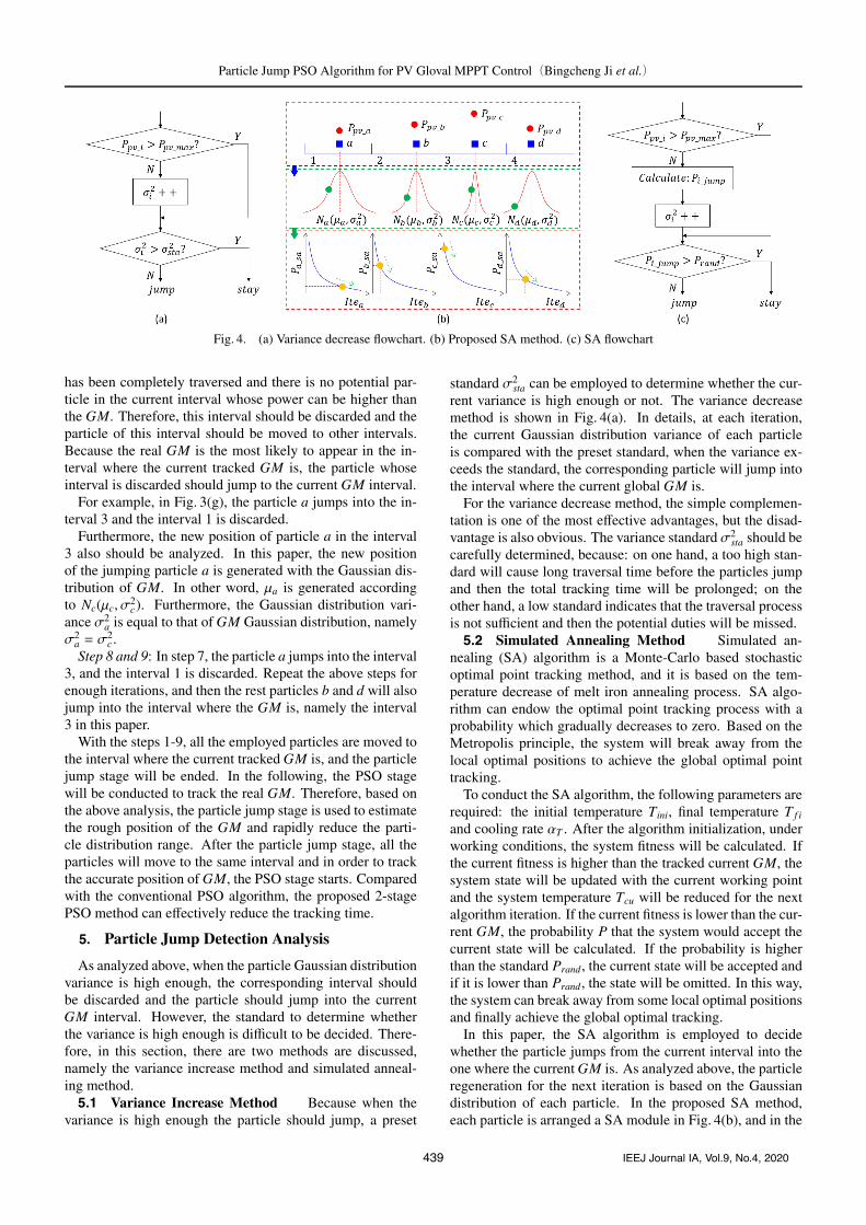
Fig. 4. (a) Variance decrease flowchart. (b) Proposed SA method. (c) SA flowchart
has been completely traversed and there is no potential par-ticle in the current interval whose power can be higher thanthe GM. Therefore, this interval should be discarded and theparticle of this interval should be moved to other intervals.Because the real GM is the most likely to appear in the in-terval where the current tracked GM is, the particle whoseinterval is discarded should jump to the current GM interval.
For example, in Fig. 3(g), the particle a jumps into the in-terval 3 and the interval 1 is discarded.
Furthermore, the new position of particle a in the interval3 also should be analyzed. In this paper, the new positionof the jumping particle a is generated with the Gaussian dis-tribution of GM. In other word, μa is generated accordingto Nc(μc, σ
2c). Furthermore, the Gaussian distribution vari-
ance σ2a is equal to that of GM Gaussian distribution, namely
σ2a = σ
2c .
Step 8 and 9: In step 7, the particle a jumps into the interval3, and the interval 1 is discarded. Repeat the above steps forenough iterations, and then the rest particles b and d will alsojump into the interval where the GM is, namely the interval3 in this paper.
With the steps 1-9, all the employed particles are moved tothe interval where the current tracked GM is, and the particlejump stage will be ended. In the following, the PSO stagewill be conducted to track the real GM. Therefore, based onthe above analysis, the particle jump stage is used to estimatethe rough position of the GM and rapidly reduce the parti-cle distribution range. After the particle jump stage, all theparticles will move to the same interval and in order to trackthe accurate position of GM, the PSO stage starts. Comparedwith the conventional PSO algorithm, the proposed 2-stagePSO method can effectively reduce the tracking time.
5. Particle Jump Detection Analysis
As analyzed above, when the particle Gaussian distributionvariance is high enough, the corresponding interval shouldbe discarded and the particle should jump into the currentGM interval. However, the standard to determine whetherthe variance is high enough is difficult to be decided. There-fore, in this section, there are two methods are discussed,namely the variance increase method and simulated anneal-ing method.5.1 Variance Increase Method Because when the
variance is high enough the particle should jump, a preset
standard σ2sta can be employed to determine whether the cur-
rent variance is high enough or not. The variance decreasemethod is shown in Fig. 4(a). In details, at each iteration,the current Gaussian distribution variance of each particleis compared with the preset standard, when the variance ex-ceeds the standard, the corresponding particle will jump intothe interval where the current global GM is.
For the variance decrease method, the simple complemen-tation is one of the most effective advantages, but the disad-vantage is also obvious. The variance standard σ2
sta should becarefully determined, because: on one hand, a too high stan-dard will cause long traversal time before the particles jumpand then the total tracking time will be prolonged; on theother hand, a low standard indicates that the traversal processis not sufficient and then the potential duties will be missed.5.2 Simulated Annealing Method Simulated an-
nealing (SA) algorithm is a Monte-Carlo based stochasticoptimal point tracking method, and it is based on the tem-perature decrease of melt iron annealing process. SA algo-rithm can endow the optimal point tracking process with aprobability which gradually decreases to zero. Based on theMetropolis principle, the system will break away from thelocal optimal positions to achieve the global optimal pointtracking.
To conduct the SA algorithm, the following parameters arerequired: the initial temperature Tini, final temperature T f i
and cooling rate αT . After the algorithm initialization, underworking conditions, the system fitness will be calculated. Ifthe current fitness is higher than the tracked current GM, thesystem state will be updated with the current working pointand the system temperature Tcu will be reduced for the nextalgorithm iteration. If the current fitness is lower than the cur-rent GM, the probability P that the system would accept thecurrent state will be calculated. If the probability is higherthan the standard Prand , the current state will be accepted andif it is lower than Prand, the state will be omitted. In this way,the system can break away from some local optimal positionsand finally achieve the global optimal tracking.
In this paper, the SA algorithm is employed to decidewhether the particle jumps from the current interval into theone where the current GM is. As analyzed above, the particleregeneration for the next iteration is based on the Gaussiandistribution of each particle. In the proposed SA method,each particle is arranged a SA module in Fig. 4(b), and in the
439 IEEJ Journal IA, Vol.9, No.4, 2020
Particle Jump PSO Algorithm for PV Gloval MPPT Control(Bingcheng Ji et al.)
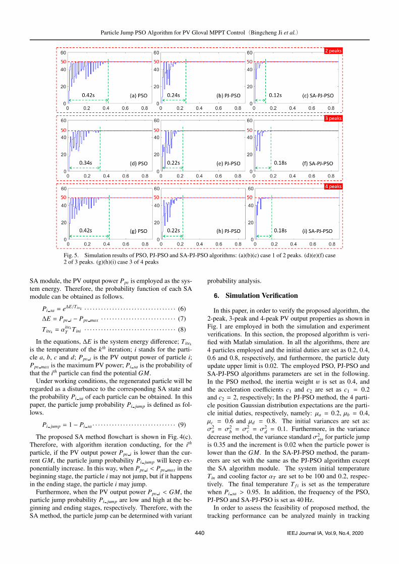
Fig. 5. Simulation results of PSO, PJ-PSO and SA-PJ-PSO algorithms: (a)(b)(c) case 1 of 2 peaks. (d)(e)(f) case2 of 3 peaks. (g)(h)(i) case 3 of 4 peaks
SA module, the PV output power Ppv is employed as the sys-tem energy. Therefore, the probability function of each SAmodule can be obtained as follows.
Pi sa = eΔE/Titek · · · · · · · · · · · · · · · · · · · · · · · · · · · · · · · · · (6)
ΔE = Ppv i − Ppv max · · · · · · · · · · · · · · · · · · · · · · · · · · · (7)
Titek = αitekT Tini · · · · · · · · · · · · · · · · · · · · · · · · · · · · · · · · · (8)
In the equations, ΔE is the system energy difference; Titek
is the temperature of the kth iteration; i stands for the parti-cle a, b, c and d; Ppv i is the PV output power of particle i;Ppv max is the maximum PV power; Pi sa is the probability ofthat the ith particle can find the potential GM.
Under working conditions, the regenerated particle will beregarded as a disturbance to the corresponding SA state andthe probability Pi sa of each particle can be obtained. In thispaper, the particle jump probability Pi jump is defined as fol-lows.
Pi jump = 1 − Pi sa · · · · · · · · · · · · · · · · · · · · · · · · · · · · · · (9)
The proposed SA method flowchart is shown in Fig. 4(c).Therefore, with algorithm iteration conducting, for the ith
particle, if the PV output power Ppv i is lower than the cur-rent GM, the particle jump probability Pi jump will keep ex-ponentially increase. In this way, when Ppv i < Ppv max in thebeginning stage, the particle i may not jump, but if it happensin the ending stage, the particle i may jump.
Furthermore, when the PV output power Ppv i < GM, theparticle jump probability Pi jump are low and high at the be-ginning and ending stages, respectively. Therefore, with theSA method, the particle jump can be determined with variant
probability analysis.
6. Simulation Verification
In this paper, in order to verify the proposed algorithm, the2-peak, 3-peak and 4-peak PV output properties as shown inFig. 1 are employed in both the simulation and experimentverifications. In this section, the proposed algorithm is veri-fied with Matlab simulation. In all the algorithms, there are4 particles employed and the initial duties are set as 0.2, 0.4,0.6 and 0.8, respectively, and furthermore, the particle dutyupdate upper limit is 0.02. The employed PSO, PJ-PSO andSA-PJ-PSO algorithms parameters are set in the following.In the PSO method, the inertia weight w is set as 0.4, andthe acceleration coefficients c1 and c2 are set as c1 = 0.2and c2 = 2, respectively; In the PJ-PSO method, the 4 parti-cle position Gaussian distribution expectations are the parti-cle initial duties, respectively, namely: μa = 0.2, μb = 0.4,μc = 0.6 and μd = 0.8. The initial variances are set as:σ2
a = σ2b = σ
2c = σ
2d = 0.1. Furthermore, in the variance
decrease method, the variance standard σ2sta for particle jump
is 0.35 and the increment is 0.02 when the particle power islower than the GM. In the SA-PJ-PSO method, the param-eters are set with the same as the PJ-PSO algorithm exceptthe SA algorithm module. The system initial temperatureTin and cooling factor αT are set to be 100 and 0.2, respec-tively. The final temperature T f i is set as the temperaturewhen Pi sa > 0.95. In addition, the frequency of the PSO,PJ-PSO and SA-PJ-PSO is set as 40 Hz.
In order to assess the feasibility of proposed method, thetracking performance can be analyzed mainly in tracking
440 IEEJ Journal IA, Vol.9, No.4, 2020
Particle Jump PSO Algorithm for PV Gloval MPPT Control(Bingcheng Ji et al.)
time and accuracy aspects. When the PV output power fluc-tuation is limited within 5%, the MPPT control is regarded tohave been achieved. The time from the moment when the al-gorithm starts and to the moment when the MPPT is achievedis defined as the algorithm tracking time. Furthermore, theratio between the power Psta in the stable state and theorymaximum power Pmax is taken as the tracking efficiency ηtra.
The simulation results are shown in Fig. 5 and Table 2, andbased on the results, the MPPT control has been achievedin all the cases. When the PV output power possesses 2peaks with respect to voltage, the MPPT control is achevedwithin 0.42 s, 0.24 s and 0.12 s in the methods of PSO, PJ-PSO and SA-PJ-PSO, respectively. Furthermore, the MPPTefficiency ηtra is 99.78%, 99.82% and 99.83%, respectively.Furthermore, the PV output power of PSO method varies in-tensely in the tracking process, and this is because the par-ticle position in the PSO algorithm is updated gradually it-eration by iteration. On the other hand, the power variationof the proposed SA-PJ-PSO algorithm is much less intensedue to the fast convergence of particles with the assistance
Table 2. Simulation results of 3 methodsCase Method Psta/W ηtra Iteration Time/s
1PSO 48.87 99.78% 17 0.42
PJ-PSO 48.89 99.82% 10 0.24SA-PJ-PSO 48.90 99.83% 5 0.12
2PSO 47.43 99.79% 14 0.34
PJ-PSO 47.45 99.83% 9 0.22SA-PJ-PSO 47.46 99.85% 8 0.18
3PSO 48.89 99.73% 17 0.42
PJ-PSO 48.90 99.76% 9 0.22SA-PJ-PSO 48.93 99.82% 8 0.18
of particle jump and simulated annealing. In the MPPT sim-ulation of 3 peaks, the tracking time of 3 methods is 0.34 s,0.22 s and 0.18 s, respectively. Furthermore, the tracking ef-ficiency ηtra is 99.79%, 99.83% and 99.85%, respectively. Inthe MPPT simulation of 4 peaks, the tracking time of 3 meth-ods is 0.42 s, 0.22 s and 0.18 s, respectively. Furthermore, thetracking efficiency ηtra is 99.73%, 99.76% and 99.82%, re-spectively.
Therefore, in case 1, 2 and 3, the proposed SA-PJ-PSOmethod has achieved both the shortest MPPT time and theleast PV output power fluctuation in the tracking process.
7. Experiment Verification
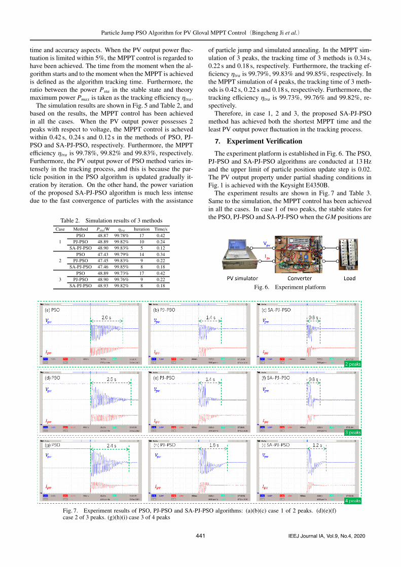
The experiment platform is established in Fig. 6. The PSO,PJ-PSO and SA-PJ-PSO algorithms are conducted at 13 Hzand the upper limit of particle position update step is 0.02.The PV output property under partial shading conditions inFig. 1 is achieved with the Keysight E4350B.
The experiment results are shown in Fig. 7 and Table 3.Same to the simulation, the MPPT control has been achievedin all the cases. In case 1 of two peaks, the stable states forthe PSO, PJ-PSO and SA-PJ-PSO when the GM positions are
Fig. 6. Experiment platform
Fig. 7. Experiment results of PSO, PJ-PSO and SA-PJ-PSO algorithms: (a)(b)(c) case 1 of 2 peaks. (d)(e)(f)case 2 of 3 peaks. (g)(h)(i) case 3 of 4 peaks
441 IEEJ Journal IA, Vol.9, No.4, 2020
Particle Jump PSO Algorithm for PV Gloval MPPT Control(Bingcheng Ji et al.)
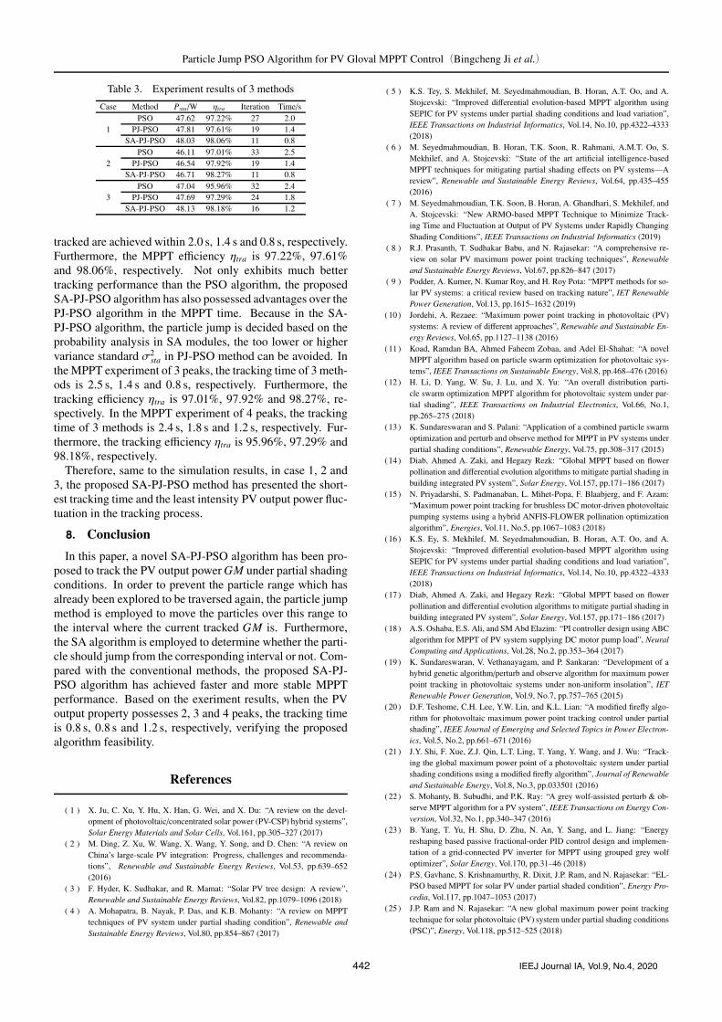
Table 3. Experiment results of 3 methods
Case Method Psta/W ηtra Iteration Time/s
1PSO 47.62 97.22% 27 2.0
PJ-PSO 47.81 97.61% 19 1.4SA-PJ-PSO 48.03 98.06% 11 0.8
2PSO 46.11 97.01% 33 2.5
PJ-PSO 46.54 97.92% 19 1.4SA-PJ-PSO 46.71 98.27% 11 0.8
3PSO 47.04 95.96% 32 2.4
PJ-PSO 47.69 97.29% 24 1.8SA-PJ-PSO 48.13 98.18% 16 1.2
tracked are achieved within 2.0 s, 1.4 s and 0.8 s, respectively.Furthermore, the MPPT efficiency ηtra is 97.22%, 97.61%and 98.06%, respectively. Not only exhibits much bettertracking performance than the PSO algorithm, the proposedSA-PJ-PSO algorithm has also possessed advantages over thePJ-PSO algorithm in the MPPT time. Because in the SA-PJ-PSO algorithm, the particle jump is decided based on theprobability analysis in SA modules, the too lower or highervariance standard σ2
sta in PJ-PSO method can be avoided. Inthe MPPT experiment of 3 peaks, the tracking time of 3 meth-ods is 2.5 s, 1.4 s and 0.8 s, respectively. Furthermore, thetracking efficiency ηtra is 97.01%, 97.92% and 98.27%, re-spectively. In the MPPT experiment of 4 peaks, the trackingtime of 3 methods is 2.4 s, 1.8 s and 1.2 s, respectively. Fur-thermore, the tracking efficiency ηtra is 95.96%, 97.29% and98.18%, respectively.
Therefore, same to the simulation results, in case 1, 2 and3, the proposed SA-PJ-PSO method has presented the short-est tracking time and the least intensity PV output power fluc-tuation in the tracking process.
8. Conclusion
In this paper, a novel SA-PJ-PSO algorithm has been pro-posed to track the PV output power GM under partial shadingconditions. In order to prevent the particle range which hasalready been explored to be traversed again, the particle jumpmethod is employed to move the particles over this range tothe interval where the current tracked GM is. Furthermore,the SA algorithm is employed to determine whether the parti-cle should jump from the corresponding interval or not. Com-pared with the conventional methods, the proposed SA-PJ-PSO algorithm has achieved faster and more stable MPPTperformance. Based on the exeriment results, when the PVoutput property possesses 2, 3 and 4 peaks, the tracking timeis 0.8 s, 0.8 s and 1.2 s, respectively, verifying the proposedalgorithm feasibility.
References
( 1 ) X. Ju, C. Xu, Y. Hu, X. Han, G. Wei, and X. Du: “A review on the devel-opment of photovoltaic/concentrated solar power (PV-CSP) hybrid systems”,Solar Energy Materials and Solar Cells, Vol.161, pp.305–327 (2017)
( 2 ) M. Ding, Z. Xu, W. Wang, X. Wang, Y. Song, and D. Chen: “A review onChina’s large-scale PV integration: Progress, challenges and recommenda-tions”, Renewable and Sustainable Energy Reviews, Vol.53, pp.639–652(2016)
( 3 ) F. Hyder, K. Sudhakar, and R. Mamat: “Solar PV tree design: A review”,Renewable and Sustainable Energy Reviews, Vol.82, pp.1079–1096 (2018)
( 4 ) A. Mohapatra, B. Nayak, P. Das, and K.B. Mohanty: “A review on MPPTtechniques of PV system under partial shading condition”, Renewable andSustainable Energy Reviews, Vol.80, pp.854–867 (2017)
( 5 ) K.S. Tey, S. Mekhilef, M. Seyedmahmoudian, B. Horan, A.T. Oo, and A.Stojcevski: “Improved differential evolution-based MPPT algorithm usingSEPIC for PV systems under partial shading conditions and load variation”,IEEE Transactions on Industrial Informatics, Vol.14, No.10, pp.4322–4333(2018)
( 6 ) M. Seyedmahmoudian, B. Horan, T.K. Soon, R. Rahmani, A.M.T. Oo, S.Mekhilef, and A. Stojcevski: “State of the art artificial intelligence-basedMPPT techniques for mitigating partial shading effects on PV systems—Areview”, Renewable and Sustainable Energy Reviews, Vol.64, pp.435–455(2016)
( 7 ) M. Seyedmahmoudian, T.K. Soon, B. Horan, A. Ghandhari, S. Mekhilef, andA. Stojcevski: “New ARMO-based MPPT Technique to Minimize Track-ing Time and Fluctuation at Output of PV Systems under Rapidly ChangingShading Conditions”, IEEE Transactions on Industrial Informatics (2019)
( 8 ) R.J. Prasanth, T. Sudhakar Babu, and N. Rajasekar: “A comprehensive re-view on solar PV maximum power point tracking techniques”, Renewableand Sustainable Energy Reviews, Vol.67, pp.826–847 (2017)
( 9 ) Podder, A. Kumer, N. Kumar Roy, and H. Roy Pota: “MPPT methods for so-lar PV systems: a critical review based on tracking nature”, IET RenewablePower Generation, Vol.13, pp.1615–1632 (2019)
(10) Jordehi, A. Rezaee: “Maximum power point tracking in photovoltaic (PV)systems: A review of different approaches”, Renewable and Sustainable En-ergy Reviews, Vol.65, pp.1127–1138 (2016)
(11) Koad, Ramdan BA, Ahmed Faheem Zobaa, and Adel El-Shahat: “A novelMPPT algorithm based on particle swarm optimization for photovoltaic sys-tems”, IEEE Transactions on Sustainable Energy, Vol.8, pp.468–476 (2016)
(12) H. Li, D. Yang, W. Su, J. Lu, and X. Yu: “An overall distribution parti-cle swarm optimization MPPT algorithm for photovoltaic system under par-tial shading”, IEEE Transactions on Industrial Electronics, Vol.66, No.1,pp.265–275 (2018)
(13) K. Sundareswaran and S. Palani: “Application of a combined particle swarmoptimization and perturb and observe method for MPPT in PV systems underpartial shading conditions”, Renewable Energy, Vol.75, pp.308–317 (2015)
(14) Diab, Ahmed A. Zaki, and Hegazy Rezk: “Global MPPT based on flowerpollination and differential evolution algorithms to mitigate partial shading inbuilding integrated PV system”, Solar Energy, Vol.157, pp.171–186 (2017)
(15) N. Priyadarshi, S. Padmanaban, L. Mihet-Popa, F. Blaabjerg, and F. Azam:“Maximum power point tracking for brushless DC motor-driven photovoltaicpumping systems using a hybrid ANFIS-FLOWER pollination optimizationalgorithm”, Energies, Vol.11, No.5, pp.1067–1083 (2018)
(16) K.S. Ey, S. Mekhilef, M. Seyedmahmoudian, B. Horan, A.T. Oo, and A.Stojcevski: “Improved differential evolution-based MPPT algorithm usingSEPIC for PV systems under partial shading conditions and load variation”,IEEE Transactions on Industrial Informatics, Vol.14, No.10, pp.4322–4333(2018)
(17) Diab, Ahmed A. Zaki, and Hegazy Rezk: “Global MPPT based on flowerpollination and differential evolution algorithms to mitigate partial shading inbuilding integrated PV system”, Solar Energy, Vol.157, pp.171–186 (2017)
(18) A.S. Oshaba, E.S. Ali, and SM Abd Elazim: “PI controller design using ABCalgorithm for MPPT of PV system supplying DC motor pump load”, NeuralComputing and Applications, Vol.28, No.2, pp.353–364 (2017)
(19) K. Sundareswaran, V. Vethanayagam, and P. Sankaran: “Development of ahybrid genetic algorithm/perturb and observe algorithm for maximum powerpoint tracking in photovoltaic systems under non-uniform insolation”, IETRenewable Power Generation, Vol.9, No.7, pp.757–765 (2015)
(20) D.F. Teshome, C.H. Lee, Y.W. Lin, and K.L. Lian: “A modified firefly algo-rithm for photovoltaic maximum power point tracking control under partialshading”, IEEE Journal of Emerging and Selected Topics in Power Electron-ics, Vol.5, No.2, pp.661–671 (2016)
(21) J.Y. Shi, F. Xue, Z.J. Qin, L.T. Ling, T. Yang, Y. Wang, and J. Wu: “Track-ing the global maximum power point of a photovoltaic system under partialshading conditions using a modified firefly algorithm”, Journal of Renewableand Sustainable Energy, Vol.8, No.3, pp.033501 (2016)
(22) S. Mohanty, B. Subudhi, and P.K. Ray: “A grey wolf-assisted perturb & ob-serve MPPT algorithm for a PV system”, IEEE Transactions on Energy Con-version, Vol.32, No.1, pp.340–347 (2016)
(23) B. Yang, T. Yu, H. Shu, D. Zhu, N. An, Y. Sang, and L. Jiang: “Energyreshaping based passive fractional-order PID control design and implemen-tation of a grid-connected PV inverter for MPPT using grouped grey wolfoptimizer”, Solar Energy, Vol.170, pp.31–46 (2018)
(24) P.S. Gavhane, S. Krishnamurthy, R. Dixit, J.P. Ram, and N. Rajasekar: “EL-PSO based MPPT for solar PV under partial shaded condition”, Energy Pro-cedia, Vol.117, pp.1047–1053 (2017)
(25) J.P. Ram and N. Rajasekar: “A new global maximum power point trackingtechnique for solar photovoltaic (PV) system under partial shading conditions(PSC)”, Energy, Vol.118, pp.512–525 (2018)
442 IEEJ Journal IA, Vol.9, No.4, 2020

Particle Jump PSO Algorithm for PV Gloval MPPT Control(Bingcheng Ji et al.)
(26 ) N. Kumar, I. Hussain, B. Singh, and B.K. Panigrahi: “MPPT in dynamiccondition of partially shaded PV system by using WODE technique”, IEEETransactions on Sustainable Energy, Vol.8, No.3, pp.1204–1214 (2017)
(27) R. Ramaprabha, V. Gothandaraman, K. Kanimozhi, R. Divya, and B.L.Mathur: “Maximum power point tracking using GA-optimized artificial neu-ral network for solar PV system”, 2011 1st International Conference on Elec-trical Energy Systems. IEEE (2011)
(28) K. Sundareswaran, P. Sankar, and P. Sankaran: “MPPT of PV systems un-der partial shaded conditions through a colony of flashing fireflies”, IEEETransactions on Energy Conversion, Vol.29, pp.463–472 (2014)
(29) S. Mohanty, B. Subudhi, and P.K. Ray: “A grey wolf-assisted perturb & ob-serve MPPT algorithm for a PV system”, IEEE Transactions on Energy Con-version, Vol.32, No.1, pp.340–347 (2016)
(30) A. Laudani, F.R. Fulginei, and A. Salvini: “Identification of the one-diode model for photovoltaic modules from datasheet values”, Solar Energy,Vol.108, pp.432–446 (2014)
Bingcheng Ji (Non-member) received the B.S. and M.S. degreesin electrical engineering from Dalian University ofTechnology, Dalian, China, in 2011 and 2015, re-spectively. He is currently working toward the Ph.D.degree in the Graduate School of Frontier Sciences,The University of Tokyo, Chiba, Japan. His researchinterests include wireless power transfer, PV MPPTcontrol and power electronics.
Katsuhiro Hata (Member) received the M.S. and Ph.D. degrees fromthe University of Tokyo in 2015 and 2018, respec-tively. He is currently a Research Associate with theDepartment of Informatics and Electronics, Instituteof Industrial Science, the University of Tokyo. Hisresearch interests include power electronics, wirelesspower transfer, and e-mobility for transportation. Heis a member of the Institute of Electrical and Elec-tronics Engineers, the Institute of Electronics, Infor-mation and Communication Engineers, and the Soci-
ety of Automotive Engineers of Japan.
Takehiro Imura (Member) received the B.S. degrees in electricaland electronics engineering from Sophia University,Tokyo, Japan, in 2005, and the M.E. degree in elec-tronic engineering and the Ph.D. degree in electricalengineering from the University of Tokyo, in 2007and 2010, respectively. He joined the Department ofAdvanced Energy, Graduate School of Frontier Sci-ences, the University of Tokyo, as a Research Asso-ciate in 2010, he moved to the Department of Elec-trical Engineering and Information Systems, Gradu-
ate School of Engineering, the University of Tokyo as a Project Lecturer.In 2019, he moved to the Department of Electrical Engineering, Faculty ofScience and Technology, Tokyo University of Science, as an Associate Pro-fessor. He is currently investigating wireless power transfer for EV usingmagnetic resonance coupling.
Yoichi Hori (Fellow) received the B.S., M.S., and Ph.D. degrees inelectrical engineering from the University of Tokyo,Tokyo, Japan, in 1978, 1980, and 1983, respectively.In 2000, he became a Professor at the Universityof Tokyo, and where in 2008, he moved to the De-partment of Advanced Energy, Graduate School ofFrontier Sciences. His research fields are controltheory and its industrial applications in motion con-trol, mechatronics, robotics, and electric vehicles.Dr. Hori received the Best Transactions Paper Award
from the IEEE Transactions on Industrial Electronics in 1993 and 2001, andthe 2011 Achievement Award from the Institute of Electrical Engineers ofJapan (IEE-Japan). He was the President of the Industry Applications So-ciety the IEEJ, the President of Capacitors Forum, and the Chairman of theMotor Technology Symposium of the Japan Manahement Association, andthe Director on Technological Develipment of SAEJapan.
Sayuri Honda (Non-member) received the B.S. and M.S. degrees inelectrical engineering from The University of Tokyoin 2013 and 2015 respectively. She is currently re-searching power control system of the spacecrafts inJAXA R&D directorate. Her main research theme iswireless power transmission system for spacecrafts.
Shuhei Shimada (Non-member) received the B.S. and M.S. degreesin electrical engineering from Tokyo University ofScience in 2007 and 2009 respectively. He is cur-rently developing satellite power systems and smallbatteries in JAXA R&D directorate. He researcheswireless power supply system for spacecraft.
Osama Kawasaki (Non-member) received the B.S. and M.S. degreesin nuclear engineering from the Osaka University,Osaka, Japan, in 1989 and 1991 respectively. After heentered JAXA, he engaged in the development of theelectrical power system of Japanese unmanned trans-fer vehicle to the International Space Station, HTV,and the asteroid explorer, Hayabusa2.He currentlyresearches the space application of wireless powertransfer technique in R&D directorate.
443 IEEJ Journal IA, Vol.9, No.4, 2020