Embed Size (px)
Citation preview
A Novel Modelling and Controlling of Distributed Power Flow Controller (DPFC) Base on PSO Algorithm 1
A Novel Modelling and Controlling ofDistributed Power Flow Controller (DPFC) Base
on PSO Algorithm
Ali Ajami1 , Behrouz Soulat2 , and Amin Safari3 , Non-members
ABSTRACT
This paper focuses mainly on the state mod-elling controlling of a new FACTS device named Dis-tributed Power Flow Controller (DPFC). The pa-per also discusses the role and function of DPFCin power flow controlling together with its economicevaluation. DPFC is one of the Distributed FACTS(D-FACTS) devices. Its function is similar to thatof UPFC but instead of one series converters, sev-eral low power series converters are used in DPFC.Therefore, DPFC includes multiple series convertersand one shunt converter without common dc link.This eventually enables the DPFC to fully controlall power system parameters. It, also, increases thereliability of the device and reduces its cost simul-taneously. In this study a novel current injectionmodel of DPFC is presented. The suggested modelis suitable for steady state and stability studies. Touse the presented model, a proper control system isneeded. In this paper the PSO algorithm is used foroptimal designing of controller parameters. Applica-tion of DPFC in different operating conditions andfailure in series converters are simulated with Mat-lab/Simulink software .The presented control systemenables the DPFC to control the active and reactivepower flow at the transmission line independently. Inconclusion, the resented simulation results show thevalidity and effectiveness of suggested modelling andcontrol system of DPFC for power flow controlling.
Keywords: D-FACTS, DPFC, UPFC, Power FlowController, Current Injection Model
1. INTRODUCTION
In recent years because of increasing demand ofelectric power consumption, the necessity of devel-opment in generation units and power transmissionlines are more felt. But to accomplish it, there aresome problems such as nature pollution and Con-struction cost of new generation units and transmis-
Manuscript received on July 9, 2012 ; revised on November2, 2012.1 The author is with Electrical Engineering Department,
Azarbaiajn Shahid Madani University, Tabriz, Iran., E-mail:[email protected],3 The authors are with Electrical Engineering Department,
Ahar Branch, Islamic Azad University, Ahar, Iran., E-mail:[email protected] and [email protected]
sion network.These problems cause that the powersystems engineers to reconsider power systems de-signing and employ the flexible AC transmission sys-tems (FACTS). The concept of FACTS based on thepower electronics converters which has introducedmany possibilities for fast controlling and optimiza-tion of electric power flow in transmission lines andimproving the power system stability [1].
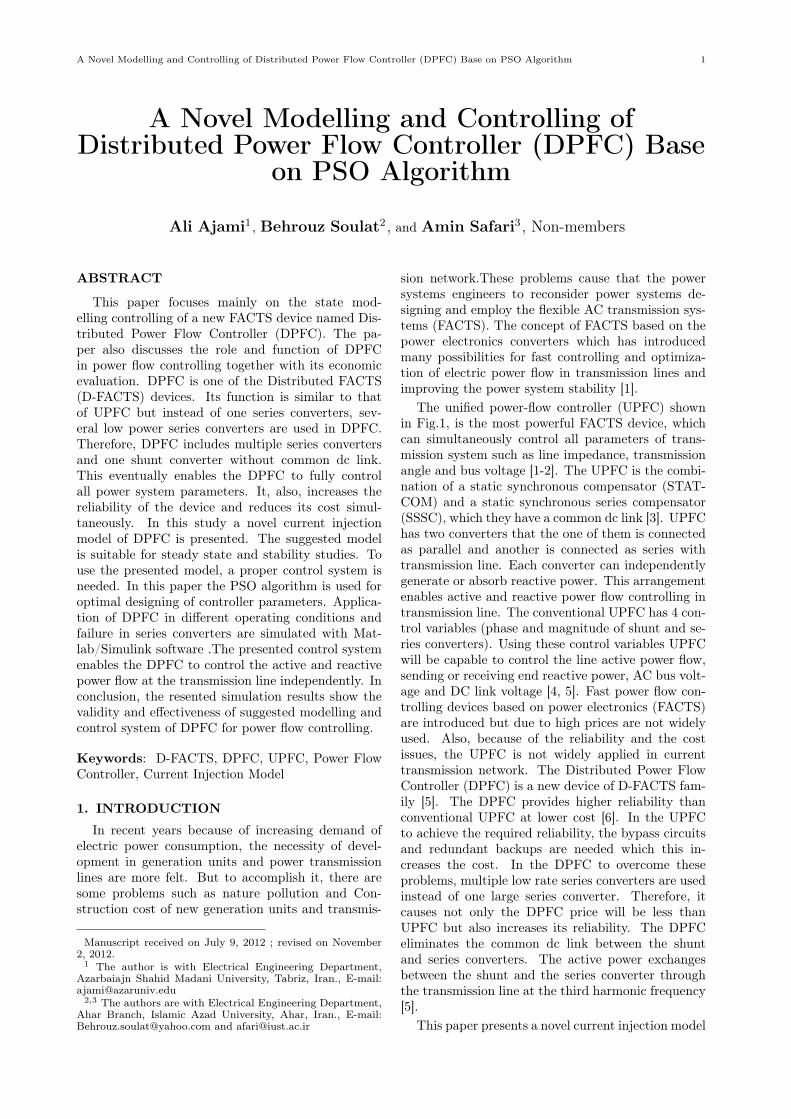
The unified power-flow controller (UPFC) shownin Fig.1, is the most powerful FACTS device, whichcan simultaneously control all parameters of trans-mission system such as line impedance, transmissionangle and bus voltage [1-2]. The UPFC is the combi-nation of a static synchronous compensator (STAT-COM) and a static synchronous series compensator(SSSC), which they have a common dc link [3]. UPFChas two converters that the one of them is connectedas parallel and another is connected as series withtransmission line. Each converter can independentlygenerate or absorb reactive power. This arrangementenables active and reactive power flow controlling intransmission line. The conventional UPFC has 4 con-trol variables (phase and magnitude of shunt and se-ries converters). Using these control variables UPFCwill be capable to control the line active power flow,sending or receiving end reactive power, AC bus volt-age and DC link voltage [4, 5]. Fast power flow con-trolling devices based on power electronics (FACTS)are introduced but due to high prices are not widelyused. Also, because of the reliability and the costissues, the UPFC is not widely applied in currenttransmission network. The Distributed Power FlowController (DPFC) is a new device of D-FACTS fam-ily [5]. The DPFC provides higher reliability thanconventional UPFC at lower cost [6]. In the UPFCto achieve the required reliability, the bypass circuitsand redundant backups are needed which this in-creases the cost. In the DPFC to overcome theseproblems, multiple low rate series converters are usedinstead of one large series converter. Therefore, itcauses not only the DPFC price will be less thanUPFC but also increases its reliability. The DPFCeliminates the common dc link between the shuntand series converters. The active power exchangesbetween the shunt and the series converter throughthe transmission line at the third harmonic frequency[5].
This paper presents a novel current injection model
2 ECTI TRANSACTIONS ON ELECTRICAL ENG., ELECTRONICS, AND COMMUNICATIONS VOL.11, NO.1 February 2013
for DPFC. The suggested model is suitable for steadystate and stability studies. To use the presentedmodel, a proper control system is need. In this paperthe PSO algorithm is used for optimum designing ofcontroller parameters. The presented control systemenables the DPFC to independent control of activeand reactive power flow at the transmission line. Fi-nally, the simulation results are presented.
Fig.1: General configuration of UPFC.
2. DPFC STRUCTURE
According to Fig.2, two changes should be appliedto UPFC in order to increasing the reliability and toreduce the cost. First, eliminating the common dclink of the UPFC and second distributing the seriesconverter. With these changes, the new FACTS de-vice, that is called DPFC, is achieved [6].
Fig.2: Transformation from the UPFC to theDPFC.
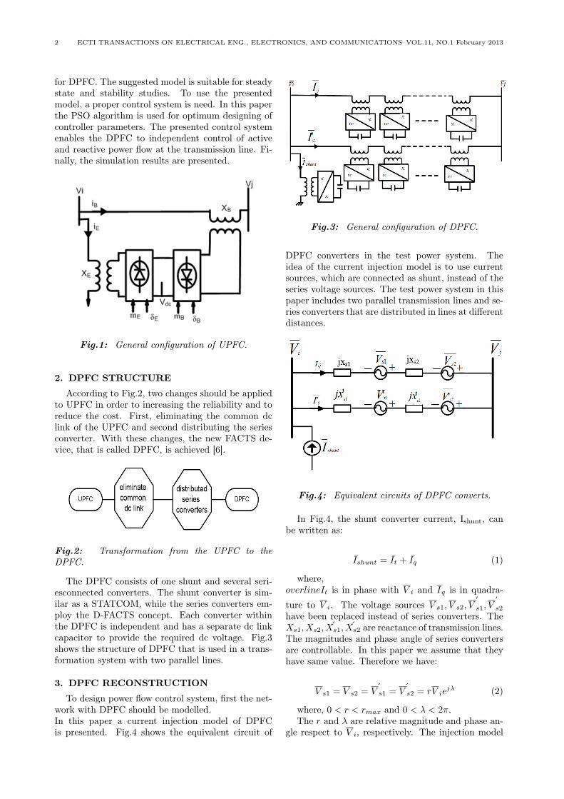
The DPFC consists of one shunt and several seri-esconnected converters. The shunt converter is sim-ilar as a STATCOM, while the series converters em-ploy the D-FACTS concept. Each converter withinthe DPFC is independent and has a separate dc linkcapacitor to provide the required dc voltage. Fig.3shows the structure of DPFC that is used in a trans-formation system with two parallel lines.
3. DPFC RECONSTRUCTION
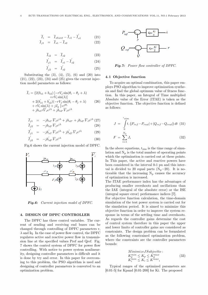
To design power flow control system, first the net-work with DPFC should be modelled.In this paper a current injection model of DPFCis presented. Fig.4 shows the equivalent circuit of
Fig.3: General configuration of DPFC.
DPFC converters in the test power system. Theidea of the current injection model is to use currentsources, which are connected as shunt, instead of theseries voltage sources. The test power system in thispaper includes two parallel transmission lines and se-ries converters that are distributed in lines at differentdistances.
Fig.4: Equivalent circuits of DPFC converts.
In Fig.4, the shunt converter current, Ishunt, canbe written as:
Ishunt = It + Iq (1)
where,overlineIt is in phase with V i and Iq is in quadra-
ture to V i. The voltage sources V s1, V s2, V′
s1, V′
s2
have been replaced instead of series converters. TheXs1, Xs2, Xs1, Xs2 are reactance of transmission lines.The magnitudes and phase angle of series convertersare controllable. In this paper we assume that theyhave same value. Therefore we have:
V s1 = V s2 = ´V s1 = ´V s2 = rV iejλ (2)
where, 0 < r < rmax and 0 < λ < 2π.The r and λ are relative magnitude and phase an-
gle respect to V i, respectively. The injection model

A Novel Modelling and Controlling of Distributed Power Flow Controller (DPFC) Base on PSO Algorithm 3
is obtained by replacing the voltage sources with thecurrent sources as shown in Fig. 5 and we have:
Is1 =V s1
jxs1= −jbs1rV ie
jλ (3)
Is2 =V s2
jxs2= −jbs2rV ie
jλ (4)
I′
s1 =V
′
s1
jx′s1
= −jb′s1rV iejλ (5)
I′
s2 =V
′
s2
jx′s2
= −jb′s2rV iejλ (6)
Where, bs1 = 1/xs1, bs2 = 1/xs2, b′s1 = 1/x′
s1 andb′s2 = 1/x′
s2.
Fig.5: Representation of series voltage sources bycurrent sources.
The active power supplied by the shunt currentsource can be calculated as follows:
Pshunt = Re[V i(−I∗shunt)
]= −ViIt (7)
With the neglected DPFC losses we have:
Pshunt = Pseries = Ps1 + Ps2 + P′
s1 + P′
s2 (8)
The apparent power supplied by the series con-verter V s1 can be calculated as:
Ss1=V s1I∗ij=rV ie
jλ
[V i+V s1+V s2−V j
j(xs1+xs2)
]∗= rV ie
jλ
[V i + rV ie
jλ + rV iejλ − V j
j(xs1 + xs2)
]∗ (9)
Ss1 = Ps1 + jQs1 (10)
From (9) and (10) the exchanged active and reac-tive powerflow Converter V s1 are distinguished as:
Ps1 = (bs1 + bs2) [rViVj sin(θi − θj + λ)−rV 2
i sin(λ)] (11)
Qs1=(bs1+bs2)[rV 2
i Vj cos(λ) + 2r2v2i−rV 2
i vj cos(θi − θj + λ)] (12)
With attention the above equations the exchangedactive and reactive power by converters V s2, V
′
s1 andV
′
s2 are calculated as:
Ps2 = (bs1 + bs2) [rViVj sin(θi − θj + λ)−rV 2
i sin(λ)] (13)
Qs2=(bs1+bs2)[rV 2
i Vj cos(λ) + 2r2v2i−rV 2
i vj cos(θi − θj + λ)] (14)
P′
s1 = (b′
s1 + b′
s2) [rViVj sin(θi − θj + λ)−rV 2
i sin(λ)] (15)
Q′
s1=(b′
s1+b′
s2)[rV 2
i Vj cos(λ) + 2r2v2i−rV 2
i vj cos(θi − θj + λ)] (16)
P′
s2 = (b′
s1 + b′
s2) [rViVj sin(θi − θj + λ)−rV 2
i sin(λ)] (17)
Q′
s2=(b′
s1+b′
s2)[rV 2
i Vj cos(λ) + 2r2v2i−rV 2
i vj cos(θi − θj + λ)] (18)
Substitution of (7), (11), (13), (15) and (17) into(8) gives:
It=2(bs1+bs2)−[−rVjsin(θi−θj+λ)+rVisin(λ)]
+2(b′
s1+b′
s2)[−rVjsin(θi−θj+λ)+rVisin(λ)](19)
Finally, the shunt converter current can be ob-tained as:
Ishunt = It + Iq = (It + jIq)ejθi
=(2(bs1+bs2)[−rVjsin(θi−θj+λ)+rVisin(λ)]
+2(b′
s1 + b′
s2) [−rVj sin(θi − θj + λ)+rVi sin(λ)) + jIq] e
jθi
(20)
Thus, the current injection model of DPFC is ob-tained as follows:
4 ECTI TRANSACTIONS ON ELECTRICAL ENG., ELECTRONICS, AND COMMUNICATIONS VOL.11, NO.1 February 2013
Ii = Ishunt − Is1 − I′
s1 (21)Ij1 = Is1 − Is2 (22)
Ii2 = Is2 (23)
I′
j1 = I′
s1 − I′
s2 (24)
I′
j2 = I′
s2 (25)
Substituting the (3), (4), (5), (6) and (20) into(21), (22), (23), (24) and (25) gives the current injec-tion model parameters as follows:
Ii = {2(bs1 + bs2) [−rVj sin(θi − θj + λ)+rVi sin(λ)]
+ 2(b′
s1 + b′
s2)(−rVj sin(θi − θj + λ)+ rVi sin(λ) + jIq } ejθi+ jbs1rV ie
jλ + jbs2rV iejλ
(26)
Ij1 = −jbs1rV iejλ + jbs2r + jbs2rV ie
jλ (27)Ij2 = −jbs2rV ie
jλ (28)
I′
j1 = −jb′
s1rV iejλ + jb
′
s2rV iejλ (29)
I′
j2 = −jb′
s2rV iejλ (30)
Fig.6 shows the current injection model of DPFC.
Fig.6: Current injection model of DPFC.
4. DESIGN OF DPFC CONTROLLER
The DPFC has three control variables. The cur-rent of sending and receiving end buses can bechanged through controlling of DPFC parameters r,λ and Iq. In the case of power flow control, the DPFCregulates active and reactive power flow in transmis-sion line at the specified values Pref and Qref. Fig.7 shows the control system of DPFC for power flowcontrolling. With notice to power system nonlinear-ity, designing controller parameters is difficult and itis done by try and error. In this paper for overcom-ing to this problem, the PSO algorithm is used anddesigning of controller parameters is converted to anoptimization problem.
Fig.7: Power flow controller of DPFC.
4.1 Objective function
To acquire an optimal combination, this paper em-ploys PSO algorithm to improve optimization synthe-sis and find the global optimum value of fitness func-tion. In this paper, an Integral of Time multipliedAbsolute value of the Error (ITAE) is taken as theobjective function. The objective function is definedas follows:
J =
tsim∫0
t. (|Pref−Preal|+|Qref−Qreal|) dt (31)
F =
Np∑i=1
Ji (32)
In the above equations, tsim is the time range of simu-lation and Np is the total number of operating pointswhich the optimization is carried out at these points.In This paper, the active and reactive powers havebeen considered in the interval 0-1 pu and this inter-val is divided to 20 equal parts (Np=20). It is no-ticeable that the increasing Np causes the accuracyof optimization is increased.The ITAE performance index has the advantages ofproducing smaller overshoots and oscillations thanthe IAE (integral of the absolute error) or the ISE(integral square error) performance indices [7].For objective function calculation, the time-domainsimulation of the test power system is carried out forthe simulation period. It is aimed to minimize thisobjective function in order to improve the system re-sponse in terms of the settling time and overshoots.As regards the controller gains determine the costof control system therefore in this paper the upperand lower limits of controller gains are considered asconstraints. The design problem can be formulatedas the following constrained optimization problem,where the constraints are the controller parametersbounds:
MinimizeJSubjectto :Kmin
p ≤ Kp ≤ Kmaxp
Kmini ≤ Ki ≤ Kmax
i
(33)
Typical ranges of the optimized parameters are[0.01-5] for Kpand [0.01-200] for Ki. The proposed
A Novel Modelling and Controlling of Distributed Power Flow Controller (DPFC) Base on PSO Algorithm 5
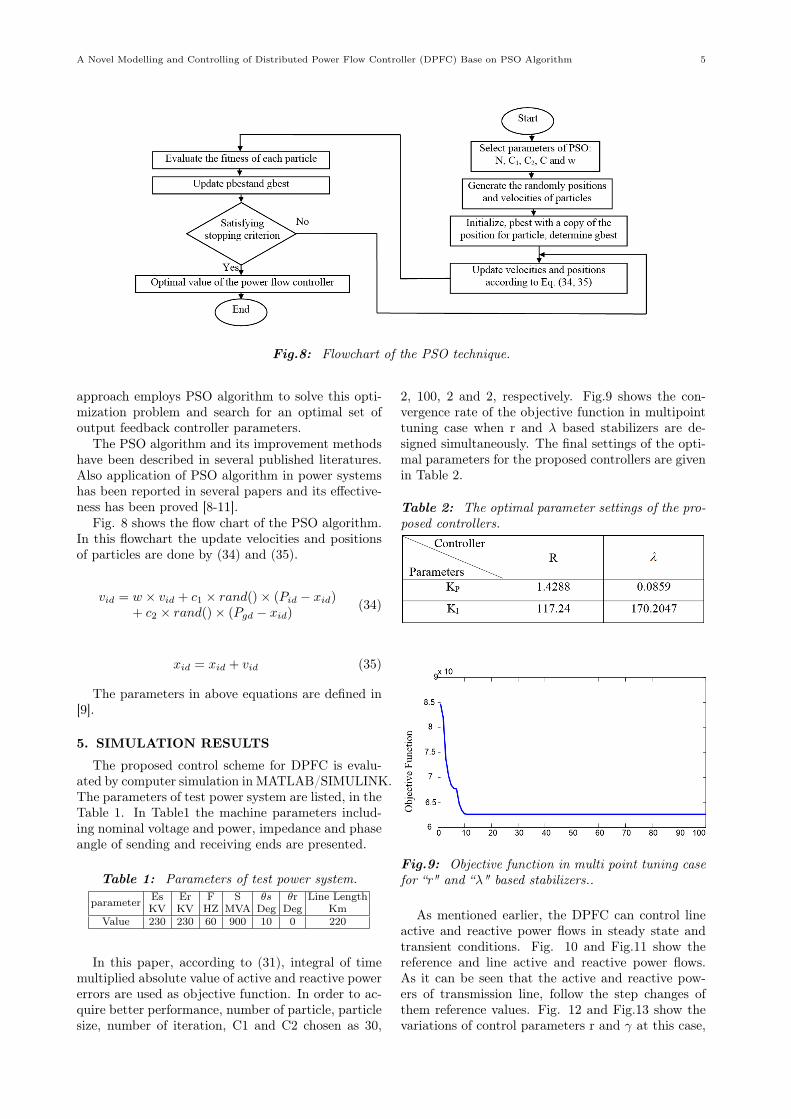
Fig.8: Flowchart of the PSO technique.
approach employs PSO algorithm to solve this opti-mization problem and search for an optimal set ofoutput feedback controller parameters.
The PSO algorithm and its improvement methodshave been described in several published literatures.Also application of PSO algorithm in power systemshas been reported in several papers and its effective-ness has been proved [8-11].
Fig. 8 shows the flow chart of the PSO algorithm.In this flowchart the update velocities and positionsof particles are done by (34) and (35).
vid = w × vid + c1 × rand()× (Pid − xid)+ c2 × rand()× (Pgd − xid)
(34)
xid = xid + vid (35)
The parameters in above equations are defined in[9].
5. SIMULATION RESULTS
The proposed control scheme for DPFC is evalu-ated by computer simulation in MATLAB/SIMULINK.The parameters of test power system are listed, in theTable 1. In Table1 the machine parameters includ-ing nominal voltage and power, impedance and phaseangle of sending and receiving ends are presented.
Table 1: Parameters of test power system.
parameter Es Er F S θs θr Line LengthKV KV HZ MVA Deg Deg Km
Value 230 230 60 900 10 0 220
In this paper, according to (31), integral of timemultiplied absolute value of active and reactive powererrors are used as objective function. In order to ac-quire better performance, number of particle, particlesize, number of iteration, C1 and C2 chosen as 30,
2, 100, 2 and 2, respectively. Fig.9 shows the con-vergence rate of the objective function in multipointtuning case when r and λ based stabilizers are de-signed simultaneously. The final settings of the opti-mal parameters for the proposed controllers are givenin Table 2.
Table 2: The optimal parameter settings of the pro-posed controllers.
Fig.9: Objective function in multi point tuning casefor “r" and “λ" based stabilizers..
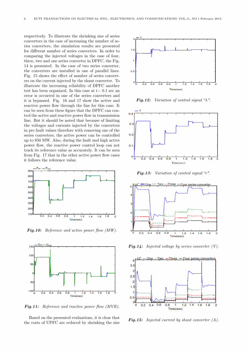
As mentioned earlier, the DPFC can control lineactive and reactive power flows in steady state andtransient conditions. Fig. 10 and Fig.11 show thereference and line active and reactive power flows.As it can be seen that the active and reactive pow-ers of transmission line, follow the step changes ofthem reference values. Fig. 12 and Fig.13 show thevariations of control parameters r and γ at this case,
6 ECTI TRANSACTIONS ON ELECTRICAL ENG., ELECTRONICS, AND COMMUNICATIONS VOL.11, NO.1 February 2013
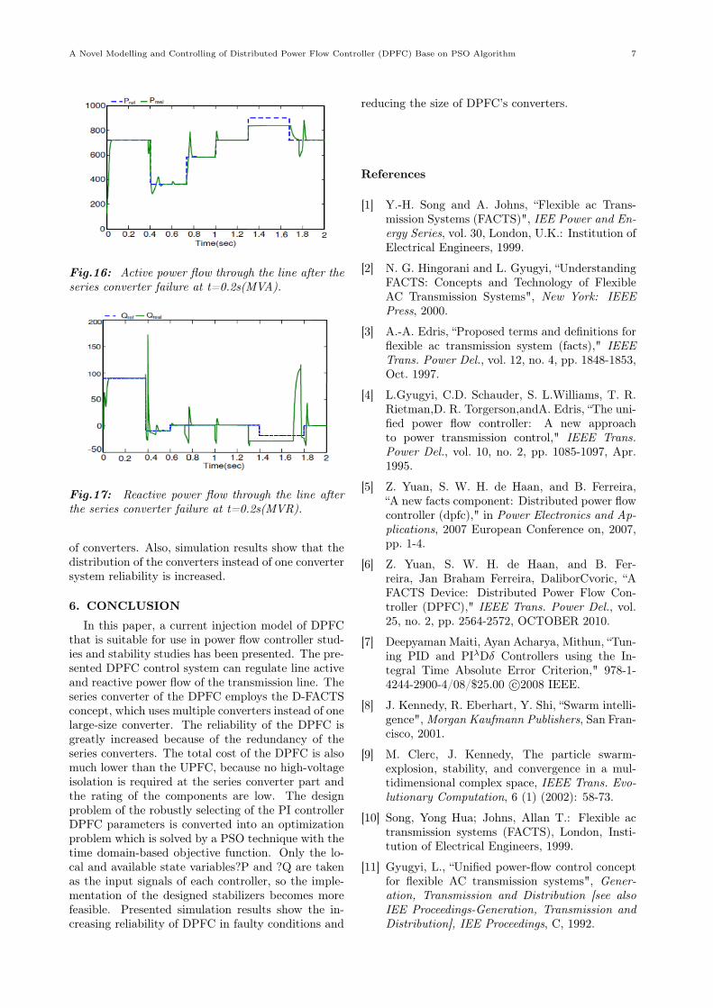
respectively. To illustrate the shrinking size of seriesconverters in the case of increasing the number of se-ries converters, the simulation results are presentedfor different number of series converters. In order tocomparing the injected voltages in the case of four,three, two and one series converter in DPFC, the Fig.14 is presented. In the case of two series converter,the converters are installed in one of parallel lines.Fig. 15 shows the effect of number of series convert-ers on the current injected by the shunt converter. Toillustrate the increasing reliability of DPFC anothertest has been organized. In this case at t= 0.1 sec anerror is occurred in one of the series converters andit is bypassed. Fig. 16 and 17 show the active andreactive power flow through the line for this case. Itcan be seen from these figure that the DPFC can con-trol the active and reactive power flow in transmissionline. But it should be noted that because of limitingthe voltages and currents injected by the convertersin pre fault values therefore with removing one of theseries converters, the active power can be controlledup to 850 MW. Also, during the fault and high activepower flow, the reactive power control loop can nottrack its reference value as accurately. It can be seenfrom Fig. 17 that in the other active power flow casesit follows the reference value.
Fig.10: Reference and active power flow (MW).
Fig.11: Reference and reactive power flow (MVR).
Based on the presented evaluations, it is clear thatthe costs of UPFC are reduced by shrinking the size
Fig.12: Variation of control signal “λ".
Fig.13: Variation of control signal “r".
Fig.14: Injected voltage by series converter (V).
Fig.15: Injected current by shunt converter (A).
A Novel Modelling and Controlling of Distributed Power Flow Controller (DPFC) Base on PSO Algorithm 7
Fig.16: Active power flow through the line after theseries converter failure at t=0.2s(MVA).
Fig.17: Reactive power flow through the line afterthe series converter failure at t=0.2s(MVR).
of converters. Also, simulation results show that thedistribution of the converters instead of one convertersystem reliability is increased.
6. CONCLUSION
In this paper, a current injection model of DPFCthat is suitable for use in power flow controller stud-ies and stability studies has been presented. The pre-sented DPFC control system can regulate line activeand reactive power flow of the transmission line. Theseries converter of the DPFC employs the D-FACTSconcept, which uses multiple converters instead of onelarge-size converter. The reliability of the DPFC isgreatly increased because of the redundancy of theseries converters. The total cost of the DPFC is alsomuch lower than the UPFC, because no high-voltageisolation is required at the series converter part andthe rating of the components are low. The designproblem of the robustly selecting of the PI controllerDPFC parameters is converted into an optimizationproblem which is solved by a PSO technique with thetime domain-based objective function. Only the lo-cal and available state variables?P and ?Q are takenas the input signals of each controller, so the imple-mentation of the designed stabilizers becomes morefeasible. Presented simulation results show the in-creasing reliability of DPFC in faulty conditions and
reducing the size of DPFC’s converters.
References
[1] Y.-H. Song and A. Johns, “Flexible ac Trans-mission Systems (FACTS)", IEE Power and En-ergy Series, vol. 30, London, U.K.: Institution ofElectrical Engineers, 1999.
[2] N. G. Hingorani and L. Gyugyi, “UnderstandingFACTS: Concepts and Technology of FlexibleAC Transmission Systems", New York: IEEEPress, 2000.
[3] A.-A. Edris, “Proposed terms and definitions forflexible ac transmission system (facts)," IEEETrans. Power Del., vol. 12, no. 4, pp. 1848-1853,Oct. 1997.
[4] L.Gyugyi, C.D. Schauder, S. L.Williams, T. R.Rietman,D. R. Torgerson,andA. Edris, “The uni-fied power flow controller: A new approachto power transmission control," IEEE Trans.Power Del., vol. 10, no. 2, pp. 1085-1097, Apr.1995.
[5] Z. Yuan, S. W. H. de Haan, and B. Ferreira,“A new facts component: Distributed power flowcontroller (dpfc)," in Power Electronics and Ap-plications, 2007 European Conference on, 2007,pp. 1-4.
[6] Z. Yuan, S. W. H. de Haan, and B. Fer-reira, Jan Braham Ferreira, DaliborCvoric, “AFACTS Device: Distributed Power Flow Con-troller (DPFC)," IEEE Trans. Power Del., vol.25, no. 2, pp. 2564-2572, OCTOBER 2010.
[7] Deepyaman Maiti, Ayan Acharya, Mithun, “Tun-ing PID and PIλDδ Controllers using the In-tegral Time Absolute Error Criterion," 978-1-4244-2900-4/08/$25.00 c⃝2008 IEEE.
[8] J. Kennedy, R. Eberhart, Y. Shi, “Swarm intelli-gence", Morgan Kaufmann Publishers, San Fran-cisco, 2001.
[9] M. Clerc, J. Kennedy, The particle swarm-explosion, stability, and convergence in a mul-tidimensional complex space, IEEE Trans. Evo-lutionary Computation, 6 (1) (2002): 58-73.
[10] Song, Yong Hua; Johns, Allan T.: Flexible actransmission systems (FACTS), London, Insti-tution of Electrical Engineers, 1999.
[11] Gyugyi, L., “Unified power-flow control conceptfor flexible AC transmission systems", Gener-ation, Transmission and Distribution [see alsoIEE Proceedings-Generation, Transmission andDistribution], IEE Proceedings, C, 1992.

8 ECTI TRANSACTIONS ON ELECTRICAL ENG., ELECTRONICS, AND COMMUNICATIONS VOL.11, NO.1 February 2013
Ali Ajami received his B.Sc. and M.Sc. degrees from the Electrical andComputer Engineering Faculty of TabrizUniversity, Iran, in Electronic Engineer-ing and Power Engineering in 1996 and1999, respectively, and his Ph.D. degreein 2005 from the Electrical and Com-puter Engineering Faculty of Tabriz Uni-versity, Iran, in Power Engineering. Hismain research interests are dynamic andsteady state modelling and analysis of
FACTS devices, harmonics and power quality compensationsystems, microprocessors, DSP and computer based controlsystems.
Behrouz soulat was born in Tabriz,Iran on 1988. He obtained his B.Sc. de-gree (2010), and MSC (2012) in electri-cal power engineering from the IslamicAzad University of Ahar, Iran. He isa member of Young Researchers Club,Islamic Azad University, Ahar branch,Ahar, Iran from 2012. His major fieldsof interest include power system stabil-ity, FACTs device to Power System Con-trol Design.
Amin Safari received the B.Sc. andM.Sc. degrees in Electrical Engineer-ing in 2007 and 2009, respectively. Cur-rently, he is a Ph.D. student of PowerElectrical Engineering, Iran Universityof Science and Technology, Tehran, Iran.His areas of interest in research areApplication of artificial intelligence topower system control design, FACTS de-vice and fuzzy sets and systems. He haspublished more than 60 papers in inter-
national journals and conference proceedings.