Embed Size (px)
Citation preview
SMC guide to ATEX compliant products
SMC guide to ATEX compliant products
CAT.DKI-50185- A
Continuously or for long periods>1000 hours/year
Occasionally10~1000 hours/year
Presence of the explosiveatmosphere
1
2
3 Rarely or for short periods<10 hours/year
0
1
2
Equipmentcategory
SMC - provide products SMC - provide products
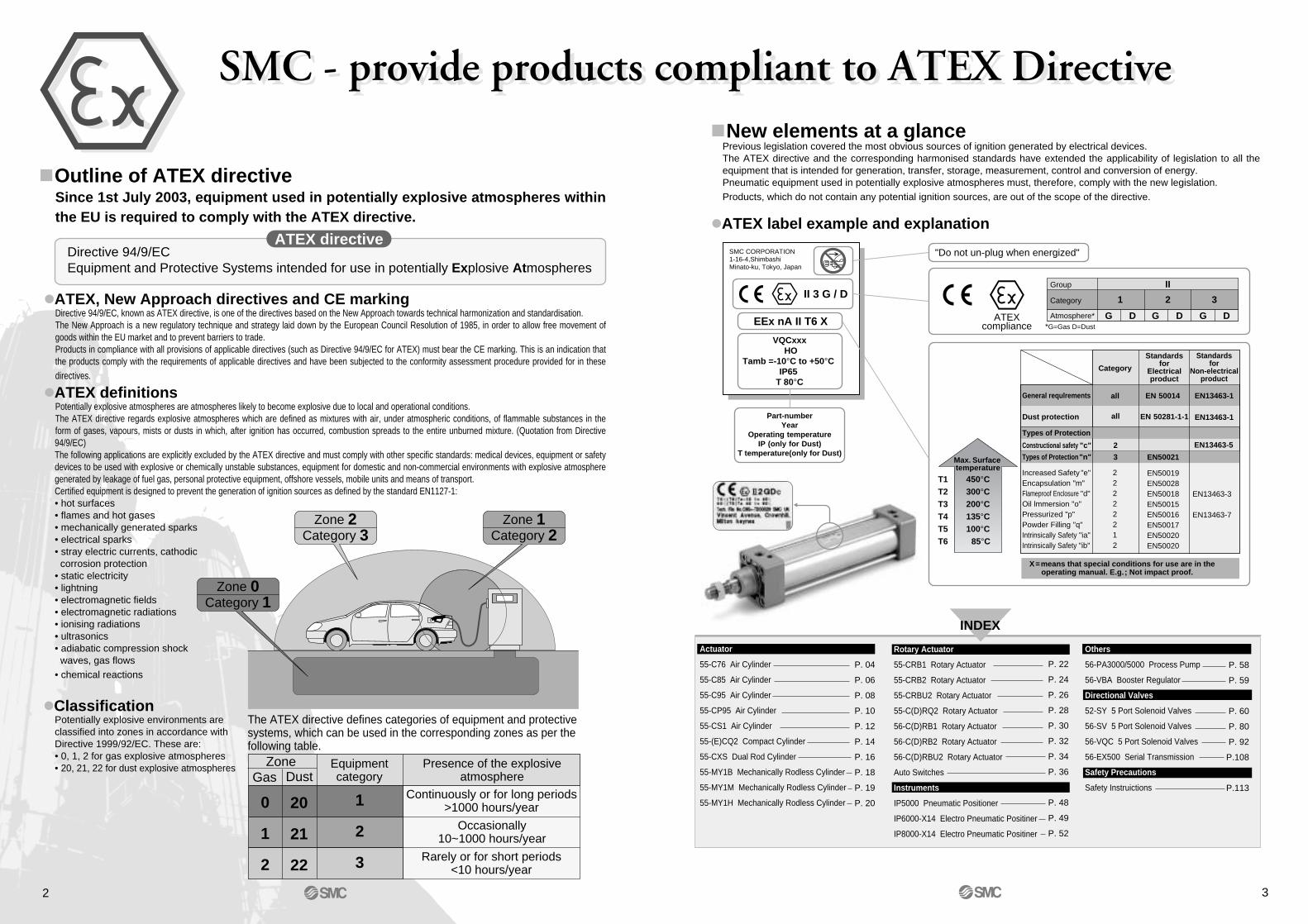
Outline of ATEX directiveSince 1st July 2003, equipment used in potentially explosive atmospheres within the EU is required to comply with the ATEX directive.
ATEX, New Approach directives and CE markingDirective 94/9/EC, known as ATEX directive, is one of the directives based on the New Approach towards technical harmonization and standardisation.The New Approach is a new regulatory technique and strategy laid down by the European Council Resolution of 1985, in order to allow free movement of goods within the EU market and to prevent barriers to trade.Products in compliance with all provisions of applicable directives (such as Directive 94/9/EC for ATEX) must bear the CE marking. This is an indication that the products comply with the requirements of applicable directives and have been subjected to the conformity assessment procedure provided for in these directives.
ATEX definitionsPotentially explosive atmospheres are atmospheres likely to become explosive due to local and operational conditions.The ATEX directive regards explosive atmospheres which are defined as mixtures with air, under atmospheric conditions, of flammable substances in the form of gases, vapours, mists or dusts in which, after ignition has occurred, combustion spreads to the entire unburned mixture. (Quotation from Directive 94/9/EC)The following applications are explicitly excluded by the ATEX directive and must comply with other specific standards: medical devices, equipment or safety devices to be used with explosive or chemically unstable substances, equipment for domestic and non-commercial environments with explosive atmosphere generated by leakage of fuel gas, personal protective equipment, offshore vessels, mobile units and means of transport.Certified equipment is designed to prevent the generation of ignition sources as defined by the standard EN1127-1:• hot surfaces• flames and hot gases• mechanically generated sparks• electrical sparks• stray electric currents, cathodic corrosion protection• static electricity• lightning• electromagnetic fields• electromagnetic radiations• ionising radiations• ultrasonics• adiabatic compression shock waves, gas flows• chemical reactions
ClassificationPotentially explosive environments are classified into zones in accordance with Directive 1999/92/EC. These are:• 0, 1, 2 for gas explosive atmospheres• 20, 21, 22 for dust explosive atmospheres
Directive 94/9/ECEquipment and Protective Systems intended for use in potentially Explosive Atmospheres
ATEX directive
Zone 0Category 1
Zone 2Category 3
Zone 1Category 2
The ATEX directive defines categories of equipment and protective systems, which can be used in the corresponding zones as per the following table.
ZoneGas Dust
20
21
22
2
New elements at a glancePrevious legislation covered the most obvious sources of ignition generated by electrical devices.The ATEX directive and the corresponding harmonised standards have extended the applicability of legislation to all the equipment that is intended for generation, transfer, storage, measurement, control and conversion of energy.Pneumatic equipment used in potentially explosive atmospheres must, therefore, comply with the new legislation.Products, which do not contain any potential ignition sources, are out of the scope of the directive.
ATEX label example and explanation
Part-numberYear
Operating temperatureIP (only for Dust)
T temperature(only for Dust)
ATEXcompliance
"Do not un-plug when energized"
II 3 G / D
EEx nA II T6 X
VQCxxx HO
Tamb =-10°C to +50°C IP65
T 80°C
SMC CORPORATION1-16-4,Shimbashi Minato-ku, Tokyo, Japan
Group
Atmosphere* G G DD G D*G=Gas D=Dust
II
3Category 1 2
T1T2T3T4T5T6
450°C300°C200°C135°C100°C 85°C
Max. Surface temperature
Category
Standardsfor
Electricalproduct
Standardsfor
Non-electricalproduct
General requlrements all EN 50014 EN13463-1
EN13463-1Dust protection all EN 50281-1-1
Types of Protection
Constructional safety "c" 2 EN13463-5
Types of Protection "n" 3 EN50021
Increased Safety "e"Encapsulation "m"Flameproof Enclosure "d"Oil lmmersion "o"Pressurized "p"Powder Filling "q"Intrinsically Safety "ia"Intrinsically Safety "ib"
22222212
EN50019EN50028EN50018EN50015EN50016EN50017EN50020EN50020
EN13463-3
EN13463-7
X=means that special conditions for use are in the operating manual. E.g.; Not impact proof.
compliant to ATEX Directivecompliant to ATEX Directive
INDEX
P. 04
P. 06
P. 08
P. 10
P. 12
P. 14
P. 16
P. 18
P. 19
P. 20
P. 22
P. 24
P. 26
P. 28
P. 30
P. 32
P. 34
P. 36
P. 48
P. 49
P. 52
P. 58
P. 59
P. 60
P. 80
P. 92
P.108
P.113
Rotary Actuator
55-CRB1 Rotary Actuator
55-CRB2 Rotary Actuator
55-CRBU2 Rotary Actuator
55-C(D)RQ2 Rotary Actuator
56-C(D)RB1 Rotary Actuator
56-C(D)RB2 Rotary Actuator
56-C(D)RBU2 Rotary Actuator
Auto Switches
Instruments
IP5000 Pneumatic Positioner
IP6000-X14 Electro Pneumatic Positiner
IP8000-X14 Electro Pneumatic Positiner
Actuator
55-C76 Air Cylinder
55-C85 Air Cylinder
55-C95 Air Cylinder
55-CP95 Air Cylinder
55-CS1 Air Cylinder
55-(E)CQ2 Compact Cylinder
55-CXS Dual Rod Cylinder
55-MY1B Mechanically Rodless Cylinder
55-MY1M Mechanically Rodless Cylinder
55-MY1H Mechanically Rodless Cylinder
Others
56-PA3000/5000 Process Pump
56-VBA Booster Regulator
Directional Valves
52-SY 5 Port Solenoid Valves
56-SV 5 Port Solenoid Valves
56-VQC 5 Port Solenoid Valves
56-EX500 Serial Transmission
Safety Precautions
Safety Instruictions
3
TypeModel No. Wiring
(Output)
Load voltage
Indi
cato
r
Electrical entry ApplicableloadDC AC
Lead wire∗ (m)
0.5(—)
3(L)
5(Z)
Reedauto switch
Solid stateauto switch
Rail mounting
D-A73-588
D-A80-588
D-A73H-588
D-A80H-588
D-F7PV-588
D-F7P-588
Band mounting
D-C73-588
D-C80-588
D-H7A2-588
Grommet(Perpendicular entry)
Grommet(In-line entry)
Grommet(Perpendicular entry)
Grommet(In-line entry)
Yes
No
Yes
No
Yes
2-wiring
3-wiring(PNP)
24V
24V or less
24V
24V or less
24V
12V
48V
12V
48V
5V, 12V
48V or less
48V or less
IC circuit
IC circuit
IC circuit
RelayPLC
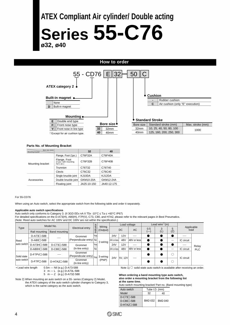
For 55-CD76
When using an Auto switch, select the appropriate switch from the following table and order it separately.
Applicable auto switch specificationsAuto switch only conforms to Category 3. (II 3GD EEx nA II T5x -10°C ≤ Ta ≤ +60°C IP67)For detailed specifications on the D-A73(H), A80(H), F7P(V), C73, C80, and H7A2, please refer to the relevant pages in Best Pneumatics.(Note: Reed auto switches for AC 100V and DC 100V are not within the specification.)
Note 1) solid state auto switch is available after receiving an order.• Lead wire length 0.5m --- Nil (e.g.) D-A73-5883 m --- L (e.g.) D-A73L-5885 m --- Z (e.g.) D-A73Z-588
Note 2) When mounting an auto switch on a 55- series (Category 2) Model, the ATEX category of the auto switch cylinder changes to Category 3, which is the same category as the auto switch.
When ordering a band mounting type auto switch,also order a mounting bracket from the following listat the same time.Auto switch mounting bracket/ Part no. (Band mounting type)
Auto switchModelD-C73-588D-C80-588D-H7A2-588
Tube I.D. (mm)32 40
BM2-032 BM2-040
4
How to order
ATEX Compliant Air cylinder/ Double acting
Series 55-C76 ø32, ø40
55 - CD76
Built-in magnet
Bore sizeStandard Stroke
-C
Rubber cushion Air cushion (only "E" execution)
Cushion
3240
32mm40mm
MountingEF∗Y∗
Double end typeFront nose typeFront nose in line type
50 CE 32
ATEX category 2
DNoneBuilt-in magnet
∗ Except for air cushion type.
Bore size32mm40mm
Standard stroke (mm) 10, 25, 40, 50, 80, 100125, 160, 200, 250, 300
Max. stroke (mm)
1000
Mounting bracketBore size (mm)
Parts No. of Mounting Bracket
Mounting bracketC76F32B C76F40B
Flange, Foot(2 pcs. with mountingnut 1 pc.)
32 40
Flange, Foot (1pc.) C76F32A C76F40A
Trunnion C76T32 C76T40
Clevis C76C32 C76C40
Single knuckle joint KJ10DA KJ12DA
Accessories Double knuckle joint GKM10-20A GKM12-24A
Floating joint JA25-10-150 JA40-12-175
5
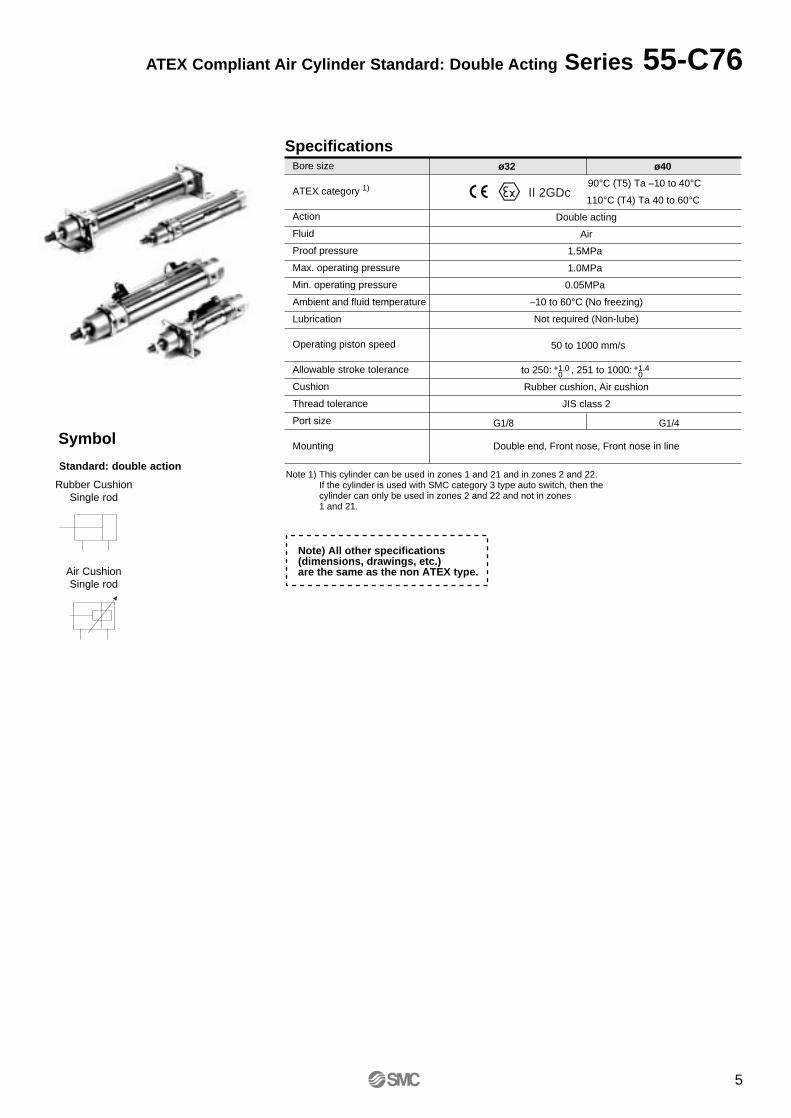
ATEX Compliant Air Cylinder Standard: Double Acting Series 55-C76
Symbol
Rubber CushionSingle rod
Standard: double action
Air CushionSingle rod
SpecificationsBore size
ATEX category 1)
Action
Fluid
Proof pressure
Max. operating pressure
Min. operating pressure
Ambient and fluid temperature
Lubrication
Operating piston speed
Allowable stroke tolerance
Cushion
Thread tolerance
Port size
Mounting
90°C (T5) Ta –10 to 40°C
110°C (T4) Ta 40 to 60°C
Double acting
Air
1.5MPa
1.0MPa
0.05MPa
–10 to 60°C (No freezing)
Not required (Non-lube)
to 250: , 251 to 1000:
Rubber cushion, Air cushion
JIS class 2
Double end, Front nose, Front nose in line
ø32 ø40
+1.0 0
+1.4 0
G1/8 G1/4
II 2GDc
50 to 1000 mm/s
Note) All other specifications (dimensions, drawings, etc.) are the same as the non ATEX type.
Note 1) This cylinder can be used in zones 1 and 21 and in zones 2 and 22.If the cylinder is used with SMC category 3 type auto switch, then the cylinder can only be used in zones 2 and 22 and not in zones 1 and 21.
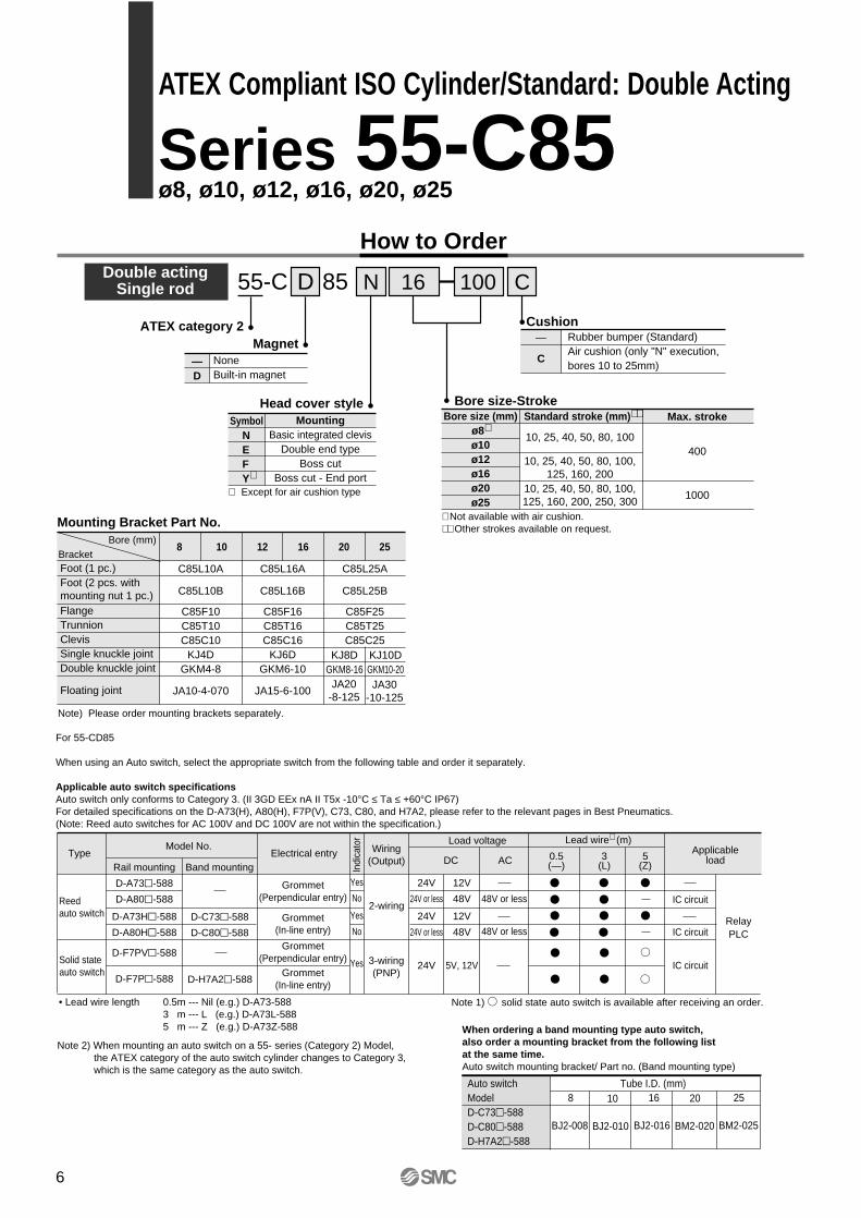
Double actingSingle rod D 8555-C N 16 C100
Magnet
Symbol
Head cover style Bore size-StrokeMounting
Basic integrated clevisDouble end type
Boss cutBoss cut - End port
—D
NoneBuilt-in magnet
—Cushion
Rubber bumper (Standard)Air cushion (only "N" execution,bores 10 to 25mm)
How to Order
NEFY∗
Standard stroke (mm)∗∗Bore size (mm)ø8∗ø10ø12ø16ø20ø25
∗ Except for air cushion type
Max. stroke
10, 25, 40, 50, 80, 100
10, 25, 40, 50, 80, 100,125, 160, 200
10, 25, 40, 50, 80, 100,125, 160, 200, 250, 300
400
1000
∗ Not available with air cushion.∗∗ Other strokes available on request.
C
BracketBore (mm)
Mounting Bracket Part No.
Foot (1 pc.)
Floating joint
Foot (2 pcs. withmounting nut 1 pc.)FlangeTrunnionClevisSingle knuckle jointDouble knuckle joint
8 10 12 16 20 25
C85L10A
C85L10B
JA10-4-070
C85F10C85T10C85C10
KJ4DGKM4-8
C85L16A C85L25A
C85L16B C85L25B
C85F25C85T25C85C25
JA15-6-100
C85F16C85T16C85C16
KJ6DGKM6-10
KJ8DGKM8-16
KJ10DGKM10-20JA30
-10-125JA20
-8-125
Note) Please order mounting brackets separately.
ATEX category 2
TypeModel No. Wiring
(Output)
Load voltage
Indi
cato
r
Electrical entry ApplicableloadDC AC
Lead wire∗ (m)
0.5(—)
3(L)
5(Z)
Reedauto switch
Solid stateauto switch
Rail mounting
D-A73-588
D-A80-588
D-A73H-588
D-A80H-588
D-F7PV-588
D-F7P-588
Band mounting
D-C73-588
D-C80-588
D-H7A2-588
Grommet(Perpendicular entry)
Grommet(In-line entry)
Grommet(Perpendicular entry)
Grommet(In-line entry)
Yes
No
Yes
No
Yes
2-wiring
3-wiring(PNP)
24V
24V or less
24V
24V or less
24V
12V
48V
12V
48V
5V, 12V
48V or less
48V or less
IC circuit
IC circuit
IC circuit
RelayPLC
For 55-CD85
When using an Auto switch, select the appropriate switch from the following table and order it separately.
Applicable auto switch specificationsAuto switch only conforms to Category 3. (II 3GD EEx nA II T5x -10°C ≤ Ta ≤ +60°C IP67)For detailed specifications on the D-A73(H), A80(H), F7P(V), C73, C80, and H7A2, please refer to the relevant pages in Best Pneumatics.(Note: Reed auto switches for AC 100V and DC 100V are not within the specification.)
Note 1) solid state auto switch is available after receiving an order.• Lead wire length 0.5m --- Nil (e.g.) D-A73-5883 m --- L (e.g.) D-A73L-5885 m --- Z (e.g.) D-A73Z-588
Note 2) When mounting an auto switch on a 55- series (Category 2) Model, the ATEX category of the auto switch cylinder changes to Category 3, which is the same category as the auto switch.
When ordering a band mounting type auto switch,also order a mounting bracket from the following listat the same time.Auto switch mounting bracket/ Part no. (Band mounting type)
Auto switchModelD-C73-588D-C80-588D-H7A2-588
Tube I.D. (mm)8 10
BJ2-008 BJ2-010
16
BJ2-016
20
BM2-020
25
BM2-025
6
ATEX Compliant ISO Cylinder/Standard: Double Acting
Series 55-C85 ø8, ø10, ø12, ø16, ø20, ø25
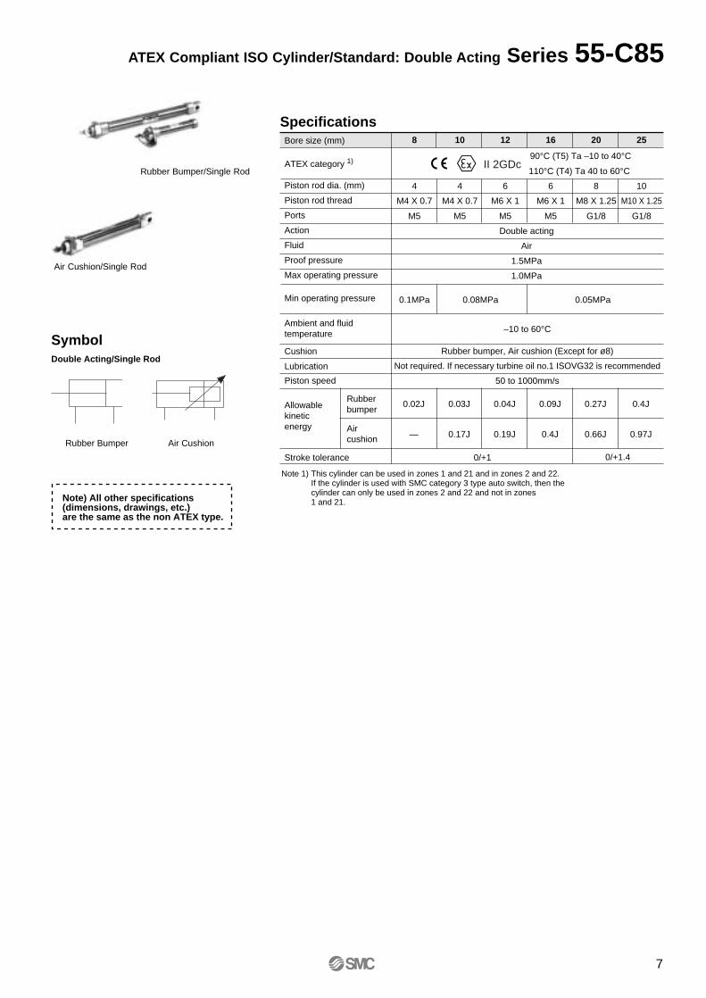
SpecificationsBore size (mm)
Piston rod dia. (mm)
Piston rod thread
Ports
Action
Fluid
Proof pressure
Max operating pressure
8 10 12 16 20 25
M4 X 0.7 M4 X 0.7 M6 X 1 M6 X 1 M8 X 1.25 M10 X 1.25
4 4 6 6 8 10
M5 M5 M5 M5 G1/8 G1/8
Double acting
Air
1.5MPa
1.0MPa
0.1MPa 0.08MPa
–10 to 60°C
50 to 1000mm/s
0.02J 0.03J 0.04J 0.09J 0.27J 0.4J
— 0.17J 0.19J 0.4J
0/+1
0.66J 0.97J
0/+1.4
Not required. If necessary turbine oil no.1 ISOVG32 is recommended
Rubber bumper, Air cushion (Except for ø8)
0.05MPaMin operating pressure
Cushion
Lubrication
Ambient and fluid temperature
Piston speed
Stroke tolerance
Allowablekineticenergy
Rubberbumper
Aircushion
SymbolDouble Acting/Single Rod
Rubber Bumper Air Cushion
90°C (T5) Ta –10 to 40°C
110°C (T4) Ta 40 to 60°CII 2GDcATEX category 1)
Note) All other specifications (dimensions, drawings, etc.) are the same as the non ATEX type.
Note 1) This cylinder can be used in zones 1 and 21 and in zones 2 and 22.If the cylinder is used with SMC category 3 type auto switch, then the cylinder can only be used in zones 2 and 22 and not in zones 1 and 21.
7
ATEX Compliant ISO Cylinder/Standard: Double Acting Series 55-C85
Rubber Bumper/Single Rod
Air Cushion/Single Rod
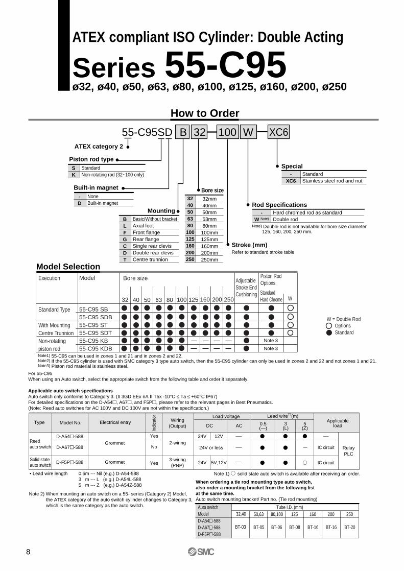
55-C95SD
How to Order
Built-in magnet Bore size
Stroke (mm)Refer to standard stroke table
-W Note)
Hard chromed rod as standard Double rod
Rod Specifications3240506380100125160200250
32mm40mm50mm63mm80mm100mm125mm160mm200mm250mm
MountingBLFGCDT
Basic/Without bracketAxial footFront flangeRear flangeSingle rear clevisDouble rear clevisCentre trunnion
100 WB 32ATEX category 2
-D
NoneBuilt-in magnet
Execution
Standard Type
With MountingCentre TrunnionNon-rotatingpiston rod
Model
55-C95 SB55-C95 SDB55-C95 ST55-C95 SDT55-C95 KB55-C95 KDB
AdjustableStroke EndCushioning
Piston RodOptions
StandardHard Chrome W
OptionsStandard
Model Selection
Note) Double rod is not available for bore size diameter 125, 160, 200, 250 mm.
Note1) 55-C95 can be used in zones 1 and 21 and in zones 2 and 22.Note2) If the 55-C95 cylinder is used with SMC category 3 type auto switch, then the 55-C95 cylinder can only be used in zones 2 and 22 and not zones 1 and 21.Note3) Piston rod material is stainless steel.
Bore size
32 40 50 63 80 100 125 160 200 250
Type Model No. Wiring(Output)
Load voltage
Indi
cato
r
Electrical entry ApplicableloadDC AC
Lead wire∗ (m)
0.5(—)
3(L)
5(Z)
Reedauto switch
Solid stateauto switch
D-A54-588
D-A67-588
D-F5P-588
Grommet
Grommet
Yes
No
Yes
2-wiring
3-wiring(PNP)
24V 12V
IC circuit
IC circuit
RelayPLC
For 55-C95When using an Auto switch, select the appropriate switch from the following table and order it separately.
Applicable auto switch specificationsAuto switch only conforms to Category 3. (II 3GD EEx nA II T5x -10°C ≤ Ta ≤ +60°C IP67)For detailed specifications on the D-A54, A67, and F5P, please refer to the relevant pages in Best Pneumatics.(Note: Reed auto switches for AC 100V and DC 100V are not within the specification.)
Note 1) solid state auto switch is available after receiving an order.• Lead wire length 0.5m --- Nil (e.g.) D-A54-5883 m --- L (e.g.) D-A54L-5885 m --- Z (e.g.) D-A54Z-588
Note 2) When mounting an auto switch on a 55- series (Category 2) Model, the ATEX category of the auto switch cylinder changes to Category 3, which is the same category as the auto switch.
When ordering a tie rod mounting type auto switch,also order a mounting bracket from the following listat the same time.Auto switch mounting bracket/ Part no. (Tie rod mounting)
Auto switchModelD-A54-588D-A67-588D-F5P-588
Tube I.D. (mm)32,40 50,63
BT-03 BT-05
24V or less
24V 5V,12V
80,100
BT-06
125
BT-08
160
BT-16
200
BT-16
250
BT-20
Piston rod typeSK
StandardNon-rotating rod (32~100 only)
XC6
-XC6
Standard Stainless steel rod and nut
Special
Note 3
Note 3
W = Double Rod
8
ATEX compliant ISO Cylinder: Double Acting
Series 55-C95 ø32, ø40, ø50, ø63, ø80, ø100, ø125, ø160, ø200, ø250
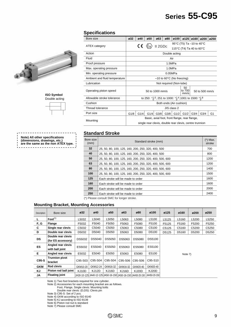
SpecificationsBore size
ATEX category
Action
Fluid
Proof pressure
Max. operating pressure
Min. operating pressure
Ambient and fluid temperature
Lubrication
Operating piston speed
Allowable stroke tolerance
Cushion
Thread tolerance
Port size
Mounting
95°C (T5) Ta –10 to 40°C
115°C (T4) Ta 40 to 60°C
Double acting
Air
1.5MPa
1.0MPa
0.05MPa
–10 to 60°C (No freezing)
Not required (Non-lube)
to 250: , 251 to 1000: ,1001 to 1500:
Both ends (Air cushion)
JIS class 2
Basic, axial foot, front flange, rear flange,
single rear clevis, double rear clevis, centre trunnion
ø32 ø40 ø63 ø100
+1.0 0
Standard Stroke
32
40
50
63
80
100
125
160
200
250
Bore size(mm)
25, 50, 80, 100, 125, 160, 200, 250, 320, 400, 500
25, 50, 80, 100, 125, 160, 200, 250, 320, 400, 500
25, 50, 80, 100, 125, 160, 200, 250, 320, 400, 500, 600
25, 50, 80, 100, 125, 160, 200, 250, 320, 400, 500, 600
25, 50, 80, 100, 125, 160, 200, 250, 320, 400, 500, 600
25, 50, 80, 100, 125, 160, 200, 250, 320, 400, 500, 600
Each stroke will be made to order
Each stroke will be made to order
Each stroke will be made to order
Each stroke will be made to order
Standard stroke (mm)
ø50 ø80
+1.4 0
+1.8 0
G1/8 G1/4 G1/4 G3/8 G3/8 G1/2
(*) Max.stroke
700
800
1200
1200
1400
1500
1600
1600
2000
2400
ISO SymbolDouble acting
Mounting Bracket, Mounting Accessories
Note 1) Two foot brackets required for one cylinder.Note 2) Accessories for each mounting bracket are as follows.
Foot, Flange, Single clevis: Mounting boltsDouble rear clevis: (D,DS): Clevis pin
Note 3) C95-S: Set of 2 pcs.Note 4) GKM according to ISO 8140Note 5) KJ according to ISO 8139Note 6) Piston rod nut is standardNote 7) Please consult SMC
Foot(1)
FlangeSingle rear clevisDouble rear clevisDouble rear clevis(for ES accessory)Angled rear cleviswith ball jointAngled rear clevisTrunnion pivot bracketRod clevisPiston rod ball jointFloating joint
Bore size ø32 ø40 ø50 ø63 ø80 ø100Description
II 2GDc
ø125 ø160 ø200 ø250
G1/2 G3/4 G3/4 G1
LF, GCD
DS
ES
E
C95-S
GKMKJJA
ø250ø125 ø160 ø200
L5100
F5100
C5100
D5100
DS5100
ES5100
E5100
C95-S10
GKM20-40
KJ20D
JAH50-20-150
L5080
F5080
C5080
D5080
DS5080
ES5080
E5080
C95-S06
GKM20-40
KJ20D
JAH50-20-150
L5063
F5063
C5063
D5063
DS5063
ES5063
E5063
C95-S06
GKM16-32
KJ16D
JA50-16-150
L5050
F5050
C5050
D5050
DS5050
ES5050
E5050
C95-S04
GKM16-32
KJ16D
JA50-16-150
L5040
F5040
C5040
D5040
DS5040
ES5040
E5040
C95-S04
GKM12-24
KJ12D
JA40-12-125
L5032
F5032
C5032
D5032
DS5032
ES5032
E5032
C95-S03
GKM10-20
KJ10D
JA30-10-125
Note) All other specifications (dimensions, drawings, etc.) are the same as the non ATEX type.
(*) Please consult SMC for longer stroke.
L5125
F5125
C5125
D5125
L5160
F5160
C5160
D5160
L5200
F5200
C5200
D5200
L5250
F5250
C5250
D5250
50 to 1000 mm/s 50 to 500 mm/s50
to 700 mm/s
Note 7)
9
Series 55-C95
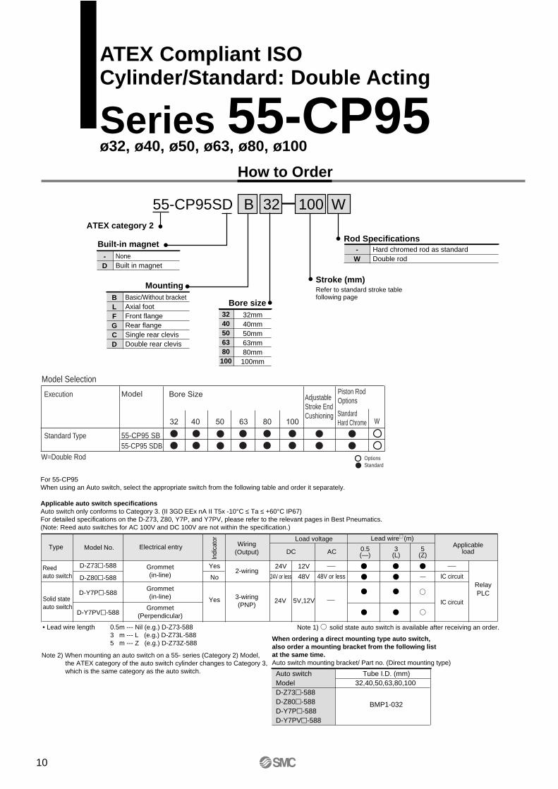
55-CP95SD
How to Order
Built-in magnet
Bore size
Stroke (mm)Refer to standard stroke table following page
-W
Hard chromed rod as standard Double rod
Rod Specifications
3240506380
100
32mm40mm50mm63mm80mm100mm
MountingBLFGCD
Basic/Without bracketAxial footFront flangeRear flangeSingle rear clevisDouble rear clevis
100 WB 32
Execution
Standard Type
Model
55-CP95 SB55-CP95 SDB
AdjustableStroke EndCushioning
Piston RodOptions
StandardHard Chrome W
OptionsStandard
Model Selection
W=Double Rod
ATEX category 2
-D
NoneBuilt in magnet
Type Model No. Wiring(Output)
Load voltage
Indi
cato
r
Electrical entry ApplicableloadDC AC
Lead wire∗ (m)
0.5(—)
3(L)
5(Z)
Reedauto switch
Solid stateauto switch
D-Z73-588
D-Z80-588
D-Y7P-588
D-Y7PV-588
Grommet(in-line)
Grommet(in-line)
Grommet(Perpendicular)
Yes
No
Yes
2-wiring
3-wiring(PNP)
24V
24V or less
12V
48V IC circuit
IC circuit
RelayPLC
For 55-CP95When using an Auto switch, select the appropriate switch from the following table and order it separately.
Applicable auto switch specificationsAuto switch only conforms to Category 3. (II 3GD EEx nA II T5x -10°C ≤ Ta ≤ +60°C IP67)For detailed specifications on the D-Z73, Z80, Y7P, and Y7PV, please refer to the relevant pages in Best Pneumatics.(Note: Reed auto switches for AC 100V and DC 100V are not within the specification.)
Note 1) solid state auto switch is available after receiving an order.• Lead wire length 0.5m --- Nil (e.g.) D-Z73-5883 m --- L (e.g.) D-Z73L-5885 m --- Z (e.g.) D-Z73Z-588
Note 2) When mounting an auto switch on a 55- series (Category 2) Model, the ATEX category of the auto switch cylinder changes to Category 3, which is the same category as the auto switch.
When ordering a direct mounting type auto switch,also order a mounting bracket from the following listat the same time.Auto switch mounting bracket/ Part no. (Direct mounting type)
Auto switchModelD-Z73-588D-Z80-588D-Y7P-588D-Y7PV-588
Tube I.D. (mm)32,40,50,63,80,100
BMP1-032
24V 5V,12V
48V or less
10
ATEX Compliant ISOCylinder/Standard: Double Acting
Series 55-CP95 ø32, ø40, ø50, ø63, ø80, ø100
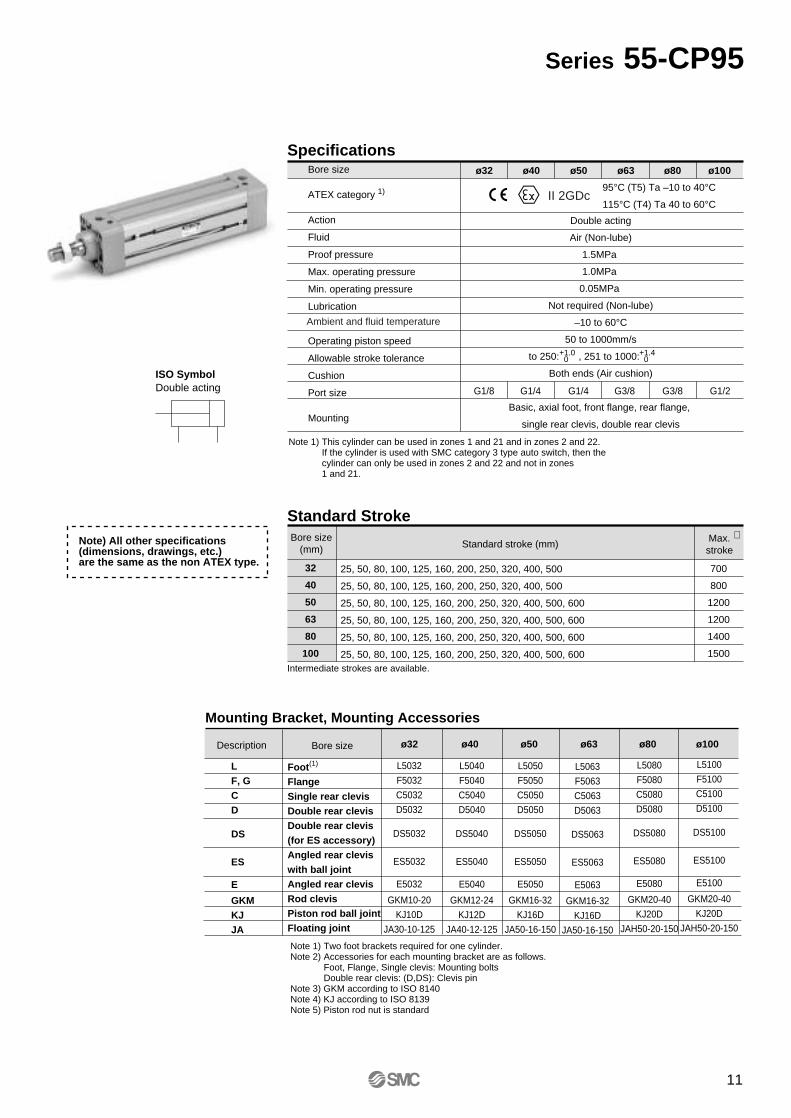
SpecificationsBore size
ATEX category 1)
Action
Fluid
Proof pressure
Max. operating pressure
Min. operating pressure
Lubrication
Operating piston speed
Allowable stroke tolerance
Cushion
Port size
Mounting
Double acting
Air (Non-lube)
1.5MPa
1.0MPa
0.05MPa
Not required (Non-lube)
–10 to 60°C
50 to 1000mm/s
to 250: , 251 to 1000:
Both ends (Air cushion)
Basic, axial foot, front flange, rear flange,
single rear clevis, double rear clevis
ø32 ø40 ø63 ø100
+1.0 0
Standard Stroke
32
40
50
63
80
100
Bore size(mm)
25, 50, 80, 100, 125, 160, 200, 250, 320, 400, 500
25, 50, 80, 100, 125, 160, 200, 250, 320, 400, 500
25, 50, 80, 100, 125, 160, 200, 250, 320, 400, 500, 600
25, 50, 80, 100, 125, 160, 200, 250, 320, 400, 500, 600
25, 50, 80, 100, 125, 160, 200, 250, 320, 400, 500, 600
25, 50, 80, 100, 125, 160, 200, 250, 320, 400, 500, 600
Standard stroke (mm)
ø50 ø80
+1.4 0
G1/8 G1/4 G1/4 G3/8 G3/8 G1/2
Max.stroke
700
800
1200
1200
1400
1500
Intermediate strokes are available.
ISO SymbolDouble acting
∗
Mounting Bracket, Mounting Accessories
Note 1) Two foot brackets required for one cylinder.Note 2) Accessories for each mounting bracket are as follows.
Foot, Flange, Single clevis: Mounting boltsDouble rear clevis: (D,DS): Clevis pin
Note 3) GKM according to ISO 8140Note 4) KJ according to ISO 8139Note 5) Piston rod nut is standard
Foot(1)
FlangeSingle rear clevisDouble rear clevisDouble rear clevis(for ES accessory)Angled rear cleviswith ball jointAngled rear clevisRod clevisPiston rod ball jointFloating joint
Bore size ø32 ø40 ø50 ø63 ø80 ø100Description
95°C (T5) Ta –10 to 40°C
115°C (T4) Ta 40 to 60°CII 2GDc
Note) All other specifications (dimensions, drawings, etc.) are the same as the non ATEX type.
Note 1) This cylinder can be used in zones 1 and 21 and in zones 2 and 22.If the cylinder is used with SMC category 3 type auto switch, then the cylinder can only be used in zones 2 and 22 and not in zones 1 and 21.
LF, GCD
DS
ES
E
GKMKJJA
L5032
F5032
C5032
D5032
DS5032
ES5032
E5032
GKM10-20
KJ10D
JA30-10-125
L5040
F5040
C5040
D5040
DS5040
ES5040
E5040
GKM12-24
KJ12D
JA40-12-125
L5050
F5050
C5050
D5050
DS5050
ES5050
E5050
GKM16-32
KJ16D
JA50-16-150
L5063
F5063
C5063
D5063
DS5063
ES5063
E5063
GKM16-32
KJ16D
JA50-16-150
L5080
F5080
C5080
D5080
DS5080
ES5080
E5080
GKM20-40
KJ20D
JAH50-20-150
L5100
F5100
C5100
D5100
DS5100
ES5100
E5100
GKM20-40
KJ20D
JAH50-20-150
Ambient and fluid temperature
11
Series 55-CP95
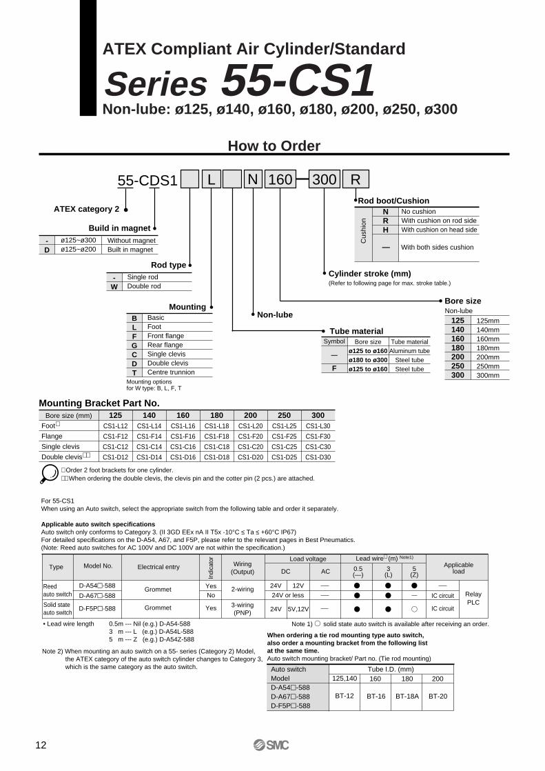
55-CDS1 L 300160
Bore size
125140160180200250300
125mm140mm160mm180mm200mm250mm300mm
MountingBLFGCDT
BasicFootFront flangeRear flangeSingle clevisDouble clevisCentre trunnion
Cylinder stroke (mm)(Refer to following page for max. stroke table.)
R
No cushionWith cushion on rod sideWith cushion on head side
Rod boot/Cushion
Cus
hion
NRH
Tube materialSymbol
—
F
Bore sizeø125 to ø160ø180 to ø300ø125 to ø160
Tube materialAluminum tube
Steel tubeSteel tube
Non-lube
Mounting Bracket Part No.Bore size (mm) 125
CS1-L12
CS1-F12
CS1-C12
CS1-D12
140CS1-L14
CS1-F14
CS1-C14
CS1-D14
160CS1-L16
CS1-F16
CS1-C16
CS1-D16
180CS1-L18
CS1-F18
CS1-C18
CS1-D18
200CS1-L20
CS1-F20
CS1-C20
CS1-D20
250CS1-L25
CS1-F25
CS1-C25
CS1-D25
300CS1-L30
CS1-F30
CS1-C30
CS1-D30
With both sides cushion
∗ Order 2 foot brackets for one cylinder.∗∗ When ordering the double clevis, the clevis pin and the cotter pin (2 pcs.) are attached.
Series 55-CS1ATEX Compliant Air Cylinder/Standard
Non-lube: ø125, ø140, ø160, ø180, ø200, ø250, ø300
How to Order
—
Foot∗
Flange
Single clevis
Double clevis∗∗
N
Rod type
-W
Single rodDouble rod
Build in magnet
-D
ø125~ø300ø125~ø200
Without magnetBuilt in magnet
ATEX category 2
Non-lube
Mounting optionsfor W type: B, L, F, T
Type Model No. Wiring(Output)
Load voltage
Indi
cato
r
Electrical entry ApplicableloadDC AC
Lead wire∗ (m) Note1)
0.5(—)
3(L)
5(Z)
Reedauto switch
Solid stateauto switch
D-A54-588
D-A67-588
D-F5P-588
Grommet
Grommet
YesNo
Yes
2-wiring
3-wiring(PNP)
24V 12V
IC circuit
IC circuit
RelayPLC
For 55-CS1When using an Auto switch, select the appropriate switch from the following table and order it separately.
Applicable auto switch specificationsAuto switch only conforms to Category 3. (II 3GD EEx nA II T5x -10°C ≤ Ta ≤ +60°C IP67)For detailed specifications on the D-A54, A67, and F5P, please refer to the relevant pages in Best Pneumatics.(Note: Reed auto switches for AC 100V and DC 100V are not within the specification.)
Note 1) solid state auto switch is available after receiving an order.• Lead wire length 0.5m --- Nil (e.g.) D-A54-5883 m --- L (e.g.) D-A54L-5885 m --- Z (e.g.) D-A54Z-588
Note 2) When mounting an auto switch on a 55- series (Category 2) Model, the ATEX category of the auto switch cylinder changes to Category 3, which is the same category as the auto switch.
When ordering a tie rod mounting type auto switch,also order a mounting bracket from the following listat the same time.Auto switch mounting bracket/ Part no. (Tie rod mounting)
Auto switchModelD-A54-588D-A67-588D-F5P-588
Tube I.D. (mm)125,140 160
BT-12 BT-16
24V or less
24V 5V,12V
180
BT-18A
200
BT-20
12
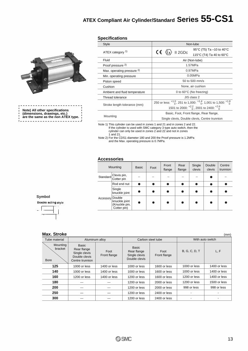
SpecificationsStyle
Fluid
Proof pressure 2)
Max. operating pressure 2)
Min. operating pressure
Piston speed
Cushion
Ambient and fluid temperature
Thread tolerance
Non-lube
Air (Non-lube)
Accessories
Mounting
Standard
Accessory
Clevis pin,Cotter pin
Basic FootFront flange
Rear flange
Singleclevis
Double clevis
Centre trunnion
Max. Stroke (mm)
Tube material Aluminum alloy Carbon steel tube
Mountingbracket
Bore
125
140
160
180
200
250
300
BasicRear flangeSingle clevisDouble clevis
Centre trunnion
1000 or less
1000 or less
1200 or less
—
—
—
—
1400 or less
1400 or less
1400 or less
—
—
—
—
1000 or less
1000 or less
1200 or less
1200 or less
1200 or less
1200 or less
1200 or less
1600 or less
1600 or less
1600 or less
2000 or less
2000 or less
2400 or less
2400 or less
FootFront flange
BasicRear flangeSingle clevisDouble clevis
FootFront flange
Stroke length tolerance (mm)
Mounting
0.05MPa
50 to 500 mm/s
None, air cushion
1.57MPa
0.97MPa
0 to 60°C (No freezing)
JIS class 2
250 or less: , 251 to 1,000: , 1,001 to 1,500:
1501 to 2000: , 2001 to 2400:
Basic, Foot, Front flange, Rear flange,
Single clevis, Double clevis, Centre trunnion
+1.4 0
+1.0 0
+1.8 0
+2.2 0
+2.6 0
— — — — — —
Doubleknuckle joint(Knuckle pin, Cotter pin)
Rod end nut
Single knuckle joint
ATEX category 1)95°C (T5) Ta –10 to 40°C
115°C (T4) Ta 40 to 60°CII 2GDc
Note 1) This cylinder can be used in zones 1 and 21 and in zones 2 and 22.If the cylinder is used with SMC category 3 type auto switch, then the cylinder can only be used in zones 2 and 22 and not in zones 1 and 21.
Note 2) For the CDS1 diameter 180 and 200 the Proof pressure is 1.2MPaand the Max. operating pressure is 0.7MPa.
Note) All other specifications (dimensions, drawings, etc.) are the same as the non ATEX type.
With auto switch
1000 or less
1000 or less
1200 or less
1200 or less
998 or less
-
-
1400 or less
1400 or less
1400 or less
1500 or less
998 or less
-
-
B, G, C, D, T L, F
Symbol
13
ATEX Compliant Air Cylinder/Standard Series 55-CS1
125140160180200
125mm140mm160mm180mm200mm
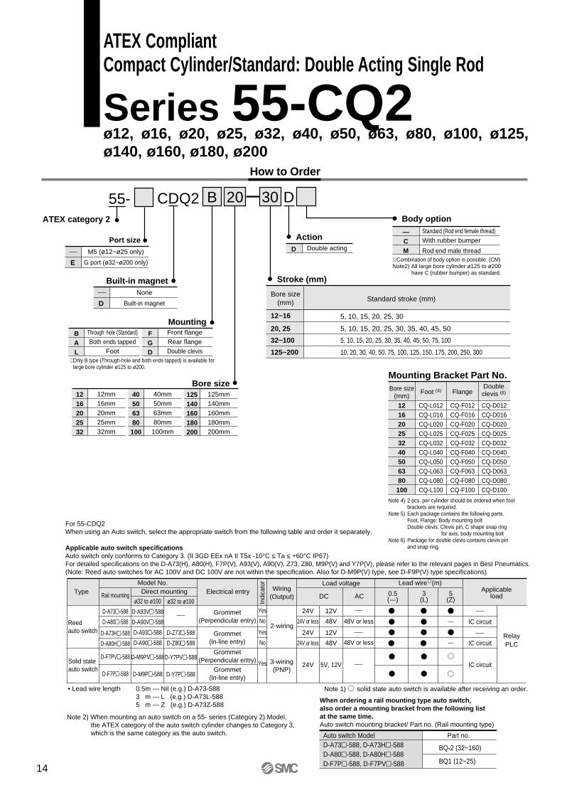
CDQ2 B 20 30 D
Built-in magnet
Mounting Bracket Part No.Bore size
(mm)Foot (4) Flange
121620253240506380
100
CQ-L012CQ-L016CQ-L020CQ-L025CQ-L032CQ-L040CQ-L050CQ-L063CQ-L080CQ-L100
CQ-F012CQ-F016CQ-F020CQ-F025CQ-F032CQ-F040CQ-F050CQ-F063CQ-F080CQ-F100
CQ-D012CQ-D016CQ-D020CQ-D025CQ-D032CQ-D040CQ-D050CQ-D063CQ-D080CQ-D100
Doubleclevis (6)
D Double acting
Mounting
Stroke (mm)
BAL
Through -hole (Standard)Both ends tapped
Foot
FGD
Front flangeRear flangeDouble clevis
1216202532
12mm16mm20mm25mm32mm
40506380100
40mm50mm63mm80mm100mm
Note 4) 2 pcs. per cylinder should be ordered when foot brackets are required.
Note 5) Each package contains the following parts.Foot, Flange: Body mounting boltDouble clevis: Clevis pin, C shape snap ring
for axis, body mounting boltNote 6) Package for double clevis contains clevis pin
and snap ring.
—CM
Standard (Rod end female thread)With rubber bumper
Rod end male thread∗ Combination of body option is possible. (CM)Note2) All large bore cylinder ø125 to ø200
have C (rubber bumper) as standard.
Action
Body option
Bore size
∗ Only B type (Through-hole and both ends tapped) is available for large bore cylinder ø125 to ø200.
Port size
E
M5 (ø12~ø25 only)
G port (ø32~ø200 only)
55-
Bore size(mm)
12~16
125~200
32~100
20, 25
Standard stroke (mm)
5, 10, 15, 20, 25, 30
5, 10, 15, 20, 25, 30, 35, 40, 45, 50
5, 10, 15, 20, 25, 30, 35, 40, 45, 50, 75, 100
10, 20, 30, 40, 50, 75, 100, 125, 150, 175, 200, 250, 300
ATEX category 2
D
None
Built-in magnet
TypeModel No.
Wiring(Output)
Load voltage
Indi
cato
r
Electrical entry ApplicableloadDC AC
Lead wire∗ (m)
0.5(—)
3(L)
5(Z)
Reedauto switch
Solid stateauto switch
Rail mounting
D-A73-588
D-A80-588
D-A73H-588
D-A80H-588
D-F7PV-588
D-F7P-588
Direct mounting
ø32 to ø100
D-A93V-588
D-A90V-588
D-A93-588
D-A90-588
D-M9PV-588
D-M9P-588
Grommet(Perpendicular entry)
Grommet(In-line entry)
Grommet(Perpendicular entry)
Grommet(In-line entry)
Yes
No
Yes
No
Yes
2-wiring
3-wiring(PNP)
24V
24V or less
24V
24V or less
24V
12V
48V
12V
48V
5V, 12V
48V or less
48V or less
IC circuit
IC circuit
IC circuit
RelayPLC
For 55-CDQ2When using an Auto switch, select the appropriate switch from the following table and order it separately.
Applicable auto switch specificationsAuto switch only conforms to Category 3. (II 3GD EEx nA II T5x -10°C ≤ Ta ≤ +60°C IP67)For detailed specifications on the D-A73(H), A80(H), F7P(V), A93(V), A90(V), Z73, Z80, M9P(V) and Y7P(V), please refer to the relevant pages in Best Pneumatics.(Note: Reed auto switches for AC 100V and DC 100V are not within the specification. Also for D-M9P(V) type, see D-F9P(V) type specifications)
Note 1) solid state auto switch is available after receiving an order.• Lead wire length 0.5m --- Nil (e.g.) D-A73-5883 m --- L (e.g.) D-A73L-5885 m --- Z (e.g.) D-A73Z-588
Note 2) When mounting an auto switch on a 55- series (Category 2) Model, the ATEX category of the auto switch cylinder changes to Category 3, which is the same category as the auto switch.
When ordering a rail mounting type auto switch,also order a mounting bracket from the following listat the same time.Auto switch mounting bracket/ Part no. (Rail mounting type)
Auto switch ModelD-A73-588, D-A73H-588D-A80-588, D-A80H-588D-F7P-588, D-F7PV-588
Part no.
BQ-2 (32~160)
BQ1 (12~25)
ø32 to ø100
D-Z73-588
D-Z80-588
D-Y7PV-588
D-Y7P-588
How to Order
14
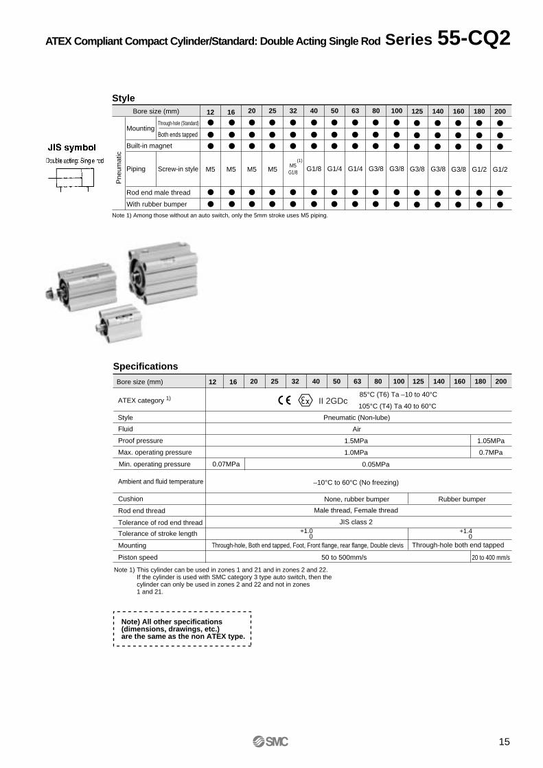
ATEX CompliantCompact Cylinder/Standard: Double Acting Single Rod
Series 55-CQ2 ø12, ø16, ø20, ø25, ø32, ø40, ø50, ø63, ø80, ø100, ø125,ø140, ø160, ø180, ø200
1.5MPa
1.0MPa
–10°C to 60°C (No freezing)
Male thread, Female thread
JIS class 2
Through-hole, Both end tapped, Foot, Front flange, rear flange, Double clevis
Note 1) Among those without an auto switch, only the 5mm stroke uses M5 piping.
StyleBore size (mm)
Pne
umat
ic
Mounting
Piping
Through-hole (Standard)
Both ends tapped
Built-in magnet
Rod end male thread
With rubber bumper
Screw-in style
12 16 20 25 32 40 50 63 80 100
M5 M5 M5 M5 G1/8 G1/4 G1/4 G3/8 G3/8
Fluid
Proof pressure
Max. operating pressure
Ambient and fluid temperature
Cushion
Rod end thread
Tolerance of rod end thread
Tolerance of stroke length
Mounting
Piston speed
Specifications
Style Pneumatic (Non-lube)
Air
None, rubber bumper
+1.0 0
M5G1/8
(1)
Bore size (mm) 12 16 20 25 32 40 50 63 80 100
50 to 500mm/s
125 140 160 180 200
1.05MPa
0.7MPa
20 to 400 mm/s
+1.40
Through-hole both end tapped
ATEX category 1)85°C (T6) Ta –10 to 40°C
105°C (T4) Ta 40 to 60°CII 2GDc
Note 1) This cylinder can be used in zones 1 and 21 and in zones 2 and 22.If the cylinder is used with SMC category 3 type auto switch, then the cylinder can only be used in zones 2 and 22 and not in zones 1 and 21.
Note) All other specifications (dimensions, drawings, etc.) are the same as the non ATEX type.
Rubber bumper
125 140 160 180
G3/8 G3/8 G3/8 G1/2
Min. operating pressure 0.07MPa 0.05MPa
200
G1/2
15
ATEX Compliant Compact Cylinder/Standard: Double Acting Single Rod Series 55-CQ2
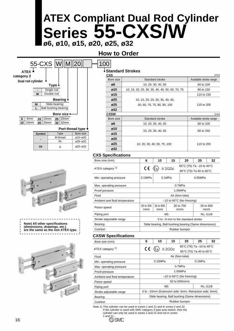
55-CXS M 10020
Dual rod cylinder
BearingSlide bearing
Ball bushing bearingML
W
TypeSingle rodDouble rod
-W
Standard Strokes
Bore size Standard stroke
10, 20, 30, 40, 50
10, 15, 20, 25, 30, 35, 40, 45, 50, 60, 70, 75
Available stroke range
60 to 100
80 to 150
110 to 150
110 to 200
10, 15, 20, 25, 30, 35, 40, 45,
50, 60, 70, 75, 80, 90, 100
ø6
ø10
ø15
ø20
ø25
ø32
(mm)CXS
Bore size Standard stroke
10, 20, 30, 40, 50
10, 20, 30, 40, 50
Available stroke range
60 to 100
60 to 150
110 to 20010, 20, 30, 40, 50, 75, 100
ø6
ø10
ø15
ø20
ø25
ø32
(mm)CXSW
Symbol
-
TF
TypeM thread
Rc
G
Port thread typeBore sizeø10~ø20ø25~ø32
ø25~ø32
Bore size (mm)
Min. operating pressure
Max. operating pressure
Proof pressure
Fluid
Ambient and fluid temperature
Piston speed
Piping port
Stroke adjustable range
Bearing
Cushion
6 10 15
0.7MPa
1.05MPa
Air (Non-lube)
–10 to 60°C (No freezing)
0 to –5 mm to the standard stroke
Slide bearing, Ball bushing bearing (Same dimensions)
Rubber bumper
20 25
30 to 300mm/s
30 to 800mm/s
30 to 700mm/s
30 to 600mm/s
M5 Rc, G1/8
0.15MPa 0.1MPa 0.05MPa
32
CXS Specifications
Bore size (mm)
Fluid
Min. operating pressure
Max. operating pressure
Proof pressure
Ambient and fluid temperature
Piston speed
Piping port
Stroke adjustable range
Bearing
Cushion
6 10 15
Air (Non-lube)
0.7MPa
1.05MPa
–10 to 60°C (No freezing)
50 to 500mm/s
0 to –10mm (Extension side: 5mm, Retraction side: 5mm)
Slide bearing, Ball bushing (Same dimensions)
Rubber bumper
0.15MPa 0.1MPa
20 25 32
CXSW Specifications
M5 Rc, G1/8
ATEX category 1)65°C (T6) Ta –10 to 40°C
85°C (T5) Ta 40 to 60°CII 2GDc
ATEX category 1)65°C (T6) Ta –10 to 40°C
85°C (T5) Ta 40 to 60°CII 2GDc
ATEXcategory 2
Note 1) This cylinder can be used in zones 1 and 21 and in zones 2 and 22.If the cylinder is used with SMC category 3 type auto switch, then the cylinder can only be used in zones 2 and 22 and not in zones 1 and 21.
Note) All other specifications (dimensions, drawings, etc.) are the same as the non ATEX type.
Bore size6mm10mm
610
15mm20mm
1520
25mm32mm
2532
16
ATEX Compliant Dual Rod Cylinder
Series 55-CXS/Wø6, ø10, ø15, ø20, ø25, ø32
How to Order
Type Model No. Wiring(Output)
Load voltage
Indi
cato
r
Electrical entry ApplicableloadDC AC
Lead wire∗ (m)
0.5(—)
3(L)
5(Z)
Reedauto switch
Solid stateauto switch
D-Z73-588
D-Z80-588
D-Y7P-588
D-Y7PV-588
Grommet(In-line)
Grommet(In-line)
Grommet(Perpendicular)
Yes
No
Yes
2-wiring
3-wiring(PNP)
24V 12V
IC circuit
IC circuit
RelayPLC
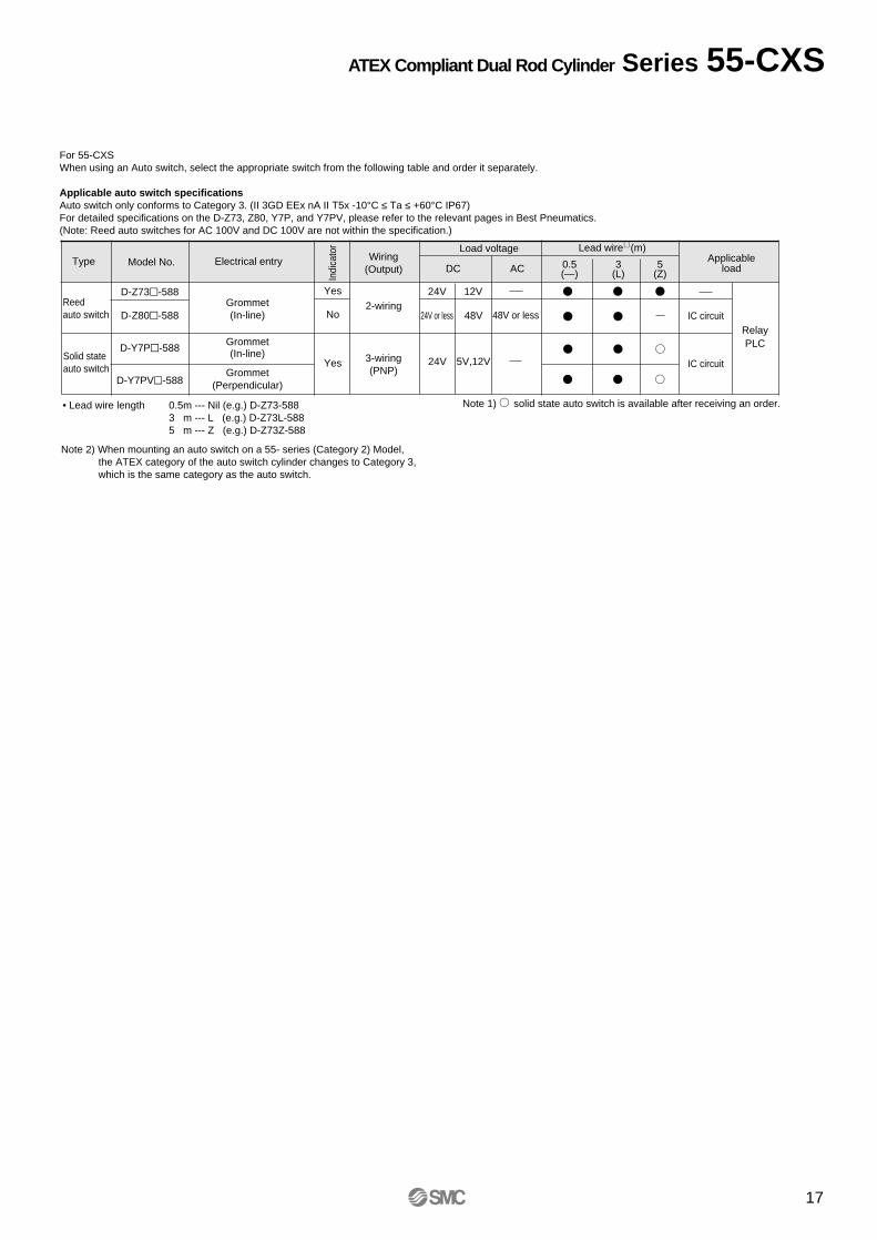
For 55-CXSWhen using an Auto switch, select the appropriate switch from the following table and order it separately.
Applicable auto switch specificationsAuto switch only conforms to Category 3. (II 3GD EEx nA II T5x -10°C ≤ Ta ≤ +60°C IP67)For detailed specifications on the D-Z73, Z80, Y7P, and Y7PV, please refer to the relevant pages in Best Pneumatics.(Note: Reed auto switches for AC 100V and DC 100V are not within the specification.)
Note 1) solid state auto switch is available after receiving an order.• Lead wire length 0.5m --- Nil (e.g.) D-Z73-5883 m --- L (e.g.) D-Z73L-5885 m --- Z (e.g.) D-Z73Z-588
Note 2) When mounting an auto switch on a 55- series (Category 2) Model, the ATEX category of the auto switch cylinder changes to Category 3, which is the same category as the auto switch.
24V 5V,12V
24V or less 48V 48V or less
17
ATEX Compliant Dual Rod Cylinder Series 55-CXS
How to Order
101620253240506380
100
10mm16mm20mm25mm32mm40mm50mm63mm80mm
100mm
Bore size
StrokeBasic type
Symbol
-
TNTF
TypeM thread
RcNPT
G
Piping thread
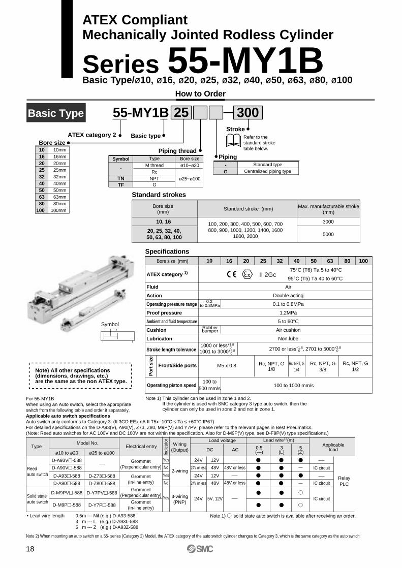
Basic Type 55-MY1B 30025
Refer to the standard stroke table below.
Standard strokes
Bore size (mm)
20, 25, 32, 40,50, 63, 80, 100
Standard stroke (mm)
100, 200, 300, 400, 500, 600, 700800, 900, 1000, 1200, 1400, 1600
1800, 2000
3000
5000
Max. manufacturable stroke (mm)
Bore sizeø10~ø20
ø25~ø100
SpecificationsBore size (mm)
Fluid
Action
Operating pressure range
Proof pressure
Ambient and fluid temperature
Cushion
Lubricaton
Stroke length tolerance
Front/Side ports
1610 20 25 32 40 50 63 80 100
Air
Double acting
0.1 to 0.8MPa
1.2MPa
5 to 60°C
Air cushion
Non-lube1000 or less+1.8
1001 to 3000+2.80
02700 or less+1.8, 2701 to 5000+2.8
0 0
M5 x 0.8 Rc, NPT, G1/8
Rc, NPT, G1/4
Rc, NPT, G3/8
Rc, NPT, G1/2
Symbol
0.2 to 0.8MPa
Rubberbumper
Por
t siz
e
10, 16
ATEX category 1) 75°C (T6) Ta 5 to 40°C
95°C (T5) Ta 40 to 60°CII 2Gc
Operating piston speed100 to
500 mm/s100 to 1000 mm/s
Note 1) This cylinder can be used in zone 1 and 2.If the cylinder is used with SMC category 3 type auto switch, then the cylinder can only be used in zone 2 and not in zone 1.
Note) All other specifications (dimensions, drawings, etc.) are the same as the non ATEX type.
ATEX category 2
-G
Standard typeCentralized piping type
Piping
For 55-MY1BWhen using an Auto switch, select the appropriateswitch from the following table and order it separately.Applicable auto switch specificationsAuto switch only conforms to Category 3. (II 3GD EEx nA II T5x -10°C ≤ Ta ≤ +60°C IP67)For detailed specifications on the D-A93(V), A90(V), Z73, Z80, M9P(V) and Y7PV, please refer to the relevant pages in Best Pneumatics.(Note: Reed auto switches for AC 100V and DC 100V are not within the specification. Also for D-M9P(V) type, see D-F9P(V) type specifications.)
TypeModel No. Wiring
(Output)
Load voltage
Indi
cato
r
Electrical entry ApplicableloadDC AC
Lead wire∗ (m)
0.5(—)
3(L)
5(Z)
Reedauto switch
Solid stateauto switch
ø10 to ø20
D-A93V-588
D-A90V-588
D-A93-588
D-A90-588
D-M9PV-588
D-M9P-588
ø25 to ø100
D-Z73-588
D-Z80-588
D-Y7PV-588
D-Y7P-588
Grommet(Perpendicular entry)
Grommet(In-line entry)
Grommet(Perpendicular entry)
Grommet(In-line entry)
Yes
No
Yes
No
Yes
2-wiring
3-wiring(PNP)
24V
24V or less
24V
24V or less
24V
12V
48V
12V
48V
5V, 12V
48V or less
48V or less
IC circuit
IC circuit
IC circuit
RelayPLC
Note 1) solid state auto switch is available after receiving an order.• Lead wire length 0.5m --- Nil (e.g.) D-A93-5883 m --- L (e.g.) D-A93L-5885 m --- Z (e.g.) D-A93Z-588
Note 2) When mounting an auto switch on a 55- series (Category 2) Model, the ATEX category of the auto switch cylinder changes to Category 3, which is the same category as the auto switch.
18
ATEX CompliantMechanically Jointed Rodless Cylinder
Series 55-MY1BBasic Type/ø10, ø16, ø20, ø25, ø32, ø40, ø50, ø63, ø80, ø100
How to Order
16202532405063
16mm20mm25mm32mm40mm50mm63mm
Bore size
Slide bearingguide type
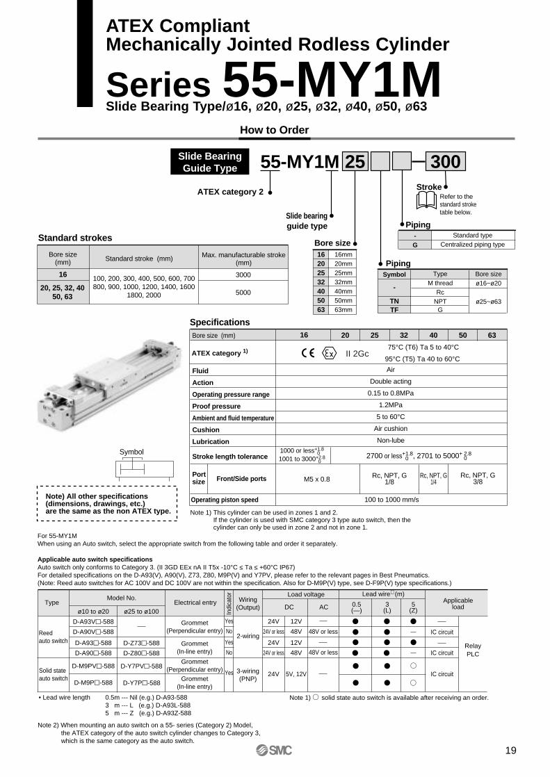
Slide BearingGuide Type 55-MY1M 30025
StrokeRefer to the standard stroke table below.
Symbol
-
TNTF
TypeM thread
RcNPT
G
PipingBore sizeø16~ø20
ø25~ø63
16
20, 25, 32, 4050, 63
100, 200, 300, 400, 500, 600, 700800, 900, 1000, 1200, 1400, 1600
1800, 2000
3000
5000
Standard strokes
Bore size (mm) Standard stroke (mm) Max. manufacturable stroke
(mm)
Specifications16 20 25 32 40 50 63
1000 or less+1.8
1001 to 3000+2.80
02700 or less+1.8, 2701 to 5000+ 2.8
0 0
M5 x 0.8 Rc, NPT, G1/8
Rc, NPT, G1/4
Rc, NPT, G3/8
Bore size (mm)
Fluid
Action
Operating pressure range
Proof pressure
Ambient and fluid temperature
Cushion
Lubrication
Stroke length tolerance
Front/Side portsPortsize
Air
Double acting
0.15 to 0.8MPa
1.2MPa
5 to 60°C
Air cushion
Non-lube
Symbol
ATEX category 1) 75°C (T6) Ta 5 to 40°C
95°C (T5) Ta 40 to 60°CII 2Gc
Operating piston speed 100 to 1000 mm/s
-G
Standard typeCentralized piping type
Piping
ATEX category 2
Note 1) This cylinder can be used in zones 1 and 2.If the cylinder is used with SMC category 3 type auto switch, then the cylinder can only be used in zone 2 and not in zone 1.
Note) All other specifications (dimensions, drawings, etc.) are the same as the non ATEX type.
For 55-MY1MWhen using an Auto switch, select the appropriate switch from the following table and order it separately.
Applicable auto switch specificationsAuto switch only conforms to Category 3. (II 3GD EEx nA II T5x -10°C ≤ Ta ≤ +60°C IP67)For detailed specifications on the D-A93(V), A90(V), Z73, Z80, M9P(V) and Y7PV, please refer to the relevant pages in Best Pneumatics.(Note: Reed auto switches for AC 100V and DC 100V are not within the specification. Also for D-M9P(V) type, see D-F9P(V) type specifications.)
TypeModel No. Wiring
(Output)
Load voltage
Indi
cato
r
Electrical entry ApplicableloadDC AC
Lead wire∗ (m)
0.5(—)
3(L)
5(Z)
Reedauto switch
Solid stateauto switch
ø10 to ø20
D-A93V-588
D-A90V-588
D-A93-588
D-A90-588
D-M9PV-588
D-M9P-588
ø25 to ø100
D-Z73-588
D-Z80-588
D-Y7PV-588
D-Y7P-588
Grommet(Perpendicular entry)
Grommet(In-line entry)
Grommet(Perpendicular entry)
Grommet(In-line entry)
Yes
No
Yes
No
Yes
2-wiring
3-wiring(PNP)
24V
24V or less
24V
24V or less
24V
12V
48V
12V
48V
5V, 12V
48V or less
48V or less
IC circuit
IC circuit
IC circuit
RelayPLC
Note 1) solid state auto switch is available after receiving an order.• Lead wire length 0.5m --- Nil (e.g.) D-A93-5883 m --- L (e.g.) D-A93L-5885 m --- Z (e.g.) D-A93Z-588
Note 2) When mounting an auto switch on a 55- series (Category 2) Model, the ATEX category of the auto switch cylinder changes to Category 3, which is the same category as the auto switch.
19
ATEX CompliantMechanically Jointed Rodless Cylinder
Series 55-MY1MSlide Bearing Type/ø16, ø20, ø25, ø32, ø40, ø50, ø63
101620253240
10mm16mm20mm25mm32mm40mm
High precisionguide type
How to Order
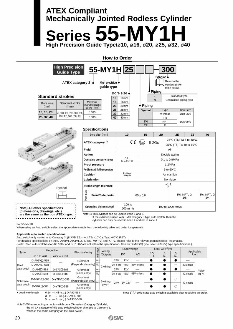
High PrecisionGuide Type 55-MY1H 25
Bore size
StrokeRefer to the standard stroke table below.
Symbol
-
TNTF
TypeM thread
RcNPT
G
PipingBore sizeø10~ø20
ø25~ø40
Bore size(mm)
10, 16, 20
25, 32, 40
Standard stroke(mm)
50, 100, 150, 200, 300, 350, 400, 450, 500, 550, 600
1000
1500
Maximum manufacturable
stroke (mm)
Standard strokes
1610 20 25 32 40
+1.80
M5 x 0.8 Rc, NPT, G1/8
Symbol
Rc, NPT, G1/4
SpecificationsBore size (mm)
Fluid
Action
Operating pressure range
Proof pressure
Ambient and fluid temperature
Cushion
Lubrication
Stroke length tolerance
Front/Side ports
Por
t siz
e
Air
Double acting
0.1 to 0.8MPa
1.2MPa
5 to 60°C
Air cushion
Non-lube
0.2 to 0.8MPa
Rubberbumper
ATEX category 1) 75°C (T6) Ta 5 to 40°C
95°C (T5) Ta 40 to 60°CII 2Gc
Operating piston speed100 to
500 mm/s100 to 1000 mm/s
ATEX category 2
Note 1) This cylinder can be used in zone 1 and 2.If the cylinder is used with SMC category 3 type auto switch, then the cylinder can only be used in zone 2 and not in zone 1.
Note) All other specifications (dimensions, drawings, etc.) are the same as the non ATEX type.
-G
Standard typeCentralized piping type
Piping
300
For 55-MY1HWhen using an Auto switch, select the appropriate switch from the following table and order it separately.
Applicable auto switch specificationsAuto switch only conforms to Category 3. (II 3GD EEx nA II T5x -10°C ≤ Ta ≤ +60°C IP67)For detailed specifications on the D-A93(V), A90(V), Z73, Z80, M9P(V) and Y7PV, please refer to the relevant pages in Best Pneumatics.(Note: Reed auto switches for AC 100V and DC 100V are not within the specification. Also for D-M9P(V) type, see D-F9P(V) type specifications.)
TypeModel No. Wiring
(Output)
Load voltage
Indi
cato
r
Electrical entry ApplicableloadDC AC
Lead wire∗ (m)
0.5(—)
3(L)
5(Z)
Reedauto switch
Solid stateauto switch
ø10 to ø20
D-A93V-588
D-A90V-588
D-A93-588
D-A90-588
D-M9PV-588
D-M9P-588
ø25 to ø100
D-Z73-588
D-Z80-588
D-Y7PV-588
D-Y7P-588
Grommet(Perpendicular entry)
Grommet(In-line entry)
Grommet(Perpendicular entry)
Grommet(In-line entry)
Yes
No
Yes
No
Yes
2-wiring
3-wiring(PNP)
24V
24V or less
24V
24V or less
24V
12V
48V
12V
48V
5V, 12V
48V or less
48V or less
IC circuit
IC circuit
IC circuit
RelayPLC
Note 1) solid state auto switch is available after receiving an order.• Lead wire length 0.5m --- Nil (e.g.) D-A93-5883 m --- L (e.g.) D-A93L-5885 m --- Z (e.g.) D-A93Z-588
Note 2) When mounting an auto switch on a 55- series (Category 2) Model, the ATEX category of the auto switch cylinder changes to Category 3, which is the same category as the auto switch.
20
ATEX CompliantMechanically Jointed Rodless Cylinder
Series 55-MY1HHigh Precision Guide Type/ø10, ø16, ø20, ø25, ø32, ø40

21
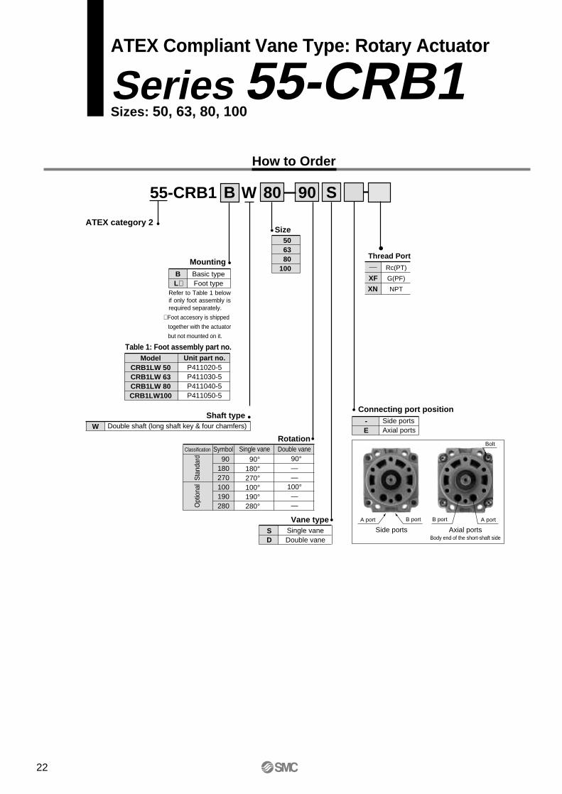
ATEX Compliant Vane Type: Rotary Actuator
Series 55-CRB1Sizes: 50, 63, 80, 100
How to Order
55-CRB1 80WB S90
506380
100Mounting
BL∗
Basic typeFoot type
Rotation
Shaft typeW Double shaft (long shaft key & four chamfers)
Vane typeSD
Single vaneDouble vane
Size
Connecting port position-E
Side portsAxial ports
Classification Symbol Single vane Double vane
Sta
ndar
dO
ptio
nal
90180270100190280
90°180°270°100°190°280°
90°——
100°——
Table 1: Foot assembly part no.Model
CRB1LW 50CRB1LW 63CRB1LW 80CRB1LW100
Unit part no.P411020-5P411030-5P411040-5P411050-5
Bolt
A portB portB portA port
Side ports Axial portsBody end of the short-shaft side
Refer to Table 1 below if only foot assembly is required separately.
Thread Port
∗ Foot accesory is shipped
together with the actuator
but not mounted on it.
XF
XN
Rc(PT)
G(PF)
NPT
ATEX category 2
22

Specifications
JIS symbol
Model (Size)
Single vane (S)
90° , 180° , 270°
Double vane (D)
90°
100°
Vane type
Rotation
Fluid
Proof pressure (MPa)
Ambientand fluid temperature
Max. operatingpressure (MPa)
Min. operatingpressure (MPa)
Speed regulationrange (sec/90°)Allowable kineticenergy (J)
Shaftload
Bearing type
Port position
Size
Mounting
Allowableradial load (N)
Allowablethrust load (N)
Side ports
Axial ports
Standard
Optional
CRB1BW50 CRB1BW63 CRB1BW80 CRB1BW100 CRB1BW50 CRB1BW63 CRB1BW80 CRB1BW100
Air (non-lube)
1.5MPa
5° to 60°C
1.0MPa
0.15MPa
0.1 to 1
Ball bearing
Side ports or axial ports
Basic, Foot
Rc, NPT, G 1/8 Rc, NPT, G 1/4 Rc, NPT, G 1/8 Rc, NPT, G 1/4
Rc, NPT, G 1/8 Rc, NPT, G 1/4 Rc, NPT, G 1/8 Rc, NPT, G 1/4
0.082
245
196
0.398
490
490
0.12
390
340
0.6
588
539
0.112
245
196
0.16
390
340
0.54
490
490
0.811
588
539
Size: 100
Size: 50
Size: 80
Rotary ActuatorVane Type Series 55-CRB1
+4 0
100° , 190° , 280°
+4 0
+4 0
+4 0
+4 0
+4 0
+4 0
+4 0
Rad
ial f
orc
e
Thrust force
Note) All other specifications (dimensions, drawings, etc.) are the same as the non ATEX type.
Note 1) This actuator can be used in zones 1 and 2.
ATEX category 1) 90°C (T5) Ta 5 to 40°C
110°C (T4) Ta 40 to 60°CII 2GDc
23
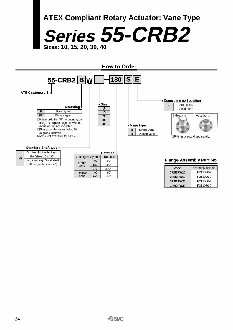
ATEX Compliant Rotary Actuator: Vane Type
Series 55-CRB2Sizes: 10, 15, 20, 30, 40
How to Order
Size1015203040
55-CRB2 10WB 180 S E
MountingBF1)
Basic typeFlange type
RotationVane type Symbol Rotation
Singlevane
Doublevane
9018027090
100
90°180°270°90°
100°
Connecting port position-E
Side portsAxial ports
Side ports
∗ Fittings are sold separately.
∗ When ordering "F" mounting type, flange is shipped together with the actuator, but not mounted.∗ Flange can be mounted at 60 degrees intervals.Note1) Not available for size 40.
Standard Shaft type
W
Double shaft with single flat (sizes 10 to 30)
Long shaft key, Short shaft with single flat (size 40)
Vane typeSD
Single vaneDouble vane
Axial ports
Flange Assembly Part No.
Model
CRB2FW10
CRB2FW15
CRB2FW20
CRB2FW30
Assembly part no.
P211070-2
P211090-2
P211060-2
P211080-2
ATEX category 2
24
Rad
ial f
orc
e
Thrust force
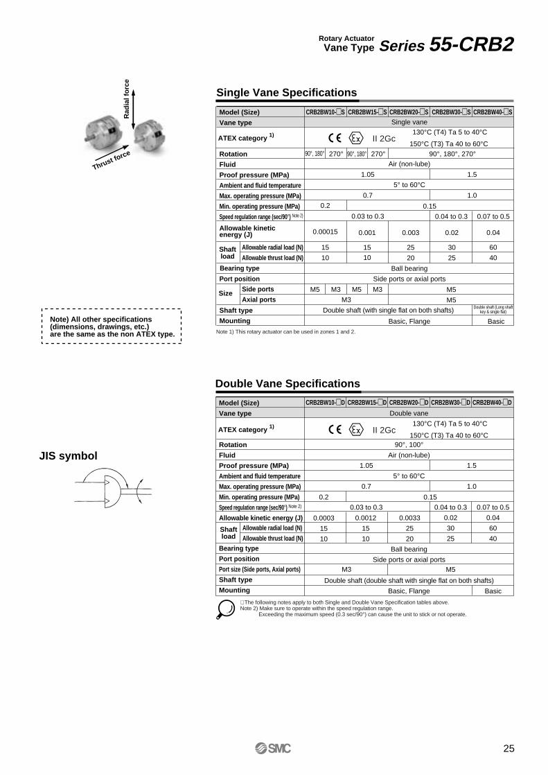
Single Vane Specifications
Double Vane Specifications
Rotary ActuatorVane Type Series 55-CRB2
Model (Size)
Vane type
Rotation
Fluid
Proof pressure (MPa)
Ambient and fluid temperature
Max. operating pressure (MPa)
Min. operating pressure (MPa)
Speed regulation range (sec/90°) Note 2)
Allowable kineticenergy (J)
Port position
Shaft type
Mounting
Allowable radial load (N)
Allowable thrust load (N)
Bearing type
Side ports
Axial ports
CRB2BW10-S CRB2BW15-S CRB2BW20-S CRB2BW30-S CRB2BW40-S
CRB2BW10-D CRB2BW15-D CRB2BW20-D CRB2BW30-D CRB2BW40-D
Single vane
Air (non-lube)
5° to 60°C
Ball bearing
Side ports or axial ports
Basic, Flange
0.2
0.00015
15
10
90°, 180° 270° 90°, 180° 270° 90°, 180°, 270°
1.05
0.7
0.03 to 0.3
1.5
1.0
0.001
15
10
0.003
25
20
0.02
30
25
0.04
60
40
Double shaft (Long shaftkey & single flat)
Basic
M3
M5
M5
0.15
Model (Size)
Vane type
Rotation
Fluid
Proof pressure (MPa)
Ambient and fluid temperature
Max. operating pressure (MPa)
Min. operating pressure (MPa)
Speed regulation range (sec/90°) Note 2)
Allowable kinetic energy (J)
Bearing type
Port position
Port size (Side ports, Axial ports)
Shaft type
Mounting
Allowable radial load (N)
Allowable thrust load (N)
Double vane
90°, 100°Air (non-lube)
5° to 60°C
Ball bearing
Side ports or axial ports
Double shaft (double shaft with single flat on both shafts)
Basic, Flange
0.2
0.0003
15
10
1.05
0.7
0.03 to 0.3
1.5
1.0
0.04 to 0.3
0.02
30
25
0.07 to 0.5
0.04
60
40
0.0012
15
10
0.0033
25
20
0.15
M5 M3 M5 M3
M3 M5
JIS symbol
0.04 to 0.3 0.07 to 0.5
Double shaft (with single flat on both shafts)
Size
∗ The following notes apply to both Single and Double Vane Specification tables above.Note 2) Make sure to operate within the speed regulation range.
Exceeding the maximum speed (0.3 sec/90°) can cause the unit to stick or not operate.
Shaftload
Shaftload
Note) All other specifications (dimensions, drawings, etc.) are the same as the non ATEX type.
ATEX category 1) 130°C (T4) Ta 5 to 40°C
150°C (T3) Ta 40 to 60°CII 2Gc
ATEX category 1) 130°C (T4) Ta 5 to 40°C
150°C (T3) Ta 40 to 60°CII 2Gc
Note 1) This rotary actuator can be used in zones 1 and 2.
Basic
25
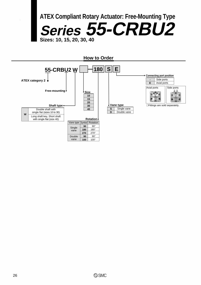
ATEX Compliant Rotary Actuator: Free-Mounting Type
Series 55-CRBU2Sizes: 10, 15, 20, 30, 40
How to Order
W
1015203040
55-CRBU2 10 180 S E
Free-mounting
Shaft type
RotationVane type Symbol Rotation
Singlevane
Doublevane
90180270
90100
90°180°270°
90°100°
Connecting port position-E
Side portsAxial ports
Axial ports
∗ Fittings are sold separately.Vane typeSD
Single vaneDouble vane
W
Double shaft withsingle flat (sizes 10 to 30)
Long shaft key, Short shaftwith single flat (size 40)
Side ports
Size
ATEX category 2
26
Rad
ial f
orc
e
Thrust force
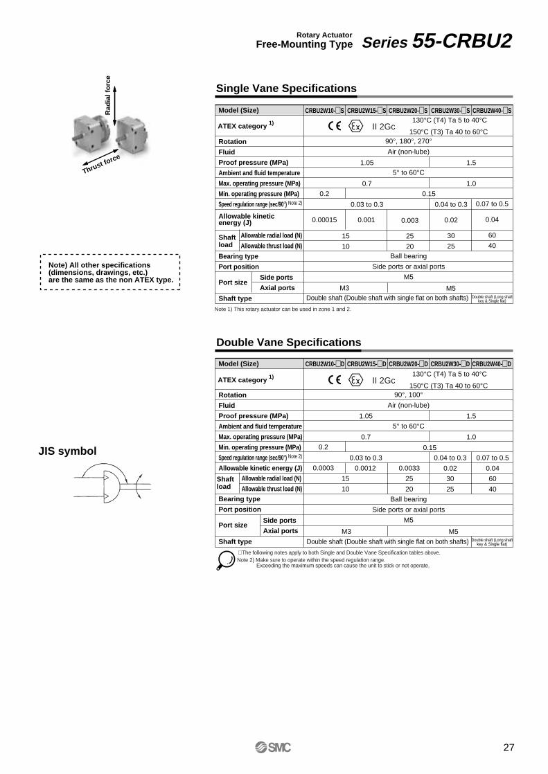
Single Vane Specifications
Double Vane Specifications
Rotary ActuatorFree-Mounting Type Series 55-CRBU2
Model (Size)
Rotation
Fluid
Proof pressure (MPa)
Ambient and fluid temperature
Max. operating pressure (MPa)
Min. operating pressure (MPa)
Speed regulation range (sec/90°) Note 2)
Allowable kineticenergy (J)
Shaftload
Bearing type
Port position
Port size
Shaft type
Allowable radial load (N)
Allowable thrust load (N)
CRBU2W10-S CRBU2W15-S CRBU2W20-S CRBU2W30-S CRBU2W40-S
CRBU2W10-D CRBU2W15-D CRBU2W20-D CRBU2W30-D CRBU2W40-D
90°, 180°, 270°Air (non-lube)
5° to 60°C
Ball bearing
Side ports or axial ports
M5
0.2
0.00015
1.05
0.7
0.03 to 0.3
1.5
1.0
0.001 0.003
25
20
0.04 to 0.3
0.02
30
25
0.07 to 0.5
0.04
60
40
Double shaft (Long shaftkey & Single flat)Double shaft (Double shaft with single flat on both shafts)
0.15
Model (Size)
Rotation
Fluid
Proof pressure (MPa)
Ambient and fluid temperature
Max. operating pressure (MPa)
Min. operating pressure (MPa)
Speed regulation range (sec/90°) Note 2)
Allowable kinetic energy (J)
Shaftload
Bearing type
Port position
Port size
Shaft type
Allowable radial load (N)
Allowable thrust load (N)
90°, 100°Air (non-lube)
5° to 60°C
Ball bearing
Side ports or axial ports
M5
0.2
0.0003
15
10
1.05
0.7
0.03 to 0.3
1.5
1.0
0.04 to 0.3
0.02
30
25
0.07 to 0.5
0.04
60
40
0.0012 0.0033
25
20
0.15JIS symbol
Double shaft (Double shaft with single flat on both shafts) Double shaft (Long shaftkey & Single flat)
15
10
∗ The following notes apply to both Single and Double Vane Specification tables above.Note 2) Make sure to operate within the speed regulation range.
Exceeding the maximum speeds can cause the unit to stick or not operate.
Note) All other specifications (dimensions, drawings, etc.) are the same as the non ATEX type.
ATEX category 1) 130°C (T4) Ta 5 to 40°C
150°C (T3) Ta 40 to 60°CII 2Gc
ATEX category 1) 130°C (T4) Ta 5 to 40°C
150°C (T3) Ta 40 to 60°CII 2Gc
Note 1) This rotary actuator can be used in zone 1 and 2.
Side ports
Axial ports M5M3
Side ports
Axial ports M3 M5
27
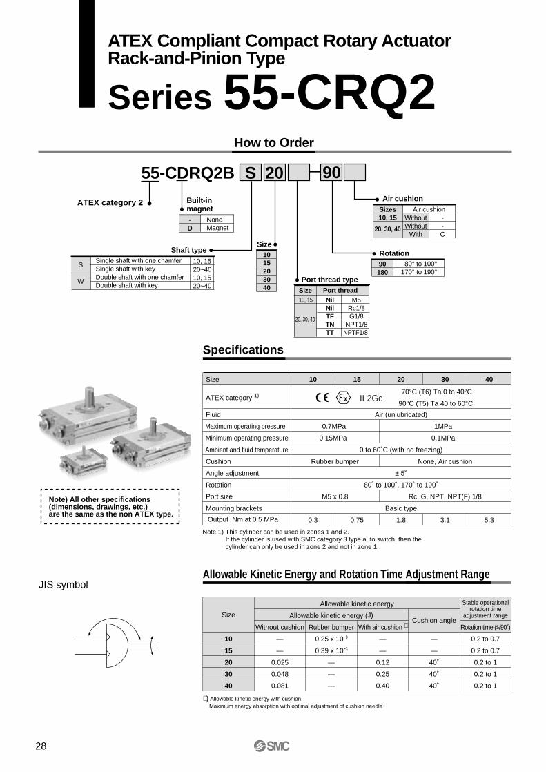
How to Order
55-CDRQ2B
Shaft type
Built-inmagnet
S 20
Size
Single shaft with one chamferSingle shaft with keyDouble shaft with one chamferDouble shaft with key
S
W
1015203040
90
Rotation90 80° to 100°
170° to 190°180
Air cushionSizes10, 15
20, 30, 40
Air cushionWithoutWithout
With
--C
Port thread type
10, 15
20, 30, 40
NilNilTFTNTT
M5Rc1/8G1/8
NPT1/8NPTF1/8
10, 1520~4010, 1520~40
Size Port thread
Specifications
Allowable Kinetic Energy and Rotation Time Adjustment Range
Fluid
Maximum operating pressure
Minimum operating pressure
Ambient and fluid temperature
Cushion
Angle adjustment
Rotation
Port size
Mounting brackets
Output Nm at 0.5 MPa
10
Air (unlubricated)
0.7MPa
0.15MPa
0 to 60˚C (with no freezing)
Rubber bumper
± 5˚
80˚ to 100˚, 170˚ to 190˚
M5 x 0.8
Basic type
0.3
15
0.75
20
1MPa
0.1MPa
None, Air cushion
Rc, G, NPT, NPT(F) 1/8
1.8
30
3.1
40
5.3
Size
10
15
20
30
40
Allowable kinetic energy
Allowable kinetic energy (J)
Without cushion
—
—
0.025
0.048
0.081
Rubber bumper
0.25 x 10-³
0.39 x 10-³
—
—
—
With air cushion ∗
—
—
0.12
0.25
0.40
Cushion angle
—
—
40˚
40˚
40˚
Stable operational rotation time
adjustment range
Rotation time (s/90 )
0.2 to 0.7
0.2 to 0.7
0.2 to 1
0.2 to 1
0.2 to 1
Size
JIS symbol
∗) Allowable kinetic energy with cushionMaximum energy absorption with optimal adjustment of cushion needle
ATEX category 1)70°C (T6) Ta 0 to 40°C
90°C (T5) Ta 40 to 60°CII 2Gc
ATEX category 2
Note 1) This cylinder can be used in zones 1 and 2.If the cylinder is used with SMC category 3 type auto switch, then the cylinder can only be used in zone 2 and not in zone 1.
Note) All other specifications (dimensions, drawings, etc.) are the same as the non ATEX type.
- NoneMagnetD
28
ATEX Compliant Compact Rotary ActuatorRack-and-Pinion Type
Series 55-CRQ2
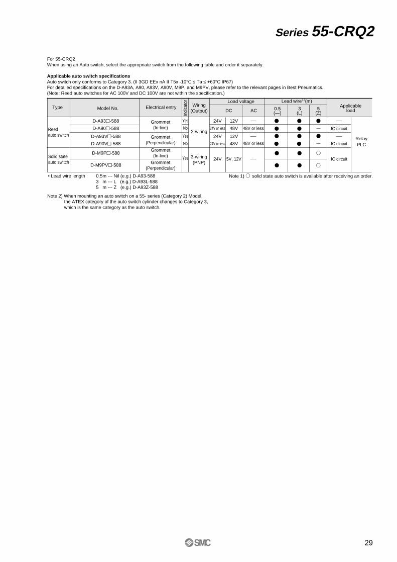
For 55-CRQ2When using an Auto switch, select the appropriate switch from the following table and order it separately.
Applicable auto switch specificationsAuto switch only conforms to Category 3. (II 3GD EEx nA II T5x -10°C ≤ Ta ≤ +60°C IP67)For detailed specifications on the D-A93A, A90, A93V, A90V, M9P, and M9PV, please refer to the relevant pages in Best Pneumatics.(Note: Reed auto switches for AC 100V and DC 100V are not within the specification.)
Type Model No.Wiring
(Output)
Load voltage
Indi
cato
r
Electrical entry ApplicableloadDC AC
Lead wire∗ (m)
0.5(—)
3(L)
5(Z)
Reedauto switch
Solid stateauto switch
D-A93-588
D-A90-588
D-A93V-588
D-A90V-588
D-M9P-588
D-M9PV-588
Grommet(In-line)
Grommet(Perpendicular)
Grommet(In-line)
Grommet(Perpendicular)
Yes
No
Yes
No
Yes
2-wiring
3-wiring(PNP)
24V
24V or less
24V
24V or less
24V
12V
48V
12V
48V
5V, 12V
48V or less
48V or less
IC circuit
IC circuit
IC circuit
RelayPLC
Note 1) solid state auto switch is available after receiving an order.• Lead wire length 0.5m --- Nil (e.g.) D-A93-5883 m --- L (e.g.) D-A93L-5885 m --- Z (e.g.) D-A93Z-588
Note 2) When mounting an auto switch on a 55- series (Category 2) Model, the ATEX category of the auto switch cylinder changes to Category 3, which is the same category as the auto switch.
Series 55-CRQ2
29
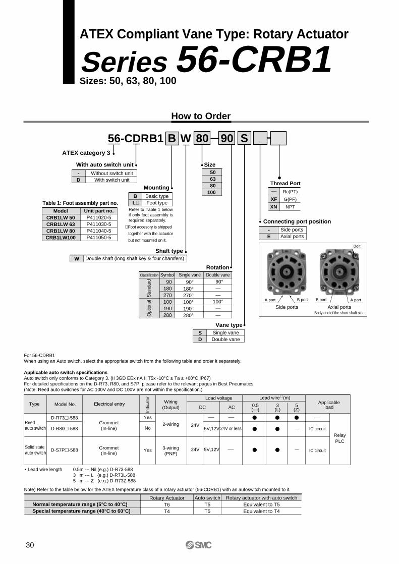
ATEX Compliant Vane Type: Rotary Actuator
Series 56-CRB1Sizes: 50, 63, 80, 100
How to Order
56-CDRB1 80WB S90
506380
100Mounting
BL∗
Basic typeFoot type
Rotation
Shaft typeW Double shaft (long shaft key & four chamfers)
Vane typeSD
Single vaneDouble vane
Size
Connecting port position-E
Side portsAxial ports
Classification Symbol Single vane Double vane
Sta
ndar
dO
ptio
nal
90180270100190280
90°180°270°100°190°280°
90°——
100°——
Table 1: Foot assembly part no.Model
CRB1LW 50CRB1LW 63CRB1LW 80CRB1LW100
Unit part no.P411020-5P411030-5P411040-5P411050-5
Bolt
A portB portB portA port
Side ports Axial portsBody end of the short-shaft side
Refer to Table 1 below if only foot assembly is required separately.
Thread Port
∗ Foot accesory is shipped
together with the actuator
but not mounted on it.
XF
XN
Rc(PT)
G(PF)
NPT
ATEX category 3
With auto switch unit-D
Without switch unitWith switch unit
For 56-CDRB1When using an Auto switch, select the appropriate switch from the following table and order it separately.
Applicable auto switch specificationsAuto switch only conforms to Category 3. (II 3GD EEx nA II T5x -10°C ≤ Ta ≤ +60°C IP67)For detailed specifications on the D-R73, R80, and S7P, please refer to the relevant pages in Best Pneumatics.(Note: Reed auto switches for AC 100V and DC 100V are not within the specification.)
Type Model No. Wiring(Output)
Load voltage
Indi
cato
r
Electrical entry ApplicableloadDC AC
Lead wire∗ (m)
0.5(—)
3(L)
5(Z)
Reedauto switch
Solid stateauto switch
D-R73-588
D-R80-588
D-S7P-588
Grommet(In-line)
Grommet(In-line)
Yes
No
Yes
2-wiring
3-wiring(PNP)
24VIC circuit
IC circuit
RelayPLC
• Lead wire length 0.5m --- Nil (e.g.) D-R73-5883 m --- L (e.g.) D-R73L-5885 m --- Z (e.g.) D-R73Z-588
Note) Refer to the table below for the ATEX temperature class of a rotary actuator (56-CDRB1) with an autoswitch mounted to it.
24V 5V,12V
5V,12V 24V or less
Normal temperature range (5°C to 40°C)Special temperature range (40°C to 60°C)
Rotary ActuatorT6T4
Auto switchT5T5
Rotary actuator with auto switchEquivalent to T5Equivalent to T4
30
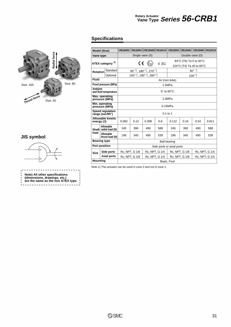
Specifications
JIS symbol
Model (Size)
Single vane (S)
90° , 180° , 270°
Double vane (D)
90°
100°
Vane type
Rotation
Fluid
Proof pressure (MPa)
Ambientand fluid temperature
Max. operatingpressure (MPa)
Min. operatingpressure (MPa)
Speed regulationrange (sec/90°)Allowable kineticenergy (J)
Shaftload
Bearing type
Port position
Size
Mounting
Allowableradial load (N)
Allowablethrust load (N)
Side ports
Axial ports
Standard
Optional
CRB1BW50 CRB1BW63 CRB1BW80 CRB1BW100 CRB1BW50 CRB1BW63 CRB1BW80 CRB1BW100
Air (non-lube)
1.5MPa
5° to 60°C
1.0MPa
0.15MPa
0.1 to 1
Ball bearing
Side ports or axial ports
Basic, Foot
Rc, NPT, G 1/8 Rc, NPT, G 1/4 Rc, NPT, G 1/8 Rc, NPT, G 1/4
Rc, NPT, G 1/8 Rc, NPT, G 1/4 Rc, NPT, G 1/8 Rc, NPT, G 1/4
0.082
245
196
0.398
490
490
0.12
390
340
0.6
588
539
0.112
245
196
0.16
390
340
0.54
490
490
0.811
588
539
Size: 100
Size: 50
Size: 80
Rotary ActuatorVane Type Series 56-CRB1
+4 0
100° , 190° , 280°
+4 0
+4 0
+4 0
+4 0
+4 0
+4 0
+4 0
Rad
ial f
orc
e
Thrust force
Note) All other specifications (dimensions, drawings, etc.) are the same as the non ATEX type.
Note 1) This actuator can be used in zone 2 and not in zone 1.
ATEX category 1) 84°C (T6) Ta 5 to 40°C
104°C (T4) Ta 40 to 60°CII 3G
31
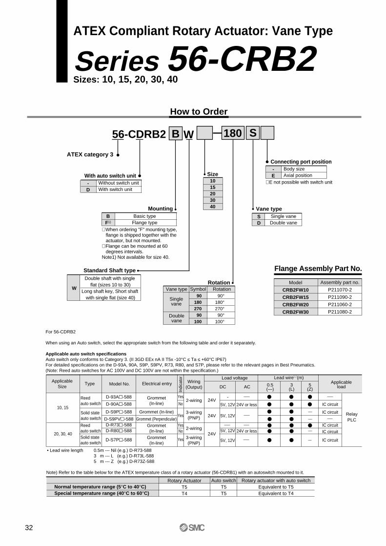
ATEX Compliant Rotary Actuator: Vane Type
Series 56-CRB2Sizes: 10, 15, 20, 30, 40
How to Order
Size1015203040
56-CDRB2 10WB 180 S
MountingBF1)
Basic typeFlange type
RotationVane type Symbol Rotation
Singlevane
Doublevane
9018027090
100
90°180°270°90°
100°
With auto switch unit-D
Without switch unitWith switch unit
∗ When ordering "F" mounting type, flange is shipped together with the actuator, but not mounted.∗ Flange can be mounted at 60 degrees intervals.Note1) Not available for size 40.
Standard Shaft type
W
Double shaft with single flat (sizes 10 to 30)
Long shaft key, Short shaft with single flat (size 40)
Vane typeSD
Single vaneDouble vane
Flange Assembly Part No.
Model
CRB2FW10
CRB2FW15
CRB2FW20
CRB2FW30
Assembly part no.
P211070-2
P211090-2
P211060-2
P211080-2
ATEX category 3Connecting port position-E
Body sizeAxial position
∗ E not possible with switch unit
Note) Refer to the table below for the ATEX temperature class of a rotary actuator (56-CDRB1) with an autoswitch mounted to it.
Normal temperature range (5°C to 40°C)Special temperature range (40°C to 60°C)
Rotary ActuatorT5T4
Auto switchT5T5
Rotary actuator with auto switchEquivalent to T5Equivalent to T4
Type Model No. Wiring(Output)
Load voltage
Indi
cato
r
Electrical entry ApplicableloadDC AC
Lead wire∗ (m)
0.5(—)
3(L)
5(Z)
Reedauto switch
Solid stateauto switch
D-93A-588
D-90A-588
D-S9P-588
D-S9PV-588D-R73-588D-R80-588
D-S7P-588
Grommet(In-line)
Grommet (In-line)
Grommet (Perpendicular)Grommet(In-line)
Grommet(In-line)
Yes
No
Yes
YesNo
Yes
2-wiring
3-wiring(PNP)
24V
24V
24V
-
5V, 12V
5V, 12V
5V, 12V
5V, 12V
24V or less
24V or less
IC circuit
IC circuit
IC circuitIC circuit
IC circuit
RelayPLC
For 56-CDRB2
When using an Auto switch, select the appropriate switch from the following table and order it separately.
Applicable auto switch specificationsAuto switch only conforms to Category 3. (II 3GD EEx nA II T5x -10°C ≤ Ta ≤ +60°C IP67)For detailed specifications on the D-93A, 90A, S9P, S9PV, R73, R80, and S7P, please refer to the relevant pages in Best Pneumatics.(Note: Reed auto switches for AC 100V and DC 100V are not within the specification.)
• Lead wire length 0.5m --- Nil (e.g.) D-R73-5883 m --- L (e.g.) D-R73L-5885 m --- Z (e.g.) D-R73Z-588
Reedauto switchSolid stateauto switch
ApplicableSize
10, 15
20, 30, 402-wiring
3-wiring(PNP)
32
Rad
ial f
orc
e
Thrust force
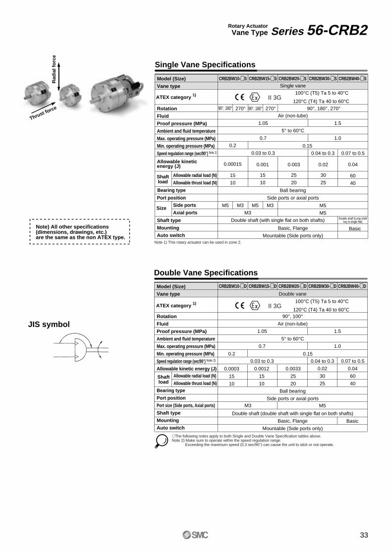
Single Vane Specifications
Double Vane Specifications
Rotary ActuatorVane Type Series 56-CRB2
Model (Size)
Vane type
Rotation
Fluid
Proof pressure (MPa)
Ambient and fluid temperature
Max. operating pressure (MPa)
Min. operating pressure (MPa)
Speed regulation range (sec/90°) Note 2)
Allowable kineticenergy (J)
Port position
Shaft type
Mounting
Auto switch
Allowable radial load (N)
Allowable thrust load (N)
Bearing type
Side ports
Axial ports
CRB2BW10-S CRB2BW15-S CRB2BW20-S CRB2BW30-S CRB2BW40-S
CRB2BW10-D CRB2BW15-D CRB2BW20-D CRB2BW30-D CRB2BW40-D
Single vane
Air (non-lube)
5° to 60°C
Ball bearing
Side ports or axial ports
Basic, Flange
Mountable (Side ports only)
0.2
0.00015
15
10
90°, 180° 270° 90°, 180° 270° 90°, 180°, 270°
1.05
0.7
0.03 to 0.3
1.5
1.0
0.001
15
10
0.003
25
20
0.02
30
25
0.04
60
40
Double shaft (Long shaftkey & single flat)
Basic
M3
M5
M5
0.15
Model (Size)
Vane type
Rotation
Fluid
Proof pressure (MPa)
Ambient and fluid temperature
Max. operating pressure (MPa)
Min. operating pressure (MPa)
Speed regulation range (sec/90°) Note 2)
Allowable kinetic energy (J)
Bearing type
Port position
Port size (Side ports, Axial ports)
Shaft type
Mounting
Auto switch
Allowable radial load (N)
Allowable thrust load (N)
Double vane
90°, 100°Air (non-lube)
5° to 60°C
Ball bearing
Side ports or axial ports
Double shaft (double shaft with single flat on both shafts)
Basic, Flange
Mountable (Side ports only)
0.2
0.0003
15
10
1.05
0.7
0.03 to 0.3
1.5
1.0
0.04 to 0.3
0.02
30
25
0.07 to 0.5
0.04
60
40
0.0012
15
10
0.0033
25
20
0.15
M5 M3 M5 M3
M3 M5
JIS symbol
0.04 to 0.3 0.07 to 0.5
Double shaft (with single flat on both shafts)
Size
∗ The following notes apply to both Single and Double Vane Specification tables above.Note 2) Make sure to operate within the speed regulation range.
Exceeding the maximum speed (0.3 sec/90°) can cause the unit to stick or not operate.
Shaftload
Shaftload
Note) All other specifications (dimensions, drawings, etc.) are the same as the non ATEX type.
ATEX category 1) 100°C (T5) Ta 5 to 40°C
120°C (T4) Ta 40 to 60°CII 3G
ATEX category 1) 100°C (T5) Ta 5 to 40°C
120°C (T4) Ta 40 to 60°CII 3G
Note 1) This rotary actuator can be used in zone 2.
Basic
33
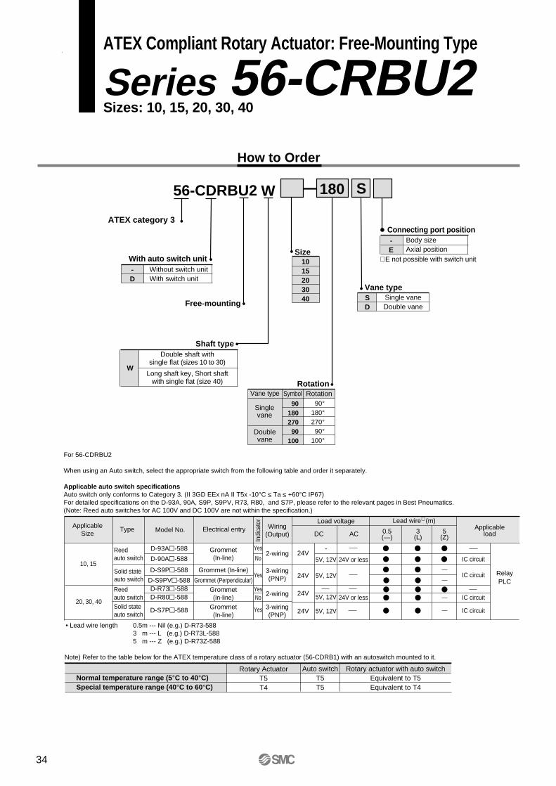
ATEX Compliant Rotary Actuator: Free-Mounting Type
Series 56-CRBU2Sizes: 10, 15, 20, 30, 40
How to Order
W
1015203040
56-CDRBU2 10 180 S
Free-mounting
Shaft type
RotationVane type Symbol Rotation
Singlevane
Doublevane
90180270
90100
90°180°270°
90°100°
With auto switch unit-D
Without switch unitWith switch unit
Vane typeSD
Single vaneDouble vane
W
Double shaft withsingle flat (sizes 10 to 30)
Long shaft key, Short shaftwith single flat (size 40)
Size
ATEX category 3Connecting port position-E
Body sizeAxial position
∗ E not possible with switch unit
Note) Refer to the table below for the ATEX temperature class of a rotary actuator (56-CDRB1) with an autoswitch mounted to it.
Normal temperature range (5°C to 40°C)Special temperature range (40°C to 60°C)
Rotary ActuatorT5T4
Auto switchT5T5
Rotary actuator with auto switchEquivalent to T5Equivalent to T4
Type Model No. Wiring(Output)
Load voltage
Indi
cato
r
Electrical entry ApplicableloadDC AC
Lead wire∗ (m)
0.5(—)
3(L)
5(Z)
Reedauto switch
Solid stateauto switch
D-93A-588
D-90A-588
D-S9P-588
D-S9PV-588D-R73-588D-R80-588
D-S7P-588
Grommet(In-line)
Grommet (In-line)
Grommet (Perpendicular)Grommet(In-line)
Grommet(In-line)
Yes
No
Yes
YesNo
Yes
2-wiring
3-wiring(PNP)
24V
24V
24V
24V
-
5V, 12V
5V, 12V
5V, 12V
5V, 12V
24V or less
24V or less
IC circuit
IC circuit
IC circuit
IC circuit
RelayPLC
For 56-CDRBU2
When using an Auto switch, select the appropriate switch from the following table and order it separately.
Applicable auto switch specificationsAuto switch only conforms to Category 3. (II 3GD EEx nA II T5x -10°C ≤ Ta ≤ +60°C IP67)For detailed specifications on the D-93A, 90A, S9P, S9PV, R73, R80, and S7P, please refer to the relevant pages in Best Pneumatics.(Note: Reed auto switches for AC 100V and DC 100V are not within the specification.)
• Lead wire length 0.5m --- Nil (e.g.) D-R73-5883 m --- L (e.g.) D-R73L-5885 m --- Z (e.g.) D-R73Z-588
Reedauto switchSolid stateauto switch
ApplicableSize
10, 15
20, 30, 402-wiring
3-wiring(PNP)
34
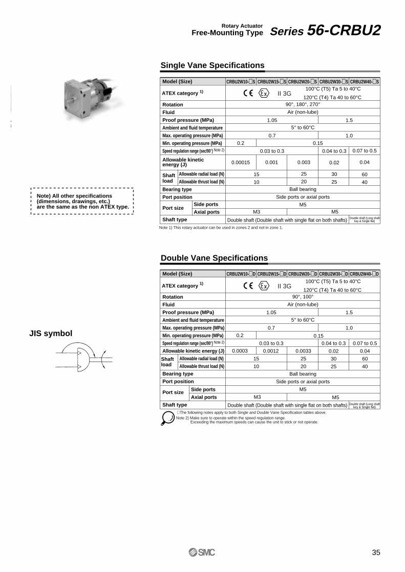
Single Vane Specifications
Double Vane Specifications
Rotary ActuatorFree-Mounting Type Series 56-CRBU2
Model (Size)
Rotation
Fluid
Proof pressure (MPa)
Ambient and fluid temperature
Max. operating pressure (MPa)
Min. operating pressure (MPa)
Speed regulation range (sec/90°) Note 2)
Allowable kineticenergy (J)
Shaftload
Bearing type
Port position
Port size
Shaft type
Allowable radial load (N)
Allowable thrust load (N)
CRBU2W10-S CRBU2W15-S CRBU2W20-S CRBU2W30-S CRBU2W40-S
CRBU2W10-D CRBU2W15-D CRBU2W20-D CRBU2W30-D CRBU2W40-D
90°, 180°, 270°Air (non-lube)
5° to 60°C
Ball bearing
Side ports or axial ports
M5
0.2
0.00015
1.05
0.7
0.03 to 0.3
1.5
1.0
0.001 0.003
25
20
0.04 to 0.3
0.02
30
25
0.07 to 0.5
0.04
60
40
Double shaft (Long shaftkey & Single flat)Double shaft (Double shaft with single flat on both shafts)
0.15
Model (Size)
Rotation
Fluid
Proof pressure (MPa)
Ambient and fluid temperature
Max. operating pressure (MPa)
Min. operating pressure (MPa)
Speed regulation range (sec/90°) Note 2)
Allowable kinetic energy (J)
Shaftload
Bearing type
Port position
Port size
Shaft type
Allowable radial load (N)
Allowable thrust load (N)
90°, 100°Air (non-lube)
5° to 60°C
Ball bearing
Side ports or axial ports
M5
0.2
0.0003
15
10
1.05
0.7
0.03 to 0.3
1.5
1.0
0.04 to 0.3
0.02
30
25
0.07 to 0.5
0.04
60
40
0.0012 0.0033
25
20
0.15JIS symbol
Double shaft (Double shaft with single flat on both shafts) Double shaft (Long shaftkey & Single flat)
15
10
∗ The following notes apply to both Single and Double Vane Specification tables above.Note 2) Make sure to operate within the speed regulation range.
Exceeding the maximum speeds can cause the unit to stick or not operate.
Note) All other specifications (dimensions, drawings, etc.) are the same as the non ATEX type.
ATEX category 1) 100°C (T5) Ta 5 to 40°C
120°C (T4) Ta 40 to 60°CII 3G
ATEX category 1) 100°C (T5) Ta 5 to 40°C
120°C (T4) Ta 40 to 60°CII 3G
Rad
ial f
orc
e
Thrust force
Note 1) This rotary actuator can be used in zones 2 and not in zone 1.
Side ports
Axial ports M5M3
M3 M5
Side ports
Axial ports
35
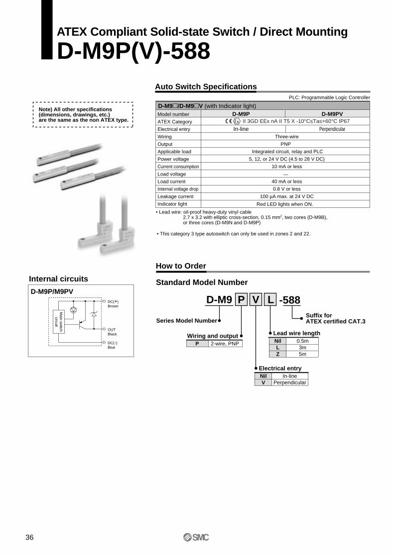
Three-wire
Integrated circuit, relay and PLC
5, 12, or 24 V DC (4.5 to 28 V DC)
10 mA or less
40 mA or less
0.8 V or less
100 µA max. at 24 V DC
Internal circuits
D-M9P/M9PV
Auto Switch Specifications
How to Order
PLC: Programmable Logic Controller
Model number
ATEX Category
Electrical entry
Wiring
Output
Applicable load
Power voltage
Current consumption
Load voltage
Load current
Internal voltage drop
Leakage current
Indicator light Red LED lights when ON.
Standard Model Number
PNP
—
Main sw
itchcircuit
DC(+)Brown
OUTBlack
DC(-)Blue
D-M9/D-M9V (with Indicator light)
• Lead wire: oil-proof heavy-duty vinyl cable2.7 x 3.2 with elliptic cross-section, 0.15 mm2, two cores (D-M9B), or three cores (D-M9N and D-M9P)
D-M9P
In-line
D-M9PV
Perpendicular
Series Model Number
NilLZ
0.5m3m5m
Lead wire length
NilV
In-linePerpendicular
P 2-wire, PNPWiring and output
D-M9 P L
Electrical entry
V -588
Note) All other specifications (dimensions, drawings, etc.) are the same as the non ATEX type.
• This category 3 type autoswitch can only be used in zones 2 and 22.
II 3GD EEx nA II T5 X -10°C≤Ta≤+60°C IP67
Suffix forATEX certified CAT.3
36
ATEX Compliant Solid-state Switch / Direct Mounting
D-M9P(V)-588
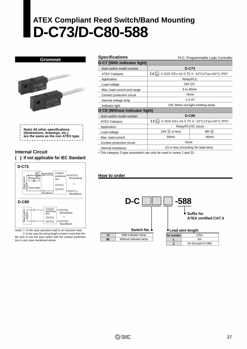
Specifications PLC: Programmable Logic Controller
D-C7 (With indicator light) Auto switch model number
ATEX Category
Application
Load voltage
Max. load current and range
Contact protection circuit
Internal voltage drop
Indicator light
D-C8 (Without indicator light) Auto switch model number
ATEX Category
Application
Load voltage
Max. load current
Contact protection circuit
Internal resistance
D-C73
Relay/PLC
24V DC
5 to 40mA
None
ON: When red light emitting diode
D-C80
Relay/PLC/IC circuit
24V or less
50mA
48V
40mA
None
1Ω or less (Including 3m lead wire)
ACDC
ACDC
How to order
≤ 2.4V
Note) All other specifications (dimensions, drawings, etc.) are the same as the non ATEX type.
D-CSuffix for ATEX certified CAT.3
No numberLZ
0.5m3m
5m (Except D-C80)
Lead wire length
-588
7380
With indicator lampWithout indicator lamp
Switch No.
II 3GD EEx nA II T5 X -10°C≤Ta≤+60°C IP67
II 3GD EEx nA II T5 X -10°C≤Ta≤+60°C IP67
• This category 3 type autoswitch can only be used in zones 2 and 22.
37
ATEX Compliant Reed Switch/Band Mounting
D-C73/D-C80-588
Grommet
Internal Circuit( ): If not applicable for IEC Standard
Note) q In the case operation load is an inductive load. w In the case the wiring length to load is more than 5m.
Be sure to use the auto switch with the contact protectionbox in any case mentioned above.
D-C73
D-C80
LED
Ree
d sw
itch Resistance
Zener diode
Contactprotectivebox
CD-P11
CD-P12
Brown(Red)
Blue(Black)
OUT(+)Brown(Red)
OUT(–)Blue(Black)
Ree
d sw
itch Contact
protectivebox
CD-P11
CD-P12
OUT(±)Brown(Red)
OUT( )Blue(Black)
±
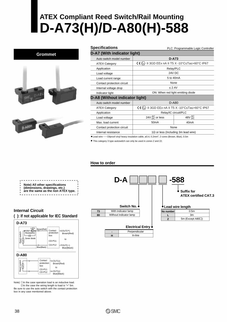
Specifications
How to order
D-A7 (With indicator light)PLC: Programmable Logic Controller
Auto switch model number
ATEX Category
Application
Load voltage
Load current range
Contact protection circuit
Internal voltage drop
Indicator light
24V DC
5 to 40mA
None
≤ 2.4V
ON: When red light emitting diode
D-A73
Relay/PLC
D-A80
Relay/IC circuit/PLC
40mA
None
1Ω or less (Including 3m lead wire)
D-A8 (Without indicator light)Auto switch model number
ATEX Category
Application
Load voltage
Max. load current
Contact protection circuit
Internal resistance
Lead wire Oilproof vinyl heavy insulation cable, ø3.4, 0.2mm2, 2 cores (Brown, Blue), 0.5m
50mA
24V or lessACDC 48V AC
DC
Note) All other specifications (dimensions, drawings, etc.) are the same as the non ATEX type.
D-ASuffix for ATEX certified CAT.3
No numberLZ
0.5m3m
5m (Except A80)
Lead wire length
-588
7380
With indicator lampWithout indicator lamp
Switch No.
This category 3 type autoswitch can only be used in zones 2 and 22.
II 3GD EEx nA II T5 X -10°C≤Ta≤+60°C IP67
II 3GD EEx nA II T5 X -10°C≤Ta≤+60°C IP67
-H
PerpendicularIn-line
Electrical Entry
38
ATEX Compliant Reed Switch/Rail Mounting
D-A73(H)/D-A80(H)-588
Grommet
D-A73
D-A80
Note) qIn the case operation load is an inductive load. wIn the case the wiring length to load is “>” 5m.
Be sure to use the auto switch with the contact protectionbox in any case mentioned above.
LED
Ree
d sw
itch Resistance
Zener diode
Contactprotectionbox
CD-P11
CD-P12
Brown(Red)
Blue(Black)
OUT(+)Brown(Red)
to
OUT(–)Blue(Black)
Ree
d sw
itch Contact
protectionbox
CD-P11CD-P12
OUT(±)Brown(Red)
to
OUT( )Blue(Black)
±
Internal Circuit( ): If not applicable for IEC Standard
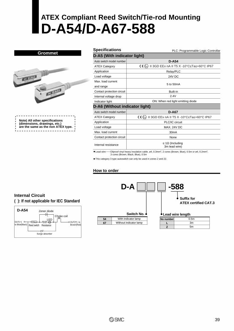
Specifications
How to order
D-A5 (With indicator light)PLC: Programmable Logic Controllar
Auto switch model number
ATEX Category
Application
Load voltage
Max. load current
and range
Contact protection circuit
Internal voltage drop
Indicator light
D-A54
Relay/PLC
24V DC
5 to 50mA
Built-in
D-A6 (Without indicator light)Auto switch model number
ATEX Category
Application
Load voltage
Max. load current
Contact protection circuit
Internal resistance
D-A67
PLC/IC circuit
MAX. 24V DC
30mA
None
≤ 1Ω (Including 3m lead wire)
Lead wire Oilproof vinyl heavy insulation cable, ø4, 0.3mm2, 2 cores (Brown, Blue), 0.5m or ø4, 0.2mm2, 3 cores (Brown, Black, Blue), 0.5m
2.4V
ON: When red light emitting diode
Note) All other specifications (dimensions, drawings, etc.) are the same as the non ATEX type.
D-ASuffix for ATEX certified CAT.3
No numberLZ
0.5m3m5m
Lead wire length
-588
5467
With indicator lampWithout indicator lamp
Switch No.
This category 3 type autoswitch can only be used in zones 2 and 22.
II 3GD EEx nA II T5 X -10°C≤Ta≤+60°C IP67
II 3GD EEx nA II T5 X -10°C≤Ta≤+60°C IP67
39
ATEX Compliant Reed Switch/Tie-rod Mounting
D-A54/D-A67-588
Grommet
D-A54 Zener diode
Reed switch
LED
Resistance
Choke coil
Surge absorber
OUT(–) to Blue(Black)
OUT(+) toBrown(Red)
Internal Circuit( ): If not applicable for IEC Standard
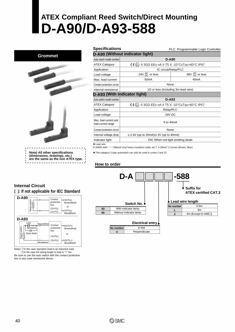
Specifications PLC: Programmable Logic Controller
D-A90 (Without indicator light)Auto swich modle number
ATEX Category
Application
Load voltage
Max. load current
Contact protection circuit
Internal resistance
D-A93 (With indicator light)Auto switch model number
ATEX Category
Application
Load voltage
Contact protection circuit
Internal voltage drop
Indicator light
How to order
Lead wire D-A90/D-A93 Oilproof vinyl heavy insulation cable, ø2.7, 0.18mm2 X 2cores (Brown, Blue)
D-A90
IC circuit/Relay/PLC
24V or less
50mA
None
1Ω or less (Including 3m lead wire)
48V or less
40mA
D-A93
Relay/PLC
24V DC
5 to 40mA
None
≤ 2.4V (up to 20mA)/≤ 3V (up to 40mA)
ON: When red light emitting diode
ACDC
ACDC
Max. load current and load current range
Note) All other specifications (dimensions, drawings, etc.) are the same as the non ATEX type.
This category 3 type autoswitch can only be used in zones 2 and 22.
D-ASuffix for ATEX certified CAT.3
No numberLZ
0.5m3m
5m (Except D-A90)
Lead wire length
-588
9390
With indicator lampWithout indicator lamp
Switch No.
No numberV
In linePerpendicular
Electrical entry
II 3GD EEx nA II T5 X -10°C≤Ta≤+60°C IP67
II 3GD EEx nA II T5 X -10°C≤Ta≤+60°C IP67
40
ATEX Compliant Reed Switch/Direct Mounting
D-A90/D-A93-588
Grommet
Note) qIn the case operation load is an inductive load.wIn the case the wiring length to load is “>” 5m.
Be sure to use the auto switch with the contact protectionbox in any case mentioned above.
D-A90
D-A93
Ree
d sw
itch Contact
protectivebox
CD-P11CD-P12
OUT(±)Brown(Red)
to
OUT( )Blue(Black)
±
Blue(Black)
LED
Ree
d sw
itch Resistance
Zener diode
Brown(Red) Contact protectivebox
CD-P11
CD-P12
OUT(+)Brown(Red)
to
OUT(–)Blue(Black)
Internal Circuit( ): If not applicable for IEC Standard
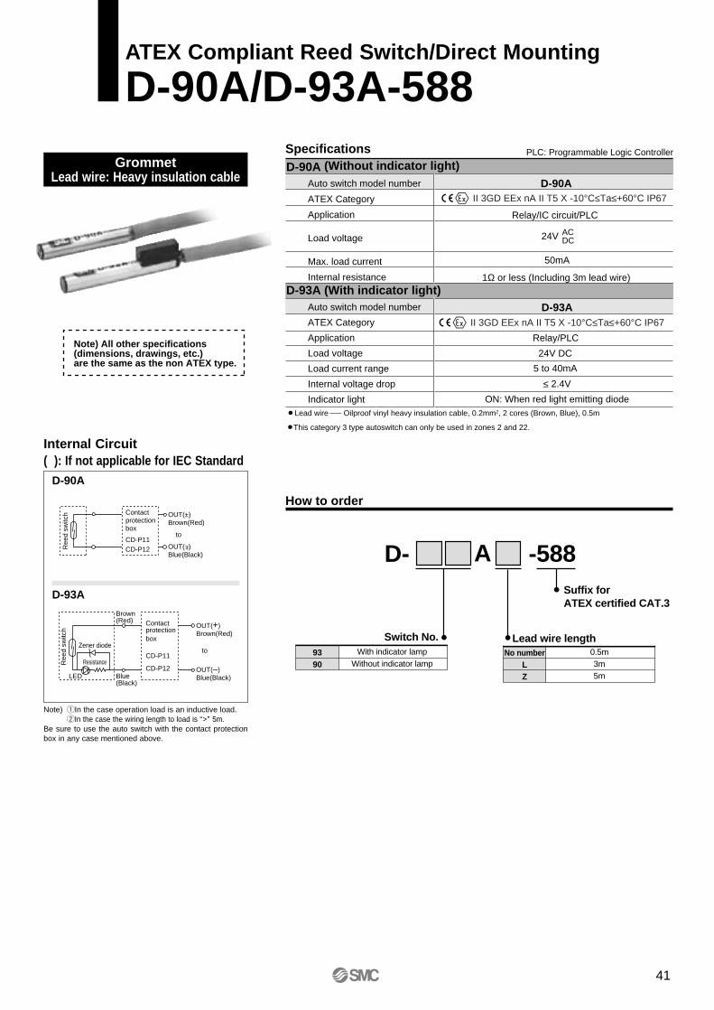
Specifications PLC: Programmable Logic Controller
D-90A (Without indicator light)
Auto switch model number
ATEX Category
Application
Load voltage
Load current range
Internal voltage drop
Indicator light
D-93A (With indicator light)
Auto switch model number
ATEX Category
Application
Load voltage
Max. load current
Internal resistance
Lead wire Oilproof vinyl heavy insulation cable, 0.2mm2, 2 cores (Brown, Blue), 0.5m
D-93A
Relay/PLC
≤ 2.4V
ON: When red light emitting diode
D-90A
Relay/IC circuit/PLC
1Ω or less (Including 3m lead wire)
50mA
24V DC
5 to 40mA
ACDC24V
Note) All other specifications (dimensions, drawings, etc.) are the same as the non ATEX type.
How to order
D-Suffix for ATEX certified CAT.3
No numberLZ
0.5m3m5m
Lead wire length
-588
9390
With indicator lampWithout indicator lamp
Switch No.
This category 3 type autoswitch can only be used in zones 2 and 22.
A
II 3GD EEx nA II T5 X -10°C≤Ta≤+60°C IP67
II 3GD EEx nA II T5 X -10°C≤Ta≤+60°C IP67
41
ATEX Compliant Reed Switch/Direct Mounting
D-90A/D-93A-588
D-90A
D-93A
Ree
d sw
itch Contact
protectionbox
CD-P11CD-P12
OUT(±)Brown(Red)
to
OUT( )Blue(Black)
±
LED
Ree
d sw
itch
Resistance
Zener diode
Contact protectionbox
CD-P11
CD-P12
Brown(Red)
Blue(Black)
OUT(+)Brown(Red)
to
OUT(–)Blue(Black)
Grommet Lead wire: Heavy insulation cable
Internal Circuit( ): If not applicable for IEC Standard
Note) qIn the case operation load is an inductive load. wIn the case the wiring length to load is “>” 5m.
Be sure to use the auto switch with the contact protectionbox in any case mentioned above.
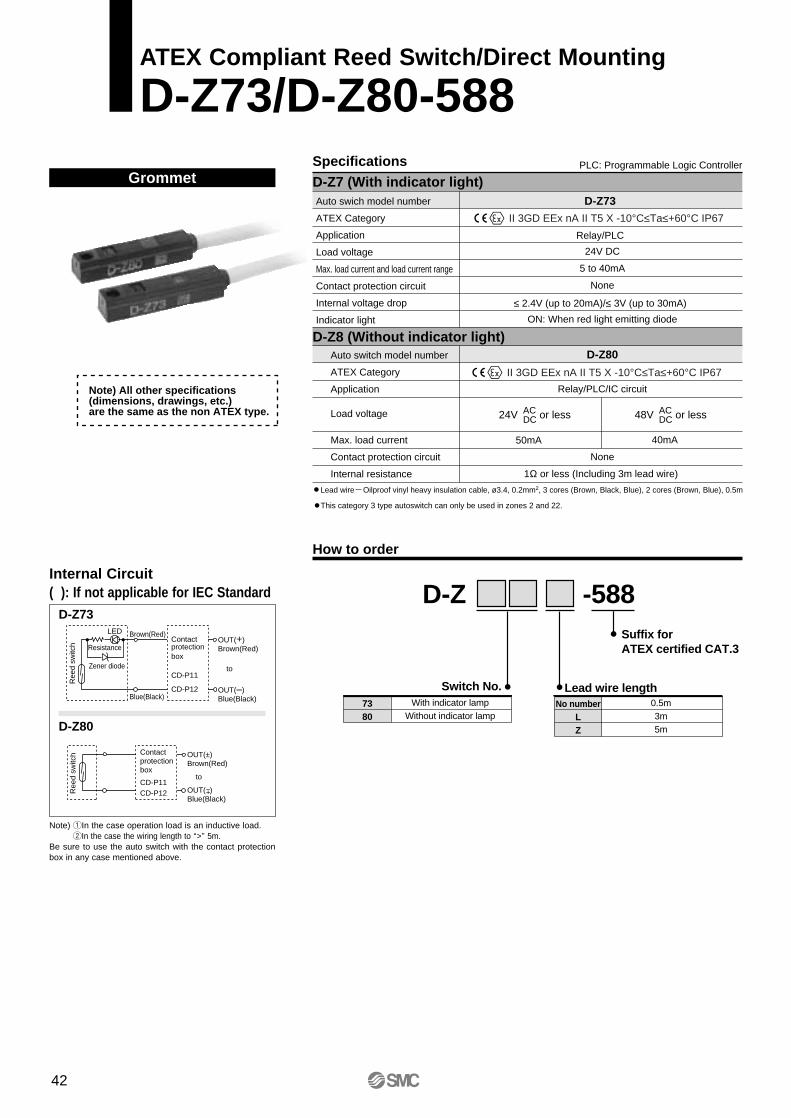
Specifications
How to order
D-Z7 (With indicator light)PLC: Programmable Logic Controller
Auto swich model number
ATEX Category
Application
Load voltage
Max. load current and load current range
Contact protection circuit
Internal voltage drop
Indicator light
D-Z73
Relay/PLC
≤ 2.4V (up to 20mA)/≤ 3V (up to 30mA)
24V DC
5 to 40mA
None
ON: When red light emitting diode
D-Z80
Relay/PLC/IC circuit
40mA
None
1Ω or less (Including 3m lead wire)
D-Z8 (Without indicator light)Auto switch model number
ATEX Category
Application
Max. load current
Contact protection circuit
Internal resistance
Lead wire Oilproof vinyl heavy insulation cable, ø3.4, 0.2mm2, 3 cores (Brown, Black, Blue), 2 cores (Brown, Blue), 0.5m
50mA
ACDC24V or less AC
DC48V or lessLoad voltage
Note) All other specifications (dimensions, drawings, etc.) are the same as the non ATEX type.
D-ZSuffix for ATEX certified CAT.3
No numberLZ
0.5m3m5m
Lead wire length
-588
7380
With indicator lampWithout indicator lamp
Switch No.
This category 3 type autoswitch can only be used in zones 2 and 22.
II 3GD EEx nA II T5 X -10°C≤Ta≤+60°C IP67
II 3GD EEx nA II T5 X -10°C≤Ta≤+60°C IP67
42
ATEX Compliant Reed Switch/Direct Mounting
D-Z73/D-Z80-588
D-Z73
D-Z80
LED
Ree
d sw
itch Resistance
Zener diode
Contact protectionbox
CD-P11
CD-P12
Brown(Red)
Blue(Black)
OUT(+)Brown(Red)
to
OUT(–)Blue(Black)
Ree
d sw
itch Contact
protectionbox
CD-P11CD-P12
OUT(±)Brown(Red)
to
OUT( )Blue(Black)
±
Grommet
Internal Circuit( ): If not applicable for IEC Standard
Note) qIn the case operation load is an inductive load. wIn the case the wiring length to “>” 5m.
Be sure to use the auto switch with the contact protectionbox in any case mentioned above.
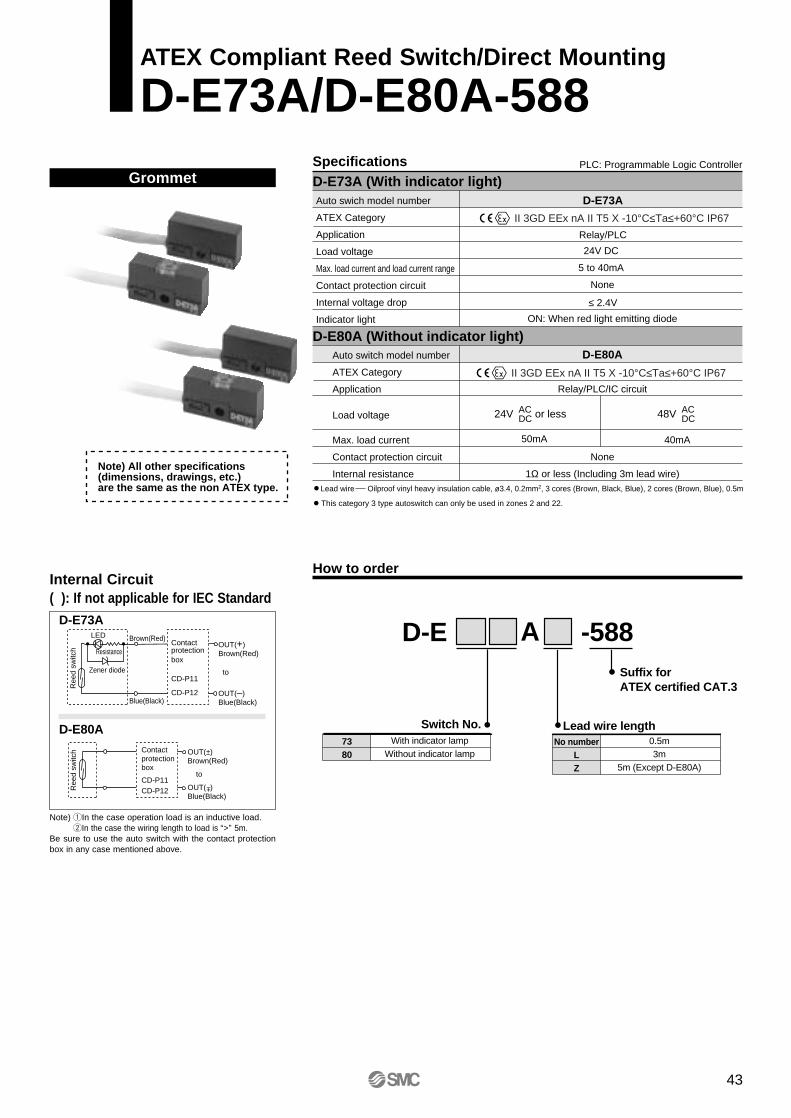
Specifications
How to order
D-E73A (With indicator light)PLC: Programmable Logic Controller
Auto swich model number
ATEX Category
Application
Load voltage
Max. load current and load current range
Contact protection circuit
Internal voltage drop
Indicator light
D-E73A
Relay/PLC
≤ 2.4V
24V DC
5 to 40mA
None
ON: When red light emitting diode
D-E80A
Relay/PLC/IC circuit
40mA
None
1Ω or less (Including 3m lead wire)
D-E80A (Without indicator light)Auto switch model number
ATEX Category
Application
Load voltage
Max. load current
Contact protection circuit
Internal resistance
50mA
ACDC24V or less AC
DC48V
Lead wire Oilproof vinyl heavy insulation cable, ø3.4, 0.2mm2, 3 cores (Brown, Black, Blue), 2 cores (Brown, Blue), 0.5m
Note) All other specifications (dimensions, drawings, etc.) are the same as the non ATEX type.
D-ESuffix for ATEX certified CAT.3
No numberLZ
0.5m3m
5m (Except D-E80A)
Lead wire length
-588
7380
With indicator lampWithout indicator lamp
Switch No.
A
This category 3 type autoswitch can only be used in zones 2 and 22.
II 3GD EEx nA II T5 X -10°C≤Ta≤+60°C IP67
II 3GD EEx nA II T5 X -10°C≤Ta≤+60°C IP67
43
ATEX Compliant Reed Switch/Direct Mounting
D-E73A/D-E80A-588
D-E73A
D-E80A
Blue(Black)
LED
Ree
d sw
itch Resistance
Zener diode
Brown(Red) Contact protectionbox
CD-P11
CD-P12
OUT(+)Brown(Red)
to
OUT(–)Blue(Black)
Ree
d sw
itch Contact
protectionbox
CD-P11CD-P12
OUT(±)Brown(Red)
to
OUT( )Blue(Black)
±
Grommet
Internal Circuit( ): If not applicable for IEC Standard
Note) qIn the case operation load is an inductive load. wIn the case the wiring length to load is “>” 5m.
Be sure to use the auto switch with the contact protectionbox in any case mentioned above.
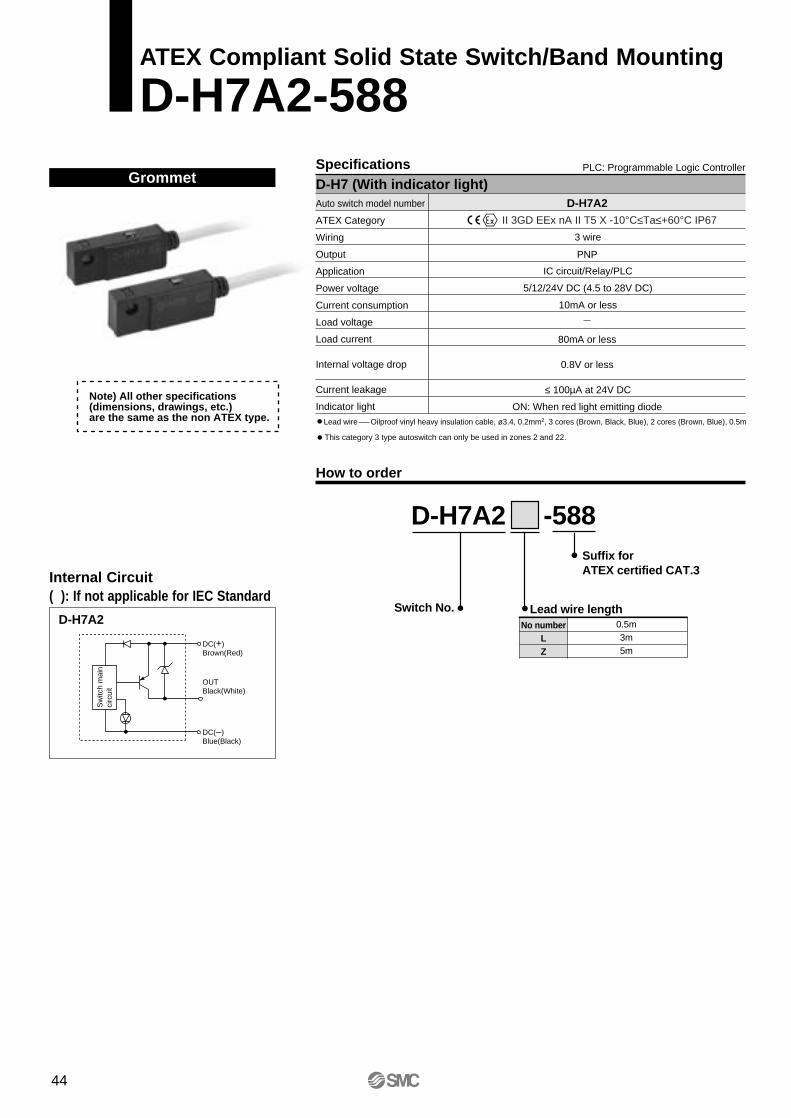
Specifications
How to order
D-H7 (With indicator light)PLC: Programmable Logic Controller
Auto switch model number
ATEX Category
Wiring
Output
Application
Power voltage
Current consumption
Load voltage
Load current
Internal voltage drop
Current leakage
Indicator light
D-H7A2
PNP
80mA or less
0.8V or less
ON: When red light emitting diode
3 wire
IC circuit/Relay/PLC
5/12/24V DC (4.5 to 28V DC)
10mA or less
≤ 100µA at 24V DC
Lead wire Oilproof vinyl heavy insulation cable, ø3.4, 0.2mm2, 3 cores (Brown, Black, Blue), 2 cores (Brown, Blue), 0.5m
This category 3 type autoswitch can only be used in zones 2 and 22.
Note) All other specifications (dimensions, drawings, etc.) are the same as the non ATEX type.
II 3GD EEx nA II T5 X -10°C≤Ta≤+60°C IP67
D-H7A2Suffix for ATEX certified CAT.3
No numberLZ
0.5m3m5m
Lead wire length
-588
Switch No.
44
ATEX Compliant Solid State Switch/Band Mounting
D-H7A2-588
D-H7A2
OUTBlack(White)
DC(+)Brown(Red)
DC(–)Blue(Black)
Sw
itch
mai
n ci
rcui
t
Grommet
Internal Circuit( ): If not applicable for IEC Standard

Specifications
How to order
D-F7P (With indicator light)PLC: Programmable Logic Controller
Auto switch model number
ATEX Category
Wiring
Output
Application
Power voltage
Current consumption
Load voltage
Load current
Internal voltage drop
Current leakage
Indicator light
D-F7P
PNP
80mA or less
0.8V or less
ON: When red light emitting diode
3 wire
IC circuit/Relay/PLC
5/12/24V DC (4.5 to 28V DC)
≤ 10mA
≤ 100µA at 24V DC
Lead wire Oilproof vinyl heavy insulation cable, ø3.4, 0.2mm2, 3 cores (Brown, Black, Blue), 2 cores (Brown, Blue), 0.5m
Note) All other specifications (dimensions, drawings, etc.) are the same as the non ATEX type. D-F7P
Suffix for ATEX certified CAT.3
No numberLZ
0.5m3m5m
Lead wire length
-588
No numberV
Right armPerpendicular
Switch No.
Electrical entry
This category 3 type autoswitch can only be used in zones 2 and 22.
II 3GD EEx nA II T5 X -10°C≤Ta≤+60°C IP67
45
ATEX Compliant Solid State Switch/Rail Mounting
D-F7P-588
D-F7P
OUTBlack(White)
DC(+)Brown(Red)
DC(–)Blue(Black)
Sw
itch
mai
n ci
rcui
t
Grommet
Internal Circuit( ): If not applicable for IEC Standard
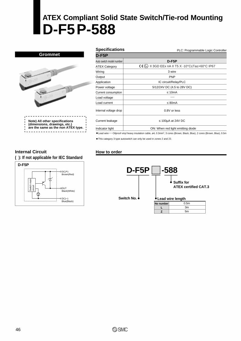
3 wire
IC circuit/Relay/PLC
5/12/24V DC (4.5 to 28V DC)
≤ 10mA
≤ 100µA at 24V DC
How to order
SpecificationsD-F5P
PLC: Programmable Logic Controller
Auto switch model number
ATEX Category
Wiring
Output
Application
Power voltage
Current consumption
Load voltage
Load current
Internal voltage drop
Current leakage
Indicator light
D-F5P
PNP
≤ 80mA
0.8V or less
ON: When red light emitting diode
Lead wire Oilproof vinyl heavy insulation cable, ø4, 0.3mm2, 3 cores (Brown, Black, Blue), 2 cores (Brown, Blue), 0.5m
Note) All other specifications (dimensions, drawings, etc.) are the same as the non ATEX type.
This category 3 type autoswitch can only be used in zones 2 and 22.
D-F5PSuffix for ATEX certified CAT.3
No numberLZ
0.5m3m5m
Lead wire length
-588
Switch No.
II 3GD EEx nA II T5 X -10°C≤Ta≤+60°C IP67
46
ATEX Compliant Solid State Switch/Tie-rod Mounting
D-F5P-588
D-F5P
OUTBlack(White)
DC(+)Brown(Red)
DC(–)Blue(Black)
Sw
itch
mai
n ci
rcui
t
Grommet
Internal Circuit( ): If not applicable for IEC Standard
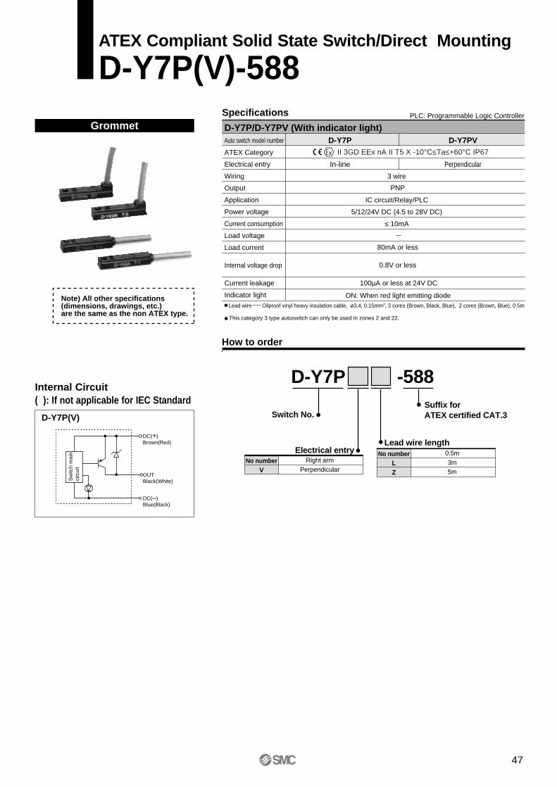
How to order
Specifications PLC: Programmable Logic Controller
D-Y7P/D-Y7PV (With indicator light)Auto switch model number
ATEX Category
Electrical entry
Wiring
Output
Application
Power voltage
Current consumption
Load voltage
Load current
Internal voltage drop
Current leakage
Indicator light
D-Y7PV
Perpendicular
D-Y7P
In-line
3 wire
IC circuit/Relay/PLC
5/12/24V DC (4.5 to 28V DC)
≤ 10mA
PNP
80mA or less
0.8V or less
ON: When red light emitting diode
100µA or less at 24V DC
Lead wire Oilproof vinyl heavy insulation cable, ø3.4, 0.15mm2, 3 cores (Brown, Black, Blue), 2 cores (Brown, Blue), 0.5mNote) All other specifications (dimensions, drawings, etc.) are the same as the non ATEX type.
D-Y7PSuffix for ATEX certified CAT.3
No numberLZ
0.5m3m5m
Lead wire length
-588
No numberV
Right armPerpendicular
Switch No.
Electrical entry
This category 3 type autoswitch can only be used in zones 2 and 22.
II 3GD EEx nA II T5 X -10°C≤Ta≤+60°C IP67
47
ATEX Compliant Solid State Switch/Direct Mounting
D-Y7P(V)-588
D-Y7P(V)
OUTBlack(White)
DC(+)Brown(Red)
DC(–)Blue(Black)
Sw
itch
mai
n ci
rcui
t
Grommet
Internal Circuit( ): If not applicable for IEC Standard
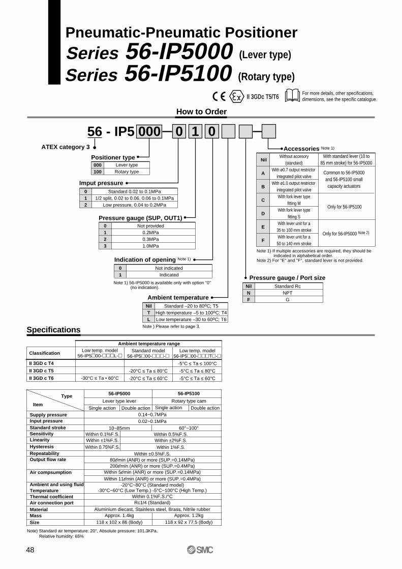
For more details, other specifications, dimensions, see the specific catalogue.
Pneumatic-Pneumatic PositionerSeries 56-IP5000 (Lever type)
56 - IP5 000ATEX category 3
How to Order
Series 56-IP5100 (Rotary type)
Positioner type000100
Lever typeRotary type
Pressure gauge (SUP, OUT1)0123
Not provided0.2MPa0.3MPa1.0MPa
Nil
A
B
C
D
E
F
Without accesory(standard)
With ø0.7 output restrictor integrated pilot valve
With ø1.0 output restrictor integrated pilot valveWith fork lever type
fitting MWith fork lever type
fitting SWith lever unit for a35 to 100 mm strokeWith lever unit for a50 to 140 mm stroke
With standard lever (10 to85 mm stroke) for 56-IP5000
Accessories Note 1)
Note 1) If multiple accessories are required, they should be indicated in alphabetical order.
Note 2) For ''E'' and ''F'', standard lever is not provided.
10 0
Imput pressure012
Standard 0.02 to 0.1MPa1/2 split, 0.02 to 0.06, 0.06 to 0.1MPa
Low pressure, 0.04 to 0.2MPa
Indication of opening Note 1)
01
Not indicatedIndicated
Note 1) 56-IP5000 is available only with option ''0'' (no indication).
Ambient temperatureNilTL
Standard –20 to 80oC; T5High temperature –5 to 100oC; T4Low temperature –30 to 60oC; T6
Pressure gauge / Port sizeNilNF
Standard RcNPT
G
Common to 56-IP5000and 56-IP5100 smallcapacity actuators
Only for 56-IP5100
Only for 56-IP5000 Note 2)
II 3GDc T5/T6
Note ) Please refer to page 3.Specifications
Classification
II 3GD c T4
II 3GD c T5
II 3GD c T6
Low temp. model56-IP500-L-
-30°C ≤ Ta • 60°C
Standard model56-IP500--
-20°C ≤ Ta ≤ 80°C-20°C ≤ Ta ≤ 60°C
Low temp. model56-IP500-T-
-5°C ≤ Ta ≤ 100°C-5°C ≤ Ta ≤ 80°C-5°C ≤ Ta ≤ 60°C
Ambient temperature range
Type
Item
Supply pressureInput pressureStandard strokeSensitivityLinearityHysteresisRepeatabilityOutput flow rate
Air compsumption
Ambient and using fluidTemperatureThermal coefficientAir connection portMaterialMassSize
56-IP5000
Lever type lever
10~85mm
Approx. 1.4kg118 x 102 x 86 (Body)
56-IP5100
Rotary type cam
60°~100°
Approx. 1.2kg118 x 92 x 77.5 (Body)
Single action Double action Single action Double action
Within 0.1%F.S.Within ±1%F.S.Within 0.75%F.S.
Within 0.5%F.S.Within ±2%F.S.Within 1%F.S.
0.14~0.7MPa0.02~0.1MPa
Within ±0.5%F.S.80l/min (ANR) or more (SUP.=0.14MPa)200l/min (ANR) or more (SUP.=0.4MPa)
Within 5l/min (ANR) or more (SUP.=0.14MPa)Within 11l/min (ANR) or more (SUP.=0.4MPa)
-20°C~80°C (Standard model)-30°C~60°C (Low Temp.) -5°C~100°C (High Temp.)
Within 0.1%F.S./°CRc1/4 (Standard)
Aluminium diecast, Stainless steel, Brass, Nitrile rubber
Note) Standard air temperature: 20°, Absolute pressure: 101.3KPa. Relative humidity: 65%
48
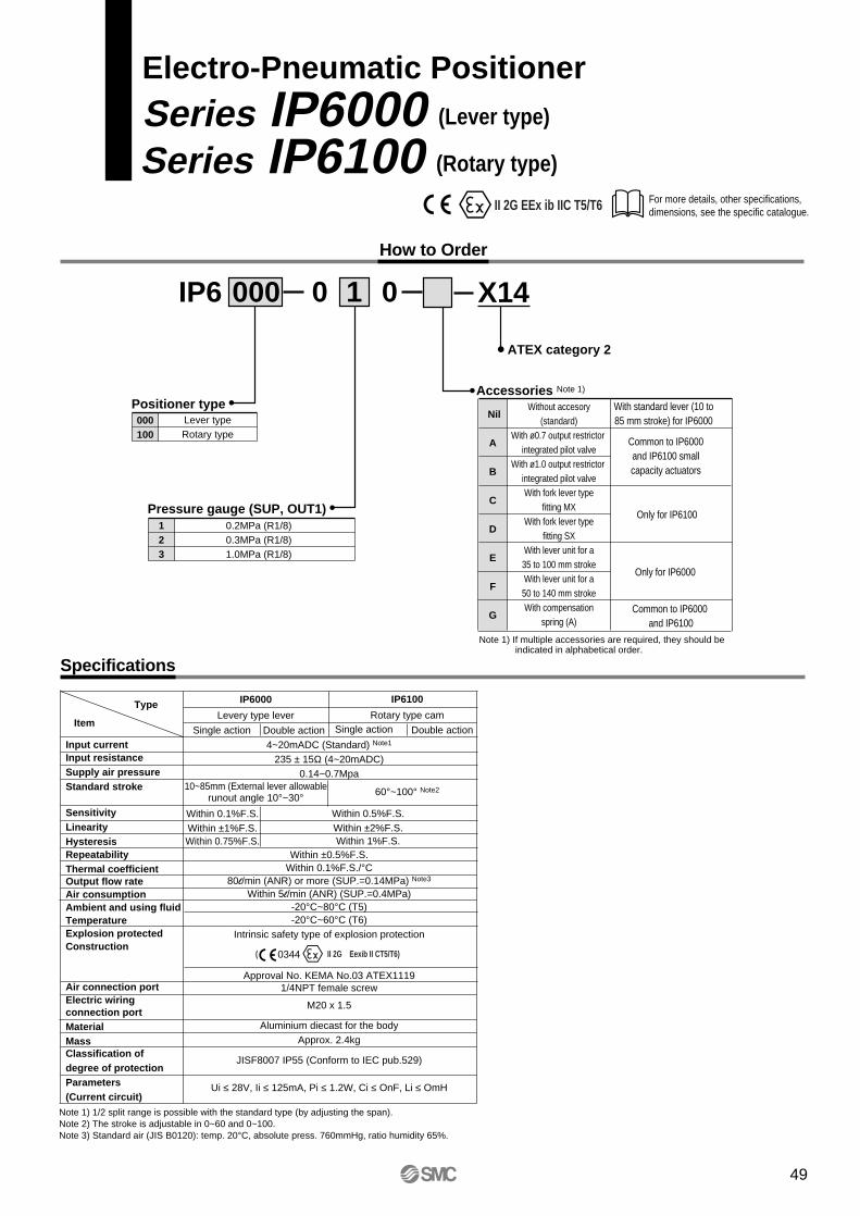
4~20mADC (Standard) Note1
235 ± 15Ω (4~20mADC)0.14~0.7Mpa
Within ±0.5%F.S.Within 0.1%F.S./°C
80l/min (ANR) or more (SUP.=0.14MPa) Note3
Within 5l/min (ANR) (SUP.=0.4MPa)-20°C~80°C (T5)-20°C~60°C (T6)
Intrinsic safety type of explosion protection
Approval No. KEMA No.03 ATEX11191/4NPT female screw
M20 x 1.5
Aluminium diecast for the bodyApprox. 2.4kg
JISF8007 IP55 (Conform to IEC pub.529)
Ui ≤ 28V, Ii ≤ 125mA, Pi ≤ 1.2W, Ci ≤ OnF, Li ≤ OmH
For more details, other specifications, dimensions, see the specific catalogue.
Electro-Pneumatic Positioner
Series IP6000 (Lever type)
IP6 000
ATEX category 2
How to Order
Series IP6100 (Rotary type)
Positioner type000100
Lever typeRotary type
Pressure gauge (SUP, OUT1)123
0.2MPa (R1/8)0.3MPa (R1/8)1.0MPa (R1/8)
Nil
A
B
C
D
E
F
G
Without accesory(standard)
With ø0.7 output restrictor integrated pilot valve
With ø1.0 output restrictor integrated pilot valveWith fork lever type
fitting MXWith fork lever type
fitting SXWith lever unit for a35 to 100 mm strokeWith lever unit for a50 to 140 mm strokeWith compensation
spring (A)
With standard lever (10 to85 mm stroke) for IP6000
Accessories Note 1)
Note 1) If multiple accessories are required, they should be indicated in alphabetical order.
10 0
Common to IP6000and IP6100 smallcapacity actuators
Only for IP6100
Only for IP6000
X14
Common to IP6000 and IP6100
II 2G EEx ib IIC T5/T6
Specifications
Type
Item
Input currentInput resistanceSupply air pressureStandard stroke
SensitivityLinearityHysteresisRepeatabilityThermal coefficientOutput flow rateAir consumptionAmbient and using fluidTemperatureExplosion protectedConstruction
Air connection portElectric wiringconnection portMaterialMassClassification ofdegree of protectionParameters(Current circuit)
IP6000
Levery type lever
10~85mm (External lever allowablerunout angle 10°~30°
IP6100
Rotary type cam
60°~100° Note2
Single action Double action Single action Double action
Within 0.1%F.S.Within ±1%F.S.Within 0.75%F.S.
Note 1) 1/2 split range is possible with the standard type (by adjusting the span).Note 2) The stroke is adjustable in 0~60 and 0~100.Note 3) Standard air (JIS B0120): temp. 20°C, absolute press. 760mmHg, ratio humidity 65%.
( II 2G Eexib II CT5/T6)
Within 0.5%F.S.Within ±2%F.S.Within 1%F.S.
0344
49
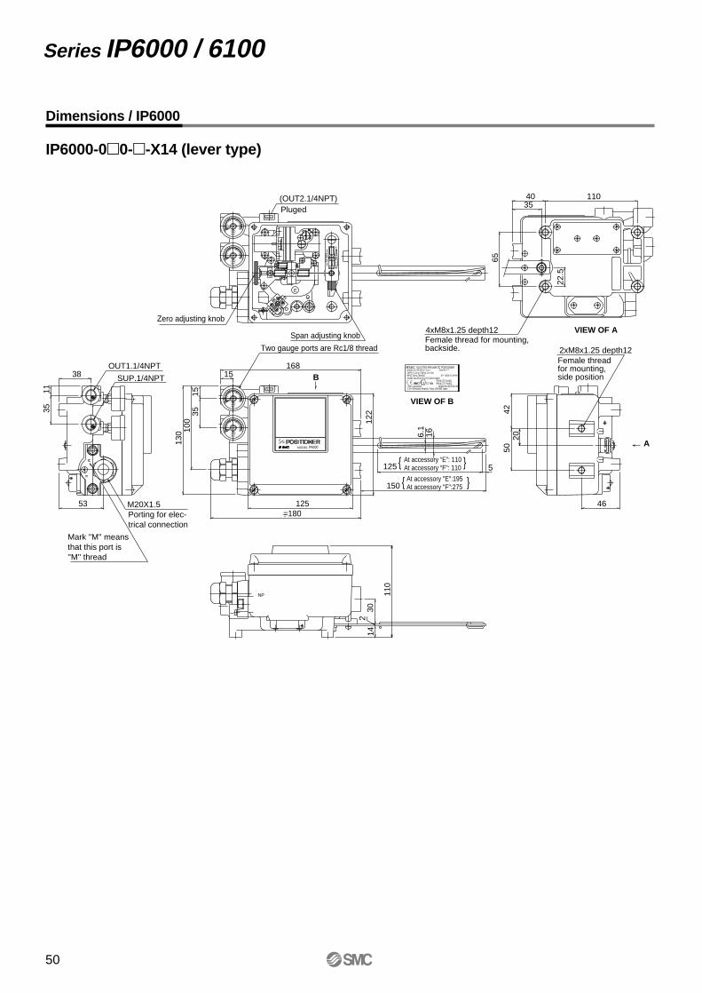
Series IP6000 / 6100
Dimensions / IP6000
IP6000-00--X14 (lever type)
MPabar
SMC
MPabar
SMC
Zero adjusting knob
SMC Corporation 1-16-4 Shinbashi Minatoku Tokyo 105-8659 Japan
KEMA No.03ATEX1119EExIb CT5 Ta≤80CEExIb CT6 Ta≤60C
UI≤28V II≤125mA P≤1.2V CI≤0nf LI≤0nH20** MADE IN JAPAN
Serial No.*****SUPPLY 0.14 to 0.7MPa(1.4 to 7bar)MODEL NO. IP6*00-0*0-*-X14-*
INPUT 0/4 to 20mADC
SMC ELECTRO-PNEUMATIC POSITIONER
MPabar
SMC
MPabar
SMC
1104035
65
22.5
4220
5046
166.1
5
130 10
015
35
15168
122
125
150
125=180
3511
38
53
110
302
14
VIEW OF B
B
NP
E
Two gauge ports are Rc1/8 thread
(OUT2.1/4NPT)
E
SP
AN
MA
OUT2
Span adjusting knob
M
Female thread for mounting, side position
2xM8x1.25 depth12
VIEW OF A4xM8x1.25 depth12
M20X1.5Porting for elec-trical connection
Pluged
At accessory "E":195At accessory "F":275
OUT1.1/4NPT
SUP.1/4NPT
A
E
OUT2
PE
IP6000MODEL
Mark ''M'' means that this port is ''M'' thread
At accessory “E”: 110At accessory “F”: 110
Female thread for mounting, backside.
50
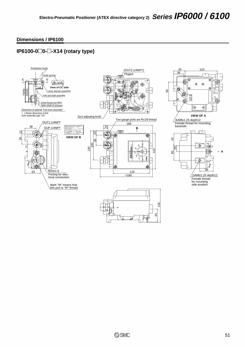
Series IP6000 / 6100 Electro-Pneumatic Positioner (ATEX directive category 2)
Dimensions / IP6100
IP6100-00--X14 (rotary type)
24
2163
(39)
770
(46) M
Pa
bar
SM
CM
Pa
bar
SM
CM
Pa
MP
abarbar
SM
CS
MC
MP
aM
Pa
barbar
SM
CS
MC
42
22.5
65
3540 110
2050
46
122
=180125
130 10
035
15
15168
4411
6
1135
38
53
Positioner body
Dimension of optional ''Fork lever assembly''( ) Shows dimension of fork lever assembly type ''SX''
Hold spring
Fork and shaft assembly
Lever and pin assembly
Main shaft of actuator
View of CC side
CC
Screw thread size M6x1
B
NP
E
M
OUT1.1/4NPT
SUP.1/4NPT
A
E
PE
MO
DE
LIP6100
90 o
60 o
30 o30 o
60 o
90 o
Oo
OUT2
DA
0
SPAN
E
MA
OUT2
M20x1.5Porting for elec-trical connection
Mark ''M'' means that this port is ''M'' thread
VIEW OF B
Zero adjusting knob
(OUT2.1/4NPT)Pluged
Two gauge ports are Rc1/8 threadVIEW OF A
4xM8x1.25 depth12Female thread for mounting, backside.
Female thread for mounting, side position
2xM8x1.25 depth12
SMC Corporation 1-16-4 Shinbashi Minatoku Tokyo 105-8659 Japan
KEMA No.03ATEX1119EExIb CT5 Ta≤80CEExIb CT6 Ta≤60C
UI≤28V II≤125mA P≤1.2V CI≤0nf LI≤0nH20** MADE IN JAPAN
Serial No.*****SUPPLY 0.14 to 0.7MPa(1.4 to 7bar)MODEL NO. IP6*00-0*0-*-X14-*
INPUT 0/4 to 20mADC
SMC ELECTRO-PNEUMATIC POSITIONER
51
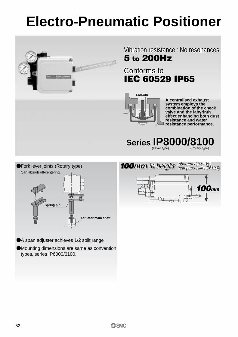
Electro-Pneumatic Positioner
Series IP8000/8100 (Lever type) (Rotary type)
EXH.AIR
Fork lever joints (Rotary type)Can absorb off-centering.
A span adjuster achieves 1/2 split range
Mounting dimensions are same as convention types, series IP6000/6100.
Spring pin
Actuator main shaft
100mm100mm
Vibration resistance : No resonances5 to 200HzConforms toIEC 60529 IP65
Vibration resistance : No resonances5 to 200HzConforms toIEC 60529 IP65
A centralised exhaust system employs the combination of the check valve and the labyrinth effect enhancing both dust resistance and water resistance performance.
100mm in height (shortened by 13% y 13% compared with IP6100) compared with IP6100)100mm in height (shortened by 13% y 13% compared with IP6100) compared with IP6100)100mm in height (shortened by 13% compared with IP6100)
52
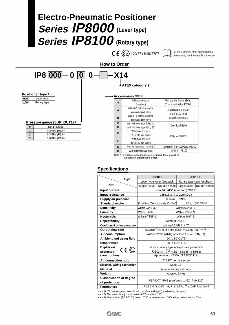
Lever type lever feedback Rotary type cam feedback
Single action Double action Single action Double action
4 to 20mADC (standard) Note 1)
235±15Ω (4 to 20mADC)
0.14 to 0.7MPa
10 to 85mm (Deflection angle 10 to 30°) 60 to 100° Note 2)
Within 0.1%F.S. Within 0.5%F.S.
Within ±1%F.S. Within ±2%F.S.
Within 0.75%F.S. Within 1%F.S.
Within 0.5%F.S.
Within 0.1%F.S. / °C80l/min (ANR) or more (SUP = 0.14MPa) Note 3)
Within 5l/min (ANR) or less (SUP = 0.14MPa)
–20 to 80°C (T5)
–20 to 60°C (T6)
Intrinsic safety type of explosion protection
( 0344 ΙΙ 2G EEx ib ΙΙc T5/T6)Approval no. KEMA 03 ATEX1119
1/4 NPT female screw
M20x1.5
Aluminum diecast body
Approx. 2.4kg
JISF8007, IP65 (conforms to IEC Pub.529)
Ui ≤28 V, li ≤125 mA, Pi ≤ 1.2W, Ci ≤ 0nF, Li ≤ 0mH
For more details, other specifications, dimensions, see the specific catalogue.
Electro-Pneumatic PositionerSeries IP8000 (Lever type)
Series IP8100 (Rotary type)
How to Order
Specifications
Type
Input currentInput resistanceSupply air pressureStandard strokeSensitivityLinearityHysteresisRepeatabilityCoefficient of temperatureOutput flow rateAir consumptionAmbient and using fluid temperatureExplosion protected construction
Air connection portElectrical wiring connectionMaterialWeightClassification of degreeof protectionParameters
Item
IP8000 IP8100
Note 1) 1/2 Split range is possible with the standard type (by adjusting the span).Note 2) The stroke is adjustable in 0 to 60°C and 0 to 100°Note 3) Standard air (JIS B0120): temp. 20°C, absolute press. 760mmHg, ratio humidity 65%.
IP8 000ATEX category 2
Positioner type000100
Lever typeRotary type
Pressure gauge (SUP, OUT1)0123
Not provided0.2MPa (R1/8)0.3MPa (R1/8)1.0MPa (R1/8)
Nil
A
B
CD
E
F
G
H
Without accesory (standard)
With ø0.7 output restrictor integrated pilot valve
With ø1.0 output restrictor integrated pilot valve
With fork lever type fitting MXWith fork lever type fitting SX
With lever unit for a35 to 100 mm strokeWith lever unit for a50 to 140 mm stroke
With compensation spring (A)
With external scale plate
With standard lever (10 to85 mm stroke) for IP8000
Accessories Note 1)
Note 1) If multiple accessories are required, they should be indicated in alphabetical order.
00 0
Common to IP8000and IP8100 smallcapacity actuators
Only for IP8100
Only for IP8000
X14
Common to IP8000 and IP8100Only for IP8100
II 2G EEx ib IIC T5/T6
53
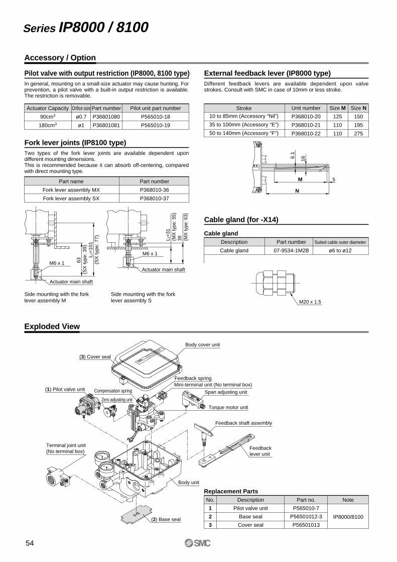
SMC
MPa
SMC
MPa
SUP
OU
AM
SPAN
ELECTORO PNEUMATIC IP8000
P O S I T I O N E R
Series IP8000 / 8100
Accessory / Option
Pilot valve with output restriction (IP8000, 8100 type)In general, mounting on a small-size actuator may cause hunting. For prevention, a pilot valve with a built-in output restriction is available. The restriction is removable.
Actuator Capacity
90cm3
180cm3
Orifice size
ø0.7
ø1
Part number
P36801080
P36801081
Pilot unit part number
P565010-18
P565010-19
Fork lever joints (IP8100 type)Two types of the fork lever joints are available dependent upon different mounting dimensions.This is recommended because it can absorb off-centering, compared with direct mounting type.
M6 x 1
Side mounting with the fork lever assembly M
63
(SX
type
: 39)
L1=
101
(SX
type
: 77)
Actuator main shaft
Side mounting with the fork lever assembly S
39
(MX
type
: 63)
L2=3
1(M
X ty
pe: 5
5)
Actuator main shaft
M6 x 1
External feedback lever (IP8000 type)
Stroke
10 to 85mm (Accessory “Nil”)
35 to 100mm (Accessory “E”)
50 to 140mm (Accessory “F”)
Unit number
P368010-20
P368010-21
P368010-22
Size M
125
110
110
Size N
150
195
275
Different feedback levers are available dependent upon valve strokes. Consult with SMC in case of 10mm or less stroke.
Cable gland (for -X14)
166.1
N
M 5Part name
Fork lever assembly MX
Fork lever assembly SX
Part number
P368010-36
P368010-37
Description
Cable gland
Part number
07-9534-1M2B
Suited cable outer diameter
ø6 to ø12
M20 x 1.5
Exploded View
Description
Pilot valve unit
Base seal
Cover seal
No.
1
2
3
Part no.
P565010-7
P56501012-3
P56501013
Note
IP8000/8100
Replacement Parts
(2) Base seal
Terminal joint unit (No terminal box)
Body unit
Feedback lever unit
Feedback shaft assembly
Mini-terminal unit (No terminal box)
(3) Cover seal
Body cover unit
Torque motor unit
Feedback spring
Compensation spring(1) Pilot valve unit
Zero adjusting unit
Span adjusting unit
Cable gland
54
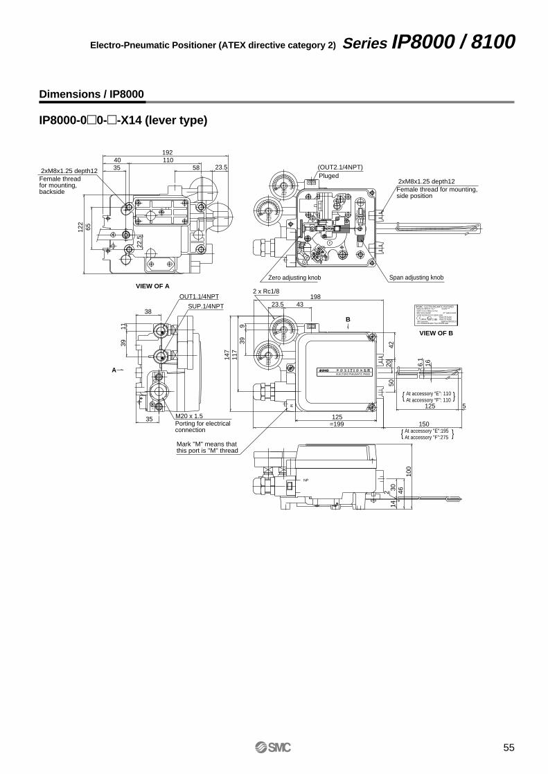
Series IP8000 / 8100 Electro-Pneumatic Positioner (ATEX directive category 2)
Dimensions / IP8000
IP8000-00--X14 (lever type)
122
65
22.5
3540
192110
58 23.5
100
4614
302
150166.
1
5125
5020
=199125
147
117
399
23.5 43
42
198
A
2 x Rc1/8
38
1139
35Porting for electrical connection
M20 x 1.5
SUP.1/4NPT
OUT1.1/4NPT
B
M
NP
barMPaSMC
barMPaSMC
E
barMPaSMC
barMPaSMC
SP
AN
E
OUT2
MA
1
E
OUT2
ELECTORO PNEUMATIC IP8000
Mark ''M'' means that this port is ''M'' thread
At accessory "E":195At accessory "F":275
At accessory “E”: 110At accessory “F”: 110
Zero adjusting knob
(OUT2.1/4NPT)
Span adjusting knob
Pluged
VIEW OF A
Female thread for mounting, backside
2xM8x1.25 depth12
SMC Corporation 1-16-4 Shinbashi Minatoku Tokyo 105-8659 Japan
KEMA No.03ATEX1119EExIb CT5 Ta≤80CEExIb CT6 Ta≤60C
UI≤28V II≤125mA P≤1.2V CI≤0nF LI≤0nH20** MADE IN JAPAN
Serial No.*****SUPPLY 0.14 to 0.7MPa(1.4 to 7bar)MODEL NO. IP8*00-0*0-*-X14-*
INPUT 0/4 to 20mADC
SMC ELECTRO-PNEUMATIC POSITIONER
VIEW OF B
Female thread for mounting, side position
2xM8x1.25 depth12
55
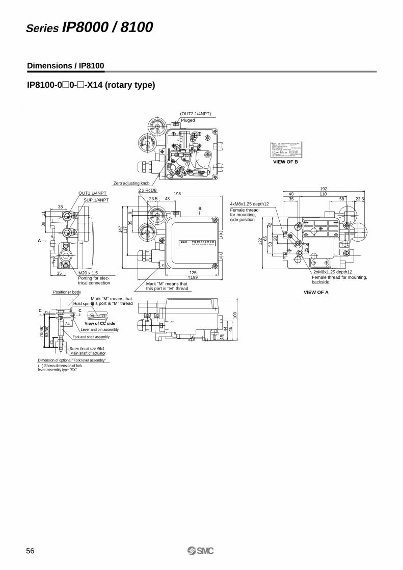
Series IP8000 / 8100
Dimensions / IP8100
IP8100-00--X14 (rotary type)
ELECTORO PNEUMATIC IP8100
35
3911
38
A
NP
100
464415
1984323.5
939
147
117
=199125
122 65
4250
20
22.5
3540
192110
58 23.5
M
B
barMPaSMC
barMPaSMC
E
barMPaSMC
barMPaSMC
E
OUT2
SPAN
MA
1
E
OUT2
24
2163
(39)
770
(46)
Positioner body
Dimension of optional ''Fork lever assembly''( ) Shows dimension of fork lever assembly type ''SX''
Hold spring
Fork and shaft assembly
Lever and pin assembly
Main shaft of actuator
View of CC side
CC
Screw thread size M6x1
OUT1.1/4NPT
SUP.1/4NPT
M20 x 1.5Porting for elec-trical connection
Mark ''M'' means that this port is ''M'' thread
2 x Rc1/8
Mark ''M'' means that this port is ''M'' thread
Zero adjusting knob
(OUT2.1/4NPT)
Pluged
VIEW OF B
SMC Corporation 1-16-4 Shinbashi Minatoku Tokyo 105-8659 Japan
KEMA No.03ATEX1119EExIb CT5 Ta≤80CEExIb CT6 Ta≤60C
UI≤28V II≤125mA P≤1.2V CI≤0nf LI≤0nH20** MADE IN JAPAN
Serial No.*****SUPPLY 0.14 to 0.7MPa(1.4 to 7bar)MODEL NO. IP6*00-0*0-*-X14-*
INPUT 0/4 to 20mADC
SMC ELECTRO-PNEUMATIC POSITIONER
VIEW OF A
4xM8x1.25 depth12
Female thread for mounting, backside.
Female thread for mounting, side position
2xM8x1.25 depth12
56

57
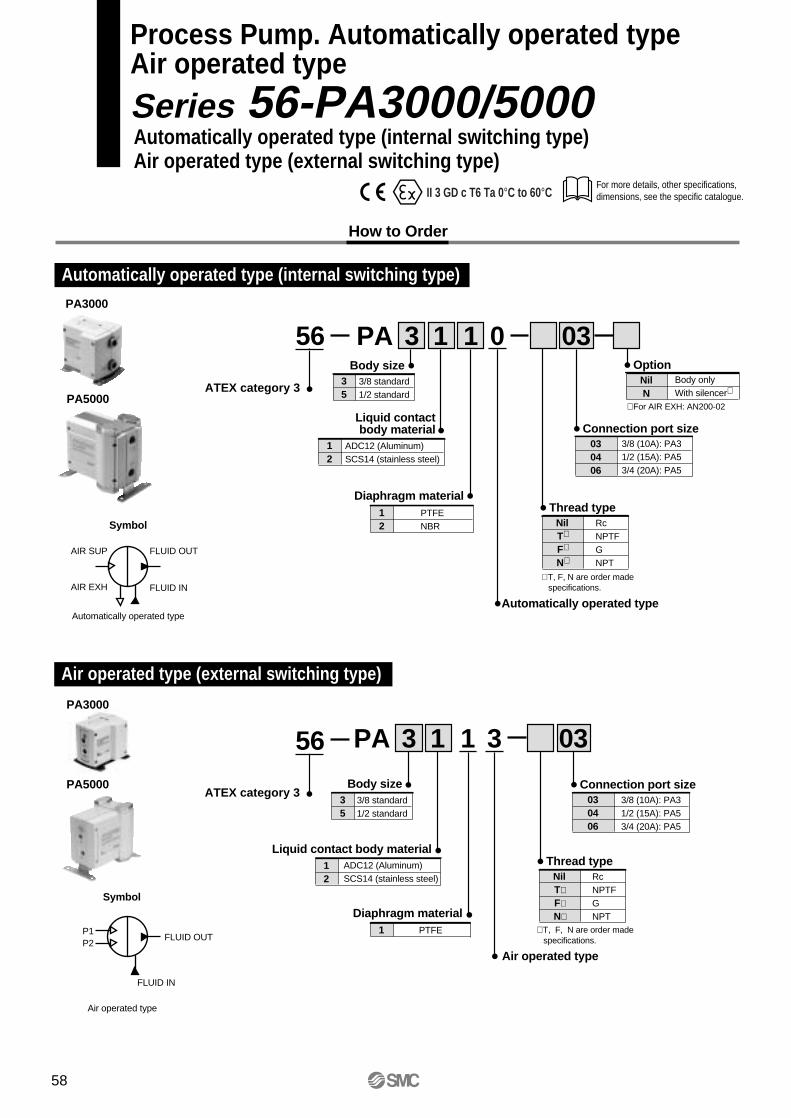
For more details, other specifications, dimensions, see the specific catalogue.
Process Pump. Automatically operated typeAir operated type
Series 56-PA3000/5000Automatically operated type (internal switching type)Air operated type (external switching type)
ATEX category 3
How to Order
035
Body size3/8 standard1/2 standard
∗ For AIR EXH: AN200-02
NilN
OptionBody onlyWith silencer∗
Automatically operated type
030406
Connection port size3/8 (10A): PA31/2 (15A): PA53/4 (20A): PA5
NilT∗
F∗
N∗
Thread typeRcNPTFGNPT
12
Diaphragm materialPTFENBR
12
Liquid contactbody material
ADC12 (Aluminum)SCS14 (stainless steel)
1 1PA 3 03
∗ T, F, N are order made specifications.
PA3000
PA5000
3
35
Body size3/8 standard1/2 standard
1
Diaphragm materialPTFE
PA3000
PA5000
Air operated type
030406
Connection port size3/8 (10A): PA31/2 (15A): PA53/4 (20A): PA5
NilT∗F∗N∗
Thread typeRcNPTFGNPT
12
Liquid contact body materialADC12 (Aluminum)SCS14 (stainless steel)
1 1PA 3 03
∗ T, F, N are order made specifications.
56
Automatically operated type (internal switching type)
Air operated type (external switching type)
ATEX category 3
56
II 3 GD c T6 Ta 0°C to 60°C
Automatically operated type
Symbol
FLUID OUTAIR SUP
AIR EXH FLUID IN
Air operated type
Symbol
FLUID OUTP1P2
FLUID IN
58
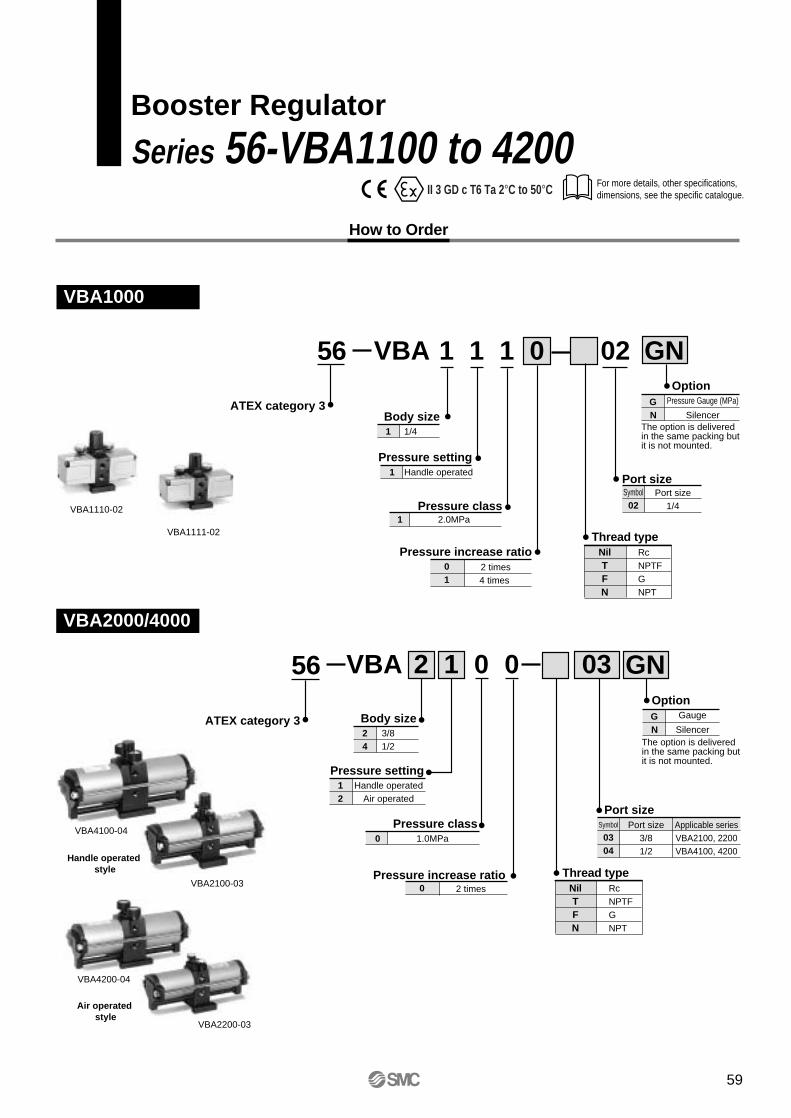
For more details, other specifications, dimensions, see the specific catalogue.
Booster Regulator
Series 56-VBA1100 to 4200
How to Order
NilTFN
Thread typeRcNPTFGNPT
VBA1000
VBA2000/4000
VBA1110-02
VBA 1 1
Port size
Port size
Body size1/41
Pressure increase ratio 2 times4 times
01
Port size1/4
Symbol02
Port size3/8
Symbol
031/2
Applicable seriesVBA2100, 2200VBA4100, 420004
021
VBA 0 0
Body size3/821/24
Pressure settingHandle operated1
Pressure settingHandle operated1
Air operated2
OptionGaugeG
SilencerN
Pressure class2.0MPa1
Pressure class1.0MPa0
0 GN
GN0312
VBA1111-02
VBA2100-03
VBA4100-04
Handle operated style
Air operated style
VBA4200-04
VBA2200-03
56
56
Pressure increase ratio 2 times0
ATEX category 3
OptionPressure Gauge (MPa)G
SilencerN
NilTFN
Thread typeRcNPTFGNPT
ATEX category 3
II 3 GD c T6 Ta 2°C to 50°C
The option is deliveredin the same packing butit is not mounted.
The option is deliveredin the same packing butit is not mounted.
59
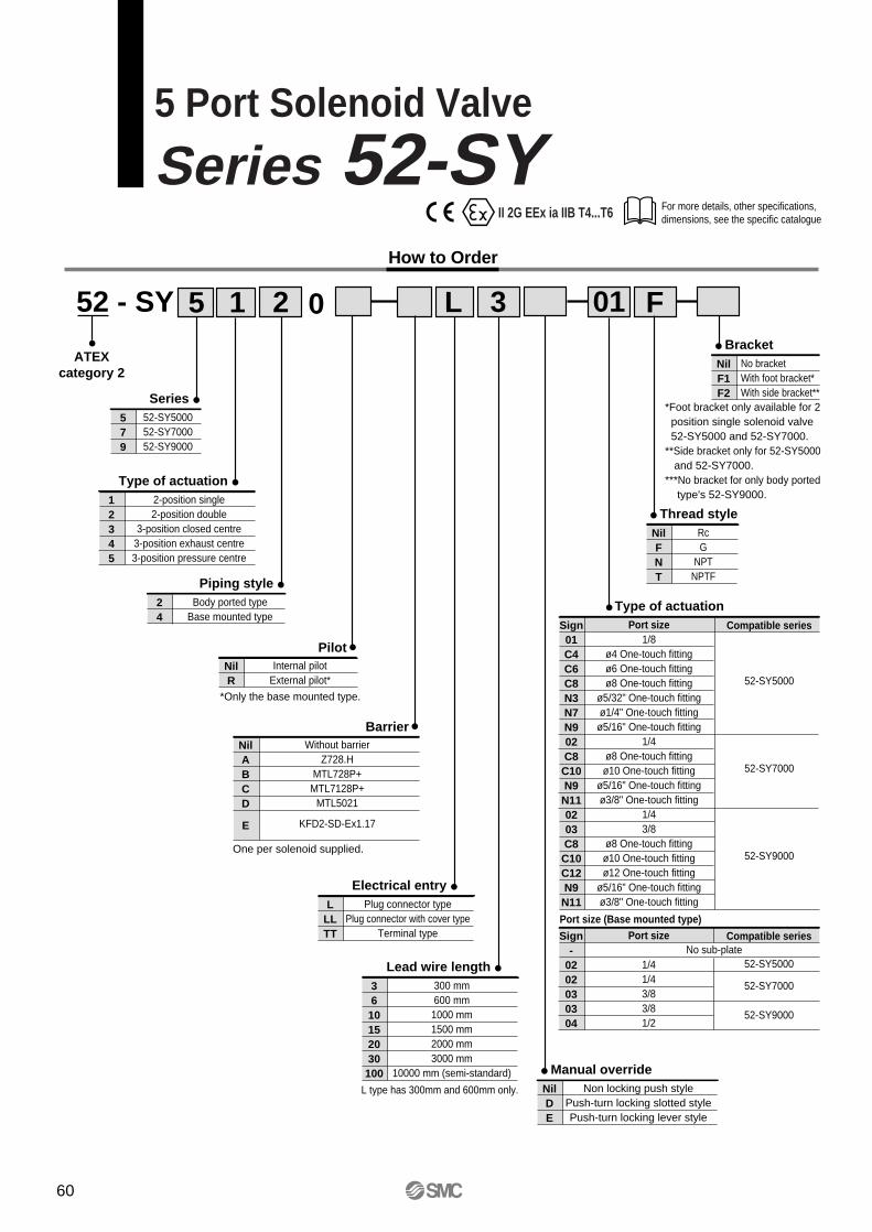
For more details, other specifications, dimensions, see the specific catalogue
5 Port Solenoid Valve
Series 52-SYHow to Order
L
Barrier
01 F352 - SY
ATEXcategory 2
Series579
52-SY500052-SY700052-SY9000
15 2 0
Type of actuation12345
2-position single2-position double
3-position closed centre3-position exhaust centre3-position pressure centre
Piping style24
Body ported typeBase mounted type
NilABCD
E
Without barrierZ728.H
MTL728P+MTL7128P+
MTL5021
KFD2-SD-Ex1.17
One per solenoid supplied.
Electrical entryL
LLTT
Plug connector typePlug connector with cover type
Terminal type
Lead wire length36
10152030
100
300 mm600 mm1000 mm1500 mm2000 mm3000 mm
10000 mm (semi-standard)
L type has 300mm and 600mm only.
BracketNilF1F2
No bracketWith foot bracket*With side bracket**
Thread styleNilFNT
RcG
NPTNPTF
*Foot bracket only available for 2 position single solenoid valve 52-SY5000 and 52-SY7000.**Side bracket only for 52-SY5000 and 52-SY7000.***No bracket for only body ported type's 52-SY9000.
*Only the base mounted type.
Type of actuationSign01C4C6C8N3N7N902C8C10N9N110203C8C10C12N9N11
Port size1/8
ø4 One-touch fittingø6 One-touch fittingø8 One-touch fitting
ø5/32" One-touch fittingø1/4" One-touch fittingø5/16" One-touch fitting
1/4ø8 One-touch fittingø10 One-touch fitting
ø5/16" One-touch fittingø3/8" One-touch fitting
1/43/8
ø8 One-touch fittingø10 One-touch fittingø12 One-touch fitting
ø5/16" One-touch fittingø3/8" One-touch fitting
Compatible series
52-SY5000
52-SY7000
52-SY9000
Sign-
0202030304
Port size
1/41/43/83/81/2
Compatible series
52-SY5000
52-SY7000
52-SY9000
Port size (Base mounted type)
No sub-plate
Manual overrideNilDE
Non locking push stylePush-turn locking slotted stylePush-turn locking lever style
PilotNilR
Internal pilotExternal pilot*
II 2G EEx ia IIB T4...T6
60
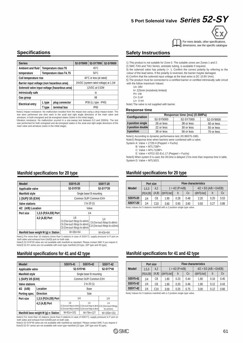
Safety Instructions
For more details, other specifications, dimensions, see the specific catalogue
Specifications
Series
Ambient and fluid
temperature
Coil temperature rise
Barrier input voltage (non hazardous area)Solenoid valve input voltage (hazardous area)
Intrinsically safe
Gas group
Electrical entry
45°C50°C
40°C or less (at rated)
24VDC (system rated voltage) at 1.1W
12VDC at 0.52W
ia
IIB
IP30 (LL type : IP40)
IP65
52-SY5000 52-SY7000
Note1) Impact resistance: No malfunction resulted from the impact test using a drop impact tester. The test were performed one time each in the axial and right angle directions of the main valve and armature, in both energised and de-energised states (Valve in the initial stage).Vibration resistance: No malfunction ocurred in a one-sweep test between 8.3 and 2000Hz. The test was performed for both energised and de-energised states in the axial and right angle directions of the main valve and armature (valve in the initial stage).
5 Port Solenoid Valve Series 52-SY
52-SY9000Temperature class T6
Temperature class T4, T5
L type
T type
plug connector
terminal box
1) This product is not suitable for Zone 0. The suitable zones are Zones 1 and 2.2) SMC-TAS and TAU Series, antistatic tubing, is available if required.3) the solenoid valve has polarity (+ -). Confirm the correct polarity by referring to the colour of the lead wires. If the polarity is reversed, the barrier maybe damaged.4) Confirm that the solenoid input voltage at the lead wires is DC 10.8V (min).5) The product must be connected to a certified barrier or certified intrinsically safe circuit with the follow maximum Values:
Ui= 28Vli= 225mA (resistively limited)Pi= 1WCi= 0.nFLi= 0 nH
Note) The valve is not supplied with barrier.
Response time
Configuration
2-position single2-position double3-position
52-SY500026 or less22 or less38 or less
52-SY700038 or less30 or less56 or less
52-SY900050 or less50 or less70 or less
Response time (ms) (0.5MPa)
Note1) According to dynamic performance test JIS B8375-1981.Note2) Response time when barriers were combined with a valve.System A: Valve + Z728.H (Pepperl + Fuchs)
B: Valve + MTL728P+C: Valve + MTL7128P+E: Valve + KFD2-SD-Ex1.17 (Pepperl + Fuchs)
Note3) When system D is used, the ON time is delayed 17ms more than response time in table.System D: Valve + MTL5021
Manifold specifications for 20 type
Model
Applicable valve
Manifold style
1 (SUP)/ 3/5 (EXH)
Valve stations4/2 (A/B) Location
Port size
Manifold base weight W (g) n: Station
Single base/ B mounting
Common SUP/ Common EXH
2 to 20 (1)
Valve
1/4
SS5Y5-2052-SY5*20
Note1) For more than 10 stations (more than 5 stations in case of SS5Y7), supply pressure to P port on both sides and exhaust from EA/EB port on both side.Note2) 52-SY9*20 valve are not available with manifold as standard. Please contact SMC if you require it:Note3) 52-SY series are not available with resin type manifold (23 type, 20P type and 45 type).
SS5Y7-2052-SY7*20
1,3,5 (P,EA,EB) Port
4,2 (A,B) Port 1/8C4 (One-touch fittings for ø4mm)C6 (One-touch fittings for ø6mm)C8 (One-touch fittings for ø8mm)
1/4C8 (One-touch fittings for ø8mm)
C10 (One-touch fittings for ø10mm)
W=36n+64 W=43n+64
Manifold specifications for 20 type
Model
SS5Y5-20
SS5Y7-20Note) Values for 5 stations manifold with a 2 position single type valve.
Port size Flow characteristics1 > 4/2 (P>A/B) 4/2 > 5/3 (A/B > EA/EB)1,5,3
(P,EA,EB)
1/4
1/4
4,2(A,B)
C8
C10
c[dm3/(s.bar)]
1.90
3.60
b
0.28
0.93
Cv
0.48
3.60
c[dm3/(s.bar)]
2.20
0.93
b
0.20
0.27
Cv
0.53
0.88
Manifold specifications for 41 and 42 type
Model
Applicable valve
Manifold style
1 (SUP)/ 3/5 (EXH)
Valve stations4/2 (A/B)
Porting spec.
Port size
Manifold base weight W (g) n: Station
Single base/ B mounting
Common SUP/ Common EXH
2 to 20 (1)
Base
Side
SS5Y5-41 SS5Y5-42
Note1) For more than 10 stations (more than 5 stations in case of SS5Y7), supply pressure to P port on both sides and exhaust from EA/EB port on both side.Note2) 52-SY9*40 valve are not available with manifold as standard. Please contact SMC if you require it:Note3) 52-SY series are not available with resin type manifold (23 type, 20P type and 45 type).
SS5Y7-4252-SY7*40
Location
Direction
1,3,5 (P,EA,EB) Port
4,2 (A,B) Port
1/4 1/41/8
C6 (One-touch fittings for ø6mm)C8 (One-touch fittings for ø8mm)
1/4C6 (One-touch fittings for ø6mm)C8 (One-touch fittings for ø8mm)
1/4C10 (One-touch fittings
for ø10mm)
W=61n+101 W=79n+127 W=100n+151
Manifold specifications for 41 and 42 type
Model
SS5Y5-41
SS5Y5-42
SS5Y7-42Note) Values for 5 stations manifold with a 2 position single type valve.
Port size Flow characteristics1 > 4/2 (P>A/B) 4/2 > 5/3 (A/B > EA/EB)1,5,3
(P,EA,EB)
1/4
1/4
1/4
4,2(A,B)
C8
C8
C10
c[dm3/(s.bar)]
1.80
1.90
3.00
b
0.23
0.20
0.25
Cv
0.44
0.46
0.75
c[dm3/(s.bar)]
1.90
1.90
3.00
b
0.16
0.12
0.12
Cv
0.45
0.43
0.66
52-SY5*40
61
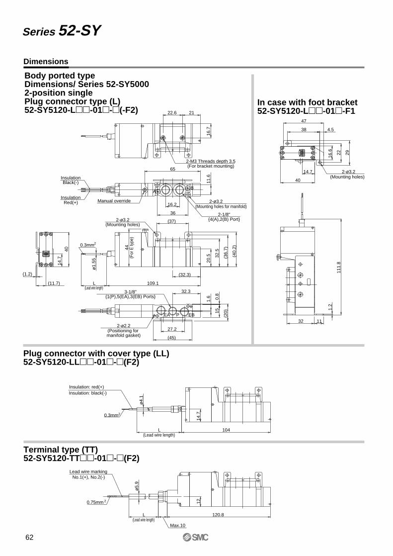
(Mounting holes for manifold)
Dimensions
Series 52-SY
1214
.7
L 104
Max.10
L 120.8
ø5.
9ø
4.1
111.
8
32 11
40
14.7
47
4.538
2922
16.6
1.2
109.1L
(45)
ø1.
55
32.3
14.7
(1.2)
(11.7)
16.7
(40.
2)
(36.
7)(37)
36
16.2
21
40
65
(32.3)
44
32.5
(20)
11.6
0.8
15
1.6
22.6
20.5
27.2
(Lead wire length)
(Lead wire length)
Insulation: black(-)Insulation: red(+)
(Mounting holes)2-ø3.2
(Lead wire length)
(For
E ty
pe)
(For bracket mounting)2-M3 Threads depth 3.5
2-ø3.2
(Mounting holes)2-ø3.2
(Positioning for manifold gasket)
2-ø2.2
No.1(+), No.2(-)Lead wire marking
0.75mm 2
0.3mm2
Manual override
0.3mm2
Red(+)Insulation
Black(-)Insulation
1(P),5(EA),3(EB) Ports3-1/8"
4(A),2(B) Port2-1/8"
EBPEA
AB
Body ported typeDimensions/ Series 52-SY50002-position singlePlug connector type (L)52-SY5120-L-01-(-F2)
In case with foot bracket52-SY5120-L-01-F1
Plug connector with cover type (LL)52-SY5120-LL-01-(F2)
Terminal type (TT)52-SY5120-TT-01-(F2)
62
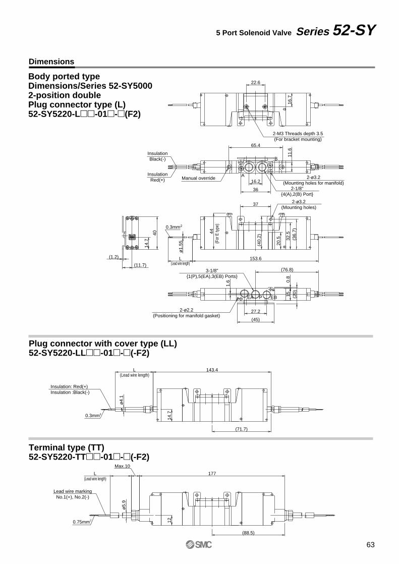
Dimensions
5 Port Solenoid Valve Series 52-SY
(88.5)
(71.7)
14.7
12
(76.8)
L 153.6
11.6
16.2
36
65.414
.7
40
(11.7)
(1.2)
37
(40.
2)
20.5 32
.5(3
6.7)44
0.8
(20)15
1.6
27.2
(45)
ø1.
55
16.7
22.6
177
143.4
ø5.
9ø
4.1
L
Max.10
L
(Lead wire length)
(Lead wire length)
Insulation: Red(+)Insulation :Black(-)
(Lead wire length)
2-M3 Threads depth 3.5(For bracket mounting)
2-ø3.2(Mounting holes for manifold)
2-ø3.2(Mounting holes)
2-ø2.2(Positioning for manifold gasket)
Lead wire markingNo.1(+), No.2(-)
Manual overrideInsulation
Red(+)
InsulationBlack(-)
(For
E ty
pe)
0.75mm2
0.3mm2
2-1/8"4(A),2(B) Port
3-1/8"1(P),5(EA),3(EB) Ports
EBPEA
A
B
0.3mm2
Body ported typeDimensions/Series 52-SY50002-position doublePlug connector type (L)52-SY5220-L-01-(F2)
Plug connector with cover type (LL)52-SY5220-LL-01-(-F2)
Terminal type (TT)52-SY5220-TT-01-(-F2)
63
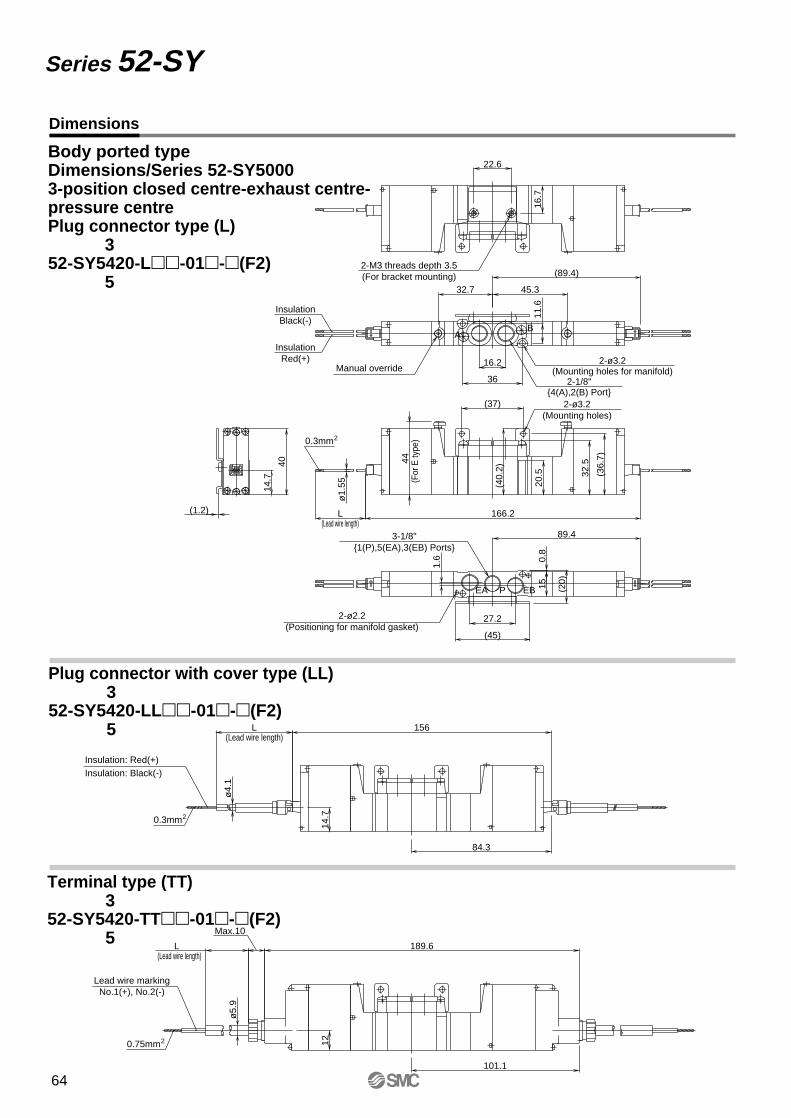
Dimensions
Series 52-SY
Body ported typeDimensions/Series 52-SY50003-position closed centre-exhaust centre-pressure centrePlug connector type (L)
52-SY5420-L-01-(F2)
101.1
84.3
14.7
12
189.6
156
32.7 45.3
(89.4)
32.5
(36.
7)
89.4
L 166.2
11.6
16.2
36
14.7
40
(1.2)
(37)
(40.
2)
20.5
44
0.8
(20)15
1.6
27.2
(45)
ø1.
55
16.7
22.6
ø5.
9ø
4.1
L
Max.10
L
(Lead wire length)
(Lead wire length)
Insulation: Red(+)Insulation: Black(-)
(Lead wire length)
2-M3 threads depth 3.5(For bracket mounting)
2-ø3.2(Mounting holes for manifold)
2-ø3.2(Mounting holes)
2-ø2.2(Positioning for manifold gasket)
Lead wire markingNo.1(+), No.2(-)
Manual override
InsulationRed(+)
InsulationBlack(-)
(For
E ty
pe)0.3mm2
2-1/8"4(A),2(B) Port
3-1/8"1(P),5(EA),3(EB) Ports
EBPEA
AB
0.75mm2
0.3mm2
3
5
Plug connector with cover type (LL)
52-SY5420-LL-01-(F2)3
5
Terminal type (TT)
52-SY5420-TT-01-(F2)3
5
64
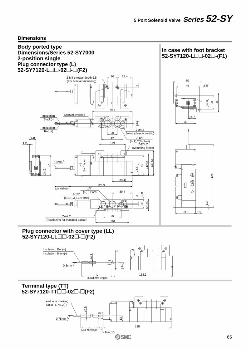
2-1/8"5(EA),3(EB) Ports
2-ø4.2(Mounting holes for manifold)
Dimensions
5 Port Solenoid Valve Series 52-SY
Body ported typeDimensions/Series 52-SY70002-position single Plug connector type (L)52-SY7120-L-02-(F2)
14.7
12
135
ø5.
9
L
Max.10
L 118.2
ø4.
1
19.8
28 38
46 5.5
57
40
14.7
1.2
125
39.5 13
123.3L
42
20
(52)
14.7
(14)
1.2
40
(66)
39.4
(49.
5)
(42.
5)
40
24.5
7
29.420
(23.
9)
36
2 0.9
18
13.6
79.2
(39.4)
44
(Lead wire length)
(Lead wire length)
Insulation: Red(+)Insulation: Black(-)
(Lead wire length)
2-M4 threads depth 6.5(For bracket mounting)
2-ɔ4.2(Mounting holes)
2-ø2.2(Positioning for manifold gasket)
Lead wire markingNo.1(+), No.2(-)
Manual override
InsulationRed(+)
InsulationBlack(-)
2-1/4"4(A),2(B) Port
(For
E ty
pe)
0.75mm2
0.3mm2
0.3mm2
1/4"1(P) Port
B
A
EBPEA
In case with foot bracket52-SY7120-L-02-(F1)
Plug connector with cover type (LL)52-SY7120-LL-02-(F2)
Terminal type (TT)52-SY7120-TT-02-(F2)
65
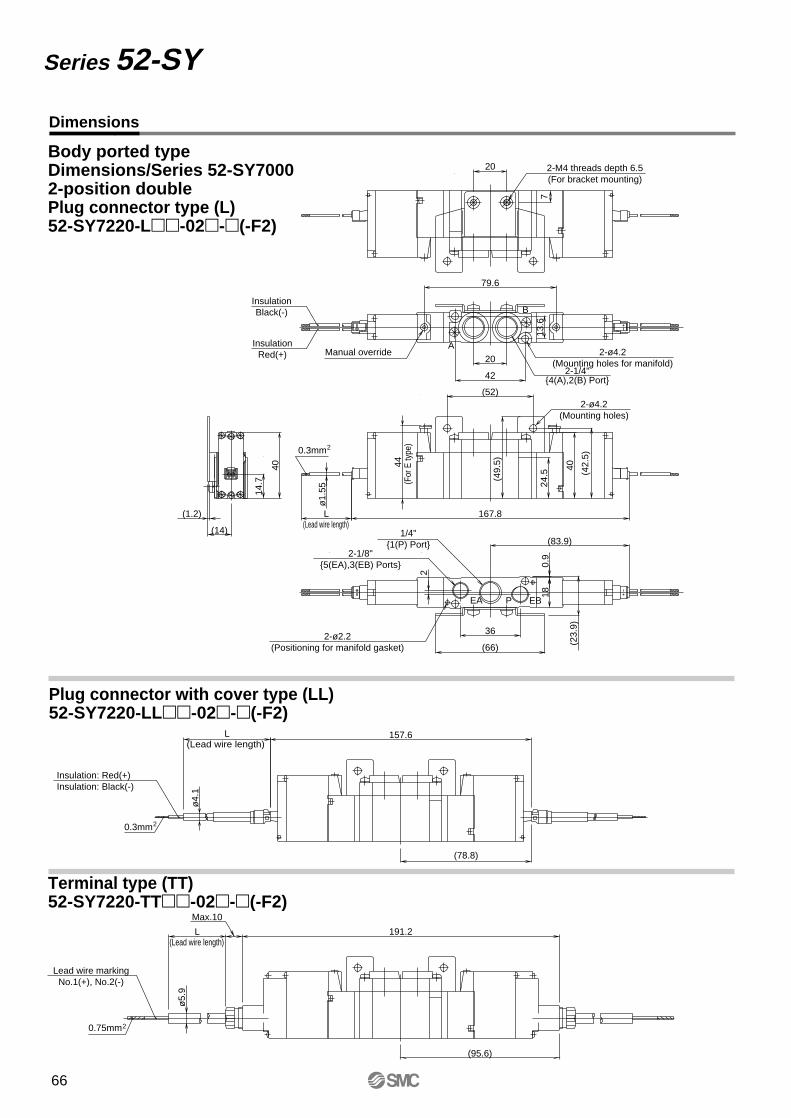
Dimensions
Series 52-SY
Body ported typeDimensions/Series 52-SY70002-position double Plug connector type (L)52-SY7220-L-02-(-F2)
(78.8)
Max.10
L 191.2
(95.6)
ø5.
9ø
4.1
L 157.6
7
20
(1.2)
(14)
(23.
9)
0.9
18(83.9)
79.6
ø1.
55
L 167.8
2
42
20
(52)
14.7
40
(66)
(49.
5)
(42.
5)
40
24.5
36
13.6
44
(Lead wire length)
(Lead wire length)
Insulation: Red(+)Insulation: Black(-)
(Lead wire length)
2-M4 threads depth 6.5(For bracket mounting)
2-ø4.2(Mounting holes for manifold)
2-ø4.2(Mounting holes)
2-ø2.2(Positioning for manifold gasket)
Lead wire markingNo.1(+), No.2(-)
Manual overrideInsulation
Red(+)
InsulationBlack(-)
2-1/4"4(A),2(B) Port
(For
E ty
pe)
1/4"1(P) Port
2-1/8"5(EA),3(EB) Ports
0.75mm2
0.3mm2
0.3mm2
B
A
EBPEA
Plug connector with cover type (LL)52-SY7220-LL-02-(-F2)
Terminal type (TT)52-SY7220-TT-02-(-F2)
66
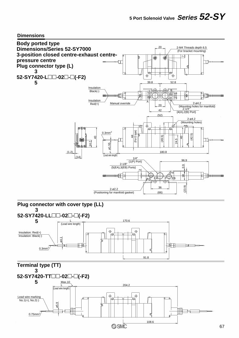
Dimensions
5 Port Solenoid Valve Series 52-SY
Body ported typeDimensions/Series 52-SY70003-position closed centre-exhaust centre-pressure centrePlug connector type (L)
52-SY7420-L-02-(-F2)52.839.8
91.8
Max.10L 204.2
108.6
ø5.
9ø
4.1
L 170.6
7
20
(1.2)
(14)
(23.
9)0.
918
96.9
ø1.
55
L 180.8
2
42
20
(52)
14.7
40
(66)
(49.
5)
(42.
5)
40
24.5
36
13.6
44
(Lead wire length)
(Lead wire length)
Insulation: Red(+)Insulation: Black(-)
(Lead wire length)
2-M4 Threads depth 6.5(For bracket mounting)
2-ø4.2(Mounting holes for manifold)
2-ø4.2(Mounting holes)
2-ø2.2(Positioning for manifold gasket)
Lead wire markingNo.1(+), No.2(-)
Manual overrideInsulation
Red(+)
InsulationBlack(-)
2-1/4"4(A),2(B) Port
(For
E ty
pe)
1/4"1(P) Port
2-1/8"5(EA),3(EB) Ports
0.75mm2
0.3mm2
0.3mm2
B
A
EBPEA
3
5
Plug connector with cover type (LL)
52-SY7420-LL-02-(-F2)3
5
Terminal type (TT)
52-SY7420-TT-02-(-F2)3
5
67
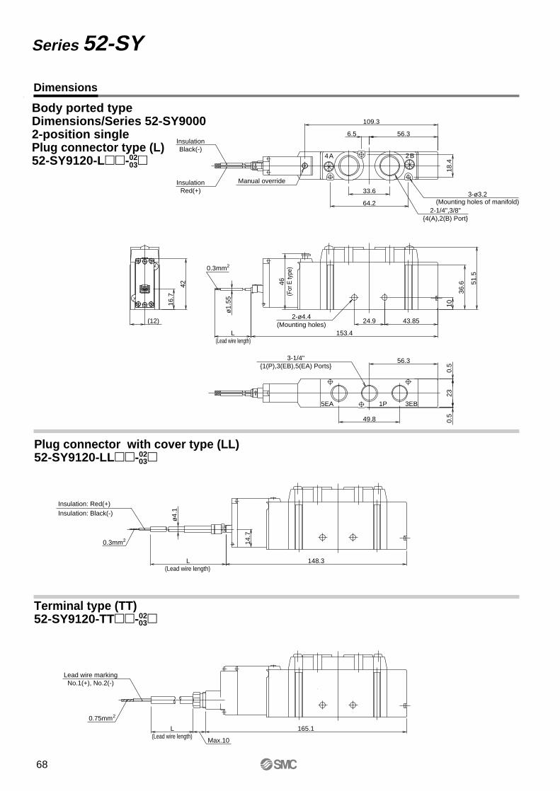
Dimensions
Series 52-SY
Body ported typeDimensions/Series 52-SY90002-position singlePlug connector type (L)52-SY9120-L-02
Max.10
L 165.1
ø4.
1
14.7
L 148.3
36.6
153.4
ø1.
55
L
(12)
42
10
46
24.9 43.85
56.3
18.4
109.3
6.5 56.3
64.2
33.6
51.5
49.8
230.
50.
5
16.7
(Lead wire length)
(Lead wire length)
Insulation: Red(+)Insulation: Black(-)
(Lead wire length)
3-ø3.2(Mounting holes of manifold)
2-ø4.4(Mounting holes)
Lead wire markingNo.1(+), No.2(-)
Manual overrideInsulationRed(+)
InsulationBlack(-)
(For
E ty
pe)
0.75mm2
0.3mm2
2-1/4",3/8"4(A),2(B) Port
0.3mm2
3-1/4"1(P),3(EB),5(EA) Ports
B2A4
3EB1P5EA
03
Plug connector with cover type (LL)52-SY9120-LL-0203
Terminal type (TT)52-SY9120-TT-0203
68
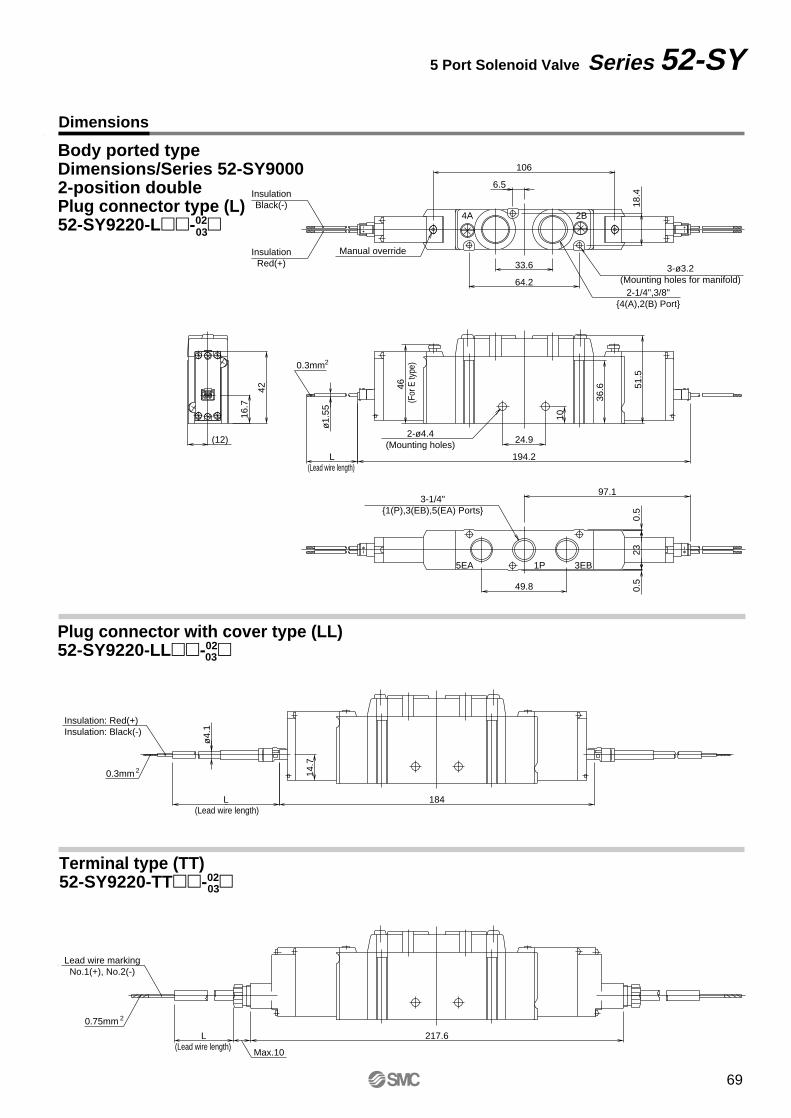
Dimensions
5 Port Solenoid Valve Series 52-SY
Body ported typeDimensions/Series 52-SY90002-position doublePlug connector type (L)52-SY9220-L-02
217.6
184
106
194.2
97.1
Max.10
L
ø4.
1
14.7
L
36.6
ø1.
55
L
(12)
42
10
46
24.9
18.4
6.5
64.2
33.6
51.5
49.8
230.
50.
5
16.7
(Lead wire length)
(Lead wire length)
Insulation: Red(+)Insulation: Black(-)
(Lead wire length)
3-ø3.2(Mounting holes for manifold)
2-ø4.4(Mounting holes)
Lead wire markingNo.1(+), No.2(-)
Manual overrideInsulationRed(+)
InsulationBlack(-)
(For
E ty
pe)
2-1/4",3/8"4(A),2(B) Port
3-1/4"1(P),3(EB),5(EA) Ports
0.75mm 2
0.3mm 2
0.3mm2
2B4A
3EB1P5EA
03
Plug connector with cover type (LL)52-SY9220-LL-0203
Terminal type (TT)52-SY9220-TT-0203
69
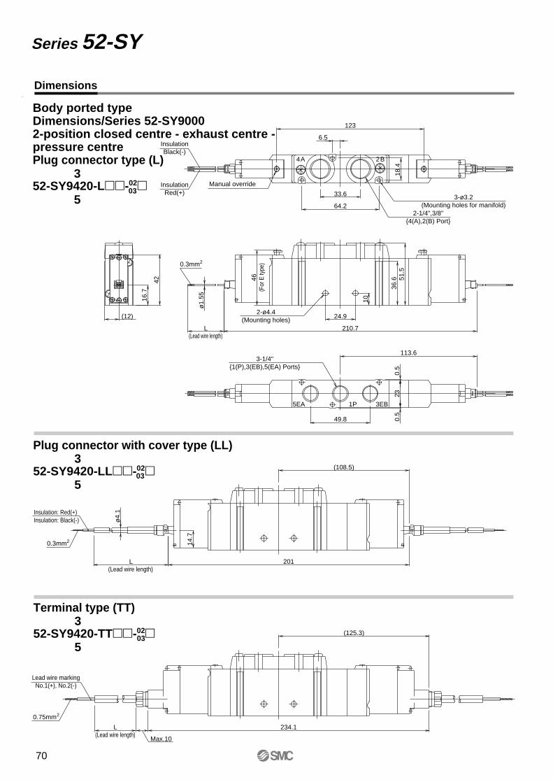
Dimensions
Series 52-SY
(108.5)
(125.3)
234.1
201
123
210.7
113.6
Max.10
L
ø4.
1
14.7
L
36.6
ø1.
55
L
(12)
42
10
46
24.9
18.4
6.5
64.2
33.6
51.5
49.8
230.
50.
5
16.7
(Lead wire length)
(Lead wire length)
Insulation: Red(+)Insulation: Black(-)
(Lead wire length)
3-ø3.2(Mounting holes for manifold)
2-ø4.4(Mounting holes)
Lead wire markingNo.1(+), No.2(-)
Manual overrideInsulationRed(+)
InsulationBlack(-)
(For
E ty
pe)
2-1/4",3/8"4(A),2(B) Port
3-1/4"1(P),3(EB),5(EA) Ports
0.75mm2
0.3mm2
0.3mm2
B2A4
3EB1P5EA
Body ported typeDimensions/Series 52-SY90002-position closed centre - exhaust centre - pressure centrePlug connector type (L)
52-SY9420-L-0203
3
5
Plug connector with cover type (LL)
52-SY9420-LL-0203
3
5
Terminal type (TT)
52-SY9420-TT-0203
3
5
70
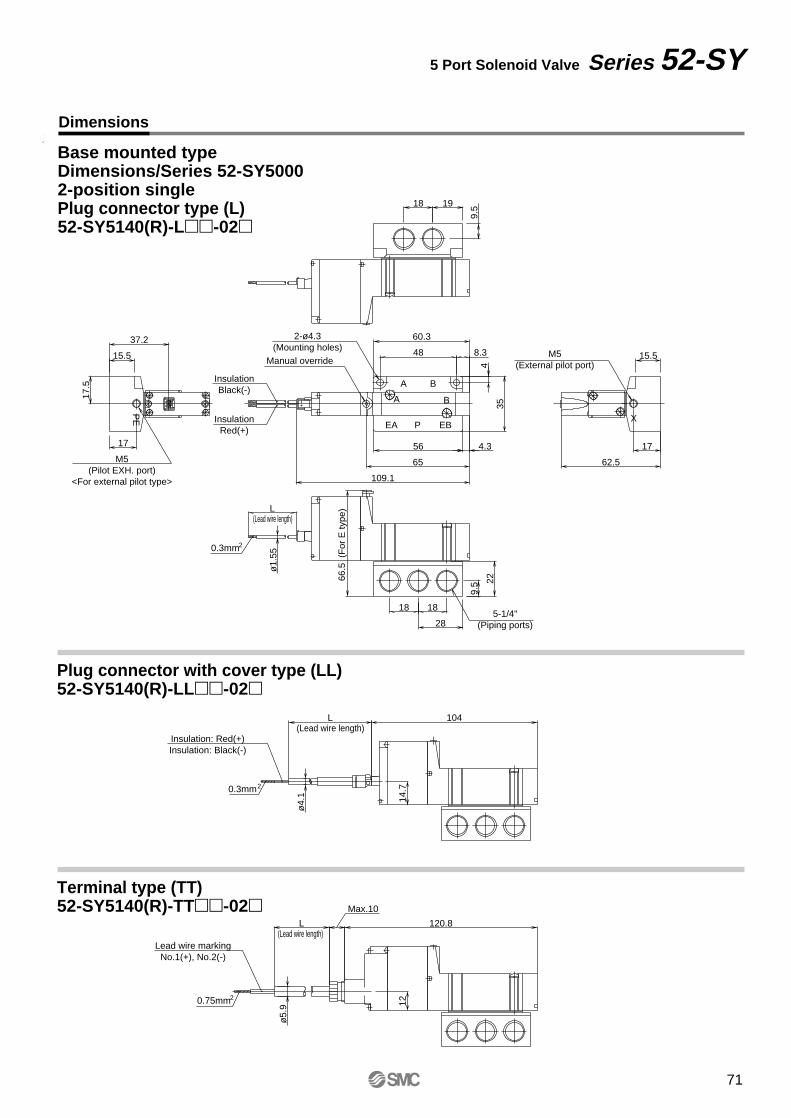
Dimensions
5 Port Solenoid Valve Series 52-SY
Base mounted typeDimensions/Series 52-SY50002-position singlePlug connector type (L)52-SY5140(R)-L-02
1214
.7
Max.10
L 120.8
ø5.
9
L 104
ø4.
1
17.5
65
109.1
4.356
35
4
60.3
8.34837.2
L
66.5
(F
or E
type
)
62.5
17
ø1.
55
17
15.5 15.5
19
22
9.5
28
18 18
9.518
(Lead wire length)
(Lead wire length)
(Lead wire length)
Lead wire markingNo.1(+), No.2(-)
0.75mm2
Insulation: Red(+)Insulation: Black(-)
0.3mm2
0.3mm2
InsulationRed(+)
InsulationBlack(-)
Manual override
A B
M5(Pilot EXH. port)
<For external pilot type>
PE X
M5(External pilot port)
P EBEA
BA
5-1/4"(Piping ports)
2-ø4.3(Mounting holes)
Plug connector with cover type (LL)52-SY5140(R)-LL-02
Terminal type (TT)52-SY5140(R)-TT-02
71
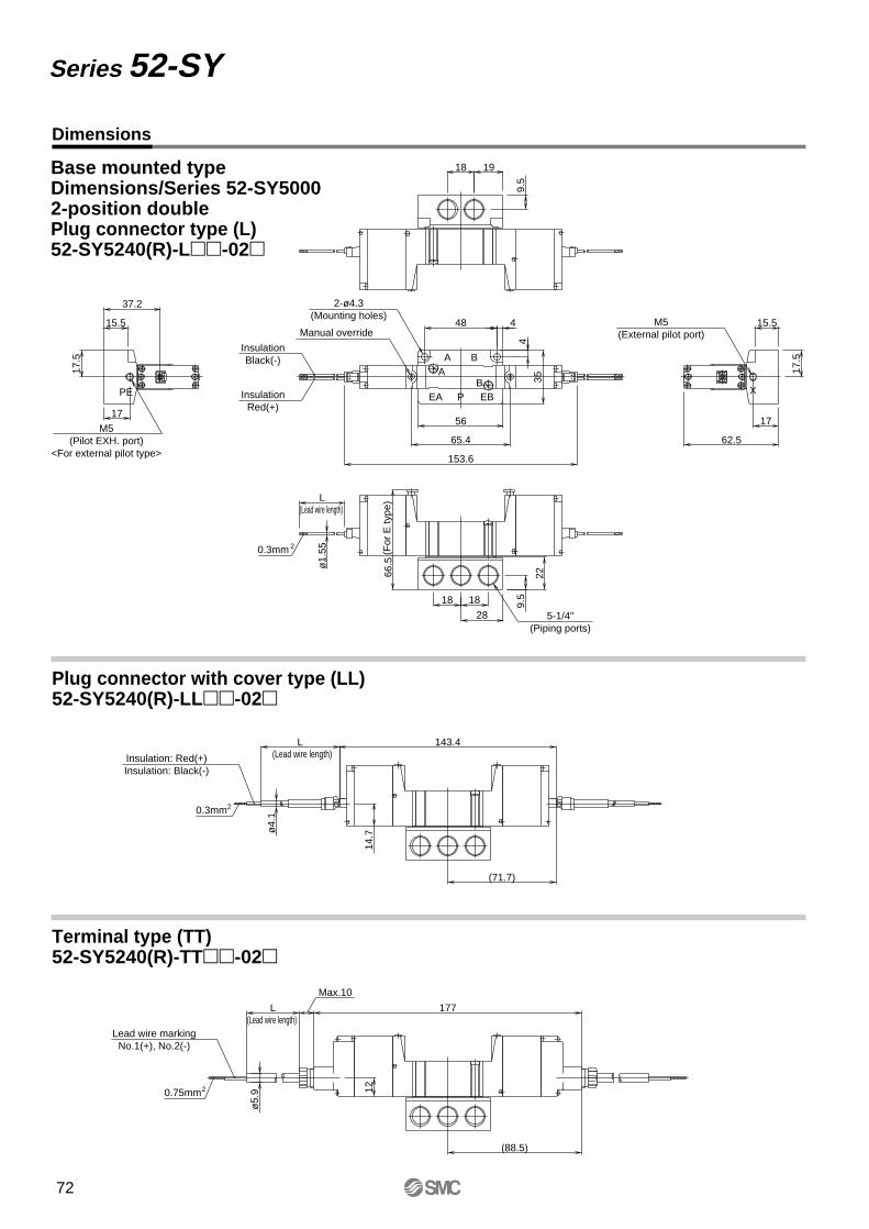
Dimensions
Series 52-SY
Base mounted typeDimensions/Series 52-SY50002-position doublePlug connector type (L)52-SY5240(R)-L-02
Plug connector with cover type (LL)52-SY5240(R)-LL-02
Terminal type (TT)52-SY5240(R)-TT-02
153.6
L
ø1.
55
1214
.7
(71.7)
(88.5)
143.4
Max.10
177L
ø5.
9
L
ø4.
1
62.5
4
17.5
65.4
17.5
56
35
4
48
37.2
66.5
1717
15.5 15.5
19
22
9.5
28
18 18
9.5
18
(Lead wire length)
(Lead wire length)
(Lead wire length)
(For
E ty
pe)
InsulationRed(+)
InsulationBlack(-)
0.3mm 2
Lead wire markingNo.1(+), No.2(-)
0.75mm2
Insulation: Red(+)Insulation: Black(-)
0.3mm2
Manual override
AB
M5(Pilot EXH. port)
<For external pilot type>
PE X
M5(External pilot port)
P EBEA
BA
5-1/4"(Piping ports)
2-ø4.3(Mounting holes)
72
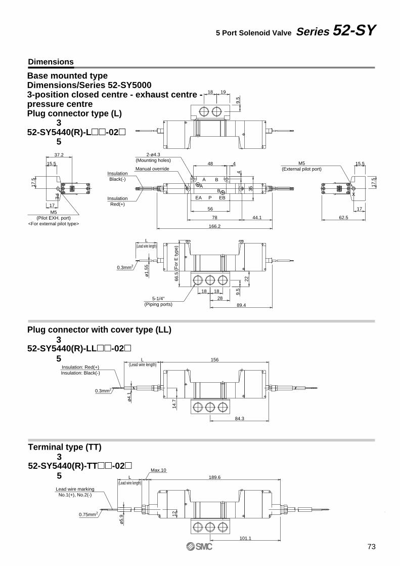
Dimensions
5 Port Solenoid Valve Series 52-SY
Base mounted typeDimensions/Series 52-SY50003-position closed centre - exhaust centre - pressure centrePlug connector type (L)
52-SY5440(R)-L-02
Plug connector with cover type (LL)
52-SY5440(R)-LL-02
Terminal type (TT)
52-SY5440(R)-TT-02
84.3
89.4
44.1
166.2
L
ø1.
55
14.7
156L
ø4.
1
62.5
4
17.5
78
17.5
56
35
4
48
37.2
66.5
1717
15.5 15.5
19
22
9.5
28
18 18
9.5
18
(Lead wire length)
(Lead wire length)
(For
E ty
pe)
InsulationRed(+)
InsulationBlack(-)
0.3mm2
Insulation: Red(+)Insulation: Black(-)
0.3mm2
Manual override
AB
M5(Pilot EXH. port)
<For external pilot type>
PE
M5(External pilot port)
P EBEA
BA
5-1/4"(Piping ports)
2-ø4.3(Mounting holes)
101.1
12
Max.10
189.6L
ø5.
9
(Lead wire length)Lead wire marking
No.1(+), No.2(-)
0.75mm2
3
5
3
5
3
5
X
73
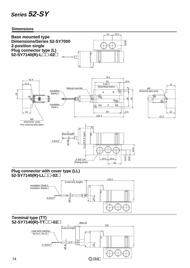
Dimensions
Series 52-SY
Base mounted typeDimensions/Series 52-SY70002-position singlePlug connector type (L)52-SY7140(R)-L-02
Plug connector with cover type (LL)52-SY7140(R)-LL-02
Terminal type (TT)52-SY7140(R)-TT-02 Max.10
L 135
12
ø5.
9
L 118.2
14.7
ø4.
1ø
1.55
4
23
71.2
67.2
L
21
41.9
123.3
6.4
10.4
79.2
69
22.5
38 46
21
21
21.5
13.5
21
61
26.5
13.5
11.5
33
20.5 20.5
(Lead wire length)
(Lead wire length)
(For
E ty
pe)
(Lead wire length)
Lead wire markingNo.1(+), No.2(-)
0.75mm2
Insulation: Red(+)Insulation: Black(-)
0.3mm2
InsulationRed(+)
InsulationBlack(-)
0.3mm2
Manual override
BA
P
BA
EBEA
PE
X
M5(Pilot EXH. port)
<For external pilot type>
M5(External pilot port)
5-3/8",1/4"(Piping ports)
2-ø4.3(Mounting holes)
74
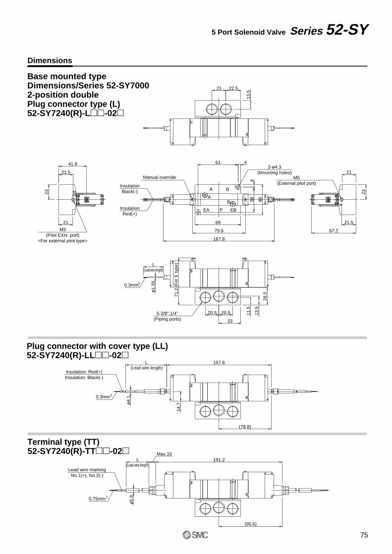
Dimensions
5 Port Solenoid Valve Series 52-SY
Base mounted typeDimensions/Series 52-SY70002-position doublePlug connector type (L)52-SY7240(R)-L-02
Plug connector with cover type (LL)52-SY7240(R)-LL-02
Terminal type (TT)52-SY7240(R)-TT-02
ø5.
9
Max.10L
(95.6)
(78.8)
191.2
ø4.
1
14.7
L 157.6
13.5
26.5
11.5
20.5 20.5
33
ø1.
55
L
71.2
21
23
41.9
21.5
21.5
67.2
23
21
167.8
79.6
69
384
46
461
13.5
21 22.5
(Lead wire length)
(Lead wire length)
(For
E ty
pe)
(Lead wire length)
0.75mm2
Lead wire markingNo.1(+), No.2(-)
0.3mm2
Insulation: Red(+)Insulation: Black(-)
5-3/8",1/4"(Piping ports)
0.3mm2
M5(Pilot EXH. port)
<For external pilot type>
M5(External pilot port)
InsulationRed(+)
InsulationBlack(-)
Manual override
2-ø4.3(Mounting holes)
PE
BA
P
BA
EBEA
X
75
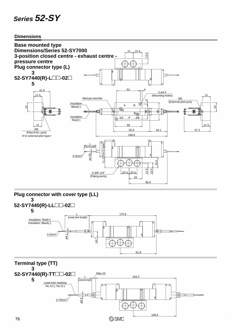
3
5
3
5
Dimensions
Series 52-SY
Base mounted typeDimensions/Series 52-SY70003-position closed centre - exhaust centre -pressure centrePlug connector type (L)
52-SY7440(R)-L-02
Plug connector with cover type (LL)
52-SY7440(R)-LL-02
Terminal type (TT)
52-SY7440(R)-TT-02
96.9
44.1
91.8
ø4.
1
14.7
L 170.6
13.5
26.5
11.5
20.5 20.5
33
ø1.
55
L
71.2
21
23
41.9
21.5
21.5
67.2
23
21
180.8
92.6
69
384
46
461
13.5
21 22.5
(Lead wire length)
(For
E ty
pe)
(Lead wire length)
0.3mm2
Insulation: Red(+)Insulation: Black(-)
5-3/8",1/4"(Piping ports)
0.3mm2
M5(Pilot EXH. port)
<For external pilot type>
M5(External pilot port)
InsulationRed(+)
InsulationBlack(-)
Manual override
2-ø4.3(Mounting holes)
PE
BA
P
BA
EBEA
X
ø5.
9
Max.10L
108.6
204.2(Lead wire length)
0.75mm2
Lead wire markingNo.1(+), No.2(-)
3
5
76
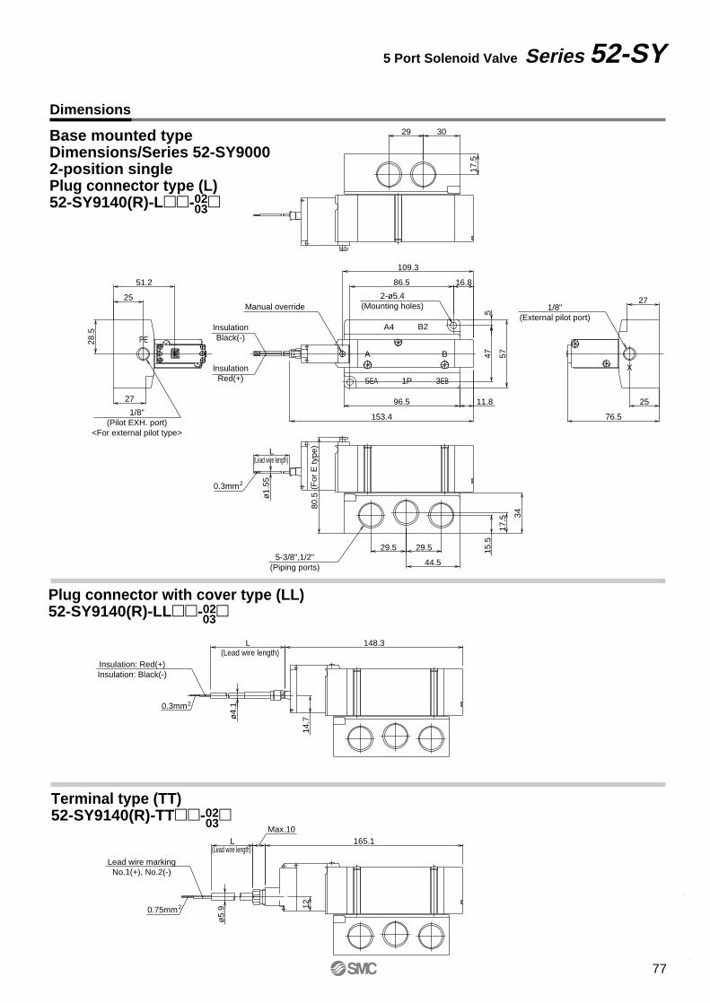
Dimensions
5 Port Solenoid Valve Series 52-SY
Base mounted typeDimensions/Series 52-SY90002-position singlePlug connector type (L)52-SY9140(R)-L-02
Plug connector with cover type (LL)52-SY9140(R)-LL-02
Terminal type (TT)52-SY9140(R)-TT-02
11.8
153.4
16.8
109.3
14.7
L 148.3
ø4.
1
ø1.
55
L
80.5
51.2
76.5
28.5
515
.5
17.5 34
29.5 29.5
44.5
25
86.5
5747
96.527 25
27
17.5
29 30
Manual override
(Lead wire length)
(Lead wire length)
(For
E ty
pe)
Insulation: Red(+)Insulation: Black(-)
0.3mm2
0.3mm2
InsulationRed(+)
InsulationBlack(-)
5-3/8",1/2"(Piping ports)
A B
1/8"(Pilot EXH. port)
<For external pilot type>
1/8"(External pilot port)
2-ø5.4(Mounting holes)
X
A4 B2
3EB1P5EA
PE
03
03
12
Max.10L 165.1
ø5.
9
(Lead wire length)
Lead wire markingNo.1(+), No.2(-)
0.75mm2
03
77
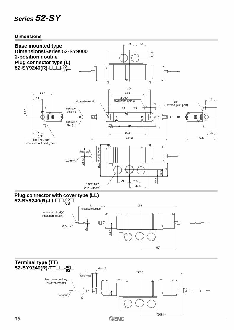
Dimensions
Series 52-SY
Base mounted typeDimensions/Series 52-SY90002-position doublePlug connector type (L)52-SY9240(R)-L-02
Plug connector with cover type (LL)52-SY9240(R)-LL-02
Terminal type (TT)52-SY9240(R)-TT-02
03
03
03
(108.8)
217.6
(92)
184
76.5
27
25
194.2
106
12
Max.10L
14.7
L
ø4.
1
ø5.
9ø
1.55
L
80.5
51.2
28.5
515
.5
17.5 34
29.5 29.5
44.5
25
86.5
5747
96.527
17.5
29 30
Manual override
(Lead wire length)
(Lead wire length)
(Lead wire length)
(For
E ty
pe)
Lead wire markingNo.1(+), No.2(-)
Insulation: Red(+)Insulation: Black(-)
0.3mm2
0.75mm2
0.3mm2
InsulationRed(+)
InsulationBlack(-)
5-3/8",1/2"(Piping ports)
A B
1/8"(Pilot EXH. port)
<For external pilot type>
1/8"(External pilot port)
2-ø5.4(Mounting holes)
X
4A 2B
3EB1P5EA
PE
78

Dimensions
5 Port Solenoid Valve Series 52-SY
Base mounted typeDimensions/Series 52-SY90003-position closed centre - exhaust centre - Pressure centrePlug connector type (L)
52-SY9440(R)-L-02
Plug connector with cover type (LL)
52-SY9440(R)-LL-02
Terminal type (TT)
52-SY9440(R)-TT-02
03
03
113.6
69.1
76.5
27
25
210.7
123
ø1.
55
L
80.5
51.2
28.5
5
15.5
17.5 34
29.5 29.5
44.5
25
86.5
5747
96.527
17.5
29 30
(For
E ty
pe)(Lead wire length)
Manual override
0.3mm2
InsulationRed(+)
InsulationBlack(-)
5-3/8",1/2"(Piping ports)
A B
1/8"(Pilot EXH. port)
<For external pilot type>
1/8"(External pilot port)
2-ø5.4(Mounting holes)
A4 B2
3EB1P5EA
PE
108
200
14.7
L
ø4.
1
(Lead wire length)Insulation: Red(+)Insulation: Black(-)
0.3mm2
03
125.3
234.1
12
Max.10L
ø5.
9
(Lead wire length)Lead wire marking
No.1(+), No.2(-)
0.75mm2
3
5
3
5
3
5
X
79
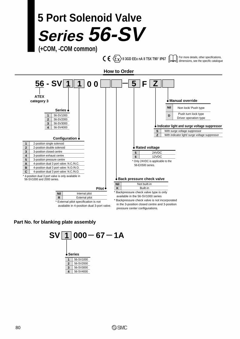
For more details, other specifications, dimensions, see the specific catalogue
5 Port Solenoid Valve
Series 56-SV
How to Order
56 - SVATEX
category 3
Pilot
Z
Series1234
56-SV100056-SV200056-SV300056-SV4000
511 0 0
Configuration12345ABC
2-position single solenoid2-position double solenoid3-position closed centre3-position exhaust centre3-position pressure centre4-position dual 3 port valve: N.C./N.C.4-position dual 3 port valve: N.O./N.O.4-position dual 3 port valve: N.C./N.O.
NilR
Internal pilotExternal pilot
* External pilot specification is not available in 4-position dual 3-port valve.
Back pressure check valveNilK
Not built-inBuilt-in
Rated voltage56
24VDC12VDC
* Only 24VDC is applicable to the 56-EX500 series.
Manual override
Nil
D
Non lock/ Push type
Push turn lock typeDriver operation type
Indicator light and surge voltage suppressor
(+COM, -COM common)
F
* 4-position dual 3 port valve is only available in 56-SV1000 and 2000 series.
* Backpressure check valve type is only available in the 56-SV1000 series* Backpressure check valve is not incorporated in the 3-position closed centre and 3-position pressure center configurations.
SZ
With surge voltage suppressorWith indicator light/ surge voltage suppressor
Part No. for blanking plate assembly
SV 000 67 1A1
Series1234
56-SV100056-SV200056-SV300056-SV4000
II 3GD EEx nA II T5X T90° IP67
80
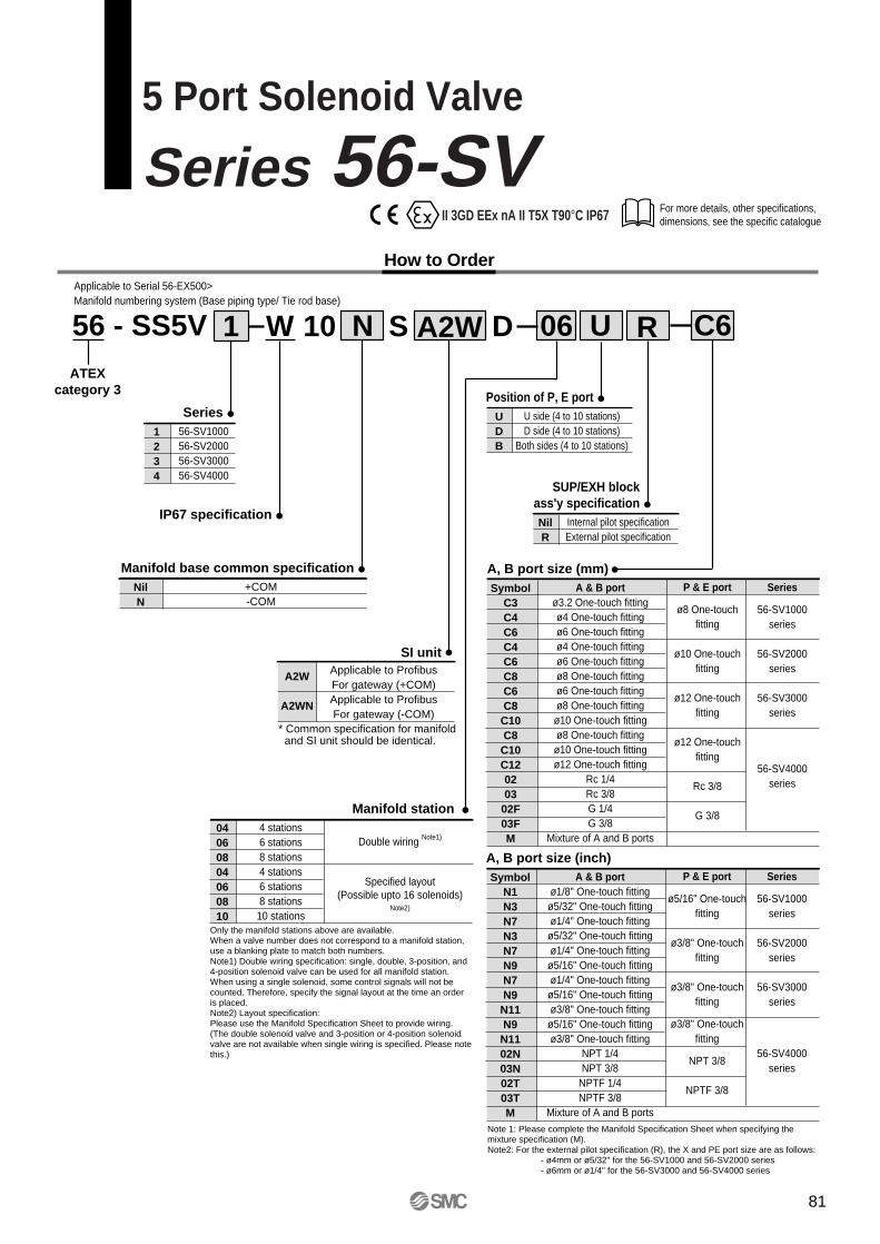
For more details, other specifications, dimensions, see the specific catalogue
5 Port Solenoid Valve
Series 56-SVHow to Order
56 - SS5VATEX
category 3
06 C6
Series1234
56-SV100056-SV200056-SV300056-SV4000
UW1 N10 R
Position of P, E portUDB
U side (4 to 10 stations)D side (4 to 10 stations)
Both sides (4 to 10 stations)
Manifold base common specificationNilN
+COM-COM
Manifold station04060804060810
4 stations6 stations8 stations4 stations6 stations8 stations10 stations
Double wiring Note1)
Specified layout(Possible upto 16 solenoids)
Note2)
S A2W D
IP67 specification
SI unit
A2W
A2WN
Applicable to ProfibusFor gateway (+COM)Applicable to ProfibusFor gateway (-COM)
* Common specification for manifold and SI unit should be identical.
Only the manifold stations above are available.When a valve number does not correspond to a manifold station, use a blanking plate to match both numbers.Note1) Double wiring specification: single, double, 3-position, and 4-position solenoid valve can be used for all manifold station.When using a single solenoid, some control signals will not be counted. Therefore, specify the signal layout at the time an order is placed.Note2) Layout specification:Please use the Manifold Specification Sheet to provide wiring.(The double solenoid valve and 3-position or 4-position solenoid valve are not available when single wiring is specified. Please note this.)
A, B port size (mm)Symbol
C3C4C6C4C6C8C6C8C10C8C10C120203
02F03FM
A & B portø3.2 One-touch fittingø4 One-touch fittingø6 One-touch fittingø4 One-touch fittingø6 One-touch fittingø8 One-touch fittingø6 One-touch fittingø8 One-touch fittingø10 One-touch fittingø8 One-touch fittingø10 One-touch fittingø12 One-touch fitting
Rc 1/4Rc 3/8G 1/4G 3/8
Mixture of A and B ports
P & E port
ø8 One-touchfitting
ø10 One-touchfitting
ø12 One-touchfitting
ø12 One-touchfitting
Rc 3/8
G 3/8
Series
56-SV1000series
56-SV2000series
56-SV3000series
56-SV4000series
A, B port size (inch)Symbol
N1N3N7N3N7N9N7N9N11N9N1102N03N02T03TM
A & B portø1/8" One-touch fittingø5/32" One-touch fittingø1/4" One-touch fittingø5/32" One-touch fittingø1/4" One-touch fittingø5/16" One-touch fittingø1/4" One-touch fittingø5/16" One-touch fittingø3/8" One-touch fittingø5/16" One-touch fittingø3/8" One-touch fitting
NPT 1/4NPT 3/8
NPTF 1/4NPTF 3/8
Mixture of A and B ports
P & E port
ø5/16" One-touchfitting
ø3/8" One-touchfitting
ø3/8" One-touchfitting
ø3/8" One-touchfitting
NPT 3/8
NPTF 3/8
Series
56-SV1000series
56-SV2000series
56-SV3000series
56-SV4000series
Note 1: Please complete the Manifold Specification Sheet when specifying the mixture specification (M).Note2: For the external pilot specification (R), the X and PE port size are as follows:
- ø4mm or ø5/32" for the 56-SV1000 and 56-SV2000 series- ø6mm or ø1/4" for the 56-SV3000 and 56-SV4000 series
SUP/EXH blockass'y specificationNilR
Internal pilot specificationExternal pilot specification
Applicable to Serial 56-EX500>Manifold numbering system (Base piping type/ Tie rod base)
II 3GD EEx nA II T5X T90°C IP67
81
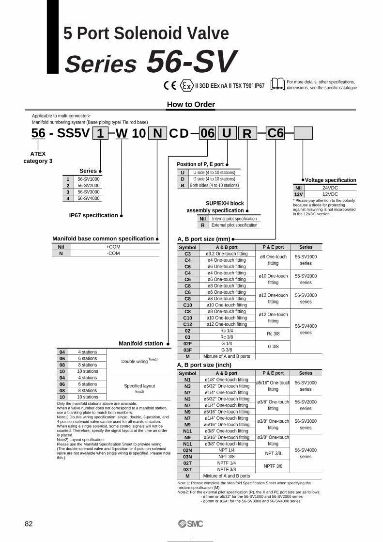
For more details, other specifications, dimensions, see the specific catalogue
5 Port Solenoid Valve
Series 56-SVHow to Order
56 - SS5VATEX
category 3
06 C6
Series1234
56-SV100056-SV200056-SV300056-SV4000
UW1 N10 R
Position of P, E portUDB
U side (4 to 10 stations)D side (4 to 10 stations)
Both sides (4 to 10 stations)
Manifold base common specificationNilN
+COM-COM
Manifold station0406081004060810
4 stations6 stations8 stations
10 stations4 stations6 stations8 stations
10 stations
Double wiring Note1)
Specified layoutNote2)
CD
IP67 specification
Only the manifold stations above are available.When a valve number does not correspond to a manifold station, use a blanking plate to match both numbers.Note1) Double wiring specification: single, double, 3-position, and 4-position solenoid valve can be used for all manifold station.When using a single solenoid, some control signals will not be counted. Therefore, specify the signal layout at the time an order is placed.Note2) Layout specification:Please use the Manifold Specification Sheet to provide wiring.(The double solenoid valve and 3-position or 4-position solenoid valve are not available when single wiring is specified. Please note this.)
A, B port size (mm)Symbol
C3C4C6C4C6C8C6C8C10C8C10C120203
02F03FM
A & B portø3.2 One-touch fittingø4 One-touch fittingø6 One-touch fittingø4 One-touch fittingø6 One-touch fittingø8 One-touch fittingø6 One-touch fittingø8 One-touch fittingø10 One-touch fittingø8 One-touch fittingø10 One-touch fittingø12 One-touch fitting
Rc 1/4Rc 3/8G 1/4G 3/8
Mixture of A and B ports
P & E port
ø8 One-touchfitting
ø10 One-touchfitting
ø12 One-touchfitting
ø12 One-touchfitting
Rc 3/8
G 3/8
Series
56-SV1000series
56-SV2000series
56-SV3000series
56-SV4000series
A, B port size (inch)Symbol
N1N3N7N3N7N9N7N9N11N9N1102N03N02T03TM
A & B portø1/8" One-touch fittingø5/32" One-touch fittingø1/4" One-touch fittingø5/32" One-touch fittingø1/4" One-touch fittingø5/16" One-touch fittingø1/4" One-touch fittingø5/16" One-touch fittingø3/8" One-touch fittingø5/16" One-touch fittingø3/8" One-touch fitting
NPT 1/4NPT 3/8
NPTF 1/4NPTF 3/8
Mixture of A and B ports
P & E port
ø5/16" One-touchfitting
ø3/8" One-touchfitting
ø3/8" One-touchfitting
ø3/8" One-touchfitting
NPT 3/8
NPTF 3/8
Series
56-SV1000series
56-SV2000series
56-SV3000series
56-SV4000series
Note 1: Please complete the Manifold Specification Sheet when specifying the mixture specification (M).Note2: For the external pilot specification (R), the X and PE port size are as follows:
- ø4mm or ø5/32" for the 56-SV1000 and 56-SV2000 series- ø6mm or ø1/4" for the 56-SV3000 and 56-SV4000 series
SUP/EXH blockassembly specification
NilR
Internal pilot specificationExternal pilot specification
Applicable to multi-connector>Manifold numbering system (Base piping type/ Tie rod base)
Voltage specificationNil12V
24VDC12VDC
* Please pay attention to the polarity because a diode for protecting against miswiring is not incorporated in the 12VDC version.
II 3GD EEx nA II T5X T90° IP67
82
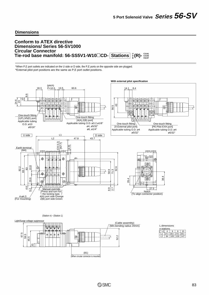
B 2
A 4
B 2 B 2 B 2
A 4 A 4 A 4
1 P
3/5 E 3/5
1 P
E
A
B
A
B
A
B
A
B
AB
AB
12
3
4 5
6
78
9
10
1112
13
1415
1617
18 19
2021
22
23
2425 26
E
1 P
35
B 2
A 4
B 2 B 2 B 2
A 4 A 4 A 4
1 P
5 3 E
PEX PEX
One-touch fitting[X:External pilot port]
Applicable tubing O.D.:ø4 ø5/32"
2.7
106.
2
26.4
43.747.8
67.5
52.2
71.3
8.9
8.414.1
92.6
58.910
.829
.6
4.6
83
56.5 43
(C6:
3.2)
(N7:
7)
(4.9
)
60.6
L1
(81)
27.5
38.4
L2
24.6
8.6
P=10.5 13.5
59.5
2310
45.5
18.3
92.2
83.7
Notch(To align connector position)
One-touch fitting[PE:Pilot EXH.port]
Applicable tubing O.D.:ø4 ø5/32"
(Cable assembly)(Min.bending radius 20mm)
(When circular connector is mounted)
With external pilot specification
14712610584L2200.3179.3158.3137.3
L:dimensionsn:stationsL n 10864L1
Light/Surge voltage suppressor
4-ø4.3(For mounting)
Earth terminal(M4)
D side U side
One-touch fitting[4(A),2(B) port]
Applicable tubing O.D.:ø3.2,ø1/8" ø4, ø5/32" ø6, ø1/4"
One-touch fitting[1(P),3/5(E) port]Applicable tubing
O.D.:ø10 ø5/16"
(pitch)
(Station 1)(Station n)
Manual overridePress and turn forthe locking type.
4(A) port side:Orange2(B) port side:Green
( )
Dimensions
5 Port Solenoid Valve Series 56-SV
*When P,E port outlets are indicated on the U side or D side, the P,E ports on the opposite side are plugged.*External pilot port positions are the same as P,E port outlet positions.
B C6,N7
Conform to ATEX directiveDimensions/ Series 56-SV1000Circular ConnectorTie-rod base manifold: 56-SS5V1-W10CD- Stations (R)-D
UC4,N3C3,N1
83
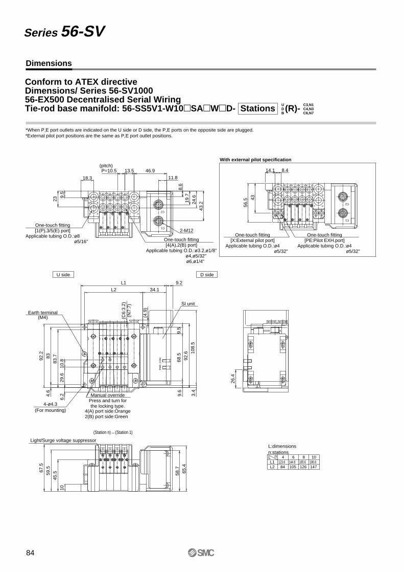
A
B
A
B
A
B
A
B
AB
AB
CO
MP
WR
E
1 P
35
B 2
A 4
B 2 B 2 B 2
A 4 A 4 A 4
1 P
5 3 E
PEX PEX
C1
C2E
1 P
35
B 2
A 4
B 2 B 2 B 2
A 4 A 4 A 4
1 P
5 3 E
C1
C2
2-M12
B C6,N7
Conform to ATEX directiveDimensions/ Series 56-SV100056-EX500 Decentralised Serial WiringTie-rod base manifold: 56-SS5V1-W10SAWD- Stations (R)-D
UC4,N3C3,N1
Dimensions
Series 56-SV
3.4
108.
5
4.6
83
6.2
9.2
34.1
26.4
65.4
67.5
56.5 43
8.414.1
92.6
68.5
9.6
10.8
29.6
9.5
L1
13.5
11.8
43.219
.7
10
92.2
18.3
24.6
8.6
46.9
(C6:
3.2)
(N7:
7)
83.7
L2
59.5
23
9.5
P=10.5
(4.9
)
45.5 58
.7
*External pilot port positions are the same as P,E port outlet positions.*When P,E port outlets are indicated on the U side or D side, the P,E ports on the opposite side are plugged.
14712610584186.6165.6144.6123.6
L:dimensionsn:stations
L2L1
L n 10864
Light/Surge voltage suppressor
4-ø4.3(For mounting)
D side U side
With external pilot specification
One-touch fitting[X:External pilot port]
Applicable tubing O.D.:ø4 ø5/32"
One-touch fitting[PE:Pilot EXH.port]
Applicable tubing O.D.:ø4 ø5/32"
SI unit
4(A) port side:Orange2(B) port side:Green
One-touch fitting[4(A),2(B) port]
Applicable tubing O.D.:ø3.2,ø1/8" ø4,ø5/32" ø6,ø1/4"
(pitch)
(Station 1)(Station n)
One-touch fitting[1(P),3/5(E) port]
Applicable tubing O.D.:ø8 ø5/16"
Manual overridePress and turn forthe locking type.
Earth terminal(M4)
84
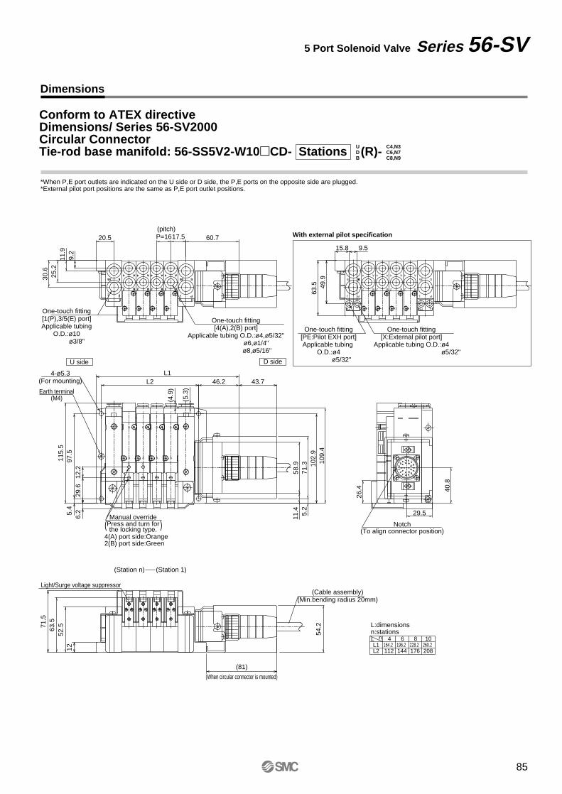
60.7
30.6
11.9
P=1617.5
25.2
9.2
20.5
3/5
One-touch fitting[4(A),2(B) port]
Applicable tubing O.D.:ø4,ø5/32" ø6,ø1/4"
ø8,ø5/16"
One-touch fitting[1(P),3/5(E) port]Applicable tubing
O.D.:ø10 ø3/8"
(pitch)
E
1 P
4
2
4
2
A
B
4
2
A
B
3/5 E
P1
4
2
A
B
A
B
9.515.8
63.5 49
.9One-touch fitting
[X:External pilot port]Applicable tubing O.D.:ø4
ø5/32"
One-touch fitting[PE:Pilot EXH port]Applicable tubing
O.D.:ø4 ø5/32"
3/54
2
A
B
E
1 P
4
2
A
B
4
2
A
B
4
2
A
B
XPE
3/5 E
P1
PE
D side U side
5.2
43.746.2
6.2
71.3
L1
102.
9
(5.3
)
109.
4
58.9
11.4
12.2
29.6
5.4
97.5
L2
(4.9
)
115.
5
4-ø5.3(For mounting)
4(A) port side:Orange2(B) port side:Green
Manual overridePress and turn forthe locking type.( )
26.4 40
.8
29.5
Notch(To align connector position)
71.5
54.2
(81)
63.5
52.5
12
(Cable assembly)(Min.bending radius 20mm)
Light/Surge voltage suppressor
(When circular connector is mounted)
(Station 1)(Station n)
Earth terminal(M4)
208176144260.2228.2196.2164.2
112L2
L:dimensionsn:stationsL n 10864L1
With external pilot specification
A
B
AB
AB
A
B
A
B
A
B
12
3
4 5
6
78
9
10
1112
13
1415
1617
18 19
2021
22
23
2425 26
P1
E
B
A
2
4
B
A
2
4
B
A
2
4
B
A
2
4
1 P
E3/53/5
B C8,N9
Conform to ATEX directiveDimensions/ Series 56-SV2000Circular ConnectorTie-rod base manifold: 56-SS5V2-W10CD- Stations (R)-D
UC6,N7C4,N3
Dimensions
5 Port Solenoid Valve Series 56-SV
*When P,E port outlets are indicated on the U side or D side, the P,E ports on the opposite side are plugged.*External pilot port positions are the same as P,E port outlet positions.
85
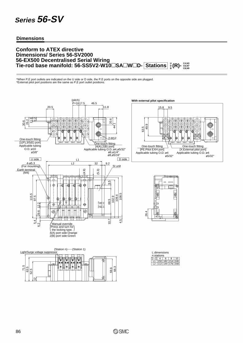
44.120
.6
30.6 11
.9
P=1617.5 46.511.8
25.2 9.
2
20.5
2-M12
One-touch fitting[4(A),2(B) port]
Applicable tubing O.D.:ø4,ø5/32" ø6,ø1/4"
ø8,ø5/16"
One-touch fitting[1(P),3/5(E) port]Applicable tubing
O.D.:ø10 ø3/8"
(pitch)
15.8 9.5
63.5 49
.9One-touch fitting
[X:External pilot port]Applicable tubing O.D.:ø4
ø5/32"
One-touch fitting[PE:Pilot EXH port]
Applicable tubing O.D.:ø4 ø5/32"
9.2
6.2
12.2
29.6
32
5.4
97.5
L1L2
(5.3
)
(4.9
)
115.
5
SI unit4-ø5.3
(For mounting)
D side U side
4(A) port side:Orange2(B) port side:Green
Manual overridePress and turn forthe locking type.( )
10.7
108.
54.
5
102.
968
.59.
5
109.
4
26.4
Earth terminal(M4)
71.5
66.3
59.6
63.5
52.5
12
Light/Surge voltage suppressor(Station 1)(Station n)
P1
E3/5
1 P
E3/5
B
A
2
4
B
A
2
4
B
A
2
4
B
A
2
4
C1
C2
P1
E3/5
1 P
E3/5
B
A
2
4
B
A
2
4
B
A
2
4
B
A
2
4
C1
C2
PE X PE X
CO
MP
WR
A
B
AB
AB
B
A
B
A
B
A
B C8,N9
Conform to ATEX directiveDimensions/ Series 56-SV200056-EX500 Decentralised Serial WiringTie-rod base manifold: 56-SS5V2-W10SAWD- Stations (R)-D
UC6,N7C4,N3
Dimensions
Series 56-SV
*When P,E port outlets are indicated on the U side or D side, the P,E ports on the opposite side are plugged.*External pilot port positions are the same as P,E port outlet positions.
208176144246214182150
112
L:dimensionsn:stations
L2L1
L n 10864
With external pilot specification
86
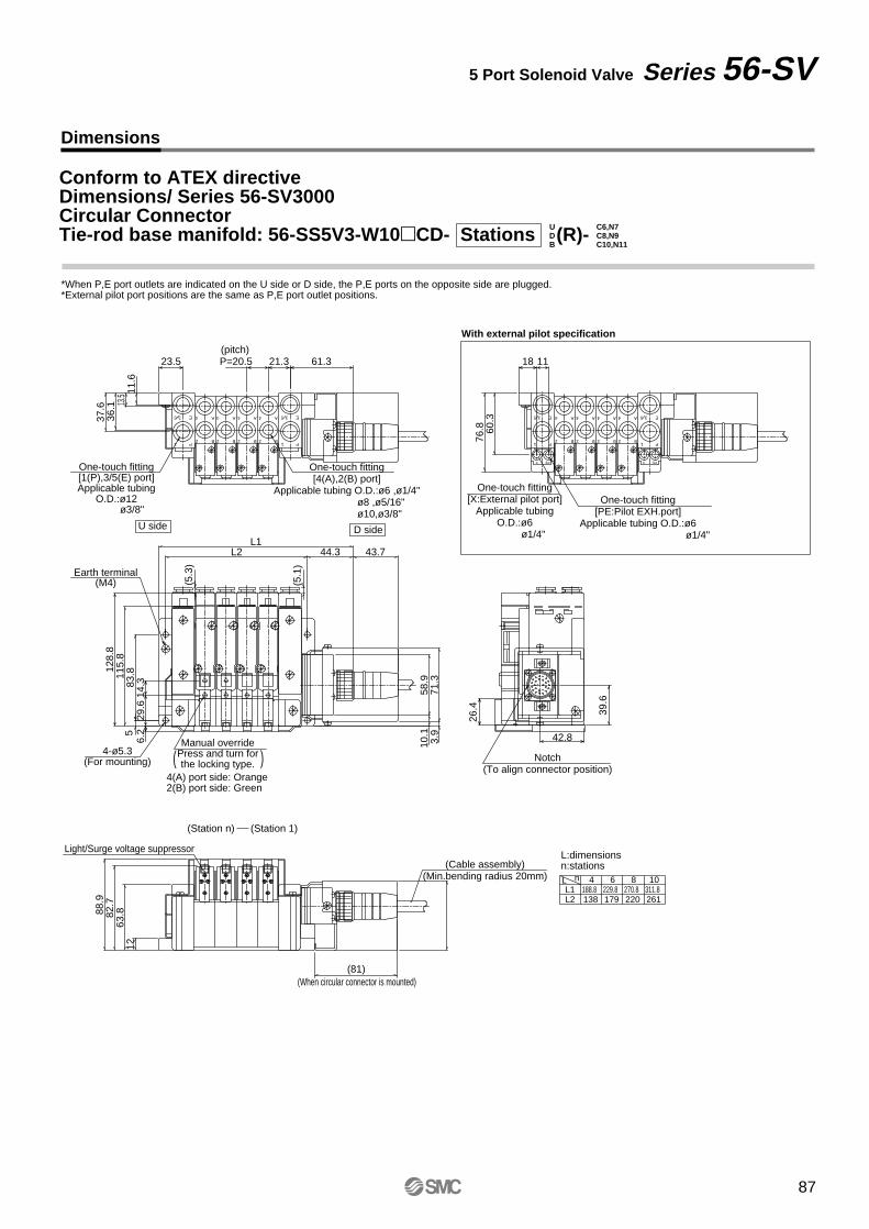
61.3
37.6
11.6
36.1 13
.5
23.5 P=20.5 21.3
One-touch fitting[4(A),2(B) port]
Applicable tubing O.D.:ø6 ,ø1/4" ø8 ,ø5/16" ø10,ø3/8"
One-touch fitting[1(P),3/5(E) port]Applicable tubing
O.D.:ø12 ø3/8"
(pitch)1118
76.8 60
.3One-touch fitting
[PE:Pilot EXH.port]Applicable tubing O.D.:ø6
ø1/4"
One-touch fitting[X:External pilot port]
Applicable tubingO.D.:ø6
ø1/4"
Manual overridePress and turn forthe locking type.
4-ø5.3(For mounting)
83.8
3.9
43.7
71.3
6.2
L144.3L2
10.1
58.9
29.6
14.3
5
128.
811
5.8
4(A) port side: Orange2(B) port side: Green
( )
(5.3
)
(5.1
)
D side U side
Earth terminal(M4)
26.4 39
.6
42.8
Notch(To align connector position)
88.9
(81)
82.7
63.8
12
(Cable assembly)(Min.bending radius 20mm)
Light/Surge voltage suppressor
(When circular connector is mounted)
(Station 1)(Station n)
B C10,N11
Conform to ATEX directiveDimensions/ Series 56-SV3000Circular ConnectorTie-rod base manifold: 56-SS5V3-W10CD- Stations (R)-D
UC8,N9C6,N7
Dimensions
5 Port Solenoid Valve Series 56-SV
*When P,E port outlets are indicated on the U side or D side, the P,E ports on the opposite side are plugged.*External pilot port positions are the same as P,E port outlet positions.
With external pilot specification
261220179138311.8270.8229.8
L2188.8
L:dimensionsn:stationsL n 10864L1
E
1 P
35
B
A
2
4 E
1 P
35
2 B
A4
2 B
A4
2 B
A4 E
1 P
35
B
A
2
4 E
1 P
35
X PE X PE
2
4 A
B 2
4 A
B 2
4 A
B
A
B
A
B
A
B
AB
AB
A
B
12
3
4 5
6
78
9
10
1112
13
1415
1617
18 19
2021
22
23
2425 26
87
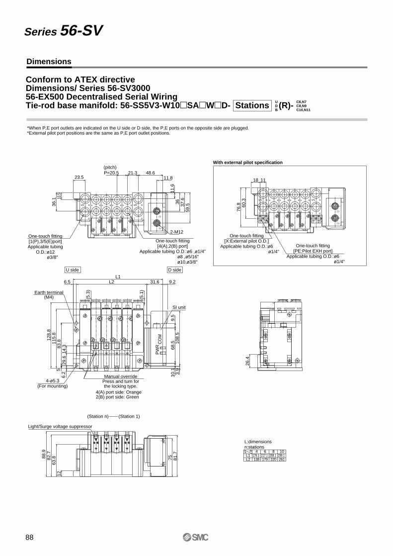
E
1 P
35
B
A
2
4 E
1 P
35
C1
C2
X PE X PE
B2
4 A
B2
4 A
B2
4 A
A
B
A
B
A
B
AB
AB
A
B
E
1 P
35
B
A
2
4 E
1 P
35
C1
C22
4 A
B 2
4 A
B 2
4 A
B
B C10,N11
Conform to ATEX directiveDimensions/ Series 56-SV300056-EX500 Decentralised Serial WiringTie-rod base manifold: 56-SS5V3-W10SAWD- Stations (R)-D
UC8,N9C6,N7
Dimensions
Series 56-SV
*External pilot port positions are the same as P,E port outlet positions.*When P,E port outlets are indicated on the U side or D side, the P,E ports on the opposite side are plugged.
299.1258.1217.1220 261179138
176.1
L:dimensionsn:stations
L2L1
L n 10864
With external pilot specification
59.537
.636
11.6
36.1 13
.5
23.5P=20.5 21.3 48.6
11.8
2-M12
One-touch fitting[4(A),2(B) port]
Applicable tubing O.D.:ø6 ,ø1/4" ø8 ,ø5/16" ø10,ø3/8"
One-touch fitting[1(P),3/5(E)port]Applicable tubing
O.D.:ø12 ø3/8"
(pitch)
1118
76.8 60
.3One-touch fitting
[PE:Pilot EXH port]Applicable tubing O.D.:ø6
ø1/4"
One-touch fitting[X:External pilot O.D.]
Applicable tubing O.D.:ø6 ø1/4"
26.4
3.9
108.
5
9.2L1
31.6
9.5
10.1
68.5
6.5 L2
Manual overridePress and turn forthe locking type.
4(A) port side: Orange2(B) port side: Green
D side U side
SI unit
83.8
6.2
(5.3
)
29.6
14.3
(5.1
)
5
128.
811
5.8
PW
RC
OM
4-ø5.3(For mounting)
Light/Surge voltage suppressor
(Station 1)(Station n)
81.7
88.9
82.7
63.8
12
75
Earth terminal(M4)
88
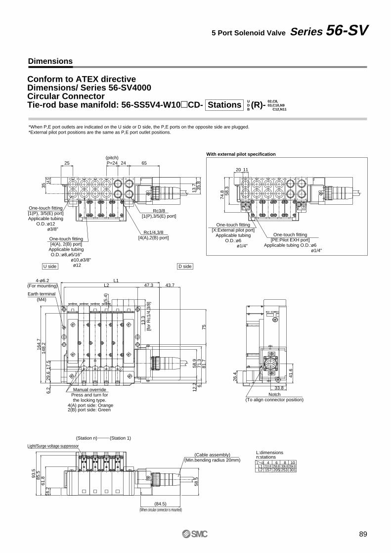
P1
E3/5
P1
E3/5A
B2
4 A
B2
4 A
B2
4 A
B2
4
X PE X PE
12
3
4 5
6
78
9
10
1112
13
1415
1617
18 19
2021
22
23
2425 26
P1
E3/5
P1
E3/5A
B2
4 A
B2
4 A
B2
4 A
B2
4
B
A
B
A
B
A
AB
B
A
AB
4-ø6.2(For mounting)
Earth terminal(M4)
B C12,N11
Conform to ATEX directiveDimensions/ Series 56-SV4000Circular ConnectorTie-rod base manifold: 56-SS5V4-W10CD- Stations (R)-D
U03,C10,N902,C8,
Dimensions
*When P,E port outlets are indicated on the U side or D side, the P,E ports on the opposite side are plugged.*External pilot port positions are the same as P,E port outlet positions.
5 Port Solenoid Valve Series 56-SV
With external pilot specification
6525
35.8
13.735
14.5
P=24 24
Rc3/8[1(P),3/5(E) port]
Rc1/4,3/8[4(A),2(B) port]One-touch fitting
[4(A), 2(B) port]Applicable tubingO.D.:ø8,ø5/16"
ø10,ø3/8" ø12
One-touch fitting[1(P), 3/5(E) port]Applicable tubing
O.D.:ø12 ø3/8"
(pitch)
D side U side
74.8 58
.3
1120
One-touch fitting[PE:Pilot EXH port]
Applicable tubing O.D.:ø6 ø1/4"
One-touch fitting[X:External pilot port]
Applicable tubingO.D.:ø6
ø1/4"
12.2
58.9
43.7
6.2 6
71.3
13.3
L147.3
7581
.7
164.
714
8.2
29.6
17.5
L2
(5.4
)
[for
Rc1
/4,3
/8]
4(A) port side: Orange2(B) port side: Green
Manual overridePress and turn forthe locking type.
26.4 41
.6
33.8Notch
(To align connector position)
93.5
(84.5)
85.5
61.8
16.2
(When circular connector is mounted)
301253205157354.8306.8258.8
L2210.8
L:dimensionsn:stationsL n 10864L1
(Cable assembly)(Min.bending radius 20mm)
(Station 1)(Station n)
Light/Surge voltage suppressor
58.5
89
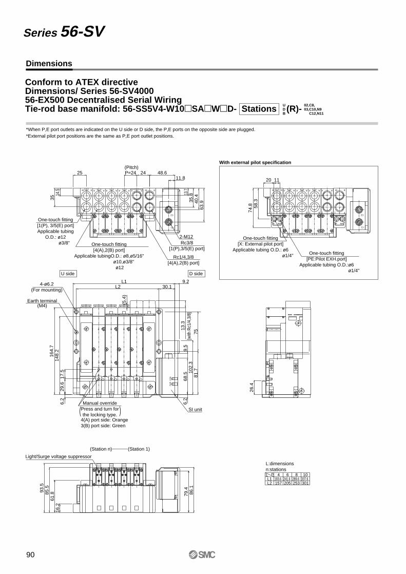
4
2 B
A4
2 B
A4
2 B
A 4
2 B
A
C2
C1
PEXPEX
3/5 E
1 P
3/5 E
1 P
4
2 B
A4
2 B
A4
2 B
A
C2
C1
4
2 B
A3/5 E
1 P
3/5 E
1 P
BA
A
B
BA
A
B
A
B
A
B
PW
RC
OM
35.813
.7
48.611.8
25
63.940
.4
P=24 24
3514
.5
Rc3/8[1(P),3/5(E) port]
Rc1/4,3/8[4(A),2(B) port]
One-touch fitting[4(A),2(B) port]
Applicable tubingO.D.: ø8,ø5/16" ø10,ø3/8"
ø12
One-touch fitting[1(P), 3/5(E) port]Applicable tubing
O.D.: ø12 ø3/8"
2-M12
(Pitch)
D side U side
13.3
75[w
ith R
c1/4
,3/8
]
B C12,N11
Conform to ATEX directiveDimensions/ Series 56-SV400056-EX500 Decentralised Serial WiringTie-rod base manifold: 56-SS5V4-W10SAWD- Stations (R)-D
U03,C10,N902,C8,
Dimensions
Series 56-SV
Earth terminal(M4)
93.5
102.
3
26.4
6.2
6.2
9.2L1
20 11
74.8 58
.3
85.5
86.1
(5.4
)
30.1L2
81.7
9.5
68.5
164.
714
8.2
17.5
29.6
16.2
79.4
61.8
337.6289.6241.6193.6301253205157L2
L:dimensionsn:stationsL n 10864L1
One-touch fitting[PE:Pilot EXH.port]
Applicable tubing O.D.:ø6 ø1/4"
4(A) port side: Orange3(B) port side: Green
4-ø6.2(For mounting)
SI unitManual override
Press and turn forthe locking type.
(Station 1)(Station n)
Light/Surge voltage suppressor
With external pilot specification
One-touch fitting[X: External pilot port]
Applicable tubing O.D.: ø6 ø1/4"
*External pilot port positions are the same as P,E port outlet positions.*When P,E port outlets are indicated on the U side or D side, the P,E ports on the opposite side are plugged.
( )
90

91
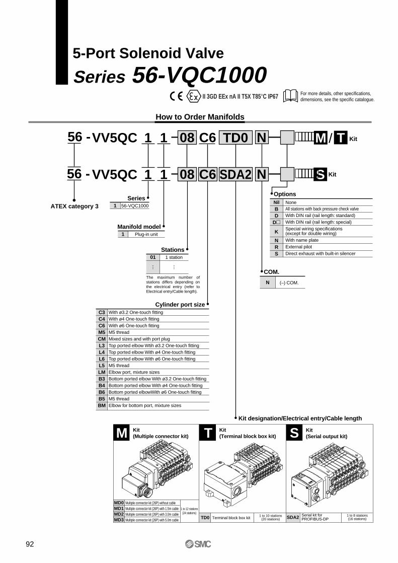
For more details, other specifications, dimensions, see the specific catalogue.
5-Port Solenoid Valve
Series 56-VQC1000
56 -
ATEX category 3
VV5QC 1 1 08 C6
1 56-VQC1000
Series
TD0
1 Plug-in unit
Manifold model
Stations
VV5QC 1 1 08 C6 SDA2Options
COM.
Kit designation/Electrical entry/Cable length
Cylinder port size
F T⋅⋅⋅⋅⋅⋅ Kit/LM
S⋅⋅⋅⋅⋅⋅ Kit
Nil NoneAll stations with back pressure check valve With DIN rail (rail length: standard)With DIN rail (rail length: special)
Special wiring specifications (except for double wiring) With name plateExternal pilot Direct exhaust with built-in silencer
BD
D
K
NRS
(–) COM.N
01 1 station
The maximum number of stations differs depending on the electrical entry (refer to Electrical entry/Cable length).
C3C4C6M5CML3L4L6L5LMB3B4B6B5BM
With ø3.2 One-touch fittingWith ø4 One-touch fittingWith ø6 One-touch fittingM5 threadMixed sizes and with port plugTop ported elbow Wtih ø3.2 One-touch fittingTop ported elbow With ø4 One-touch fittingTop ported elbow With ø6 One-touch fittingM5 threadElbow port, mixture sizesBottom ported elbow With ø3.2 One-touch fittingBottom ported elbow With ø4 One-touch fittingBottom ported elbowWith ø6 One-touch fittingM5 threadElbow for bottom port, mixture sizes
56 -
TD0 Terminal block box kit 1 to 10 stations(20 stations) SDA2 Serial kit for
PROFIBUS-DP1 to 8 stations(16 stations)
Multiple connector kit (26P) without cableMultiple connector kit (26P) with 1.5m cableMultiple connector kit (26P) with 3.0m cableMultiple connector kit (26P) with 5.0m cable
MD0MD1MD2MD3
1 to 12 stations(24 stations)
T Kit(Terminal block box kit) S Kit
(Serial output kit)M Kit(Multiple connector kit)
How to Order Manifolds
II 3GD EEx nA II T5X T85°C IP67
EX500
series
N
N
92

VQC 1 1 0 5
Manual overrideNil: Non-locking
push type(Slotted)
B: Locking type(Slotted)
C: Locking type(Manual)
D: Slide locking type(Manual)
0
Series 56-VQC Base-Mounted Type Plug-in Unit
How to Order Valves
1 56-VQC1000
Series
Type of actuation
Coil voltage
Seal type
Function2-position single
2-position double (metal)
2-position double (rubber)
3-position closed centre
3-position exhaust centre
3-position pressure centre
1
4-position dual 3-port valve(A)
4-position dual 3-port valve(B)
4-position dual 3-port valve(C)
A
B
C
2
3
4
5
N.C N.C
N.O N.O
N.C N.O
Note)
Note)
Note)
Note) For rubber seal type only.
Metal sealRubber seal
01
24VDC5
Standard typeExternal pilot
NilR5
(R1)3
(R2)1
(P)
5(R1)
3(R2)1
(P)
5(R1)
3(R2)1
(P)
5(R1)
3(R2)1
(P)
(A)4
(B)2
(A)4
(B)2
(A)4
(B)2
(A)4
(B)2
5(R1)
3(R2)
1(P)
(A)4
(B)2
5(R1)
3(R2)
1(P)
5(R1)
3(R2)
1(P)
5(R1)
3(R2)
1(P)
5(R1)
3(R2)
1(P)
(A)4
(B)2
(A)4
(B)2
(A)4
(B)2
(A)4
(B)2
Note) ''56-'' solenoid valve should be installed in ''56-VV5QC11'' manifold.Power consumption when starting is 1W, when maintaining 0.35W.
56 -
ATEX category 3
93
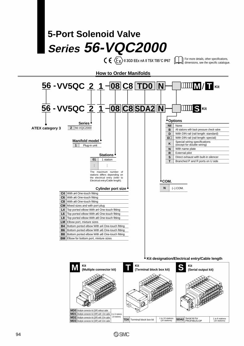
For more details, other specifications, dimensions, see the specific catalogue.
5-Port Solenoid Valve
Series 56-VQC2000
56 -
ATEX category 3
VV5QC 2 1 08 C8
2 56-VQC2000
Series
TD0
1 Plug-in unit
Manifold model
Stations
VV5QC 2 1 08 C8 SDA2Options
COM.
Kit designation/Electrical entry/Cable length
Cylinder port size
F T⋅⋅⋅⋅⋅⋅ Kit/LM
S⋅⋅⋅⋅⋅⋅ Kit
(–) COM.N
01 1 station
The maximum number of stations differs depending on the electrical entry (refer to Electrical entry/Cable length).
C4C6C8CML4L6L8LMB4B6B8BM
With ø4 One-touch fittingWith ø6 One-touch fittingWith ø8 One-touch fittingMixed sizes and with port plugTop ported elbow With ø4 One-touch fittingTop ported elbow With ø6 One-touch fittingTop ported elbow With ø8 One-touch fittingElbow port, mixture sizesBottom ported elbow With ø4 One-touch fittingBottom ported elbow With ø6 One-touch fittingBottom ported elbow With ø8 One-touch fittingElbow for bottom port, mixture sizes
56 -
TD0 Terminal block box kit 1 to 10 stations(20 stations) SDA2 Serial kit for
PROFIBUS-DP1 to 8 stations(16 stations)
Multiple connector kit (26P) without cableMultiple connector kit (26P) with 1.5m cableMultiple connector kit (26P) with 3.0m cableMultiple connector kit (26P) with 5.0m cable
MD0MD1MD2MD3
1 to 12 stations(24 stations)
T Kit(Terminal block box kit) S Kit
(Serial output kit)M Kit(Multiple connector kit)
How to Order Manifolds
Nil NoneAll stations with back pressure check valveWith DIN rail (rail length: standard)With DIN rail (rail length: special)Special wiring specifications (except for double wiring) With name plateExternal pilotDirect exhaust with built-in silencerBranched P and R ports on U side
BD
D
K
NRST
N
N
EX500
series
II 3GD EEx nA II T5X T85°C IP67
94
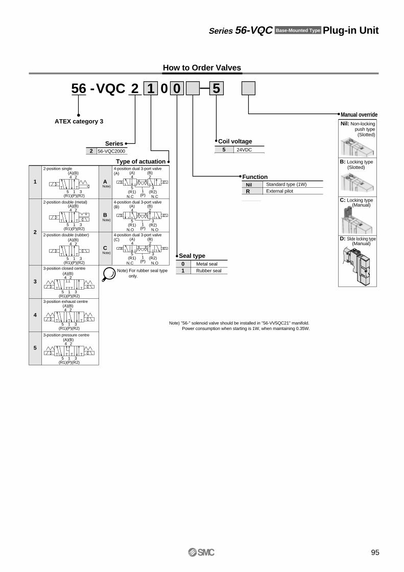
VQC 2 1 0 5
Manual overrideNil: Non-locking
push type(Slotted)
B: Locking type(Slotted)
C: Locking type(Manual)
D: Slide locking type(Manual)
0
Series 56-VQC Base-Mounted Type Plug-in Unit
How to Order Valves
2 56-VQC2000
Series
Type of actuation
Coil voltage
Seal type
Function2-position single
2-position double (metal)
2-position double (rubber)
3-position closed centre
3-position exhaust centre
3-position pressure centre
1
4-position dual 3-port valve(A)
4-position dual 3-port valve(B)
4-position dual 3-port valve(C)
A
B
C
2
3
4
5
N.C N.C
N.O N.O
N.C N.O
Note)
Note)
Note)
Note) For rubber seal type only.
Metal sealRubber seal
01
24VDC5
5(R1)
3(R2)
1(P)
5(R1)
3(R2)1
(P)
5(R1)
3(R2)1
(P)
5(R1)
3(R2)1
(P)
(A)4
(B)2
(A)4
(B)2
(A)4
(B)2
(A)4
(B)2
5(R1)
3(R2)
1(P)
(A)4
(B)2
5(R1)
3(R2)
1(P)
5(R1)
3(R2)
1(P)
5(R1)
3(R2)
1(P)
5(R1)
3(R2)
1(P)
(A)4
(B)2
(A)4
(B)2
(A)4
(B)2
(A)4
(B)2
Note) ''56-'' solenoid valve should be installed in ''56-VV5QC21'' manifold.Power consumption when starting is 1W, when maintaining 0.35W.
56 -
ATEX category 3
Standard type (1W)External pilot
NilR
95
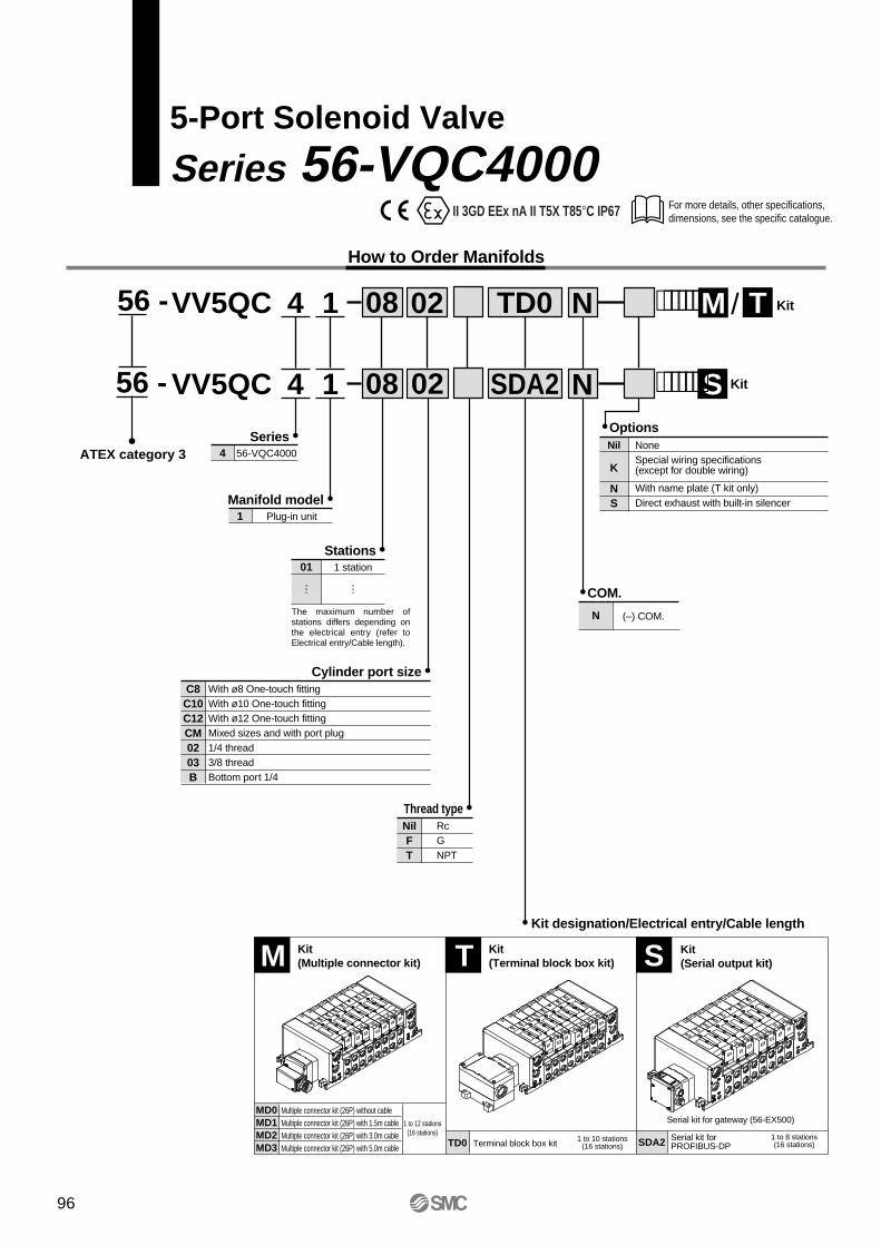
For more details, other specifications, dimensions, see the specific catalogue.
5-Port Solenoid Valve
Series 56-VQC4000
56 -
ATEX category 3
VV5QC 4 1 08
4 56-VQC4000
Series
TD0
1 Plug-in unit
Manifold model
Stations
VV5QC 4 1 08 02 SDA2Options
COM.
Kit designation/Electrical entry/Cable length
Cylinder port size
F T⋅⋅⋅⋅⋅⋅ Kit/LM
S⋅⋅⋅⋅⋅⋅ Kit
(–) COM.N
01 1 station
The maximum number of stations differs depending on the electrical entry (refer to Electrical entry/Cable length).
C8C10C12CM0203B
With ø8 One-touch fittingWith ø10 One-touch fittingWith ø12 One-touch fittingMixed sizes and with port plug1/4 thread3/8 threadBottom port 1/4
56 -
TD0 Terminal block box kit 1 to 10 stations(16 stations) SDA2 Serial kit for
PROFIBUS-DP1 to 8 stations(16 stations)
Multiple connector kit (26P) without cableMultiple connector kit (26P) with 1.5m cableMultiple connector kit (26P) with 3.0m cableMultiple connector kit (26P) with 5.0m cable
MD0MD1MD2MD3
1 to 12 stations(16 stations)
T Kit(Terminal block box kit) S Kit
(Serial output kit)M Kit(Multiple connector kit)
How to Order Manifolds
Serial kit for gateway (56-EX500)
Nil NoneSpecial wiring specifications (except for double wiring)
With name plate (T kit only)Direct exhaust with built-in silencer
K
NS
02
Thread typeNilFT
RcGNPT
N
N
EX500
series
II 3GD EEx nA II T5X T85°C IP67
96
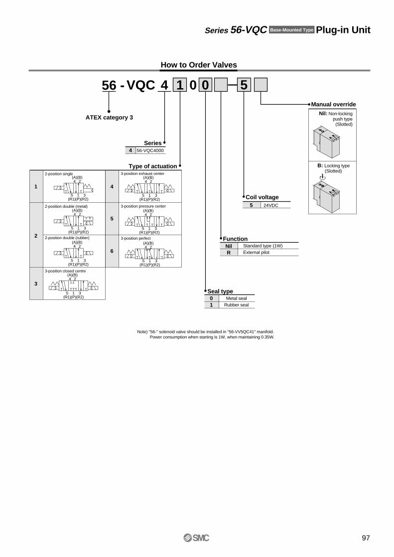
Series 56-VQC Base-Mounted Type Plug-in Unit
56 -
ATEX category 3
Note) ''56-'' solenoid valve should be installed in ''56-VV5QC41'' manifold.Power consumption when starting is 1W, when maintaining 0.35W.
4 56-VQC4000
Series
Type of actuation
VQC 4 1 0 5
Coil voltage
Manual override
Seal type
Function
2-position single
2-position double (metal)
2-position double (rubber)
3-position closed centre
1
2
3
24VDC5
3-position exhaust center
3-position pressure center
3-position perfect
4
5
6
0
How to Order Valves
Nil: Non-lockingpush type
(Slotted)
B: Locking type(Slotted)
Standard type (1W)External pilot
NilR
Metal sealRubber seal
01
5(R1)
3(R2)
1(P)
5(R1)
3(R2)
1(P)
5(R1)
3(R2)
1(P)
5(R1)
3(R2)
1(P)
5(R1)
3(R2)
1(P)
5(R1)
3(R2)
1(P)
5(R1)
3(R2)
1(P)
(A)4
(B)2
(A)4
(B)2
(A)4
(B)2
(A)4
(B)2
(A)4
(B)2
(A)4
(B)2
(A)4
(B)2
97
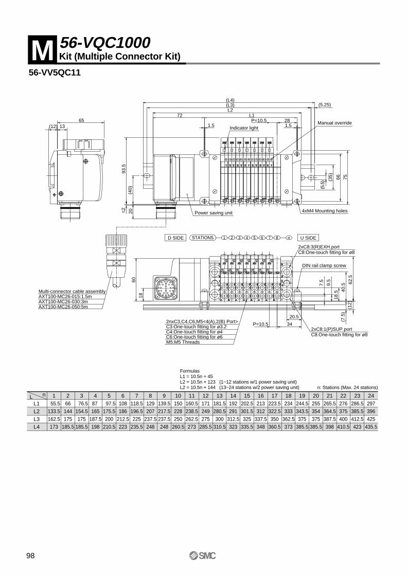
56-VV5QC11
nLL1L2L3L4
1 55.5133.5162.5173
266
144175
185.5
3 76.5154.5175
185.5
487 165
187.5198
5 97.5175.5200
210.5
6108186
212.5223
7118.5196.5225
235.5
8129207
237.5248
9139.5217.5237.5248
10150228250
260.5
11160.5238.5262.5273
12171249275
285.5
13181.5280.5300
310.5
14192291
312.5323
15202.5301.5325
335.5
16213312
337.5348
17223.5322.5350
360.5
18234333
362.5373
19244.5343.5375
385.5
20255354375
385.5
21265.5364.5387.5398
22276375400
410.5
23286.5385.5412.5423
24297396425
435.5
FormulasL1 = 10.5n + 45L2 = 10.5n + 123 (1~12 stations w/1 power saving unit)L2 = 10.5n + 144 (13~24 stations w/2 power saving unit) n: Stations (Max. 24 stations)
M 56-VQC1000Kit (Multiple Connector Kit)
1.5P=10.5
1.5
L1L2
(L3)(L4)
28
(5.5
) (35)
93.5
=2
(12) 13
9.5
20.5
34P=10.5
65
60
66 7562
.5
7.5
18.5
(12)
(7.5
)40
.5
72
18
20(4
0)
(5.25)
Multi-connector cable assemblyAXT100-MC26-015:1.5mAXT100-MC26-030:3mAXT100-MC26-050:5m
2nxC3,C4,C6,M5<4(A),2(B) Port>C3:One-touch fitting for ø3.2C4:One-touch fitting for ø4C6:One-touch fitting for ø6M5:M5 Threads
2xC8:1(P)SUP.portC8:One-touch fitting for ø8
DIN rail clamp screw
2xC8:3(R)EXH.portC8:One-touch fitting for ø8
Power saving unit 4xM4 Mounting holes
Indicator lightManual override
n1 2 3 4 5 6 7 8 U SIDED SIDE STATIONS
98
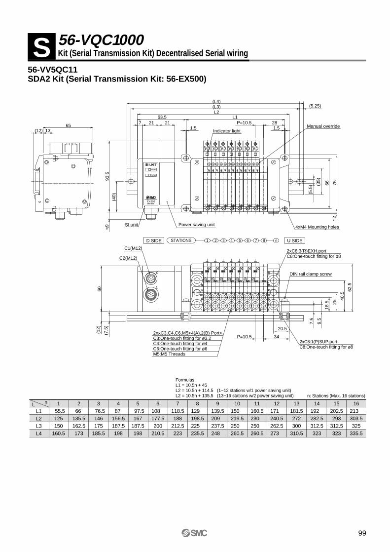
56-VV5QC11SDA2 Kit (Serial Transmission Kit: 56-EX500)
nLL1L2L3L4
1 55.5125150
160.5
266
135.5162.5173
3 76.5146175
185.5
487
156.5187.5198
5 97.5167
187.5198
6108 177.5200
210.5
7118.5188
212.5223
8129 198.5225 235.5
9139.5209 237.5248
10150 219.5250 260.5
11160.5230 250 260.5
12171 240.5262.5273
13181.5272300
310.5
14192 282.5312.5323
15202.5293
312.5323
16213 303.5325
335.5
S 56-VQC1000Kit (Serial Transmission Kit) Decentralised Serial wiring
FormulasL1 = 10.5n + 45L2 = 10.5n + 114.5 (1~12 stations w/1 power saving unit)L2 = 10.5n + 135.5 (13~16 stations w/2 power saving unit) n: Stations (Max. 16 stations)
9.5
20.5
34P=10.5
62.5
7.5
18.5
40.5
1.5P=10.5
Indicator light1.5
L1
(L3)(L4)
28
(5.5
) (35)93
.5
66 75
(12) 1365 7 21
63.5L2
(5.25)
(40)
=2
=9
(7.5
)
(12)
60
25
21
2nxC3,C4,C6,M5<4(A),2(B) Port>C3:One-touch fitting for ø3.2C4:One-touch fitting for ø4 C6:One-touch fitting for ø6M5:M5 Threads
2xC8:1(P)SUP.portC8:One-touch fitting for ø8
DIN rail clamp screw
2xC8:3(R)EXH.portC8:One-touch fitting for ø8
SI unit
PWR
COM
EX500series
0
1
C2(M12)
C1(M12)
Power saving unit 4xM4 Mounting holes
Manual override
n1 2 3 4 5 6 7 8 U SIDED SIDE STATIONS
99
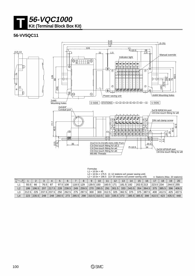
56-VV5QC11
nLL1L2L3L4
1 55.5186
212.5223
266
196.5225
235.5
3 76.5207
237.5248
487
217.5237.5248
5 97.5228250
260.5
6108 238.5262.5273
7118.5249275
285.5
8129 259.5287.5298
9139.5270300
310.5
10150 280.5300
310.5
11160.5291
312.5323
12171 301.5325
335.5
13181.5333
362.5373
14192 343.5375
385.5
15202.5354375
385.5
16213 364.5387.5398
17223.5375400
410.5
18234 385.5412.5423
19244.5396425
435.5
20255 406.5437.5448
T 56-VQC1000Kit (Terminal Block Box Kit)
FormulasL1 = 10.5n + 45L2 = 10.5n + 175.5 (1~12 stations w/1 power saving unit)L2 = 10.5n + 196.5 (13~20 stations w/2 power saving unit) n: Stations (Max. 20 stations)
93.5
21
(40)
(12)
(7.5
)
25
7.7
124
(59)
126
80
(5.25)
40.5
35
77.7
45.5
18.7
62.5
P=10.5 3420.5
9.5
71
L2
13(12)
7566(35)
(5.5
)
28
(L4)(L3)
L1
1.5P=10.5
1.5Manual override
2xM5Mounting holes
2xG3/4"Conduit port
U side
D side
STATIONSD SIDE U SIDE87654321 n
Indicator light
4xM4 Mounting holesPower saving unit
2xC8:3(R)EXH.portC8:One-touch fitting for ø8
DIN rail clamp screw
2xC8:1(P)SUP.portC8:One-touch fitting for ø8
2nxC3,C4,C6,M5<4(A),2(B) Port>C3:One-touch fitting for ø3.2C4:One-touch fitting for ø4C6:One-touch fitting for ø6M5:M5 Threads
ABABABABABABA
A A A A A A A A
B B B B B B B B
1 1
P
12
X
3
R
P
12
X
3
R
100

56-VV5QC21
nLL1L2L3L4
1 73 147.5175
185.5
289
163.5187.5198
3 105179.5200
210.5
4121
195.5225
235.5
5 137211.5237.5248
6153
227.5250
260.5
7169
243.5275
285.5
8185
259.5287.5298
9201
275.5300
310.5
10217
291.5312.5323
11233
307.5337.5348
12249 323.5350
360.5
13265 360.5387.5398
14281
376.5400
410.5
15297
392.5412.5423
16313
408.5437.5448
17329 424.5450
460.5
18345
440.5462.5473
19361
456.5487.5498
20377 472.5500
510.5
21393 488.5512.5523
22409 504.5525
535.5
23425 520.5550
560.5
24441 536.5562.5573
FormulasL1 = 16n + 57L2 = 16n + 131.5 (1~12 stations w/1 power saving unit)L2 = 16n + 152.5 (13~24 stations w/2 power saving unit) n: Stations (Max. 24 stations)
M 56-VQC2000Kit (Multiple Connector Kit)
2nxC4,C6,C8<4(A),2(B) Port>C4:One-touch fitting for ø4C6:One-touch fitting for ø6C8:One-touch fitting for ø8
2xC10:1(P)SUP.portC10:One-touch fitting for ø10
DIN rail clamp screw
2xC10:3(R)EXH.portC10:One-touch fitting for ø10
4xM5 Mounting holes
Power saving unit
Indicator light
Manual override
Multi-connector cable assemblyAXT100-MC26-015:1.5mAXT100-MC26-030:3mAXT100-MC26-050:5m
11
38.5P=1634.5
L1
L2
13.5
49.5
25
45P=16
1376.5
(L3)
(L4)
(5.5
)
(35) 80
105.
5=
5.5
127
=3.
5(7
.5)
(12)
60
(12)
6818
10
25
76.5
(53.
5)21
n1 2 3 4 5 6 7 8 U SIDED SIDE STATIONS
101
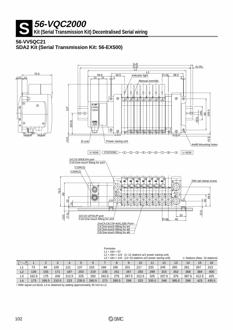
nLL1L2L3L4
173 139
162.5173
289 155175
185.5
3105 171200
210.5
4121 187
212.5223
5137 203225
235.5
6153 219250
260.5
7169 235
262.5273
8185 251275
285.5
9201 267
287.5298
10217 283
312.5323
11233 299325
335.5
12249 315
337.5348
13265 352375
385.5
14281 368
387.5398
15297 384
412.5423
16313 400425
435.5∗ With signal cut block, L4 is obtained by adding approximately 30 mm to L2.
56-VV5QC21SDA2 Kit (Serial Transmission Kit: 56-EX500)
S 56-VQC2000Kit (Serial Transmission Kit) Decentralised Serial wiring
FormulasL1 = 16n + 57L2 = 16n + 123 (1~12 stations w/1 power saving unit)L2 = 16n + 144 (13~16 stations w/2 power saving unit) n: Stations (Max. 16 stations)
2nxC4,C6,C8<4(A),2(B) Port>C4:One-touch fitting for ø4C6:One-touch fitting for ø6C8:One-touch fitting for ø8
2xC10:1(P)SUP.portC10:One-touch fitting for ø10
DIN rail clamp screw
C1(M12)
C2(M12)
SI unit
PWR
COM
EX500series
0
1
2xC10:3(R)EXH.portC10:One-touch fitting for ø10
4xM5 Mounting holesPower saving unit
Indicator light
Manual override11
38.5P=1634.5L1
1376.5
(L3)(L4)
(5.5
)
(35)
80 105.
5=
5.5
127
=3.
5
(12)59.5
L2(5
3.5)
49.5
2545P=16
1025
6076
.5
(5.25)(7
.5)
(12) 13
.530
21 21
n1 2 3 4 5 6 7 8 U SIDED SIDE STATIONS
102
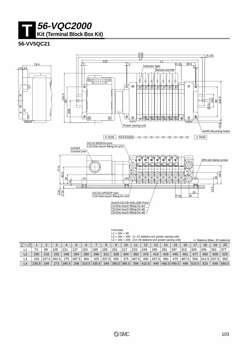
nLL1L2L3L4
173 200225
235.5
289 216
237.5248
3105 232
262.5273
4121 248275
285.5
5137 264
287.5298
6153 280300
310.5
7169 296325
335.5
8185 312
337.5348
9201 328350
360.5
10217 344375
385.5
11233 360
387.5398
12249 376400
410.5
13265 413
437.5448
14281 429450
460.5
15297 445475
485.5
16313 461
487.5498
17329 477500
510.5
18345 493
512.5523
19361 509
537.5548
20377 525550
560.5
56-VV5QC21
T 56-VQC2000Kit (Terminal Block Box Kit)
FormulasL1 = 16n + 45L2 = 16n + 184 (1~12 stations w/1 power saving unit)L2 = 16n + 205 (13~20 stations w/2 power saving unit) n: Stations (Max. 20 stations)
2nxC4,C6,C8<4(A),2(B) Port>C4:One-touch fitting for ø4C6:One-touch fitting for ø6C8:One-touch fitting for ø8
2xC10:1(P)SUP.portC10:One-touch fitting for ø10
2xC10:3(R)EXH.portC10:One-touch fitting for ø10
Power saving unit
U SIDED SIDE STATIONS n1 2 83 4 5 6 7
D side
U side
2xG3/4Conduit port
DIN rail clamp screw
4xM5 Mounting holes
Manual overrideIndicator light 1
1 38.5P=16L1
(5.5
) (35)
80 105.
5=
5.5
(12) 1376.5
(L3)(L4)
L2
780
49.5
2545P=16
1025
77.5
45.5
(7.5
)(1
2)
(59)
132.
5120
3013
.5
(5.25)
103
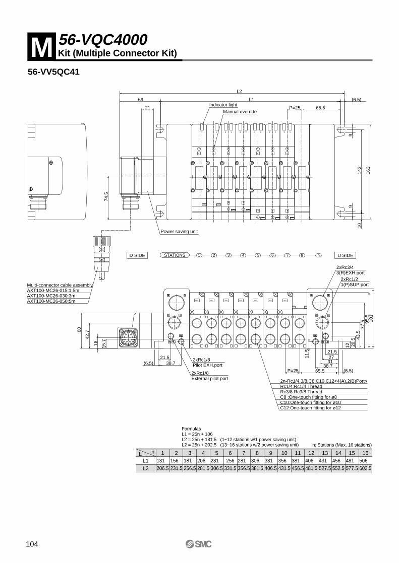
56-VV5QC41
nLL1L2
1131 206.5
2156 231.5
3181 256.5
4206 281.5
5231 306.5
6256
331.5
7281 356.5
8306 381.5
9331 406.5
10356 431.5
11381 456.5
12406 481.5
13431 527.5
14456 552.5
15481 577.5
16506 602.5
FormulasL1 = 25n + 106L2 = 25n + 181.5 (1~12 stations w/1 power saving unit)L2 = 25n + 202.5 (13~16 stations w/2 power saving unit) n: Stations (Max. 16 stations)
M 56-VQC4000Kit (Multiple Connector Kit)
Multi-connector cable assemblyAXT100-MC26-015:1.5mAXT100-MC26-030:3mAXT100-MC26-050:5m SMC SMCSMCSMCSMCSMCSMC
A A
B A
A
B
A
B
A
B
A
B
B AB A
A
B
B AB AAA
2n-Rc1/4,3/8,C8,C10,C12<4(A),2(B)Port>Rc1/4:Rc1/4 ThreadRc3/8:Rc3/8 ThreadC8 :One-touch fitting for ø8C10:One-touch fitting for ø10C12:One-touch fitting for ø12
2xRc1/8Pilot EXH.port
2xRc1/8External pilot port
2xRc1/21(P)SUP.port
2xRc3/43(R)EXH.port
Power saving unit
Indicator light
Manual override
12 20.5 43
.577
.5 95.5
P=25 65.5
(6.5)
143
9
163
9
L115
.774
.5
60
101
69
L218
42.7
1038.7(6.5)
21.5 2731
65.5 (6.5)P=25
21
21.5
38.7
11.5
n1 2 3 4 5 6 7 8 U SIDED SIDE STATIONS
104
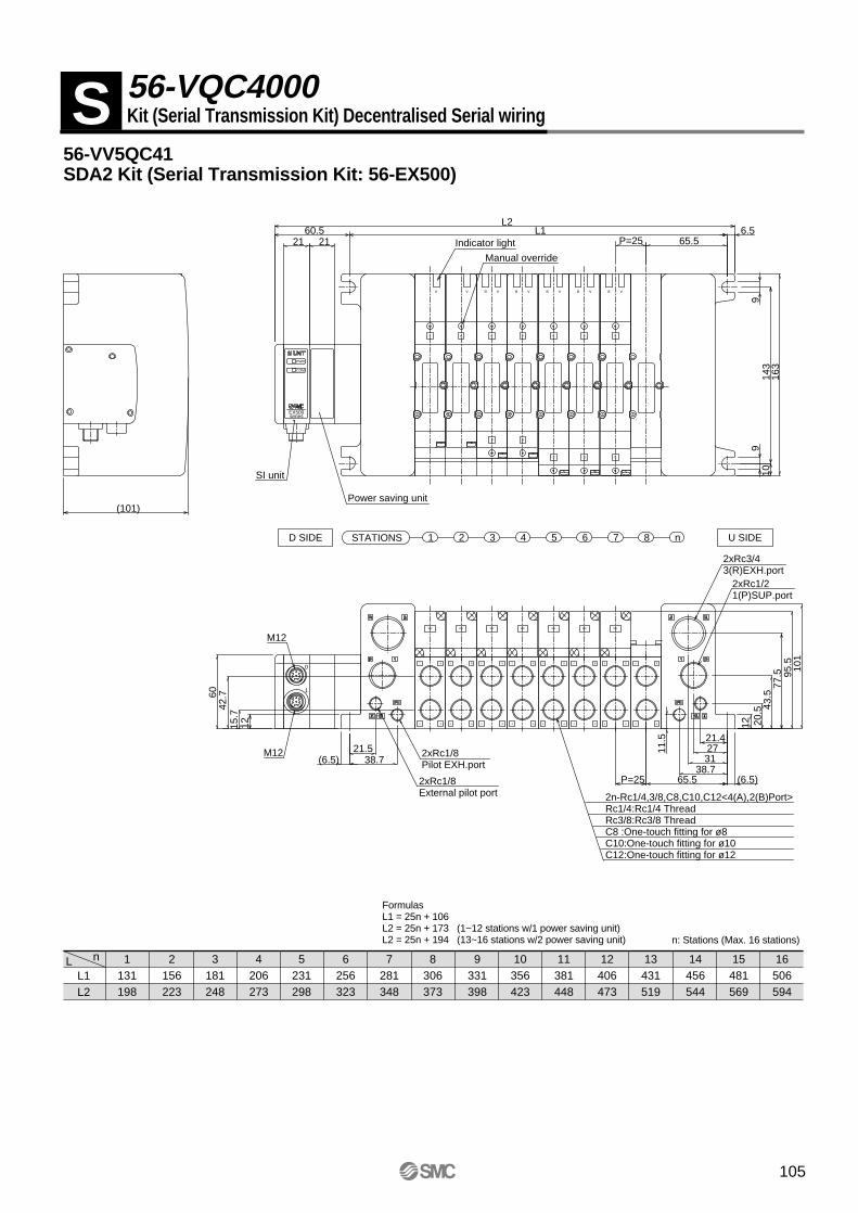
56-VV5QC41SDA2 Kit (Serial Transmission Kit: 56-EX500)
nLL1L2
1131198
2156223
3181248
4206273
5231298
6256323
7281348
8306373
9331398
10356423
11381448
12406473
13431519
14456544
15481569
16506594
FormulasL1 = 25n + 106L2 = 25n + 173 (1~12 stations w/1 power saving unit)L2 = 25n + 194 (13~16 stations w/2 power saving unit) n: Stations (Max. 16 stations)
S 56-VQC4000Kit (Serial Transmission Kit) Decentralised Serial wiring
A
A
A
A
A
B
B A
A
B
B A
A
B
B A
A
B
B A
A
B
B A
2 B
4 A
2 B
4 A
2 B
4 A
2 B
4 A
2 B
4 A
2 B
4 A
2 B
4 A
2 B
4 A
SMC SMC SMC SMC SMC SMC SMC
2n-Rc1/4,3/8,C8,C10,C12<4(A),2(B)Port>Rc1/4:Rc1/4 ThreadRc3/8:Rc3/8 ThreadC8 :One-touch fitting for ø8C10:One-touch fitting for ø10C12:One-touch fitting for ø12
2xRc1/8Pilot EXH.port
2xRc1/8External pilot port
2xRc1/21(P)SUP.port
2xRc3/43(R)EXH.port
Indicator light
Manual override
U SIDED SIDE STATIONS 1 2 3 4 5 6 7 8 n
Power saving unit
SI unit
M12
M12
PWR
COM
EX500series
0
1
12 20.5 43
.577
.5 95.5 101
38.7(6.5)21.5 27
31
65.5 (6.5)P=25
P=25 65.56.5
143
9
163
910
(101)
L11215
.742
.760
60.5L2
21 21
21.4
38.7
11.5
105
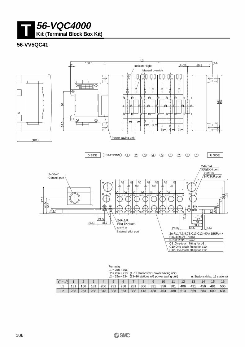
56-VV5QC41
nLL1L2
1131238
2156263
3181288
4206313
5231338
6256363
7281388
8306413
9331438
10356463
11381488
12406513
13431559
14456584
15481609
16506634
T 56-VQC4000Kit (Terminal Block Box Kit)
FormulasL1 = 25n + 106L2 = 25n + 213 (1~12 stations w/1 power saving unit)L2 = 25n + 234 (13~16 stations w/2 power saving unit) n: Stations (Max. 16 stations)
A
A
A
A
A
B
B A
A
B
B A
A
B
B A
A
B
B A
A
B
B A
2 B
4 A
2 B
4 A
2 B
4 A
2 B
4 A
2 B
4 A
2 B
4 A
2 B
4 A
SMC SMC SMC SMC SMC SMC SMC
2n-Rc1/4,3/8,C8,C10,C12<4(A),2(B)Port>Rc1/4:Rc1/4 ThreadRc3/8:Rc3/8 ThreadC8 :One-touch fitting for ø8C10:One-touch fitting for ø10C12:One-touch fitting for ø12
2xRc1/8Pilot EXH.port
2xRc1/8External pilot port
2xRc1/21(P)SUP.port
2xRc3/43(R)EXH.port
Indicator light
Manual override
D side
U side
2 B
4 A
2xG3/4"Conduit port
U SIDED SIDE STATIONS 1 2 3 4 5 6 7 8 n
Power saving unit
12 20.5 43
.577
.5 95.5
101
38.7(6.5)21.5 27
31
65.5 (6.5)P=25
6.5L1
1215.742
.745
.577
.5
8034
.5
(101)
7100.5
L2
910
143
163
9
65.5P=25
21.4
38.7
11.5
106

107
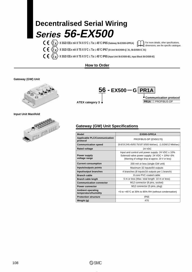
For more details, other specifications, dimensions, see the specific catalogue.
Decentralised Serial Wiring
Series 56-EX500
56 -
ATEX category 3
How to Order
Input Unit Manifold
Model
PROFIBUS-DP (EN50170)
(9.6/19.2/45.45/93.75/187.5/500 kbit/sec), (1.5/3/6/12 Mbit/sec)
Input and control unit power supply: 24 VDC ± 10%Solenoid valve power supply: 24 VDC + 10%/–5%
(Warning of voltage drop at approx. 20 V or less)
24 VDC
200 mA or less (single GW unit)
Maximum 32 inputs/64 outputs
8 core PVC coated cable
5 m or less (Max. total length: 10 m or less)
M12 connector (8 pins, socket)
M12 connector (5 pins, plug)
IP65
470
EX500-GPR1A
Rated voltage
Power supply voltage range
Input/output branches
Ambient operating temperature/humidity
Current consumption
Inputs/outputs points
Branch cable
Branch cable length
Communication connector
Power connector
Protection structure
Weight (g)
Communication speed
Applicable PLC/Communication protocol
Gateway (GW) Unit Specifications
Communication protocolPR1A PROFIBUS-DP
EX500 G PR1A
Gateway (GW) Unit
+5 to +45°C at 35% to 85% RH (without condensation)
4 branches (8 inputs/16 outputs per 1 branch)
II 3GD EEx nA II T4 X 5°C ≤ Ta ≤ 45°C IP65 (Gateway 56-EX500-GPR1A)
II 3GD EEx nA II T5 X 5°C ≤ Ta ≤ 45°C IP67 (SI Unit 56-EX500-Q01, 56-EX500-S01)
II 3GD EEx nA II T5 X 5°C ≤ Ta ≤ 45°C IP65 (Input Unit 56-EX500-IB1, Input Block 56-EX500-IE)
108
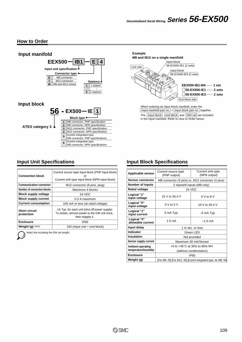
Series 56-EX500Decentralised Serial Wiring
When ordering an input block manifold, enter the Input manifold part no. + Input block part no. together.
The input block , end block and DIN rail are included in the input manifold. Refer to How to Order below.
Input Unit Specifications
Connection block
Short circuit protection
Communication connector
Number of connection blocks
Block supply voltage
Block supply current
Current consumption
Enclosure
Weight (g)
Current source type input block (PNP input block)or
Current sink type input block (NPN input block)
1A Typ. for each unit (shut off power supply)To restart, remove power to the GW unit once,
then reapply it.
M12 connector (8 pins, plug)
Maximum 4 blocks
24 VDC
0.3 A maximum
100 mA or less (at rated voltage)
IP65
100 (Input unit + end block)
Input Block Specifications
Applicable sensor
Sensor connector
Number of inputs
Rated voltage
M8 connector (3 pins) or, M12 connector (4 pins)
2 inputs/8 inputs (M8 only)
24 VDC
Note)
Note) Not including the DIN rail weight.
How to Order
Input manifold
Input block
Example
EX500 IE 1
1234
5
6
Block typeM8 connector, PNP specificationM8 connector, NPN specificationM12 connector, PNP specificationM12 connector, NPN specification8-point integrated type, M8 connector, PNP specifications8-point integrated type, M8 connector, NPN specifications
EEX500 IB1
1
4
Stations1 station
4 stations
E 4
……
ETM
Connector typeM8 connector
M12 connectorM8 and M12 mixed
Input unit specification
M8 and M12 on a single manifold
EEX500-IB1-M4 • • • • • • • 1 set
∗ 56-EX500-IE1 • • • • • • • 2 sets
∗ 56-EX500-IE3 • • • • • • • 2 sets
Unit sideInput block56-EX500-IE3 (2 sets)
Input block56-EX500-IE1 (2 sets)
End block side
56 -
ATEX category 3
Input delay
Indicator
Insulation
Sensor supply current
Enclosure
Weight (g)
1 m sec. or less
Green LED
Not provided
Maximum 30 mA/Sensor
+5 to +45°C at 35% to 85% RH
(without condensation)
IP65
[For M8: 20] [For M12: 40] [8 point integrated type, for M8: 55]
Current source type (PNP output)
Current sink type (NPN output)
Logical ''1''input voltage
Logical ''0''input voltage
Logical ''1''input current
Logical ''0''allowable current
Ambient operating temperature/humidity
15 V to 26.4 V
0 V to 5 V
5 mA Typ.
1.5 mA
0 V to 8 V
19 V to 26.4 V
–5 mA Typ.
–1.5 mA
56-EX500-IB1
109
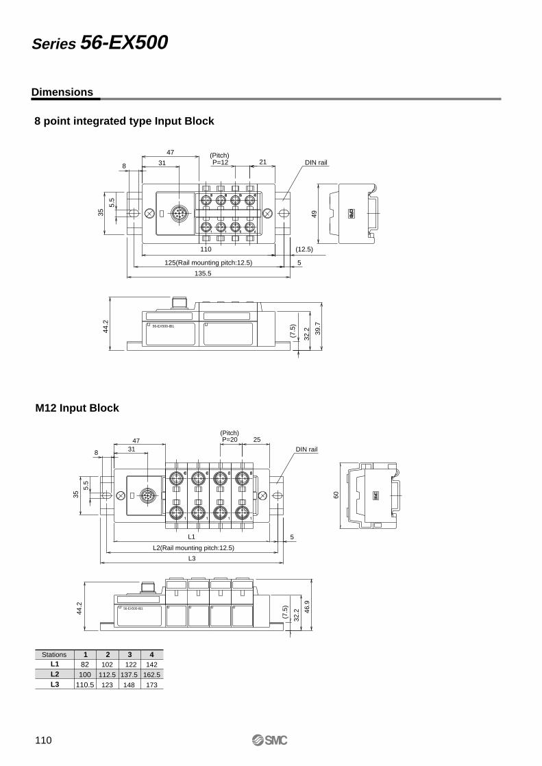
Series 56-EX500
Dimensions
8 point integrated type Input Block
(12.5)
(7.5
)
32.2 39
.7
44.2
4935
5.5
21P=12
47
31
5
8
110
125(Rail mounting pitch:12.5)
135.5
DIN rail(Pitch)
56-EX500-IB1
L3
L2(Rail mounting pitch:12.5)
L1
46.9
60
P=20 25
(7.5
)
32.244
.235
5.5
4731
5
8
M12 Input Block
(Pitch)
DIN rail
56-EX500-IB1
L1L2L3
Stations 2 3 4102
112.5
123
122
137.5
148
142
162.5
173
182100
110.5
110
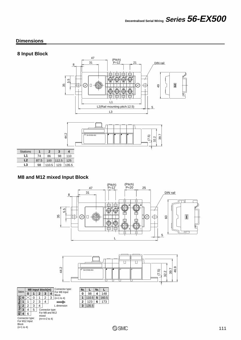
Series 56-EX500Decentralised Serial Wiring
Dimensions
8 Input Block
M8 and M12 mixed Input Block
L1L2L3
Stations 2 3 486
100
110.5
98
112.5
123
110
125
135.5
174
87.598
(7.5
)
32.2 39
.7
44.2
4935
5.5
21P=12
47
31
5
8
L1
L2(Rail mounting pitch:12.5)
L3
DIN rail(Pitch)
56-EX500-IB1
39.7
46.9
60
P=12 P=20 25
L
(7.5
)
32.244
.235
5.5
47
31
5
8
(Pitch) (Pitch)
DIN rail
56-EX500-IB1
L dimension173
160.5148
135.5123
110.598
LL No.
654
No.0
321(n=1 to 4)
BlockFor M8 InputConnector type:
(m+n=2 to 4)mixedFor M8 and M12Connector type:
(n=1 to 4)BlockFor M12 InputConnector type:
M12 I
nput
Blo
ck(n
)
M8 input block(m)Stations
543
4323210
6421
43210
43210
111

112
Safety Instructions
Note 1) ISO 4414: Pneumatic fluid power -- Recommendations for the application of equipment to transmission and control systems.
Note 2) JIS B 8370: Pneumatic system axion
Warning
Caution : Operator error could result in injury or equipment damage.
Warning : Operator error could result in serious injury or loss of life.
Danger : In extreme conditions, there is a possibility of serious injury or loss of life.
The following safety instructions are intended to prevent hazardous situations and/or equipment damage. The instructions indicate the level of potential hazard by labeling "Caution", "Warning", or "Danger". To ensure safety, please observe all safety practices, including ISO 4414 Note 1), JIS B8370 Note 2).
1. The compatibility of pneumatic equipment is the responsibility of the person who designs the pneumatic system or decides its specifications.Since the products specified here are used in various operating conditions, their compatibility with a specific pneumatic system must be based on specifications or post analysis and/or tests to meet a specific requirement.
2.Only trained personnel should operate pneumatically machinery and equipment.Compressed air can be dangerous if an operator is unfamiliar with it. Assembly, handling or repair of pneumatic systems should be performed by trained and experienced operators.
3. Do not service machinery/equipment or attempt to remove components until
the safety of the worker is confirmed.1. Inspection and maintenance of machinery/equipment should only be performed after confirming that
all safety locked-out control positions are engaged.2. When equipment is to be removed, confirm that all safety precautions have been followed. Cut the
pressure supply for the equipment and exhaust all residual compressed air in the system.3. Before restarting any machinery/equipment exercise caution to prevent quick extension of a cylinder
piston rod, etc. (Bleed air into the system gradually to create back pressure.)
4. Contact SMC if the product will be used in any of the following conditions.1. Conditions and environments beyond the given specifications or if product is used outdoors.2. Installation on equipment in conjunction with atomic energy, railway, air navigation, vehicles, medical
equipment, food and beverage, recreation equipment, emergency stop circuits, press applications or safety equipment.
3. An application which has the possibility of having a negative affect on people, property, or applications with special safety requirements.
113
Warning
Warning
Selection
Caution
Warning
Installation
Piping
Air Supply
Environment
Common PrecautionsBe sure to read before handing.
Warning
Maintenance
Warning
1. Do not install unless the safety instructions have been read and understood.Keep this catalogue on file for future reference.
2. MaintenanceWhen installing the product, allow for maintenance access.
3. Tightening torqueWhen installing the product, follow the torque specification.
1. Confirm specifications. Products represented in this catalogue are designed for use in
compressed air applications only (including vacuum), unless otherwise indicated. Do not use the products outside of their designed parameters. Contact SMC when using the product with fluids other than compressed air (including vacuum).
1. Before pipingBefore piping is connected, it should be thoroughly blown out with air (flushing) or washed to remove chips, cutting oil and other debris from inside the pipe.
2. Sealant tapeWhen installing piping or a fitting into a port, make sure that the sealant material does not clog the pressure port. Leave the first 1.5 to 2 thread turns exposed at the end of the pipe/ fitting when using sealant tape.
1. Operation fluidConsult with SMC when using the product in applications which use fluids other than compressed air (including vacuum). Regarding products for general fluids, consult with SMC regarding applicable fluids.
2. Large amount of drainage.Compressed air containing larger mount of drainage can cause malfunction of pneumatic equipment.Please installation of an air dryer and mist separator (Drain Catch) before air filter.
3. DrainIf condensation in the air filter is not emptied on a regular basis, condensation that flows to the outlet side can cause a malfunction. If it is difficult to check and remove, installation of a filter with an auto-drain function is recommended. Refer to Best Pneumatics for details on compressed air quality.
4. Use clean airDo not use compressed air which includes chemicals, synthetic oils containing organic solvents, salt, or corrosive gases, etc., as this can cause damage or malfunction.
1. Do not use in an environment where the product is directly exposed to corrosive gases, chemicals, sea water, water or steam.
2. In locations which receive direct sunlight, provide a protective cover, etc.
3. Do not operate in locations where vibration or impact occurs.
4. Do not use in locations where radiated heat will be received from nearby heat sources.
5. Avoid striking the product with a metallic object.
6. Avoid using this product in a non-explosive environment which can become explosive due to air leakage.
1. Maintenance procedures are outlined in the operation manual.Failure to follow proper procedures can result in product malfunction and or lead to damage to the equipment or machine.
2. MaintenanceIf handled improperly, compressed air can be dangerous. Assembly, handling and repair of pneumatic systems should only be performed by qualified personnel.
3. DrainRemove condensation from the filter bowl on a regular basis.
4. Shut down before maintenanceBefore attempting any kind of maintenance confirm that the supply pressure is shut off and all residual air pressure is released from the system to be worked on.
5. Start-up after maintenanceApply operating pressure and power to the equipment, then check for proper operation and possible air leaks. If operation is abnormal, verify product set-up parameters.
6. Do not make any modification to the product.
114
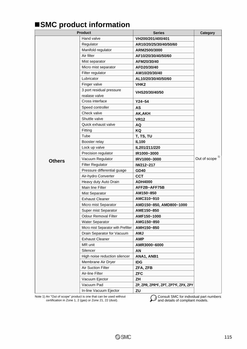
Note 1) An "Out of scope" product is one that can be used without certification in Zone 1, 2 (gas) or Zone 21, 22 (dust).
Hand valve
Regulator
Manifold regulator
Air filter
Mist separator
Micro mist separator
Filter regulator
Lubricator
Finger valve
3 port residual pressure
realase valveCross interface
Speed controller
Check valve
Shuttle valve
Quick exhaust valve
Fitting
Tube
Booster relay
Lock up valve
Precision regulator
Vacuum Regulator
Filter Regulator
Pressure differential guage
Air-hydro Converter
Heavy duty Auto Drain
Main line Filter
Mist Separator
Exhaust Cleaner
Micro mist Separator
Super mist Separator
Odour Removal Filter
Water Separator
Micro mist Separator with Prefilter
Drain Separator for Vacuum
Exhaust Cleaner
MR unit
Silencer
High noise reduction silencer
Membrane Air Dryer
Air Suction Filter
Air-line Filter
Vacuum Ejector
Vacuum Pad
In-line Vacuum Ejector
VH200/201/400/401
AR10/20/25/30/40/50/60
ARM2500/3000
AF10/20/30/40/50/60
AFM20/30/40
AFD20/30/40
AW10/20/30/40
AL10/20/30/40/50/60
VHK2
VHS20/30/40/50
Y24~54
AS
AK,AKH
VR12AQKQT, TS, TUIL100
IL201/211/220
IR1000~3000
IRV1000~3000
IW212~217GD40CCTADH4000AFF2B~AFF75BAM150~850AMC310~910
AMD150~850, AMD800~1000AME150~850
AMF150~1000AMG150~850
AMH150~850AMJ
AMP
AMR3000~6000
ANANA1, ANB1
IDGZFA, ZFB
ZFCZH
ZP, ZPR, ZPR*F, ZPT, ZPT*F, ZPX, ZPY
ZU
Series Category
Out of scope 1)
Others
Product
Consult SMC for individual part numbers and details of compliant models.
SMC product information
115

SMC CORPORATION 1-16-4 Shimbashi, Minato-ku, Tokio 105 JAPAN; Phone:03-3502-2740 Fax:03-3508-2480Specifications are subject to change without prior notice
and any obligation on the part of the manufacturer.
ARGENTINA, AUSTRALIA, BOLIVIA, BRASIL, CANADA, CHILE, CHINA, HONG KONG, INDIA, INDONESIA, MALAYSIA, MEXICO, NEW ZEALAND,PHILIPPINES, SINGAPORE, SOUTH KOREA, TAIWAN, THAILAND, USA, VENEZUELA
OTHER SUBSIDIARIES WORLDWIDE:
© DiskArt™ 1988
© DiskArt™ UKSMC Pneumatics (UK) LtdVincent Avenue, Crownhill,Milton Keynes, MK8 0ANPhone: +44 (0)800 1382930 Fax: +44 (0)1908-555064E-mail: [email protected]://www.smcpneumatics.co.uk
AustriaSMC Pneumatik GmbH (Austria).Girakstrasse 8, A-2100 KorneuburgPhone: +43 2262-62280, Fax: +43 2262-62285E-mail: [email protected]://www.smc.at
Czech RepublicSMC Industrial Automation CZ s.r.o.Hudcova 78a, CZ-61200 BrnoPhone: +420 5 414 24611, Fax: +420 5 412 18034E-mail: [email protected]://www.smc.cz
PortugalSMC Sucursal Portugal, S.A.Rua de Engº Ferreira Dias 452, 4100-246 PortoPhone: +351 22-610-89-22, Fax: +351 22-610-89-36E-mail: [email protected]://www.smces.es
BelgiumSMC Pneumatics N.V./S.A.Nijverheidsstraat 20, B-2160 WommelgemPhone: +32 (0)3-355-1464, Fax: +32 (0)3-355-1466E-mail: [email protected]://www.smcpneumatics.be
LithuaniaUAB Ottensten LietuvaSavanoriu pr. 180, LT-2600 Vilnius, LithuaniaPhone/Fax: +370-2651602
LatviaSMC Pneumatics Latvia SIASmerla 1-705, Riga LV-1006, LatviaPhone: +371 (0)777-94-74, Fax: +371 (0)777-94-75E-mail: [email protected]://www.smclv.lv
SwedenSMC Pneumatics Sweden ABEkhagsvägen 29-31, S-141 71 HuddingePhone: +46 (0)8-603 12 00, Fax: +46 (0)8-603 12 90E-mail: [email protected]://www.smc.nu
FranceSMC Pneumatique, S.A.1, Boulevard de Strasbourg, Parc Gustave EiffelBussy Saint Georges F-77607 Marne La Vallee Cedex 3Phone: +33 (0)1-6476 1000, Fax: +33 (0)1-6476 1010E-mail: [email protected]://www.smc-france.fr
FinlandSMC Pneumatics Finland OYPL72, Tiistinniityntie 4, SF-02031 ESPOOPhone: +358 (0)9-859 580, Fax: +358 (0)9-8595 8595E-mail: [email protected]://www.smc.fi
EstoniaSMC Pneumatics Estonia OÜLaki 12-101, 106 21 TallinnPhone: +372 (0)6 593540, Fax: +372 (0)6 593541E-mail: [email protected]://www.smcpneumatics.ee
GreeceS. Parianopoulus S.A.7, Konstantinoupoleos Street, GR-11855 AthensPhone: +30 (0)1-3426076, Fax: +30 (0)1-3455578E-mail: [email protected]://www.smceu.com
TurkeyEntek Pnömatik San. ve Tic Ltd. Sti.Perpa Tic. Merkezi Kat: 11 No: 1625, TR-80270 Okmeydani IstanbulPhone: +90 (0)212-221-1512, Fax: +90 (0)212-221-1519E-mail: [email protected]://www.entek.com.tr
PolandSMC Industrial Automation Polska Sp.z.o.o.ul. Konstruktorska 11A, PL-02-673 Warszawa, Phone: +48 22 548 5085, Fax: +48 22 548 5087E-mail: [email protected]://www.smc.pl
NetherlandsSMC Pneumatics BVDe Ruyterkade 120, NL-1011 AB AmsterdamPhone: +31 (0)20-5318888, Fax: +31 (0)20-5318880E-mail: [email protected]://www.smcpneumatics.nl
IrelandSMC Pneumatics (Ireland) Ltd.2002 Citywest Business Campus, Naas Road, Saggart, Co. DublinPhone: +353 (0)1-403 9000, Fax: +353 (0)1-464-0500E-mail: [email protected]://www.smcpneumatics.ie
HungarySMC Hungary Ipari Automatizálási Kft.Budafoki ut 107-113, H-1117 BudapestPhone: +36 1 371 1343, Fax: +36 1 371 1344E-mail: [email protected]://www.smc-automation.hu
SwitzerlandSMC Pneumatik AGDorfstrasse 7, CH-8484 WeisslingenPhone: +41 (0)52-396-3131, Fax: +41 (0)52-396-3191E-mail: [email protected]://www.smc.ch
ItalySMC Italia S.p.AVia Garibaldi 62, I-20061Carugate, (Milano)Phone: +39 (0)2-92711, Fax: +39 (0)2-9271365E-mail: [email protected]://www.smcitalia.it
GermanySMC Pneumatik GmbHBoschring 13-15, D-63329 EgelsbachPhone: +49 (0)6103-4020, Fax: +49 (0)6103-402139E-mail: [email protected]://www.smc-pneumatik.de
SloveniaSMC industrijska Avtomatika d.o.o.Grajski trg 15, SLO-8360 ZuzemberkPhone: +386 738 85240 Fax: +386 738 85249E-mail: [email protected]://www.smc-ind-avtom.si
SlovakiaSMC Priemyselná Automatizáciá, s.r.o.Námestie Martina Benku 10SK-81107 BratislavaPhone: +421 2 444 56725, Fax: +421 2 444 56028E-mail: [email protected]://www.smc.sk
RomaniaSMC Romania srlStr Frunzei 29, Sector 2, BucharestPhone: +40 213205111, Fax: +40 213261489E-mail: [email protected]://www.smcromania.ro
NorwaySMC Pneumatics Norway A/SVollsveien 13 C, Granfos Næringspark N-1366 LysakerTel: +47 67 12 90 20, Fax: +47 67 12 90 21E-mail: [email protected]://www.smc-norge.no
DenmarkSMC Pneumatik A/SKnudsminde 4B, DK-8300 OdderPhone: +45 70252900, Fax: +45 70252901E-mail: [email protected]://www.smcdk.com
RussiaSMC Pneumatik LLC.36/40 Sredny pr. St. Petersburg 199004Phone.:+812 118 5445, Fax:+812 118 5449E-mail: [email protected]://www.smc-pneumatik.ru
SpainSMC España, S.A.Zuazobidea 14, 01015 VitoriaPhone: +34 945-184 100, Fax: +34 945-184 124E-mail: [email protected]://www.smces.es
http://www.smceu.comhttp://www.smcworld.com
EUROPEAN SUBSIDIARIES:
Produced and printed by SMC European Marketing Centre 12/04
BulgariaSMC Industrial Automation Bulgaria EOOD16 kliment Ohridski Blvd., fl.13 BG-1517 SofiaPhone:+359 2 9744492, Fax:+359 2 9744519E-mail: [email protected]://www.smc.bg