Embed Size (px)
Citation preview
University of Florida | Herbert Wertheim College of Engineering | Honors Thesis | Spring 2020 1
Abstract— This study aims to design, build, and test a robotic
system to produce four 10-inch pizzas in under 5 minutes. To
support subsystems that apply tomato sauce and shred cheese, a
rotating cantilever beam robotic system was designed. Motor
specifications were calculated before implementation. Subsystems
and their actuators showed desirable performance during
actuation. As well, stiffness and improved tolerances would benefit
the entire system for future system-level integration.
Index Terms— Design, Pizza, Robot, Tolerances, Torque
I. INTRODUCTION
HE topic of this study includes creating the proof of
concept of a robotic system that prepares food. The purpose
of this technology is to alleviate the fast-casual restaurant
industry’s 150 percent turnover rate [1]. With over 300,000
quick service and fast casual restaurants in the US, this
volatility becomes a problem at scale [2]. Implementation of
robotic systems may exclude workers from tedious tasks,
kitchen hazards, and proactively reduce food-borne illness
transmissions. Used as a tool, this technology can reduce the
demanding nature of the job, easing turnover.
Some examples of technology currently in-use, includes
McDonalds’ ordering kiosks and Caliburger’s installment of
Flippy, a robotic arm that flips burgers and works a fryer [3-4].
An area that this technology may automate includes pizza. Not
only a very popular food, pizza has layers and offers simple
preparation processes.
This study aims to explore the mechanical and electrical
engineering design of a robot that prepares four 10-inch pizzas
in under 5 minutes. Tested features of the system will be cheese
shredding, sauce pumping, and pepperoni slicing. Once the
designed machine has ingredients manually loaded and set to
run, the processing should be entirely hands-off to exhibit
autonomy and practicality over pre-existing appliances.
II. METHODOLOGY
Designs and approaches were selected based on simplicity,
economy, and food safety. The system design was pipelined
into different categories to develop the product. Subsystems
were programmed and tested individually before final system
integration. Design reviews were held as needed to ensure
milestones were reached with punctuality and efficacy.
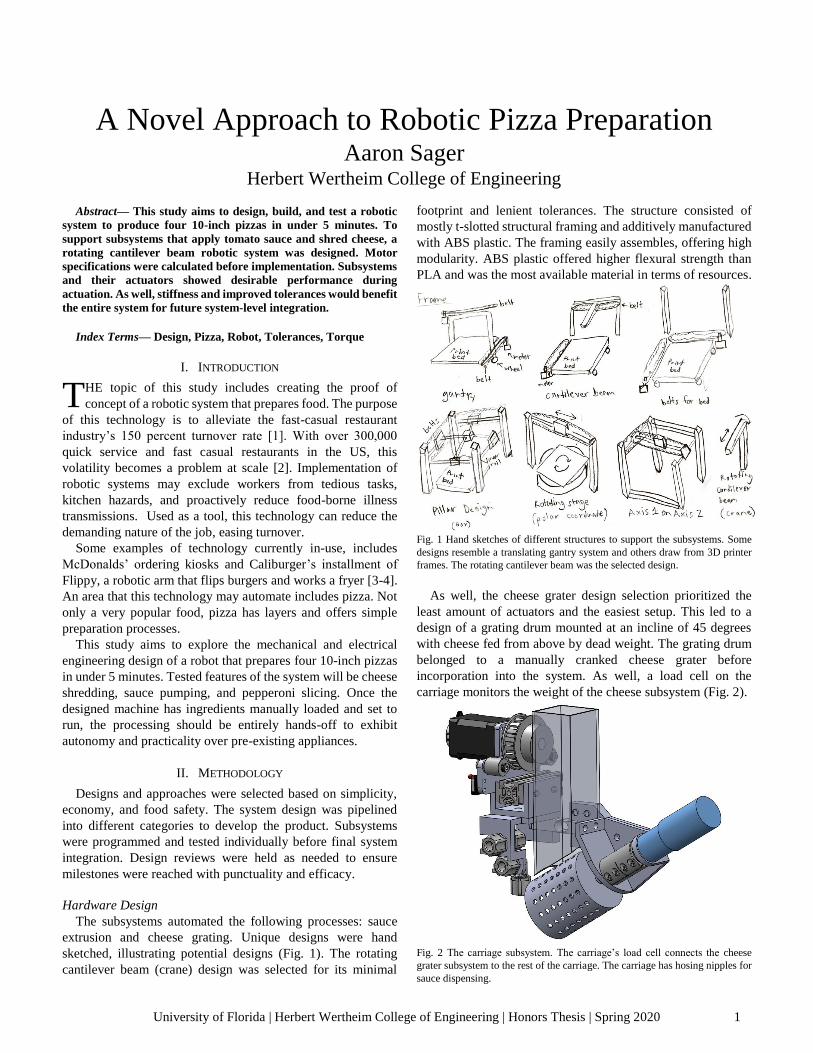
Hardware Design
The subsystems automated the following processes: sauce
extrusion and cheese grating. Unique designs were hand
sketched, illustrating potential designs (Fig. 1). The rotating
cantilever beam (crane) design was selected for its minimal
footprint and lenient tolerances. The structure consisted of
mostly t-slotted structural framing and additively manufactured
with ABS plastic. The framing easily assembles, offering high
modularity. ABS plastic offered higher flexural strength than
PLA and was the most available material in terms of resources.
Fig. 1 Hand sketches of different structures to support the subsystems. Some
designs resemble a translating gantry system and others draw from 3D printer
frames. The rotating cantilever beam was the selected design.
As well, the cheese grater design selection prioritized the
least amount of actuators and the easiest setup. This led to a
design of a grating drum mounted at an incline of 45 degrees
with cheese fed from above by dead weight. The grating drum
belonged to a manually cranked cheese grater before
incorporation into the system. As well, a load cell on the
carriage monitors the weight of the cheese subsystem (Fig. 2).
Fig. 2 The carriage subsystem. The carriage’s load cell connects the cheese
grater subsystem to the rest of the carriage. The carriage has hosing nipples for
sauce dispensing.
A Novel Approach to Robotic Pizza Preparation Aaron Sager
Herbert Wertheim College of Engineering
T
University of Florida | Herbert Wertheim College of Engineering | Honors Thesis | Spring 2020 2
Using the density of mozzarella cheese and the
recommended serving by weight on a given pizza diameter, the
volume of the cheese container was calculated to accommodate
at least four pizzas [5-6]. Dividing the volume V by the length l
of the container, the cross-sectional area for a box tube was
found and searched on McMaster-Carr for part sourcing (1).
𝐶𝑟𝑜𝑠𝑠 − 𝑆𝑒𝑐𝑡𝑖𝑜𝑛𝑎𝑙 𝐴𝑟𝑒𝑎 = 𝑉/𝑙 (1)
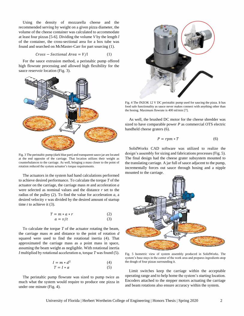
For the sauce extrusion method, a peristaltic pump offered
high flowrate processing and allowed high flexibility for the
sauce reservoir location (Fig. 3).
Fig. 3 The peristaltic pump (dark blue part) and transparent sauce jar are located
at the end opposite of the carriage. That location utilizes their weight as
counterbalances to the carriage. As well, bringing a mass closer to the point of
rotation reduced the system actuator’s torque requirements.
The actuators in the system had hand calculations performed
to achieve desired performance. To calculate the torque T of the
actuator on the carriage, the carriage mass m and acceleration a
were selected as nominal values and the distance r set to the
radius of the pulley (2). To find the value for acceleration a, a
desired velocity v was divided by the desired amount of startup
time t to achieve it (3).
𝑇 = 𝑚 ∗ 𝑎 ∗ 𝑟 (2)
𝑎 = 𝑣/𝑡 (3)
To calculate the torque T of the actuator rotating the beam,
the carriage mass m and distance to the point of rotation d
squared were used to find the rotational inertia (4). That
approximated the carriage mass as a point mass in space,
assuming the beam weight as negligible. With rotational inertia
I multiplied by rotational acceleration α, torque T was found (5).
𝐼 = 𝑚 ∗ 𝑑2 (4)
𝑇 = 𝐼 ∗ 𝛼 (5)
The peristaltic pump flowrate was sized to pump twice as
much what the system would require to produce one pizza in
under one minute (Fig. 4).
Fig. 4 The INZOK 12 V DC peristaltic pump used for saucing the pizza. It has
food safe functionality as sauce never makes connect with anything other than
the hosing. Maximum flowrate is 400 ml/min [7].
As well, the brushed DC motor for the cheese shredder was
sized to have comparable power P as commercial OTS electric
handheld cheese graters (6).
𝑃 = 𝑟𝑝𝑚 ∗ 𝑇 (6)
SolidWorks CAD software was utilized to realize the
design’s assembly for sizing and fabrications processes (Fig. 5).
The final design had the cheese grater subsystem mounted to
the translating carriage. A jar full of sauce adjacent to the pump,
incrementally forces out sauce through hosing and a nipple
mounted to the carriage.
Fig. 5 Isometric view of system assembly produced in SolidWorks. The
system’s base stays in the center of the work area and prepares ingredients atop
the dough of four pizzas surrounding it.
Limit switches keep the carriage within the acceptable
operating range and to help home the system’s starting location.
Encoders attached to the stepper motors actuating the carriage
and beam rotations also ensure accuracy within the system.
University of Florida | Herbert Wertheim College of Engineering | Honors Thesis | Spring 2020 3
Electrical Design
For control of the DC motor and peristaltic pump, an H-
bridge actuated each motor independently at different speeds
based on separate enable and pulse-width modulation (PWM)
signals. The H-bridge and stepper motor drivers operated with
a 12 volt (V) and a 24 V power supply, respectively.
To control the entire system, an Arduino MEGA 2560 R3
offered an ample 54 digital input/output (IO) pins with 15
capable of providing PWM. Additional electronics include an
OLED display to indicate to the user the current function or
process of the robotic system.
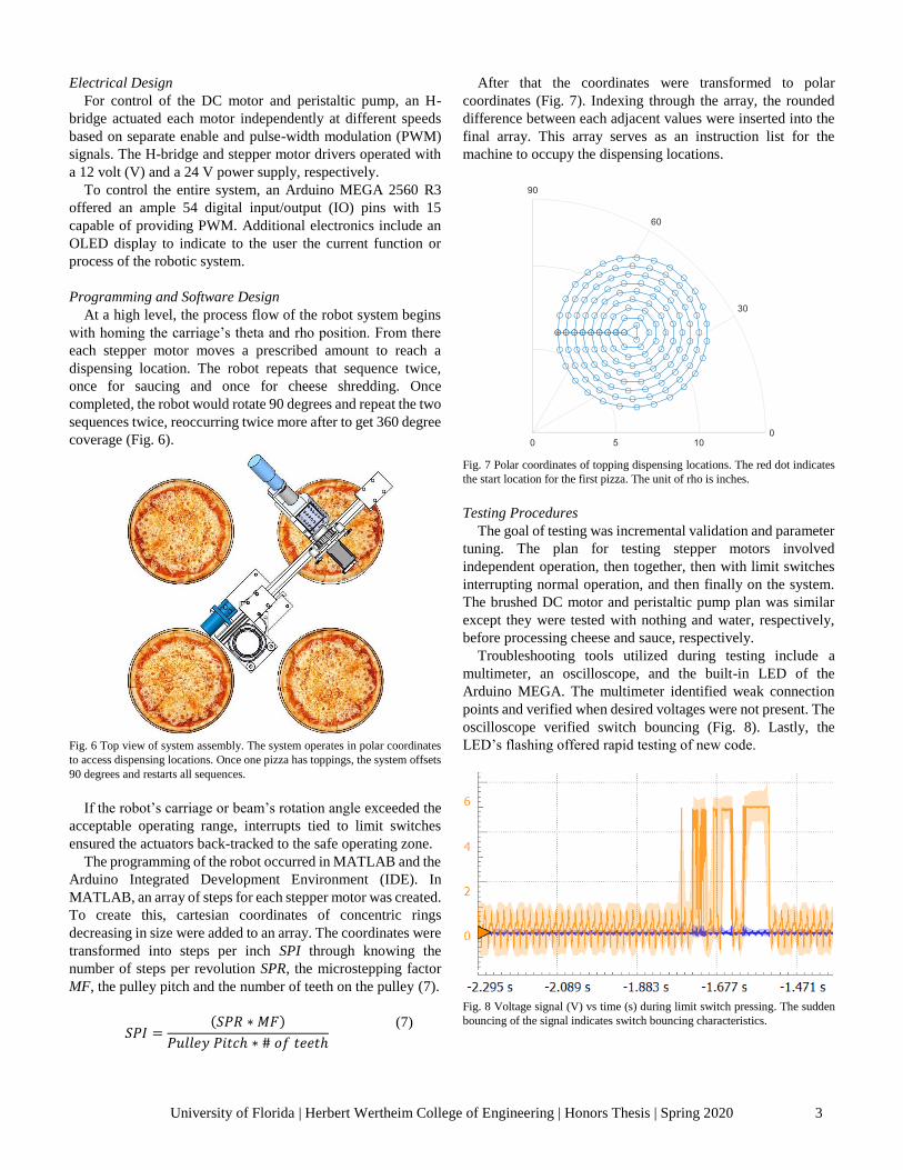
Programming and Software Design
At a high level, the process flow of the robot system begins
with homing the carriage’s theta and rho position. From there
each stepper motor moves a prescribed amount to reach a
dispensing location. The robot repeats that sequence twice,
once for saucing and once for cheese shredding. Once
completed, the robot would rotate 90 degrees and repeat the two
sequences twice, reoccurring twice more after to get 360 degree
coverage (Fig. 6).
Fig. 6 Top view of system assembly. The system operates in polar coordinates
to access dispensing locations. Once one pizza has toppings, the system offsets
90 degrees and restarts all sequences.
If the robot’s carriage or beam’s rotation angle exceeded the
acceptable operating range, interrupts tied to limit switches
ensured the actuators back-tracked to the safe operating zone.
The programming of the robot occurred in MATLAB and the
Arduino Integrated Development Environment (IDE). In
MATLAB, an array of steps for each stepper motor was created.
To create this, cartesian coordinates of concentric rings
decreasing in size were added to an array. The coordinates were
transformed into steps per inch SPI through knowing the
number of steps per revolution SPR, the microstepping factor
MF, the pulley pitch and the number of teeth on the pulley (7).
𝑆𝑃𝐼 =(𝑆𝑃𝑅 ∗ 𝑀𝐹)
𝑃𝑢𝑙𝑙𝑒𝑦 𝑃𝑖𝑡𝑐ℎ ∗ # 𝑜𝑓 𝑡𝑒𝑒𝑡ℎ
(7)
After that the coordinates were transformed to polar
coordinates (Fig. 7). Indexing through the array, the rounded
difference between each adjacent values were inserted into the
final array. This array serves as an instruction list for the
machine to occupy the dispensing locations.
Fig. 7 Polar coordinates of topping dispensing locations. The red dot indicates
the start location for the first pizza. The unit of rho is inches.
Testing Procedures
The goal of testing was incremental validation and parameter
tuning. The plan for testing stepper motors involved
independent operation, then together, then with limit switches
interrupting normal operation, and then finally on the system.
The brushed DC motor and peristaltic pump plan was similar
except they were tested with nothing and water, respectively,
before processing cheese and sauce, respectively.
Troubleshooting tools utilized during testing include a
multimeter, an oscilloscope, and the built-in LED of the
Arduino MEGA. The multimeter identified weak connection
points and verified when desired voltages were not present. The
oscilloscope verified switch bouncing (Fig. 8). Lastly, the
LED’s flashing offered rapid testing of new code.
Fig. 8 Voltage signal (V) vs time (s) during limit switch pressing. The sudden
bouncing of the signal indicates switch bouncing characteristics.
University of Florida | Herbert Wertheim College of Engineering | Honors Thesis | Spring 2020 4
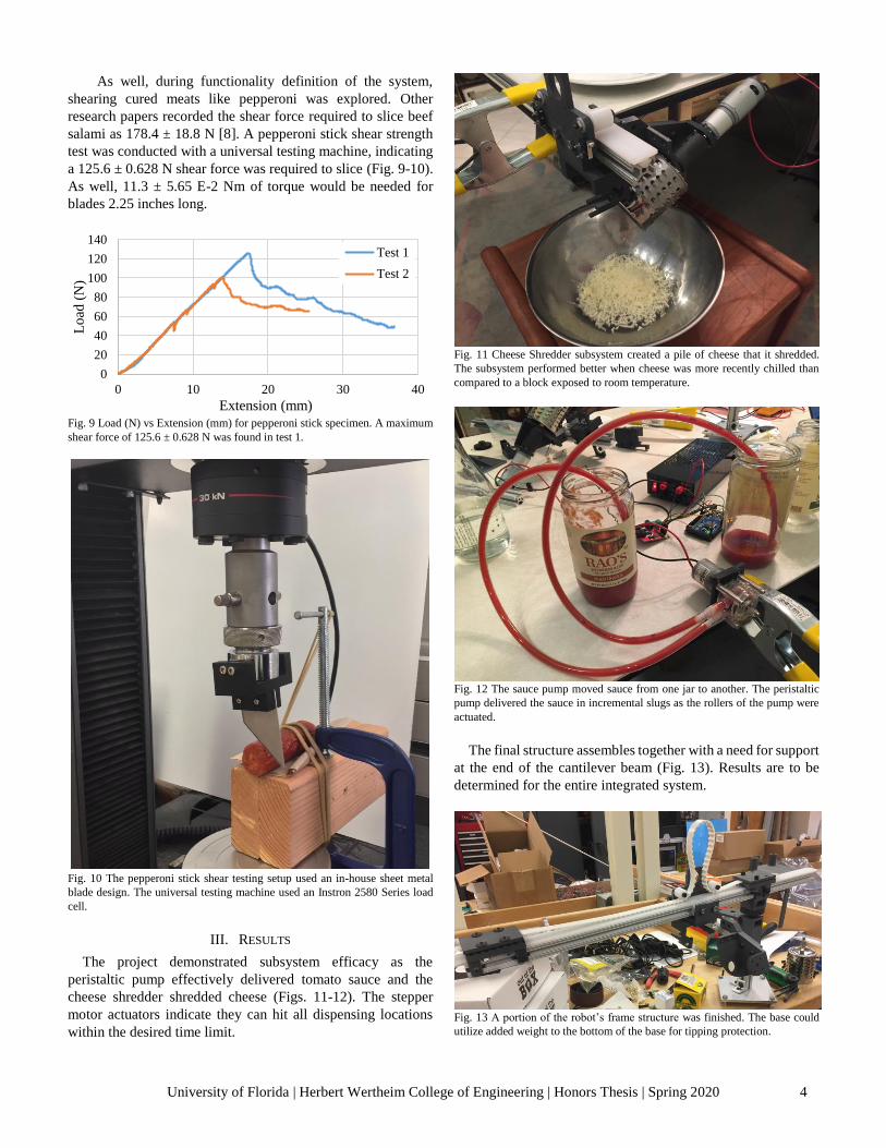
As well, during functionality definition of the system,
shearing cured meats like pepperoni was explored. Other
research papers recorded the shear force required to slice beef
salami as 178.4 ± 18.8 N [8]. A pepperoni stick shear strength
test was conducted with a universal testing machine, indicating
a 125.6 ± 0.628 N shear force was required to slice (Fig. 9-10).
As well, 11.3 ± 5.65 E-2 Nm of torque would be needed for
blades 2.25 inches long.
Fig. 9 Load (N) vs Extension (mm) for pepperoni stick specimen. A maximum
shear force of 125.6 ± 0.628 N was found in test 1.
Fig. 10 The pepperoni stick shear testing setup used an in-house sheet metal
blade design. The universal testing machine used an Instron 2580 Series load
cell.
III. RESULTS
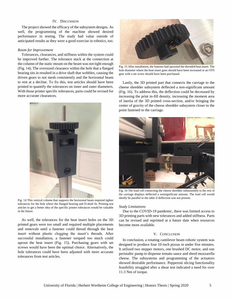
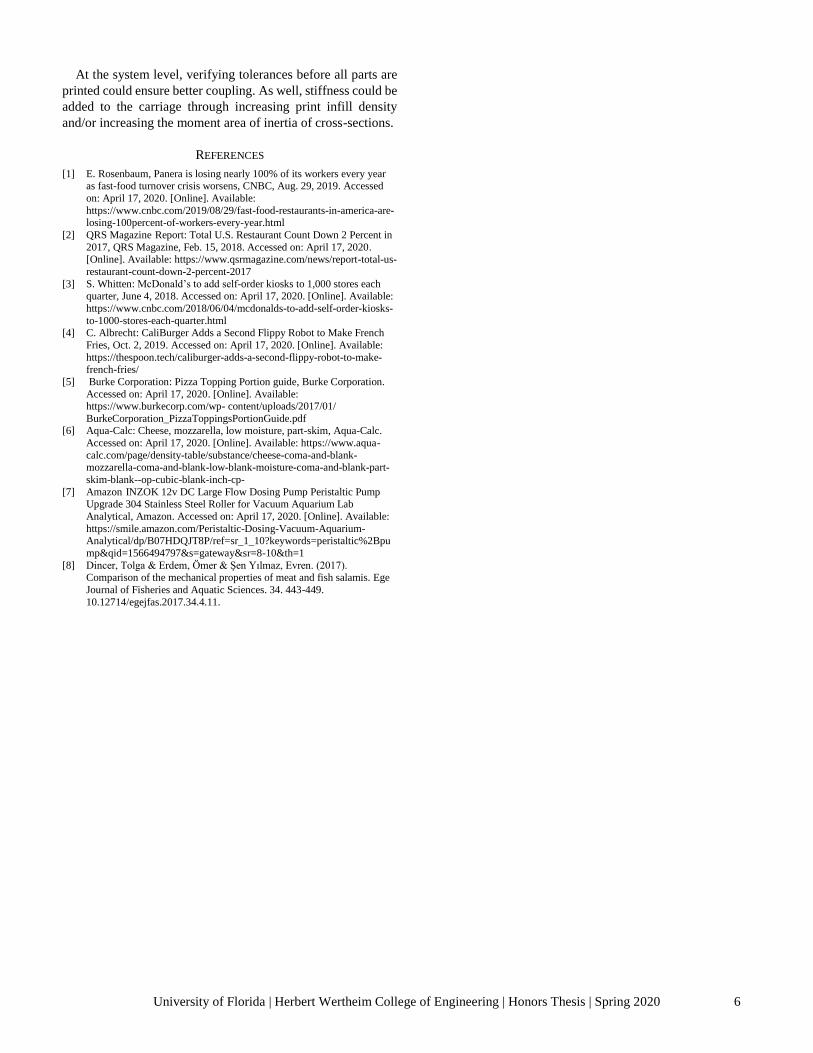
The project demonstrated subsystem efficacy as the
peristaltic pump effectively delivered tomato sauce and the
cheese shredder shredded cheese (Figs. 11-12). The stepper
motor actuators indicate they can hit all dispensing locations
within the desired time limit.
Fig. 11 Cheese Shredder subsystem created a pile of cheese that it shredded.
The subsystem performed better when cheese was more recently chilled than
compared to a block exposed to room temperature.
Fig. 12 The sauce pump moved sauce from one jar to another. The peristaltic
pump delivered the sauce in incremental slugs as the rollers of the pump were
actuated.
The final structure assembles together with a need for support
at the end of the cantilever beam (Fig. 13). Results are to be
determined for the entire integrated system.
Fig. 13 A portion of the robot’s frame structure was finished. The base could
utilize added weight to the bottom of the base for tipping protection.
0
20
40
60
80
100
120
140
0 10 20 30 40
Lo
ad (
N)
Extension (mm)
Test 1
Test 2
University of Florida | Herbert Wertheim College of Engineering | Honors Thesis | Spring 2020 5
IV. DISCUSSION
The project showed the efficacy of the subsystem designs. As
well, the programming of the machine showed desired
performance in testing. The study had value outside of
anticipated results as they were a good exercise in robotics, too.
Room for Improvement
Tolerances, clearances, and stiffness within the system could
be improved further. The tolerance stack at the connection at
the column of the static mount on the beam was not tight enough
(Fig. 14). The oversized clearance within the hole that a flanged
bearing sits in resulted in a drive shaft that wobbles, causing the
driven gears to not mesh consistently and the horizontal beam
to rest at a decline. To fix this, test articles should have been
printed to quantify the tolerances on inner and outer diameters.
With those printer specific tolerances, parts could be revised for
more accurate clearances.
Fig. 14 This vertical column that supports the horizontal beam required tighter
tolerances for the hole where the flanged bearing and D-shaft fit. Printing test
articles to get a better idea of the specific printer tolerances would be valuable
in the future.
As well, the tolerances for the heat insert holes on the 3D
printed gears were too small and required multiple placements
and removals until a fastener could thread through the heat
insert without plastic clogging the insert’s threads. After
successful installation, a fastener torqued too much could
uproot the heat insert (Fig. 15). Purchasing gears with set
screws would have been the optimal choice. Alternatively, the
hole tolerances could have been adjusted with more accurate
tolerances from test articles.
Fig. 15 After installation, the fastener had uprooted the threaded heat insert. The
hole diameter where the heat insert goes should have been increased or an OTS
gear with a set screw should have been purchased.
Lastly, the 3D printed part that connects the carriage to the
cheese shredder subsystem deflected a non-significant amount
(Fig. 16). To address this, the deflection could be decreased by
increasing the print in-fill density, increasing the moment area
of inertia of the 3D printed cross-section, and/or bringing the
center of gravity of the cheese shredder subsystem closer to the
point fastened to the carriage.
Fig. 16 The load cell connecting the cheese shredder subassembly to the rest of
the carriage displays deflected a nonsignificant amount. The load cell would
ideally be parallel to the table if deflection was not present.
Study Limitations
Due to the COVID-19 pandemic, there was limited access to
3D printing parts with new tolerances and added stiffness. Parts
can be revised and reprinted at a future date when resources
become more available.
V. CONCLUSION
In conclusion, a rotating cantilever beam robotic system was
designed to produce four 10-inch pizzas in under five minutes.
It utilized two stepper motors, one brushed DC motor, and one
peristaltic pump to dispense tomato sauce and shred mozzarella
cheese. The subsystems and programming of the actuators
showed desirable performance. Pepperoni slicing functionality
feasibility struggled after a shear test indicated a need for over
11.3 Nm of torque.
University of Florida | Herbert Wertheim College of Engineering | Honors Thesis | Spring 2020 6
At the system level, verifying tolerances before all parts are
printed could ensure better coupling. As well, stiffness could be
added to the carriage through increasing print infill density
and/or increasing the moment area of inertia of cross-sections.
REFERENCES
[1] E. Rosenbaum, Panera is losing nearly 100% of its workers every year as fast-food turnover crisis worsens, CNBC, Aug. 29, 2019. Accessed
on: April 17, 2020. [Online]. Available:
https://www.cnbc.com/2019/08/29/fast-food-restaurants-in-america-are-losing-100percent-of-workers-every-year.html
[2] QRS Magazine Report: Total U.S. Restaurant Count Down 2 Percent in
2017, QRS Magazine, Feb. 15, 2018. Accessed on: April 17, 2020. [Online]. Available: https://www.qsrmagazine.com/news/report-total-us-
restaurant-count-down-2-percent-2017
[3] S. Whitten: McDonald’s to add self-order kiosks to 1,000 stores each
quarter, June 4, 2018. Accessed on: April 17, 2020. [Online]. Available:
https://www.cnbc.com/2018/06/04/mcdonalds-to-add-self-order-kiosks-
to-1000-stores-each-quarter.html [4] C. Albrecht: CaliBurger Adds a Second Flippy Robot to Make French
Fries, Oct. 2, 2019. Accessed on: April 17, 2020. [Online]. Available:
https://thespoon.tech/caliburger-adds-a-second-flippy-robot-to-make-french-fries/
[5] Burke Corporation: Pizza Topping Portion guide, Burke Corporation.
Accessed on: April 17, 2020. [Online]. Available: https://www.burkecorp.com/wp- content/uploads/2017/01/
BurkeCorporation_PizzaToppingsPortionGuide.pdf [6] Aqua-Calc: Cheese, mozzarella, low moisture, part-skim, Aqua-Calc.
Accessed on: April 17, 2020. [Online]. Available: https://www.aqua-
calc.com/page/density-table/substance/cheese-coma-and-blank-mozzarella-coma-and-blank-low-blank-moisture-coma-and-blank-part-
skim-blank--op-cubic-blank-inch-cp-
[7] Amazon INZOK 12v DC Large Flow Dosing Pump Peristaltic Pump Upgrade 304 Stainless Steel Roller for Vacuum Aquarium Lab
Analytical, Amazon. Accessed on: April 17, 2020. [Online]. Available:
https://smile.amazon.com/Peristaltic-Dosing-Vacuum-Aquarium-Analytical/dp/B07HDQJT8P/ref=sr_1_10?keywords=peristaltic%2Bpu
mp&qid=1566494797&s=gateway&sr=8-10&th=1
[8] Dincer, Tolga & Erdem, Ömer & Şen Yılmaz, Evren. (2017). Comparison of the mechanical properties of meat and fish salamis. Ege
Journal of Fisheries and Aquatic Sciences. 34. 443-449.
10.12714/egejfas.2017.34.4.11.