Embed Size (px)
Citation preview
A New Method for Indoor Location Base on Radio Frequency
Identification
Rung-Ching Chen, Sheng-Ling Huang
Department of information management
Chaoyang University of Technology
168, Jifong East Road, Wufong Township, Taichung County 41349
Taiwn, R.O.C
[email protected] http://www.cyut.edu.tw/~crching
Abstract: - In recent years, there has dramatic proliferation of research concerned with Radio Frequency
Identification (RFID). The RFID technologies are getting considerable attentions not only academic research but
also the applications of enterprise. One of most important issues of applications is the indoor position location.
Many researchers have used varied technologies to perform the tracking of indoor position location. In this paper,
we will purpose a new method using RFID tags to perform indoor position location tracking, too. This method
uses Received Signal Strength (RSS) to collect signal strength from reference tags beforehand. Next, signal
strength is used to set up Power Level areas of ranges by reference tags. And then, using signal strength from
reference tags to match signal strength by track tags. Finally, when track tags is set up into indoor environments,
it will find out the position of neighboring reference tags, and using arithmetic mean to calculate the location
values. A preliminary experiment proves that our method provides a better precision than LANDMRC system.
Key-Words: -RFID, indoor position location, RSS, Powel Level, location identification, LANDMRC
1 Introduction In recent years, the position location system with
ubiquitous computing has become great importance
and the use of technology in the position location
system has increasingly the object of study and
enterprise applications. Pertinent to the applications
of position location system: such as in the hospital,
the location system can be used to track iatrical
apparatus and check tabs on patient; personnel
management of the office block; merchandise
management in market and the process management
of the manufacturing industry etc. The position
location system can enhance the manager to manage
efficiently and expediently [2][8][12][20][22].
One of the rapidly advancing technologies of
position location system research is Global
positioning system (GPS), but GPS has to keep Light
of Sight (LoS) with satellite otherwise GPS can’t
perform position of track object. And then in the
indoor environment, the receiver should not receive
Signal because Signal subject to buildings impact.
This congenital limit make GPS can’t be used for
indoor position location system. A growing number
of research studies are now available to perform
indoor position include Infrared, Ultrasonic Bats,
IEEE 802.11, sensor and Radio Frequency
Identification (RFID)[3][7].
Indoor position location systems have been
ceaseless innovating and developing. Researchers
have indicated that these location systems have some
disadvantages. For examples, infrared has weak in
penetrability and it transmits distance too short;
Ultrasonic Bats can get better location accuracy but
the apparatus is too expensive; although IEEE 802.11
is easy to construction, it can’t provide better
accuracy. By contrast, RFID is convenience to use
and the RFID apparatus is inexpensive, so RFID is a
better scheme to applying to indoor position than
other technology [9][13][18].
In this paper, we will purpose position schemes
placed four RFID readers in environment corners and
placed several RFID tags in environment beforehand,
and then use Received Signal Strength (RSS) to
collect signal strength from reference tags. Set up
Power Level area of the range with the signal strength
from the relative distance of reference tags and
readers. Next, we collect these signal data to construct
relative environmental models. While the track tag is
entered indoor environment, first, we get information
that track tags in which area range by Power Level
concept. Then, we use signal strength from reference
tag to match signal strength from track tag to find out
neighboring reference tags position, and then using
arithmetic mean to make a calculation of these
WSEAS TRANSACTIONS on COMMUNICATIONS Rung-Ching Chen, Sheng-Ling Huang
ISSN: 1109-2742 618 Issue 7, Volume 8, July 2009
position location values, by this method to figure
down track tags position location.
The rest of the paper is organized as follows. In
section 2 we discuss about background knowledge of
relevant research. In section 3 we discuss the mixture
indoor position location system. In section 4, system
simulations and experiment results are given. Finally,
we make conclusions and future works in section 5.
2 Related Work In this section, we will discuss the background
knowledge of constructing our indoor position
location system by RFID methods. We would further
introduction include: A Review of Relevant Position
Technology, Location identification based on
dynamic active RFID calibration (LANDMRC),
Received Signal Strength (RSS), and Power Level.
2.1 A Review of Relevant Position Technology The relevant position technology used in recent
year are (1) Infrared, (2) Ultrasonic, (3) IEEE 802.11,
(4) Sensor and (5) Radio Frequency Identification
(RFID). We described as follows.
2.1.1 Infrared
In 1992, infrared technology was applied to indoor
position location system. In AT&T laboratory,
“Active Badge” position location system was
purposed by R. Want, et al [19]. This system
provides indoor position location service by infrared
technology. It uses a badge worm by a person, and the
badge will emit signal of infrared every 10 seconds.
Infrared sensor will be placed in indoor environment
and relay infrared signal form badge. The position
location system can estimate location information of
badge. However infrared technology still has
disadvantages when it is used to indoor position
location. Infrared has to keep Light of Sight (LoS), so
it has weak in penetrability and its transition distance
is too short. Due to these disadvantages, infrared
technology does not suit to indoor position.
2.1.2 Ultrasonic “Cricket Location” position location system and
“Active Bat” position location system are typical
system of Ultrasonic technology [15][21]. They used
“Time-of-flight” technology to measure location
information of a track object.
These Ultrasonic systems have better location
accuracy when they are used in indoor position, but
their apparatus are too expensive. Therefore,
Ultrasonic technology can’t get low-cost when the
system will be practically built.
2.1.3 IEEE 802.11
In 2000, “RADAR” position location system was
purposed by research department of Microsoft. It uses
wireless sensor network to track object. In this
system, it uses equipment of network which
equipment conform IEEE 802.11. “RADAR”
position location system used many AP (Access
Points) to lay over area of position environment. In
the systematic procedure, the procedure has two parts,
first part is the off-line phase and second part is the
real-time phase. In the off-line phase, the system will
record information about the radio signal as a
function of the user’s location. And then they collect
these signal information to construct model of
environment. In the real-time phase, the system will
match signal strength of user’s with signal strength of
remote database to calculate user’s location [1].
The disadvantages of “RADAR” position location
system are (a) the track object has to worn related
department; (b) the communication technology is apt
to receive the interference of other communication
apparatuses; (c) the system mean error about 3~4
meter, therefore the system accuracy doesn’t accord
with expecting.
2.1.4 Sensor
In 2000, “Smart Floor” position location system
was purposed by R. J. Orr, et al. [14]. It used pressure
sensors to achieve position location. In this method,
they put pressure sensors under the floor. When
person or object goes through the floor, sensor will
receive the change of pressure. By this way, the
system can get location information. The accuracy of
“Smart Floor” system is conform request, but the cost
of construction has to considerable when sensor put a
large number.
2.1.5 Radio Frequency Identification (RFID)
In recent years, a lot of research used RFID
technology to do indoor position location. “SpotON”
position location system is one of examples of RFID
applications for indoor position location which was
proposed by J. Hightower et al[5][6]. “SpotON”
position location system used Aggregation algorithm
to estimate signal strength. In their system, the
position estimation of track tag used other
homogeneity sensors and estimate of dispersing type
to perform position location.
WSEAS TRANSACTIONS on COMMUNICATIONS Rung-Ching Chen, Sheng-Ling Huang
ISSN: 1109-2742 619 Issue 7, Volume 8, July 2009
After “SpotON” position location system has
been proposed, it made a dramatic proliferation of
research concerned with indoor position base on
RFID technology. Subsequently, “LANDMRC”
position location system was developed [13]. This
method uses Active Tags to displacement hardware
standards of SpotON. The results of experiments are
better than “SpotON” position location system. We
will detail to describe LANDMRC method in next
section. The advantages of indoor position location
base on RFID technology include: (a) it is not Light of
Sight, (b) the penetrating of radio frequency is high,
(c) it can adapt to bad environment, and (d) the cost is
low. So, in the paper, we use RFID technology to
perform indoor position location.
2.2 LANDMRC A number of RFID technologies have been used
for indoor position location system, and the most
famous indoor position location system is
LANDMRC (Location identification based on
dynamic active RFID calibration) [13]. LANDMRC
have been developing by a research team of Michigan
State University and Hong Kong University of
Science and Technology. This system provides a
position method already become a typical reference
system in the indoor position location system based
on RFID. This method is based on the basic concept
of SpotON system [5][6]. LANDMRC used the signal
strength of RFID tags of SpotON system. Then, join a
new algorithm to the system.
In indoor position location system, it would put
RFID readers to position environment for getting a
bigger cover and better position accuracy. The cover
area of RFID readers hopes have smaller density and
bigger cover range, which not only effectively
position location to cover bigger area, but also
improve the accuracy of the position. However, RFID
reader is too expensive. In the LANDMRC method, it
uses cheaper active tags to assist RFID readers for
position location. These auxiliary tags would become
reference tags in the position system. These reference
tags put on stationary location beforehand. These
reference tags would enhance the available cover
range of RFID readers and promote the accuracy of
position. The displacement of expensive RFID
readers is replaced by active tags. This scheme would
enhance the feasibility of RFID technology for indoor
position and save cost. The displacement of
expensive RFID readers by extensive active tags is
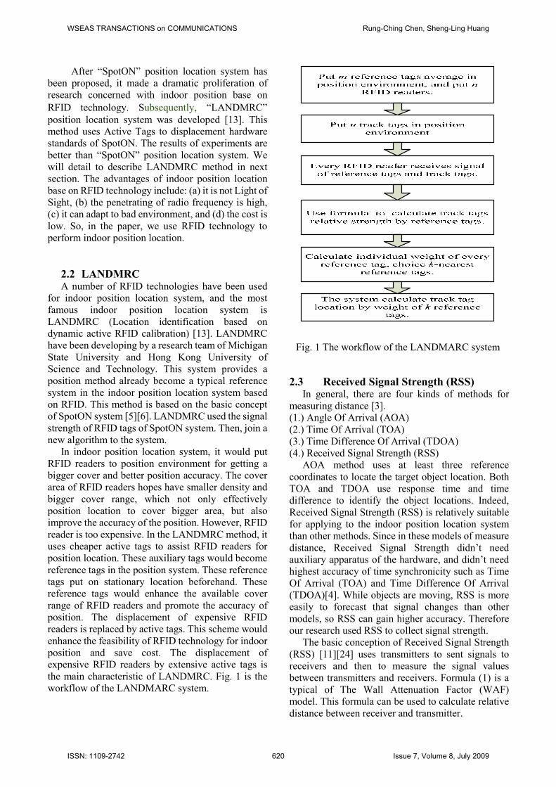
the main characteristic of LANDMRC. Fig. 1 is the
workflow of the LANDMARC system.
Fig. 1 The workflow of the LANDMARC system
2.3 Received Signal Strength (RSS) In general, there are four kinds of methods for
measuring distance [3].
(1.) Angle Of Arrival (AOA)
(2.) Time Of Arrival (TOA)
(3.) Time Difference Of Arrival (TDOA)
(4.) Received Signal Strength (RSS)
AOA method uses at least three reference
coordinates to locate the target object location. Both
TOA and TDOA use response time and time
difference to identify the object locations. Indeed,
Received Signal Strength (RSS) is relatively suitable
for applying to the indoor position location system
than other methods. Since in these models of measure
distance, Received Signal Strength didn’t need
auxiliary apparatus of the hardware, and didn’t need
highest accuracy of time synchronicity such as Time
Of Arrival (TOA) and Time Difference Of Arrival
(TDOA)[4]. While objects are moving, RSS is more
easily to forecast that signal changes than other
models, so RSS can gain higher accuracy. Therefore
our research used RSS to collect signal strength.
The basic conception of Received Signal Strength
(RSS) [11][24] uses transmitters to sent signals to
receivers and then to measure the signal values
between transmitters and receivers. Formula (1) is a
typical of The Wall Attenuation Factor (WAF)
model. This formula can be used to calculate relative
distance between receiver and transmitter.
WSEAS TRANSACTIONS on COMMUNICATIONS Rung-Ching Chen, Sheng-Ling Huang
ISSN: 1109-2742 620 Issue 7, Volume 8, July 2009
0
0
( ) ( ) 10 log
nW WAF nW CdPd Pd n
C WAF nW Cd
× < = − − × ≥
(1)
In the formula (1), P(d) is the signal intensity of
measurement at d distance. P(d0) is the signal
intensity at reference distance of d0. n is the factor of
fading. C is the maximum number of the attenuation
factor. W is quantity of the walls between transmitter
and base Station; nW is the number of walls between
the transmitter and the receiver and WAF is the
attenuation factor of wall.
2.4 The concept of Powel Level The electric wave transmission models of free
space that hypothesis of signal between transmitter
and receiver is no barrier on the path of Light of Sight
(LOS) communication [1]. The air-waves signal
transmission loss is related to distance between
transmitter and receiver. The Friis free - space
formula derives from the electric wave transmission
model of free space. Formula (2) is the Friis free -
space formula [6]. This formula can calculate the
relative distance between transmitter and receiver.
2
( )4
r t t rP d PGGd
λπ
=
(2)
In formula (2), Pr(d) is the received power. Pt is
the transmited power. Gt is the antenna gain of the
transmitter. Gr is the antenna gain of the receiver. λ
is the wavelength. d is the distance between
transmitter and receiver. In the formula (2), except d
is an unknown value, other parameters can be
measured work act known value. So we can use
received signals intensity to substitute formula (2) to
calculate distance between transmitter and receiver.
The relation of signal intensity and distance is
inversely proportional. For this reason, formula (3) is
derived from the range of reading of RFID reader
[10][16] which is based on Friis free - space,
4
t r t
th
PG Gr
P
τλπ
= (3)
In the formula (3), r is the effective reading range
of RFID readers. λ , Pt, Gr, and Gt are the same as
formula (2). τ is the coefficient of transmitting
power. Pth is the touch off the minimum energy
threshold value of RFID Tag chips. We detect r
values from formula (3). The RFID readers can
change effective reading range of RFID readers by
tuning control of transmit power of readers. As
LANDMRC, the authors used Spider System from
RF Code Company to accomplish their prototype
system on this condition that readers can change
effective reading range. RFID readers of LANDMRC
system used tuning control of reading range by eight
of increment instruction to control reading range and
used API to accomplish the controlling of read range.
Therefore, system could set up switch power level
continuously to change reading range while readers
read signal from tags. Make the readers to neglect or
to receive ID information from tags to control system
[7].
With the concept of this system, readers can
enhance or reduce read range by control the power
level. Relatively, these power levels make parameter
of relative distance. In order to use signal fading
models to calculate relative distance between reader
and tag, some RFID systems have provided the
function of reading signal intensity of tags directly.
Basis on Friss free - space concept, we can figure out
formula (4) by the signal fading models.
( ) ( ) 10 logo
o
dPL d PL d N WAF
d
= − −
(4)
PL(d) is the signal intensity at d distance. PL(d0) is
the signal intensity at reference distance of d0. d0 is
the segment distance between reader and reference
tag. N is the factor of fading; it usually changes by the
altered of the environment. While the environment
has big interference, the value of N would be big. In
general, the value of N is between 2 and 5. WAF
(Wall Attenuation Factor) is the attenuation factor of
wall, and one wall bring about between 3db and 15db
fading of signal intensity. By signal fading models of
formula (4) to divide the area of Power Level, it let
system utilize the relation between signal intensity
and distance to set up threshold value of signal
intensity of Powel Level at the range of area. In the
related research of Power Level, ALS (Area Position
Scheme) [23] provided NAMING scheme. This
scheme provided a way to name concepts by Powel
Level, and then capture the rough information. In this
paper, we will utilize reference tags of the block
which derived from ALS to reach more accuracy
information of position location in the indoor
environment.
3 Research methodology
WSEAS TRANSACTIONS on COMMUNICATIONS Rung-Ching Chen, Sheng-Ling Huang
ISSN: 1109-2742 621 Issue 7, Volume 8, July 2009
3.1 Procedure of research In this paper, we will purpose a method to
combine Powel Level to analyze object location. The
procedure of the research is shown in Fig. 2. The
procedures have two parts, first part is the learning
phase, and second part is the locating phase.
As follows, we would specify the learning phase
and the locating phase individually.
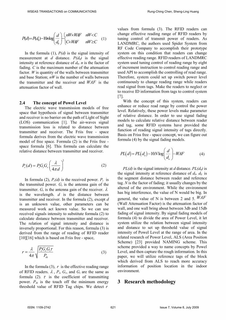
3.2 The learning phase The learning phase includes five steps explained
as follows.
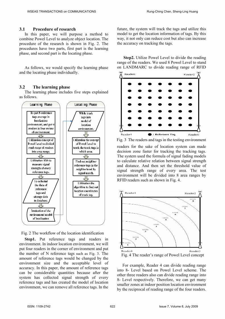
Step1. Put reference tags and readers in
environment. In indoor location environment, we will
put four readers in the corner of environment and put
the number of N reference tags such as Fig. 3. The
amount of reference tags would be changed by the
environment size and the acceptable level of
accuracy. In this paper, the amount of reference tags
can be considerable quantities because after the
system has collected signal strength of every
reference tags and has created the model of location
environment, we can remove all reference tags. In the
future, the system will track the tags and utilize this
model to get the location information of tags. By this
way, it not only can reduce cost but also can increase
the accuracy on tracking the tags.
Step2. Utilize Powel Level to divide the reading
range of the readers. We used 8 Powel Level to stand
on LANDMARC to divide reading range of RFID
readers for the sake of location system can made
decision zone faster for tracking the tracking tags.
The system used the formula of signal fading models
to calculate relative relation between signal strength
and distance. And then set the threshold value of
signal strength range of every area. The test
environment will be divided into 8 area ranges by
RFID readers such as shown in Fig. 4.
For example, Reader 4 can divide reading range
into 8- Level based on Powel Level scheme. The
other three readers also can divide reading range into
8- Level respectively. Therefore, we can get many
smaller zones at indoor position location environment
by the reciprocal of reading range of the four readers.
Fig. 2 The workflow of the location identification
Fig. 3 The readers and tags in the testing environment
Fig. 4 The reader’s range of Powel Level concept
WSEAS TRANSACTIONS on COMMUNICATIONS Rung-Ching Chen, Sheng-Ling Huang
ISSN: 1109-2742 622 Issue 7, Volume 8, July 2009
At these zones, we used NAMING scheme based on
ALS (Area Position Scheme) to define data type that
in accordance with relative four readers in turn to
record of a four-dimensional values
1 2 3 4( , , , )R R R RP P P P [23]. An example shows in Fig. 5.
When space zone at 5762 zone, it means the Reader 1
read level is at the reading range Level 5; the Reader 2
reading level is at the reading range Level 7; the
Reader 3 reading level is at the read range Level 6 and
the Reader 4 reading level is at the read range Level
2. This scheme can get a rational position range fast.
So, it locates an area easy but the accuracy is not
good.
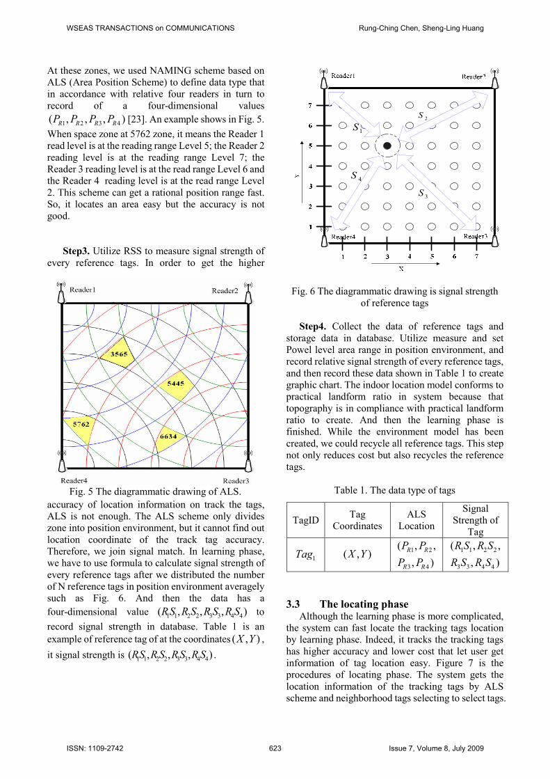
Step3. Utilize RSS to measure signal strength of
every reference tags. In order to get the higher
accuracy of location information on track the tags,
ALS is not enough. The ALS scheme only divides
zone into position environment, but it cannot find out
location coordinate of the track tag accuracy.
Therefore, we join signal match. In learning phase,
we have to use formula to calculate signal strength of
every reference tags after we distributed the number
of N reference tags in position environment averagely
such as Fig. 6. And then the data has a
four-dimensional value 1 1 2 2 3 3 4 4( , , , )RS R S R S R S to
record signal strength in database. Table 1 is an
example of reference tag of at the coordinates ( , )X Y ,
it signal strength is 1 1 2 2 3 3 4 4( , , , )RS RS RS R S .
Step4. Collect the data of reference tags and
storage data in database. Utilize measure and set
Powel level area range in position environment, and
record relative signal strength of every reference tags,
and then record these data shown in Table 1 to create
graphic chart. The indoor location model conforms to
practical landform ratio in system because that
topography is in compliance with practical landform
ratio to create. And then the learning phase is
finished. While the environment model has been
created, we could recycle all reference tags. This step
not only reduces cost but also recycles the reference
tags.
Table 1. The data type of tags
3.3 The locating phase Although the learning phase is more complicated,
the system can fast locate the tracking tags location
by learning phase. Indeed, it tracks the tracking tags
has higher accuracy and lower cost that let user get
information of tag location easy. Figure 7 is the
procedures of locating phase. The system gets the
location information of the tracking tags by ALS
scheme and neighborhood tags selecting to select tags.
Fig. 5 The diagrammatic drawing of ALS.
1S2
S
3S
4S
Fig. 6 The diagrammatic drawing is signal strength
of reference tags
TagID Tag
Coordinates
ALS
Location
Signal
Strength of
Tag
1Tag ( , )X Y 1 2
3 4
( , ,
, )
R R
R R
P P
P P
1 1 2 2
3 3 4 4
( , ,
, )
R S R S
R S R S
WSEAS TRANSACTIONS on COMMUNICATIONS Rung-Ching Chen, Sheng-Ling Huang
ISSN: 1109-2742 623 Issue 7, Volume 8, July 2009
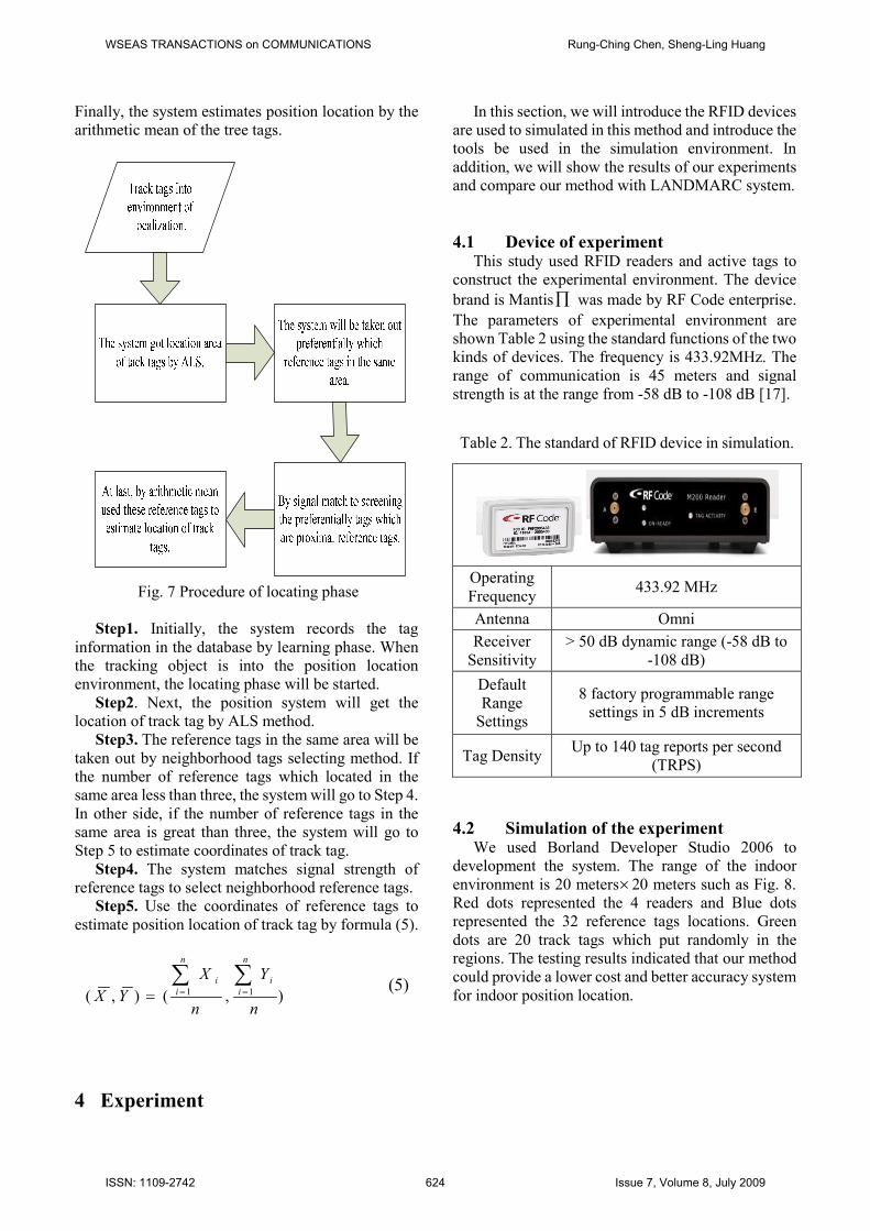
Finally, the system estimates position location by the
arithmetic mean of the tree tags.
Fig. 7 Procedure of locating phase
Step1. Initially, the system records the tag
information in the database by learning phase. When
the tracking object is into the position location
environment, the locating phase will be started.
Step2. Next, the position system will get the
location of track tag by ALS method.
Step3. The reference tags in the same area will be
taken out by neighborhood tags selecting method. If
the number of reference tags which located in the
same area less than three, the system will go to Step 4.
In other side, if the number of reference tags in the
same area is great than three, the system will go to
Step 5 to estimate coordinates of track tag.
Step4. The system matches signal strength of
reference tags to select neighborhood reference tags.
Step5. Use the coordinates of reference tags to
estimate position location of track tag by formula (5).
1 1( , ) ( , )
n n
i i
i i
X Y
X Yn n
= ==∑ ∑
(5)
4 Experiment
In this section, we will introduce the RFID devices
are used to simulated in this method and introduce the
tools be used in the simulation environment. In
addition, we will show the results of our experiments
and compare our method with LANDMARC system.
4.1 Device of experiment This study used RFID readers and active tags to
construct the experimental environment. The device
brand is Mantis∏ was made by RF Code enterprise.
The parameters of experimental environment are
shown Table 2 using the standard functions of the two
kinds of devices. The frequency is 433.92MHz. The
range of communication is 45 meters and signal
strength is at the range from -58 dB to -108 dB [17].
Table 2. The standard of RFID device in simulation.
Operating
Frequency 433.92 MHz
Antenna Omni
Receiver
Sensitivity
> 50 dB dynamic range (-58 dB to
-108 dB)
Default
Range
Settings
8 factory programmable range
settings in 5 dB increments
Tag Density Up to 140 tag reports per second
(TRPS)
4.2 Simulation of the experiment We used Borland Developer Studio 2006 to
development the system. The range of the indoor
environment is 20 meters×20 meters such as Fig. 8.
Red dots represented the 4 readers and Blue dots
represented the 32 reference tags locations. Green
dots are 20 track tags which put randomly in the
regions. The testing results indicated that our method
could provide a lower cost and better accuracy system
for indoor position location.
WSEAS TRANSACTIONS on COMMUNICATIONS Rung-Ching Chen, Sheng-Ling Huang
ISSN: 1109-2742 624 Issue 7, Volume 8, July 2009
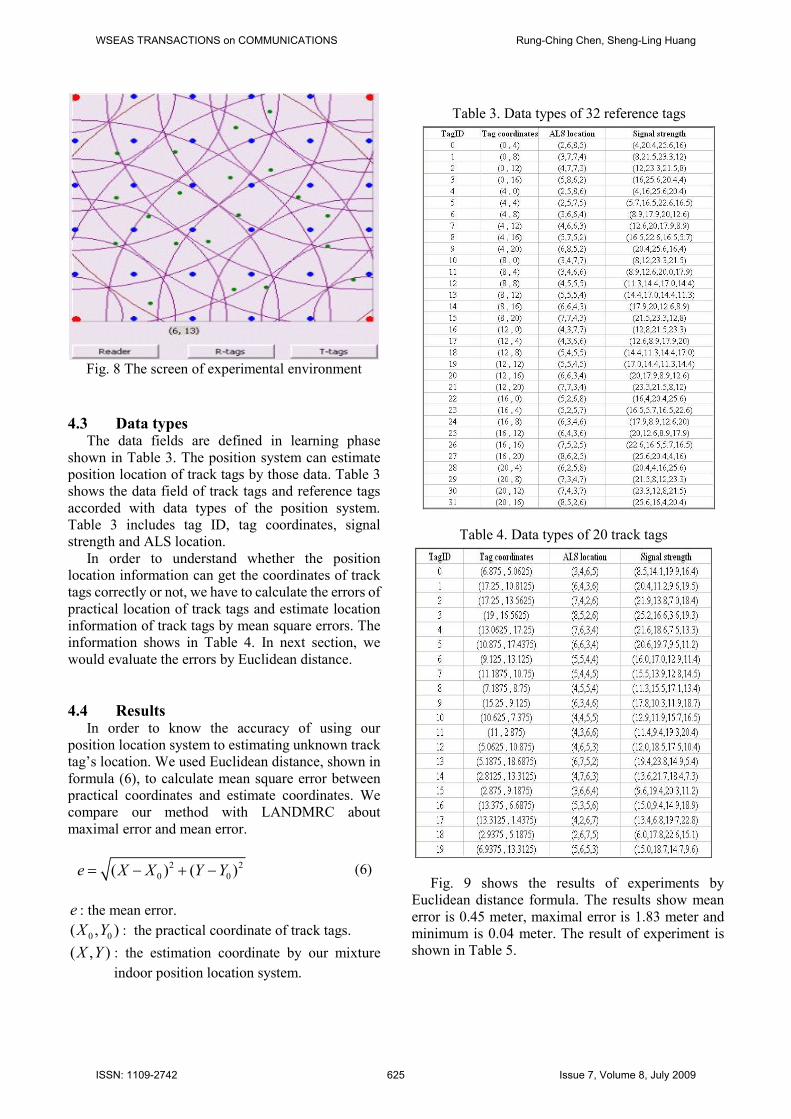
Fig. 8 The screen of experimental environment
4.3 Data types The data fields are defined in learning phase
shown in Table 3. The position system can estimate
position location of track tags by those data. Table 3
shows the data field of track tags and reference tags
accorded with data types of the position system.
Table 3 includes tag ID, tag coordinates, signal
strength and ALS location.
In order to understand whether the position
location information can get the coordinates of track
tags correctly or not, we have to calculate the errors of
practical location of track tags and estimate location
information of track tags by mean square errors. The
information shows in Table 4. In next section, we
would evaluate the errors by Euclidean distance.
4.4 Results In order to know the accuracy of using our
position location system to estimating unknown track
tag’s location. We used Euclidean distance, shown in
formula (6), to calculate mean square error between
practical coordinates and estimate coordinates. We
compare our method with LANDMRC about
maximal error and mean error.
2 2
0 0( ) ( )e X X Y Y= − + − (6)
e : the mean error.
0 0( , )X Y : the practical coordinate of track tags.
( , )X Y : the estimation coordinate by our mixture
indoor position location system.
Table 4. Data types of 20 track tags
Fig. 9 shows the results of experiments by
Euclidean distance formula. The results show mean
error is 0.45 meter, maximal error is 1.83 meter and
minimum is 0.04 meter. The result of experiment is
shown in Table 5.
Table 3. Data types of 32 reference tags
WSEAS TRANSACTIONS on COMMUNICATIONS Rung-Ching Chen, Sheng-Ling Huang
ISSN: 1109-2742 625 Issue 7, Volume 8, July 2009
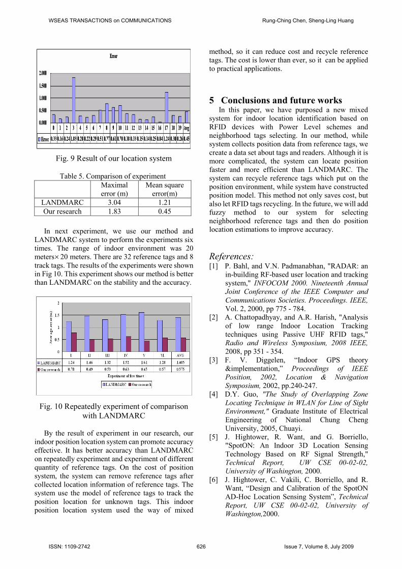
Fig. 9 Result of our location system
Table 5. Comparison of experiment
Maximal
error (m)
Mean square
error(m)
LANDMARC 3.04 1.21
Our research 1.83 0.45
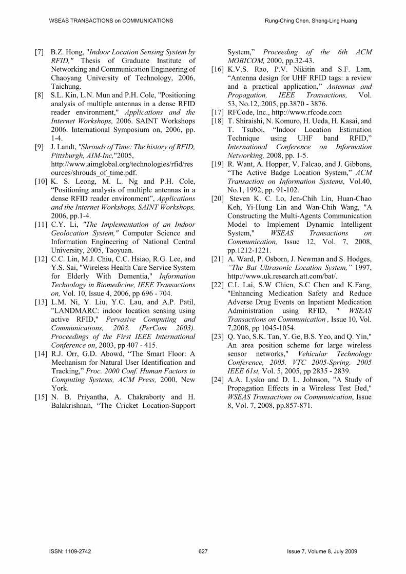
In next experiment, we use our method and
LANDMARC system to perform the experiments six
times. The range of indoor environment was 20
meters×20 meters. There are 32 reference tags and 8
track tags. The results of the experiments were shown
in Fig 10. This experiment shows our method is better
than LANDMARC on the stability and the accuracy.
Fig. 10 Repeatedly experiment of comparison
with LANDMARC
By the result of experiment in our research, our
indoor position location system can promote accuracy
effective. It has better accuracy than LANDMARC
on repeatedly experiment and experiment of different
quantity of reference tags. On the cost of position
system, the system can remove reference tags after
collected location information of reference tags. The
system use the model of reference tags to track the
position location for unknown tags. This indoor
position location system used the way of mixed
method, so it can reduce cost and recycle reference
tags. The cost is lower than ever, so it can be applied
to practical applications.
5 Conclusions and future works In this paper, we have purposed a new mixed
system for indoor location identification based on
RFID devices with Power Level schemes and
neighborhood tags selecting. In our method, while
system collects position data from reference tags, we
create a data set about tags and readers. Although it is
more complicated, the system can locate position
faster and more efficient than LANDMARC. The
system can recycle reference tags which put on the
position environment, while system have constructed
position model. This method not only saves cost, but
also let RFID tags recycling. In the future, we will add
fuzzy method to our system for selecting
neighborhood reference tags and then do position
location estimations to improve accuracy.
References: [1] P. Bahl, and V.N. Padmanabhan, "RADAR: an
in-building RF-based user location and tracking
system," INFOCOM 2000. Nineteenth Annual
Joint Conference of the IEEE Computer and
Communications Societies. Proceedings. IEEE,
Vol. 2, 2000, pp 775 - 784.
[2] A. Chattopadhyay, and A.R. Harish, "Analysis
of low range Indoor Location Tracking
techniques using Passive UHF RFID tags,"
Radio and Wireless Symposium, 2008 IEEE,
2008, pp 351 - 354.
[3] F. V. Diggelen, “Indoor GPS theory
&implementation,” Proceedings of IEEE
Position, 2002, Location & Navigation
Symposium, 2002, pp.240-247.
[4] D.Y. Guo, "The Study of Overlapping Zone
Locating Technique in WLAN for Line of Sight
Environment," Graduate Institute of Electrical
Engineering of National Chung Cheng
University, 2005, Chuayi.
[5] J. Hightower, R. Want, and G. Borriello,
"SpotON: An Indoor 3D Location Sensing
Technology Based on RF Signal Strength,"
Technical Report, UW CSE 00-02-02,
University of Washington, 2000.
[6] J. Hightower, C. Vakili, C. Borriello, and R.
Want, “Design and Calibration of the SpotON
AD-Hoc Location Sensing System”, Technical
Report, UW CSE 00-02-02, University of
Washington,2000.
WSEAS TRANSACTIONS on COMMUNICATIONS Rung-Ching Chen, Sheng-Ling Huang
ISSN: 1109-2742 626 Issue 7, Volume 8, July 2009
[7] B.Z. Hong, "Indoor Location Sensing System by
RFID," Thesis of Graduate Institute of
Networking and Communication Engineering of
Chaoyang University of Technology, 2006,
Taichung.
[8] S.L. Kin, L.N. Mun and P.H. Cole, "Positioning
analysis of multiple antennas in a dense RFID
reader environment," Applications and the
Internet Workshops, 2006. SAINT Workshops
2006. International Symposium on, 2006, pp.
1-4.
[9] J. Landt, "Shrouds of Time: The history of RFID,
Pittsburgh, AIM-Inc,"2005,
http://www.aimglobal.org/technologies/rfid/res
ources/shrouds_of_time.pdf.
[10] K. S. Leong, M. L. Ng and P.H. Cole,
“Positioning analysis of multiple antennas in a
dense RFID reader environment”, Applications
and the Internet Workshops, SAINT Workshops,
2006, pp.1-4.
[11] C.Y. Li, "The Implementation of an Indoor
Geolocation System," Computer Science and
Information Engineering of National Central
University, 2005, Taoyuan.
[12] C.C. Lin, M.J. Chiu, C.C. Hsiao, R.G. Lee, and
Y.S. Sai, "Wireless Health Care Service System
for Elderly With Dementia," Information
Technology in Biomedicine, IEEE Transactions
on, Vol. 10, Issue 4, 2006, pp 696 - 704.
[13] L.M. Ni, Y. Liu, Y.C. Lau, and A.P. Patil,
"LANDMARC: indoor location sensing using
active RFID," Pervasive Computing and
Communications, 2003. (PerCom 2003).
Proceedings of the First IEEE International
Conference on, 2003, pp 407 - 415.
[14] R.J. Orr, G.D. Abowd, “The Smart Floor: A
Mechanism for Natural User Identification and
Tracking,” Proc. 2000 Conf. Human Factors in
Computing Systems, ACM Press, 2000, New
York.
[15] N. B. Priyantha, A. Chakraborty and H.
Balakrishnan, “The Cricket Location-Support
System,” Proceeding of the 6th ACM
MOBICOM, 2000, pp.32-43.
[16] K.V.S. Rao, P.V. Nikitin and S.F. Lam,
“Antenna design for UHF RFID tags: a review
and a practical application,” Antennas and
Propagation, IEEE Transactions, Vol.
53, No.12, 2005, pp.3870 - 3876.
[17] RFCode, Inc., http://www.rfcode.com
[18] T. Shiraishi, N. Komuro, H. Ueda, H. Kasai, and
T. Tsuboi, “Indoor Location Estimation
Technique using UHF band RFID,”
International Conference on Information
Networking, 2008, pp. 1-5.
[19] R. Want, A. Hopper, V. Falcao, and J. Gibbons,
“The Active Badge Location System,” ACM
Transaction on Information Systems, Vol.40,
No.1, 1992, pp. 91-102.
[20] Steven K. C. Lo, Jen-Chih Lin, Huan-Chao
Keh, Yi-Hung Lin and Wan-Chih Wang, "A
Constructing the Multi-Agents Communication
Model to Implement Dynamic Intelligent
System," WSEAS Transactions on
Communication, Issue 12, Vol. 7, 2008,
pp.1212-1221.
[21] A. Ward, P. Osborn, J. Newman and S. Hodges,
“The Bat Ultrasonic Location System,” 1997,
http://www.uk.research.att.com/bat/.
[22] C.L Lai, S.W Chien, S.C Chen and K.Fang,
"Enhancing Medication Safety and Reduce
Adverse Drug Events on Inpatient Medication
Administration using RFID, " WSEAS
Transactions on Communication , Issue 10, Vol.
7,2008, pp 1045-1054.
[23] Q. Yao, S.K. Tan, Y. Ge, B.S. Yeo, and Q. Yin,"
An area position scheme for large wireless
sensor networks," Vehicular Technology
Conference, 2005. VTC 2005-Spring. 2005
IEEE 61st, Vol. 5, 2005, pp 2835 - 2839.
[24] A.A. Lysko and D. L. Johnson, "A Study of
Propagation Effects in a Wireless Test Bed,"
WSEAS Transactions on Communication, Issue
8, Vol. 7, 2008, pp.857-871.
WSEAS TRANSACTIONS on COMMUNICATIONS Rung-Ching Chen, Sheng-Ling Huang
ISSN: 1109-2742 627 Issue 7, Volume 8, July 2009