Embed Size (px)
Citation preview
www.rfsworld.com390
5
WIR
ELES
SIN
DO
OR
SOLU
TIO
NS
Introduction to RADIAFLEX®
Wireless Indoor Solutions
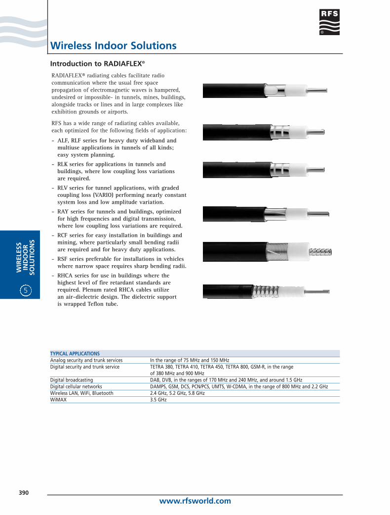
RADIAFLEX® radiating cables facilitate radiocommunication where the usual free spacepropagation of electromagnetic waves is hampered,undesired or impossible- in tunnels, mines, buildings,alongside tracks or lines and in large complexes likeexhibition grounds or airports.
RFS has a wide range of radiating cables available,each optimized for the following fields of application:
- ALF, RLF series for heavy duty wideband and multiuse applications in tunnels of all kinds; easy system planning.
- RLK series for applications in tunnels andbuildings, where low coupling loss variations are required.
- RLV series for tunnel applications, with gradedcoupling loss (VARIO) performing nearly constantsystem loss and low amplitude variation.
- RAY series for tunnels and buildings, optimizedfor high frequencies and digital transmission,where low coupling loss variations are required.
- RCF series for easy installation in buildings andmining, where particularly small bending radiiare required and for heavy duty applications.
- RSF series preferable for installations in vehicleswhere narrow space requires sharp bending radii.
- RHCA series for use in buildings where the highest level of fire retardant standards arerequired. Plenum rated RHCA cables utilize an air-dielectric design. The dielectric support is wrapped Teflon tube.
TYPICAL APPLICATIONSAnalog security and trunk services In the range of 75 MHz and 150 MHzDigital security and trunk service TETRA 380, TETRA 410, TETRA 450, TETRA 800, GSM-R, in the range
of 380 MHz and 900 MHzDigital broadcasting DAB, DVB, in the ranges of 170 MHz and 240 MHz, and around 1.5 GHzDigital cellular networks DAMPS, GSM, DCS, PCN/PCS, UMTS, W-CDMA, in the range of 800 MHz and 2.2 GHzWireless LAN, WiFi, Bluetooth 2.4 GHz, 5.2 GHz, 5.8 GHzWiMAX 3.5 GHz
www.rfsworld.com391
WIR
ELESSIN
DO
OR
SOLU
TION
S
5
How to Select the Best SuitedRADIAFLEX® Cable for a Given Purpose
Wireless Indoor Solutions
All RADIAFLEX® cables belong to one of these sizes.For a given size, all smooth wall RADIAFLEX® cableshave the same basic structure of inner conductor,foam dielectric, copper strip outer conductor andjacket, thus allowing identical connectors and clampsto be used (except of the RCF/RSF series and RHCAseries with their corrugated outer conductor).
The differences between the cable versions of one given nominal diameter are solely attributable to the configuration of the outer conductor apertures. This configuration determines the kind of interactionbetween the inner coaxial system and the outsideenvironment, and thus it influences all the cable'simportant electrical parameters like frequency range, attenuation, coupling loss, reflection factorand susceptibility to environmental conditions (such as lossy walls, accumulation of dust or salt and moisture etc.).
The best suited cable would have optimum values for all of these parameters, and knowing the particularapplication (service length, frequency range ofoperation etc.), this best suited cable can be determined.Following are a few indications about that. Thecomparisons are made for achieving minimum systemloss, i.e. minimum of the sum of attenuation andcoupling loss, and for maximum useful length.
EACH RADIAFLEX® CABLE IS CLASSIFIED ACCORDING TO ITS NOMINAL DIELECTRIC DIAMETER 1/2" 11 mm ALF 12-50 RLK 12-50 RCF/RSF 12-50 RHCA 12-50*7/8" 23 mm RLF 78-50 RLK 78-50 RAY 78-50 RCF 78-501 1/4" 33 mm RLF 114-50 RLK 114-50 RLV 114-50 RAY 114-50 RCF 114-501 5/8" 44 mm RLF 158-50 RLK 158-50 RLV 158-50 RAY 158-50 RCF 158-50For a given nominal diameter, connectors and clamps are the same for any cable type (exemption: types RCF/RSF and RHCA).* Plenum rated version (JPL) only.
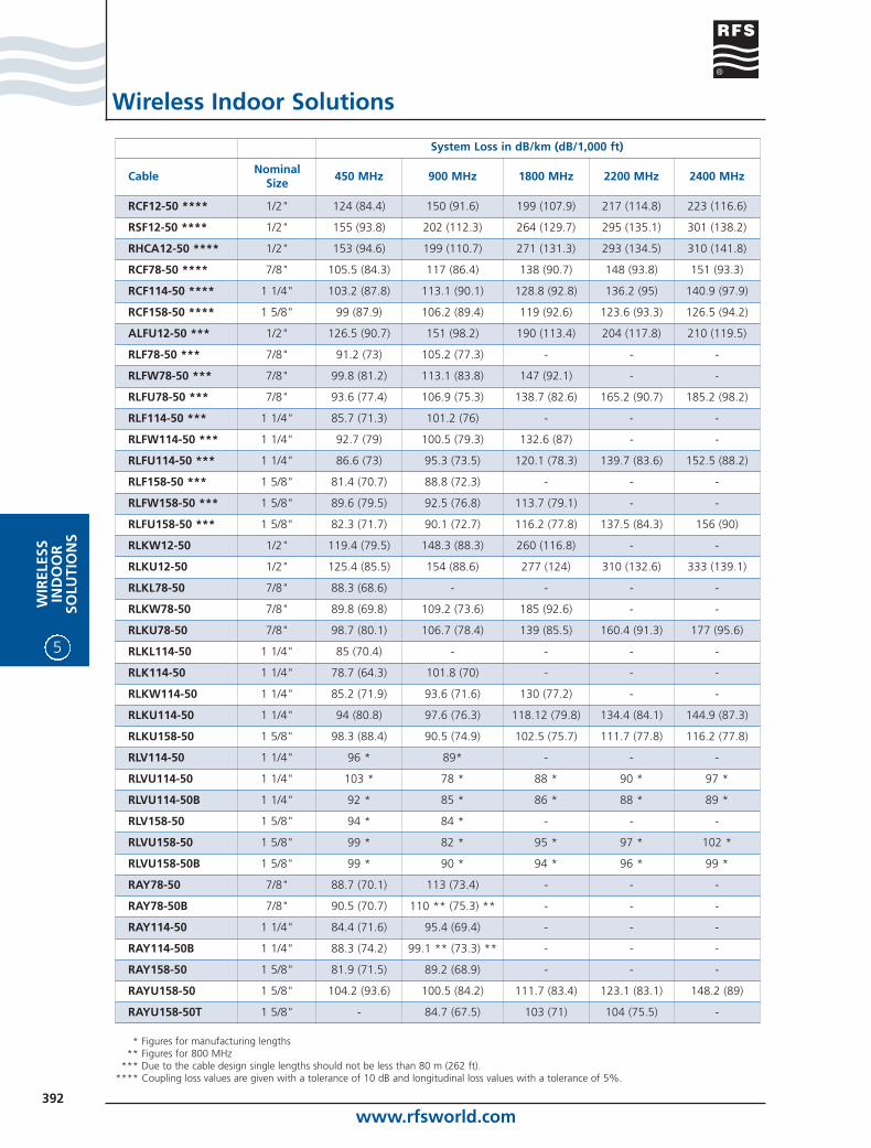
RLK U 78-50 XXX A
Jacket types: J, JFN, JFL
Impedance
Size, e.g. 7/8”
w/o suffix: up to 900 MHz bandL: up to 600 MHz bandW: up to 1900 MHz bandU: up to 2200 MHz band
and aboveCable type
www.rfsworld.com392
5
WIR
ELES
SIN
DO
OR
SOLU
TIO
NS
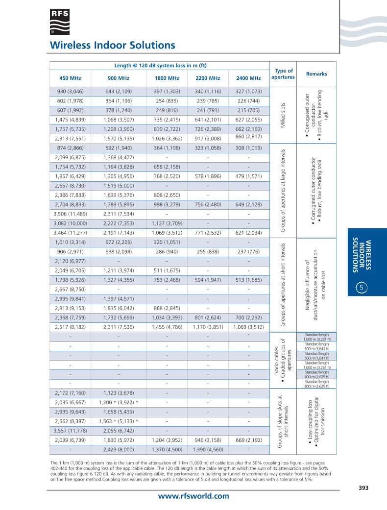
NominalSize
Cable 450 MHz 900 MHz 1800 MHz 2200 MHz 2400 MHz
1/2"RCF12-50 **** 124 (84.4) 150 (91.6) 199 (107.9) 217 (114.8) 223 (116.6)
1/2"RSF12-50 **** 155 (93.8) 202 (112.3) 264 (129.7) 295 (135.1) 301 (138.2)
1/2"RHCA12-50 **** 153 (94.6) 199 (110.7) 271 (131.3) 293 (134.5) 310 (141.8)
7/8"RCF78-50 **** 105.5 (84.3) 117 (86.4) 138 (90.7) 148 (93.8) 151 (93.3)
1 1/4"RCF114-50 **** 103.2 (87.8) 113.1 (90.1) 128.8 (92.8) 136.2 (95) 140.9 (97.9)
1 5/8"RCF158-50 **** 99 (87.9) 106.2 (89.4) 119 (92.6) 123.6 (93.3) 126.5 (94.2)
1/2"ALFU12-50 *** 126.5 (90.7) 151 (98.2) 190 (113.4) 204 (117.8) 210 (119.5)
7/8"RLF78-50 *** 91.2 (73) 105.2 (77.3) - - -
7/8"RLFW78-50 *** 99.8 (81.2) 113.1 (83.8) 147 (92.1) - -
7/8"RLFU78-50 *** 93.6 (77.4) 106.9 (75.3) 138.7 (82.6) 165.2 (90.7) 185.2 (98.2)
1 1/4"RLF114-50 *** 85.7 (71.3) 101.2 (76) - - -
1 1/4"RLFW114-50 *** 92.7 (79) 100.5 (79.3) 132.6 (87) - -
1 1/4"RLFU114-50 *** 86.6 (73) 95.3 (73.5) 120.1 (78.3) 139.7 (83.6) 152.5 (88.2)
1 5/8"RLF158-50 *** 81.4 (70.7) 88.8 (72.3) - - -
1 5/8"RLFW158-50 *** 89.6 (79.5) 92.5 (76.8) 113.7 (79.1) - -
1 5/8"RLFU158-50 *** 82.3 (71.7) 90.1 (72.7) 116.2 (77.8) 137.5 (84.3) 156 (90)
1/2"RLKW12-50 119.4 (79.5) 148.3 (88.3) 260 (116.8) - -
1/2"RLKU12-50 125.4 (85.5) 154 (88.6) 277 (124) 310 (132.6) 333 (139.1)
7/8"RLKL78-50 88.3 (68.6) - - - -
7/8"RLKW78-50 89.8 (69.8) 109.2 (73.6) 185 (92.6) - -
7/8"RLKU78-50 98.7 (80.1) 106.7 (78.4) 139 (85.5) 160.4 (91.3) 177 (95.6)
1 1/4"RLKL114-50 85 (70.4) - - - -
1 1/4"RLK114-50 78.7 (64.3) 101.8 (70) - - -
1 1/4"RLKW114-50 85.2 (71.9) 93.6 (71.6) 130 (77.2) - -
1 1/4"RLKU114-50 94 (80.8) 97.6 (76.3) 118.12 (79.8) 134.4 (84.1) 144.9 (87.3)
1 5/8"RLKU158-50 98.3 (88.4) 90.5 (74.9) 102.5 (75.7) 111.7 (77.8) 116.2 (77.8)
1 1/4"RLV114-50 96 * 89* - - -
1 1/4"RLVU114-50 103 * 78 * 88 * 90 * 97 *
1 1/4"RLVU114-50B 92 * 85 * 86 * 88 * 89 *
1 5/8"RLV158-50 94 * 84 * - - -
1 5/8"RLVU158-50 99 * 82 * 95 * 97 * 102 *
1 5/8"RLVU158-50B 99 * 90 * 94 * 96 * 99 *
7/8"RAY78-50 88.7 (70.1) 113 (73.4) - - -
7/8"RAY78-50B 90.5 (70.7) 110 ** (75.3) ** - - -
1 1/4"RAY114-50 84.4 (71.6) 95.4 (69.4) - - -
1 1/4"RAY114-50B 88.3 (74.2) 99.1 ** (73.3) ** - - -
1 5/8"RAY158-50 81.9 (71.5) 89.2 (68.9) - - -
1 5/8"RAYU158-50 104.2 (93.6) 100.5 (84.2) 111.7 (83.4) 123.1 (83.1) 148.2 (89)
1 5/8"RAYU158-50T - 84.7 (67.5) 103 (71) 104 (75.5) -
Wireless Indoor Solutions
* Figures for manufacturing lengths** Figures for 800 MHz
*** Due to the cable design single lengths should not be less than 80 m (262 ft).**** Coupling loss values are given with a tolerance of 10 dB and longitudinal loss values with a tolerance of 5%.
System Loss in dB/km (dB/1,000 ft)
www.rfsworld.com393
WIR
ELESSIN
DO
OR
SOLU
TION
S
5
450 MHz 900 MHz 1800 MHz 2200 MHz 2400 MHz
930 (3,046) 643 (2,109) 397 (1,303) 340 (1,116) 327 (1,073)
602 (1,978) 364 (1,196) 254 (835) 239 (785) 226 (744)
607 (1,992) 378 (1,240) 249 (816) 241 (791) 215 (705)
1,475 (4,839) 1,068 (3,507) 735 (2,415) 641 (2,101) 627 (2,055)
1,757 (5,735) 1,208 (3,960) 830 (2,722) 726 (2,389) 662 (2,169)
2,313 (7,551) 1,570 (5,135) 1,026 (3,362) 917 (3,008) 860 (2,817)
874 (2,866) 592 (1,940) 364 (1,198) 323 (1,058) 308 (1,013)
2,099 (6,875) 1,368 (4,472) - - -
1,754 (5,732) 1,164 (3,828) 658 (2,158) - -
1,957 (6,429) 1,305 (4,956) 768 (2,520) 578 (1,896) 479 (1,571)
2,657 (8,730) 1,519 (5,000) - - -
2,386 (7,833) 1,639 (5,376) 808 (2,650) - -
2,704 (8,833) 1,789 (5,895) 998 (3,279) 756 (2,480) 649 (2,128)
3,506 (11,489) 2,311 (7,534) - - -
3,082 (10,000) 2,222 (7,353) 1,127 (3,709) - -
3,464 (11,277) 2,191 (7,143) 1,069 (3,512) 771 (2,532) 621 (2,034)
1,010 (3,314) 672 (2,205) 320 (1,051) - -
906 (2,971) 638 (2,098) 286 (940) 255 (838) 237 (776)
2,120 (6,977) - - - -
2,049 (6,705) 1,211 (3,974) 511 (1,675) - -
1,798 (5,926) 1,327 (4,355) 753 (2,468) 594 (1,947) 513 (1,685)
2,667 (8,750) - - - -
2,995 (9,841) 1,397 (4,571) - - -
2,813 (9,153) 1,835 (6,042) 868 (2,845) - -
2,368 (7,759) 1,732 (5,699) 1,034 (3,393) 801 (2,624) 700 (2,292)
2,517 (8,182) 2,311 (7,536) 1,455 (4,786) 1,170 (3,851) 1,069 (3,512)
- - - - -
- - - - -
- - - - -
- - - - -
- - - - -
- - - - -
2,172 (7,160) 1,123 (3,678) - - -
2,035 (6,667) 1,200 * (3,922) * - - -
2,935 (9,643) 1,658 (5,439) - - -
2,562 (8,387) 1,563 * (5,133) * - - -
3,557 (11,778) 2,055 (6,742) - - -
2,039 (6,739) 1,830 (5,972) 1,204 (3,952) 946 (3,158) 669 (2,192)
- 2,429 (8,000) 1,370 (4,500) 1,390 (4,560) -
Type ofapertures
Remarks
Mill
ed s
lots
• C
orru
gate
d ou
ter
cond
ucto
r•
Robu
st,
low
ben
ding
radi
i
Gro
ups
of a
pert
ures
at
larg
e in
terv
als
Gro
ups
of a
pert
ures
at
shor
t in
terv
als
Neg
ligib
le in
fluen
ce o
f
dust
/sal
t/m
oist
ure
accu
mul
atio
n
on c
able
loss
• C
orru
gate
d ou
ter
cond
ucto
r•
Robu
st,
low
ben
ding
rad
ii
Standard length1,000 m (3,281 ft)Standard length500 m (1,641 ft)Standard length500 m (1,641 ft)Standard length
1,000 m (3,281 ft)Standard length800 m (2,625 ft)Standard length800 m (2,625 ft)
• Lo
w c
oupl
ing
loss
• O
ptim
ized
for
dig
ital
tran
smis
sion
Vario
cab
les
• G
rade
d gr
oups
of
aper
ture
s
Gro
ups
of s
lope
slo
ts a
tsh
ort
inte
rval
s
Wireless Indoor Solutions
The 1 km (1,000 m) system loss is the sum of the attenuation of 1 km (1,000 m) of cable loss plus the 50% coupling loss figure - see pages402-440 for the coupling loss of the applicable cable. The 120 dB length is the cable length at which the sum of its attenuation and the 50%coupling loss figure is 120 dB. As with any radiating cable, the performance in building or tunnel environments may deviate from figures basedon the free space method.Coupling loss values are given with a tolerance of 5 dB and longitudinal loss values with a tolerance of 5%.
Length @ 120 dB system loss in m (ft)
www.rfsworld.com394
5
WIR
ELES
SIN
DO
OR
SOLU
TIO
NS
Flame and Fire Retardant Jackets
Wireless Indoor Solutions
The standard jacket material of all RADIAFLEX® cable is polyethylene, black. Those cable have the suffix Jand meet the requirement of:
• IEC 60 754-1 (halogen-free, <0.2% Chlorine), and
• IEC 60 754-2 (non-corrosive, PH-value > 4.3, conductivity < 100 mSiemens/cm).
Smooth wall RADIAFLEX® cable with the suffix JFNmeet the requirements of:
• IEC 60 754-1 and -2 (as above)
• IEC 60 332-1 (flame retardant, ‘single cable’), and
• IEC 60 332-3-24 (fire retardant, ‘cable bundle’).
Cable sizes of 1/2” and 5/8” meet in addition:
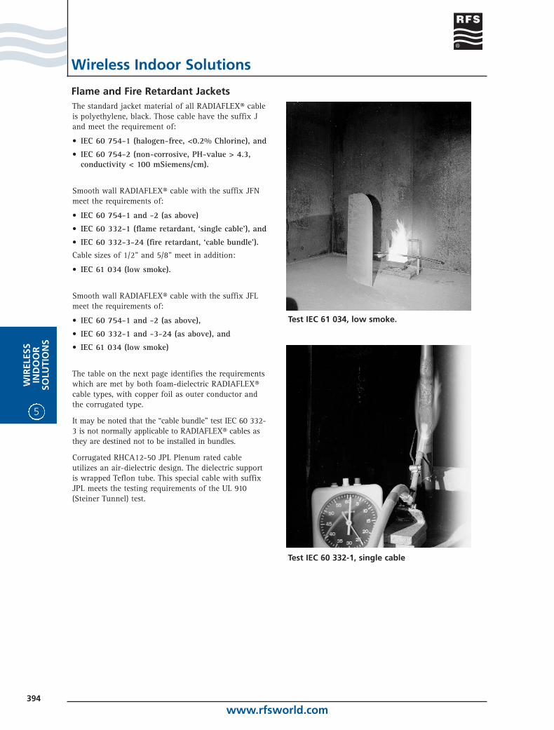
• IEC 61 034 (low smoke).
Smooth wall RADIAFLEX® cable with the suffix JFLmeet the requirements of:
• IEC 60 754-1 and -2 (as above),
• IEC 60 332-1 and -3-24 (as above), and
• IEC 61 034 (low smoke)
The table on the next page identifies the requirementswhich are met by both foam-dielectric RADIAFLEX®cable types, with copper foil as outer conductor and the corrugated type.
It may be noted that the “cable bundle” test IEC 60 332-3 is not normally applicable to RADIAFLEX® cables asthey are destined not to be installed in bundles.
Corrugated RHCA12-50 JPL Plenum rated cable utilizes an air-dielectric design. The dielectric support is wrapped Teflon tube. This special cable with suffixJPL meets the testing requirements of the UL 910(Steiner Tunnel) test.
Test IEC 61 034, low smoke.
Test IEC 60 332-1, single cable
www.rfsworld.com395
WIR
ELESSIN
DO
OR
SOLU
TION
S
5
Jackets Selection Guide
Wireless Indoor Solutions
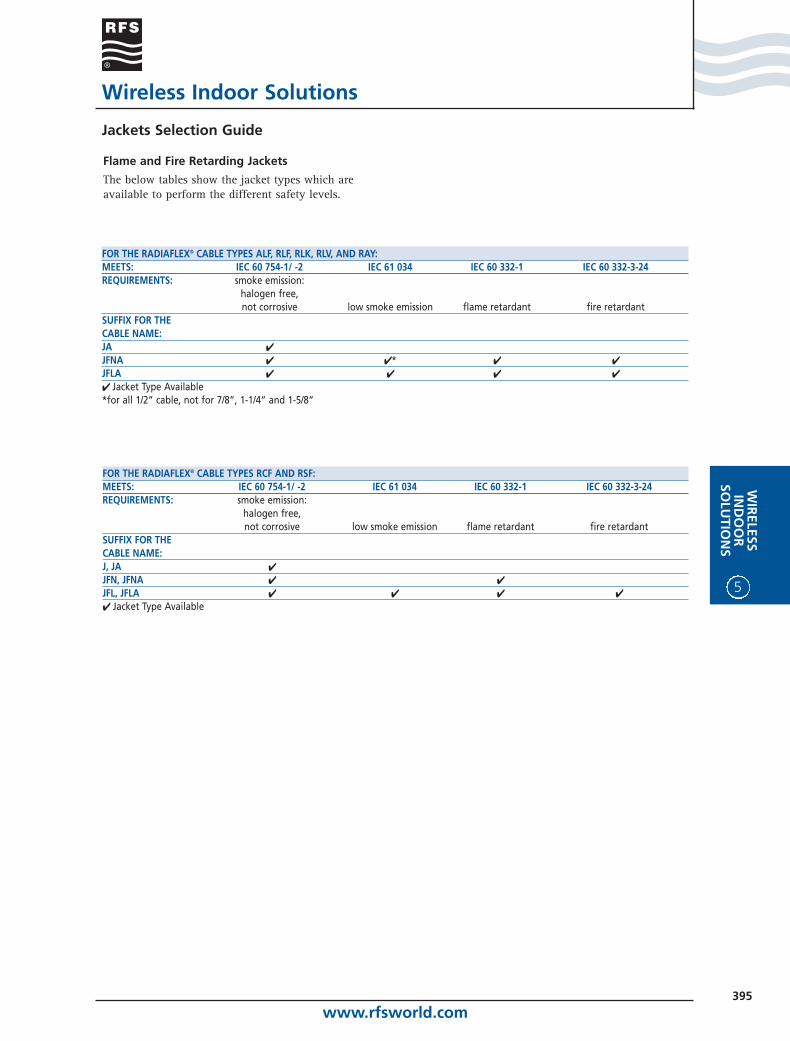
Flame and Fire Retarding Jackets
The below tables show the jacket types which areavailable to perform the different safety levels.
FOR THE RADIAFLEX® CABLE TYPES RCF AND RSF:MEETS: IEC 60 754-1/ -2 IEC 61 034 IEC 60 332-1 IEC 60 332-3-24REQUIREMENTS: smoke emission:
halogen free,not corrosive low smoke emission flame retardant fire retardant
SUFFIX FOR THECABLE NAME:J, JA ✔
JFN, JFNA ✔ ✔
JFL, JFLA ✔ ✔ ✔ ✔
✔ Jacket Type Available
FOR THE RADIAFLEX® CABLE TYPES ALF, RLF, RLK, RLV, AND RAY:MEETS: IEC 60 754-1/ -2 IEC 61 034 IEC 60 332-1 IEC 60 332-3-24REQUIREMENTS: smoke emission:
halogen free,not corrosive low smoke emission flame retardant fire retardant
SUFFIX FOR THECABLE NAME:JA ✔
JFNA ✔ ✔ * ✔ ✔
JFLA ✔ ✔ ✔ ✔
✔ Jacket Type Available*for all 1/2” cable, not for 7/8”, 1-1/4” and 1-5/8”
www.rfsworld.com396
5
WIR
ELES
SIN
DO
OR
SOLU
TIO
NS
Wireless Indoor Solutions
Description of Technical Parameters
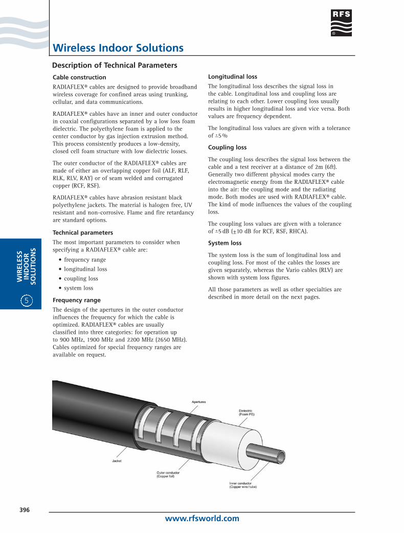
Cable construction
RADIAFLEX® cables are designed to provide broadbandwireless coverage for confined areas using trunking,cellular, and data communications.
RADIAFLEX® cables have an inner and outer conductorin coaxial configurations separated by a low loss foamdielectric. The polyethylene foam is applied to thecenter conductor by gas injection extrusion method.This process consistently produces a low-density, closed cell foam structure with low dielectric losses.
The outer conductor of the RADIAFLEX® cables aremade of either an overlapping copper foil (ALF, RLF,RLK, RLV, RAY) or of seam welded and corrugatedcopper (RCF, RSF).
RADIAFLEX® cables have abrasion resistant blackpolyethylene jackets. The material is halogen free, UVresistant and non-corrosive. Flame and fire retardancyare standard options.
Technical parameters
The most important parameters to consider whenspecifying a RADIAFLEX® cable are:
• frequency range
• longitudinal loss
• coupling loss
• system loss
Frequency range
The design of the apertures in the outer conductorinfluences the frequency for which the cable isoptimized. RADIAFLEX® cables are usually classified into three categories: for operation up to 900 MHz, 1900 MHz and 2200 MHz (2650 MHz).Cables optimized for special frequency ranges areavailable on request.
Longitudinal loss
The longitudinal loss describes the signal loss in the cable. Longitudinal loss and coupling loss arerelating to each other. Lower coupling loss usuallyresults in higher longitudinal loss and vice versa. Bothvalues are frequency dependent.
The longitudinal loss values are given with a toleranceof +_5 %
Coupling loss
The coupling loss describes the signal loss between thecable and a test receiver at a distance of 2m (6ft).Generally two different physical modes carry theelectromagnetic energy from the RADIAFLEX® cableinto the air: the coupling mode and the radiatingmode. Both modes are used with RADIAFLEX® cable.The kind of mode influences the values of the couplingloss.
The coupling loss values are given with a tolerance of +_5 dB (±10 dB for RCF, RSF, RHCA).
System loss
The system loss is the sum of longitudinal loss andcoupling loss. For most of the cables the losses aregiven separately, whereas the Vario cables (RLV) areshown with system loss figures.
All those parameters as well as other specialties aredescribed in more detail on the next pages.
www.rfsworld.com397
WIR
ELESSIN
DO
OR
SOLU
TION
S
5
Wireless Indoor Solutions
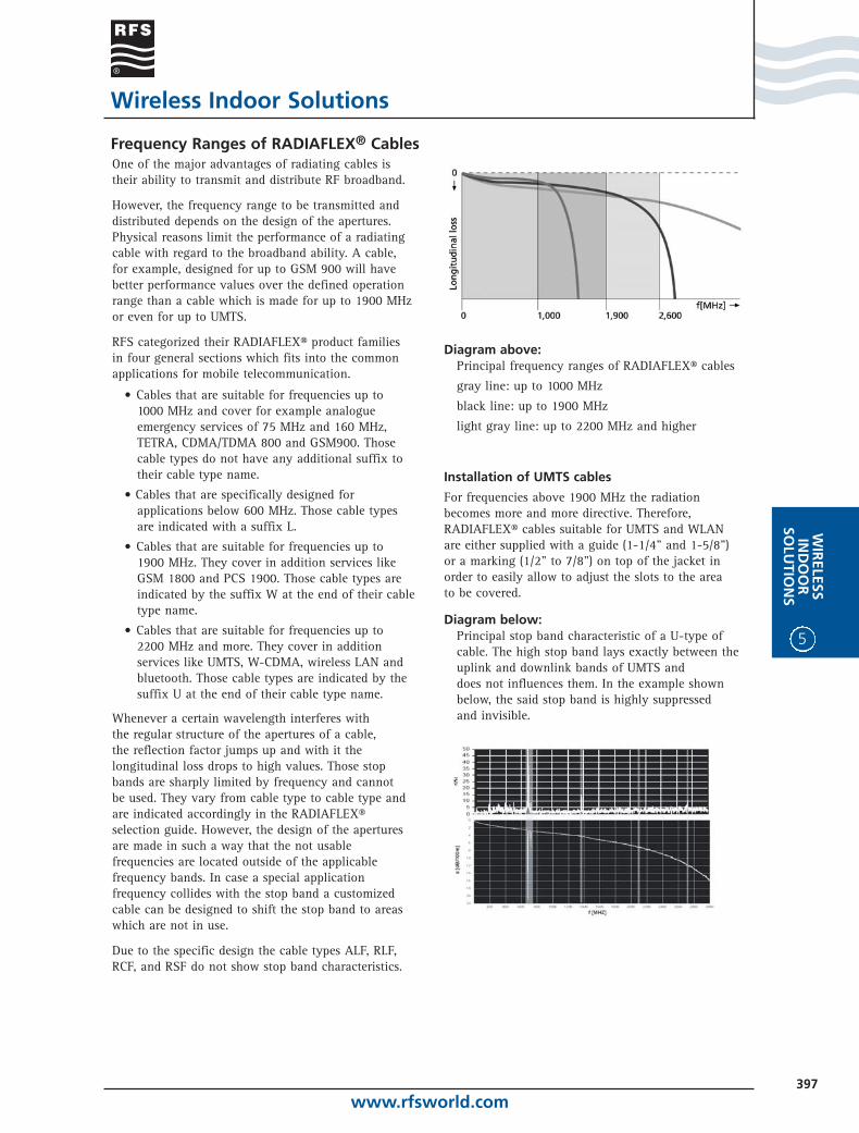
Frequency Ranges of RADIAFLEX® CablesOne of the major advantages of radiating cables istheir ability to transmit and distribute RF broadband.
However, the frequency range to be transmitted anddistributed depends on the design of the apertures.Physical reasons limit the performance of a radiatingcable with regard to the broadband ability. A cable,for example, designed for up to GSM 900 will havebetter performance values over the defined operationrange than a cable which is made for up to 1900 MHzor even for up to UMTS.
RFS categorized their RADIAFLEX® product families in four general sections which fits into the commonapplications for mobile telecommunication.
• Cables that are suitable for frequencies up to 1000 MHz and cover for example analogueemergency services of 75 MHz and 160 MHz, TETRA, CDMA/TDMA 800 and GSM900. Those cable types do not have any additional suffix to their cable type name.
• Cables that are specifically designed forapplications below 600 MHz. Those cable typesare indicated with a suffix L.
• Cables that are suitable for frequencies up to 1900 MHz. They cover in addition services like GSM 1800 and PCS 1900. Those cable types areindicated by the suffix W at the end of their cabletype name.
• Cables that are suitable for frequencies up to 2200 MHz and more. They cover in additionservices like UMTS, W-CDMA, wireless LAN andbluetooth. Those cable types are indicated by thesuffix U at the end of their cable type name.
Whenever a certain wavelength interferes with the regular structure of the apertures of a cable, the reflection factor jumps up and with it thelongitudinal loss drops to high values. Those stopbands are sharply limited by frequency and cannot be used. They vary from cable type to cable type andare indicated accordingly in the RADIAFLEX®selection guide. However, the design of the aperturesare made in such a way that the not usablefrequencies are located outside of the applicablefrequency bands. In case a special applicationfrequency collides with the stop band a customizedcable can be designed to shift the stop band to areaswhich are not in use.
Due to the specific design the cable types ALF, RLF,RCF, and RSF do not show stop band characteristics.
Diagram above: Principal frequency ranges of RADIAFLEX® cables
gray line: up to 1000 MHz
black line: up to 1900 MHz
light gray line: up to 2200 MHz and higher
Installation of UMTS cables
For frequencies above 1900 MHz the radiation becomes more and more directive. Therefore,RADIAFLEX® cables suitable for UMTS and WLAN are either supplied with a guide (1-1/4" and 1-5/8") or a marking (1/2" to 7/8") on top of the jacket in order to easily allow to adjust the slots to the area to be covered.
Diagram below: Principal stop band characteristic of a U-type ofcable. The high stop band lays exactly between theuplink and downlink bands of UMTS and does not influences them. In the example shownbelow, the said stop band is highly suppressed and invisible.
www.rfsworld.com398
5
WIR
ELES
SIN
DO
OR
SOLU
TIO
NS
Wireless Indoor Solutions
Coupling Loss Definition andMeasurement
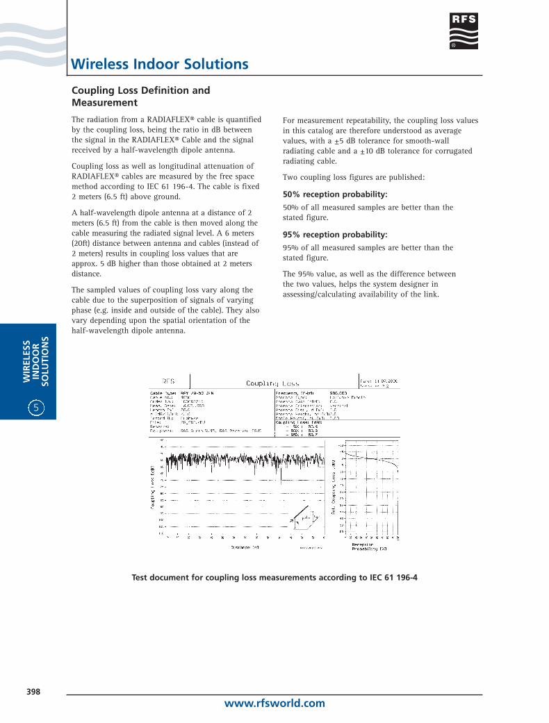
The radiation from a RADIAFLEX® cable is quantifiedby the coupling loss, being the ratio in dB between the signal in the RADIAFLEX® Cable and the signalreceived by a half-wavelength dipole antenna.
Coupling loss as well as longitudinal attenuation ofRADIAFLEX® cables are measured by the free spacemethod according to IEC 61 196-4. The cable is fixed 2 meters (6.5 ft) above ground.
A half-wavelength dipole antenna at a distance of 2meters (6.5 ft) from the cable is then moved along thecable measuring the radiated signal level. A 6 meters(20ft) distance between antenna and cables (instead of 2 meters) results in coupling loss values that areapprox. 5 dB higher than those obtained at 2 metersdistance.
The sampled values of coupling loss vary along thecable due to the superposition of signals of varyingphase (e.g. inside and outside of the cable). They alsovary depending upon the spatial orientation of the half-wavelength dipole antenna.
For measurement repeatability, the coupling loss valuesin this catalog are therefore understood as averagevalues, with a ±5 dB tolerance for smooth-wallradiating cable and a ±10 dB tolerance for corrugatedradiating cable.
Two coupling loss figures are published:
50% reception probability:
50% of all measured samples are better than the stated figure.
95% reception probability:
95% of all measured samples are better than the stated figure.
The 95% value, as well as the difference between the two values, helps the system designer inassessing/calculating availability of the link.
Test document for coupling loss measurements according to IEC 61 196-4
www.rfsworld.com399
WIR
ELESSIN
DO
OR
SOLU
TION
S
5
Wireless Indoor Solutions
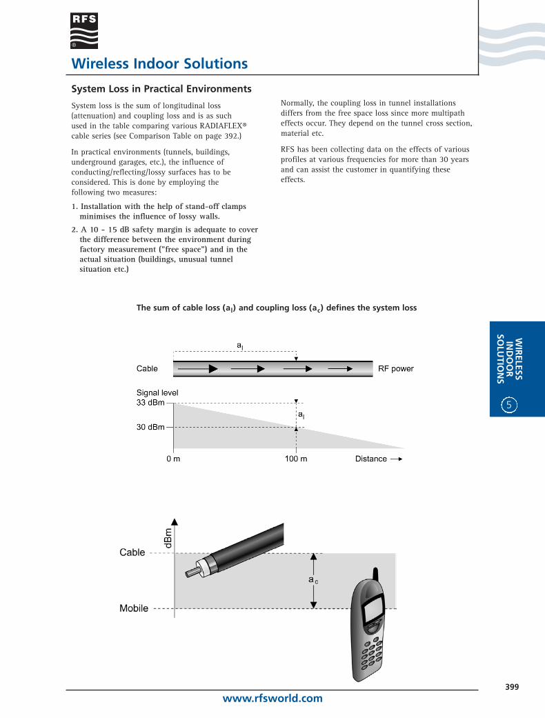
System Loss in Practical Environments
System loss is the sum of longitudinal loss (attenuation) and coupling loss and is as such used in the table comparing various RADIAFLEX® cable series (see Comparison Table on page 392.)
In practical environments (tunnels, buildings,underground garages, etc.), the influence ofconducting/reflecting/lossy surfaces has to beconsidered. This is done by employing the following two measures:
1. Installation with the help of stand-off clampsminimises the influence of lossy walls.
2. A 10 - 15 dB safety margin is adequate to coverthe difference between the environment duringfactory measurement ("free space") and in theactual situation (buildings, unusual tunnel situation etc.)
Normally, the coupling loss in tunnel installationsdiffers from the free space loss since more multipatheffects occur. They depend on the tunnel cross section,material etc.
RFS has been collecting data on the effects of variousprofiles at various frequencies for more than 30 yearsand can assist the customer in quantifying theseeffects.
The sum of cable loss (al) and coupling loss (ac) defines the system loss
www.rfsworld.com400
5
WIR
ELES
SIN
DO
OR
SOLU
TIO
NS
Distance
Wireless Indoor Solutions
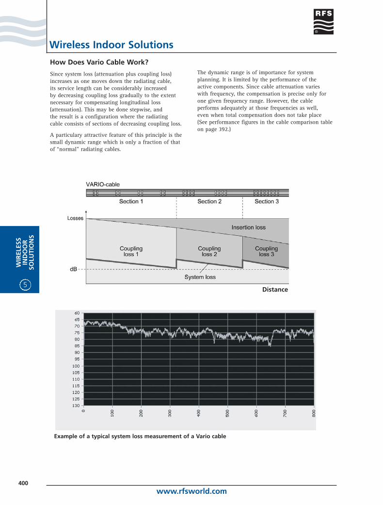
How Does Vario Cable Work?
Since system loss (attenuation plus coupling loss)increases as one moves down the radiating cable,its service length can be considerably increased by decreasing coupling loss gradually to the extentnecessary for compensating longitudinal loss(attenuation). This may be done stepwise, and the result is a configuration where the radiating cable consists of sections of decreasing coupling loss.
A particulary attractive feature of this principle is thesmall dynamic range which is only a fraction of that of “normal" radiating cables.
The dynamic range is of importance for systemplanning. It is limited by the performance of the active components. Since cable attenuation varies with frequency, the compensation is precise only forone given frequency range. However, the cable performs adequately at those frequencies as well, even when total compensation does not take place (See performance figures in the cable comparison tableon page 392.)
Example of a typical system loss measurement of a Vario cable
www.rfsworld.com401
WIR
ELESSIN
DO
OR
SOLU
TION
S
5
Wireless Indoor Solutions
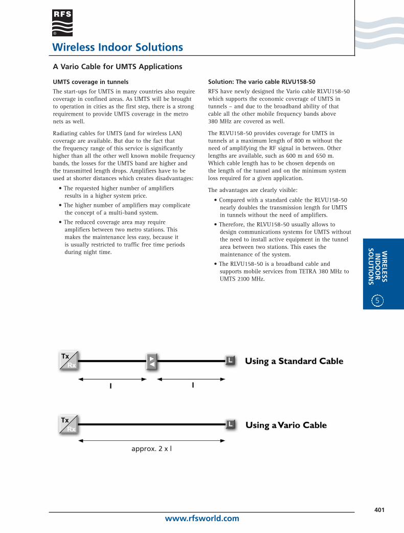
A Vario Cable for UMTS Applications
UMTS coverage in tunnels
The start-ups for UMTS in many countries also requirecoverage in confined areas. As UMTS will be broughtto operation in cities as the first step, there is a strongrequirement to provide UMTS coverage in the metronets as well.
Radiating cables for UMTS (and for wireless LAN)coverage are available. But due to the fact that the frequency range of this service is significantlyhigher than all the other well known mobile frequencybands, the losses for the UMTS band are higher andthe transmitted length drops. Amplifiers have to beused at shorter distances which creates disadvantages:
• The requested higher number of amplifiersresults in a higher system price.
• The higher number of amplifiers may complicatethe concept of a multi-band system.
• The reduced coverage area may requireamplifiers between two metro stations. Thismakes the maintenance less easy, because itis usually restricted to traffic free time periodsduring night time.
Solution: The vario cable RLVU158-50
RFS have newly designed the Vario cable RLVU158-50which supports the economic coverage of UMTS intunnels – and due to the broadband ability of that cable all the other mobile frequency bands above 380 MHz are covered as well.
The RLVU158-50 provides coverage for UMTS intunnels at a maximum length of 800 m without theneed of amplifying the RF signal in between. Otherlengths are available, such as 600 m and 650 m. Which cable length has to be chosen depends on the length of the tunnel and on the minimum systemloss required for a given application.
The advantages are clearly visible:
• Compared with a standard cable the RLVU158-50nearly doubles the transmission length for UMTS in tunnels without the need of amplifiers.
• Therefore, the RLVU158-50 usually allows todesign communications systems for UMTS withoutthe need to install active equipment in the tunnelarea between two stations. This eases themaintenance of the system.
• The RLVU158-50 is a broadband cable andsupports mobile services from TETRA 380 MHz toUMTS 2100 MHz.
approx. 2 x l
www.rfsworld.com402
5
WIR
ELES
SIN
DO
OR
SOLU
TIO
NS
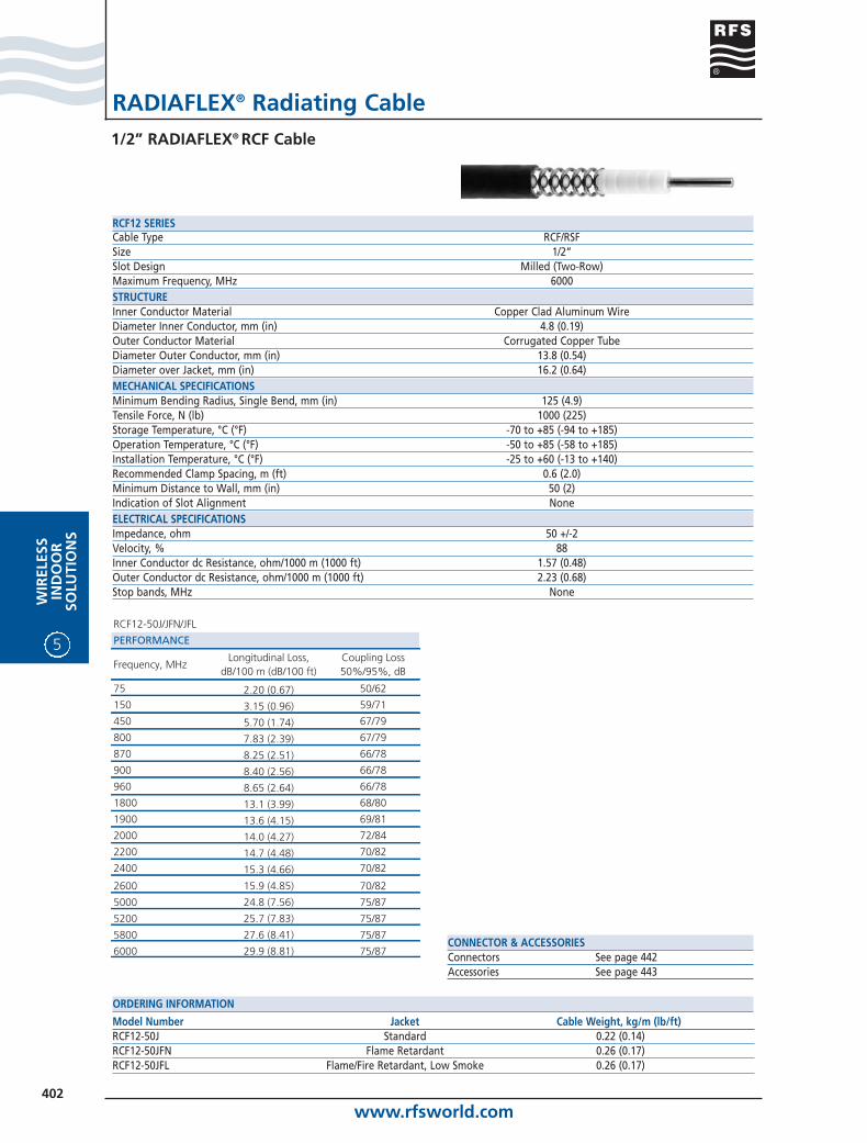
RADIAFLEX® Radiating Cable1/2” RADIAFLEX® RCF Cable
CONNECTOR & ACCESSORIESConnectors See page 442Accessories See page 443
Model Number Jacket Cable Weight, kg/m (lb/ft)RCF12-50J Standard 0.22 (0.14)RCF12-50JFN Flame Retardant 0.26 (0.17)RCF12-50JFL Flame/Fire Retardant, Low Smoke 0.26 (0.17)
ORDERING INFORMATION
Cable Type RCF/RSFSize 1/2”Slot Design Milled (Two-Row)Maximum Frequency, MHz 6000STRUCTUREInner Conductor Material Copper Clad Aluminum WireDiameter Inner Conductor, mm (in) 4.8 (0.19)Outer Conductor Material Corrugated Copper TubeDiameter Outer Conductor, mm (in) 13.8 (0.54)Diameter over Jacket, mm (in) 16.2 (0.64)MECHANICAL SPECIFICATIONSMinimum Bending Radius, Single Bend, mm (in) 125 (4.9)Tensile Force, N (lb) 1000 (225)Storage Temperature, °C (°F) -70 to +85 (-94 to +185)Operation Temperature, °C (°F) -50 to +85 (-58 to +185)Installation Temperature, °C (°F) -25 to +60 (-13 to +140)Recommended Clamp Spacing, m (ft) 0.6 (2.0)Minimum Distance to Wall, mm (in) 50 (2)Indication of Slot Alignment NoneELECTRICAL SPECIFICATIONSImpedance, ohm 50 +/-2Velocity, % 88Inner Conductor dc Resistance, ohm/1000 m (1000 ft) 1.57 (0.48)Outer Conductor dc Resistance, ohm/1000 m (1000 ft) 2.23 (0.68)Stop bands, MHz None
RCF12 SERIES
RCF12-50J/JFN/JFL
PERFORMANCE
Frequency, MHzLongitudinal Loss,
dB/100 m (dB/100 ft)Coupling Loss 50%/95%, dB
75 2.20 (0.67) 50/62
150 3.15 (0.96) 59/71
450 5.70 (1.74) 67/79
800 7.83 (2.39) 67/79
870 8.25 (2.51) 66/78
900 8.40 (2.56) 66/78
960 8.65 (2.64) 66/78
1800 13.1 (3.99) 68/80
1900 13.6 (4.15) 69/81
2000 14.0 (4.27) 72/84
2200 14.7 (4.48) 70/82
2400 15.3 (4.66) 70/82
2600 15.9 (4.85) 70/82
5000 24.8 (7.56) 75/87
5200 25.7 (7.83) 75/87
5800 27.6 (8.41) 75/87
6000 29.9 (8.81) 75/87
www.rfsworld.com403
WIR
ELESSIN
DO
OR
SOLU
TION
S
5
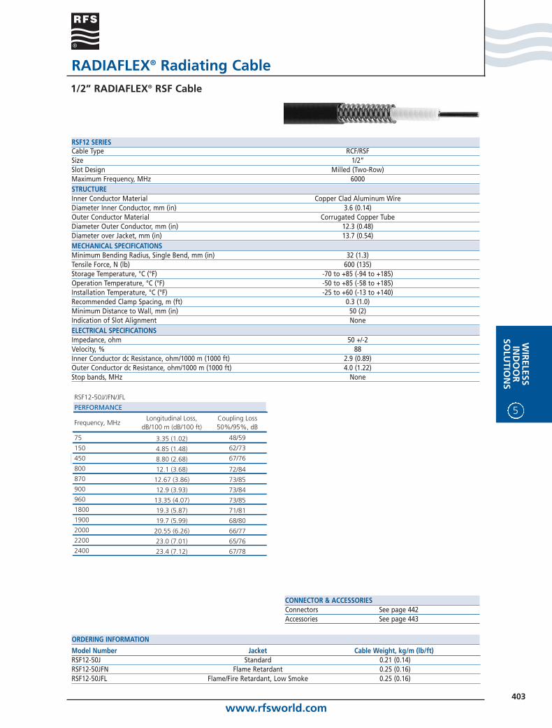
RADIAFLEX® Radiating Cable1/2” RADIAFLEX® RSF Cable
CONNECTOR & ACCESSORIESConnectors See page 442Accessories See page 443
Model Number Jacket Cable Weight, kg/m (lb/ft)RSF12-50J Standard 0.21 (0.14)RSF12-50JFN Flame Retardant 0.25 (0.16)RSF12-50JFL Flame/Fire Retardant, Low Smoke 0.25 (0.16)
ORDERING INFORMATION
Cable Type RCF/RSFSize 1/2”Slot Design Milled (Two-Row)Maximum Frequency, MHz 6000STRUCTUREInner Conductor Material Copper Clad Aluminum WireDiameter Inner Conductor, mm (in) 3.6 (0.14)Outer Conductor Material Corrugated Copper TubeDiameter Outer Conductor, mm (in) 12.3 (0.48)Diameter over Jacket, mm (in) 13.7 (0.54)MECHANICAL SPECIFICATIONSMinimum Bending Radius, Single Bend, mm (in) 32 (1.3)Tensile Force, N (lb) 600 (135)Storage Temperature, °C (°F) -70 to +85 (-94 to +185)Operation Temperature, °C (°F) -50 to +85 (-58 to +185)Installation Temperature, °C (°F) -25 to +60 (-13 to +140)Recommended Clamp Spacing, m (ft) 0.3 (1.0)Minimum Distance to Wall, mm (in) 50 (2)Indication of Slot Alignment NoneELECTRICAL SPECIFICATIONSImpedance, ohm 50 +/-2Velocity, % 88Inner Conductor dc Resistance, ohm/1000 m (1000 ft) 2.9 (0.89)Outer Conductor dc Resistance, ohm/1000 m (1000 ft) 4.0 (1.22)Stop bands, MHz None
RSF12 SERIES
RSF12-50J/JFN/JFL
PERFORMANCE
Frequency, MHzLongitudinal Loss,
dB/100 m (dB/100 ft)Coupling Loss 50%/95%, dB
75 3.35 (1.02) 48/59
150 4.85 (1.48) 62/73
450 8.80 (2.68) 67/76
800 12.1 (3.68) 72/84870 12.67 (3.86) 73/85900 12.9 (3.93) 73/84960 13.35 (4.07) 73/851800 19.3 (5.87) 71/811900 19.7 (5.99) 68/802000 20.55 (6.26) 66/772200 23.0 (7.01) 65/762400 23.4 (7.12) 67/78

www.rfsworld.com404
5
WIR
ELES
SIN
DO
OR
SOLU
TIO
NS
RADIAFLEX® Radiating Cable1/2” RADIAFLEX® RHCA Cable
CONNECTOR & ACCESSORIESConnectors See page 442Accessories See page 443
Model Number Jacket Cable Weight, kg/m (lb/ft)RHCA12-50JPL Plenum Rated 0.27 (0.18)
ORDERING INFORMATION
Cable Type RHCASize 1/2”Slot Design Milled (Two-Row)Maximum Frequency, MHz 6000STRUCTUREInner Conductor Material Copper Clad Aluminum WireDiameter Inner Conductor, mm (in) 4.8 (0.19)Outer Conductor Material Corrugated Copper TubeDiameter Outer Conductor, mm (in) 14.0 (0.55)Diameter over Jacket, mm (in) 15.5 (0.61)MECHANICAL SPECIFICATIONSMinimum Bending Radius, Single Bend, mm (in) 127 (5.0)Tensile Force, N (lb) 900 (203)Storage Temperature, °C (°F) -40 to +85 (-40 to +185)Operation Temperature, °C (°F) -40 to +85 (-40 to +185)Installation Temperature, °C (°F) -40 to +60 (-40 to +140)Recommended Clamp Spacing, m (ft) 0.6 (2.0)Minimum Distance to Wall, mm (in) 50 (2)Indication of Slot Alignment NoneELECTRICAL SPECIFICATIONSImpedance, ohm 50 +/-2Velocity, % 91Inner Conductor dc Resistance, ohm/1000 m (1000 ft) 1.48 (0.45)Outer Conductor dc Resistance, ohm/1000 m (1000 ft) 1.90 (0.58)Stop bands, MHz None
RHCA12 SERIES
RHCA12-50JPL
PERFORMANCE
Frequency, MHzLongitudinal Loss,
dB/100 m (dB/100 ft)Coupling Loss 50%/95%, dB
75 2.90 (0.83) 51/63
150 4.30 (1.31) 59/70
450 8.40 (2.56) 69/81
800 11.9 (3.63) 74/85
900 12.7 (3.87) 72/84
1800 20.1 (6.13) 70/81
1900 20.8 (6.34) 65/77
2200 22.8 (6.95) 65/77
2400 24.2 (7.38) 68/80
www.rfsworld.com405
WIR
ELESSIN
DO
OR
SOLU
TION
S
5
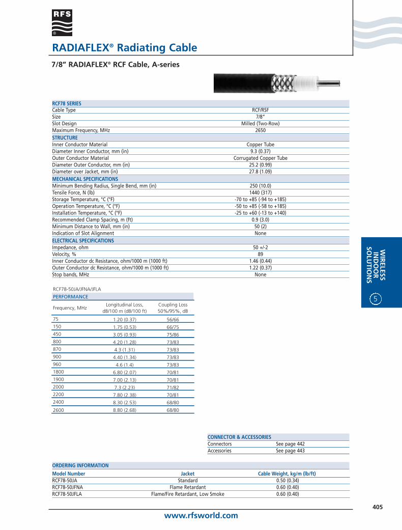
RADIAFLEX® Radiating Cable7/8” RADIAFLEX® RCF Cable, A-series
CONNECTOR & ACCESSORIESConnectors See page 442Accessories See page 443
Model Number Jacket Cable Weight, kg/m (lb/ft)RCF78-50JA Standard 0.50 (0.34)RCF78-50JFNA Flame Retardant 0.60 (0.40)RCF78-50JFLA Flame/Fire Retardant, Low Smoke 0.60 (0.40)
ORDERING INFORMATION
Cable Type RCF/RSFSize 7/8”Slot Design Milled (Two-Row)Maximum Frequency, MHz 2650STRUCTUREInner Conductor Material Copper TubeDiameter Inner Conductor, mm (in) 9.3 (0.37)Outer Conductor Material Corrugated Copper TubeDiameter Outer Conductor, mm (in) 25.2 (0.99)Diameter over Jacket, mm (in) 27.8 (1.09)MECHANICAL SPECIFICATIONSMinimum Bending Radius, Single Bend, mm (in) 250 (10.0)Tensile Force, N (lb) 1440 (317)Storage Temperature, °C (°F) -70 to +85 (-94 to +185)Operation Temperature, °C (°F) -50 to +85 (-58 to +185)Installation Temperature, °C (°F) -25 to +60 (-13 to +140)Recommended Clamp Spacing, m (ft) 0.9 (3.0)Minimum Distance to Wall, mm (in) 50 (2)Indication of Slot Alignment NoneELECTRICAL SPECIFICATIONSImpedance, ohm 50 +/-2Velocity, % 89Inner Conductor dc Resistance, ohm/1000 m (1000 ft) 1.46 (0.44)Outer Conductor dc Resistance, ohm/1000 m (1000 ft) 1.22 (0.37)Stop bands, MHz None
RCF78 SERIES
RCF78-50JA/JFNA/JFLA
PERFORMANCE
Frequency, MHzLongitudinal Loss,
dB/100 m (dB/100 ft)Coupling Loss 50%/95%, dB
75 1.20 (0.37) 56/66150 1.75 (0.53) 66/75450 3.05 (0.93) 75/86800 4.20 (1.28) 73/83870 4.3 (1.31) 73/83900 4.40 (1.34) 73/83960 4.6 (1.4) 73/831800 6.80 (2.07) 70/811900 7.00 (2.13) 70/812000 7.3 (2.23) 71/822200 7.80 (2.38) 70/812400 8.30 (2.53) 68/80
2600 8.80 (2.68) 68/80
www.rfsworld.com406
5
WIR
ELES
SIN
DO
OR
SOLU
TIO
NS
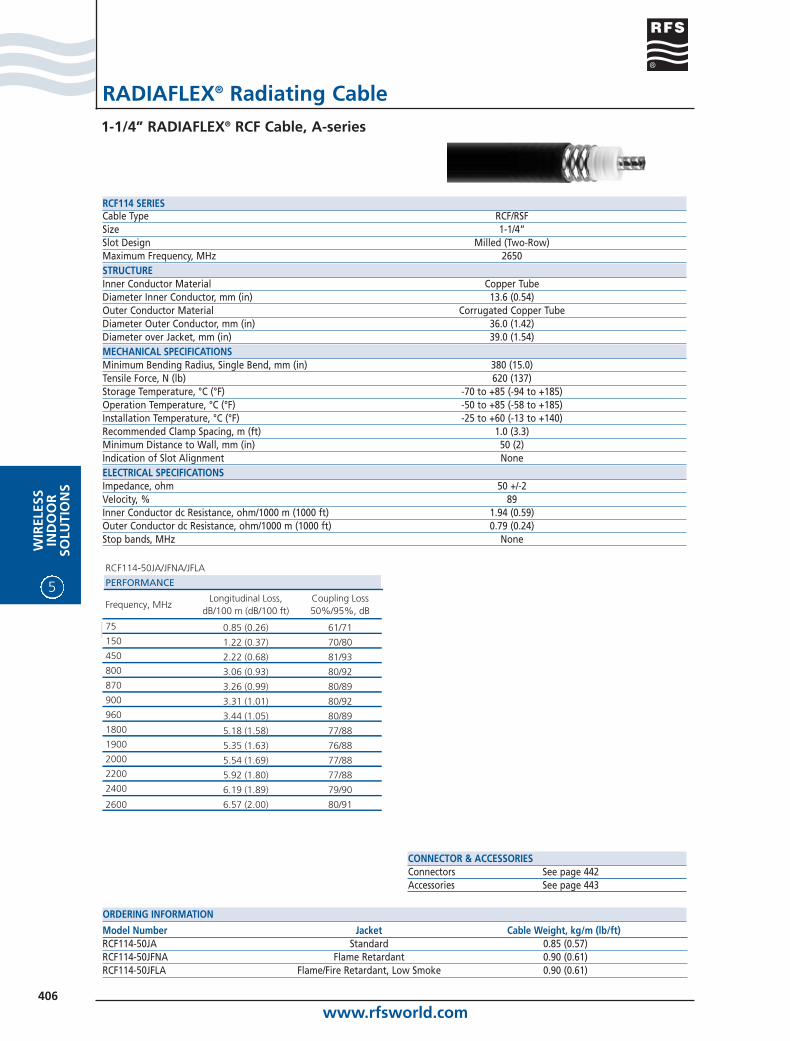
RADIAFLEX® Radiating Cable1-1/4” RADIAFLEX® RCF Cable, A-series
CONNECTOR & ACCESSORIESConnectors See page 442Accessories See page 443
Model Number Jacket Cable Weight, kg/m (lb/ft)RCF114-50JA Standard 0.85 (0.57)RCF114-50JFNA Flame Retardant 0.90 (0.61)RCF114-50JFLA Flame/Fire Retardant, Low Smoke 0.90 (0.61)
ORDERING INFORMATION
Cable Type RCF/RSFSize 1-1/4”Slot Design Milled (Two-Row)Maximum Frequency, MHz 2650STRUCTUREInner Conductor Material Copper TubeDiameter Inner Conductor, mm (in) 13.6 (0.54)Outer Conductor Material Corrugated Copper TubeDiameter Outer Conductor, mm (in) 36.0 (1.42)Diameter over Jacket, mm (in) 39.0 (1.54)MECHANICAL SPECIFICATIONSMinimum Bending Radius, Single Bend, mm (in) 380 (15.0)Tensile Force, N (lb) 620 (137)Storage Temperature, °C (°F) -70 to +85 (-94 to +185)Operation Temperature, °C (°F) -50 to +85 (-58 to +185)Installation Temperature, °C (°F) -25 to +60 (-13 to +140)Recommended Clamp Spacing, m (ft) 1.0 (3.3)Minimum Distance to Wall, mm (in) 50 (2)Indication of Slot Alignment NoneELECTRICAL SPECIFICATIONSImpedance, ohm 50 +/-2Velocity, % 89Inner Conductor dc Resistance, ohm/1000 m (1000 ft) 1.94 (0.59)Outer Conductor dc Resistance, ohm/1000 m (1000 ft) 0.79 (0.24)Stop bands, MHz None
RCF114 SERIES
RCF114-50JA/JFNA/JFLA
PERFORMANCE
Frequency, MHzLongitudinal Loss,
dB/100 m (dB/100 ft)Coupling Loss 50%/95%, dB
75 0.85 (0.26) 61/71150 1.22 (0.37) 70/80450 2.22 (0.68) 81/93800 3.06 (0.93) 80/92870 3.26 (0.99) 80/89900 3.31 (1.01) 80/92960 3.44 (1.05) 80/891800 5.18 (1.58) 77/881900 5.35 (1.63) 76/882000 5.54 (1.69) 77/882200 5.92 (1.80) 77/882400 6.19 (1.89) 79/90
2600 6.57 (2.00) 80/91

www.rfsworld.com407
WIR
ELESSIN
DO
OR
SOLU
TION
S
5
RADIAFLEX® Radiating Cable1-5/8” RADIAFLEX® RCF Cable, A-series
CONNECTOR & ACCESSORIESConnectors See page 442Accessories See page 443
Model Number Jacket Cable Weight, kg/m (lb/ft)RCF158-50JA Standard 1.20 (0.81)RCF158-50JFNA Flame Retardant 1.30 (0.87)RCF158-50JFLA Flame/Fire Retardant, Low Smoke 1.30 (0.87)
ORDERING INFORMATION
Cable Type RCF/RSFSize 1-5/8”Slot Design Milled (Two-Row)Maximum Frequency, MHz 2650STRUCTUREInner Conductor Material Corrugated Copper TubeDiameter Inner Conductor, mm (in) 17.6 (0.69)Outer Conductor Material Corrugated Copper TubeDiameter Outer Conductor, mm (in) 46.5 (1.83)Diameter over Jacket, mm (in) 50.3 (1.98)MECHANICAL SPECIFICATIONSMinimum Bending Radius, Single Bend, mm (in) 500 (19.7)Tensile Force, N (lb) 1080 (238)Storage Temperature, °C (°F) -70 to +85 (-94 to +185)Operation Temperature, °C (°F) -50 to +85 (-58 to +185)Installation Temperature, °C (°F) -25 to +60 (-13 to +140)Recommended Clamp Spacing, m (ft) 1.2 (4.0)Minimum Distance to Wall, mm (in) 50 (2)Indication of Slot Alignment NoneELECTRICAL SPECIFICATIONSImpedance, ohm 50 +/-2Velocity, % 89Inner Conductor dc Resistance, ohm/1000 m (1000 ft) 1.26 (0.38)Outer Conductor dc Resistance, ohm/1000 m (1000 ft) 0.55 (0.17)Stop bands, MHz None
RCF158 SERIES
RCF158-50JA/JFNA/JFLA
PERFORMANCE
Frequency, MHzLongitudinal Loss,
dB/100 m (dB/100 ft)Coupling Loss 50%/95%, dB
75 0.59 (0.18) 62/74150 0.86 (0.26) 70/80450 1.60 (0.49) 83/93800 2.25 (0.69) 84/94870 2.37 (0.72) 82/92900 2.42 (0.74) 82/92960 2.51 (0.77) 82/921800 3.80 (1.16) 81/911900 3.94 (1.20) 80/902000 4.08 (1.24) 80/902200 4.36 (1.33) 80/902400 4.65 (1.42) 80/90
2600 4.92 (1.50) 80/90
www.rfsworld.com408
5
WIR
ELES
SIN
DO
OR
SOLU
TIO
NS
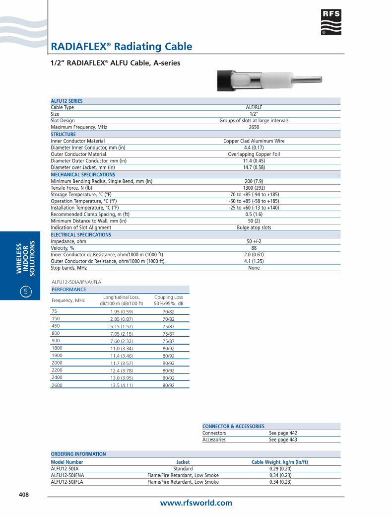
RADIAFLEX® Radiating Cable1/2” RADIAFLEX® ALFU Cable, A-series
CONNECTOR & ACCESSORIESConnectors See page 442Accessories See page 443
Model Number Jacket Cable Weight, kg/m (lb/ft)ALFU12-50JA Standard 0.29 (0.20)ALFU12-50JFNA Flame/Fire Retardant, Low Smoke 0.34 (0.23)ALFU12-50JFLA Flame/Fire Retardant, Low Smoke 0.34 (0.23)
ORDERING INFORMATION
Cable Type ALF/RLFSize 1/2”Slot Design Groups of slots at large intervalsMaximum Frequency, MHz 2650STRUCTUREInner Conductor Material Copper Clad Aluminum WireDiameter Inner Conductor, mm (in) 4.4 (0.17)Outer Conductor Material Overlapping Copper FoilDiameter Outer Conductor, mm (in) 11.4 (0.45)Diameter over Jacket, mm (in) 14.7 (0.58)MECHANICAL SPECIFICATIONSMinimum Bending Radius, Single Bend, mm (in) 200 (7.9)Tensile Force, N (lb) 1300 (292)Storage Temperature, °C (°F) -70 to +85 (-94 to +185)Operation Temperature, °C (°F) -50 to +85 (-58 to +185)Installation Temperature, °C (°F) -25 to +60 (-13 to +140)Recommended Clamp Spacing, m (ft) 0.5 (1.6)Minimum Distance to Wall, mm (in) 50 (2)Indication of Slot Alignment Bulge atop slotsELECTRICAL SPECIFICATIONSImpedance, ohm 50 +/-2Velocity, % 88Inner Conductor dc Resistance, ohm/1000 m (1000 ft) 2.0 (0.61)Outer Conductor dc Resistance, ohm/1000 m (1000 ft) 4.1 (1.25)Stop bands, MHz None
ALFU12 SERIES
ALFU12-50JA/JFNA/JFLA
PERFORMANCE
Frequency, MHzLongitudinal Loss,
dB/100 m (dB/100 ft)Coupling Loss 50%/95%, dB
75 1.95 (0.59) 70/82150 2.85 (0.87) 70/82450 5.15 (1.57) 75/87800 7.05 (2.15) 75/87900 7.60 (2.32) 75/871800 11.0 (3.34) 80/921900 11.4 (3.46) 80/922000 11.7 (3.57) 80/922200 12.4 (3.78) 80/922400 13.0 (3.95) 80/92
2600 13.5 (4.11) 80/92
www.rfsworld.com409
WIR
ELESSIN
DO
OR
SOLU
TION
S
5
RADIAFLEX® Radiating Cable7/8” RADIAFLEX® RLF Cable, A-series
CONNECTOR & ACCESSORIESConnectors See page 442Accessories See page 443
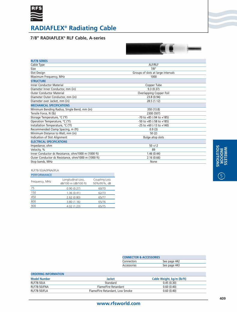
Model Number Jacket Cable Weight, kg/m (lb/ft)RLF78-50JA Standard 0.45 (0.30)RLF78-50JFNA Flame/Fire Retardant 0.60 (0.40)RLF78-50JFLA Flame/Fire Retardant, Low Smoke 0.60 (0.40)
ORDERING INFORMATION
Cable Type ALF/RLFSize 7/8”Slot Design Groups of slots at large intervalsMaximum Frequency, MHz 1000STRUCTUREInner Conductor Material Copper TubeDiameter Inner Conductor, mm (in) 9.3 (0.37)Outer Conductor Material Overlapping Copper FoilDiameter Outer Conductor, mm (in) 23.8 (0.94)Diameter over Jacket, mm (in) 28.5 (1.12)MECHANICAL SPECIFICATIONSMinimum Bending Radius, Single Bend, mm (in) 350 (13.8)Tensile Force, N (lb) 2300 (507)Storage Temperature, °C (°F) -70 to +85 (-94 to +185)Operation Temperature, °C (°F) -50 to +85 (-58 to +185)Installation Temperature, °C (°F) -25 to +60 (-13 to +140)Recommended Clamp Spacing, m (ft) 0.9 (3)Minimum Distance to Wall, mm (in) 50 (2)Indication of Slot Alignment Bulge atop slotsELECTRICAL SPECIFICATIONSImpedance, ohm 50 +/-2Velocity, % 89Inner Conductor dc Resistance, ohm/1000 m (1000 ft) 1.46 (0.44)Outer Conductor dc Resistance, ohm/1000 m (1000 ft) 2.16 (0.66)Stop bands, MHz None
RLF78 SERIES
RLF78-50JA/JFNA/JFLA
PERFORMANCE
Frequency, MHzLongitudinal Loss,
dB/100 m (dB/100 ft)Coupling Loss 50%/95%, dB
75 0.90 (0.27) 60/70150 1.36 (0.41) 62/73450 2.62 (0.80) 65/77800 3.80 (1.16) 65/76900 4.02 (1.23) 65/75

www.rfsworld.com410
5
WIR
ELES
SIN
DO
OR
SOLU
TIO
NS
RADIAFLEX® Radiating Cable7/8” RADIAFLEX® RLFW Cable, A-series
CONNECTOR & ACCESSORIESConnectors See page 442Accessories See page 443
Model Number Jacket Cable Weight, kg/m (lb/ft)RLFW78-50JA Standard 0.45 (0.30)RLFW78-50JFNA Flame/Fire Retardant 0.60 (0.40)RLFW78-50JFLA Flame/Fire Retardant, Low Smoke 0.60 (0.40)
ORDERING INFORMATION
Cable Type ALF/RLFSize 7/8”Slot Design Groups of slots at large intervalsMaximum Frequency, MHz 2000STRUCTUREInner Conductor Material Copper TubeDiameter Inner Conductor, mm (in) 9.3 (0.37)Outer Conductor Material Overlapping Copper FoilDiameter Outer Conductor, mm (in) 23.8 (0.94)Diameter over Jacket, mm (in) 28.5 (1.12)MECHANICAL SPECIFICATIONSMinimum Bending Radius, Single Bend, mm (in) 350 (13.8)Tensile Force, N (lb) 2300 (507)Storage Temperature, °C (°F) -70 to +85 (-94 to +185)Operation Temperature, °C (°F) -50 to +85 (-58 to +185)Installation Temperature, °C (°F) -25 to +60 (-13 to +140)Recommended Clamp Spacing, m (ft) 0.9 (3)Minimum Distance to Wall, mm (in) 50 (2)Indication of Slot Alignment Bulge atop slotsELECTRICAL SPECIFICATIONSImpedance, ohm 50 +/-2Velocity, % 89Inner Conductor dc Resistance, ohm/1000 m (1000 ft) 1.46 (0.44)Outer Conductor dc Resistance, ohm/1000 m (1000 ft) 2.16 (0.66)Stop bands, MHz None
RLFW78 SERIES
RLFW78-50JA/JFNA/JFLA
PERFORMANCE
Frequency, MHzLongitudinal Loss,
dB/100 m (dB/100 ft)Coupling Loss 50%/95%, dB
75 1.03 (0.31) 70/82150 1.49 (0.45) 70/81450 2.68 (0.82) 73/84800 3.90 (1.19) 73/84900 4.21 (1.28) 71/821800 7.90 (2.41) 68/801900 8.71 (2.66) 68/80

www.rfsworld.com411
WIR
ELESSIN
DO
OR
SOLU
TION
S
5
RADIAFLEX® Radiating Cable7/8” RADIAFLEX® RLFU Cable, A-series
CONNECTOR & ACCESSORIESConnectors See page 442Accessories See page 443
Model Number Jacket Cable Weight, kg/m (lb/ft)RLFU78-50JA Standard 0.45 (0.30)RLFU78-50JFNA Flame/Fire Retardant 0.60 (0.40)RLFU78-50JFLA Flame/Fire Retardant, Low Smoke 0.60 (0.40)
ORDERING INFORMATION
Cable Type ALF/RLFSize 7/8”Slot Design Groups of slots at large intervalsMaximum Frequency, MHz 2400STRUCTUREInner Conductor Material Copper TubeDiameter Inner Conductor, mm (in) 9.3 (0.37)Outer Conductor Material Overlapping Copper FoilDiameter Outer Conductor, mm (in) 23.8 (0.94)Diameter over Jacket, mm (in) 28.5 (1.12)MECHANICAL SPECIFICATIONSMinimum Bending Radius, Single Bend, mm (in) 350 (13.8)Tensile Force, N (lb) 2300 (507)Storage Temperature, °C (°F) -70 to +85 (-94 to +185)Operation Temperature, °C (°F) -50 to +85 (-58 to +185)Installation Temperature, °C (°F) -25 to +60 (-13 to +140)Recommended Clamp Spacing, m (ft) 0.9 (3)Minimum Distance to Wall, mm (in) 50 (2)Indication of Slot Alignment Bulge atop slotsELECTRICAL SPECIFICATIONSImpedance, ohm 50 +/-2Velocity, % 89Inner Conductor dc Resistance, ohm/1000 m (1000 ft) 1.46 (0.44)Outer Conductor dc Resistance, ohm/1000 m (1000 ft) 2.16 (0.66)Stop bands, MHz None
RLFU78 SERIES
RLFU78-50JA/JFNA/JFLA
PERFORMANCE
Frequency, MHzLongitudinal Loss,
dB/100 m (dB/100 ft)Coupling Loss 50%/95%, dB
75 1.02 (0.31) 63/73150 1.48 (0.45) 62/75450 2.76 (0.84) 66/78800 3.93 (1.20) 67/77870 4.10 (1.25) 62/74900 4.29 (1.13) 64/74960 4.37 (1.33) 66/771800 8.07 (2.46) 58/701900 8.81 (2.69) 59/702000 9.28 (2.83) 59/702200 10.72 (3.27) 58/692400 12.52 (3.82) 60/71

www.rfsworld.com412
5
WIR
ELES
SIN
DO
OR
SOLU
TIO
NS
RADIAFLEX® Radiating Cable1-1/4” RADIAFLEX® RLF Cable, A-series
CONNECTOR & ACCESSORIESConnectors See page 442Accessories See page 443
Model Number Jacket Cable Weight, kg/m (lb/ft)RLF114-50JA Standard 0.66 (0.44)RLF114-50JFNA Flame/Fire Retardant 0.90 (0.60)RLF114-50JFLA Flame/Fire Retardant, Low Smoke 0.90 (0.60)
ORDERING INFORMATION
Cable Type ALF/RLFSize 1-1/4”Slot Design Groups of slots at large intervalsMaximum Frequency, MHz 1000STRUCTUREInner Conductor Material Copper TubeDiameter Inner Conductor, mm (in) 13.1 (0.52)Outer Conductor Material Overlapping Copper FoilDiameter Outer Conductor, mm (in) 34.0 (1.34)Diameter over Jacket, mm (in) 38.1 (1.50)MECHANICAL SPECIFICATIONSMinimum Bending Radius, Single Bend, mm (in) 500 (20.0)Tensile Force, N (lb) 2000 (440)Storage Temperature, °C (°F) -70 to +85 (-94 to +185)Operation Temperature, °C (°F) -50 to +85 (-58 to +185)Installation Temperature, °C (°F) -25 to +60 (-13 to +140)Recommended Clamp Spacing, m (ft) 1.3 (4.25)Minimum Distance to Wall, mm (in) 50 (2)Indication of Slot Alignment Bulge atop slotsELECTRICAL SPECIFICATIONSImpedance, ohm 50 +/-2Velocity, % 89Inner Conductor dc Resistance, ohm/1000 m (1000 ft) 0.80 (0.24)Outer Conductor dc Resistance, ohm/1000 m (1000 ft) 1.75 (0.53)Stop bands, MHz None
RLF114 SERIES
RLF114-50JA/JFNA/JFLA
PERFORMANCE
Frequency, MHzLongitudinal Loss,
dB/100 m (dB/100 ft)Coupling Loss 50%/95%, dB
75 0.74 (0.23) 60/70150 1.04 (0.32) 62/73450 2.07 (0.63) 65/77800 3.28 (1.00) 65/75900 3.62 (1.10) 65/75

www.rfsworld.com413
WIR
ELESSIN
DO
OR
SOLU
TION
S
5
RADIAFLEX® Radiating Cable1-1/4” RADIAFLEX® RLFW Cable, A-series
CONNECTOR & ACCESSORIESConnectors See page 442Accessories See page 443
Model Number Jacket Cable Weight, kg/m (lb/ft)RLFW114-50JA Standard 0.66 (0.44)RLFW114-50JFNA Flame/Fire Retardant 0.90 (0.60)RLFW114-50JFLA Flame/Fire Retardant, Low Smoke 0.90 (0.60)
ORDERING INFORMATION
Cable Type ALF/RLFSize 1-1/4”Slot Design Groups of slots at large intervalsMaximum Frequency, MHz 2000STRUCTUREInner Conductor Material Copper TubeDiameter Inner Conductor, mm (in) 13.1 (0.52)Outer Conductor Material Overlapping Copper FoilDiameter Outer Conductor, mm (in) 34.0 (1.34)Diameter over Jacket, mm (in) 38.1 (1.50)MECHANICAL SPECIFICATIONSMinimum Bending Radius, Single Bend, mm (in) 500 (20.0)Tensile Force, N (lb) 2000 (440)Storage Temperature, °C (°F) -70 to +85 (-94 to +185)Operation Temperature, °C (°F) -50 to +85 (-58 to +185)Installation Temperature, °C (°F) -25 to +60 (-13 to +140)Recommended Clamp Spacing, m (ft) 1.3 (4.25)Minimum Distance to Wall, mm (in) 50 (2)Indication of Slot Alignment Bulge atop slotsELECTRICAL SPECIFICATIONSImpedance, ohm 50 +/-2Velocity, % 89Inner Conductor dc Resistance, ohm/1000 m (1000 ft) 0.80 (0.24)Outer Conductor dc Resistance, ohm/1000 m (1000 ft) 1.75 (0.53)Stop bands, MHz None
RLFW114 SERIES
RLFW114-50JA/JFNA/JFLA
PERFORMANCE
Frequency, MHzLongitudinal Loss,
dB/100 m (dB/100 ft)Coupling Loss 50%/95%, dB
75 0.76 (0.23) 71/83150 1.10 (0.33) 70/82450 1.97 (0.60) 73/85800 2.97 (0.91) 72/84900 3.05 (0.93) 70/821800 6.56 (2.00) 67/791900 7.62 (2.32) 66/78

www.rfsworld.com414
5
WIR
ELES
SIN
DO
OR
SOLU
TIO
NS
RADIAFLEX® Radiating Cable1-1/4” RADIAFLEX® RLFU Cable, A-series
CONNECTOR & ACCESSORIESConnectors See page 442Accessories See page 443
Model Number Jacket Cable Weight, kg/m (lb/ft)RLFU114-50JA Standard 0.66 (0.44)RLFU114-50JFNA Flame/Fire Retardant 0.90 (0.60)RLFU114-50JFLA Flame/Fire Retardant, Low Smoke 0.90 (0.60)
ORDERING INFORMATION
Cable Type ALF/RLFSize 1-1/4”Slot Design Groups of slots at large intervalsMaximum Frequency, MHz 2400STRUCTUREInner Conductor Material Copper TubeDiameter Inner Conductor, mm (in) 13.1 (0.52)Outer Conductor Material Overlapping Copper FoilDiameter Outer Conductor, mm (in) 34.0 (1.34)Diameter over Jacket, mm (in) 38.1 (1.50)MECHANICAL SPECIFICATIONSMinimum Bending Radius, Single Bend, mm (in) 500 (20.0)Tensile Force, N (lb) 2000 (440)Storage Temperature, °C (°F) -70 to +85 (-94 to +185)Operation Temperature, °C (°F) -50 to +85 (-58 to +185)Installation Temperature, °C (°F) -25 to +60 (-13 to +140)Recommended Clamp Spacing, m (ft) 1.3 (4.25)Minimum Distance to Wall, mm (in) 50 (2)Indication of Slot Alignment Bulge atop slotsELECTRICAL SPECIFICATIONSImpedance, ohm 50 +/-2Velocity, % 89Inner Conductor dc Resistance, ohm/1000 m (1000 ft) 0.80 (0.24)Outer Conductor dc Resistance, ohm/1000 m (1000 ft) 1.75 (0.53)Stop bands, MHz None
RLFU114 SERIES
RLFU114-50JA/JFNA/JFLA
PERFORMANCE
Frequency, MHzLongitudinal Loss,
dB/100 m (dB/100 ft)Coupling Loss 50%/95%, dB
75 0.74 (0.23) 67/80150 1.07 (0.33) 66/76450 1.96 (0.60) 67/76800 2.95 (0.90) 66/77870 3.02 (0.92) 65/77900 3.13 (0.95) 64/75960 3.44 (1.05) 64/751800 6.01 (1.83) 60/711900 6.53 (1.99) 61/722000 7.11 (2.17) 60/722200 8.07 (2.46) 59/692400 9.25 (2.82) 60/71

www.rfsworld.com415
WIR
ELESSIN
DO
OR
SOLU
TION
S
5
RADIAFLEX® Radiating Cable1-5/8” RADIAFLEX® RLF Cable, A-series
CONNECTOR & ACCESSORIESConnectors See page 442Accessories See page 443
Model Number Jacket Cable Weight, kg/m (lb/ft)RLF158-50JA Standard 0.80 (0.54)RLF158-50JFNA Flame/Fire Retardant 1.10 (0.74)RLF158-50JFLA Flame/Fire Retardant, Low Smoke 1.10 (0.74)
ORDERING INFORMATION
Cable Type ALF/RLFSize 1-5/8”Slot Design Groups of slots at large intervalsMaximum Frequency, MHz 1000STRUCTUREInner Conductor Material Corrugated Copper TubeDiameter Inner Conductor, mm (in) 17.6 (0.69)Outer Conductor Material Overlapping Copper FoilDiameter Outer Conductor, mm (in) 44.2 (1.74)Diameter over Jacket, mm (in) 48.2 (1.90)MECHANICAL SPECIFICATIONSMinimum Bending Radius, Single Bend, mm (in) 700 (28.0)Tensile Force, N (lb) 1200 (270)Storage Temperature, °C (°F) -70 to +85 (-94 to +185)Operation Temperature, °C (°F) -50 to +85 (-58 to +185)Installation Temperature, °C (°F) -25 to +60 (-13 to +140)Recommended Clamp Spacing, m (ft) 1.5 (5)Minimum Distance to Wall, mm (in) 50 (2)Indication of Slot Alignment Bulge atop slotsELECTRICAL SPECIFICATIONSImpedance, ohm 50 +/-2Velocity, % 89Inner Conductor dc Resistance, ohm/1000 m (1000 ft) 1.30 (0.40)Outer Conductor dc Resistance, ohm/1000 m (1000 ft) 1.30 (0.40)Stop bands, MHz None
RLF158 SERIES
RLF158-50JA/JFNA/JFLA
PERFORMANCE
Frequency, MHzLongitudinal Loss,
dB/100 m (dB/100 ft)Coupling Loss 50%/95%, dB
75 0.55 (0.17) 67/78150 0.78 (0.24) 66/77450 1.54 (0.47) 66/77800 2.21 (0.67) 66/77870 2.52 (0.77) 65/76900 2.38 (0.73) 65/76960 2.67 (0.81) 65/76

www.rfsworld.com416
5
WIR
ELES
SIN
DO
OR
SOLU
TIO
NS
RADIAFLEX® Radiating Cable1-5/8” RADIAFLEX® RLFW Cable, A-series
CONNECTOR & ACCESSORIESConnectors See page 442Accessories See page 443
Model Number Jacket Cable Weight, kg/m (lb/ft)RLFW158-50JA Standard 0:80 (0.54)RLFW158-50JFNA Flame/Fire Retardant 1.10 (0:74)RLFW158-50JFLA Flame/Fire Retardant, Low Smoke 1.10 (0:74)
ORDERING INFORMATION
Cable Type ALF/RLFSize 1-5/8”Slot Design Groups of slots at large intervalsMaximum Frequency, MHz 2000STRUCTUREInner Conductor Material Corrugated Copper TubeDiameter Inner Conductor, mm (in) 17.6 (0.69)Outer Conductor Material Overlapping Copper FoilDiameter Outer Conductor, mm (in) 44:2 (1.74)Diameter over Jacket, mm (in) 48.2 (1.90)MECHANICAL SPECIFICATIONSMinimum Bending Radius, Single Bend, mm (in) 700 (28.0)Tensile Force, N (lb) 1200 (270)Storage Temperature, °C (°F) -70 to +85 (-94 to +185)Operation Temperature, °C (°F) -50 to +85 (-58 to +185)Installation Temperature, °C (°F) -25 to +60 (-13 to +140)Recommended Clamp Spacing, m (ft) 1.5 (5)Minimum Distance to Wall, mm (in) 50 (2)Indication of Slot Alignment Bulge atop slotsELECTRICAL SPECIFICATIONSImpedance, ohm 50 +/-2Velocity, % 89Inner Conductor dc Resistance, ohm/1000 m (1000 ft) 1.30 (0.40)Outer Conductor dc Resistance, ohm/1000 m (1000 ft) 1.30 (0.40)Stop bands, MHz None
RLFW158 SERIES
RLFW158-50JA/JFNA/JFLA
PERFORMANCE
Frequency, MHzLongitudinal Loss,
dB/100 m (dB/100 ft)Coupling Loss 50%/95%, dB
75 0.57 (0.17) 68/79150 0.82 (0.25) 73/84450 1.46 (0.45) 75/86800 2.03 (0.62) 72/84900 2.25 (0.68) 70/811800 4.97 (1.51) 64/751900 5.85 (1.78) 63/74

www.rfsworld.com417
WIR
ELESSIN
DO
OR
SOLU
TION
S
5
RADIAFLEX® Radiating Cable1-5/8” RADIAFLEX® RLFU Cable, A-series
CONNECTOR & ACCESSORIESConnectors See page 442Accessories See page 443
Model Number Jacket Cable Weight, kg/m (lb/ft)RLFU158-50JA Standard 0:80 (0.54)RLFU158-50JFNA Flame/Fire Retardant 1.10 (0:74)RLFU158-50JFLA Flame/Fire Retardant, Low Smoke 1.10 (0:74)
ORDERING INFORMATION
Cable Type ALF/RLFSize 1-5/8”Slot Design Groups of slots at large intervalsMaximum Frequency, MHz 2400STRUCTUREInner Conductor Material Corrugated Copper TubeDiameter Inner Conductor, mm (in) 17.6 (0.69)Outer Conductor Material Overlapping Copper FoilDiameter Outer Conductor, mm (in) 44:2 (1.74)Diameter over Jacket, mm (in) 48.2 (1.90)MECHANICAL SPECIFICATIONSMinimum Bending Radius, Single Bend, mm (in) 700 (28.0)Tensile Force, N (lb) 1200 (270)Storage Temperature, °C (°F) -70 to +85 (-94 to +185)Operation Temperature, °C (°F) -50 to +85 (-58 to +185)Installation Temperature, °C (°F) -25 to +60 (-13 to +140)Recommended Clamp Spacing, m (ft) 1.5 (5)Minimum Distance to Wall, mm (in) 50 (2)Indication of Slot Alignment Bulge atop slotsELECTRICAL SPECIFICATIONSImpedance, ohm 50 +/-2Velocity, % 89Inner Conductor dc Resistance, ohm/1000 m (1000 ft) 1.30 (0.40)Outer Conductor dc Resistance, ohm/1000 m (1000 ft) 1.30 (0.40)Stop bands, MHz None
RLFU158 SERIES
RLFU158-50JA/JFNA/JFLA
PERFORMANCE
Frequency, MHzLongitudinal Loss,
dB/100 m (dB/100 ft)Coupling Loss 50%/95%, dB
75 0.56 (0.17) 67/78150 0.81 (0.25) 67/78450 1.53 (0.47) 67/77800 2.26 (0.69) 67/77870 2.47 (0.75) 65/75900 2.51 (0.77) 65/75960 2.61 (0.80) 65/751800 5.52 (1.68) 61/711900 5.95 (1.81) 61/712000 6.45 (1.97) 61/712200 7.65 (2.33) 61/712400 9.50 (2.90) 61/71
www.rfsworld.com418
5
WIR
ELES
SIN
DO
OR
SOLU
TIO
NS
RADIAFLEX® Radiating Cable1/2” RADIAFLEX® RLKW Cable, A-series
CONNECTOR & ACCESSORIESConnectors See page 442Accessories See page 443
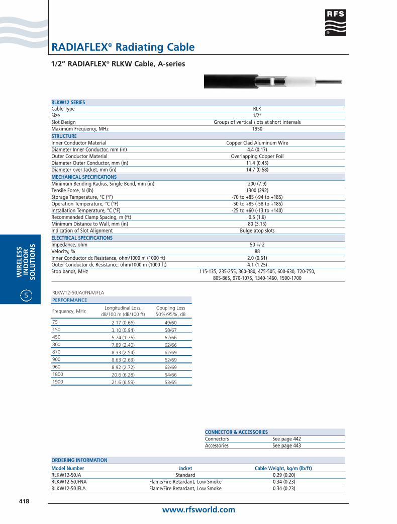
Model Number Jacket Cable Weight, kg/m (lb/ft)RLKW12-50JA Standard 0.29 (0.20)RLKW12-50JFNA Flame/Fire Retardant, Low Smoke 0.34 (0.23)RLKW12-50JFLA Flame/Fire Retardant, Low Smoke 0.34 (0.23)
ORDERING INFORMATION
Cable Type RLKSize 1/2”Slot Design Groups of vertical slots at short intervalsMaximum Frequency, MHz 1950STRUCTUREInner Conductor Material Copper Clad Aluminum WireDiameter Inner Conductor, mm (in) 4.4 (0.17)Outer Conductor Material Overlapping Copper FoilDiameter Outer Conductor, mm (in) 11.4 (0.45)Diameter over Jacket, mm (in) 14.7 (0.58)MECHANICAL SPECIFICATIONSMinimum Bending Radius, Single Bend, mm (in) 200 (7.9)Tensile Force, N (lb) 1300 (292)Storage Temperature, °C (°F) -70 to +85 (-94 to +185)Operation Temperature, °C (°F) -50 to +85 (-58 to +185)Installation Temperature, °C (°F) -25 to +60 (-13 to +140)Recommended Clamp Spacing, m (ft) 0.5 (1.6)Minimum Distance to Wall, mm (in) 80 (3.15)Indication of Slot Alignment Bulge atop slotsELECTRICAL SPECIFICATIONSImpedance, ohm 50 +/-2Velocity, % 88Inner Conductor dc Resistance, ohm/1000 m (1000 ft) 2.0 (0.61)Outer Conductor dc Resistance, ohm/1000 m (1000 ft) 4.1 (1.25)Stop bands, MHz 115-135, 235-255, 360-380, 475-505, 600-630, 720-750,
805-865, 970-1075, 1340-1460, 1590-1700
RLKW12 SERIES
RLKW12-50JA/JFNA/JFLA
PERFORMANCE
Frequency, MHzLongitudinal Loss,
dB/100 m (dB/100 ft)Coupling Loss 50%/95%, dB
75 2.17 (0.66) 49/60150 3.10 (0.94) 58/67450 5.74 (1.75) 62/66800 7.89 (2.40) 62/66870 8.33 (2.54) 62/69900 8.63 (2.63) 62/69960 8.92 (2.72) 62/691800 20.6 (6.28) 54/661900 21.6 (6.59) 53/65
www.rfsworld.com419
WIR
ELESSIN
DO
OR
SOLU
TION
S
5
RADIAFLEX® Radiating Cable1/2” RADIAFLEX® RLKU Cable, A-series
CONNECTOR & ACCESSORIESConnectors See page 442Accessories See page 443
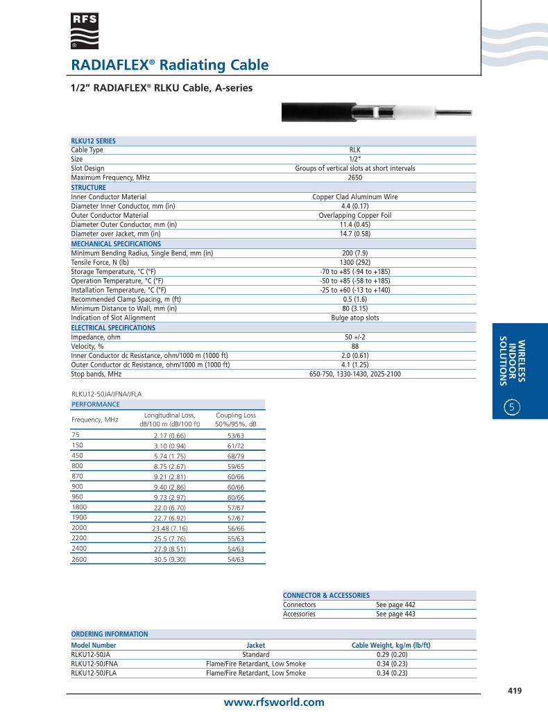
Model Number Jacket Cable Weight, kg/m (lb/ft)RLKU12-50JA Standard 0.29 (0.20)RLKU12-50JFNA Flame/Fire Retardant, Low Smoke 0.34 (0.23)RLKU12-50JFLA Flame/Fire Retardant, Low Smoke 0.34 (0.23)
ORDERING INFORMATION
Cable Type RLKSize 1/2”Slot Design Groups of vertical slots at short intervalsMaximum Frequency, MHz 2650STRUCTUREInner Conductor Material Copper Clad Aluminum WireDiameter Inner Conductor, mm (in) 4.4 (0.17)Outer Conductor Material Overlapping Copper FoilDiameter Outer Conductor, mm (in) 11.4 (0.45)Diameter over Jacket, mm (in) 14.7 (0.58)MECHANICAL SPECIFICATIONSMinimum Bending Radius, Single Bend, mm (in) 200 (7.9)Tensile Force, N (lb) 1300 (292)Storage Temperature, °C (°F) -70 to +85 (-94 to +185)Operation Temperature, °C (°F) -50 to +85 (-58 to +185)Installation Temperature, °C (°F) -25 to +60 (-13 to +140)Recommended Clamp Spacing, m (ft) 0.5 (1.6)Minimum Distance to Wall, mm (in) 80 (3.15)Indication of Slot Alignment Bulge atop slotsELECTRICAL SPECIFICATIONSImpedance, ohm 50 +/-2Velocity, % 88Inner Conductor dc Resistance, ohm/1000 m (1000 ft) 2.0 (0.61)Outer Conductor dc Resistance, ohm/1000 m (1000 ft) 4.1 (1.25)Stop bands, MHz 650-750, 1330-1430, 2025-2100
RLKU12 SERIES
RLKU12-50JA/JFNA/JFLA
PERFORMANCE
Frequency, MHzLongitudinal Loss,
dB/100 m (dB/100 ft)Coupling Loss 50%/95%, dB
75 2.17 (0.66) 53/63150 3.10 (0.94) 61/72450 5.74 (1.75) 68/79800 8.75 (2.67) 59/65870 9.21 (2.81) 60/66900 9.40 (2.86) 60/66960 9.73 (2.97) 60/661800 22.0 (6.70) 57/671900 22.7 (6.92) 57/672000 23.48 (7.16) 56/662200 25.5 (7.76) 55/632400 27.9 (8.51) 54/63
2600 30.5 (9.30) 54/63

www.rfsworld.com420
5
WIR
ELES
SIN
DO
OR
SOLU
TIO
NS
RADIAFLEX® Radiating Cable7/8” RADIAFLEX® RLKL Cable, A-series
CONNECTOR & ACCESSORIESConnectors See page 442Accessories See page 443
Model Number Jacket Cable Weight, kg/m (lb/ft)RLKL78-50JA Standard 0.45 (0.30)RLKL78-50JFNA Flame/Fire Retardant 0.60 (0.40)RLKL78-50JFLA Flame/Fire Retardant, Low Smoke 0.60 (0.40)
ORDERING INFORMATION
Cable Type RLKSize 7/8”Slot Design Groups of vertical slots at short intervalsMaximum Frequency, MHz 600STRUCTUREInner Conductor Material Copper TubeDiameter Inner Conductor, mm (in) 9.3 (0.37)Outer Conductor Material Overlapping Copper FoilDiameter Outer Conductor, mm (in) 23.8 (0.94)Diameter over Jacket, mm (in) 28.5 (1.12)MECHANICAL SPECIFICATIONSMinimum Bending Radius, Single Bend, mm (in) 350 (13.8)Tensile Force, N (lb) 2300 (507)Storage Temperature, °C (°F) -70 to +85 (-94 to +185)Operation Temperature, °C (°F) -50 to +85 (-58 to +185)Installation Temperature, °C (°F) -25 to +60 (-13 to +140)Recommended Clamp Spacing, m (ft) 0.9 (3)Minimum Distance to Wall, mm (in) 80 (3.15)Indication of Slot Alignment Bulge atop slotsELECTRICAL SPECIFICATIONSImpedance, ohm 50 +/-2Velocity, % 89Inner Conductor dc Resistance, ohm/1000 m (1000 ft) 1.46 (0.44)Outer Conductor dc Resistance, ohm/1000 m (1000 ft) 2.16 (0.66)Stop bands, MHz 55-65, 115-130, 175-190, 235-250, 295-310, 355-375, 535-555
RLKL78 SERIES
RLKL78-50JA/JFNA/JFLA
PERFORMANCE
Frequency, MHzLongitudinal Loss,
dB/100 m (dB/100 ft)Coupling Loss 50%/95%, dB
75 1.00 (0.30) 50/59150 1.48 (0.45) 56/63450 2.83 (0.86) 60/69
www.rfsworld.com421
WIR
ELESSIN
DO
OR
SOLU
TION
S
5
RADIAFLEX® Radiating Cable7/8” RADIAFLEX® RLKW Cable, A-series
CONNECTOR & ACCESSORIESConnectors See page 442Accessories See page 443
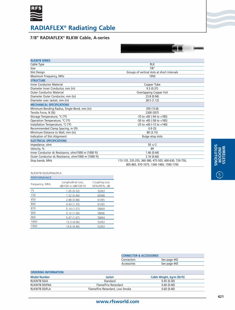
Model Number Jacket Cable Weight, kg/m (lb/ft)RLKW78-50JA Standard 0.45 (0.30)RLKW78-50JFNA Flame/Fire Retardant 0.60 (0.40)RLKW78-50JFLA Flame/Fire Retardant, Low Smoke 0.60 (0.40)
ORDERING INFORMATION
Cable Type RLKSize 7/8”Slot Design Groups of vertical slots at short intervalsMaximum Frequency, MHz 1950STRUCTUREInner Conductor Material Copper TubeDiameter Inner Conductor, mm (in) 9.3 (0.37)Outer Conductor Material Overlapping Copper FoilDiameter Outer Conductor, mm (in) 23.8 (0.94)Diameter over Jacket, mm (in) 28.5 (1.12)MECHANICAL SPECIFICATIONSMinimum Bending Radius, Single Bend, mm (in) 350 (13.8)Tensile Force, N (lb) 2300 (507)Storage Temperature, °C (°F) -70 to +85 (-94 to +185)Operation Temperature, °C (°F) -50 to +85 (-58 to +185)Installation Temperature, °C (°F) -25 to +60 (-13 to +140)Recommended Clamp Spacing, m (ft) 0.9 (3)Minimum Distance to Wall, mm (in) 80 (3.15)Indication of Slot Alignment Bulge atop slotsELECTRICAL SPECIFICATIONSImpedance, ohm 50 +/-2Velocity, % 89Inner Conductor dc Resistance, ohm/1000 m (1000 ft) 1.46 (0.44)Outer Conductor dc Resistance, ohm/1000 m (1000 ft) 2.16 (0.66)Stop bands, MHz 115-135, 235-255, 360-380, 475-505, 600-630, 720-750,
805-865, 970-1075, 1340-1460, 1590-1700
RLKW78 SERIES
RLKW78-50JA/JFNA/JFLA
PERFORMANCE
Frequency, MHzLongitudinal Loss,
dB/100 m (dB/100 ft)Coupling Loss 50%/95%, dB
75 1.05 (0.32) 52/63150 1.52 (0.46) 60/68450 2.88 (0.88) 61/65800 4.44 (1.35) 61/65870 5.14 (1.57) 58/64900 5.12 (1.56) 58/66960 5.47 (1.67) 58/641800 13.3 (4.06) 52/631900 14.6 (4.46) 52/63
www.rfsworld.com422
5
WIR
ELES
SIN
DO
OR
SOLU
TIO
NS
RADIAFLEX® Radiating Cable7/8” RADIAFLEX® RLKU Cable, A-series
CONNECTOR & ACCESSORIESConnectors See page 442Accessories See page 443
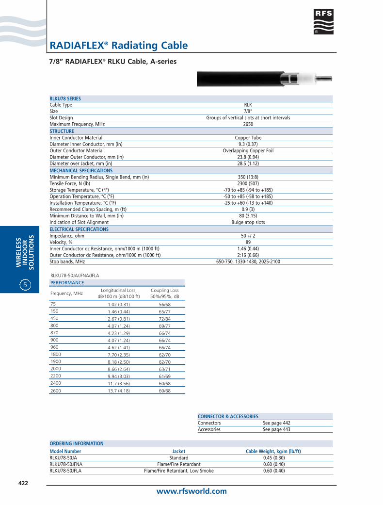
Model Number Jacket Cable Weight, kg/m (lb/ft)RLKU78-50JA Standard 0.45 (0.30)RLKU78-50JFNA Flame/Fire Retardant 0.60 (0.40)RLKU78-50JFLA Flame/Fire Retardant, Low Smoke 0.60 (0.40)
ORDERING INFORMATION
Cable Type RLKSize 7/8”Slot Design Groups of vertical slots at short intervalsMaximum Frequency, MHz 2650STRUCTUREInner Conductor Material Copper TubeDiameter Inner Conductor, mm (in) 9.3 (0.37)Outer Conductor Material Overlapping Copper FoilDiameter Outer Conductor, mm (in) 23.8 (0.94)Diameter over Jacket, mm (in) 28.5 (1.12)MECHANICAL SPECIFICATIONSMinimum Bending Radius, Single Bend, mm (in) 350 (13:8)Tensile Force, N (lb) 2300 (507)Storage Temperature, °C (°F) -70 to +85 (-94 to +185)Operation Temperature, °C (°F) -50 to +85 (-58 to +185)Installation Temperature, °C (°F) -25 to +60 (-13 to +140)Recommended Clamp Spacing, m (ft) 0.9 (3)Minimum Distance to Wall, mm (in) 80 (3.15)Indication of Slot Alignment Bulge atop slotsELECTRICAL SPECIFICATIONSImpedance, ohm 50 +/-2Velocity, % 89Inner Conductor dc Resistance, ohm/1000 m (1000 ft) 1.46 (0.44)Outer Conductor dc Resistance, ohm/1000 m (1000 ft) 2:16 (0.66)Stop bands, MHz 650-750, 1330-1430, 2025-2100
RLKU78 SERIES
RLKU78-50JA/JFNA/JFLA
PERFORMANCE
Frequency, MHzLongitudinal Loss,
dB/100 m (dB/100 ft)Coupling Loss 50%/95%, dB
75 1.02 (0.31) 56/68150 1.46 (0.44) 65/77450 2.67 (0.81) 72/84800 4.07 (1.24) 69/77870 4.23 (1.29) 66/74900 4.07 (1.24) 66/74960 4.62 (1.41) 66/741800 7.70 (2.35) 62/701900 8.18 (2.50) 62/702000 8.66 (2.64) 63/712200 9.94 (3.03) 61/692400 11.7 (3.56) 60/68
2600 13.7 (4.18) 60/68

www.rfsworld.com423
WIR
ELESSIN
DO
OR
SOLU
TION
S
5
RADIAFLEX® Radiating Cable1-1/4” RADIAFLEX® RLKL Cable, A-series
CONNECTOR & ACCESSORIESConnectors See page 442Accessories See page 443
Model Number Jacket Cable Weight, kg/m (lb/ft)RLKL114-50JA Standard 0.66 (0.44)RLKL114-50JFNA Flame/Fire Retardant 0.90 (0.60)RLKL114-50JFLA Flame/Fire Retardant, Low Smoke 0.90 (0.60)
ORDERING INFORMATION
Cable Type RLKSize 1-1/4”Slot Design Groups of vertical slots at short intervalsMaximum Frequency, MHz 600STRUCTUREInner Conductor Material Copper TubeDiameter Inner Conductor, mm (in) 13.1 (0.52)Outer Conductor Material Overlapping Copper FoilDiameter Outer Conductor, mm (in) 34.0 (1.34)Diameter over Jacket, mm (in) 38.1 (1.50)MECHANICAL SPECIFICATIONSMinimum Bending Radius, Single Bend, mm (in) 500 (20.0)Tensile Force, N (lb) 2000 (440)Storage Temperature, °C (°F) -70 to +85 (-94 to +185)Operation Temperature, °C (°F) -50 to +85 (-58 to +185)Installation Temperature, °C (°F) -25 to +60 (-13 to +140)Recommended Clamp Spacing, m (ft) 1.3 (4.25)Minimum Distance to Wall, mm (in) 80 (3.15)Indication of Slot Alignment Bulge atop slotsELECTRICAL SPECIFICATIONSImpedance, ohm 50 +/-2Velocity, % 89Inner Conductor dc Resistance, ohm/1000 m (1000 ft) 0.80 (0.24)Outer Conductor dc Resistance, ohm/1000 m (1000 ft) 1.75 (0.53)Stop bands, MHz 55-65, 115-130, 175-190, 235-250, 295-310, 355-375, 535-
555
RLKL114 SERIES
RLKL114-50JA/JFNA/JFLA
PERFORMANCE
Frequency, MHzLongitudinal Loss,
dB/100 m (dB/100 ft)Coupling Loss 50%/95%, dB
75 0.80 (0.24) 55/66150 1.00 (0.31) 60/68450 2.10 (0.64) 64/68
www.rfsworld.com424
5
WIR
ELES
SIN
DO
OR
SOLU
TIO
NS
RADIAFLEX® Radiating Cable1-1/4” RADIAFLEX® RLK Cable, A-series
CONNECTOR & ACCESSORIESConnectors See page 442Accessories See page 443
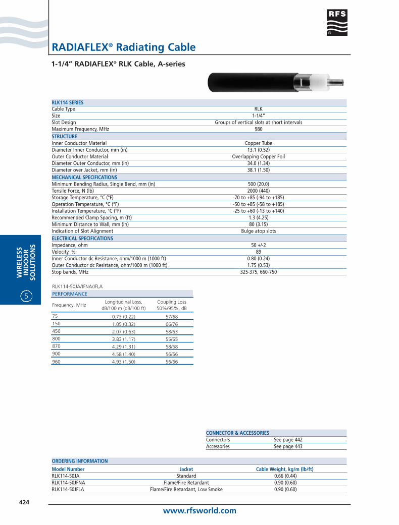
Model Number Jacket Cable Weight, kg/m (lb/ft)RLK114-50JA Standard 0.66 (0.44)RLK114-50JFNA Flame/Fire Retardant 0.90 (0.60)RLK114-50JFLA Flame/Fire Retardant, Low Smoke 0.90 (0.60)
ORDERING INFORMATION
Cable Type RLKSize 1-1/4”Slot Design Groups of vertical slots at short intervalsMaximum Frequency, MHz 980STRUCTUREInner Conductor Material Copper TubeDiameter Inner Conductor, mm (in) 13.1 (0.52)Outer Conductor Material Overlapping Copper FoilDiameter Outer Conductor, mm (in) 34.0 (1.34)Diameter over Jacket, mm (in) 38.1 (1.50)MECHANICAL SPECIFICATIONSMinimum Bending Radius, Single Bend, mm (in) 500 (20.0)Tensile Force, N (lb) 2000 (440)Storage Temperature, °C (°F) -70 to +85 (-94 to +185)Operation Temperature, °C (°F) -50 to +85 (-58 to +185)Installation Temperature, °C (°F) -25 to +60 (-13 to +140)Recommended Clamp Spacing, m (ft) 1.3 (4.25)Minimum Distance to Wall, mm (in) 80 (3.15)Indication of Slot Alignment Bulge atop slotsELECTRICAL SPECIFICATIONSImpedance, ohm 50 +/-2Velocity, % 89Inner Conductor dc Resistance, ohm/1000 m (1000 ft) 0.80 (0.24)Outer Conductor dc Resistance, ohm/1000 m (1000 ft) 1.75 (0.53)Stop bands, MHz 325-375, 660-750
RLK114 SERIES
RLK114-50JA/JFNA/JFLA
PERFORMANCE
Frequency, MHzLongitudinal Loss,
dB/100 m (dB/100 ft)Coupling Loss 50%/95%, dB
75 0.73 (0.22) 57/68150 1.05 (0.32) 66/76450 2.07 (0.63) 58/63800 3.83 (1.17) 55/65870 4.29 (1.31) 58/68900 4.58 (1.40) 56/66
960 4.93 (1.50) 56/66
www.rfsworld.com425
WIR
ELESSIN
DO
OR
SOLU
TION
S
5
RADIAFLEX® Radiating Cable1-1/4” RADIAFLEX® RLKW Cable, A-series
CONNECTOR & ACCESSORIESConnectors See page 442Accessories See page 443
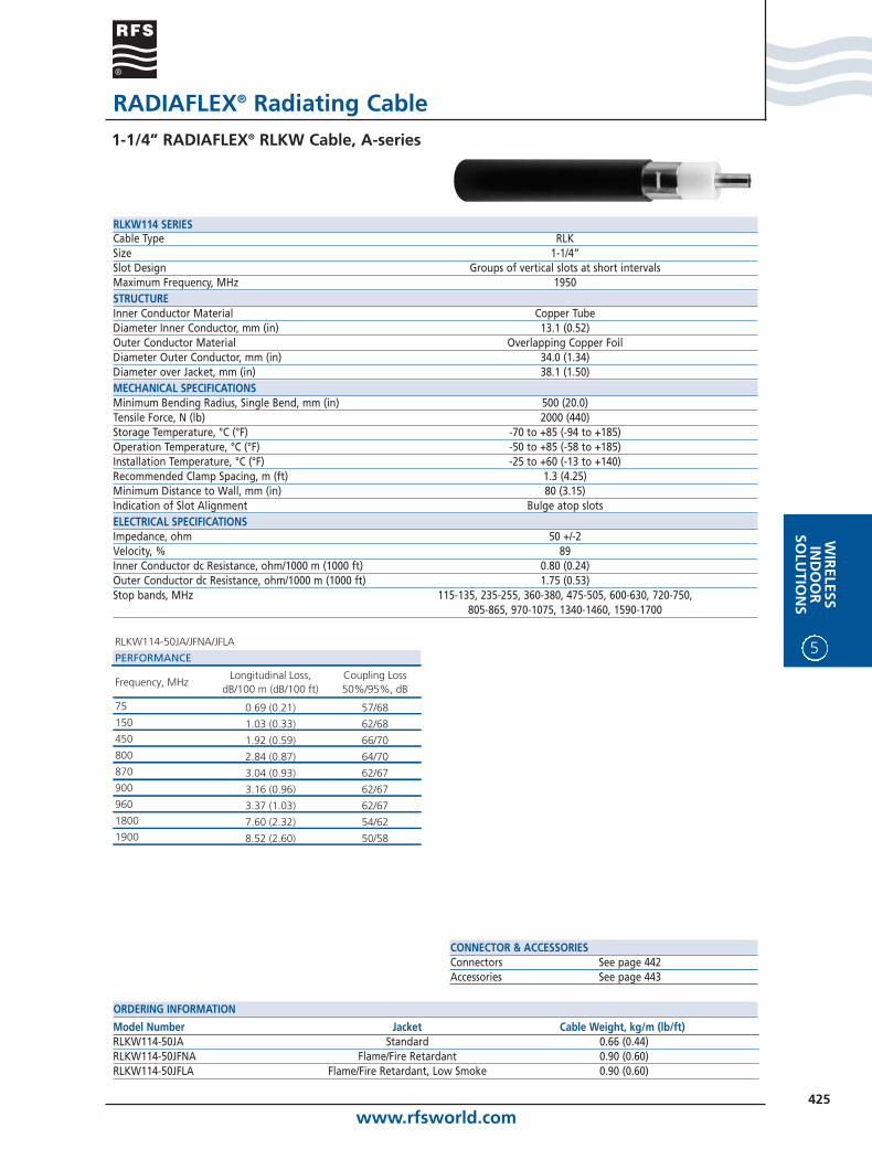
Model Number Jacket Cable Weight, kg/m (lb/ft)RLKW114-50JA Standard 0.66 (0.44)RLKW114-50JFNA Flame/Fire Retardant 0.90 (0.60)RLKW114-50JFLA Flame/Fire Retardant, Low Smoke 0.90 (0.60)
ORDERING INFORMATION
Cable Type RLKSize 1-1/4”Slot Design Groups of vertical slots at short intervalsMaximum Frequency, MHz 1950STRUCTUREInner Conductor Material Copper TubeDiameter Inner Conductor, mm (in) 13.1 (0.52)Outer Conductor Material Overlapping Copper FoilDiameter Outer Conductor, mm (in) 34.0 (1.34)Diameter over Jacket, mm (in) 38.1 (1.50)MECHANICAL SPECIFICATIONSMinimum Bending Radius, Single Bend, mm (in) 500 (20.0)Tensile Force, N (lb) 2000 (440)Storage Temperature, °C (°F) -70 to +85 (-94 to +185)Operation Temperature, °C (°F) -50 to +85 (-58 to +185)Installation Temperature, °C (°F) -25 to +60 (-13 to +140)Recommended Clamp Spacing, m (ft) 1.3 (4.25)Minimum Distance to Wall, mm (in) 80 (3.15)Indication of Slot Alignment Bulge atop slotsELECTRICAL SPECIFICATIONSImpedance, ohm 50 +/-2Velocity, % 89Inner Conductor dc Resistance, ohm/1000 m (1000 ft) 0.80 (0.24)Outer Conductor dc Resistance, ohm/1000 m (1000 ft) 1.75 (0.53)Stop bands, MHz 115-135, 235-255, 360-380, 475-505, 600-630, 720-750,
805-865, 970-1075, 1340-1460, 1590-1700
RLKW114 SERIES
RLKW114-50JA/JFNA/JFLA
PERFORMANCE
Frequency, MHzLongitudinal Loss,
dB/100 m (dB/100 ft)Coupling Loss 50%/95%, dB
75 0.69 (0.21) 57/68150 1.03 (0.33) 62/68450 1.92 (0.59) 66/70800 2.84 (0.87) 64/70870 3.04 (0.93) 62/67900 3.16 (0.96) 62/67960 3.37 (1.03) 62/671800 7.60 (2.32) 54/621900 8.52 (2.60) 50/58

www.rfsworld.com426
5
WIR
ELES
SIN
DO
OR
SOLU
TIO
NS
RADIAFLEX® Radiating Cable1-1/4” RADIAFLEX® RLKU Cable, A-series
CONNECTOR & ACCESSORIESConnectors See page 442Accessories See page 443
Model Number Jacket Cable Weight, kg/m (lb/ft)RLKU114-50JA Standard 0.66 (0.44)RLKU114-50JFNA Flame/Fire Retardant 0.90 (0.60)RLKU114-50JFLA Flame/Fire Retardant, Low Smoke 0.90 (0.60)
ORDERING INFORMATION
Cable Type RLKSize 1-1/4”Slot Design Groups of vertical slots at short intervalsMaximum Frequency, MHz 2650STRUCTUREInner Conductor Material Copper TubeDiameter Inner Conductor, mm (in) 13.1 (0.52)Outer Conductor Material Overlapping Copper FoilDiameter Outer Conductor, mm (in) 34.0 (1.34)Diameter over Jacket, mm (in) 38.1 (1.50)MECHANICAL SPECIFICATIONSMinimum Bending Radius, Single Bend, mm (in) 500 (20.0)Tensile Force, N (lb) 2000 (440)Storage Temperature, °C (°F) -70 to +85 (-94 to +185)Operation Temperature, °C (°F) -50 to +85 (-58 to +185)Installation Temperature, °C (°F) -25 to +60 (-13 to +140)Recommended Clamp Spacing, m (ft) 1.3 (4.25)Minimum Distance to Wall, mm (in) 80 (3.15)Indication of Slot Alignment Guides opposite to slotsELECTRICAL SPECIFICATIONSImpedance, ohm 50 +/-2Velocity, % 89Inner Conductor dc Resistance, ohm/1000 m (1000 ft) 0.80 (0.24)Outer Conductor dc Resistance, ohm/1000 m (1000 ft) 1.75 (0.53)Stop bands, MHz 650-750, 1330-1430, 2025-2100
RLKU114 SERIES
RLKU114-50JA/JFNA/JFLA
PERFORMANCE
Frequency, MHzLongitudinal Loss,
dB/100 m (dB/100 ft)Coupling Loss 50%/95%, dB
75 0.70 (0.21) 57/69150 1.03 (0.31) 66/78450 1.90 (0.58) 75/87800 2.86 (0.87) 67/72870 3.06 (0.93) 67/73900 3.06 (0.93) 67/72960 3.27 (1.00) 67/721800 5.51 (1.68) 63/681900 5.80 (1.77) 63/682000 6.15 (1.87) 62/672200 7.24 (2.21) 62/672400 8.29 (2.53) 62/67
2600 10.0 (3.05) 61/66

www.rfsworld.com427
WIR
ELESSIN
DO
OR
SOLU
TION
S
5
RADIAFLEX® Radiating Cable1-5/8” RADIAFLEX® RLKU Cable, A-series
CONNECTOR & ACCESSORIESConnectors See page 442Accessories See page 443
Model Number Jacket Cable Weight, kg/m (lb/ft)RLKU158-50JA Standard 0.80 (0.54)RLKU158-50JFNA Flame/Fire Retardant 1.10 (0.74)RLKU158-50JFLA Flame/Fire Retardant, Low Smoke 1.10 (0.74)
ORDERING INFORMATION
Cable Type RLKSize 1-5/8”Slot Design Groups of vertical slots at short intervalsMaximum Frequency, MHz 2650STRUCTUREInner Conductor Material Corrugated Copper TubeDiameter Inner Conductor, mm (in) 17.6 (0.69)Outer Conductor Material Overlapping Copper FoilDiameter Outer Conductor, mm (in) 44.2 (1.74)Diameter over Jacket, mm (in) 48.2 (1.90)MECHANICAL SPECIFICATIONSMinimum Bending Radius, Single Bend, mm (in) 700 (28.0)Tensile Force, N (lb) 1200 (270)Storage Temperature, °C (°F) -70 to +85 (-94 to +185)Operation Temperature, °C (°F) -50 to +85 (-58 to +185)Installation Temperature, °C (°F) -25 to +60 (-13 to +140)Recommended Clamp Spacing, m (ft) 1.5 (5)Minimum Distance to Wall, mm (in) 80 (3.15)Indication of Slot Alignment Guides opposite to slotsELECTRICAL SPECIFICATIONSImpedance, ohm 50 +/-2Velocity, % 89Inner Conductor dc Resistance, ohm/1000 m (1000 ft) 1.30 (0.40)Outer Conductor dc Resistance, ohm/1000 m (1000 ft) 1.30 (0.40)Stop bands, MHz 650-750, 1000-1050, 1330-1430, 2025-2100
RLKU158 SERIES
RLKU158-50JA/JFNA/JFLA
PERFORMANCE
Frequency, MHzLongitudinal Loss,
dB/100 m (dB/100 ft)Coupling Loss 50%/95%, dB
75 0.54 (0.17) 65/77150 0.77 (0.24) 74/84450 1.43 (0.44) 84/92800 2.10 (0.64) 68/71870 2.22 (0.68) 68/72900 2.25 (0.69) 68/721800 3.85 (1.17) 64/691900 4.06 (1.24) 64/702000 4.29 (1.31) 65/712200 4.87 (1.48) 63/682400 5.52 (1.68) 61/66
2600 6.39 (1.95) 61/66

www.rfsworld.com428
5
WIR
ELES
SIN
DO
OR
SOLU
TIO
NS
RADIAFLEX® Radiating Cable1-1/4” RADIAFLEX® RLV Cable, A-series
CONNECTOR & ACCESSORIESConnectors See page 442Accessories See page 443
Model Number Jacket Cable Weight, kg/m (lb/ft)RLV114-50JA Standard 0.66 (0.44)RLV114-50JFNA Flame/Fire Retardant 0.90 (0.60)RLV114-50JFLA Flame/Fire Retardant, Low Smoke 0.90 (0.60)
ORDERING INFORMATION
Cable Type RLVSize 1-1/4”Length, m (ft) 1000 (3281)Slot Design Groups of vertical slots of increasing densityMaximum Frequency, MHz 1000STRUCTUREInner Conductor Material Copper TubeDiameter Inner Conductor, mm (in) 13.1 (0.52)Outer Conductor Material Overlapping Copper FoilDiameter Outer Conductor, mm (in) 34.0 (1.34)Diameter over Jacket, mm (in) 38.1 (1.50)MECHANICAL SPECIFICATIONSMinimum Bending Radius, Single Bend, mm (in) 500 (20.0)Tensile Force, N (lb) 2000 (440)Storage Temperature, °C (°F) -70 to +85 (-94 to +185)Operation Temperature, °C (°F) -50 to +85 (-58 to +185)Installation Temperature, °C (°F) -25 to +60 (-13 to +140)Recommended Clamp Spacing, m (ft) 1.3 (4.25)Minimum Distance to Wall, mm (in) 80 (3.15)Indication of Slot Alignment Bulge atop slotsELECTRICAL SPECIFICATIONSImpedance, ohm 50 +/-2Velocity, % 89Inner Conductor dc Resistance, ohm/1000 m (1000 ft) 0.80 (0.24)Outer Conductor dc Resistance, ohm/1000 m (1000 ft) 1.75 (0.54)Stop bands, MHz 720-840
RLV114 SERIES
RLV114-50JA/JFNA/JFLA
PERFORMANCE
Frequency, MHzLongitudinal Loss of
Cable Length, dBSystem Loss
50%/95%, dB
150 11.1 85/97450 19.7 96/108900 34.2 89/97960 35.5 91/99
Data for other cable lengths available upon request.

www.rfsworld.com429
WIR
ELESSIN
DO
OR
SOLU
TION
S
5
RADIAFLEX® Radiating Cable1-1/4” RADIAFLEX® RLVU Cable, A-series
CONNECTOR & ACCESSORIESConnectors See page 442Accessories See page 443
Model Number Jacket Cable Weight, kg/m (lb/ft)RLVU114-50JA Standard 0.66 (0.44)RLVU114-50JFNA Flame/Fire Retardant 0.90 (0.60)RLVU114-50JFLA Flame/Fire Retardant, Low Smoke 0.90 (0.60)
ORDERING INFORMATION
Cable Type RLVSize 1-1/4”Length, m (ft) 500 (1641)Slot Design Groups of vertical slots of increasing densityMaximum Frequency, MHz 2400STRUCTUREInner Conductor Material Copper TubeDiameter Inner Conductor, mm (in) 13.1 (0.52)Outer Conductor Material Overlapping Copper FoilDiameter Outer Conductor, mm (in) 34.0 (1.34)Diameter over Jacket, mm (in) 38.1 (1.50)MECHANICAL SPECIFICATIONSMinimum Bending Radius, Single Bend, mm (in) 500 (20.0)Tensile Force, N (lb) 2000 (440)Storage Temperature, °C (°F) -70 to +85 (-94 to +185)Operation Temperature, °C (°F) -50 to +85 (-58 to +185)Installation Temperature, °C (°F) -25 to +60 (-13 to +140)Recommended Clamp Spacing, m (ft) 1.3 (4.25)Minimum Distance to Wall, mm (in) 80 (3.15)Indication of Slot Alignment Guides opposite to slotsELECTRICAL SPECIFICATIONSImpedance, ohm 50 +/-2Velocity, % 89Inner Conductor dc Resistance, ohm/1000 m (1000 ft) 0.80 (0.24)Outer Conductor dc Resistance, ohm/1000 m (1000 ft) 1.75 (0.54)Stop bands, MHz 790-870, 1550-1650
RLVU114 SERIES
RLVU114-50JA/JFNA/JFLA
PERFORMANCE
Frequency, MHzLongitudinal Loss of
Cable Length, dBSystem Loss
50%/95%, dB
450 10.0 103/108900 16.0 78/831800 24.0 88/932000 26.0 89/942200 29.0 90/952400 34.0 97/102
Data for other cable lengths available upon request.
www.rfsworld.com430
5
WIR
ELES
SIN
DO
OR
SOLU
TIO
NS
RADIAFLEX® Radiating Cable1-1/4” RADIAFLEX® RLVU Cable, A-series
CONNECTOR & ACCESSORIESConnectors See page 442Accessories See page 443
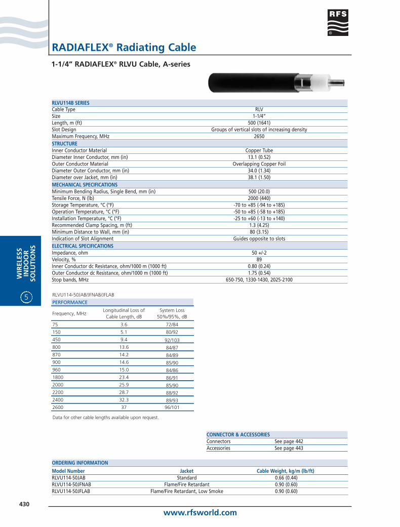
Model Number Jacket Cable Weight, kg/m (lb/ft)RLVU114-50JAB Standard 0.66 (0.44)RLVU114-50JFNAB Flame/Fire Retardant 0.90 (0.60)RLVU114-50JFLAB Flame/Fire Retardant, Low Smoke 0.90 (0.60)
ORDERING INFORMATION
Cable Type RLVSize 1-1/4”Length, m (ft) 500 (1641)Slot Design Groups of vertical slots of increasing densityMaximum Frequency, MHz 2650STRUCTUREInner Conductor Material Copper TubeDiameter Inner Conductor, mm (in) 13.1 (0.52)Outer Conductor Material Overlapping Copper FoilDiameter Outer Conductor, mm (in) 34.0 (1.34)Diameter over Jacket, mm (in) 38.1 (1.50)MECHANICAL SPECIFICATIONSMinimum Bending Radius, Single Bend, mm (in) 500 (20.0)Tensile Force, N (lb) 2000 (440)Storage Temperature, °C (°F) -70 to +85 (-94 to +185)Operation Temperature, °C (°F) -50 to +85 (-58 to +185)Installation Temperature, °C (°F) -25 to +60 (-13 to +140)Recommended Clamp Spacing, m (ft) 1.3 (4.25)Minimum Distance to Wall, mm (in) 80 (3.15)Indication of Slot Alignment Guides opposite to slotsELECTRICAL SPECIFICATIONSImpedance, ohm 50 +/-2Velocity, % 89Inner Conductor dc Resistance, ohm/1000 m (1000 ft) 0.80 (0.24)Outer Conductor dc Resistance, ohm/1000 m (1000 ft) 1.75 (0.54)Stop bands, MHz 650-750, 1330-1430, 2025-2100
RLVU114B SERIES
RLVU114-50JAB/JFNAB/JFLAB
PERFORMANCE
Frequency, MHzLongitudinal Loss of
Cable Length, dBSystem Loss
50%/95%, dB
75 3.6 72/84
150 5.1 80/92
450 9.4 92/103800 13.6 84/87870 14.2 84/89900 14.6 85/90960 15.0 84/861800 23.4 86/912000 25.9 85/902200 28.7 88/922400 32.3 89/932600 37 96/101
Data for other cable lengths available upon request.

www.rfsworld.com431
WIR
ELESSIN
DO
OR
SOLU
TION
S
5
RADIAFLEX® Radiating Cable1-5/8” RADIAFLEX® RLV Cable, A-series
CONNECTOR & ACCESSORIESConnectors See page 442Accessories See page 443
Model Number Jacket Cable Weight, kg/m (lb/ft)RLV158-50JA Standard 0.80 (0.54)RLV158-50JFNA Flame/Fire Retardant 1.10 (0.74)RLV158-50JFLA Flame/Fire Retardant, Low Smoke 1.10 (0.74)
ORDERING INFORMATION
Cable Type RLVSize 1-5/8”Length, m (ft) 1000 (3281)Slot Design Groups of vertical slots of increasing densityMaximum Frequency, MHz 1000STRUCTUREInner Conductor Material Corrugated Copper TubeDiameter Inner Conductor, mm (in) 17.6 (0.69)Outer Conductor Material Overlapping Copper FoilDiameter Outer Conductor, mm (in) 44.2 (1.74)Diameter over Jacket, mm (in) 48.2 (1.90)MECHANICAL SPECIFICATIONSMinimum Bending Radius, Single Bend, mm (in) 700 (28.0)Tensile Force, N (lb) 1200 (270)Storage Temperature, °C (°F) -70 to +85 (-94 to +185)Operation Temperature, °C (°F) -50 to +85 (-58 to +185)Installation Temperature, °C (°F) -25 to +60 (-13 to +140)Recommended Clamp Spacing, m (ft) 1.5 (5)Minimum Distance to Wall, mm (in) 80 (3.15)Indication of Slot Alignment Guides opposite to slotsELECTRICAL SPECIFICATIONSImpedance, ohm 50 +/-2Velocity, % 89Inner Conductor dc Resistance, ohm/1000 m (1000 ft) 1.30 (0.40)Outer Conductor dc Resistance, ohm/1000 m (1000 ft) 1.30 (0.40)Stop bands, MHz 720-840
RLV158 SERIES
RLV158-50JA/JFNA/JFLA
PERFORMANCE
Frequency, MHzLongitudinal Loss of
Cable Length, dBSystem Loss
50%/95%, dB
450 16.0 94/105870 30.0 80/85900 30.7 83/88960 31.6 84/89
Data for other cable lengths available upon request.
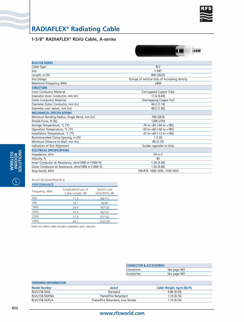
www.rfsworld.com432
5
WIR
ELES
SIN
DO
OR
SOLU
TIO
NS
RADIAFLEX® Radiating Cable1-5/8” RADIAFLEX® RLVU Cable, A-series
CONNECTOR & ACCESSORIESConnectors See page 442Accessories See page 443
Model Number Jacket Cable Weight, kg/m (lb/ft)RLVU158-50JA Standard 0.80 (0.54)RLVU158-50JFNA Flame/Fire Retardant 1.10 (0.74)RLVU158-50JFLA Flame/Fire Retardant, Low Smoke 1.10 (0.74)
ORDERING INFORMATION
Cable Type RLVSize 1-5/8”Length, m (ft) 800 (2625)Slot Design Groups of vertical slots of increasing densityMaximum Frequency, MHz 2400STRUCTUREInner Conductor Material Corrugated Copper TubeDiameter Inner Conductor, mm (in) 17.6 (0.69)Outer Conductor Material Overlapping Copper FoilDiameter Outer Conductor, mm (in) 44.2 (1.74)Diameter over Jacket, mm (in) 48.2 (1.90)MECHANICAL SPECIFICATIONSMinimum Bending Radius, Single Bend, mm (in) 700 (28.0)Tensile Force, N (lb) 1200 (270)Storage Temperature, °C (°F) -70 to +85 (-94 to +185)Operation Temperature, °C (°F) -50 to +85 (-58 to +185)Installation Temperature, °C (°F) -25 to +60 (-13 to +140)Recommended Clamp Spacing, m (ft) 1.5 (5)Minimum Distance to Wall, mm (in) 80 (3.15)Indication of Slot Alignment Guides opposite to slotsELECTRICAL SPECIFICATIONSImpedance, ohm 50 +/-2Velocity, % 89Inner Conductor dc Resistance, ohm/1000 m (1000 ft) 1.30 (0.40)Outer Conductor dc Resistance, ohm/1000 m (1000 ft) 1.30 (0.40)Stop bands, MHz 790-870, 1000-1050, 1550-1650
RLVU158 SERIES
RLVU158-50JA/JFNA/JFLA
PERFORMANCE
Frequency, MHzLongitudinal Loss of
Cable Length, dBSystem Loss
50%/95%, dB
450 11.5 99/111900 18.1 82/871800 29.9 95/1002000 33.4 96/1012200 37.8 97/1022400 44.1 102/107
Data for other cable lengths available upon request.
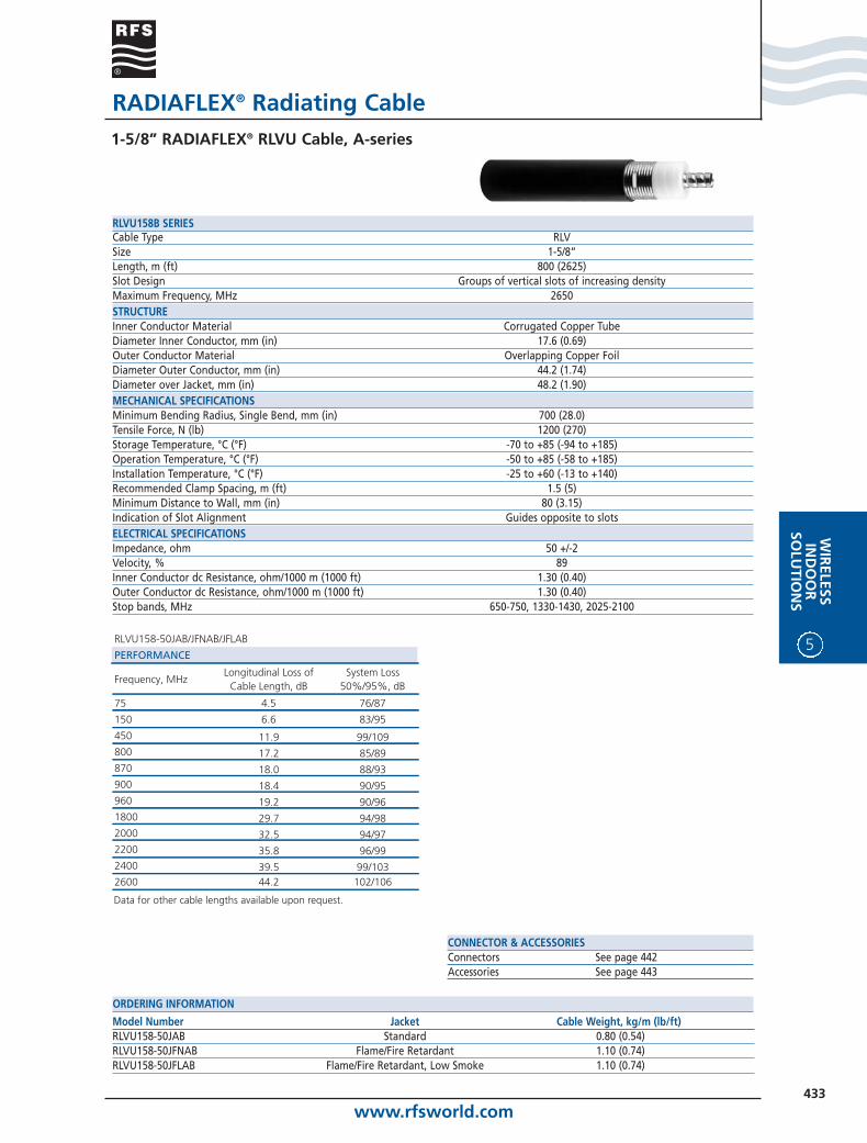
www.rfsworld.com433
WIR
ELESSIN
DO
OR
SOLU
TION
S
5
RADIAFLEX® Radiating Cable1-5/8” RADIAFLEX® RLVU Cable, A-series
CONNECTOR & ACCESSORIESConnectors See page 442Accessories See page 443
Model Number Jacket Cable Weight, kg/m (lb/ft)RLVU158-50JAB Standard 0.80 (0.54)RLVU158-50JFNAB Flame/Fire Retardant 1.10 (0.74)RLVU158-50JFLAB Flame/Fire Retardant, Low Smoke 1.10 (0.74)
ORDERING INFORMATION
Cable Type RLVSize 1-5/8”Length, m (ft) 800 (2625)Slot Design Groups of vertical slots of increasing densityMaximum Frequency, MHz 2650STRUCTUREInner Conductor Material Corrugated Copper TubeDiameter Inner Conductor, mm (in) 17.6 (0.69)Outer Conductor Material Overlapping Copper FoilDiameter Outer Conductor, mm (in) 44.2 (1.74)Diameter over Jacket, mm (in) 48.2 (1.90)MECHANICAL SPECIFICATIONSMinimum Bending Radius, Single Bend, mm (in) 700 (28.0)Tensile Force, N (lb) 1200 (270)Storage Temperature, °C (°F) -70 to +85 (-94 to +185)Operation Temperature, °C (°F) -50 to +85 (-58 to +185)Installation Temperature, °C (°F) -25 to +60 (-13 to +140)Recommended Clamp Spacing, m (ft) 1.5 (5)Minimum Distance to Wall, mm (in) 80 (3.15)Indication of Slot Alignment Guides opposite to slotsELECTRICAL SPECIFICATIONSImpedance, ohm 50 +/-2Velocity, % 89Inner Conductor dc Resistance, ohm/1000 m (1000 ft) 1.30 (0.40)Outer Conductor dc Resistance, ohm/1000 m (1000 ft) 1.30 (0.40)Stop bands, MHz 650-750, 1330-1430, 2025-2100
RLVU158B SERIES
RLVU158-50JAB/JFNAB/JFLAB
PERFORMANCE
Frequency, MHzLongitudinal Loss of
Cable Length, dBSystem Loss
50%/95%, dB
75 4.5 76/87
150 6.6 83/95
450 11.9 99/109800 17.2 85/89870 18.0 88/93900 18.4 90/95960 19.2 90/961800 29.7 94/982000 32.5 94/972200 35.8 96/992400 39.5 99/1032600 44.2 102/106
Data for other cable lengths available upon request.

www.rfsworld.com434
5
WIR
ELES
SIN
DO
OR
SOLU
TIO
NS
RADIAFLEX® Radiating Cable7/8” RADIAFLEX® RAY Cable, A-series
CONNECTOR & ACCESSORIESConnectors See page 442Accessories See page 443
Model Number Jacket Cable Weight, kg/m (lb/ft)RAY78-50JA Standard 0.45 (0.30)RAY78-50JFNA Flame/Fire Retardant 0.60 (0.40)RAY78-50JFLA Flame/Fire Retardant, Low Smoke 0.60 (0.40)
ORDERING INFORMATION
Cable Type RAYSize 7/8”Slot Design Groups of slope slots at short intervalsMaximum Frequency, MHz 1000STRUCTUREInner Conductor Material Copper TubeDiameter Inner Conductor, mm (in) 9.3 (0.37)Outer Conductor Material Overlapping Copper FoilDiameter Outer Conductor, mm (in) 23.8 (0.94)Diameter over Jacket, mm (in) 28.5 (1.12)MECHANICAL SPECIFICATIONSMinimum Bending Radius, Single Bend, mm (in) 350 (13.8)Tensile Force, N (lb) 2300 (507)Storage Temperature, °C (°F) -70 to +85 (-94 to +185)Operation Temperature, °C (°F) -50 to +85 (-58 to +185)Installation Temperature, °C (°F) -25 to +60 (-13 to +140)Recommended Clamp Spacing, m (ft) 0.9 (3)Minimum Distance to Wall, mm (in) 80 (3.15)Indication of Slot Alignment Bulge atop slotsELECTRICAL SPECIFICATIONSImpedance, ohm 50 +/-2Velocity, % 89Inner Conductor dc Resistance, ohm/1000 m (1000 ft) 1.46 (0.44)Outer Conductor dc Resistance, ohm/1000 m (1000 ft) 2.16 (0.66)Stop bands, MHz 240-300, 500-590, 750-860
RAY78 SERIES
RAY78-50JA/JFNA/JFLA
PERFORMANCE
Frequency, MHzLongitudinal Loss,
dB/100 m (dB/100 ft)Coupling Loss 50%/95%, dB
75 0.86 (0.26) 57/66150 1.32 (0.40) 62/73450 2.67 (0.81) 62/69870 5.41 (1.65) 56/65900 5.70 (1.74) 56/63
960 6.46 (1.97) 56/62

www.rfsworld.com435
WIR
ELESSIN
DO
OR
SOLU
TION
S
5
RADIAFLEX® Radiating Cable7/8” RADIAFLEX® RAY Cable, A-series
CONNECTOR & ACCESSORIESConnectors See page 442Accessories See page 443
Model Number Jacket Cable Weight, kg/m (lb/ft)RAY78-50JAB Standard 0.45 (0.30)RAY78-50JFNAB Flame/Fire Retardant 0.60 (0.40)RAY78-50JFLAB Flame/Fire Retardant, Low Smoke 0.60 (0.40)
ORDERING INFORMATION
Cable Type RAYSize 7/8”Slot Design Groups of slope slots at short intervalsMaximum Frequency, MHz 900STRUCTUREInner Conductor Material Copper TubeDiameter Inner Conductor, mm (in) 9.3 (0.37)Outer Conductor Material Overlapping Copper FoilDiameter Outer Conductor, mm (in) 23.8 (0.94)Diameter over Jacket, mm (in) 28.5 (1.12)MECHANICAL SPECIFICATIONSMinimum Bending Radius, Single Bend, mm (in) 350 (13.8)Tensile Force, N (lb) 2300 (507)Storage Temperature, °C (°F) -70 to +85 (-94 to +185)Operation Temperature, °C (°F) -50 to +85 (-58 to +185)Installation Temperature, °C (°F) -25 to +60 (-13 to +140)Recommended Clamp Spacing, m (ft) 0.9 (3)Minimum Distance to Wall, mm (in) 80 (3.15)Indication of Slot Alignment Bulge atop slotsELECTRICAL SPECIFICATIONSImpedance, ohm 50 +/-2Velocity, % 89Inner Conductor dc Resistance, ohm/1000 m (1000 ft) 1.46 (0.44)Outer Conductor dc Resistance, ohm/1000 m (1000 ft) 2.16 (0.66)Stop bands, MHz 285-350, 580-680
RAY78B SERIES
RAY78-50JAB/JFNAB/JFLAB
PERFORMANCE
Frequency, MHzLongitudinal Loss,
dB/100 m (dB/100 ft)Coupling Loss 50%/95%, dB
75 1.03 (0.31) 56/65150 1.45 (0.44) 64/76450 2.85 (0.87) 62/68800 5.00 (1.53) 60/68
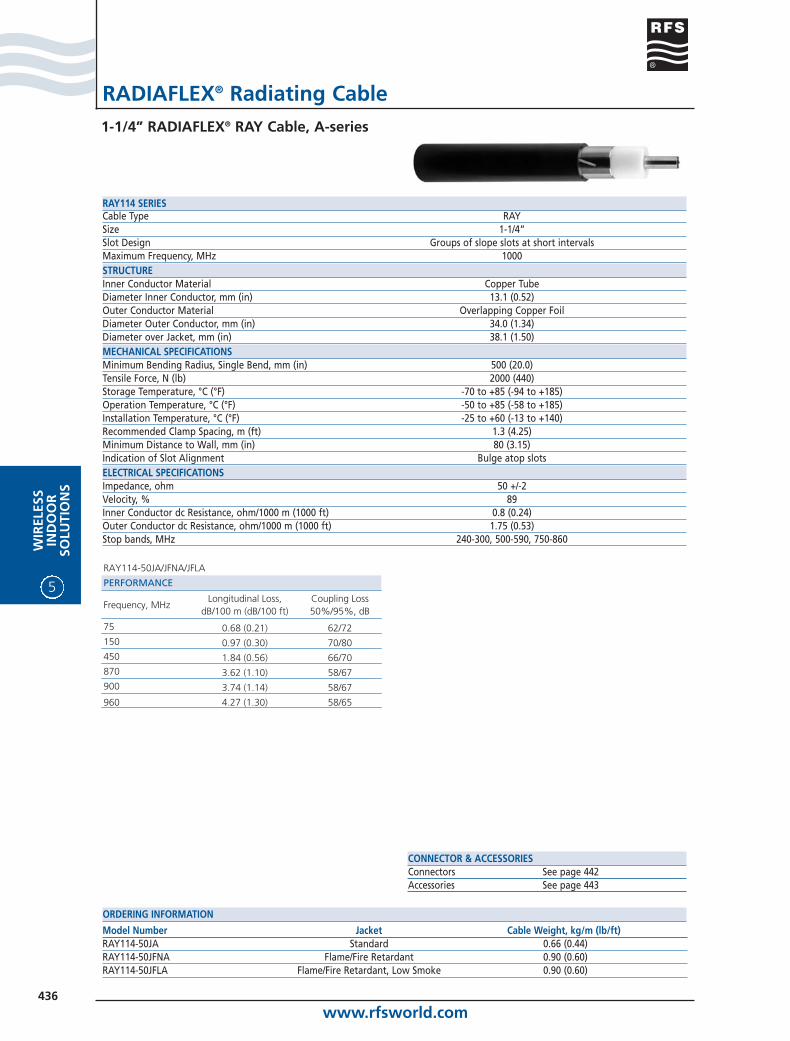
www.rfsworld.com436
5
WIR
ELES
SIN
DO
OR
SOLU
TIO
NS
RADIAFLEX® Radiating Cable1-1/4” RADIAFLEX® RAY Cable, A-series
CONNECTOR & ACCESSORIESConnectors See page 442Accessories See page 443
Model Number Jacket Cable Weight, kg/m (lb/ft)RAY114-50JA Standard 0.66 (0.44)RAY114-50JFNA Flame/Fire Retardant 0.90 (0.60)RAY114-50JFLA Flame/Fire Retardant, Low Smoke 0.90 (0.60)
ORDERING INFORMATION
Cable Type RAYSize 1-1/4”Slot Design Groups of slope slots at short intervalsMaximum Frequency, MHz 1000STRUCTUREInner Conductor Material Copper TubeDiameter Inner Conductor, mm (in) 13.1 (0.52)Outer Conductor Material Overlapping Copper FoilDiameter Outer Conductor, mm (in) 34.0 (1.34)Diameter over Jacket, mm (in) 38.1 (1.50)MECHANICAL SPECIFICATIONSMinimum Bending Radius, Single Bend, mm (in) 500 (20.0)Tensile Force, N (lb) 2000 (440)Storage Temperature, °C (°F) -70 to +85 (-94 to +185)Operation Temperature, °C (°F) -50 to +85 (-58 to +185)Installation Temperature, °C (°F) -25 to +60 (-13 to +140)Recommended Clamp Spacing, m (ft) 1.3 (4.25)Minimum Distance to Wall, mm (in) 80 (3.15)Indication of Slot Alignment Bulge atop slotsELECTRICAL SPECIFICATIONSImpedance, ohm 50 +/-2Velocity, % 89Inner Conductor dc Resistance, ohm/1000 m (1000 ft) 0.8 (0.24)Outer Conductor dc Resistance, ohm/1000 m (1000 ft) 1.75 (0.53)Stop bands, MHz 240-300, 500-590, 750-860
RAY114 SERIES
RAY114-50JA/JFNA/JFLA
PERFORMANCE
Frequency, MHzLongitudinal Loss,
dB/100 m (dB/100 ft)Coupling Loss 50%/95%, dB
75 0.68 (0.21) 62/72150 0.97 (0.30) 70/80450 1.84 (0.56) 66/70870 3.62 (1.10) 58/67900 3.74 (1.14) 58/67
960 4.27 (1.30) 58/65
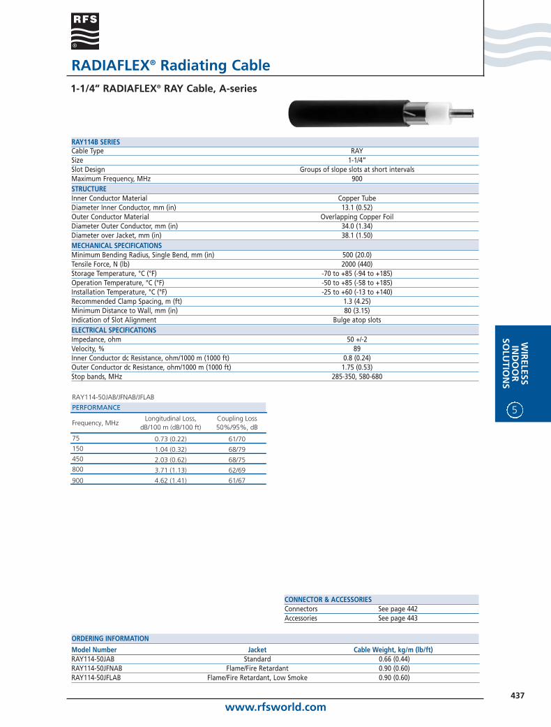
www.rfsworld.com437
WIR
ELESSIN
DO
OR
SOLU
TION
S
5
RADIAFLEX® Radiating Cable1-1/4” RADIAFLEX® RAY Cable, A-series
CONNECTOR & ACCESSORIESConnectors See page 442Accessories See page 443
Model Number Jacket Cable Weight, kg/m (lb/ft)RAY114-50JAB Standard 0.66 (0.44)RAY114-50JFNAB Flame/Fire Retardant 0.90 (0.60)RAY114-50JFLAB Flame/Fire Retardant, Low Smoke 0.90 (0.60)
ORDERING INFORMATION
Cable Type RAYSize 1-1/4”Slot Design Groups of slope slots at short intervalsMaximum Frequency, MHz 900STRUCTUREInner Conductor Material Copper TubeDiameter Inner Conductor, mm (in) 13.1 (0.52)Outer Conductor Material Overlapping Copper FoilDiameter Outer Conductor, mm (in) 34.0 (1.34)Diameter over Jacket, mm (in) 38.1 (1.50)MECHANICAL SPECIFICATIONSMinimum Bending Radius, Single Bend, mm (in) 500 (20.0)Tensile Force, N (lb) 2000 (440)Storage Temperature, °C (°F) -70 to +85 (-94 to +185)Operation Temperature, °C (°F) -50 to +85 (-58 to +185)Installation Temperature, °C (°F) -25 to +60 (-13 to +140)Recommended Clamp Spacing, m (ft) 1.3 (4.25)Minimum Distance to Wall, mm (in) 80 (3.15)Indication of Slot Alignment Bulge atop slotsELECTRICAL SPECIFICATIONSImpedance, ohm 50 +/-2Velocity, % 89Inner Conductor dc Resistance, ohm/1000 m (1000 ft) 0.8 (0.24)Outer Conductor dc Resistance, ohm/1000 m (1000 ft) 1.75 (0.53)Stop bands, MHz 285-350, 580-680
RAY114B SERIES
RAY114-50JAB/JFNAB/JFLAB
PERFORMANCE
Frequency, MHzLongitudinal Loss,
dB/100 m (dB/100 ft)Coupling Loss 50%/95%, dB
75 0.73 (0.22) 61/70150 1.04 (0.32) 68/79450 2.03 (0.62) 68/75800 3.71 (1.13) 62/69
900 4.62 (1.41) 61/67

www.rfsworld.com438
5
WIR
ELES
SIN
DO
OR
SOLU
TIO
NS
RADIAFLEX® Radiating Cable1-5/8” RADIAFLEX® RAY Cable, A-series
CONNECTOR & ACCESSORIESConnectors See page 442Accessories See page 443
Model Number Jacket Cable Weight, kg/m (lb/ft)RAY158-50JA Standard 0.80 (0.54)RAY158-50JFNA Flame/Fire Retardant 1.10 (0.74)RAY158-50JFLA Flame/Fire Retardant, Low Smoke 1.10 (0.74)
ORDERING INFORMATION
Cable Type RAYSize 1-5/8”Slot Design Groups of slope slots at short intervalsMaximum Frequency, MHz 1000STRUCTUREInner Conductor Material Corrugated Copper TubeDiameter Inner Conductor, mm (in) 17.6 (0.69)Outer Conductor Material Overlapping Copper FoilDiameter Outer Conductor, mm (in) 44.2 (1.74)Diameter over Jacket, mm (in) 48.2 (1.90)MECHANICAL SPECIFICATIONSMinimum Bending Radius, Single Bend, mm (in) 700 (28.0)Tensile Force, N (lb) 1200 (270)Storage Temperature, °C (°F) -70 to +85 (-94 to +185)Operation Temperature, °C (°F) -50 to +85 (-58 to +185)Installation Temperature, °C (°F) -25 to +60 (-13 to +140)Recommended Clamp Spacing, m (ft) 1.5 (5)Minimum Distance to Wall, mm (in) 80 (3.15)Indication of Slot Alignment Guides opposite to slotsELECTRICAL SPECIFICATIONSImpedance, ohm 50 +/-2Velocity, % 89Inner Conductor dc Resistance, ohm/1000 m (1000 ft) 1.30 (0.40)Outer Conductor dc Resistance, ohm/1000 m (1000 ft) 1.30 (0.40)Stop bands, MHz 240-300, 500-590, 750-860
RAY158 SERIES
RAY158-50JA/JFNA/JFLA
PERFORMANCE
Frequency, MHzLongitudinal Loss,
dB/100 m (dB/100 ft)Coupling Loss 50%/95%, dB
75 0.56 (0.17) 65/75150 0.78 (0.24) 72/83450 1.49 (0.45) 67/72870 2.85 (0.87) 60/66900 2.92 (0.89) 60/66
960 3.38 (1.03) 60/66
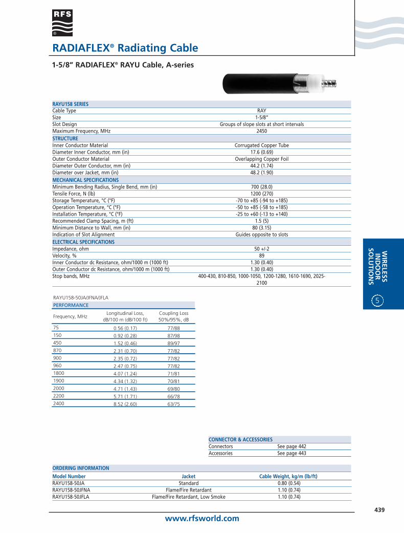
www.rfsworld.com439
WIR
ELESSIN
DO
OR
SOLU
TION
S
5
RADIAFLEX® Radiating Cable1-5/8” RADIAFLEX® RAYU Cable, A-series
CONNECTOR & ACCESSORIESConnectors See page 442Accessories See page 443
Model Number Jacket Cable Weight, kg/m (lb/ft)RAYU158-50JA Standard 0.80 (0.54)RAYU158-50JFNA Flame/Fire Retardant 1.10 (0.74)RAYU158-50JFLA Flame/Fire Retardant, Low Smoke 1.10 (0.74)
ORDERING INFORMATION
Cable Type RAYSize 1-5/8”Slot Design Groups of slope slots at short intervalsMaximum Frequency, MHz 2450STRUCTUREInner Conductor Material Corrugated Copper TubeDiameter Inner Conductor, mm (in) 17.6 (0.69)Outer Conductor Material Overlapping Copper FoilDiameter Outer Conductor, mm (in) 44.2 (1.74)Diameter over Jacket, mm (in) 48.2 (1.90)MECHANICAL SPECIFICATIONSMinimum Bending Radius, Single Bend, mm (in) 700 (28.0)Tensile Force, N (lb) 1200 (270)Storage Temperature, °C (°F) -70 to +85 (-94 to +185)Operation Temperature, °C (°F) -50 to +85 (-58 to +185)Installation Temperature, °C (°F) -25 to +60 (-13 to +140)Recommended Clamp Spacing, m (ft) 1.5 (5)Minimum Distance to Wall, mm (in) 80 (3.15)Indication of Slot Alignment Guides opposite to slotsELECTRICAL SPECIFICATIONSImpedance, ohm 50 +/-2Velocity, % 89Inner Conductor dc Resistance, ohm/1000 m (1000 ft) 1.30 (0.40)Outer Conductor dc Resistance, ohm/1000 m (1000 ft) 1.30 (0.40)Stop bands, MHz 400-430, 810-850, 1000-1050, 1200-1280, 1610-1690, 2025-
2100
RAYU158 SERIES
RAYU158-50JA/JFNA/JFLA
PERFORMANCE
Frequency, MHzLongitudinal Loss,
dB/100 m (dB/100 ft)Coupling Loss 50%/95%, dB
75 0.56 (0.17) 77/88150 0.92 (0.28) 87/98450 1.52 (0.46) 89/97870 2.31 (0.70) 77/82900 2.35 (0.72) 77/82960 2.47 (0.75) 77/821800 4.07 (1.24) 71/811900 4.34 (1.32) 70/812000 4.71 (1.43) 69/802200 5.71 (1.71) 66/782400 8.52 (2.60) 63/75

www.rfsworld.com440
5
WIR
ELES
SIN
DO
OR
SOLU
TIO
NS
RADIAFLEX® Radiating Cable1-5/8” RADIAFLEX® RAYU Cable, A-series
CONNECTOR & ACCESSORIESConnectors See page 442Accessories See page 443
Model Number Jacket Cable Weight, kg/m (lb/ft)RAYU158-50JAT Standard 0.80 (0.54)RAYU158-50JFNAT Flame/Fire Retardant 1.10 (0.74)RAYU158-50JFLAT Flame/Fire Retardant, Low Smoke 1.10 (0.74)
ORDERING INFORMATION
Cable Type RAYSize 1-5/8”Slot Design Groups of slope slots at short intervalsMaximum Frequency, MHz 2200STRUCTUREInner Conductor Material Corrugated Copper TubeDiameter Inner Conductor, mm (in) 17.6 (0.69)Outer Conductor Material Overlapping Copper FoilDiameter Outer Conductor, mm (in) 44.2 (1.74)Diameter over Jacket, mm (in) 48.2 (1.90)MECHANICAL SPECIFICATIONSMinimum Bending Radius, Single Bend, mm (in) 700 (28.0)Tensile Force, N (lb) 1200 (270)Storage Temperature, °C (°F) -70 to +85 (-94 to +185)Operation Temperature, °C (°F) -50 to +85 (-58 to +185)Installation Temperature, °C (°F) -25 to +60 (-13 to +140)Recommended Clamp Spacing, m (ft) 1.5 (5)Minimum Distance to Wall, mm (in) 80 (3.15)Indication of Slot Alignment Guides opposite to slotsELECTRICAL SPECIFICATIONSImpedance, ohm 50 +/-2Velocity, % 89Inner Conductor dc Resistance, ohm/1000 m (1000 ft) 1.30 (0.40)Outer Conductor dc Resistance, ohm/1000 m (1000 ft) 1.30 (0.40)Stop bands, MHz 1000-1650
RAYU158T SERIES
RAYU158-50JAT/JFNAT/JFLAT
PERFORMANCE
Frequency, MHzLongitudinal Loss,
dB/100 m (dB/100 ft)Coupling Loss 50%/95%, dB
800 2.12 (0.65) 65/69900 2.47 (0.75) 60/641800 4.60 (1.40) 57/601900 4.13 (1.26) 60/632000 3.90 (1.19) 63/662200 4.10 (1.25) 63/68