Embed Size (px)
Citation preview
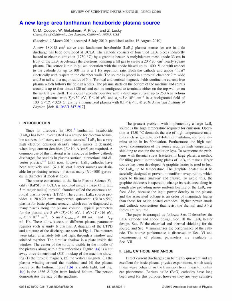
A new large area lanthanum hexaboride plasma sourceC. M. Cooper, W. Gekelman, P. Pribyl, and Z. LuckyUniversity of California, Los Angeles, California 90095, USA
�Received 9 March 2010; accepted 5 July 2010; published online 16 August 2010�
A new 18�18 cm2 active area lanthanum hexaboride �LaB6� plasma source for use in a dcdischarge has been developed at UCLA. The cathode consists of four tiled LaB6 pieces indirectlyheated to electron emission �1750 °C� by a graphite heater. A molybdenum mesh anode 33 cm infront of the LaB6 accelerates the electrons, ionizing a fill gas to create a 20�20 cm2 nearly squareplasma. The source is run in pulsed operation with the anode biased up to +400 V dc with respectto the cathode for up to 100 ms at a 1 Hz repetition rate. Both the cathode and anode “float”electrically with respect to the chamber walls. The source is placed in a toroidal chamber 2 m wideand 3 m tall with a major radius of 5 m. Toroidal and vertical magnetic fields confine the current-freeplasma which follows the field in a helix. The plasma starts on the bottom of the machine and spiralsaround it up to four times �120 m� and can be configured to terminate either on the top wall or onthe neutral gas itself. The source typically operates with a discharge current up to 250 A in heliummaking plasmas with Te�30 eV, Ti�16 eV, and ne�3�1013 cm−3 in a background field of100 G�Bo�320 G, giving a magnetized plasma with 0.1���1. © 2010 American Institute ofPhysics. �doi:10.1063/1.3471917�
I. INTRODUCTION
Since its discovery in 1951,1 lanthanum hexaboride�LaB6� has been investigated as a source for electron beams,ion sources, ion lasers, and plasma sources.2 LaB6 has a veryhigh electron emission density which makes it desirablewhen large current densities �J�10 A /cm2� are required. Acommon use of this material is as a source in hollow cathodedischarges for studies in plasma surface interactions and di-verter physics.3–5 Until now, however, LaB6 cathodes havebeen relatively small �R�10 cm�. Larger sources are desir-able for producing research plasmas many �N�100� gyrora-dii in diameter at modest fields.
The source constructed at the Basic Plasma Science Fa-cility �BaPSF� at UCLA is mounted inside a large �3 m tall,5 m major radius� toroidal chamber called the enormous to-roidal plasma device �ETPD�. The current LaB6 source pro-vides a 20�20 cm2 magnetized quiescent ��n /n�5%�plasma for basic plasma research which can be diagnosed atmany places along the plasma column. Typical parametersfor the plasma are 5 eV�Te�30 eV, 1 eV�Ti�16 eV,ne�3�1013 m−3, 5 ms��discharge�100 ms, and f rep
=1 Hz. These allow access to different plasma parameterregimes such as unity � plasmas. A diagram of the ETPDand a picture of the discharge are seen in Fig. 1. The pictureswere taken alternately left and right through a window andstitched together. The circular shadow is a plate inside thewindow. The center of the torus is visible in the middle ofthe pictures along with a few reflections. Figure 1�a� is a cutaway three-dimensional �3D� mockup of the machine show-ing �1� the toroidal magnets, �2� the vertical magnets, �3� theplasma winding around the machine, and �4� the plasmasource on the bottom. Figure 1�b� is visible light, and Fig.1�c� is the 4686 Å light from ionized helium. The persondemonstrates the size of the machine.
The greatest problem with implementing a large LaB6
source is the high temperature required for emission. Opera-tion at 1750 °C demands the use of high temperature mate-rials such as graphite, molybdenum, tantalum, and pure alu-mina oxide in its fabrication. Furthermore, the high totalpower consumption of the source requires high temperatureshielding to contain the radiation loss. To overcome the prob-lems with thermal stress fractures in large plates, a methodfor tiling precut interlocking plates of LaB6 to make a largersource has been developed. A graphite heater is used to heatthe LaB6 up to temperature. The graphite heater must becarefully designed to prevent nonuniform evaporation, whichleads to thermal runaway and failure. To avoid this, thegraphite thickness is tapered to change its resistance along itslength also providing more uniform heating of the LaB6 sur-face. Also, because the input power density to the plasmaand the associated voltage is an order of magnitude higherthan those for oxide coated cathodes,1 higher power anodeand cathode connections that resist the thermal and J�Bforces are required.
The paper is arranged as follows: Sec. II describes theLaB6 cathode and anode design, Sec. III the LaB6 heaterdesign, Sec. IV the electrical and thermal shielding for thesource, and Sec. V summarizes the performance of the cath-ode. The source performance is discussed in Sec. VI andmeasurements of plasma parameters are available inSec. VII.
II. LaB6 CATHODE AND ANODE
Direct current discharges can be highly quiescent and areexcellent for basic plasma physics experiments, which studylinear wave behavior or the transition from linear to nonlin-ear phenomena. Barium oxide �BaO� cathodes have longbeen used for this purpose; however they are very sensitive
REVIEW OF SCIENTIFIC INSTRUMENTS 81, 083503 �2010�
0034-6748/2010/81�8�/083503/8/$30.00 © 2010 American Institute of Physics81, 083503-1

to poisoning by oxygen and other electronegative com-pounds and get sputtered away by ion bombardment. LaB6,on the other hand, can be exposed to air and water leaks andstill be reused.2 It does not have to be recoated when themachine is open to air as do oxide coated cathodes. Thematerial can withstand the higher ion fluxes associated withhigher current discharges. Although LaB6 must be heated tonearly twice as hot as BaO, it has a higher electron emissionper unit area and therefore can produce higher plasma den-sities and temperatures than oxide coated cathodes.6 Figure 2shows a diagram of the LaB6 plasma source. Electrons areboiled off the LaB6 in the center and accelerated through theanode toward the bottom of the page. Shields are placedaround the source and its infrastructure to protect it from theplasma.
Single LaB6 crystals are limited to a few millimeters insize.7 To make a large area cathode, plates of sintered LaB6
powder must be used. Various sizes of LaB6 plates are avail-able from companies such as Cerac.8 The increase in LaB6
size comes with a reduction in LaB6 durability. Large LaB6
pieces are subject to thermal stress when they are heated andfrequently fracture. Although a few cracks in LaB6 do notaffect the plasma produced, compound fracturing of theplates leads to isolated islands in the LaB6, rendering it use-less. Nonuniformities in the cathode temperature producenonuniformities in the plasma. Initial designs with a singlelarge �20 cm square� piece compound fractured after only amonth of use.
To mitigate fracturing, a 20.3�20.3�0.47 cm3 �8.01�8.01�3 /16 in.3� LaB6 plate is cut into four equally sized10.1�10.1 cm2 tiles. This greatly reduces the occurrence offracturing. Each tile now only has a simple increasing ther-mal gradient from a warm outside to a hot inside and the tilecan properly expand in both directions. In a large single tileformat, the edges tend to be cooler than the center. Thermalexpansion stresses in the single tile are greater and it is morelikely to crack since the center expands more than the out-side. The precut LaB6 tiles have recorded over 350 h of“plasma on” time without any cracking. Tiles that are heatedup and cooled down over hours can be reused without prob-lems. Tiles that are abruptly thermally cycled due to powersupply failure have a higher chance of fracturing.
The tiles are cut from a single piece of 99.5% pure sin-tered LaB6. A 21.7° vertical angled bevel cut with respect tothe normal centered on the plate is used to make the verticalseam. This gave enough overlap with the adjacent tile tonever expose the heater while uniformly heating the tiles.The horizontal cut is more difficult, as a similar angled bevelcut would cause plates to slide past one another. To preventthis, a beveled tongue and groove seam is used as the inter-face between the vertical plates. The tongue is on the toptiles, 1.27 mm tall, and centered on the plate’s depth. Thegroove on the bottom tile matched the tongue above it. Thedimensions for the seams were selected to be as deep aspossible while maintaining a constant surface temperature.Most importantly, there are no measurable nonuniformities inthe plasma from any of the cuts in the LaB6. All of the cutswere done with electrical discharge machining �EDM�. Anexploded closeup of the cuts is in Fig. 3.
The LaB6 tiles are held in a graphite frame cut 2.5 mmlarger than the tiles on all sides to account for the differentialthermal expansion between LaB6 and graphite. Since thisamount of LaB6 at 1750 °C expands 3.3 mm �Ref. 9� while
FIG. 1. �Color� �a� A schematic of the ETPD. �b� Visible light photographand �c� 4686 Å helium light photograph for a discharge of 400 V in 2 mTorrof helium. The plasma source is in the lower left and spirals around fourtimes to the upper right.
FIG. 2. �Color online� A diagram of the LaB6 plasma source.
FIG. 3. A closeup of the two cuts dividing the LaB6 plate into four tiles.
083503-2 Cooper et al. Rev. Sci. Instrum. 81, 083503 �2010�

the cooler TRA-1 Poco graphite frame at 1400 °C expands2.3 mm,10 high temperature electrically conducting springsare required to deliver cathode power. The 2.5 mm outsidegap is filled with two overlapping layers of 0.25 mm thickcorrugated tantalum strips that provide a flexible, springlikeconductive connection to the sides of the LaB6 tiles. In ad-dition, six graphite holding tabs are placed around the backedges of the LaB6 to secure the tiles against the front lip inthe frame. Since the tantalum in contact with LaB6 tends tobecome embrittled at high temperatures, the tantalum springsaround the LaB6 are replaced every time the source is rebuilt.The tiles and screen are placed against a small 1.3 cm lip onthe front of the frame to prevent them from falling out. Thisyields the actual emission size of 18�18 cm2 with the ac-tual measured width of the plasma being 20�20 cm2. Anassembled view is available in Fig. 4. This is the back of thecathode facing the heater. An exploded view is available inFig. 5, showing the assembly of the cathode with the graph-ite holding tabs. It is assembled from the back against thegraphite lip shown in both pictures.
A problem with thin LaB6 cathodes is the evaporationand sputtering of material due to ion bombardment. How-ever, given the thickness of the plates used here, evaporationof the LaB6 is not an issue and is on the contrary welcomed.High power ��150 V, �6 A /cm2� discharges of argonplasma are routinely used to clean the surface of the LaB6. Afew days of cleaning every few weeks are useful to maintainplasma parameters.
The anode is a 35�55 cm2 piece of 70% transparentmolybdenum mesh embedded in a water-cooled steel frame.
The anode is 0.33–1.6 m away from the cathode. All of thedata measured in this paper were done with the anode 0.33 maway from the cathode.
The plasma is run in a pulsed dc configuration where thebias is applied for up to 100 ms at a 1 Hz repetition rate. Amodular high-power solid-state switch rated to 4 kA at 600 Vsimilar to one already in use on a BaO source11 is used toturn the plasma on and off.
III. CATHODE HEATER
The LaB6 cathode is indirectly heated to emission tem-perature by a graphite heater. Uniform heating is importantsince nonuniformities in the cathode temperature produce lo-cal variation in the plasma density. Graphite was chosen be-cause of its high melting point �3700 °C� and its ability tomaintain its structural integrity at high temperatures. Also,for a desired resistance and length, a larger cross section isrequired giving the heater greater structural strength, an ad-vantage over using most metals.
It was found that a heater power density of 100 W forevery square centimeter of emitting LaB6 is a good rule ofthumb for the minimum power needed to heat the surface ofthe LaB6 to emission. This power density was found to benearly similar for several LaB6 cathodes constructed withareas of 180–466 cm2. However, since LaB6 has a very non-linear electron emission density with temperature, a higherpower density would greatly improve the source perfor-mance. In this case, the LaB6 temperature and thereforeheater power was sought to be as high as possible. Sincemuch of the emitted heat of the heater is not directly incidenton the LaB6, careful attention was made to reflecting asmuch of the power back onto the LaB6 as possible. Thedetails of this are included in the following section.
The resistance of the heater was chosen to have the high-est current and lowest voltage possible to lower the chancesof arcing from the heater to the cathode or machine. How-ever, the current must be low enough to be easily transportedthrough vacuum feedthroughs and conductors in the vacuumsystem immersed in a magnetic field. The heater was de-signed to have a resistance of 0.2 � with heater power of45 kW �95 V at 475 A� at emission temperature. Since theresistance of graphite decreases with temperature, the de-signed resistance of the cold graphite heater is 0.33 �.
Another source of LaB6 heating is the self-heating due tothe plasma discharge power. During plasma production, ionsare accelerated toward the LaB6 surface and deposit theirenergy directly onto the surface of the LaB6. The instanta-neous power P= IdischVdisch may be high but the averagepower deposited is lowered by a factor of the duty cycle ofthe discharge, 100 ms every second which equals 10%. Foran average 150 A discharge at 400 V, the instantaneouspower is an additional 60 kW of heating power while theplasma is on, but the average power from shot to shot is only6 kW. The further heating increases emission and power out-put, therefore further increasing the self-heating. This feed-back cycle creates an equilibration time of up to an hourwhen changing parameters.
The heater shape is a snaked element cut by EDM out of
FIG. 4. �Color online� An assembled view of the cathode with one of theLaB6 tiles missing to show the corrugated Ta strips and the graphite framewith lip.
FIG. 5. �Color online� An exploded view of the cathode assembly.
083503-3 Cooper et al. Rev. Sci. Instrum. 81, 083503 �2010�

a solid plate of 30�30�2.03 cm3 TRA-1 graphite fromPoco Graphite10 as shown in Fig. 6. The heater element areais a square shape 20 cm on a side. The legs of the heater are7.9 mm wide with a leg to leg spacing of 0.625 cm. The fivelegs and two turns closest to the center of the heater werekept 2.0 cm thick with the rest of the heater machined downto 1.78 cm thick. On either side of the element is a 5.7 cmwide 1.78 cm thick tab that connects to the heater powerfeeds. The heater power feeds are 1.91�5.7 cm2 slabs ofgraphite that extend from the heater to the support frameoutside. Graphite was chosen for the power feeds as wellbecause it is in direct contact with the heater and needs toconduct electricity while providing some thermal isolation.The far ends of the heater power feeds are cool enough to beconnected to a water-cooled copper buss bar. Tantalum finsrise out of the heater power feeds to reflect heat back towardthe source and protect the copper buss bar.
The heater-cathode spacing was selected to be as smallas possible to maximize radiant heat flux but large enough toprevent cathode-heater arcing. A distance of 2.5 cm wasfound to work best.
IV. SHIELDING
Proper shielding of the plasma source to protect it fromexternal plasma arcs is critical to its longevity. Also, becauseLaB6 emission scales nonlinearly with temperature, it is ofutmost importance to reflect most of the heat at the cathodeand not radiate it out of the sides and back of the structure.Proper high temperature ��1750 °C� radiation shielding iscritical for good LaB6 emission. At least three layers of high-temperature shielding are used between the heater and anynonhigh-temperature material. The shielding consists of twoparts: molybdenum and tantalum sheets for high temperaturelow load shielding �reflectors� and graphite plates for hightemperature high load shielding �walls�. In addition, a water-cooled copper shroud covered with 3.2 mm thick floatinggraphite plates for protection sits on the inside walls of thedevice. It protects the machine walls, the power feeds, andpersonnel that could touch the outside.
The first shield has direct line of sight to the heater andis the most important reflector. On the back of the heater arefour 30 cm�30 cm�3.2 mm TRA-1 graphite platesspaced 6.4 mm apart. A thin sheet of 30�30 cm2, 0.12 mm�0.005 in.� molybdenum is between the first and secondclosest plates. Molybdenum was chosen because of its highreflection coefficient for radiation at the operating tempera-
ture. Surrounding the heater on all sides are 9.5 mm thickgraphite walls. Mounted on the heater facing side of eachwall are two layers of 0.12 mm �0.005 in.� tantalum that arespaced 3.2 and 6.4 mm from the wall. The pieces are taperedto reflect heat forward toward the cathode. A third tantalumlayer surrounds the outside of the graphite wall. The shields,power feeds, and support structure are all electrically isolatedand mounted on a steel frame inside the vacuum vessel.Electrically isolated graphite plates are mounted over thefront sides of the source to protect it from plasma arcing �seeFig. 2�. The entire source sits inside a housing made of float-ing graphite plates which contain the heat and prevents arc-ing out the backs or sides of the source �not shown�.
V. LaB6 CATHODE PERFORMANCE
The function of the LaB6 source is to provide a source ofhigh energy electrons to produce plasma on the current freeside of the anode. Changing the machine parameters affectsthe plasma as well as the source making the plasma. Sincethe source is run in constant voltage mode, the parameter thatchanges is the discharge current. What follows is a briefsummary of the LaB6 performance which is entirely obser-vational. A more thorough description of hot emissive cath-ode models is available in the literature.12
The LaB6 surface temperature was measured using anOmegascope OS3750 optical pyrometer pointed at the sur-face. Keeping all other parameters the same, an increase inheater power and LaB6 temperature was always accompa-nied by a nonlinear increase in discharge current. Along withthe self-heating effects, this indicates that the source is oper-ated in a regime where thermal emission is still important.Although the predicted current density is higher than themeasured current density in helium, several other factors goin to determining the discharge current achieved. For ex-ample, a 15 ms discharge at 150 V in 1 mTorr of argon witha background field of 320 G yielded a discharge current of2.2 kA �6.8 A /cm2�, near the predicted current density forLaB6 at this temperature. However, the same parameters with1 mTorr of helium yielded a discharge current of only 25 A�0.08 A /cm2�. Only by raising the background pressure anddischarge voltage were higher discharge currents obtained atthis anode-cathode spacing of 0.33 m. Increasing the anode-cathode spacing to 1.6 m yielded higher discharge currents inhelium, over 1.4 kA �4.3 A /cm2�, but the inhibited use athigher discharge voltages ��250 V� due to overheating ofthe anode and arcing and was not used.
At a given discharge voltage, the discharge current wasfound to increase with an increase in background field whenkeeping the pitch angle constant by increasing the verticalfield. A similar 10 cm diameter LaB6 cathode was bench-marked in the large plasma device �LAPD� for varying mag-netic fields and found that raising the field from 300 to 600 Gcorresponded to 30% increase in the discharge current and afactor of 2 in plasma density at the same voltage. This maybe due to space charge effects relating to the significantlyincreased confinement from the ions going from unmagne-tized �Rp /i�1.5 for 10 eV ion� to weakly magnetized�Rp /i�3.7 for 10 eV ion� plasma, which should also hap-
FIG. 6. �Color online� Schematic of the cathode heater and shielding assem-bly. The LaB6 cathode �not pictured� mounts above the heater and is at-tached to the tantalum covered walls.
083503-4 Cooper et al. Rev. Sci. Instrum. 81, 083503 �2010�
pen on the scale of this larger cathode. The increase taperedoff at 600 G and was tested up to 1250 G without any furtherincrease in discharge current. Also, the current density goesto zero as Bo goes to zero. In the ETPD, the current toroidalfield of 320 G is set by the available power supply.
VI. DISCUSSION OF LaB6 PLASMA
The scope of this paper is to describe and benchmark theplasma created by the cathode which is the actual tool to beused in future basic plasma physics experiments. In the fol-lowing section, the “plasma produced by the LaB6” refers tothe plasma that extends up to 120 m past the anode and iscurrent-free, highly quiescent, and extremely repeatable. Theonly source of heat and momentum into this region of theplasma is the electrons from the cathode and some plasmathat streams through the 70% transparent anode and ionize orthermalize on the flow free plasma side. None of the datawere collected in the 33 cm region of current driven plasmabetween the anode and the cathode. It is clear that the finalplasma parameters are not determined solely by the electronsand plasma coming from the source region, but by radial andaxial transport of particles and heat inside the plasma.13
The pitch angle of the plasma column can be adjusted byvarying the vertical field with the typical value being 1.4°�6 G� which corresponds to the plasma rising 75 cm for each31.4 m revolution around the machine. Varying the pitchangle up to 5° was found to have no effect on dischargecurrent or plasma parameters and the plasma is never run ina mode where it overlaps itself; it is always distinct rings.The typical vertical ring spacing is 55 cm ��25 ion gyroradiiand approximately six times the plasma radius� with theplasma density dropping below a measurable amount be-tween rings. In addition, the plasma is current free to firstorder so no J�B force between adjacent rings is expected orobserved. The plasma can be modeled as a single long con-tinuous uniformly curved cylinder with no periodicity in theboundary conditions. This uniqueness makes the plasma ex-cellent for studying long parallel phenomena such as trans-port and parallel wave dampening.
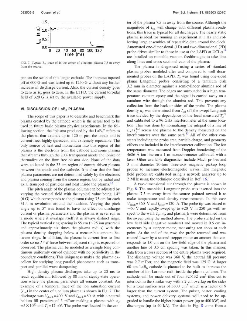
High density plasma discharges take up to 20 ms toreach equilibrium, followed by 80 ms of steady-state opera-tion where the plasma parameters all remain constant. Anexample of a temporal trace of the ion saturation current�Isat� in the center of a helium plasma is shown in Fig. 7. Thedischarge was Vdisch=400 V and Idisch=80 A with a neutralhelium fill pressure of 3 mTorr making a plasma with ne
=5�1012 and Te=12 eV. The probe was located in the cen-
ter of the plasma 7.5 m away from the source. Although themagnitude of Isat will change with different plasma condi-tions, this trace is typical for all discharges. The nearly staticplasma is ideal for running an experiment at 1 Hz and col-lecting large ensembles of repeatable data around the clock.Automated one-dimensional �1D� and two-dimensional �2D�probe drives similar to those in use at the LAPD at UCLA14
are installed on rotatable vacuum feedthroughs to take dataalong lines and cross sectional cuts of the plasma.
The plasma is diagnosed using a series of standardplasma probes modeled after and compared to well docu-mented probes on the LAPD. Te was found using one-sidedplanar Langmuir probes consisting of a tantalum disk3.2 mm in diameter against a semicylinder alumina rod ofthe same diameter. The edges are surrounded in a high tem-perature vacuum epoxy and the signal is carried away on atantalum wire through the alumina rod. This prevents anycollection from the back or sides of the probe. The plasmadensity ne was determined from Isat off the swept Langmuirtrace divided by the dependence of the local measured Te
1/2
and calibrated to a 96 GHz interferometer at the same loca-tion. This was done by normalizing the integral of a line ofIsat /Te
1/2 across the plasma to the density measured on theinterferometer over the same path.15 All of the other con-stants including the probe area, particle charge, and geometryeffects are included in the interferometer calibration. The iontemperature was measured from Doppler broadening of the4686 Å ion line on a 1 m monochrometer calibrated with alaser. Other available diagnostics include Mach probes and3 mm diameter 20-turn three-axis magnetic pickup loopprobes to measure electromagnetic waves. The magneticfield probes are calibrated using a network analyzer up to2 MHz using the technique described in Ref. 16.
A two-dimensional cut through the plasma is shown inFig. 8. The one-sided Langmuir probe was inserted into theplasma 7.5 m away from the source pointed toward it tomake temperature and density measurements. In this caseVdisch=360 V and Idisch=120 A. The probe tip was biased to60 V and rapidly swept up to +20 V in 250 �s with re-spect to the wall. Te, ne, and plasma � were determined fromthe sweep using the method above. The probe started on thelow field side �negative numbers� and moved in 0.5 cm in-crements by a stepper motor, measuring ten shots at eachpoint. At the end of the row, the probe returned and wasrotated lower by a second stepper motor an amount that cor-responds to 1.0 cm on the low field edge of the plasma andanother line of 0.5 cm spacing was taken. In this manner,data from a cross section of the entire plasma were acquired.The discharge voltage was 360 V, the neutral fill pressurewas 2.7 mTorr, and the magnetic field was 125 G. A larger60 cm LaB6 cathode is planned to be built to increase thenumber of ion Larmour radii inside the plasma column. Thecathode will be made out of four 32�32 cm2 tiles cut tointerlock in the similar way with a 2 cm overlap on the sidesfor a total surface area of 3600 cm2 which is a factor of 9larger than the current system. The pulser, heater, coolingsystems, and power delivery systems will need to be up-graded to handle the higher heater power �up to 400 kW� anddischarges �up to 40 kA�. The data in Fig. 8 come from a
FIG. 7. Typical Isat trace of in the center of a helium plasma 7.5 m awayfrom the source.
083503-5 Cooper et al. Rev. Sci. Instrum. 81, 083503 �2010�
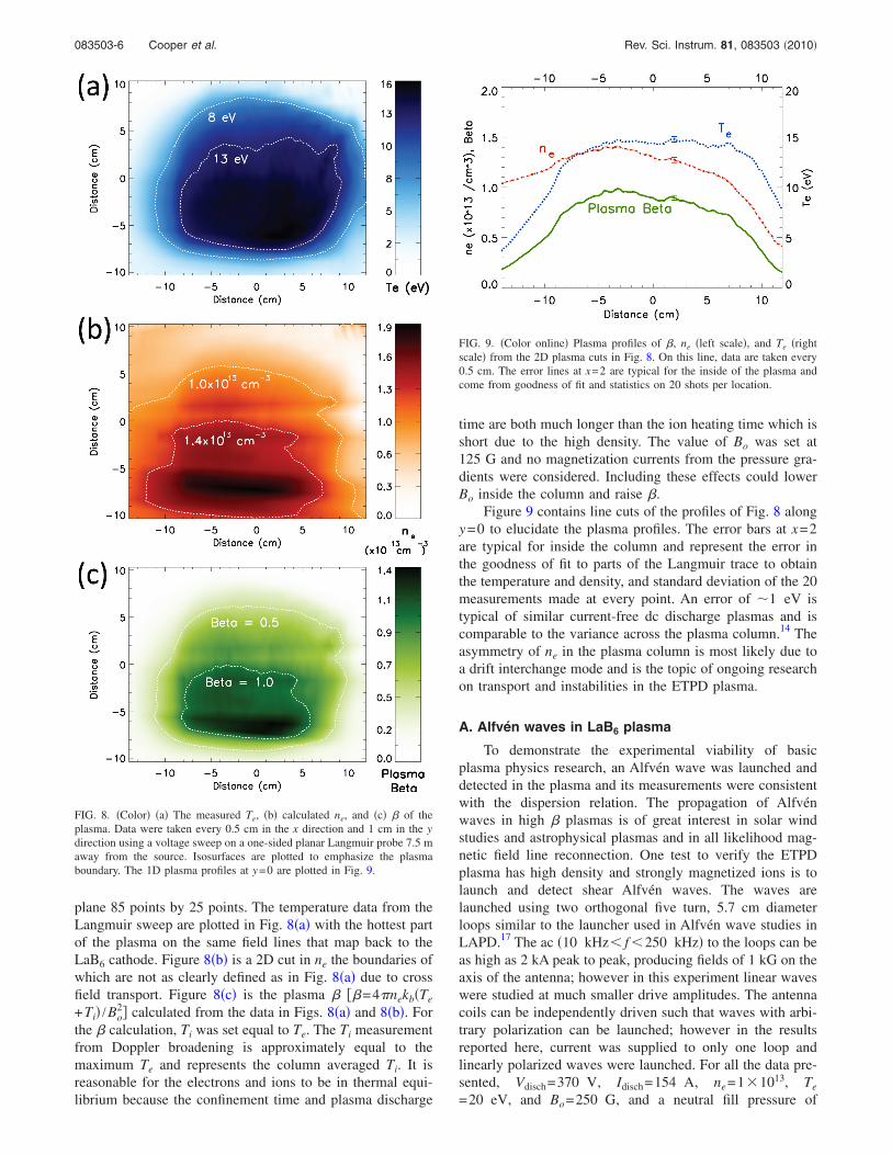
plane 85 points by 25 points. The temperature data from theLangmuir sweep are plotted in Fig. 8�a� with the hottest partof the plasma on the same field lines that map back to theLaB6 cathode. Figure 8�b� is a 2D cut in ne the boundaries ofwhich are not as clearly defined as in Fig. 8�a� due to crossfield transport. Figure 8�c� is the plasma � ��=4�nekb�Te
+Ti� /Bo2� calculated from the data in Figs. 8�a� and 8�b�. For
the � calculation, Ti was set equal to Te. The Ti measurementfrom Doppler broadening is approximately equal to themaximum Te and represents the column averaged Ti. It isreasonable for the electrons and ions to be in thermal equi-librium because the confinement time and plasma discharge
time are both much longer than the ion heating time which isshort due to the high density. The value of Bo was set at125 G and no magnetization currents from the pressure gra-dients were considered. Including these effects could lowerBo inside the column and raise �.
Figure 9 contains line cuts of the profiles of Fig. 8 alongy=0 to elucidate the plasma profiles. The error bars at x=2are typical for inside the column and represent the error inthe goodness of fit to parts of the Langmuir trace to obtainthe temperature and density, and standard deviation of the 20measurements made at every point. An error of �1 eV istypical of similar current-free dc discharge plasmas and iscomparable to the variance across the plasma column.14 Theasymmetry of ne in the plasma column is most likely due toa drift interchange mode and is the topic of ongoing researchon transport and instabilities in the ETPD plasma.
A. Alfvén waves in LaB6 plasma
To demonstrate the experimental viability of basicplasma physics research, an Alfvén wave was launched anddetected in the plasma and its measurements were consistentwith the dispersion relation. The propagation of Alfvénwaves in high � plasmas is of great interest in solar windstudies and astrophysical plasmas and in all likelihood mag-netic field line reconnection. One test to verify the ETPDplasma has high density and strongly magnetized ions is tolaunch and detect shear Alfvén waves. The waves arelaunched using two orthogonal five turn, 5.7 cm diameterloops similar to the launcher used in Alfvén wave studies inLAPD.17 The ac �10 kHz� f �250 kHz� to the loops can beas high as 2 kA peak to peak, producing fields of 1 kG on theaxis of the antenna; however in this experiment linear waveswere studied at much smaller drive amplitudes. The antennacoils can be independently driven such that waves with arbi-trary polarization can be launched; however in the resultsreported here, current was supplied to only one loop andlinearly polarized waves were launched. For all the data pre-sented, Vdisch=370 V, Idisch=154 A, ne=1�1013, Te
=20 eV, and Bo=250 G, and a neutral fill pressure of
FIG. 8. �Color� �a� The measured Te, �b� calculated ne, and �c� � of theplasma. Data were taken every 0.5 cm in the x direction and 1 cm in the ydirection using a voltage sweep on a one-sided planar Langmuir probe 7.5 maway from the source. Isosurfaces are plotted to emphasize the plasmaboundary. The 1D plasma profiles at y=0 are plotted in Fig. 9.
FIG. 9. �Color online� Plasma profiles of �, ne �left scale�, and Te �rightscale� from the 2D plasma cuts in Fig. 8. On this line, data are taken every0.5 cm. The error lines at x=2 are typical for the inside of the plasma andcome from goodness of fit and statistics on 20 shots per location.
083503-6 Cooper et al. Rev. Sci. Instrum. 81, 083503 �2010�
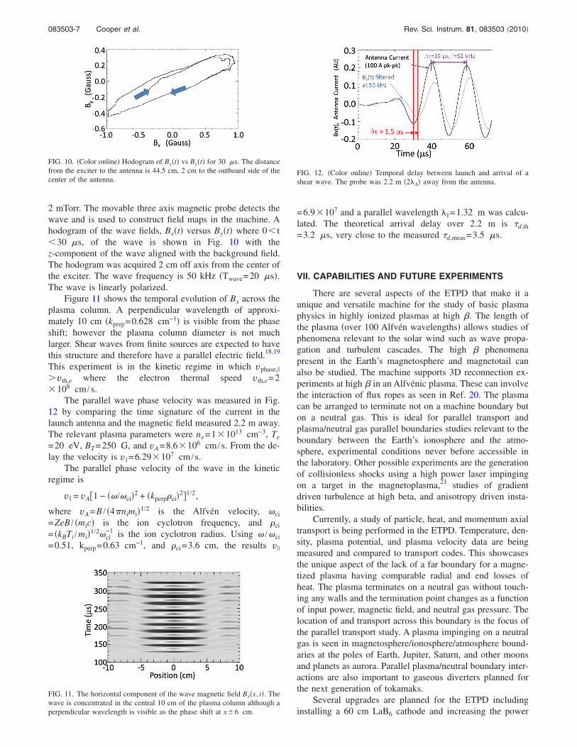
2 mTorr. The movable three axis magnetic probe detects thewave and is used to construct field maps in the machine. Ahodogram of the wave fields, Bx�t� versus By�t� where 0� t�30 �s, of the wave is shown in Fig. 10 with thez-component of the wave aligned with the background field.The hodogram was acquired 2 cm off axis from the center ofthe exciter. The wave frequency is 50 kHz �Twave=20 �s�.The wave is linearly polarized.
Figure 11 shows the temporal evolution of Bx across theplasma column. A perpendicular wavelength of approxi-mately 10 cm �kperp=0.628 cm−1� is visible from the phaseshift; however the plasma column diameter is not muchlarger. Shear waves from finite sources are expected to havethis structure and therefore have a parallel electric field.18,19
This experiment is in the kinetic regime in which vphase,�
�vth,e where the electron thermal speed vth,e=2�108 cm /s.
The parallel wave phase velocity was measured in Fig.12 by comparing the time signature of the current in thelaunch antenna and the magnetic field measured 2.2 m away.The relevant plasma parameters were ne=1�1013 cm−3, Te
=20 eV, BT=250 G, and vA=8.6�106 cm /s. From the de-lay the velocity is v� =6.29�107 cm /s.
The parallel phase velocity of the wave in the kineticregime is
v� = vA�1 − � / ci�2 + �kperpci�2�1/2,
where vA=B / �4�nimi�1/2 is the Alfvén velocity, ci
=ZeB / �mic� is the ion cyclotron frequency, and ci
= �kBTi /mi�1/2 ci−1 is the ion cyclotron radius. Using / ci
=0.51, kperp=0.63 cm−1, and ci=3.6 cm, the results v�
=6.9�107 and a parallel wavelength �� =1.32 m was calcu-lated. The theoretical arrival delay over 2.2 m is �d,th
=3.2 �s, very close to the measured �d,meas=3.5 �s.
VII. CAPABILITIES AND FUTURE EXPERIMENTS
There are several aspects of the ETPD that make it aunique and versatile machine for the study of basic plasmaphysics in highly ionized plasmas at high �. The length ofthe plasma �over 100 Alfvén wavelengths� allows studies ofphenomena relevant to the solar wind such as wave propa-gation and turbulent cascades. The high � phenomenapresent in the Earth’s magnetosphere and magnetotail canalso be studied. The machine supports 3D reconnection ex-periments at high � in an Alfvénic plasma. These can involvethe interaction of flux ropes as seen in Ref. 20. The plasmacan be arranged to terminate not on a machine boundary buton a neutral gas. This is ideal for parallel transport andplasma/neutral gas parallel boundaries studies relevant to theboundary between the Earth’s ionosphere and the atmo-sphere, experimental conditions never before accessible inthe laboratory. Other possible experiments are the generationof collisionless shocks using a high power laser impingingon a target in the magnetoplasma,21 studies of gradientdriven turbulence at high beta, and anisotropy driven insta-bilities.
Currently, a study of particle, heat, and momentum axialtransport is being performed in the ETPD. Temperature, den-sity, plasma potential, and plasma velocity data are beingmeasured and compared to transport codes. This showcasesthe unique aspect of the lack of a far boundary for a magne-tized plasma having comparable radial and end losses ofheat. The plasma terminates on a neutral gas without touch-ing any walls and the termination point changes as a functionof input power, magnetic field, and neutral gas pressure. Thelocation of and transport across this boundary is the focus ofthe parallel transport study. A plasma impinging on a neutralgas is seen in magnetosphere/ionosphere/atmosphere bound-aries at the poles of Earth, Jupiter, Saturn, and other moonsand planets as aurora. Parallel plasma/neutral boundary inter-actions are also important to gaseous diverters planned forthe next generation of tokamaks.
Several upgrades are planned for the ETPD includinginstalling a 60 cm LaB6 cathode and increasing the power
FIG. 11. The horizontal component of the wave magnetic field Bx�x , t�. Thewave is concentrated in the central 10 cm of the plasma column although aperpendicular wavelength is visible as the phase shift at x�6 cm.
FIG. 12. �Color online� Temporal delay between launch and arrival of ashear wave. The probe was 2.2 m �2�A� away from the antenna.
FIG. 10. �Color online� Hodogram of Bx�t� vs By�t� for 30 �s. The distancefrom the exciter to the antenna is 44.5 cm, 2 cm to the outboard side of thecenter of the antenna.
083503-7 Cooper et al. Rev. Sci. Instrum. 81, 083503 �2010�
supplies to accommodate magnetic fields up to 750 G. Thiswould greatly increase the versatility of the plasma createdby the LaB6 source.
ACKNOWLEDGMENTS
The authors thank Marvin Drandell for his invaluablehelp with fabrication and construction of multiple systems ofthe ETPD, Mio Nakamoto for probe construction, Steve Vin-cena for helping to design the automated probe drive soft-ware, and Lothar Schmidtz for help with line ratio and Dop-pler broadening temperature measurements. The authorwould also like to thank Kim DeRose and Robert Niederriterfor their help in construction and measurements through theNSF-REU program. This project was implemented at the Ba-sic Plasma Science Facility at UCLA and supported by theDepartment of Energy �Grant No. FC02-07ER54918� andNational Science Foundation �Grant No. NSF-PHY-053162�.
1 J. M. Lafferty, J. Appl. Phys. 22, 299 �1951�.2 D. M. Goebel, Y. Hirooka, and T. A. Sketchley, Rev. Sci. Instrum. 56,1717 �1985�.
3 K. S. Chung, H.-J. Woo, G.-S. Choi, J.-J. Do, Y.-J. Seo, and H.-J. You,Contrib. Plasma Phys. 46, 4 �2006�.
4 D. M. Goebel, J. T. Crow, and A. T. Forrester, Rev. Sci. Instrum. 49, 469�1978�.
5 Y. Hirooka, R. W. Conn, A. Sketchley, W. K. Leung, G. Chevalier, R.Doerner, J. Elverum, D. M. Goebel, G. Gunner, M. Khandagle, B. Labom-
bard, R. Lehmer, P. Luong, Y. Ra, L. Schmitz, and G. Tynan, J. Vac. Sci.Technol. 8, 3 �1990�.
6 G. I. Kuznetsov, Phys. Scr., T t71, 39 �1997�.7 S. D. Ferris, D. C. Joy, H. J. Leary, L. D. Longinotti, and P. H. Schmidt,U.S. Patent No. 4,054,946 �18 October 1997�.
8 Available from Cerac Inc., Milwaukee, WI 53201; www.Cerac.com.9 N. Bhatnagar and T. S. Srivastan, Processing and Fabrication of Ad-vanced Materials XVII �I.K International Publishing House, New Delhi,India, 2009�, Vol. 1, p. 258.
10 Available from Poco Graphite, Inc., Decateur, TX 76234; www.Poco.com.11 P. Pribyl and W. Gekelman, Rev. Sci. Instrum. 75, 669 �2004�.12 P. D. Prewett and J. E. Allen, Proc. R. Soc. London, Ser. A 348, 435
�1976�.13 A. Fruchtman, G. Makrinich, and J. Ashkenazy, Plasma Sources Sci.
Technol. 14, 152 �2005�.14 W. Gekelman, H. Pfister, Z. Lucky, J. Bamber, D. Leneman, and J.
Maggs, Rev. Sci. Instrum. 62, 2875 �1991�.15 I. G. Brown, A. B. Compher, and W. B. Kunkel, Phys. Fluids 14, 1377
�1971�.16 E. Everson, P. Pribyl, C. G. Constantin, A. Zylstra, D. Schaeffer, N. L.
Kugland, and C. Niemann, Rev. Sci. Instrum. 80, 113505 �2009�.17 A. Gigliotti, W. Gekelman, P. Pribyl, S. Vincena, A. Karavaev, X. Shao,
A. Surjalal Sharma, and D. Papadopolous, Phys. Plasmas 16, 092106�2009�.
18 D. Leneman, W. Gekelman, and J. Maggs, Phys. Rev. Lett. 82, 2673�1999�.
19 G. J. Morales and J. E. Maggs, Phys. Plasmas 4, 4118 �1997�.20 E. E. Lawrence and W. Gekelman, Phys. Rev. Lett. 103, 105002 �2009�.21 C. Constantin, W. Gekelman, P. Pribyl, E. Everson, D. Schaeffer, N.
Kugland, R. Presura, S. Neff, C. Plechaty, S. Vincena, A. Collette, S.Tripathi, M. Villagran Muniz, and C. Niemann, Astrophys. Space Sci.322, 155 �2009�.
083503-8 Cooper et al. Rev. Sci. Instrum. 81, 083503 �2010�