Embed Size (px)
Citation preview
Calhoun: The NPS Institutional Archive
Theses and Dissertations Thesis Collection
1990-06
A Mission Planning Expert System with
Three-Dimensional Path Optimization for the NPS
Model 2 Autonomous Underwater Vehicle
Ong, Seow Meng
Monterey, California. Naval Postgraduate School
http://hdl.handle.net/10945/23457
This document was downloaded on November 07, 2013 at 13:17:32
Author(s) Ong, Seow Meng
Title A Mission Planning Expert System with Three-Dimensional Path Optimization for theNPS Model 2 Autonomous Underwater Vehicle
Publisher Monterey, California. Naval Postgraduate School
Issue Date 1990-06
URL http://hdl.handle.net/10945/23457
DT~FILE COP~' jNAVAL POSTGRADUATE SCHOOL
Monterey, California
DTIC, SEP 13 1990 z
S DS D 0S DIONT
LI)0Y)
THESISA MISSION PLANNING EXPERT SYSTEM
WITH THREE-DIMENSIONAL PATH OPTIMIZATIONFOR THE NPS MODEL 2
AUTONOMOUS UNDERWATER VEHICLE
by
Seow Meng Ong
June, 1990
Thesis Advisor: Se-Hung Kwak
Approved for public release; distribution is unlimited.
9.0 09 1.2 014
UnclassifiedSecurity Classification of this page
REPORT DOCUMENTATION PAGEla Report Security Classification Unclassified lI b Restrictive Markings2a Security Classification Authority 3 Distribution Availability of Report2b Declassification/Downgrading Schedule Approved for public release; distribution is unlimited.4 Performing Organization Report Number(s) 5 Monitoring Organization Report Number(s)6a Name of Performing Organization 6b Office Symbol 7a Name of Monitoring OrganizationNaval Postgraduate School I (If Applicable) 52 Naval Postgraduate School6c Address (city, state, and ZIP code) 7b Address (city, state, and ZIP code)Monterey, CA 93943-5000 Monterey, CA 93943-50008a Name of FundingiSpoasoring Organization 8 8b Office Symbol 9 Procurement Instrument Identification Number
I(If Applicable)8c Address (city, state, and ZIP code) 10 Source of Funding Numbers
_________________________________!__ = Elcent Number IPmoe No ITssk No IWo*k Unit Aocemnm No
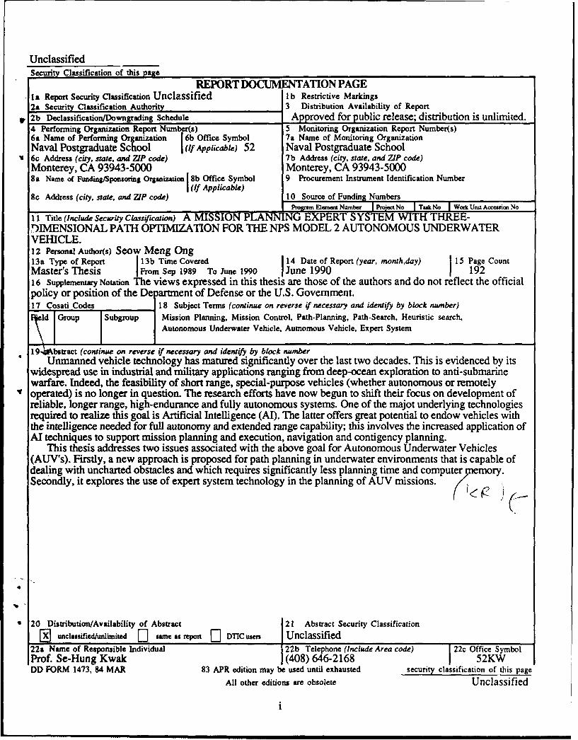
11 Title (Include Security Classification) A MISSION PLANNING EXPERT SYSTEM WITH THREE-D)IMENSIONAL PATH OPTIMIZATION FOR THE NPS MODEL 2 AUTONOMOUS UNDERWATERVEHICLE.12 Personal Author(s) Seow Meng Ong13a Type of Report 13b Time Covered 14 Date of Report (year, month,day) 15 Page CountMaster's Thesis IFrom Sep 1989 To June 1990 June 1990 19216 Supplementary Notation The views expressed in this thesis are those of the authors and do not reflect the officialpolicy or position of the De )artment of Defense or the U.S. Government.17 Cosati Codes 18 Subject Terms (continue on reverse if necessary and identify by block number)
d Group Subgroup Mission Planning, Mission Control, Path-Planning, Path-Search, Heuristic search,Autonomous Underwater Vehicle, Autnomous Vehicle. Expert System
19, bstract (continue on reverse if necessary and identify by block numberUnmanned vehicle technology has matured significantly over the last two decades. This is evidenced by its
widespread use in industrial and military applications ranging from deep-ocean exploration to anti-submarinewarfare. Indeed, the feasibility of short range, special-purpose vehicles (whether autonomous or remotelyoperated) is no longer in question. The research efforts have now begun to shift their focus on development ofreliable, longer range, high-endurance and fully autonomous systems. One of the majot underlying technologiesrequired to realize this goal is Artificial Intelligence (AI). The latter offers great potential to endow vehicles withthe intelligence needed for full autonomy and extended range capability; this involves the increased application ofAl techniques to support mission planning and execution, navigation and contigency planning.
This thesis addresses two issues associated with the above goal for Autonomous Underwater Vehicles(AUV's). Firstly, a new approach is proposed for path planning in underwater environments that is capable ofdealing with uncharted obstacles and which requires significantly less planning time and computer emory.Secondly, it explores the use of expert system technology in the planning of AUV missions.
20 Distribution/Availability of Abstract 21 Abstract Security Classification
0 unclassified/unlimited 11 same as repot DTIC users Unclassified22a Name of Responsible Individual 22b Telephone (Include Area code) 22c Office Symbol
Prof. Se-Hung Kwak (408) 646-2168 52KWDD FORM 1473, 54 MAR 83 APR edition may be used until exhausted security classification of this page
All other editions are obsolete Unclassified
i
Approved for public release; distribution is unlimited.
A MISSION PLANNING EXPERT SYSTEM I
WITH THREE-DIMENSIONAL PATH OPTIMIZATION
FOR THE
NPS MODEL 2 AUTONOMOUS UNDERWATER VEHICLE
by
Scow Meng OngB. Eng., National University of Singapore, 1983
Submitted in partial fulfillment
of the requirements for the degree of
MASTER OF SCIENCE IN COMPUTER SCIENCE
from the
NAVAL POSTGRADUATE SCHOOL
June 1990
Author: /.2Sow Meng Ong
Approved by:Se- ung wak, Thesis Advisor
Robert B. McGhee, Second Reader
Robert B. McGhee, Chairman, Department of Computer Science
ii
ABSTRACT
Unmanned vehicle technology has matured significantly over the last two decades.
This is evidenced by its widespread use in industrial and military applications ranging from
deep-ocean exploration to anti-submarine warfare. Indeed, the feasibility of short-range,
special-purpose vehicles (whether autonomous or remotely operated) is no longer in
question. The research efforts have now begun to shift their focus on development of
reliable, longer-range, high-endurance and fully autonomous systems. One of the major
underlying technologies required to realize this goal is Artificial Intelligence (AI). The latter
offers great potential to endow vehicles with the intelligence needed for full autonomy and
extended range capability; this involves the increased application of A techniques to
support mission planning and execution, navigation and contingency planning.
This thesis addresses two issues associated with the above goal for Autonomous
Underwater Vehicles (AUV's). Firstly, a new approach is proposed for path planning in
underwater environments that is capable of dealing with uncharted obstacles and which
requires significantly less planning time and computer memory. Secondly, it explores the
use of expert system technology in the planning of AUV missions.
Accesion For
I NTIS CRA&IDTIC TAB 0@* Unannouncedl 0-
' Justification
.ByDistribution I
Availability Codes
111 - Avail and IerDist~ Special
A.1
TABLE OF CONTENTS
L INTRODUCTION ................................................................................ I
A. BACKGROUND ............................................................................ 1B. MISSION PLANNING EXPERT SYSTEM ................................... 2C. PATH PLANNING ..................................................................... 4
1. Route Planning vs Path Planning ........................................... 42. Search Methods in Path Planning ........................................... 5
D. SCOPE OF THESIS ..................................................................... 7E. THESIS ORGANIZATION .......................................................... 7
I. SURVEY OF PREVIOUS WORK ..................................................... 9
A. INTRODUCTION ...................................................................... 9B. ARCHITECTURES FOR MISSION PLANNING AND CONTROL ... 10
1. Blackboard Based Systems ................................................... 10
2. Situation Based Control Architecture .................................... 14
3. Value-Driven Hierarchical Structure ................................... 16
C. PATH PLANNING ALGORITHMS ........................................... 17D. SUMMARY ............................................................................. 21
HLI. DETAILED PROBLEM STATEMENT ........................................... 22
A. INTRODUCTION .................................................................... 22
B. NPS AUV PHYSICAL CHARACTERISTICS ............................... 22
C. CONTROL SYSTEM ARCHITECTURE ..................................... 25D. MISSIONS ................................................................................ 28
E. PATH PLANNING ASSUMPTIONS .......................................... 29
1. Environment Model .......................................................... 29
2. Obstacle Model ................................................................. 31
3. Vehicle Model ................................................................. 31
4. Sensor Model .................................................................... 32
F. SIMULATION FACILITIES ...................................................... 32
iv
G . SUM M ARY ............................................................................. 33
IV. MISSION PLANNING EXPERT SYSTEM ........................................ 34
A. SOFTWARE ARCHITECTURE OVERVIEW.............................. 34
B. REPRESENTATION OVERVIEW ............................................ 39
C. THE MISSION PLANNER ....................................................... 40
1. The Knowledge Processor ................... .................... 42
2. The Voters ...... ........................................... 46
3. The Decision Maker........................................................... 48
D. MISSION PLANNING WORKSTATION ................................... 49
1. Purpose and Design Considerations..................................... 49
2. An Illustrative Example ...................................................... 50
E. SUM M ARY ...................... ...... ............................................ 57
V. HEUJRISTIC SEARCH ...... ......... o... .o ...... -..... o..... o...... o........................ 58
A. INTRODUCTION ..... ...................................... 58
B. PRELIMINARY DEFINITIONS AND NOTATIONS .................... 59
C. SUCCESSOR POSITIONS ......................................................... 61
D. HEURISTICS ........ .. .......................................... 64
E. ENERGY COST MEASURE ............................................ 66
F. EVALUATION FUNCTION................................................. 67
1. Local Cost Function (LC) .................................................... 67
2. Estimated Cost Function (EC) .............................................. 69
G. OBSTACLE CLEARANCE ....................................................... 72
H. MODES OF OPERATION ........................................................ 75
1. O verview ................. ........ ............................................. 75
2. Norm al M ode.................. ............................................. 77
3. Obstacle M ode ................................................................. 79
4. Obstacle-Edge Mode ........ ............................... 81
I. AN ILLUSTRATIVE EXAMPLE ............................................... 82
J. SU M M A RY ............................................................................. 86
v
VI. PATH PLANNING EXPERIMENTAL RESULTS ................................. 88
A . INTRODUCTION ........................................................................ 88
B . SCEN ARIO S ............................................................................... 88
C. MEASURES OF PERFORMANCE ............................................. 90
D. RESULTS AND ANALYSIS ...................................................... 90
1. Quantitative Analysis .......................................................... 90
2. Qualitative Comparison Of Heuristic And A* Paths ................ 95
E . SU M M A RY ................................................................................ 105
VIL SUMMARY AND CONCLUSIONS ..................................................... 106
A. RESEARCH CONTRIBUTIONS ................................................... 106
B. RESEARCH EXTENSIONS ......................................................... 109
LIST OF REFERENCES ........................................................................... 114
APPENDIX A SCENARIO DEFINITIONS ............................................ 117
APPENDIX B AUV TESTBED SIMULATOR USER MANUAL........... 118
APPENDIX C FILE ORGANIZATION ................................................ 126
APPENDIX D PROGRAM LIST ........................................................... 129
INITIAL DISTRIBUTION LIST ................................................................ 182
Ai
ACKNOWLEDGEMENTS
The original code for the NPS AUV graphical simulator to which enhancements
were made during this research, was developed by Dave Marco, Ray Rogers, and
Mike Schwartz. The network communications software was not modified and was
written by Ted Barrow, Se-Hung Kwak, Bill Teter, and Larry Shannon.
I would like to thank ?rofessor Se-Hung Kwak for his invaluable advice and
assistance rendered especially during the development work on the LISP machines. I
am also grateful to Professor Robert McGhee for his constructive comments and
overall guidance to the project. Both professors have been very encouraging and
supportive and it has been a real pleasure working with them.
My sincere thanks also to Mr. Albert Wong and his colleagues of the Computer
Science Department Technical Support Staff for their professional support in
debugging the communications software.
Most of all, I thank my wife and son for their unfailing love, support and
understanding, without which the success of this work would not have been possible.
vii
I. INTRODUCTION
A. BACKGROUND
The last two decades witnessed significant progress in unmanned vehicle
technology. This, coupled with advances in computer and Artificial Intelligence (AI)
research has increased the likelihood of realizing effective unmanned autonomous
undersea vehicles in the near future. With the maturity in the basic technologies
required, the research focus has begun to shift towards the development of more
reliable, longer range, higher endurance and fully autonomous systems. In line with
these developments, the Naval Postgraduate School (NPS) is currently constructing an
experimental Autonomous Underwater Vehicle (AUV) to support research on the
technology issues related to the above challenge.
In conjunction with research efforts on the vehicle design, previous student thesis
studies [Ref. 1, 2] have also centered on the creation of a "laboratory testbed
environment" for testing AUV mission planning, navigation, and control issues using
simulated environments. The testbed is comprised of a visual simulator (a high-
resolution graphics workstation) linked to a special-purpose Al workstation. The latter
is used for prototyping AI software for mission planning and control while the visual
simulator facilitates 3-D visualization of the AUV behavior during tests. The whole
setup is aimed at providing effective and quick feedback on the results and thus
reducing the overall time and expense of AUV subsystem development.
m I
This thesis is devoted to the investigation of two inter-related issues, namely,
mission planning and path planning for Autonomous Underwater Vehicles, both of
which are issues central to the development of completely autonomous vehicles. In the
process, the laboratory testbed mentioned above is used to demonstrate and validate
the results.
B. MISSION PLANNING EXPERT SYSTEM
Mission plans can be constructed at different levels of abstraction. At the highest
levels, they are mission specifications, detailing the mission objectives, the mission
tasks and the constraints under which the mission is to be executed. At the lower
levels, they list the phases of the mission and detail the tactical actions to be taken in
each phase. The task of transforming the high-level mission specifications to low-level
plans is presently done by the human mission planner. However, with the growing
maturity of expert systems technology, it has become increasingly feasible to develop
systems that automatically perform this translation.
In AUV applications, a major output of the planning process is the route or path
to be taken by the vehicle. The path derived should be consistent with the high-level
mission objectives and, in particular, should satisfy the mission constraints. The
complexity of this task depends on the number and type of constraints. The latter can
be imposed by the vehicle, by the environment in which it is to operate, and by the
2

nature of the mission. Vehicle-related constraints result from the physical
characteristics of the vehicle (such as size and weight), its dynamics (and hence
maneuverability), and the degree of control available. Environmental constraints can
be natural or man-made; for instance, a minefield presents as much an obstacle to a
vehicle as rough undersea terrain. Finally, the nature of the mission refers to factors
such as the time-urgency of the mission, the need for stealth (detection avoidance) or
for threat avoidance.
Fortunately, many path-search algorithms exist in the Al field [Ref. 3, 4, 5, 6, 7,
81, each having its inherent advantages and disadvantages. As will be explained in the
next section, some algorithms provide optimal shortest path solutions, while others
minimize the time required for planning. However, since it is inappropriate for the
human planner to be thoroughly familiar with the characteristic strengths and
weaknesses of all available algorithms, the use of an automated planning tool would
be highly desirable. This thesis explores one approach to designing an expert system
that selects the best path-planning algorithm for the mission, based on the projected
balance between mission factors such as time, energy, risk, etc.
3
C. PATH PLANNING
1. ROUTE PLANNING vs PATH PLANNING
Path planning aims at deriving a well defined path for the vehicle that
satisfies the constraints and requirements of a mission. This can be done in two stages,
first at the macro-level and then at the micro-level. In order to differentiate between
the two, henceforth, the macro-level path planner shall be referred to as the route
planner, and the micro-level route planner as the path planner. Macro-level route
planning takes a macroscopic view of the area of operation by partitioning it into
regions such as sonobouy fields, unnavigable areas, minefields, search areas, and so
forth. To do this, a priori intelligence information concerning the environment may be
required. The best route, made up of a sequence of joined path-segments passing
through or avoiding specific regions and satisfying the high-level mission objectives
and constraints, is then determined and selected from among possible alternatives.
The requirement for a micro-level path planner is dependent on the agent
that will ultimately traverse the route. By agent is meant some entity capable of
independent motion along a given path. If the agent is man, then the output of the
route planner would be sufficient. However, for a land-based autonomous robot or
vehicle, for instance, this is inadequate since it must also account for micro-level
problems such as avoiding pits, local steep slopes and physical objects along the path.
Thus the role of the path-planner is to derive a detailed path for each path-segment of
4
the route chosen. This can be done in the pre-execution phases and then modified as
necessary during execution whenever unforseen events or obstacles are encountered.
2. SEARCH METHODS IN PATH PLANNING
Invariably, some form of search [Ref. 9] technique in the Artificial
Intelligence domain is employed in path-planning. Search can be defined as the
systematic exploration of the different possibilities that potentially offer a solution.
Many search strategies exist, the classical ones being Depth-first, Breadth-first, Best-
first, A* [Ref. 9, 10], etc. Variants of these have also been used in numerous
applications. In determining the suitability of a search technique, there are two
important application-related factors which must be considered - the size of the search
space and the availability of a priori information concerning the environment.
The practicality of a search method is highly dependent on the size of the
search space because of the physical limitations in the computational time and space
resources of a computer. For instance, exhaustive search techniques, such as the
breadth-first strategy, are not practical for applications with a large search space.
One measure of the size of a search space is the branching factor [Ref. 9,
10], which is defined as the average number of alternatives at each decision point or
node (the average number of successors possessed by each node) in a decision tree.
For instance, in a 2-dimension path-planning problem, each position on a rectangular
grid has 8 neighbors resulting in a branching factor of 8. Heuristics are often used to
5
reduce the branching factor, thereby making feasible an otherwise impractical
technique. In the underwater environment, however, the problem is compounded by
an additional dimension. Unlike two-dimensional path-finding problems, each location
on a three-dimensional grid has 26 alternatives (Figure 5.1). A massive but intelligent
pruning of the search tree is therefore required, if a technique is to be viable.
The second factor - the availability of a priori information concerning the
environment - partitions search methods for path-planning into two categories:
1. Methods which require a priori terrain/environment information. Most
classical search techniques and their variants fall exclusively under this category.
2. Methods which do not require such a priori information. The methods
in this category inevitably, require some form of sensing devices, such as vision
sensors, ultrasonic sensors or contact sensors. In reality, situations possessing complete
a priori information on the environment or terrain are few. Even where a priori
information is available, such data may not be accurate or complete due to the
dynamic nature of the environment. Examples include enemy territory and uncharted
areas. Thus, if vehicles are to be completely autonomous, they must be endowed with
the capability to perform without complete information. Published work relating to this
area is scarce.
6
D. SCOPE OF THESIS
This study is focussed specifically on three objectives:
1. To present the software design of a mission planning expert system which
transforms high-level mission specifications into detailed low-level plans.
2. To develop a viable path-search strategy for underwater environments, called
Heuristic Search.
3. To compare the performance of 3 different search strategies for path
planning, namely, Best-first, A*, and Heuristic search.
E. THESIS ORGANIZATION
Since this thesis has two distinct parts, namely, the design of a Mission Planning
Expert System, and the design of Heuristic Search strategy for path-planning, this
thesis document could either adopt a bottom-up or a top-down approach to describing
the work. After much deliberation, it was decided that a top-down approach would be
advantageous in helping the reader to better appreciate the low-level details of path
planning, if an overview of the system is first presented.
Chapter II reviews previous and ongoing work in the area of mission planning
and control for AUY's, and in the area of path planning search methods. In particular,
the different system architectures that have been proposed for mission planning and
control are briefly described.
7
Chapter III presents a detailed problem statement for this thesis. First, the
physical characteristics of the current vehicle and the proposed control architecture are
discussed in order to provide an overview of the system. The models and assumptions
on which this thesis is based are then presented together with a description of the
laboratory testbed simulator.
Chapter IV presents the internals of the Mission Planning Expert System. It
expounds on the top-level software architecture and explains how each entity is
represented within the system. It then proceeds with a description of the detailed
design for each functional component. Finally, the reader is led through an illustrative
example of how a specific mission is planned using the Mission Planning Workstation
developed.
Chapter V describes the methodology of the Heuristic path-search strategy. It
explains each component concept in detail, and shows how it influences the vehicle's
decision on the path to take to reach the goal. Chapter VI follows up with a
comparative study of the three path-search strategies, namely A*, Best-first, and
Heuristic search. The detailed results of several simulations, which were run in order
to derive their relative performances, are presented.
Finally, Chapter VII summarizes the contributions of this thesis and suggests
further extensions to the project.
8
II. SURVEY OF PREVIOUS WORK
A. INTRODUCTION
The ultimate research goal in the area of mission planning and control for AUV's
is to enable a vehicle to operate autonomously without human intervention in its
fulfillment of a given mission. This can only be achieved if the vehicles are endowed
with the intelligence required to respond to, or deal with, unforseen situations. The
realization of such behavior involves automating some of the important high-level
functions, such as planning, planning-control, and decision-making, which are
ordinarily undertaken by a human planner. To satisfy this objective, the ardent efforts
of the AUV research community have resulted in a variety of innovative strategies and
corresponding system architectures for mission planning and control. The major ones
are discussed in this chapter.
In the domain of path planning and navigation for autonomous vehicles in
general, as will be seen, much of tie early research work relied on several
fundamental premises. Firstly, most previous research is targeted for robotic
applications in two-dimensional environments. Secondly, all obstacles are typically
approximated by polyhedral shapes to simplify the algorithm. A third fundamental
assumption is that a priori information on the environment is available; where this is
9
untrue, the algorithms proposed require the robots to first "learn" about the
environment, and to form its own model concerning the world [Ref. 11], prior to
actual navigation.
B. ARCHITECTURES FOR MISSION PLANNING AND CONTROL
1. BLACKBOARD BASED SYSTEMS
In recent years, there has been considerable interest in the use of
"blackboard" architectures as the structural design paradigm for knowledge-based
control architectures onboard AUV's [Ref. 12, 13, 14]. The methodology derives its
name from the organized global data space where all system data is placed: the
blackboard. An example is the ongoing research work at the Marine Systems
Engineering Laboratory (MSEL) at the University of New Hampshire [Ref. 12], where
a Blackboard Control Architecture (BCA) is used for an experimental AUV route
planner, named the "Supervisor". The focus of the work is on route planning. Given
a high level mission specification consisting of an unordered list of way-points to visit
and surveys to run, the system works out a route connecting the mission tasks and
issues intermediate level motion commands that describe the route.
The Supervisor views a route problem as two distinct problems: the domain
problem of actually planning a route and the control problem of how to go about
planning the route. Thus, a dual blackboard architecture is used to separate the two,
10
resulting in two distinct components in the system: the route planning subsystem and
the control planning subsystem. Each component is comprised of a blackboard and a
pool of knowledge sources. The knowledge source pools possess the procedural
knowledge while the data generated and used by those knowledge sources is "written"
on the blackboards. A knowledge source is an independent process that acts as a
specialist in some particular area of the problem. Knowledge sources have a
condition/action format. They "trigger" and become executable if their conditions
evaluate to true, in which case, a Knowledge Source Activation Record (KSAR) is
generated and stored in an agenda of KSARs waiting to be executed. When selected
for running, the action portion is executed and any output from it is posted either as
new information or as an update on the blackboard. This posting or modification on
the blackboard is referred to as an "event".
The system solves the route planning problem in the following manner. The
user posts a mission specification on the control blackboard as an input. The system
then attempts to trigger the knowledge sources based on that event. If one or more are
triggered, only one is selected and executed generating one or more new events. These
new events in turn cause other knowledge sources to be triggered, and perhaps
execute. An "independent cooperation" among the knowledge sources ensues with
knowledge sources triggering on events, executing their actions (one knowledge source
per inference cycle), and posting the results of their actions on either blackboard. The
11
route planning knowledge sources work out the details of the mission path and the
control knowledge sources specify the order of route planning knowledge source
execution. The solutions to both problems are incrementally generated on the
blackboards and the final output of the Supervisor is a set of motion-commands pairs
such as "goto x y z; do operation xxx".
At the heart of the control mechanism is the scheduling strategy used to
choose the next KSAR from the agenda for execution. The scheduler plays a crucial
role in influencing the outcome of the plans since it determines the planning behavior
(i.e., the process by which the system generates the solution). Two strategies are used
in the Supervisor, namely, successive refinement and Last-In-First-Out (LIFO)
strategies. Successive refinement strategy directs the domain problem solution through
its abstraction levels from the most abstract down to the most detailed so that
knowledge sources at the higher abstraction levels have greater priority for execution.
The LIFO strategy simply chooses the most recent KSAR for execution.
The Supervisor is currently designed to adopt one of the two strategies
based on only one context parameter, namely, the time available to plan the mission
which is part of the mission specification. If the allowable planning time is greater
than a limit, successive refinement is chosen, otherwise the default LIFO strategy is
used. This policy is adopted because results show that successive refinement strategy
takes longer time to plan than LIFO and is thus less desirable when allowable
planning time is low.
12
Currently, there are several issues that are not (yet) addressed by the
system. Factors such as energy, risk, need for stealth and detection avoidance, etc.,
which are usually critical to a mission have not been considered. Moreover, the route
planner assumes way-points are given, so that the problem reduces to one of
sequencing them instead of deriving them from a priori environmental knowledge.
Perhaps the more important questions relate to the architecture itself. Mayer [Ref. 15]
points out several potential shortfalls with regard to blackboard architectures for
mission control:
1. Lack of predictability, traceability and reliability of operation.
2. Inability to scope the effect of the data generated in the reasoning
process.
3. High levels of communication traffic in a loosely coupled architecture.
4. Explosive increase in complexity of the "scheduler" as the number
and complexity of the knowledge sources increases.
5. Inability to implement effective system level error detection and
recovery procedures.
13
2. SITUATION BASED CONTROL ARCHITECTURE
This concept evolved from the blackboard architecture, apparently to effect
a larger distribution of the knowledge based control components to different hardware
processors, and to facilitate easier partitioning of knowledge sources along functional
lines. A prototype Knowledge Based Control System (KBCS) for an AUV, based on
this idea has been implemented at Texas A&M University to demonstrate its feasibility
[Ref. 15].
The KBCS design revolves around the idea of a situation based architecture.
This concept partitions the problem space into non-overlapping regions called
situations. A situation encapsulates the rule sets, domain and declarative knowledge
required to make the decisions, judgements, and actions required of the reasoning
component in the corresponding part of the problem space. Situations can arise from
either external or internal events, or combinations of the two. An entity called the
Anticipator is responsible for monitoring the ongoing events and to "trigger" when
certain scenarios such as "threat detection" or "mission replanning" occurs. When they
trigger, the appropriate situation is retrieved from a situation database; the latter in turn
triggers the actions of the various knowledge source components to deal with the
situation.
In the prototype developed, the knowledge source components correspond
roughly to the major functions of a submarine crew. Each component is hosted on a
separate Symbolics 3640 machine and interconnected via an ethernet network. Five
14
systems were developed, namely, the Skipper, the Navigator, the Engineer, the
Diagnoser and the Facilitator. The Diagnoser is responsible for monitoring the other
subsystems and to initiate recovery procedures when any failure occurs, while the
Facilitator serves the inter-subsystem communication needs.
In a mission planning situation (or scenario), the Skipper, who is generally
responsible for strategic and tactical planning, would request a path from one location
to another from the Navigator. If a path can be found, a series of constrained paths
will be tested. For example, the Skipper may order a path that will avoid standard
shipping lanes. The Navigator will then search for a path that satisfies the constraints.
When a path is returned to the Skipper, the Engineer is requested to perform a
resource analysis for the path. The latter is essentially another constraint on the path
(fuel) that must be considered before a final selection is made. After obtaining one or
more constrained paths from the Navigator, The Skipper selects the mission plan that
best satisfies the mission goals. All this time, the Facilitator serves the inter-subsystem
communication needs.
Thus, unlike the blackboard approach where a single event triggers
individual knowledge sources and where the knowledge sources reason independently,
this approach relies on the anticipation of situations (based on a collation of one or
more events) to trigger the cooperative actions of all the knowledge sour-es to deal
with the task.
15
3. VALUE-DRIVEN HIERARCHICAL STRUCTURE
This approach to automating mission planning and control was first
conceived at the University of New Hampshire under the NBS-UNH AUV program
[Ref. 16]. The methodology emphasizes onboard planning and decision making in
order to respond to unexpected events that may require major revisions in the mission
route or plan, including decisions to omit some tasks originally planned for the
mission.
The central contribution of the research is idea of a value-driven approach
to decision making as opposed to rule-based decision making. In this approach, the
critical mission factors such as vehicle survival, energy constraint, the time urgency
for accomplishment of each task, the need for stealth, etc., are identified. For each
factor, a value-priority indicating its criticality to the overall mission success is
specified by the user. For instance, a value for the vehicles is used to assess the
desirability of plan alternatives that may involve high risk to individual vehicles, or
even the deliberate sacrifice of a vehicle, while a value of stealth for the mission
would indicate the priority assigned to the avoidance of detection during the execution
of the mission, and so forth. Each of the alternative plans is then evaluated in terms
of the value criteria (or mission priorities) and the decision is completed simply by
selecting the single alternative that shows the best projected score.
Except for resource-related constraints, all value-priorities are specified by
the user. Resource constraints such as time and energy are treated differently since
16
their usage (and thus, their value-priorities) can be varied as long as the total
consumption of these resources does not exceed the supply. Using the latter condition,
Lagrangean optimization techniques are applied to search for possible parameters
(comprising the set of priorities as well as the sequence in which the mission tasks are
to be executed) that gives optimal or near-optimal candidate plans with regard to the
overall mission score. Each possible set of priorities is fed to a set of "outcome
calculators" which provide the projected score for the plan.
The process ends with the selection when either a clearly satisfactory
alternative has been identified, or when the available time for a decision has been
exhausted. The output of the planner is the (macro-level) route for the vehicle and the
tasks to be performed in sequence. The key to intelligent behavior in this approach lies
in the correspondence of the valuative criteria with the higher-level objectives; the
replanning that is performed whenever unanticipated circumstances occur enables the
system to respond "intelligently".
C. PATH PLANNING ALGORITHMS
1. NAVIGATION FOR AN INTELLIGENT MOBILE ROBOT
An algorithm described by Crowley [Ref. 31 is designed for a mobile robot
equipped with a rotating ultrasonic range sensor in a two-dimensional environment.
This navigation system is based on a dynamically maintained model of the local
environment, called the composite local model. The composite local model integrates
17
information from the rotating range sensor, the robot's touch sensor, and a pre-leamed
global model as the robot moves through its environment. This work describes
techniques for constructing a line segment description of the most recent sensor scan
(the sensor model), and for integrating such descriptions to build up a model of the
immediate environment (the composite local model). The estimated position of the
robot is corrected by the difference in position between observed sensor signals and
the corresponding symbols in the composite local model. Crowley also describes a
learning technique where the robot develops a global model and a network of places.
The network of places is used in global path planning, while the segments are recalled
from the global model to assist in local path execution. The system is useful for
navigation in a finite, pre-learned and man-made environment such as a house, office,
or factory.
2. ROBOT NAVIGATION IN UNKNOWN TERRAIN USING LEARNED
VISIBILITY GRAPHS
This algorithm, as described in [Ref. 4], deals with the problem of
navigating an autonomous vehicle robot through unexplored terrain containing
obstacles. A two-dimensional terrain, arbitrarily populated by disjoint convex
polygonal obstacles, is assumed. The algorithm is proven to yield a convergent
solution to each path of traversal. Initially, the terrain is explored using a rather
primitive sensor, and the paths of traversal made to be near-optimal. The visibility
graph that models the obstacle terrain is incrementally constructed by integrating the
18
information about the paths traversed so far. At any stage of learning, the partially
learned terrain model is represented as a learned visibility graph, and it is updated
after each traversal. This work proves that the learned visibility graph converges to the
visibility graph with a probability of one when the source and destination points are
chosen randomly. Ultimately, the availability of the complete visibility graph enables
the robot to plan globally optimal paths and also obviates further usage of sensors.
3. LEARNED NAVIGATION PATHS FOR A ROBOT IN
UNEXPLORED TERRAIN
This algorithm is presented in [Ref. 5]. A method of robot navigation is
proposed, which requires no pre-leamed model, makes maximal use of available
information, records and synthesizes information from multiple journeys, and contains
concepts of learning that allow for continuous transition from local to global path
optimum. Their model of the terrain consists of a spatial graph and a Voronoi diagram.
Using acquired sensor data, two-dimensional polygonal boundaries are used to
approximate the actual obstacle surfaces, free space for transit is correspondingly
reduced, and additional nodes mad edges are recorded based on path intersections and
stop points. Navigation planning is gradually accelerated with experience since
improved global map information minimizes the need for further sensor data
acquisition. The method assumes that obstacle locations are unchanging, that
navigation can be successfully conducted using two-dimensional projections, and that
sensor information is precise.
19

4. AUTOMATIC PATH PLANNING FOR A MOBILE ROBOT USING
A MIXED REPRESENTATION OF FREE SPACE
This algorithm, proposed in [Ref. 6], uses a mixed representation of free space
in terms of two shape primitives: generalized cones and convex polygons. Given a set
of polygonal obstacles in space, the planning algorithm first identifies the
neighborhood relations among obstacles and uses these relations to localize the
influence of obstacles on free space description, and then locates critical "channels"
and "passage regions" in the free space. The free space is then decomposed into non-
overlapping geometric-shaped primitives where the channels are represented as
generalized cones similar to those introduced by Brooks [Ref. 71. The passage regions
are represented as convex polygons. Based on this mixed representation of free space,
the planning algorithm uses two different strategies to path plan trajectories inside the
channels and passage regions.
5. HEURISTIC TWO-DIMENSIONAL NAVIGATION ON ROUGH
TERRAIN WITH OBSTACLES
The algorithm is described in [Ref. 81. It is designed for autonomous land
vehicle navigation in situations where no a priori terrain information is available. The
method models the terrain as a regular two-dimensional grid system with height
information stored at each cell. Thus, the path search uses the traditional eight-
neighbor search strategy. The path search process is guided by a set of heuristics
intended to mimic closely what a human navigator would do in similar circumstances.
In the implementation, these heuristics are represented as mathematical functions. For
20
instance, the heuristic to "move toward the destination whenever possible" is captured
in an estimation function, while the rule "try not to visit the positions already
explored" is represented by a path-marking function. A significant contribution of the
work is in the area of obstacle clearance; conceptually, whenever obstacles are
encountered by the vehicle, it is made to detour along the periphery of the obstacle
until the latter is cleared. Results show that for flat or moderately sloped terrain, the
method provides an almost optimal path (in terms of energy required), while highly
sloped terrain yields reasonable paths. It is also highly efficient in the usage of
computer CPU and memory resources. This approach forms the basis of the Heuristic
search developed in this thesis for three-dimensional underwater environments.
D. SUMMARY
This chapter provides a broad survey of research work that has been done in the
area of mission planning and control for Autonomous Underwater Vehicles, and in the
area of path-planning in general. Three different system architectures for mission
planning and control are examined - Blackboard Based systems, the Situation Based
Control Architecture and the Value-driven Hierarchical Architecture. In the area of
path-planning, previous research has concentrated on two-dimensional path-planning
with little attention given to three-dimensional problems. In particular, the methods
surveyed are targeted for land-based vehicular and robotic applications. Published
work on path-planning for underwater environments is scarce.
21
III. DETAILED PROBLEM STATEMENT
A. INTRODUCTION
This thesis further advances the evolutionary development of an automated
mission planning and control system for the NPS-AUV program. A key feature of the
mission planning expert system developed is its ability to select an appropriate path-
search strategy for a particular mission. The output of the system is a detailed path
specification that fulfills the mission requirements and constraints. The path is
constructed using one of three alternative path-search methods, namely, A*, Best-first,
or Heuristic search. In particular, Heuristic search is proposed as a new path-search
strategy for autonomous vehicles in three-dimensional underwater environments.
B. NPS AUV PHYSICAL CHARACTERISTICS
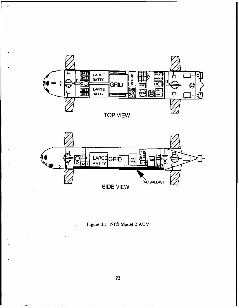
The current vehicle is called the "NPS Model 2 AUV" and is based to a
considerable degree on the earlier, smaller Model 1 AUV described in [Ref. 17]. The
overall appearance and layout of the Model 2 AUV is shown in Figure 3.1. As can be
seen, the vehicle has a rectangular cross-section and is furnished with four forward
control surfaces and four aft control surfaces, as well as four tunnel thrusters. These
thrusters, combined with the two aft screws, provide the vehicle with active control
22
LATYEADALAS
SIDE VIEW
Figure 3.1 NPS Model 2 AUV
23
of five degrees of freedom in a low speed hovering mode, with only the roll degree
of freedom being passively controlled. When the vehicle is operated in its
higher-speed transit mode, thrusters are not used and all six degrees of freedom are
actively controlled using the aft main screws for propulsion and hydrodynamic forces
on the control surfaces to achieve commanded rotational rates in roll, pitch, and yaw.
The total weight of the vehicle is 387 lbs and its length is 93 inches.
As can also be seen from Figure 3.1, the Model 2 AUV is battery powered and
contains two on-board computers, a Gridcase 80386 based laptop computer, and a
Gespac 68030 based real-time control computer. The Gespac computer is furnished
with depth and speed sensors, a complete suite of inertial sensors (3 rate gyros, 3
accelerometers, vertical gyro, directional gyro, and flux-gate compass), and a sonar
system for obstacle avoidance and bottom sounding. As indicated in the figure, the
latter system consists of four fixed-base pencil-beam sonar rangers mounted in a
flooded fiberglass nose cone. One sonar beam looks downward at 45 degrees, another
forward, and the other two are aimed diagonally to the right and left of the forward
looking beam. It is currently anticipated that the Gridcase computer will be
programmed in Common Lisp and will run under the MS-DOS operating system while
the Gespac computer will be programmed in C and will run under OS-9 [Ref. 18].
24
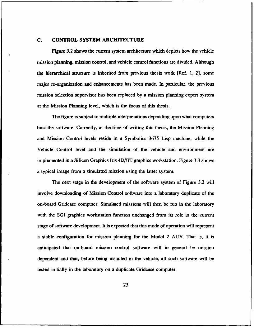
C. CONTROL SYSTEM ARCHITECTURE
Figure 3.2 shows the current system architecture which depicts how the vehicle
mission planning, mission control, and vehicle control functions are divided. Although
the hierarchical structure is inherited from previous thesis work [Ref. 1, 2], some
major re-organization and enhancements has been made. In particular, the previous
mission selection supervisor has been replaced by a mission planning expert system
at the Mission Planning level, which is the focus of this thesis.
The figure is subject to multiple interpretations depending upon what computers
host the software. Currently, at the time of writing this thesis, the Mission Planning
and Mission Control levels reside in a Symbolics 3675 Lisp machine, while the
Vehicle Control level and the simulation of the vehicle and environment are
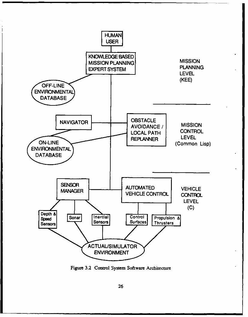
implemented in a Silicon Graphics Iris 4D/GT graphics workstation. Figure 3.3 shows
a typical image from a simulated mission using the latter system.
The next stage in the development of the software system of Figure 3.2 will
involve downloading of Mission Control software into a laboratory duplicate of the
on-board Gridcase computer. Simulated missions will then be run in the laboratory
with the SGI graphics workstation function unchanged from its role in the current
stage of software development. It is expected that this mode of operation will represent
a stable configuration for mission planning for the Model 2 AUV. That is, it is
anticipated that on-board mission control software will in general be mission
dependent and that, before being installed in the vehicle, all such software will be
tested initially in the laboratory on a duplicate Gridcase computer.
25
USER
I
MISSION PLANNING MISSINGEXPERT S PLNNIN
LEVEL(KEE)
NAVIGATOR OBSTACLEAVOIDANCE / MISSIONLOCAL PATH CONTROLREPLANNER LEVEL
(Common Lisp)ENVIRONMENTAL
DATABASE
SENSOR UTOMATED VEHICLEMANAGER VEHICLE CONTROL CONTROL
LEVEL(c)
Sonar Flner t ial Control Propulsion&Senor bsors Surfaces Irhrusters
Figure 3.2 Control System Software Architecture
26
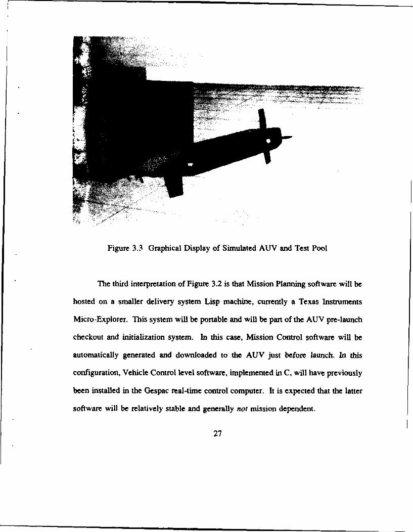
Figure 3.3 Graphical Display of Simulated AUV and Test Pool
The third interpretation of Figure 3.2 is that Mission Planning software will be
hosted on a smaller delivery system Lisp machine, currently a Texas Instruments
Micro-Explorer. This system will be portable and will be part of the AUV pre-launch
checkout and initialization system. In this case, Mission Control software will be
automatically generated and downloaded to the AUV just before launch. In this
configuration, Vehicle Control level software, implemented in C, will have previously
been installed in the Gespac real-time control computer. It is expected that the latter
software will be relatively stable and generally not mission dependent.
27
At the time of this writing, only the first interpretation of the software system
for the Model 2 AUV is fully operational. Moreover, much remains to be done to
further expand this system to better support meaningful AUV operations. In parallel
with this activity, work is also under way to realize the second and third
interpretations. This thesis, however, is confined to the Mission Planning software at
the Mission Planning level.
D. MISSIONS
The Defense Advanced Research Projects Agency (DARPA) has identified over
70 military missions especially suited for AUV execution [Ref. 2, 20]. The current
stage of development of the system considers only a minute subset of these, and
classifies them under four categories: routine, charting, covert, and intelligence
missions. Further, although multi-task missions are common, this study assumes only
single-task missions with the following generic three-phase structure: transit from start
to a goal location, perform task upon reaching destination, an,' then return to the start
location. The high-level mission specifications considered are: available planning time,
mission depth, mission threat level (stealth requirement), and mission range (computer
resource requirements). Other constraints implicit in all missions include obstacle
clearance and collision avoidance.
In order to validate the performance of the expert system and the path-search
strategies, a generic test mission template, called Transit Pool, has been defined in
which the area of operation is the proposed test site for the actual vehicle, namely, the
NPS swimming pool. Given the start and goal locations in the pool and the mission
specification, this mission requires the system to construct a detailed path using an
28
appropriate path-search method; the vehicle is then required to navigate itself in
accordance to the path derived, and to maneuver around obstacles placed in its path.
However, prior to actual in-water tests, several simulated executions under varying
mission specifications must first be performed using the AUV laboratory testbed.
E. PATH PLANNING ASSUMPTIONS
1. ENVIRONMENT MODEL
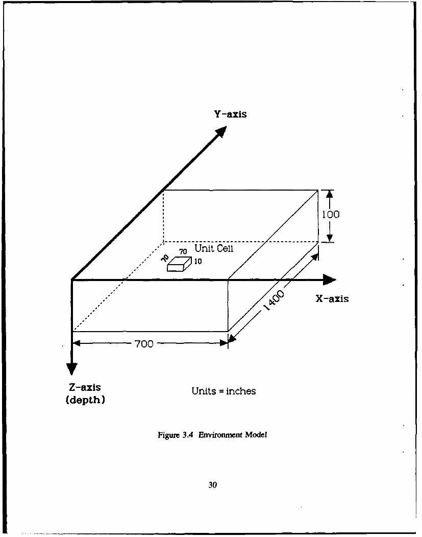
In this study, the environment is the NPS swimming pool. The latter is
modelled by a 3-dimensional Cartesian coordinate system with the X-Y plane parallel
to the surface of the pool and the Z-axis pointing towards increasing depth of pool
(Figure 3.4). Each unit of the X and Y-coordinate is 70 inches (corresponding
approximately to the length of the vehicle), while each unit of the Z-coordinate is 10
inches (corresponding approximately to the height of the vehicle). Henceforth, the
units shall be referred to as the grid units, and the coordinate system as the path-
planning coordinate system, the grid system or simply the grid.
hi this model, a three-dimensional unit cell with unit length on all sides
is defined. Note that this cell is not a cube because one unit Z-coordinate is shorter
than one unit X or Y-coordinate. This then becomes the resolution of the environment
as all locations are resolved to a unit cell at the specified (x,y,z) coordinate.
Another assumption is that the underwater environment is homogeneous
all round; that is, changes in pressure, temperature, density and viscosity of fluid,
which affect the resistance to vehicle movement are not modelled. Thus, the energy
cost per unit distance is constant everywhere in the environment. Note, however, that
29
Y-axis
100" /'" 70 Unit Cell100
,P X-axis
- 4 700
Z-axis Units = inches(depth)
Figure 3.4 Environment Model
30
the cost rate for vertical movements and that for horizontal movements may still be
different, since these are vehicle-related rather than environment-related constraints.
2. OBSTACLE MODEL
Only static obstacles are modelled, although the heuristic search
algorithm can be extended to handle dynamic obstacles [Ref. 8]. The smallest size of
an obstacle is a unit cell, and larger objects are approximated by a lego-style assembly
of multiple unit cells.
One problem inherent in vehicle dynamics which is addressed in the
obstacle model is that there is always a finite distance required to bring a moving
vehicle to a halt, as well as some finite radial distance associated with any vehicle
turns. For instance, it would not be realistic to expect the vehicle to head straight for
an object and then make a sharp dive or turn without hitting it. To circumvent the
problem, a concept called obstacle-growing is adopted [Ref. 211. The obstacle-growing
process increases the size of the obstacles by one unit cell all round its periphery.
Thus a virtual obstacle is created which is larger than the real obstacle. In the
subsequent discussions and figures shown, real obstacles are implied, unless explicitly
stated.
3. VEHICLE MODEL
The following conceptual model of the vehicle is assumed:
1. The size of the vehicle is approximately the unit cell size of the
environment.
2. The vehicle remembers all the places it has visited.
31
3. It expends a certain amount of energy whenever it moves from its
current location to a new position.
4. It tracks its own position with absolute accuracy.
4. SENSOR MODEL
This sensor model is not applicable to A* and Best-first search methods,
since they require complete a priori information. For Heuristic search, the sensors must
facilitate the building of a model of its immediate surrounding environment. More
accurately, it is assumed that the onboard vehicle sensors are able to sense the
surrounding environment defined by a rectangular boxed region with dimensions (5
x 5 x 5) grid units, with the vehicle at the center. Note that it would not be sufficient
for the dimensions to be (3 x 3 x 3) grid units; this is because the vehicle must be able
to sense at least two grid units all around itself in order to detect a virtual obstacle.
F. SIMULATION FACILITIES
As mentioned in Chapter I, a laboratory testbed environment has been
developed as a result of previous thesis work. This testbed is configured from three
separate systems: a Symbolics 3675 LISP machine, a Symbolics Color Monitor and
a Silicon Graphics IRIS 4D/70GT graphics workstation. The LISP machine together
with the Symbolics Color Monitor is set up as the Mission Planning Workstation; the
former hosts the Mission Planning software, while the latter is used to display the
derived path (as well as the actual path during execution phase) in two-dimensional
plan and side-elevation views of the NPS pool. The IRIS graphics workstation is for
3-D visualization of the vehicle and environment during mission execution. The
32
Mission Planning Workstation and the IRIS workstation communicate via an ethernet
network using TCP/IP protocol.
In parallel with the mainstream work of this thesis, the C-code for the IRIS
graphics has been significantly enhanced. First, the code has been modularized to
facilitate easier maintenance in the future. Secondly, the display of the swimming pool
has been modified to reflect the actual Idimensions and, in particular, the tapering
depth of the pool is shown. Thirdly, all objects in the display such as the pool and the
vehicle itself has been converted to an Object File Format (OFF) [Ref. 22], again to
facilitate easier modifications in the future. Lastly, the new NPS Model 2 AUV has
been added to the display. These changes were necessary not only as an upgrade of
the simulator, but also to bring it on par with the current status of the overall project.
G. SUMMARY
This chapter discusses in detail the problems addressed by this thesis. The
current vehicle characteristics are described; in particular, the planned incremental
realization of its control architecture is highlighted. The basic underlying assumptions
for the development of both the Mission Planning Expert System and the path-search
strategies are also listed and described in detail. They include assumptions concerning
the type of missions considered, the environment and obstacle models, and the vehicle
and the sensor models. Finally, the role of the laboratory testbed used in this thesis is
explained.
33
IV. MISSION PLANNING EXPERT SYSTEM
A. SOFTWARE ARCHITECTURE OVERVIEW
The Mission Planning Expert System (MPES) is physically hosted on a
standalone Symbolics 3675 Lisp machine. Conceptually, it resides at the mission
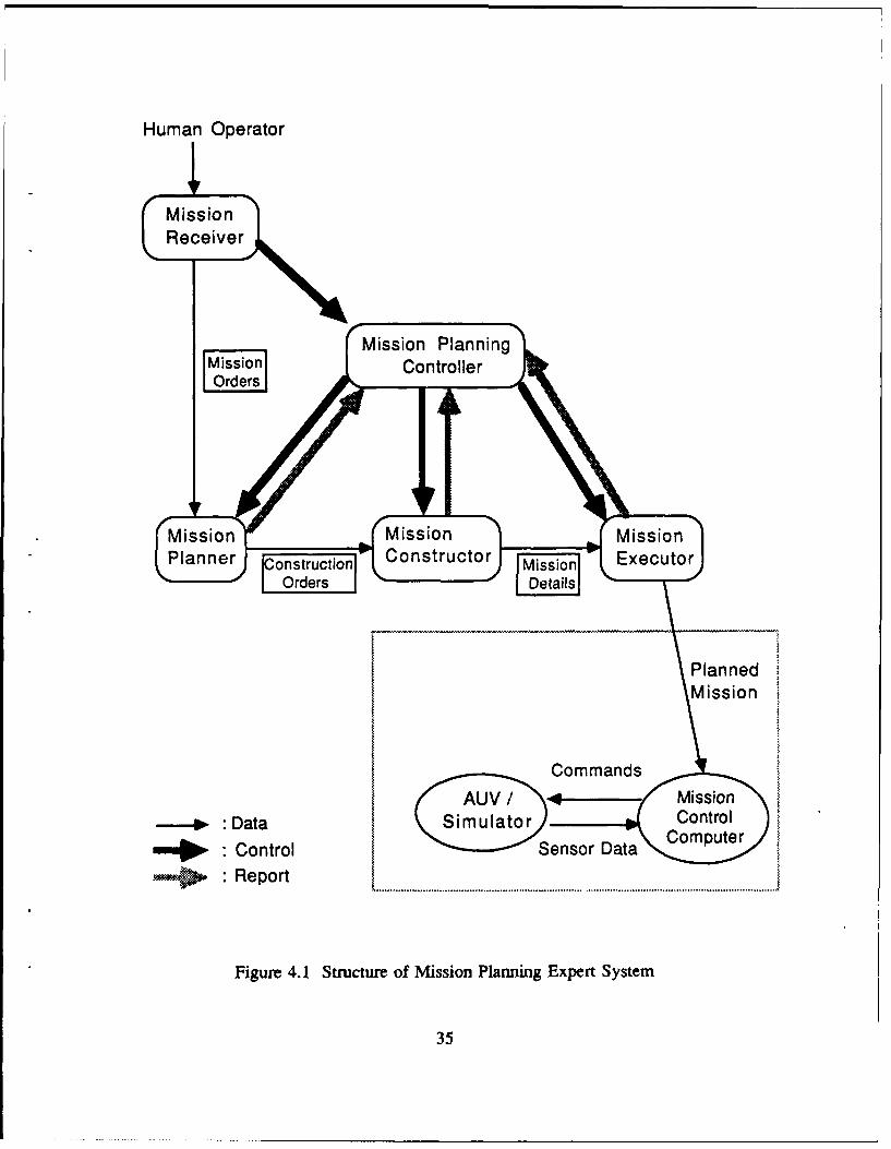
planning level (Figure 3.2). The internal structure of the system, as shown in Figure
4.1, is essentially hierarchical and is patterned after the progressive phases of a
mission, namely, the initiation, planning, construction, and execution phases. The
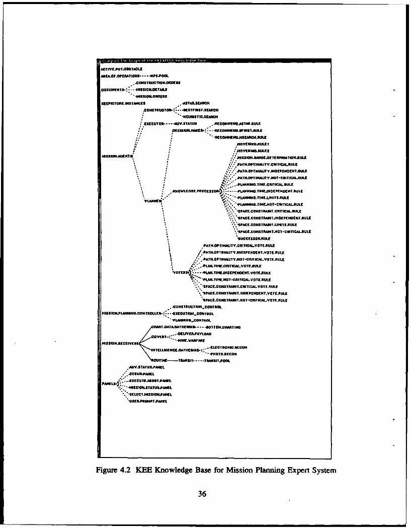
system has been developed entirely in the KEE expert system shell [Ref. 23]; the
corresponding KEE knowledge base is shown in Figure 4.2.
In this architecture, control of the planning operation is centralized at the top-
level Mission Planning Controller (analogous to a real-life Mission Commander) which
is designed to oversee the entire mission and to enforce an orderly transition from one
phase to another. In addition to the Controller, there are four other distinct elements
or role-players in the system corresponding to the four main mission phases. They are
the Mission Receiver, the Mission Planner, the Mission Constructor and the Mission
Executor. Of these, the latter three are charged with the core mission planning and
tasks, and are collectively referred to as the Mission Planning Agents. Communication
between individual elements is effected by means of formal documents realized as
KEE units [Ref. 23].
34
Human Operator
MissionReceiver
Mission PlanningMissCion ControllerOrders .
A-V- 4 -Mission
Dission MissionmuatrionCrontro S DConstructor cuter
Fgurer 4. Stutr fMiso lnig"xetSse
Orders Details
PlannedMission I
Commands/AUn Mission
•:Data SmltrControlDaa Computer
: == "Control Sesor Dt
•: Report
Figure 4.1 Structure of Mission Planning Expert System
35
AC? WLtJT.OSSACtE
AMLP.OPEATICN3- - - NFIPOOL
..CaHSTfflWTIU.aaatKS$
OaCU"EHis 4-- -flSICW.DETAIIJ
KEPICTURL.WSTANCES MSTAR.SEARCH
AXOHSTRJTO'- --- 4ESTFMSTJECH
-4EUNSiIC.SEARI
EXECUIOA- - AU VATATUS .BECaUI!NCASTAK
jIECISWNJIMAKU.---RECOHENDSVUSTSUL.
MOYEING.RULEI
HgSSICMAZNTS HI3ZoftaHOE.ETfHM~IOILRULE
* **' -'PATILOPT*UITY.CRITICALMULE
* *'' PAATHOPTOMIVINDEPENUENTUULE
* * ~. -PATif.OPTIHMTy.HOT-CRITICALRLRUL
* .-FLAMNOAMEA!.RITICAILRULE1.1 IOOLEOa.POCESSONO)": -- ,LMHNOGTIE.I"DIEPENDEMI.AULI
'vLA~m~r;" -PLAHU4a TIHE.UJHfl3.IULIE* FLANION~AMfEMNOT-CRITICALRULE
'SPAC! CONSIAINT.CITICALAULE
SPACL.COHSRMHNT.INOEPENOENT.NULE* SPACE.CONSTRAINT.UHgTSKULIE
* \ SPACL.COHSTAIHT.NOT-CRhICAILSULEVUCCESSON.NULE
hAIH.OPTIHAJTY.CMITALVOTE.RULE
/AH.OPTIHAJT.IHEPENEMT.VOTE.RULEI ,PATH.aPTtHAhUTy.HT-CITCALVOTE.RULE
-PLAWAHIc~NAIIALvoTCAULE
ViR4--- *LAN.TIHE.IHUEPEHCEHT.VOTE.RULE
'UN.T*HEOT-CITICALVOTENULE
"SPACE.COHISIMT.ClITICALVOTE.IlULE
\'SACE.CONSTAINT.IHEPENOENT.VITE.RULE
SPACE.CONSTRADIT.HOT-CKITICAILVOTE.RULE
.. CaNSIRUCTIO-H..oTRatHISSION.PLAMMtO.CONTKOU1IW . -EXECUTISOHCONTROL
-PLfMIOCOHTROL
/HAR.DATA.ATHESUO- ---- 40TTS4.CHARAIINO
MUSSIOH.3ECEIVERtO -- HEN.FAYLEA
\NHTELAIJEENO!.OATHEWRHG. -..- ELEOTROHIO.RECOH14YLUENIEOAHERNC--- 4HOTO.IECOI4
'007iIE-MISIT- TRANSIT.PCOL
MI V.STATUIJPANEL
'..4CUG.PAHEL
FAES#- .4ECUTLAAOSlt.PANEL462SIGI.STAiU.PMIEL
'* SIECT.HISIOf.PMEL
Figure 4.2 KEE Knowledge Base for Mission Planning Expert System
36
The Mission Receiver is solely responsible for interacting with the User
concerning the mission orders (specifications). This is done, during the initiation
phase, via the Mission Planning Workstation described in Section D of tius chapter.
When the orders have been completed, control is passed to the Mission Controller
which then initiates the actions of the Mission Planning Agents. The first of these
agents, the Mission Planner, is a key element in the system; it embodies the essential
"intelligence" or "knowledge" for deciding the most appropriate path-search strategy
to be used, based on the current mission constraints. The Planner's decision is
currently based on three main parameters, the range of the mission (determined from
the start and goal coordinates), the time available for planning the mission, and the
threat level of the mission. The design of the rule-based Planner is described in greater
detail in Section C of this chapter. Once the path-search strategy has been decided, the
decision is registered in the Construction Orders document and passed to the Mission
Constructor.
The Mission Constructor is currently equipped with three search methods or tools,
as shown in Figure 4.2, under the Mission Constructor. They are the A* search,
Best-first search [Ref. 9, 101, and Heuristic search methods, all of which perform
three-dimensional grid-based search. Among these methods, only A* is guaranteed
to produce an optimal path. Best-first search produces generally good (but not always
optimal) paths with less time and space than A*, while heuristic search provides only
37
reasonable paths, but does so very quickly. These generalizations are justified based
on the results of a series of tests conducted to evaluate their performance (described
in Chapter VI).
Upon initiation by the Controller, the Mission Constructor proceeds to construct
the detailed path using the selected search method and the off-line environmental
database. In this process, it ensures that all operational requirements with regard to
threat avoidance, operating depth, etc., as well as any restrictions in vehicle motion,
are considered. The output from the Constructor is the Mission Details document
containing the low-level execution details of the mission. Currently, it contains the
path definition (which is a series of way-points in the path) and the activity to be
performed upon reaching the target/goal location. This document is passed to the
Mission Executor for the next stage of the mission - the execution phase.
The role of the Mission Executor is to interface between the MPES at the
Planning level and the on-board computers at the Mission Control level. In actual
missions, it downloads the planned Mission Details to the AUV for execution, when
commanded by the Controller. In the laboratory setup, however, it is designed to drive
the AUV simulator running on the SGI graphics workstation; that is, it emulates the
Mission Control level function by monitoring and controlling the simulated vehicle as
it navigates along the prescribed path.
38
B. REPRESENTATION OVERVIEW
As mentioned, the MPES is implemented using the KEE expert system shell.
Thus, the five distinct role-players in the system as well as the three documents shown
in Figure 4.1, are implemented as KEE units. A KEE unit is a basic entity in the KEE
environment. It is a block of Lisp code similar to an instantiation of a Common Lisp
class [Ref. 24], but with added functionality. Specifically, unit slots in KEE can hold
procedures (or functions) called methods, and not just attributes or components as in
Common Lisp. This feature of KEE produces a more explicit encapsulation of methods
with objects than is provided for by CLOS, the Common Lisp object standard [Ref.
25].
KEE units which make use of methods in their slots are procedural or method-
based units. KEE units, however, can also be rule-based; these are units that contain
rules rather than methods. Rule-based units are employed for functions which are not
suited for an algorithmic solution. Planning, for instance, is a rather unstructured and
poorly understood problem -- and in particular, mission planning. The same is true for
a generalized mission controller which makes decisions based on dynamically
changing situations; for instance, decisions to skip a mission phase, or to abort the
current mission phase in order to begin re-planning due to unforseen circumstances -
such decisions usually involve a great deal of judgement, and the reasoning and
analysis process is generally unstructured. Employing rule-based reasoning in these
39
areas also facilitates understanding by human experts. For these reasons, the Mission
Planning Agent and the Mission Controller are implemented as rule-based units.
On the other hand, the Mission Receiver, Constructor and Executor are
implemented as method-based KEE units because they execute well-defined tasks with
completely defimed input and output. They possess slots containing procedures which
perform their tasks. Lastly, the three documents are simple units with slots meant only
for data storage.
C. THE MISSION PLANNER
The central role of the Mission Planner agent is to decide which of the available
search methods would best fulfill the given mission requirements. In order to reach
this decision, it works with three specialists: the Knowledge Processor, the Voters, and
the Decision Maker, which are realized as three different rule sets operating under the
Mission Planner. The Mission Planner controls the operations of these three
specialists by providing information to and receiving processed information from them
sequentially.
The interactions between the planner and the specialists are shown in Figure 4.3.
First, the Mission Planner makes the Mission Orders available to the Knowledge
Processor and initiates its operation. The latter processes the high-level information
and transforms them to "intermediate knowledge" that is readily understood by the
40
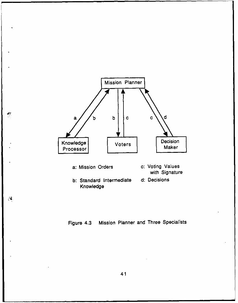
Mission Pln e
" a b b i01c c d
Knowledge Voters DcsoProcessor Maker
a: Mission Orders c: Voting Valueswith Signature
b: Standard Intermediate d: DecisionsKnowledge
Figure 4.3 Mission Planner and Three Specialists
41
Voters. When this processing is completed, the Mission Planner receives the
"intermediate knowledge" from the Knowledge Processor and passes it to the Voters.
The Voters correspond to the intermediate knowledge - each Voter provides voting
values to the search methods according to its strength or weakness in the relevant area
of the path-search process. Upon receipt of the voting values from the Voters, the
Mission Planner initiates the operation of the Decision Maker. The Decision Maker
then makes a decision based on the voting values and the "credibility" of the
individual voters, and sends its decision to the Mission Planner. Finally, the Mission
Planner generates the Construction Orders on the basis of that decision. The following
sub-sections describe the implementation of the three specialists in greater detail.
1. THE KNOWLEDGE PROCESSOR
As its name suggests, the Knowledge Processor processes knowledge -
specifically, it transforms the high-level information contained in the Mission Orders
to "intermediate knowledge" that is understood by the Voters. Intermediate knowledge
here, refers to the degree of criticality associated with the factors pertinent to path
planning, such as the time and space constraints, and the optimality of the path
required. The transformation is done in two stages: first, it processes the Mission
Orders, and then it generates the intermediate knowledge on the basis of the first step.
A total of 15 rules are used - three for the first stage and the rest for the second stage.
42
a. Processing the Mission Orders
The following three rules are used to first process the Mission Orders:
"Mission.Range.Rule", "Space.Constraint.Limits.Rule", and "Plan-
ning.Time.Limits.Rule". The first of these three rules is responsible for estimating the
mission range (or distance). This estimate is needed in order to determine the
computing memory space and time needed for the whole mission, even though an
exact mission distance is not available before completing a path to the goal. Thus, a
gross estimate is obtained by simply taking the horizontal straight-line distance
between the start and the goal positions before planning a path.
The second, the "Space.Constraint.Limits.Rule", determines the upper limits
and the lower limits for computer memory space requirements. This information is
used to determine whether the currently available computer space is sufficient to plan
a mission. Because the greatest requirement for computer space is generated by the
Mission Constructor, the overall space requirements are based entirely on its needs.
Moreover, since the Constructor has three search methods at its disposal, the most
complex of these, A*[6], is used to estimate the needed space. Based on experiments
with the Constructor, the branching factor for A* search averages 1.45, and
approximately 14 units of storage are needed at each node of the search tree.
Consequently, the estimated space requirement (ESR) for A* search is given by
ESR = 14 * (1.4 5 ) D (4.1)
where D is the mission distance measured in grid units. Since this relationship is
43
approximate, before the value for ESR is used by the mission planner, it is
transformed into an upper and lower bound as follows:
UESR = 2 *ESR (4.2)
LESR = 0.5 * ESR (4.3)
The "Planning.Time.Liinits.Rule" performs a task similar to
"Space.Constraint.Limits.Rule". This rule calculates ETR (Estimated Time
Requirement) using the following equation:
ETR = 2.3 * 10 -3 (2 . 1 ) D (4.4)
This equation is derived from the observation that search time is proportional to the
size of the search tree, and that the size of the tree is mainly determined by the
maximum width of the tree. Thus, the same type of equation as that for ESR is
introduced to calculate ETR, and the effective branching factor, 2. 1, is again measured
from experiments. As for space constraints, the value obtained from Eq. 4.4 is
transformed into lower and upper bounds by multiplying by a factor of 0.5 and 2.0
respectively.
b. Generating Intermediate Knowledge
The upper and the lower bounds on time set by this calculation are used by
the "Planning.Time.Critical.Rule", "Planning.Time.Not-Critical.Rule", and
"Planning.Time.Independent.Rule". Depending on the available time given through
the Mission Orders, one of these rules is fired. If the available time is less than the
44
lower bound, then the "Planning.Time.Critical.Rule" is fired. In this case, "Planning
time is critical", a standard form of intermediate knowledge, is given to the Mission
Planner. This is actually done by saving "critical" into the "planning-time" slot of the
Mission Planner unit. If the available time is larger than the upper bound, then the
"Planning.Time.Independent.Rule" is fired, and the value "independent" is saved into
the "planning-time" slot. Otherwise, the "Planning.Time.Not-Critical.Rule" is fired, and
this rule puts "not-critical" into the "planning-time" slot.
Similarly, the "Space.Constraint.Critical.Rule", "Space.Con-
straint.Not-Critical.Rule", and "Space.Constraint.Independent.Rule" utilize the upper
and lower bounds on space to generate the standard intermediate knowledge about the
space constraint. Depending on the comparison result, the value "critical",
"not-critical", or "independent" is saved into the "space-constraint" slot of the Mission
Planner.
The rules relating to path optimality, "Path.Optimality.Critical.Rule",
"Path.Optimality.Not-Critical.Rule", and "Path.Optimality.Independent.Rule", generate
the intermediate knowledge for the Voters from the threat information in the Mission
Orders. Depending on whether the threat level is hostile, neutral, or friendly, the
"path-optimality" slot of the Mission Planner is set to "critical", "not-critical", or
"independent", respectively.
45
The "Successor.Rule" checks the mission threat level and, when the threat
is hostile, puts "shallow successor not allowed" into the "successor-mode" slot of the
Mission Planner in order to keep the Mission Constructor from considering a shallower
path segment than the mission depth during path construction. However, this successor
information is not part of the intermediate knowledge and is moved directly to the
Construction Orders by the Mission Planner when the planning phase is completed.
Two rules relating to the AUV hovering mode, "Hovering.Rulel" and
"Hovering.Rule2", put a proper value into the "vertical-successor" slot of the Mission
Planner depending on the information as to whether the hovering mode is allowed or
not as specified by the user through the Mission Orders. Like the successor
information set by the "Successor.Rule", the "vertical-successor" slot information is
directly transferred to the Construction Orders without further processing.
2. THE VOTERS
The Voters, another of tiuee specialists under the Mission Planner, mimic
a group of people casting ballots based on their own judgements. As shown in Figure
4.2, nine voting rules are implemented. Those voting rules which match with the
intermediate knowledge generate favor values, which lie in the interval 0 to 1. The
Voters also append their "signatures" to the "favor" values so that the credibility or the
importance of the "favor" values can be weighted by the Decision Maker, the last
specialist under the Mission Planner. Each rule is composed of one condition in the
46
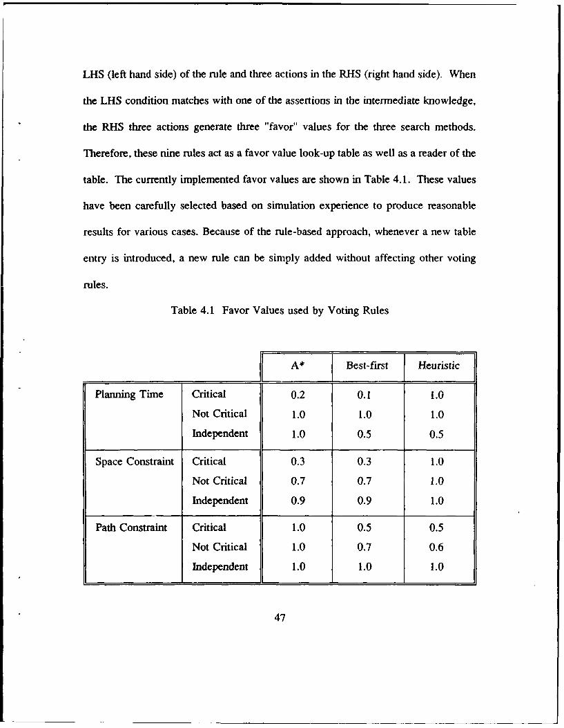
LHS (left hand side) of the rule and three actions in the RHS (right hand side). When
the LHS condition matches with one of the assertions in the intermediate knowledge,
the RHS three actions generate three "favor" values for the three search methods.
Therefore, these nine rules act as a favor value look-up table as well as a reader of the
table. The currently implemented favor values are shown in Table 4.1. These values
have been carefully selected based on simulation experience to produce reasonable
results for various cases. Because of the rule-based approach, whenever a new table
entry is introduced, a new rule can be simply added without affecting other voting
rules.
Table 4.1 Favor Values used by Voting Rules
A* Best-first Heuristic
Planning Time Critical 0.2 0.1 1.0
Not Critical 1.0 1.0 1.0
Independent 1.0 0.5 0.5
Space Constraint Critical 0.3 0.3 1.0
Not Critical 0.7 0.7 1.0
Independent 0.9 0.9 1.0
Path Constraint Critical 1.0 0.5 0.5
Not Critical 1.0 0.7 0.6
Independent 1.0 1.0 1.0
47
3. THE DECISION MAKER
The Decision Maker, the last specialist under the Mission Planner, makes
a recommendation using the favor values. It can discriminate among favor values
based on the signatures provided with them. Currently, no favor values are weighted
differently because the Decision Maker works satisfactorily without different weighting
factors. When the operation of the Decision Maker is initiated by the Mission Planner,
the Decision Maker calculates its own final scores of three search tools by adding up
the favor values. After the final scores are calculated, three rules become active to
select the search tool which gets the highest final score. Basically, the three rules
oppose each other until the highest score is set by the rule which matches with the
highest score among them. The LHS rule compares the score of a specific search tool
and the highest score which is in temporary storage in the Decision Maker. If the
matched score is higher than the highest score in the Decision Maker, then the RHS
rule changes the highest score to the matched score and declares the search tool as the
winner. Therefore, when rule firing is terminated, the highest score as well as the
winner is recorded in the Mission Planner unit. Because of this approach, when an
additional search tool is added into the Mission Constructor, another rule can be
simply added without modifying the existing rules. Note that although this decision
making is internally performed in two phases in the Decision Maker, the Mission
Planner simply sends one message, "Start" to the Decision Maker. The method
(procedure) execution and the rule firings are sequentially performed by the Decision
Maker itself.
48
D. MISSION PLANNING WORKSTATION
1. PURPOSE AND DESIGN CONSIDERATIONS
The Mission Planning Workstation is configured using a Symbolics 3675
LISP machine and an external Symbolics Color Monitor, as mentioned in Chapter III.
Its purpose is to provide the user with an interactive, easy-to-operate, display
workstation from which to plan and monitor the progress of a mission. This is
achieved through the provision of several image panels for:
1. Selecting a mission.
2. Entering the parameters and data for the selected mission.
3. Pre-viewing the detailed plans for the mission and, in particular, the
path.
4. Monitoring the current mission status and the AUV operating status
during execution.
Except for (3), all the panels are developed on the LISP machine using the
KEE graphics facility. In order to produce an easy-to-operate system, two principles
were observed in the design: firstly, the user is prompted at each step, and secondly,
in order to avoid "information overload", all data that is irrelevant to a specific phase
of the mission is either inhibited from display or hidden. A preview of the detailed
plans is facilitated by the display of a two-dimensional representation of the path on
the Symbolics Color Monitor.
49
2. AN ILLUSTRATIVE EXAMPLE
This section takes the reader through the process of planning a simulated
mission. The system begins with an initial screen on the Lisp machine, as shown in
Figure 4.4, which contains two image panels - the User Prompt Panel and the Select
Mission Panel. The former displays the current action to be taken by the human
mission planner (the user), while the latter provides a menu of possible AUV missions.
At startup, the user is required to respond to a select mission prompt with a mouse
click on the designated mission. The currently available choices are shown in Figure
4.4. At present, only the transit pool mission is fully developed, and this mission is
thus used as an example.
After selecting the mission type, the user is presented with a mission specific
panel with initially unknown parameters. In this example, as shown in Figure 4.5, a
Transit Mission panel is displayed and the user is prompted to enter mission parameter
values. Figure 4.5 shows the result of such a selection. In this case, the test pool
selected is the NPS swimming pool. An environmental database for this pool,
including possible obstacles, is encoded as another KEE unit as shown on Figure 4.2.
As can be seen on Figure 4.5, in addition to providing numerical mission parameters,
the user must inform the expert system regarding the threat level and also enable or
disable hovering mode in the AUV. The reason for the latter choice is that, while
hovering mode allows very precise maneuvering, it is very expensive in terms of
50
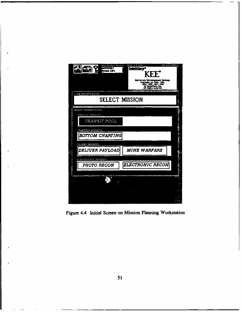
-- __.----.-.SELECT MISSION
IB07TOM CHARTING i
I[DELIVER PAYLOADI[I MINE WARVALRZ
Figure 4.4 Initial Screen on Mission Planning Workstation
51
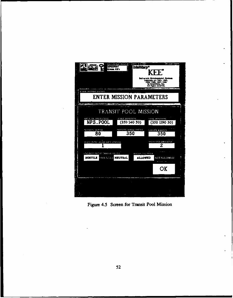
II
501etwam Dmwekt Sri&=
tC" 1 9N 14 4 ,tqr
ENTER MISSION PARAMETERS
PS. POOL (350 140 50) (350 1190 50)
R I 1 1) ,ALLOWEDO
Figure 4.5 Screen for Transit Pool Mission
52
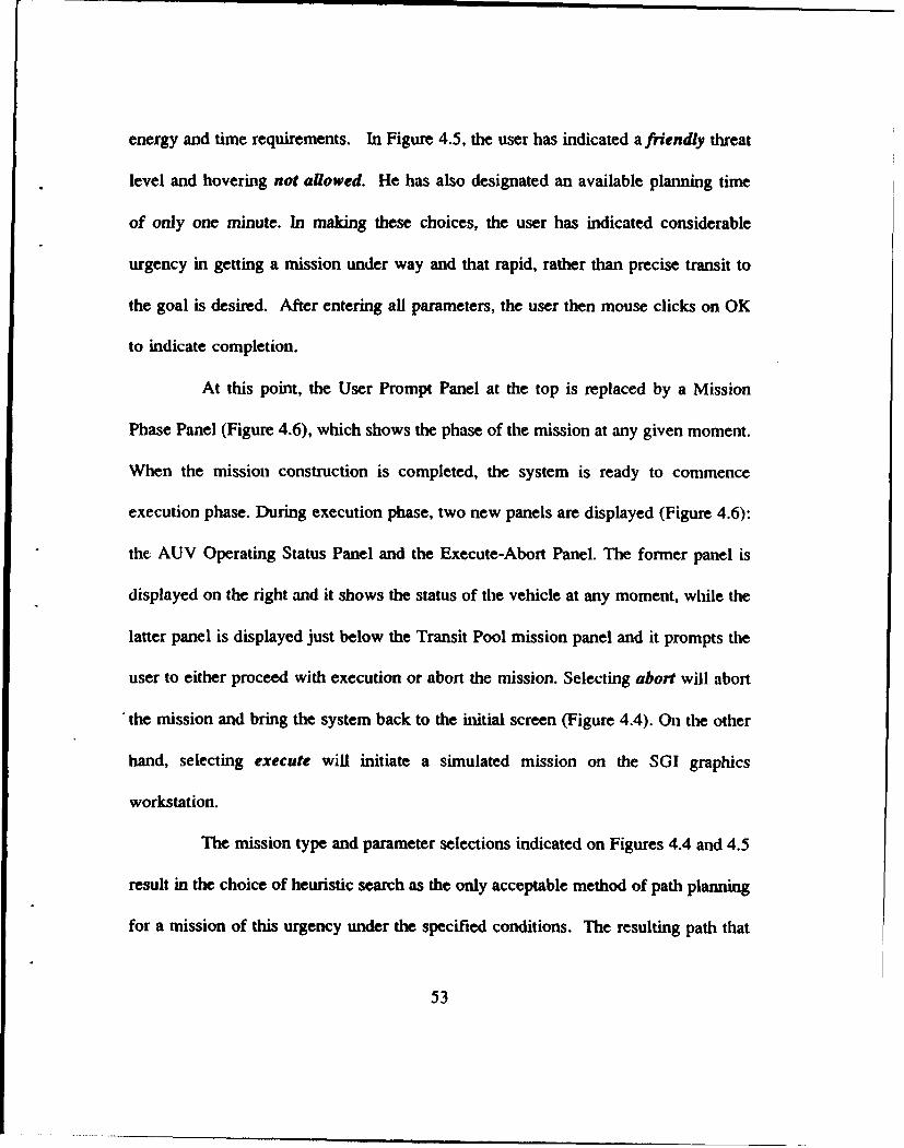
energy and time requirements. In Figure 4.5, the user has indicated a friendly threat
level and hovering not allowed. He has also designated an available planning time
of only one minute. In making these choices, the user has indicated considerable
urgency in getting a mission under way and that rapid, rather than precise transit to
the goal is desired. After entering all parameters, the user then mouse clicks on OK
to indicate completion.
At this point, the User Prompt Panel at the top is replaced by a Mission
Phase Panel (Figure 4.6), which shows the phase of the mission at any given moment.
When the mission construction is completed, the system is ready to commence
execution phase. During execution phase, two new panels are displayed (Figure 4.6):
the AUV Operating Status Panel and the Execute-Abort Panel. The former panel is
displayed on the right and it shows the status of the vehicle at any moment, while the
latter panel is displayed just below the Transit Pool mission panel and it prompts the
user to either proceed with execution or abort the mission. Selecting abort will abort
the mission and bring the system back to the initial screen (Figure 4.4). On the other
hand, selecting execute will initiate a simulated mission on the SGI graphics
workstation.
The mission type and parameter selections indicated on Figures 4.4 and 4.5
result in the choice of heuristic search as the only acceptable method of path planning
for a mission of this urgency under the specified conditions. The resulting path that
53
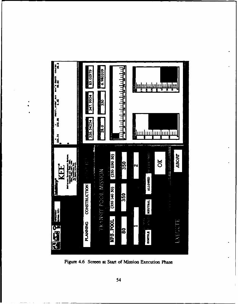
.... I...IC
ii _ _ _
AM C otag
Figure 4.6 Screen at Start of Mission Execution Phase
54
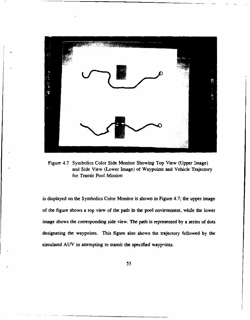
Figure 4.7 Symbolics Color Side Monitor Showing Top View (Upper image)and Side View (Lower Image) of Waypoints and Vehicle Trajectoryfor Transit Pool Mission
is displayed on the Symbolics Color Monitor is shown in Figure 4.7; the upper image
of the figure shows a top view of the path in the pool environment, while the lower
image shows the corresponding side view. The path is represented by a series of dots
designating the waypoints. This figure also shows the trajectory followed by the
simulated AUV in attempting to transit the specified wayp'ints.
55
It should be noted that while the prohibition on the use of thrusters by the
human mission planner prevents the AUV from passing through all waypoints, it does
successfully reach the specified goal. In accomplishing this task, the navigator shown
on Fig. 3.2 used an extremely simple scheme in which desired speed and heading are
derived by simply aiming the vehicle at the next waypoint until it enters the proximity
of tbe selected waypoint. The proximity criterion used is a spherical region of radius
one grid unit around the waypoint. At that time, the navigator switches to the next
waypoint and calculates a new course and speed. Of course, other navigation/guidance
methods enable more accurate transiting of waypoints [Ref. 27, 28, 29], but since
precise path following is not required in the specified transit mission, the above
described simpler approach was used.
It should be observed from Figure 4.7 that the path selected by heuristic
search is not optimal; a shorter path results from simply going around the obstacle at
the prescribed mission depth. Indeed, the use of A* search would yield this path.
However, for the pool size used in this experiment, A* search requires approximately
20 minutes and, as shown on Figure 4.5, in this instance the human mission planner
was unwilling to allow this much time for path planning. As a side remark relating
to Figure 4.7, one of the features of the heuristic search method used in this research,
is that when an obstacle is encountered in a friendly environment, the path planner
follows a rising trajectory while trying to go around the obstacle in the hope that a
way over it can be found without going all the way arounu it. This behavior is clearly
evident in the figure.
56
E. SUMMARY
This chapter presents an in-depth description of the Mission Planning Expert
System and its associated Mission Planning and Control Workstation for the NPS
AUV. Its structure, as well as the design and development using the object-oriented
and rule-based paradigm offered by the KEE expert system shell, is also described in
detail. Finally, an example is given that takes the reader through the mission planning
phases using the Mission Planning workstation.
57
V. HEURISTIC SEARCH
A. INTRODUCTION
The Heuristic search method is designed for autonomous vehicles in a cluttered
underwater environment. It is an informed search strategy which provides a semi-
optimizing solution [Ref. 26] to guiding the vehicle to a specified goal location while
maintaining a given transit depth.
As the name suggests, the algorithm is based on heuristics. The specific heuristics
used are meant to closely model human behavior in its reasoning decision-making
concerning which route to take. These heuristics not only provide local cost
optimization decisions but also endow the vehicle with obstacle avoidance and
clearance capabilities required for it to operate autonomously.
The dominant characteristics of this method that set it apart from the traditional
Al search methods such as A* and Best-first are:
1. It does not require the use of an agenda [Ref. 9, 10] of unexplored paths.
2. It makes extensive use of heuristics for path-search as well as for obstacle
clearance.
3. It does not require complete a priori information on the environment.
4. It is capable of dealing with uncharted obstacles.
5. It is relatively much faster.
6. It can be extended to deal with dynamic obstacles.
58
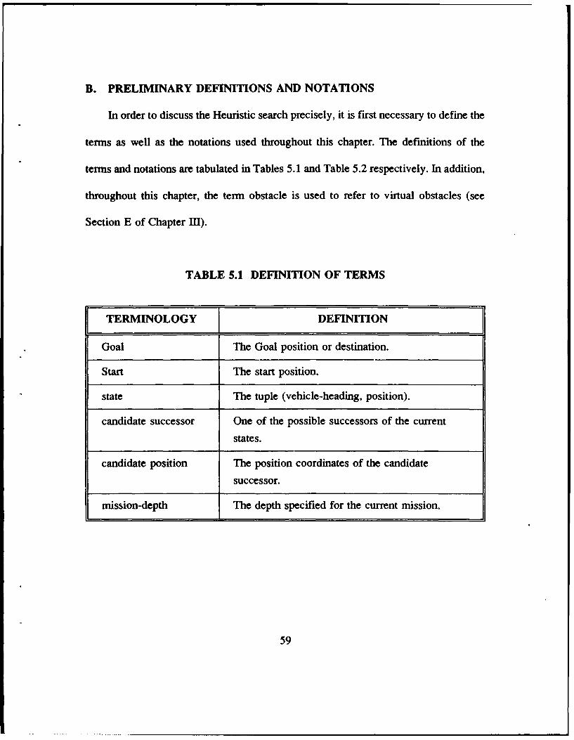
B. PRELIMINARY DEFINITIONS AND NOTATIONS
In order to discuss the Heuristic search precisely, it is first necessary to define the
terms as well as the notations used throughout this chapter. The definitions of the
terms and notations are tabulated in Tables 5.1 and Table 5.2 respectively. In addition,
throughout this chapter, the term obstacle is used to refer to virtual obstacles (see
Section E of Chapter I11).
TABLE 5.1 DEFINITION OF TERMS
TERMINOLOGY DEFINITION
Goal The Goal position or destination.
Start The start position.
state The tuple (vehicle-heading, position).
candidate successor One of the possible successors of the current
states.
candidate position The position coordinates of the candidate
successor.
mission-depth The depth specified for the current mission.
59
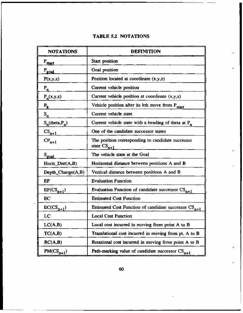
TABLE 5.2 NOTATIONS
NOTATIONS DEFINITION
Pstart Start position
Pgoal Goal position
P(x,y,z) Position located at coordinate (x,y,z)
Pn Current vehicle position
Pn(x,y,z) Current vehicle position at coordinate (x,y,z)
Pk Vehicle position after its kh move from Pstart
Sn Current vehicle state
Sn(theta,Pn) Current vehicle state with a heading of theta at P.
CSn+ 1 One of the candidate successor states
CPn+ 1 The position corresponding to candidate successorstate CSn+ 1
Sgoal The vehicle state at the Goal
HorizDist(A,B) Horizontal distance between positions A and B
DepthChange(A,B) Vertical distance between positions A and B
EF Evaluation Function
EF(CSn+I) Evaluation Function of candidate successor CSn+ 1
EC Estimated Cost Function
EC(CSn+I) Estimated Cost Function of candidate successor CSn+ 1
LC Local Cost Function
LC(A,B) Local cost incurred in moving from point A to B
TC(A,B) Translational cost incurred in moving from pt. A to B
RC(A,B) Rotational cost incurred in moving from point A to B
PM(CSn+1 ) Path-marking value of candidate successor CSn+ 1
60
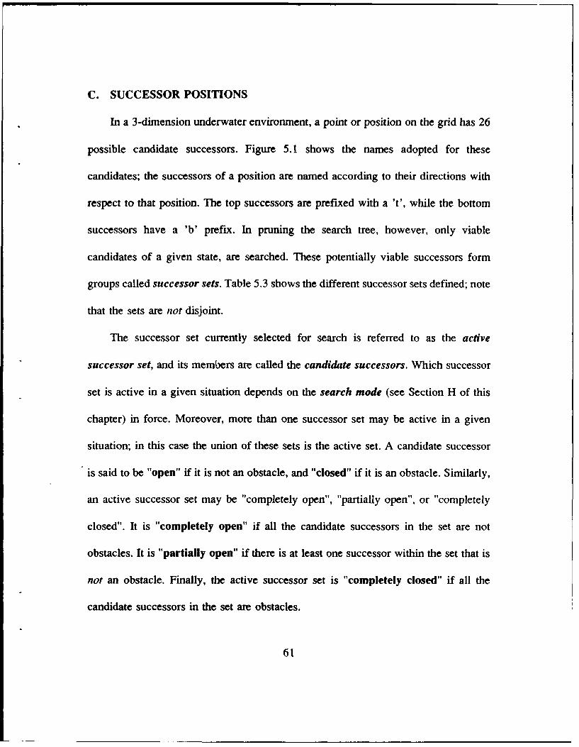
C. SUCCESSOR POSITIONS
In a 3-dimension underwater environment, a point or position on the grid has 26
possible candidate successors. Figure 5.1 shows the names adopted for these
candidates; the successors of a position are named according to their directions with
respect to that position. The top successors are prefixed with a 't', while the bottom
successors have a 'b' prefix. In pruning the search tree, however, only viable
candidates of a given state, are searched. These potentially viable successors form
groups called successor sets. Table 5.3 shows the different successor sets defined; note
that the sets are not disjoint.
The successor set currently selected for search is referred to as the active
successor set, and its members are called the candidhte successors. Which successor
set is active in a given situation depends on the search mode (see Section H of this
chapter) in force. Moreover, more than one successor set may be active in a given
situation; in this case the union of these sets is the active set. A candidate successor
is said to be "open" if it is not an obstacle, and "closed" if it is an obstacle. Similarly,
an active successor set may be "completely open", "partially open", or "completely
closed". It is "completely open" if all the candidate successors in the set are not
obstacles. It is "partially open" if there is at least one successor within the set that is
not an obstacle. Finally, the active successor set is "completely closed" if all the
candidate successors in the set are obstacles.
61
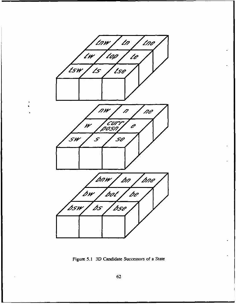
Figure 5.1 3D Candidate Successors of a State
62
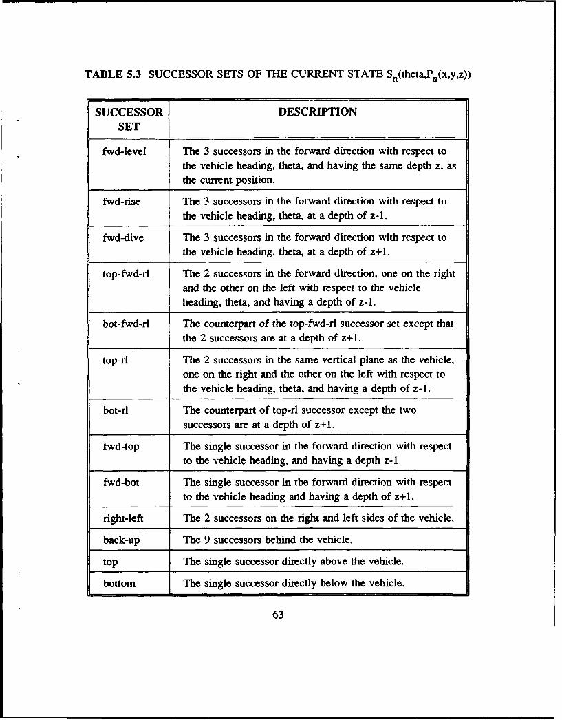
TABLE 5.3 SUCCESSOR SETS OF THE CURRENT STATE Sn(theta,Pn(x,y,z))
SUCCESSOR DESCRIPTIONSET
fwd-level The 3 successors in the forward direction with respect tothe vehicle heading, theta, and having the same depth z, as
the current position.
fwd-rise The 3 successors in the forward direction with respect tothe vehicle heading, theta, at a depth of z-1.
fwd-dive The 3 successors in the forward direction with respect tothe vehicle heading, theta, at a depth of z+l.
top-fwd-rl The 2 successors in the forward direction, one on the rightand the other on the left with respect to the vehicleheading, theta, and having a depth of z-1.
bot-fwd-rl The counterpart of the top-fwd-rl successor set except thatthe 2 successors are at a depth of z+l.
top-rl The 2 successors in the same vertical plane as the vehicle,one on the right and the other on the left with respect tothe vehicle heading, theta, and having a depth of z-1.
bot-rl The counterpart of top-rl successor except the twosuccessors are at a depth of z+l.
fwd-top The single successor in the forward direction with respectto the vehicle heading, and having a depth z-1.
fwd-bot The single successor in the forward direction with respectto the vehicle heading and having a depth of z+l.
right-left The 2 successors on the right and left sides of the vehicle.
back-up The 9 successors behind the vehicle.
top The single successor directly above the vehicle.
bottom The single successor directly below the vehicle.
63
It should also be noted that the successor set of a state is a function of the
heading of that state. For instance, the forward-level successors for a current heading
of 0 degrees is the set [ne, n, nw], while the same for a heading of 90 degrees is [ne,
e, se]. With this dependence on heading, it is more accurate to speak of the successors
of a state rather than the successors of a position. To illustrate the different successor
sets, Figure 5.2 shows an example of the different successor sets for a vehicle heading
of 270 degrees. In addition, the term forward position is used to refer to any successor
set in front of the vehicle. In the example of Figure 5.2, the forward position refers
to one or more of the following sets: the fwd-level, fwd-rise, and fwd-dive successor
sets.
D. HEURISTICS
The heuristics employed offer advice on which set of successors of a state to try
for further search under a given circumstance. Two classes of heuristics are defined -
General heuristics and Obstacle Clearance heuristics. General heuristics are
applicable under all circumstances or modes, providing guidance on the choice of the
best successor position while Obstacle Clearance heuristics suggests a systematic
approach to searching for "a way out" when an obstacle is encountered.
64
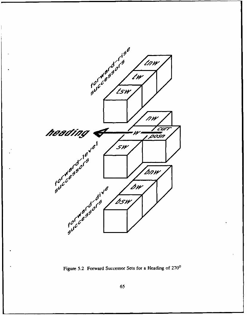
00 ---- 0.--
Figure 5.2 Forward Successor Sets for a Heading of 270°D
65
| |0m
The following general heuristics are adopted:
1. Move toward the goal whenever possible.
2. Prefer to move in the direction of current heading
3. Try not to visit the positions already explored.
4. Keep to the specified mission-depth as far as possible.
5. Search forward successor positions as far as possible.
Obstacle clearance heuristics used are as follows:
6. Prefer to search bottom successors (bottom-search) or top successors (top-
search) as determined by the rule-based system.
7. In either case, prefer to move along the diagonal of the obstacle until it is
cleared.
E. ENERGY COST MEASURE
All paths have an associated cost in terms of the amount of energy expended in
traversing it. The path-planning problem requires finding a reasonable cost (semi-
optimizing) path between the start and the goal positions. Thus, some measure of
energy cost has to be adopted. In this study, the energy cost is normalized to distance
units, which is inches (the unit used to measure the size of the vehicle); this unit shall
be referred to as the normalized energy unit, or simply the energy unit. For example,
suppose the distance between point A and point B on a horizontal plane is 100 inches
then energy expended in moving from A to B is 100 energy units.
66
F. EVALUATION FUNCTION (EF)
Heuristics 1, 2 and 3 require an Evaluation Function to estimate the cost of
moving from a given state to the Goal. At each state, this cost is evaluated for all
candidate successors and the one with the lowest evaluation function is chosen as the
best successor of the current state. Note that the evaluation function does not include
the accumulated cost of moving the vehicle from the Start to its current state. Thus,
unlike A* search which performs "global optimization", heuristic search is guided by
local optimization.
The Evaluation Function has 2 main components:
1. Local Cost (LC) of moving from the current state to a candidate successor
state.
2. Estimated Cost (EC) of moving from the candidate successor state to the Goal
position.
Mathematically, this can be expressed as follows:
EF(CSn+1) = LC(Sn,CSn+1 ) + EC(CSn+1) (5.1)
1. LOCAL COST FUNCTION (LC)
The Local Cost function computes the energy required to move the vehicle
from its current state (S.) to a candidate successor state (CSn+I). It is the sum of two
components:
67
1. Translational Cost to move the vehicle from point P. to CPn+1.
2. Rotational Cost required to change the heading of the vehicle in moving
from Sn to CSn+I.
Mathematically, it is expressed as follows:
LC(SnCSn+1) = TC(Pn,CPn+1) + RC(SnCSn+1 ) (5.2)
a. Translational Cost (TC)
The translational cost is different for horizontal and vertical maneuvers.
Here, it is assumed that the cost rate (i.e., the energy expended per unit distance) for
vertical movement (depth changes) is greater than that for horizontal movement by a
factor of 1.2. For example, suppose the Euclidean distance between point A and point
B is 100 inches; if A and B lie on the same horizontal plane, then energy expended
is 100 inches, whereas, if A and B were in the same vertical plane, the cost would be
120 inches. Formally, the Translational Cost in moving from point A to point B is
defined as follows:
TC(A,B) = HorizDist(A,B) + 1.2 * Depth.Change(A,B) (5.3a)
Thus, in moving from current state Sn to a candidate successor CSn+l,
the translational cost incurred is given by:
TC(Pn,CPn+1 ) = HorizDist(Pn,CPn+1 ) + 1.2 * DepthChange(Pn,CPn+l) (5.3b)
68
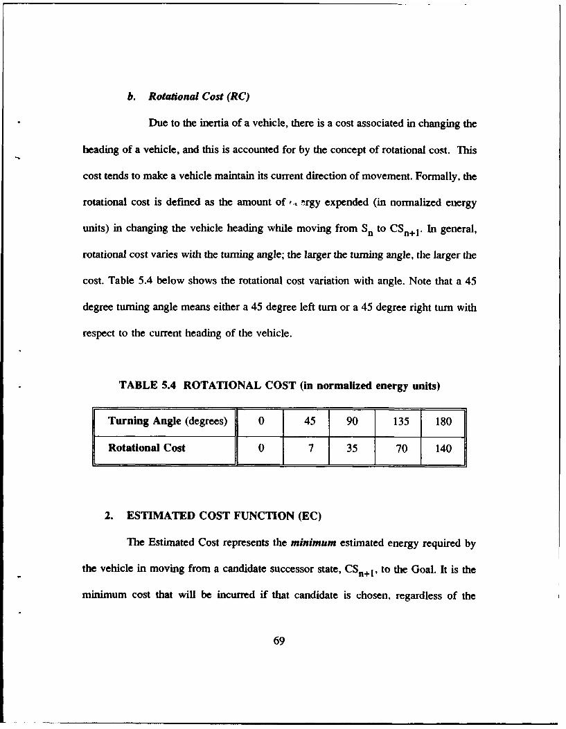
b. Rotational Cost (RC)
Due to the inertia of a vehicle, there is a cost associated in changing the
heading of a vehicle, and this is accounted for by the concept of rotational cost. This
cost tends to make a vehicle maintain its current direction of movement. Formally, the
rotational cost is defined as the amount of t., rgy expended (in normalized energy
units) in changing the vehicle heading while moving from Sn to CSn+ 1* In general,
rotational cost varies with the turning angle; the larger the turning angle, the larger the
cost. Table 5.4 below shows the rotational cost variation with angle. Note that a 45
degree turning angle means either a 45 degree left turn or a 45 degree right turn with
respect to the current heading of the vehicle.
TABLE 5.4 ROTATIONAL COST (in normalized energy units)
Turning Angle (degrees) 0 45 90 135 180
Rotational Cost 0 7 35 70 140
2. ESTIMATED COST FUNCTION (EC)
The Estimated Cost represents the minimum estimated energy required by
the vehicle in moving from a candidate successor state, CSn+1 , to the Goal. It is the
minimum cost that will be incurred if that candidate is chosen, regardless of the
69
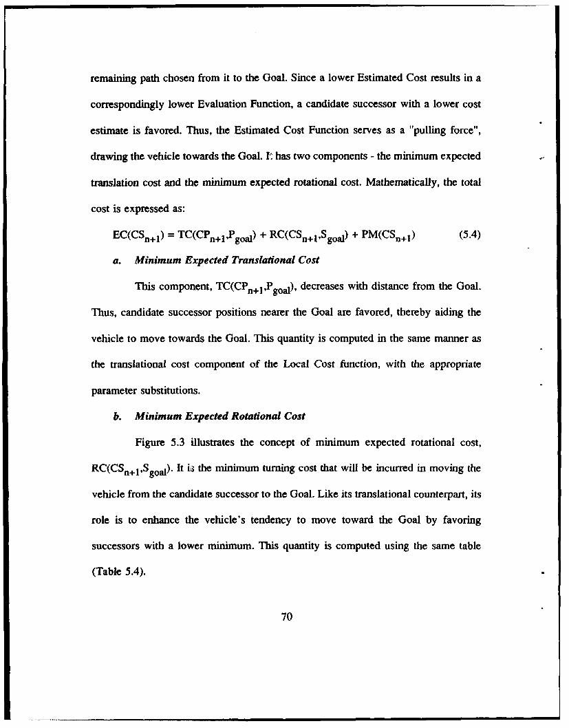
remaining path chosen from it to the Goal. Since a lower Estimated Cost results in a
correspondingly lower Evaluation Function, a candidate successor with a lower cost
estimate is favored. Thus, the Estimated Cost Function serves as a "pulling force",
drawing the vehicle towards the Goal. I has two components - the minimum expected
translation cost and the minimum expected rotational cost. Mathematically, the total
cost is expressed as:
EC(CSn+1 ) = TC(CPn+1 Pgoal) + RC(CSn+l'Sgoal) + PM(CSn+1) (5.4)
a. Minimum Expected Translational Cost
This component, TC(CPn+ l ,P goal) , decreases with distance from the Goal.
Thus, candidate successor positions nearer the Goal are favored, thereby aiding the
vehicle to move towards the Goal. This quantity is computed in the same manner as
the translational cost component of the Local Cost function, with the appropriate
parameter substitutions.
b. Minimum Expected Rotational Cost
Figure 5.3 illustrates the concept of minimum expected rotational cost,
RC(CSn+lSgoal). It is the minimum turning cost that will be incurred in moving the
vehicle from the candidate successor to the Goal. Like its translational counterpart, its
role is to enhance the vehicle's tendency to move toward the Goal by favoring
successors with a lower minimum. This quantity is computed using the same table
(Table 5.4).
70
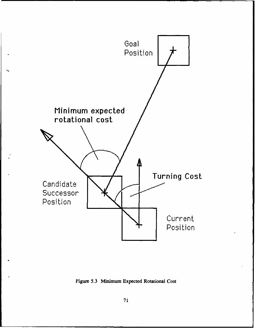
GoalPosition
Minimum expectedrotational cost
Turning CostCandidateSuccessorPosition
CurrentPosition
Figure 5.3 Minimum Expected Rotational Cost
71
c. Path Marking
Path marking [Ref. 8] is a concept introduced to implement the Heuristic 3,
which says "to prefer candidate successor whose positions are not already explored".
It provides a means for the vehicle to "memorize" the positions already visited. The
technique works as follows. The path marking value of each position is initially zero.
Whenever the vehicle moves from state S. to CSn+1 , a path marking value,
PM(CSn+1), equivalent to the Local Cost LC(Sn,CSn+I), is assigned to the position
Pn (corresponding to state S.). This value serves to increase the Evaluation Function
of position P. when it is next evaluated as a candidate successor, thereby reducing its
favorability and its chances of being chosen as the best successor. In this manner,
Heuristic 3 is facilitated.
To summarize the various component costs discussed in this section (Section
F), Figure 5.4 shows the entire cost structure.
G. OBSTACLE CLEARANCE
The obstacle clearance heuristics exploit the fact that obstacles in the real world
are largely high or wide. Odd-shaped obstacles can be approximated by these two
shapes. As shown in Figure 5.5, for high obstacles, the shortest path is to move
horizontally around the obstacle, whereas for wide obstacles, the shortest path is to
move vertically over or under the obstacles. However, without any knowledge of the
72
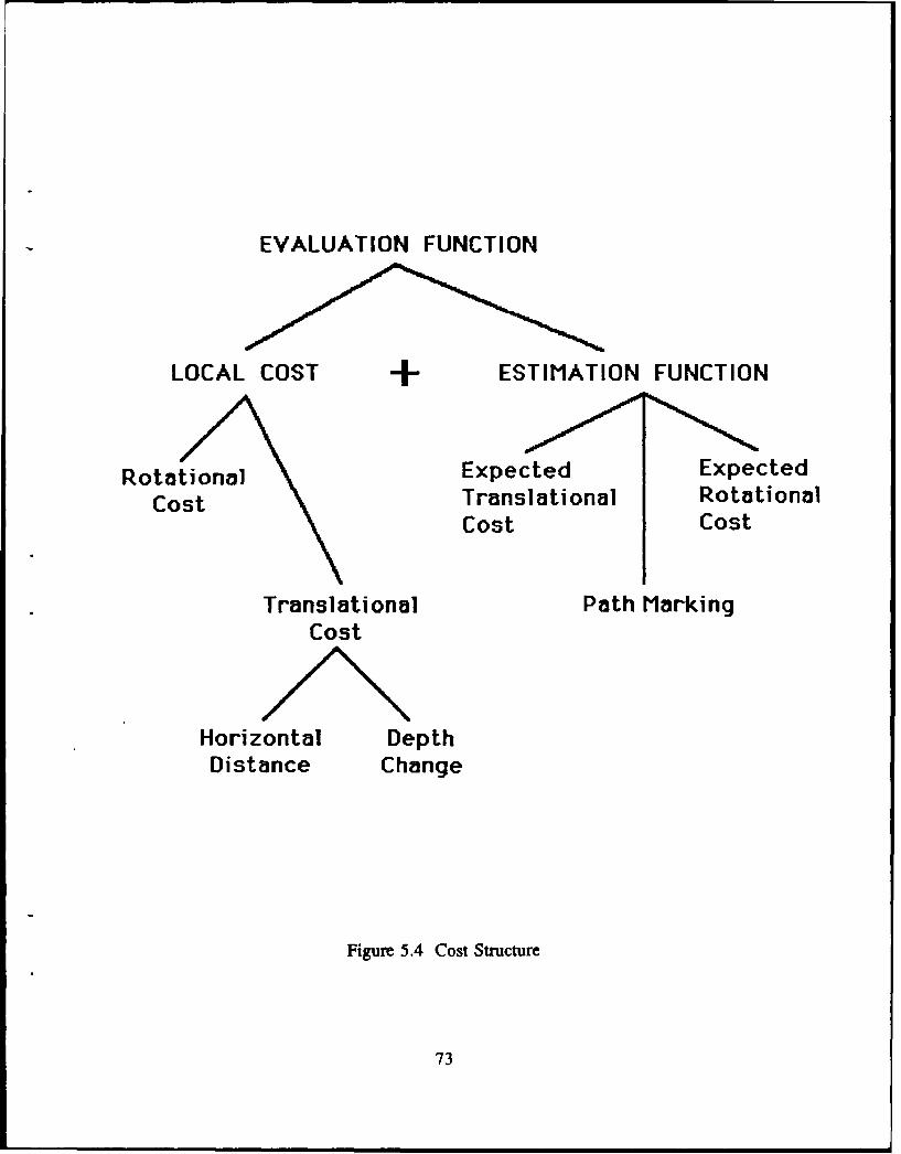
EVALUATION FUNCTION
LOCAL COST + ESTIMATION FUNCTION
Rotational Expected ExpectedCost Translational Rotational
Cost Cost
Translational Path MarkingCost
Horizontal DepthDistance Change
Figure 5.4 Cost Structure
73
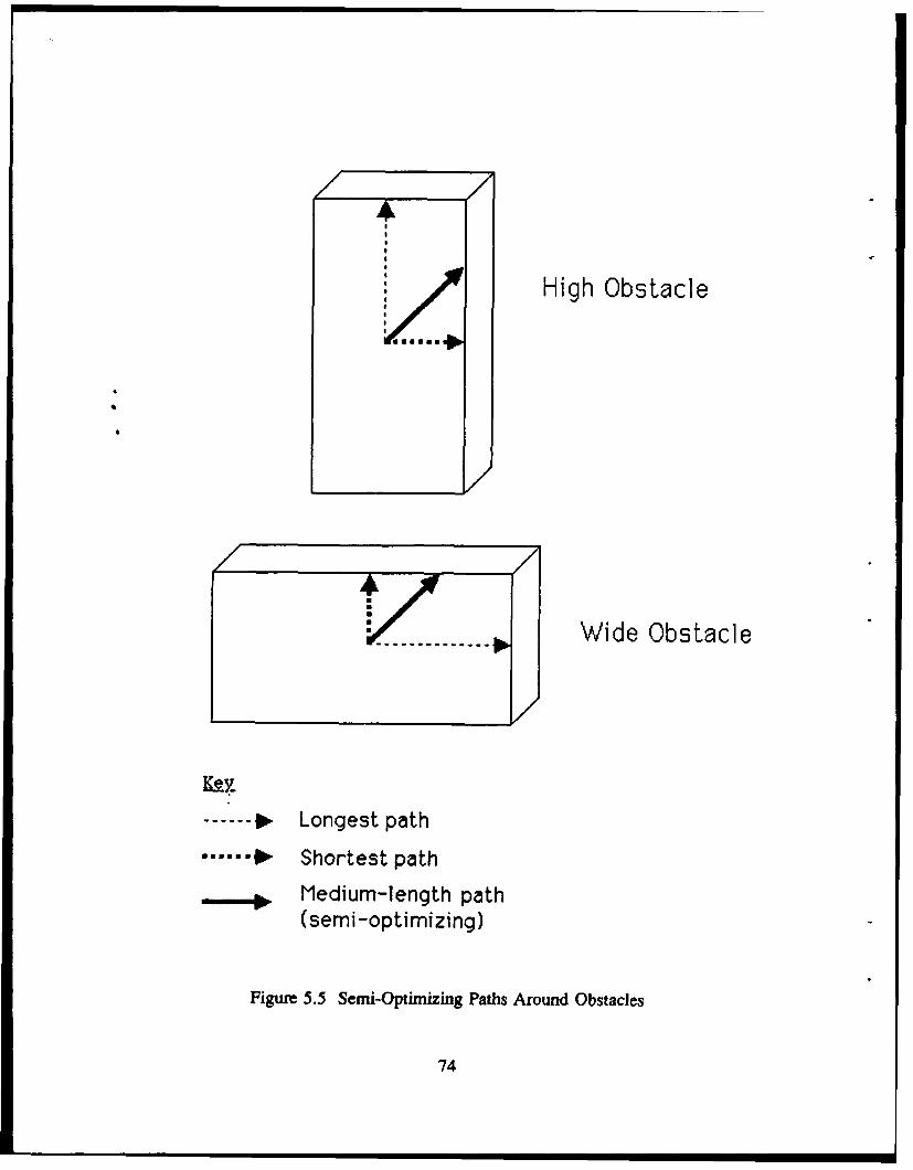
High Obstacle
aat/ ------ Wide Obstacle
------ Longest path... 0- Shortest path
.-. Medium-length path(semi-optimizing)
Figure 5.5 Semi-Optimizing Paths Around Obstacles
74
disposition of the obstacle, it is not possible to determine which way is shortest. A
compromise, semi-optimizing solution is to move along the diagonal of the obstacle,
as illustrated in the figure. Thus, in the absence of any a priori information concerning
the shape and size of the obstacle encountered, a reasonable strategy would be to
move diagonally along the obstacle wall whenever possible. This heuristic is realized
by defining a preferred successor search sequence that constrains the vehicle to do
just that, as explained in the following sections.
H. MODES OF OPERATION
1. OVERVIEW
The heuristic search algorithm defines three ,nodes of operation: NORMAL
mode, OBSTACLE mode, and OBSTACLE-EDGE mode. These modes determine the
heuristics that are called into play. Since the latter also affects the successor sets to
be searched, the modes are also referred to as search modes. Before proceeding
further, it is emphasized again that the term obstacle used in this section refers to
virtual obstacles.
Figure 5.6 shows the mode transition flowchart at a high conceptual level.
The search process begins in the NORMAL mode where only the general heuristics
are employed. It remains in this mode until the vehicle encounters an obstacle
blocking its path. It then changes to OBSTACLE mode and calls upon the obstacle
75
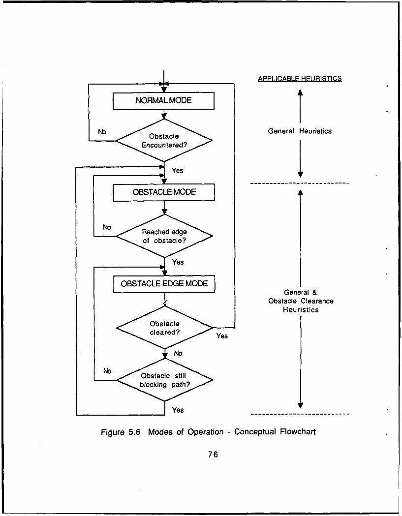
APPLICABLE HEURISTICS
NORMAL MODEI
No Obstacle General Heuristics
OBT EncueedGE MO EGnea>,J Yes
SOBSTACLEG MODE I
OB T C EED EM D General &
Obstacle ClearanceHeuristics
eYes
No- ,sacestl
Figure 5.6 Modes of Operation - Conceptual Flowchart
76
clearance heuristics to guide it. Whenever it reaches an edge of the obstacle, it
progresses to OBSTACLE-EDGE mode. The latter mode is required to confirm that
the obstacle has indeed been cleared. The criteria for this decision is explained shortly.
If confirmation is negative, it returns to OBSTACLE mode; otherwise it switches back
to NORMAL mode. Figure 5.7 shows the corresponding finwchart with the actual
criteria used to determine the mode transitions; note that the right side of the figure
shows the active successor set corresponding to the questions at each stage, in the
chart.
2. NORMAL MODE
In NORMAL mode, only the forward positions of the current state are
searched. The forward positions may be any one of the three successor sets, namely,
the fwd-level, the fwd-rise, and the fwd-dive (see Figure 5.2), depending on the
current vehicle depth with respect to the mission-depth. The fwd-level successor set
is searched (i.e. is active) when the vehicle is at mission-depth, the fwd-rise when its
depth is greater than mission depth, and lastly, the fwd-dive when its depth is less than
the required mission-depth. The system enters OBSTACLE mode if and only if the
currently active successor set is "completely closed", indicating that an object is
blocking its path. Note that in the situation where the active set is "partially open", the
vehicle is not considered to have "encountered" an obstacle (it merely came close to
one); it therefore remains in NORMAL mode.
77
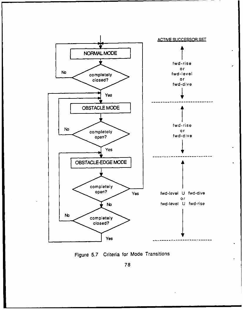
ACTIVE SUCCESSOR SET
NORMAL MODEt
fwd-riseo r
No cmpleelyfwd-Ievelclosedor
fwd-dive
fwd-rise
open >fwd-dive
oeYes fwd-Ievel U fwd-diveor
No fwd-Ievel U fwd-rise
Yes-- - - - - - - - -
Figure 5.7 Criteria for Mode Transitions
78
3. OBSTACLE MODE
When in this mode, the vehicle has sensed an obstacle in its path and
immediately consults the obstacle clearance heuristics for guidance. Here, the active
successor set to be searched is controlled based on a preferred (or prioritized)
sequence list. This list defines the order of the successor sets to be examined in turn
until an "open" successor is found. Such prioritized search is necessary in order to
force the outcome of the search to preferred successor(s) wherever possible. Recall
that according to the obstacle clearance heuristics, it is preferable to move forward,
and along the diagonal of the obstacle.
To realize the obstacle clearance heuristics, two search sequences are
defined, namely, the top-preferred-sequence, and the bottom-preferred-sequence.
Which sequence is used depends on whether bottom search or top search is preferred,
as determined by the rule-based planner. When the threat level is hostile, the bottom-
preferred-sequence is chosen; otherwise, the default top-preferred-sequence is used.
The two sequences are defined as follows:
Top-preferred-sequence:
[fwd-rise fwd-level top-rl fwd-top top
fwd-dive bot-rl fwd-bot right-left backup]
Bottom-preferred-sequence:
[fwd-dive fwd-level bot-rl fwd-bot bottom
fwd-rise top-rl fwd-top right-left backup]
79
The search always begins with thefirst successor set in the sequence chosen.
This is the fwd-rise successor set if the top-preferred sequence is selected, and it is the
fwd-dive set if the bottom-preferred sequence is chosen. This first successor set is used
as the criteria for progressing from OBSTACLE mode to OBSTACLE-EDGE mode.
There are three possible cases: the first successor set is "completely open", "partially
open" or "completely closed".
If the first successor set is "completely open", it is an indication that the
search process has reached an edge of the obstacle, where clearance is possible; in this
case, the system progresses to OBSTACLE-EDGE mode. In fact, this is the only
situation where the system is allowed to move on to OBSTACLE-EDGE mode. It
must be stressed again that this criterion for transiting to OBSTACLE-EDGE mode
from OBSTACLE mode applies only to the first successor set in the sequence, as
shown on the right column of Figure 5.7.
If the first successor set is "partially open", then the best candidate successor
is selected, but the system remains in OBSTACLE mode. Lastly, if it is "completely
closed", the next successor set in the sequence becomes active and is tried. If this set
is also "completely closed", then the next one in line is tried. This continues until an
open candidate successor is found. Like the second case, the system remains in
OBSTACLE mode. It must be stressed that, if the system remains in OBSTACLE
mode, the search in the next cycle will begin again with the first successor set.
80
4. OBSTACLE-EDGE MODE
This is a transitory mode whicb serves to confirm that the obstacle has
indeed been cleared. This mode is necessary to prevent the system from going to
NORMAL mode prematurely, and causing it to return to OBSTACLE mode
immediately because the obstacle is not fully cleared.
When the system enters OBSTACLE-EDGE mode, the vehicle may have
deviated away from the mission depth, considering that it was previously in
OBSTACLE mode, trying to find a way out. Thus, the active successor sets chosen
in OBSTACLE-EDGE mode should attempt to bring the vehicle back to the mission
depth. To achieve this, there are two alternative active successor sets that can be
searched: the first set is the union of fwd-level and fwd-rise successor sets (with no
priority between members of the union), and the second set is the union of fwd-level
and fwd-dive successor sets. Each of these contain six candidate successors. The first
set is used when the current vehicle depth is greater than the mission depth; otherwise
the second set is used. The reason for including the fwd-level successor set in the two
alternatives is to allow the vehicle to move forward horizontally whenever moving
towards the mission depth is not possible.
After the active set (containing six candidates) has been chosen as described,
there are again the usual three possibilities: the set is "completely closed", "partially
open", or "completely closed". If it is "completely closed", then a wall of obstacles is
81
on its path, and it regresses to OBSTACLE mode. Otherwise, if the active set is
"completely open", there is a high chance that the obstacle has been cleared, and it
proceeds to NORMAL mode. Lastly, if the successors are "partially open", then the
obstacle is still in its immediate vicinity; in this case, it chooses the best successor
(according to the general heuristics), but remains in OBSTACLE-EDGE mode.
I. AN ILLUSTRATIVE EXAMPLE
To illustrate the mode transitions during obstacle clearance, consider the example
shown in Figures 5.8a and 5.8b. Figure 5.8b shows the corresponding front, side and
top views of Figure 5.8a. Note that virtual obstacles are shown in the diagrams.
In the situation depicted, the Goal is assumed to be far away on the other side of
the wall (Figure 5.8a), and near the X--O plane. It is also assumed that the system is
in NORMAL mode when the vehicle is at position P1 = P(5,2,4) -- at the mission
depth, z = 4 -- and heading in the direction of the Y-axis. In this state, the active
successor set is the fwd-level set I P(4,3,4), P(5,3,4), P(6,3,4) ). Since this set of
coordinates are all obstacles, it is "completely closed"; thus, the system changes its
mode to OBSTACLE mode, while still at position P1.
Assuming the mission planner decides that top search is preferred, the top-
preferred-sequence is used, and the first successor set in this sequence is fwd-rise.
Since this set is also "completely closed", the next set in the sequence, namely the
82
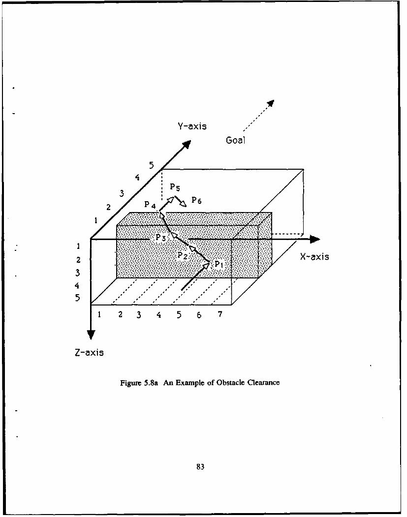
Y-axis S
S
4- 2
Z-axis
Figure 5.8a An Example of Obstacle Clearance
83
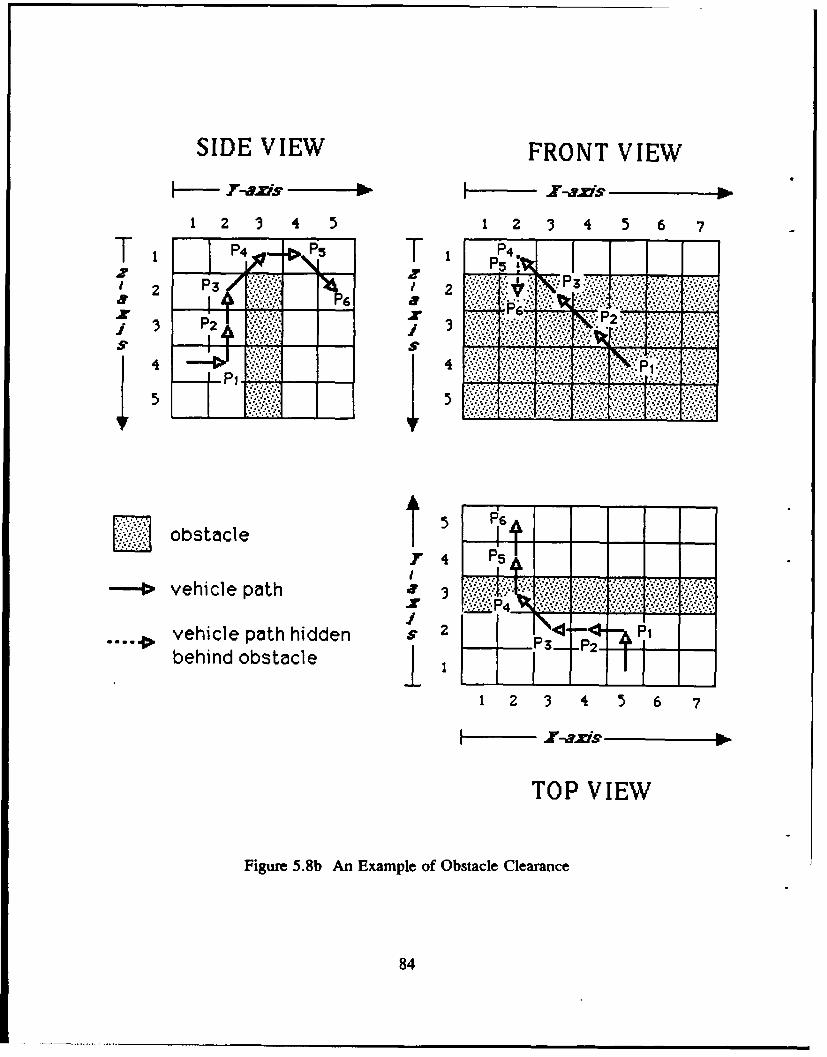
SIDE VIEW FRONT VIEW
To-0 1 P5 T:112 2 P ..2
6 P2......<* r P2
obtal I #PIG
obstaicle pt4
1vehicle path hidden $2 T4 P
behind obstacle I P2-
1 2 3 4 5 6 7
F- r-axis
TOP VIEW
Figure 5.8b An Example of Obstacle Clearance
84
fwd-level is tried. As noted earlier, this set is "completely closed"; so, the next
successor set in the sequence, namely, the top-rl set is searched. This set contains two
candidate successors, P(4,2,3) and P(6,2,3), both of which are "open". Suppose that
P(4,2,3) is selected (by the general heuristics) as the successor; so the best successor
is P2 = P(4,2,3), but the system remains in OBSTACLE mode (since the first
successor set is not "completely open").
Note that the vehicle heading at position P2 has changed to the negative X-axis
direction. With the system still in OBSTACLE mode, the search begins again with the
first successor set of the top-preferred-sequence. At this state, the fwd-rise successor
set is I P(3,1,2), P(3,2,2), P(3,3,2) ). Of these candidate successors, P(3,2,2) is chosen
as the best successor, since P(3,3,2) is an obstacle and P(3,1,2) has a high expected
rotational cost. Thus, the best successor is P3 = P(3,2,2). Here again, the system stays
in OBSTACLE mode because the first successor set is not "completely open".
At position P3, the search commences with the fwd-rise set which is the set
P(2,1,1), P(2,2,1), P(2,3,1) }. Of the three candidates, P(2,3,1) is chosen because it
is nearest to the goal and also. because it has the lowest expected rotational cost.
Hence, P4 = P(2,3,1). This time, the situation has improved; since this first successor
set in the sequence is "completely open", the system can progress to the OBSTACLE-
EDGE mode.
85
Note that in traversing from PI, through P2 and P3, and then to P4, the vehicle
is actually constrained to move diagonally along the obstacle, in accord with the
obstacle clearance heuristics. Moreover, at P4, the vehicle has actually crossed the
edge of the obstacle; hence, the term OBSTACLE-EDGE mode.
When the vehicle reaches position P4, its depth is less than the mission depth
(z=4); so, the active successor set during OBSTACLE-EDGE mode is
fwd-level U fwd-dive
= { P(l,4,1), P(2,4,I), P(3,4,1) I U ( P(1,4,2), P(2,4,2), P(3,4,2)
= { P(l,4,1), P(2,4,1), P(3,4,1), P(1,4,2), P(2,4,2), P(3,4,2) I
Among these, P5 = P(2,4,l) is chosen as the best successor, because the other
candidates would have incurred greater cost by changing either the vehicle depth or
its heading. Further, since this set is "completely open", the system proceeds to
NORMAL mode, signalling that the obstacle has been cleared. From then on, the
NORMAL mode heuristics would constrain the vehicle to move down towards the
mission depth, by continuing to search only the fwd-dive successor set until it reaches
it.
J. SUMMARY
This chapter discusses the methodology of Heuristic search. The algorithm defines
three separate modes of operation, namely, NORMAL, OBSTACLE, and OBSTACLE-
86
EDGE modes, in which different heuristic sets are used to guide the vehicle. Two
classes of heuristics exist: the general heuristics which apply under all three modes,
and the obstacle clearance heuristics which are operative only when obstacles are
encountered during OBSTACLE and OBSTACLE-EDGE modes.
The heuristics serve to prune the otherwise enormous solution space, by selecting
only the viable successor sets for further search, thereby, contributing to its speed and
versatility. Moreover, since the successor sets all lie within a unit cell of the current
vehicle position, the only requirement is for the vehicle sensor to be able detect the
obstacles within its close vicinity; thus, complete a priori information on the
environment is not required in the case that heuristic search is pursued by a physical
agent. Finally, unlike the A* and Best-first search methods, Heuristic search does not
require an agenda of unexplored paths. This results in efficient computer memory
resource usage. The next chapter quantifies its performance relative to the A* and
Best-first search strategies.
87
VI. PATH PLANNING EXPERIMENTAL RESULTS
A. INTRODUCTION
This chapter provides a quantitative evaluation of the relative performance of the
three path search methods: A*, Best-first, and Heuristic search strategies. In order to
highlight the performance of Heuristic search, the paths derived by the three search
strategies under the exact same environmental conditions and obstacles are compared.
B. SCENARIOS
Nine different simulation scenarios in the NPS pool environment are defined and
used for the study. They are tabulated in Table 6.1 and the detailed definition of each
scenario can be found in Appendix A. For each scenario, a different obstacle
arrangement or layout is defined in a rectangular boxed region near the center of the
pool. In all cases, the Start and Goal positions are located on opposite sides of this
obstacle region. The three paths corresponding to the three path-search methods are
then derived assuming top-search is preferred, and their results compared.
Scenario 1 evaluates their performance in a clear uncluttered environment.
Scenario 2 and 3 tests their ability to find a path around simple obstacles. The
remaining scenarios examine their obstacle clearance ability in a randomly cluttered
environment. Hence, in the random scenarios (4a through 4f), increasing obstacle
88
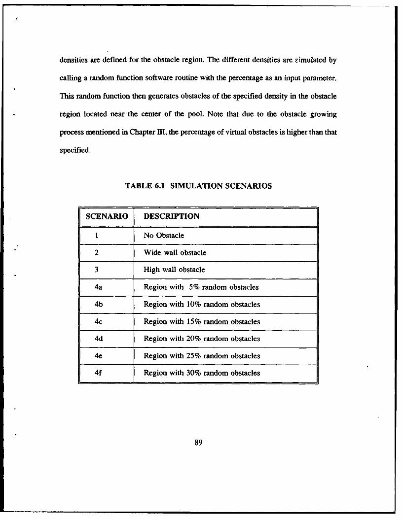
densities are defined for the obstacle region. The different densities are simulated by
calling a random function software routine with the percentage as an input parameter.
This random function then generates obstacles of the specified density in the obstacle
region located near the center of the pool. Note that due to the obstacle growing
process mentioned in Chapter III, the percentage of virtual obstacles is higher than that
specified.
TABLE 6.1 SIMULATION SCENARIOS
SCENARIO DESCRIPTION
1 No Obstacle
2 Wide wall obstacle
3 High wall obstacle
4a Region with 5% random obstacles
4b Region with 10% random obstacles
4c Region with 15% random obstacles
4d Region with 20% random obstacles
4e Region with 25% random obstacles
4f Region with 30% random obstacles
89
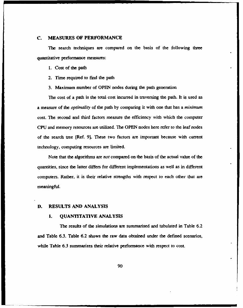
C. MEASURES OF PERFORMANCE
The search techniques are compared on the basis of the following three
quantitative performance measures:
1. Cost of the path
2. Time required to find the path
3. Maximum number of OPEN nodes during the path generation
The cost of a path is the total cost incurred in traversing the path. It is used as
a measure of the optimality of the path by comparing it with one that has a minimum
cost. The second and third factors measure the efficiency with which the computer
CPU and memory resources are utilized. The OPEN nodes here refer to the leaf nodes
of the search tree [Ref. 9]. These two factors are important because with current
technology, computing resources are limited.
Note that the algorithms are not compared on the basis of the actual value of the
quantities, since the latter differs for different implementations as well as in different
computers. Rather, it is their relative strengths with respect to each other that are
meaningful.
D. RESULTS AND ANALYSIS
1. QUANTITATIVE ANALYSIS
The results of the simulations are summarised and tabulated in Table 6.2
and Table 6.3. Table 6.2 shows the raw data obtained under the defined scenarios,
while Table 6.3 summarizes their relative performance with respect to cost.
90
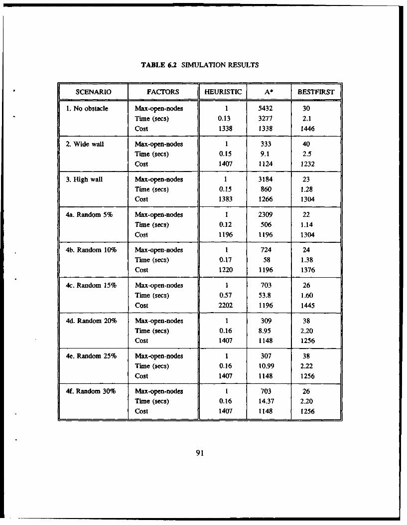
TABLE 6.2 SIMULATION RESULTS
SCENARIO F FACTORS HEURISTIC A* BESTFIRST]
1. No obstacle Max-open-nodes 1 5432 30Time (secs) 0.13 3277 2.1
Cost 1338 1338 1446
2. Wide wall Max-open-nodes 1 333 40Time (secs) 0.15 9.1 2.5Cost 1407 1124 1232
3. High wall Max-open-nodes 1 3184 23Time (secs) 0.15 860 1.28Cost 1383 1266 1304
4a. Random 5% Max-open-nodes 1 2309 22Time (secs) 0.12 506 1.14
Cost 1196 1196 1304
4b. Random 10% Max-open-nodes 1 724 24Time (secs) 0.17 58 1.38Cost 1220 1196 1376
4c. Random 15% Max-open-nodes 1 703 26Time (secs) 0.57 53.8 1.60
Cost 2202 1196 1445
4d. Random 20% Max-open-nodes 1 309 38Time (secs) 0.16 8.95 2.20Cost 1407 1148 1256
4e. Random 25% Max-open-nodes 1 307 38Time (secs) 0.16 10.99 2.22Cost 1407 1148 1256
4f. Random 30% Max-open-nodes 1 703 26Time (scs) 0.16 14.37 2.20
Cost 1407 1148 1256
91
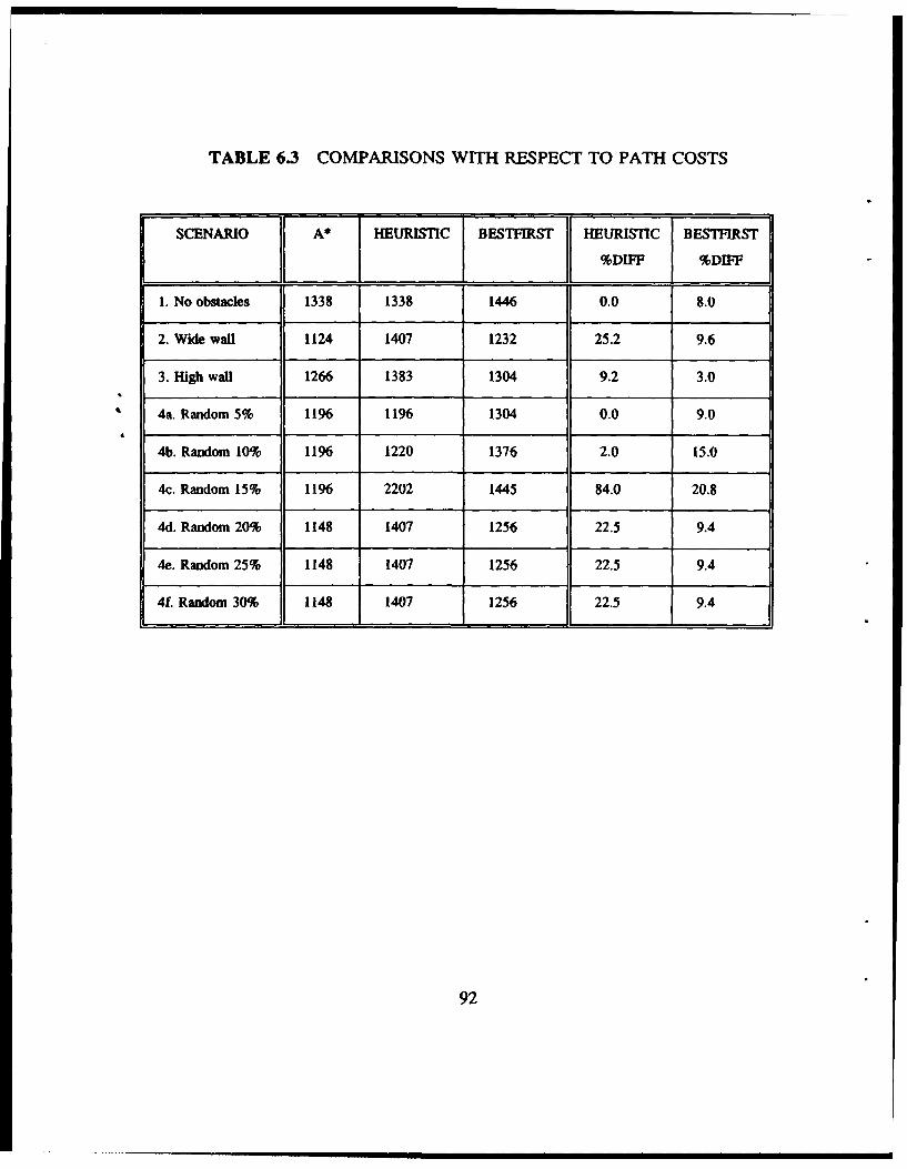
TABLE 6.3 COMPARISONS WITH RESPECT TO PATH COSTS
SCENARIO A* HEURISTIC BESTFIRST HEURISTIC BESTFIRST
%DIFF %DIFF
1. No obstacles 1338 1338 1446 0.0 8.0
2. Wide wal 1124 1407 1232 25.2 9.6
3. High waUl 1266 1383 1304 9.2 3.0
4a. Random 5% 1196 1196 1304 0.0 9.0
4b. Random 10% 1196 1220 1376 2.0 15.0
4c. Random 15% 1196 2202 1445 84.0 20.8
4d. Random 20% 1148 1407 1256 22.5 9.4
4e. Random 25% 1148 1407 1256 22.5 9.4
4f Random 30% 1148 1407 1256 22.5 9.4
92
a. Time Required
This quantity measures the raw CPU time required to find a path. Table
6.2 shows that Heuristic search has excellent time performance. In general, Bestfirst search
takes about 1 order of magnitude longer, while A* is about 2 orders of magnitude longer
than Heuristic search.
b. Maximum Number of Open Nodes
The Heuristic search algorithm has only one OPEN node during the entire
search. This is expected since it does not keep an agenda of open nodes to be explored,
unlike A* and Best-first search strategies; instead an absolute decision is made at each
decision node. This makes Heuristic search highly efficient with reagrd to computer
memory usage. A* lies at the other extreme, requiring enormous amount of storage
(scenario 1 in Table 6.2) even for such short range scenarios.
c. Cost of Path
The optimality of a path can be measured by the percentage cost
difference of its path with respect to the optimal path (i.e. the minimum cost path). In
order to show that the A* search algorithm used in this study yields the optimal path, a
slight digression is necessary.
A search algorithm is said to be admissible if, it always terminates in an
optimal path from the Start location to the Goal location whenever a path from the Start
to the Goal exists. Nilsson [Ref. 9; pp 74 to 79] has shown that in order for the A* search
93
algorithm to be admissible, at any point in the search, the estimated cost of the path from
any point in the path to the Goal (as provided by the estimation function), must be less
than or equal to the actual cost. This condition is clearly satisfied by the Estimation
Function used in this study, since, in fact, the minimum expected cost is used by the
function (and there does not exist any path which will give a lower cost).
Thus, the A* search used in this study gives minimum cost paths (that
satisfy the constraints of the path specifications), and it can therefore be used as the
yardstick for measuring the cost performance of other algorithms.
The second last column of Table 6.3 show that, except for scenario 4c,
the cost of Heuristic search path is usually within 25% of the optimal path. Its cost
performance is optimal or very close to optimal in relatively uncluttered environment
(scenarios 1, 4a and 4b). The reason for the high cost in Scenario 4c (differing from
optimal by 84%) can be explained by analysing its path - a close analysis of Figure 6.6
reveals that the vehicle path was blocked completely by the wall of the pool and, behaving
as a human would, it turned back to find another way through the obstacle. Since
autonomous vehicles usually operate in open environments, this situation is an exception
rather than the norm. The paths obtained for Best-first search also come within 20% of the
optimal solutions as the last column shows.
94
2. QUALITATIVE COMPARISON OF HEURISTIC AND A* PATHS
The paths generated by Heuristic search and A* search for each scenario is
shown in Figures 6.1 through 6.9. It can be seen from Figures 6.1 and 6.4 that in clear and
uncluttered environments, Heuristic search and A* search yield almost the same paths; in
fact, Table 6.2 show that the two paths corresponding to the two methods have the same
cost in each case. The slight deviation in the paths, particularly for Scenario 1 (Figure 6.1),
is probably due to the fact that the sort routine used in A* search does not preserve the
order of the agenda for equal-cost paths. Another contributing factor is that Heuristic
search prefers to maintain the vehicle heading as far as possible, and any required changes
to its heading are therefore deferred till later in the path.
The paths derived by Heuristic search under Scenarios 2 and 3 (see Figures 6.2
and 6.3), exhibit the characteristic behavior induced by obstacle clearance heuristics, as
explained in Sections G and I of Chapter V. In both cases, the Heuristic search path
proceeds diagonally along the wall of the obstacle instead of taking the shortest path as
established by A* search.
Figures 6.5 through 6.9, reveal that Heuristic search and A* search yield
qualitatively very different paths when the environment is increasingly cluttered with
obstacles. This is expected since the fundamental strategy of the two methods are different:
A* search aims for global optimization while Heuristic search aims for local optimization.
It is also noted from Figures 6.7 through 6.9, that as the density of the obstacles increases,
the obstacle region becomes effectively a single contiguous block, and the paths derived
by either method is independent of the obstacle density.
95
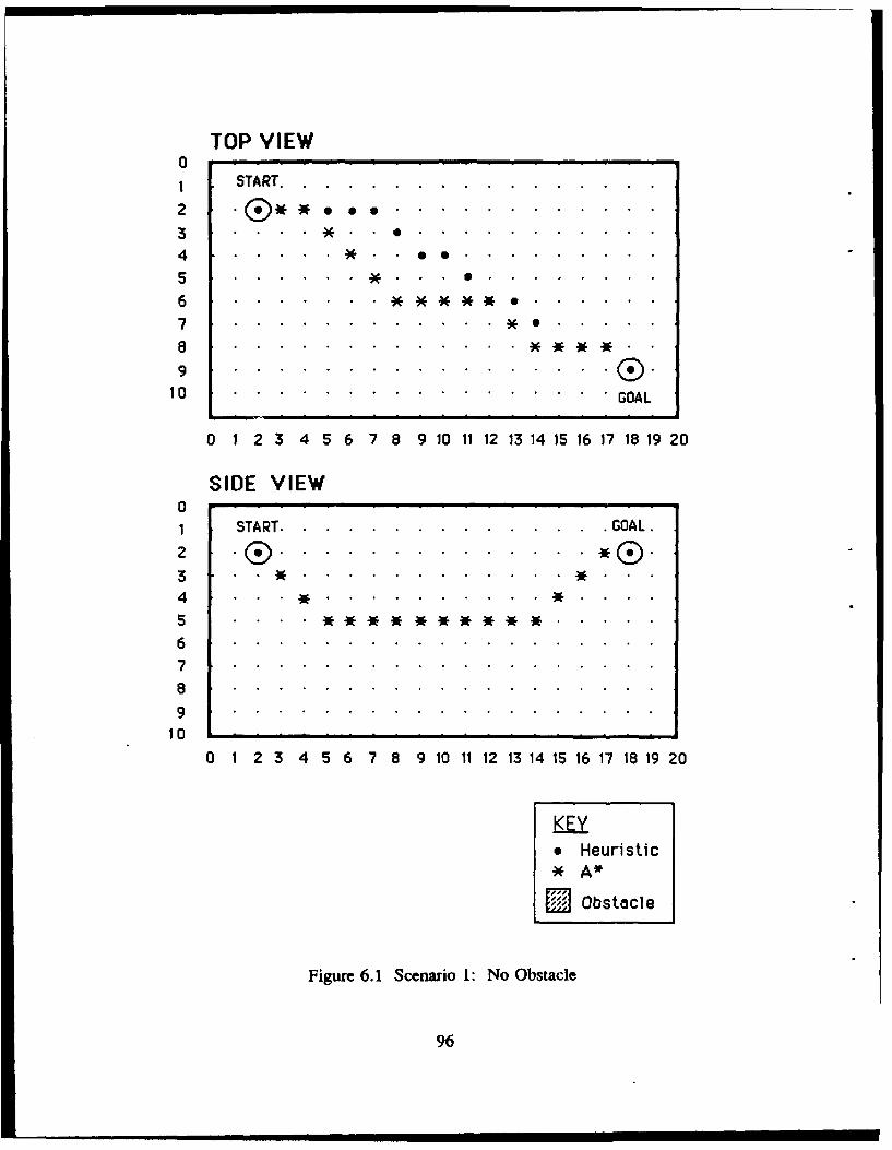
TOP VIEW0I START..................
2 .... .N . . .........
3 *.. ..... . . . ..
4 ". . . . .. . . . ..
6 . .' .7 .. ............. * ...
8 .
9 . . . . . . . . . . . . . . . . .010 . . ............... . GOAL
0 1 2 3 4 5 6 7 8 9 10 11 12 13 14 15 16 17 18 19 20
SIDE VIEW01 START. ............. .GOAL.
2 . . . . ..®
3 * . . . . . . . . . . . .
4 .. ...........5.
67
89
10 . . . . . , . . . . . . . .
0 1 2 3 4 5 6 7 8 9 10 11 12 13 14 15 16 17 18 19 20
KEY* Heuristic
A*
L" Obstacle
Figure 6.1 Scenario l: No Obstacle
96
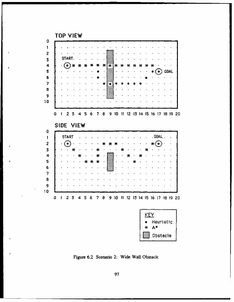
TOP VIEW01 . . . . . . . . . . . .
3 START. . . . . .
4 * * * * *:*(" )* * * * *)( -)-*)
. GOAL
6........... n. . . . .* .
7 ~ ~ ~ ..
8 . . .. . ..29s# . . . . E j . . . . . . .,. .
10 ................... . .. .. ..
O 1 23 45 6 78 9 10 11 12 13141516 17 1819 20
SIDE VIEW01 START............................GOAL
4 . . . . * %
5 . . . .. . . . . .6...
10 - - - - - - - -.
o 1 23 45 6 78 9 101112 1314 1516 1718 192 0
KEY* Heuristic
A4*
Obstacle
Figure 6.2 Scenario 2: Wide WallObstacle
97
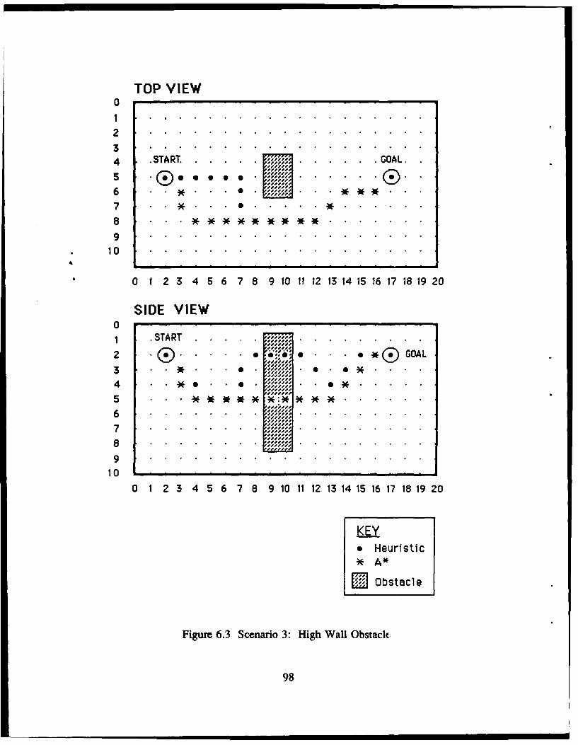
TOP VIEW0
4 .START. GOAL.
7 . . .6...........*... . ..
8 . . * * * * * ............ . .. ...
0 1 2 3 4 56 7 8 9 10 111213 1415 1617 1819 20
SIDE VIEW01 .START. . . . . . . . .
2. . . . .. ~ . GOAL
i 1. . . .,.i,-,-
3 . . . . . . . .*eee . . 6*. . .. . .
4 . . . . . . . 0 .... .. ...
5 . . . .** ** .* *.. .. .. ..10 1 -- I
0 1 2 3 4 5 6 7 8 910 1 1 1314 5 1 17IS 9 2
6E
99
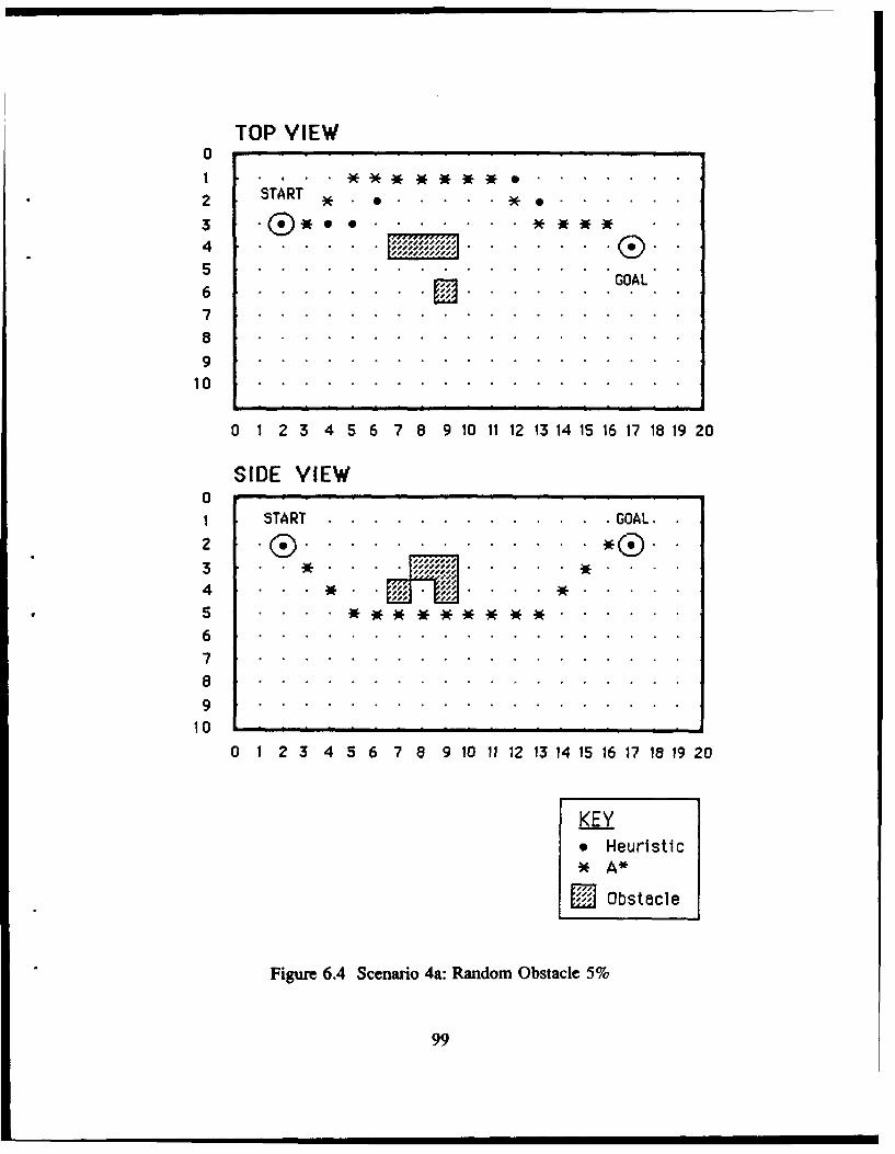
TOP VIEW01 . . . .
2 START* * *. .
3 ...... .. .. .
4......... . . . .jjjjj .
". GOAL
7
89
10
O 1 2 34 56 78 9 1011 12 131415 16 171819 20
SIDE VIEW0 -
1 START.................GOAL.2 . ® . . . . . . . . . . .3 . . . . . . ... . . . . . . . . .
8 . . . . . .. **.*.. .. .. ..
67
89
10 . . . . . . . . . . . . . . . . . . .
10
O 1 23 456 7 8 9 10 11 12 13 14 15 16 17 18 19 20
* Heuristic
SOstacle
Figure 6.4 Scenario 4a: Random Obstacle 5%
99
a . ., . I . . .I
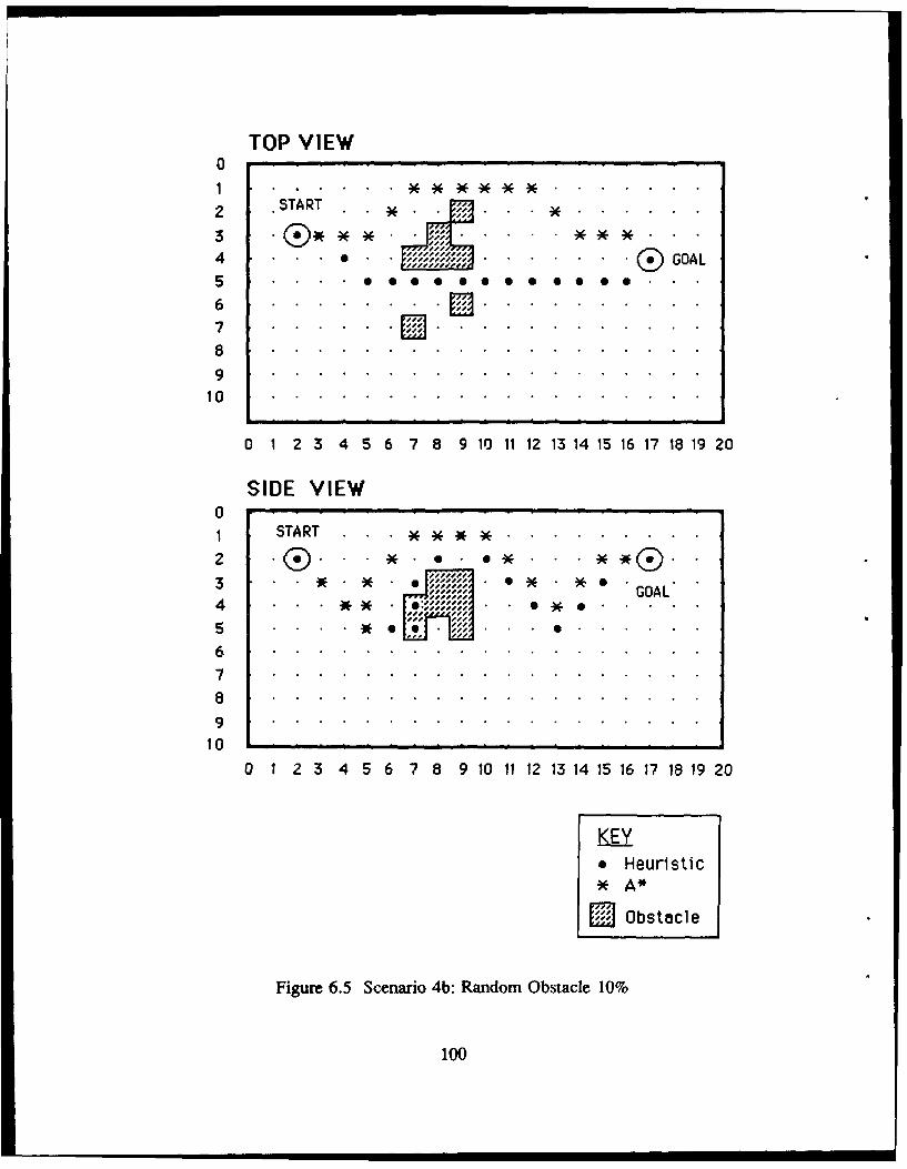
TOP VIEW0
2 *START * ..3 LA.........
4 . . .. . . . . . . GOAL5 . . . . . . . .
89
10
O 1 2 3 4 56 7 8 9 1011 12 131415 1617 1819 20
SIDE VIEW01 START . ................
2 *.e .*..
3 E JI . .. . .
9 * . . . . * ... .. .. ...
67
8
91 0 . . . . . . . . . . . . . . . . . . .
0 1 2 3 4 5 6 7 8 9 10 11 12 13 14 15 16 17 18 19 20
KEY* Heuristic
j Obstacle
Figure 6.5 Scenario 4b: Random Obstacle 10%
100
1 ST R . . . . . . .I
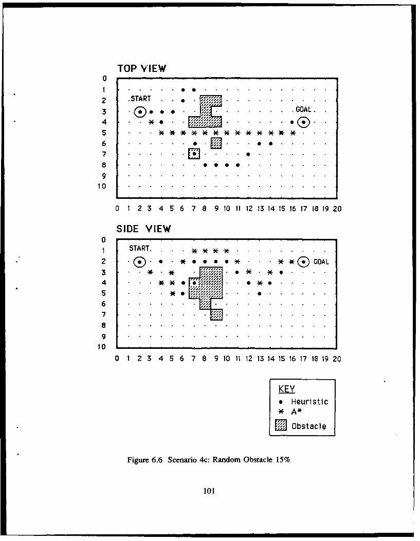
TOP VIEW0
.1 . . .
S .sTART .. . .
6 .. . . . G
8 . ... .. . .*. . a
9
10 9. . . . . . . . . . . . . . . . . .
0 1 2 3 4 5 6 7 8 9 10 11 1 13 14 15 16 17 18 19 20
SIDE VIEW01 START. . . .
2 .. g*• . ** GOAL
3i
3 . . * . * ... 10** *0..
4 . . . . * * . 0%. %%. %%. . 0 *.6 . .
5 . . . . * 0 . . .%% . . . .S
i0 1/js,
89
10 - , . .
0 1 2 3 4 5 6 7 8 9 10 11 12 13 14 15 16 17 18 19 20
KEY* Heuristic
ZObstacle
Figure 6.6 Scenario 4c: Random Obstacle 15%
101
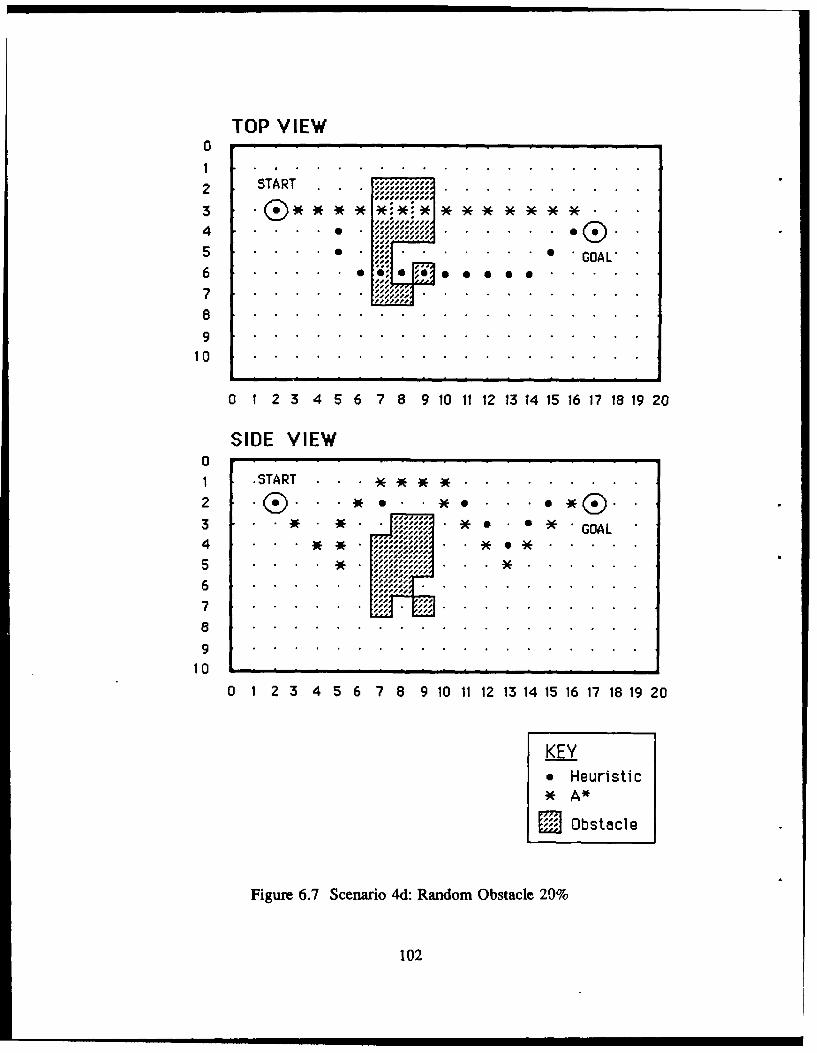
TOP VIEW0
2 START. . . . . . . . . . .
4 . . . . . . ... .. ...
Ile" GOAL'
100
1 .S.A.T . . . .** *.... ... . .. .. .. .2 . .~ . * . . . . . . . . . . .
30. . . . . . . . . . .-- -- .*G O.1 6---
15T . . . . . . . . . . . . .
2---i-
3--'. 6O4 . . .
7
100 1 23 4 56 78 910 1112 1314 1516 1718 192 0
KEY*Heuristic
SObstacle
Figure 6.7 Scenario 4d: Random Obstacle 29%
102
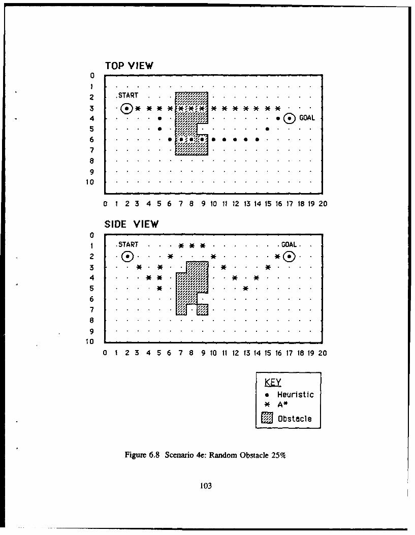
TOP VIEW
0
2 .START . . .. . . . . . . . . .
34 . . . . i GOAL
6 : .Z . .-7 .... ............
910
O 1 2 345 6 78 9 1011 12 1314 1516 17 IS1920
SIDE VIEW
01 .START . . ...... ... ... ... ... ... ... ..... GOAL.-
2 ® .* . .......... f®
3-i-
i-i--i,
-- ,iii'6................., .................... . . .. ... .. ...
100 1 2 3 4 5 6 7 8 9 10 11 12 13 1415 161718 192 0
KEY*Heuristic*A*
Obs tacle
Figure 6.8 Scenario 4e: Random Obstacle 25%
103
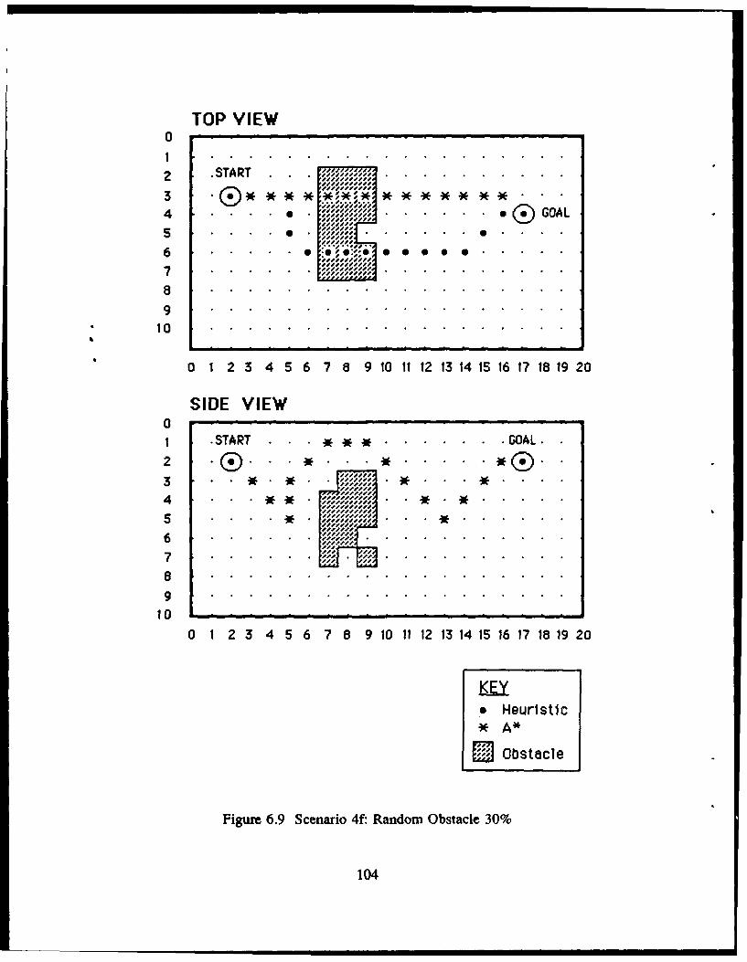
TOP VIEW01
2 .START . . .. . . . . . .
4 . . .. . . . GOAL
5 . . ..............7 . . . .. . ..s. .
610.. . . ... .,, , . . . . .. . GL....SSSS-ii---S
10
1 .START . . . ** ........ GOAL.-2.. . . . ....
edi-eeeS . . . . . . .
i-i-
7.................
89
Figure 6.9 Scenario 4f: Random Obstacle 30%
104
E. SUMMARY
The above results show that Heuristic search is very suitable for autonomous vehicle
path-planning where speed of search and space requirements are fundamental
considerations, and where the optimality of the path with respect to energy cost is not
critical. A* is highly space and time inefficient, but yields an optimal path. The
performance of Best-first search lie somewhere between the two. Qualitatively, Heuristic
and A* strategies yield almost similar paths for clear and relatively uncluttered regions,
and widely different paths for cluttered environments. The most appropriate method to use,
therefore, depends on the given mission, and specifically, on the criticality of the time,
space and cost constraints.
105
VII. SUMMARY AND CONCLUSIONS
A. RESEARCH CONTRIBUTIONS
The research efforts under the NPS-AUV program have, thus far, been directed
at vehicle design at the Vehicle Control level (Figure 3.2) as well as the creation of
the laboratory testbed environment. With the stabilization of the groundwork at this
level, current efforts have begun to examine the issues at the higher Mission Planning
and Mission Control levels. This thesis represents a step in this direction by addressing
the issue of computer support for AUV mission planning. The specific contributions
of this thesis are elaborated in the following sections.
1. A PROTOTYPE MISSION PLANNING EXPERT SYSTEM
The MPES serves as an important mission planning aid to human mission
planners. The Mission Planning workstation developed provides an informative, easy-
to-operate, and a totally interactive control station that allows rapid mission planning
and evaluation of plans prior to actual execution. Additionally, with the prototype
defined and developed, the MPES can be easily upgraded to handle other more
complex missions, as well as providing a basis for experimentation with other rule-
bases.
106
2. SOFTWARE ARCHITECTURE FOR MISSION PLANNING
The software architecture adopted closely models the progressive stages of
mission planning. It represents another approach to designing an expert system which
automatically transforms the high-level mission specifications to detailed low-level
plans. The advantages of this approach are:
1. Simplicity. The complex mission planning task is decomposed into
distinct decision-making entities, thereby simplifying its design and development.
2. Flexibility. The incorporation of a centralized control in the design by
the Mission Planning Controller provides the flexibility needed to react and adapt to
changing situations. This is especially valuable for on-board mission planners and re-
planners which have to respond to unexpected events during the execution of the
mission.
3. Maintainability and ease of enhancements. Future enhancements to
individual entities can be performed with minimum impact to other components. For
instance, modifications to the Voters entity either to consider a new constraint or to
add a new path-search strategy will only require a new entry to Table 4.1. The new
path-search algorithm can also be added to the Mission Constructor with virtually no
side-effects on other entities. This attribute is further augmented by exploiting KEE's
object oriented and rule-based paradigm - the former facilitates modularity and
encapsulation necessary for maintainability, while the latter is suited to the inherently
107
unstructured nature of the problem.
3. DEVELOPMENT AND ANALYSIS OF ALTERNATIVE THREE-
DIMENSIONAL PATH-SEARCH ALGORITHMS
Three path-search strategies, each with differing characteristics were
implemented and their performance compared. The results were used as critical inputs
to the Mission Planning Expert System.
4. HEURISTIC SEARCH STRATEGY
The Heuristic path-search is developed in this thesis promises to be
appropriate for fully autonomous, long-range, high-endurance missions. The speed of
this algorithm and its ability to perform without complete a priori environmental
information also makes it a practical and viable candidate for real-time on-board path
planning functions.
5. GRAPHICAL SIMULATOR UPGRADE
Although it was not intended to be a goal of the research, the code for the
IRIS 4D/70GT graphics workstation was upgraded to be on par with the overall status
of the NPS-AUV project. This was done in order to provide the framework necessary
for more realistic simulations with regard to the test environment and vehicle, prior
to the actual in-water tests.
108
B. RESEARCH EXTENSIONS
There are several broad areas in which future research can be directed. They
include the vehicle design, upgrading of the MPES and the testbed simulator, and the
on-board Mission Control level functions. The near-term goals, however, should bring
about a consolidation of the efforts thus far, and facilitate the construction of a
demonstration prototype AUV. The realization of this prototype will serve not only to
demonstrate that the myriad ideas and design decisions made are coherent and
feasible, but also to uncover early the potential and major design flaws (where they
exist). Thus, the immediate research efforts should emphasize the Mission Control
level functions and the integration of the hardware and software at the Mission Control
and Vehicle Control levels. At the same time, the short and long-term research
objectives should set out the blueprint required to realize a fully autonomous AUV,
suitable for long-range and high-endurance missions. The following sections describe
the possible extensions to four areas: mission planning, mission re-planning, path
planning algorithms, and the graphical simulator.
1. MISSION PLANNING
An immediate task is to develop the code necessary for automatic
downloading of the planned Mission Details to the on-board Gridcase computer, so as
to be ready for the forthcoming in-water demonstration tests. Another near-term goal
would be to expand and develop the other mission types in the same fashion as the
109
one developed for the Transit Pool mission. In the process, other new and probably
more complex constraints may need to be considered - in particular, constraints such
as fuel (energy) requirements and the actual time available for mission execution must
be factored in. The off-line database may also require extension to include more
realistic open ocean environments although this should be done in conjunction with
the upgrades to the graphical simulator to provide the corresponding displays. So far,
the missions considered are relatively simple. Thought should also be given to multi-
task missions which require optimal task scheduling and more sophisticated route
planning capabilities.
2. MISSION RE-PLANNING
A fully autonomous AUV should have the versatility to deviate from
original mission plans and to initiate re-planning in response to changed circumstances.
For instance, if the mission H-hour has been brought forward, it must be able to re-
prioritize and re-plan its tasks in order to achieve the higher mission objectives. Thus,
onboard re-planning and re-scheduling capabilities must be incorporated to enable it
to respond appropriately. A good starting point would be to modify the off-line
mission planning code for the onboard re-planner.
3. PATH PLANNING
Several immediate improvements can be made to the heuristic search
algorithm. Firstly, the various cost figures such as rotational cost and translational cost
110
have been estimated in this study; but, with the development of the actual vehicle,
more realistic vehicle data should be made available and used.
Secondly, although the heuristic search strategy can theoretically perform
without a priori information concerning the environment, it remains to be
demonstrated. However, this would not only require changes to the path-planning code
(mainly the data structures used for encoding the environment), but it also requires the
graphical simulator to be upgraded to simulate processed sonar sensor inputs. The
same is true with its capability to deal with dynamically moving obstacles.
The third possible improvement to Heuristic search is the handling of
concave obstacles. This is related to the path-marking feature used to overcome the
local minimum problem explained in Section F of Chapter V, since all concave
obstacles possess inherent local minimas which may trap the vehicle. Although the
path-marking technique can be used, it is inefficient with respect to cost and time in
the case where the concave obstacle (or "tunnel") is wide and deep. This is due to the
fact that the method has to search almost the entire volume within the concave
obstacle before the path marking value becomes sufficiently high to discourage further
search within the obstacle. Thus, more elegant and more efficient approaches need to
be examined. One promising method that can be explored is the obstacle-marking
technique used in [Ref. 81, for two-dimensional path-planidng.
111
A fourth enhancement to be considered for immediate implementation is
the changes required to be performed on the path search algorithms to accomodate the
hovering mode of the vehicle. Presently, although the interface for its selection is
provided, hovering mode is not considered in the path-search algorithms.
Fifthly, the efficiency of A* search with regard to time and memory
resources, can be improved. Specifically, a different sort method can be explored to
improve the time required to sort the agenda.
In the longer term, one suggestion for consideration relates to the
methodolgy used to realize the heuristics in Heuristic search. Currently, the heuristics
are implemented procedurally for execution speed. Another method is to express the
heuristics in a higher-level rule form, by using Prolog for instance, although this
approach may severely degrade the execution efficiency. Thus, a combination of the
rule-based and procedural approaches may be the most effective way to implement the
heuristics - a technique which is worth exploring.
Within the Mission Planner, one possible and significant enhancement to
the high-level for consideration, is to combine a macro-level route planner with a
micro-level path planner. Thus far, the various computer aided prototypes developed
in the path planning research community, have dealt solely with one or the other.
There is a good possibility, however, for path-planning to be performed in two stages -
first, invoking a route planner to derive the major route segments, and then to plan
the detailed path (for each path segment) using a path planner.
112
A final suggestion is to implement and include new path-search strategies
to expand the suite of path-planning tools available for the Mission Constructor of the
MPES.
4. GRAPHICAL SIMULATOR
The simulator should evolve with the NPS AUV vehicle as well as with the
complexity of the missions it will undertake. As the physical design of the NPS Model
2 AUV stabilizes and becomes more fully defined, its corresponding hydrodynamic
model and maneuvering characteristics should be incorporated on the simulator to
validate its performance prior to actual tests. Another important extension, as
mentioned above, is the display of open ocean environments to support the testing of
more realistic missions. Finally, the simulator can be enhanced to include the
simulation of processed sonar inputs to be passed to path-planning algorithms. In
particular, it can be used to validate the capability of the Heuristic search (and other
search strategies) to plan a path without complete a priori environment information.
113
LIST OF REFERENCES
1. Macpherson, D., A Computer Simulation Study of Rule-Based Control of anAutonomous Underwater Vehicle, Master's Thesis, Naval Postgraduate School,Monterey, CA, June 1988.
2. Nordman, D., A Computer Simulation Study of Mission Planning and Controlfor the NPS Autonomous Underwater Vehicle, Master's Thesis, NavalPostgraduate School, Monterey, CA, June 1989.
3. Crowley, J. L., "Navigation for an Intelligent Mobile Robot," IEEE Journal ofRobotics and Automation, v. RA-I(1), pp. 31-41, 1985.
4. Oommen, B. J. Iyengar, S. S., Rao, S. V. N., and Kashyap, R. L., "RobotNavigation in Unknown Terrains Using Learned Visibility Graphs. Part I: TheDisjoint Convex Obstacle Case," IEEE Journal of Robotics and Automation,v. RA-3(6), pp. 672-681, 1987.
5. Iyenger, S. S., Jorgensen, C. C., Rao, S. V. N., and Weisbin, C. R., "LearnedNavigation Paths for a Robot in Unexplored Terrain," IEEE Computer Society,The Second Conference on Artificial Intelligence Applications, pp. 148-155,1985.
6. Kuan, D. T., Brooks, R. A., Zamiska, J. C., and Das, M., "Automatic PathPlanning for a Mobile Robot Using a Mixed Representation of Free Space,"IEEE Computer Society, Conference on Artificial Intelligence Applications,pp 70-74, 1984.
7. Brooks, R. A., "Solving The Find-Path Problem by Good Rep. -- ntation ofFree Space," IEEE Transactions on Systems, Man, and Cybernetics, v. SMC-13,pp 190-197, 1983.
8. Ok, D. K., A Computer Simulation Study of a Sensor-Based HeuristicNavigation for Three Dimensional Rough Terrain With Obstacles, Master'sThesis, Naval Postgraduate School, Monterey, CA, June 1989.
9. Nilsson, N. J., Principles of Artificial Intelligence, Tioga Publishing Co., 1980.
114
10. Rowe, N. C., Artificial Intelligence Through Prolog, Prentice-Hall, Inc., 1988.
11. Elfes, A., "Sonar-Based Real-World Mapping and Navigation", IEEE Journalof Robotics and Automation, v. RA-3, No. 3, pp 249-265, 1987.
12. Chappell, S. G., "A Blackboard Based System for Context Sensitive MissionPlanning in an Autonomous Vehicle", unpublished technical report, Universityof New Hampshire, Marine Systems Engineering Laboratory.
13. Blidberg, D. R., and Chappell, S. G., "Guidance and Control Architecture forthe EAVE Vehicle," unpublished technical report, Marine Systems EngineeringLaboratory, 1986.
14. Russell, G. T., and Lane, D. M., "A Knowledge Based System Framework forEnvironmental Perception in a Subsea Robotics Context," IEEE Journal ofOceanic Engineering, v. OE-I 1, No. 3, July j986.
15. Mayer, R., Underbrink, A., Lockledge, J., and Reddy, U., "Situation BasedControl Architectures for zn AUV." unpublished technical report, Texas A&MUniversity, College Station, Texas.
16. Pugh, G. E., and Krupp J., "The Control of Autonomous Underwater Vehiclesthrough a Hierarchical Structure of Value Priorities", Proceedings of the FifthInternational Symposium on Unmanned, Untethered Submersible Technology,University of New Hampshire, June 22-24, 1987.
17. Healey, A. J., Papoulias, F. A., Macdonald, G., "Design and ExperimentalVerification of a Model Based Compensator for Rapid AUV Depth Control,"Proceedings of the 6th Unmanned, Untethered, Submersible TechnologyConference, Washington DC., June 12-14, 1989.
18. Dibble, P., OS-9 Insights, Microware Systems Corporation, Des Moines, IA,1988.
19. Ray, C. R., A Study of 3-D Visualization and Knowledge-Based MissionPlanning and Control for the NPS Model 2 Autonomous Underwater Vehicle,Master's Thesis, Naval Postgraduate School, Monterey, CA, June 1989.
115
20. Bane, G., and Ferguson, J., "The Evolutionary Development of the MilitaryAutonomous Vehicle," Proceedings of the Fifth International Symposium onUnmanned Submersible Technology, v. 5, June 1987.
21. Lozano-Perez, T., and Wesley, M. A., "An Algorithm for Planning Collision-Free Paths among Polyhedral Obstacles," Communications, v. ACM-22(10),pp.560-570, 1979.
22. Munson, S. A., Integrated Support for Manipulation and Display of 3D Objectsfor the Command and Control Workstation of the Future, Master's Thesis,Naval Postgraduate School, Monterey, CA, June 1989.
23. KEE Software Development System User's Manual, version 3.0, Intellicorp,Mountain View, CA, March 1986.
24. Steele, G. L., Common LISP, 2nd Ed.,Digital Press, Bedford, MA, 1990.
25. Keene, S.E., Object-Oriented Programming in Common Lisp, Addison-Wesley,Reading, MA, 1989.
26. Richbourg, R. F., Solving a Class of Spatial Reasoning Problems: Minimal-CostPath Planning on the Cartesian Plane, Doctoral Thesis, Naval PostgraduateSchool, Monterey, CA, June 1987.
27. Brainin, S. M., and McGhee, R. B., "Optimal Biased Proportional Navigation,"IEEE Transactions on Automatic Control, v. AC-4, No. 4, pp. 440-442, August1968.
28. Tan, C. H., A Simulation Study of An Autonomous Steering System for On-RoadOperation ofAutomotive Vehicles, Master's Thesis, Naval Postgraduate School,Monterey, CA, December 1986.
29. Kanayama, Y., Kimura, Y., Noguchi, T., and Miyazaki, F., "A Stable TrackingControl Method for an Autonomous Mobile Robot," IEEE InternationalConference on Robotics and Automation, Cincinnati, OH, May 14-18, 1990.
116
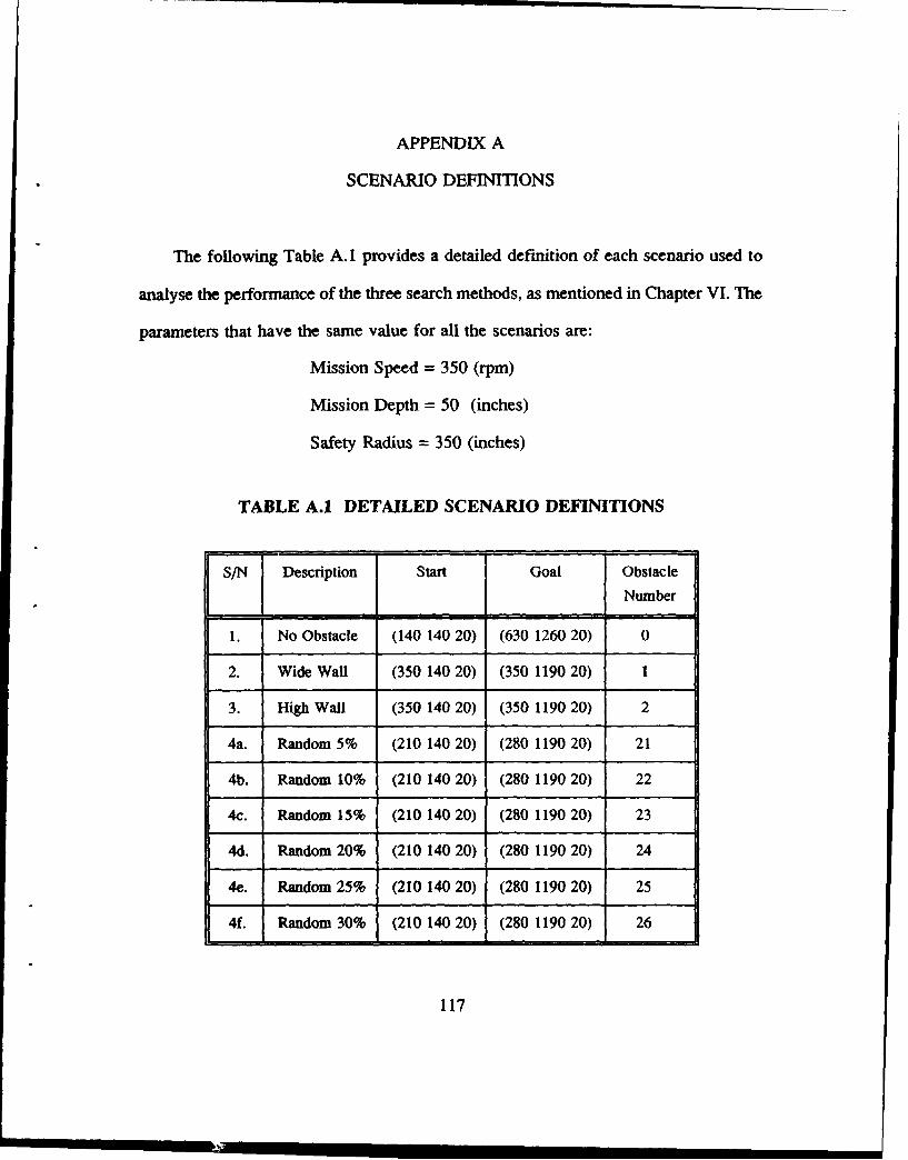
APPENDIX A
SCENARIO DEFINITIONS
The following Table A. 1 provides a detailed definition of each scenario used to
analyse the performance of the three search methods, as mentioned in Chapter VI. The
parameters that have the same value for all the scenarios are:
Mission Speed = 350 (rpm)
Mission Depth = 50 (inches)
Safety Radius = 350 (inches)
TABLE A.1 DETAILED SCENARIO DEFINITIONS
S/N Description Start Goal ObstacleNumber
1. No Obstacle (140 140 20) (630 1260 20) 0
2. Wide Wall (350 140 20) (350 1190 20) 1
3. High Wall (350 140 20) (350 1190 20) 2
4a. Random 5% (210 140 20) (280 1190 20) 21
4b. Random 10% (210 140 20) (280 1190 20) 22
4c. Random 15% (210 140 20) (280 1190 20) 23
4d. Random 20% (210 140 20) (280 1190 20) 24
4e. Random 25% (21014020) (280 1190 20) 25
4f. Random 30% (210 140 20) (280 1190 20) 26
117
APPENDIX B
AUV TESTBED SIMULATOR USER MANUAL
A. HARDWARE CONFIGURATION
The laboratory AUV testbed simulator is comprised of the following systems:
1. Symbolics 3675 LISP machine
2. Symbolics Color Monitor
3. Silicon Graphics IRIS (SGI) 4D/70GT graphics workstation
The Symbolics LISP machine is directly connected to the Symbolics Color
Monitor, and the two together make up the Mission Planning workstation. The former
hosts the mission planning software and interfaces with the user via a series of mouse-
driven panels, facilitating the interactive input of mission data and the monitoring of
the progress of the mission planning cycle; the latter displays the derived path as well
as the actual path during the execution phase, in two-dimensional plan and side
elevation views of the NPS pool (for the purpose of feedback and evaluation). The
SGI graphics workstation is used for 3-D visualization of the vehicle and the
environment during a simulated execution of the mission; it comes with a side
terminal which is used for starting the program as well as for displaying user prompt
messages during the simulation. Communication between the Mission Planning and
the SGI graphics workstations is facilitated by an ethernet local area network on which
118
they reside. In this manual, the term AUV testbed simulator refers to the complete
laboratory testbed configuration, while the AUV graphics simulator refers only to the
SGI graphics workstation.
B. PRE-REQUISITE FOR USING THIS MANUAL
This manual assumes some basic familiarity with the Symbolics LISP machine
and the IRIS graphics workstation. The user is also required to be familiar with the
elementary commands in the Unix operating system such as those for login on,
traversing the hierarchical directory structure, and simple file manipulations. Finally,
some nominal experience with the LISP machine and the KEE expert system shell is
required for proper startup and shutdown of the AUV testbed simulator; in-depth
knowledge of its operation is not needed.
C. THE SGI GRAPHICS WORKSTATION
The operation of the AUV graphics simulator is described in detail by Ray [Ref.
191; it is updated and included here both to reflect the changes made and for
completeness. The simulation is normally run on the IRIS 4D/70GT, specifically IRIS-
5, because of its physical proximity to the LISP workstation, which allows easy
viewing of both workstations during the autopilot mode of operation. However, all the
IRIS machines are networked in a manner that allows the simulation to be run on
either IRIS-I, IRIS-4, or IRIS-5.
119

1. Start-Up Procedure
To start the simulation, "log on" to the auv account on both the IRIS
workstation and the side terminal of the IRIS, and then transfer to the directory
Iworkiauvlongsm (where the auv programs reside). Start the simulator program by
entering the command auv on the side terminal followed by a carriage return. It takes
about 10 seconds to initialize and to read in the object data files of the vehicle and the
pool, before the graphics is fully displayed on the main IRIS graphics workstation.
2. Display Viewing Controls and Vehicle Controls
When the simulation is started, the right side of the graphical display shows
a control panel with a set of sliders. This panel provides two types of control: the
display viewing controls and the vehicle controls. The viewing controls are those
shown on the top half of the control panel and they are used to alter the viewer's
perspective of the display. The vehicle controls, shown on the lower half of the control
panel, are used to manually steer the vehicle. All controls shown are activated by
using the mouse to manipulate the sliding markers as follows: first, position the cursor
at the appropriate slider, then press and hold down the left mouse and drag the marker
to the desired new value while still holding down the left mouse. Note that changes
to the user's viewpoint using the viewing conrols, should be executed slowly or the
user may lose his own perspective in the display.
120
3. Manual and Autopilot Modes
The simulator can be operated in either the manual or the autopilot modes.
In the manual mode, all vehicle controls shown on the display are active, while in
autopilot mode, they are inhibited since the Mission Planning workstation provides the
control commands to the vehicle. Note that the display viewing controls are always
active. The initial default mode is the manual mode; here the simulated vehicle starts
on the surface of the pool with a speed of 25 rpm on course east.
4. Autopilot Mode
The autopilot mode is started by pressing in sequence the ESC-key and the
A-key on the main keyboard of the IRIS workstation. Pressing the ESC-key brings the
vehicle to the original default starting position, while hitting the A-key puts the system
in autopilot mode. After activating the autopilot mode, the side terminal will indicate
that the IRIS server is waiting to connect to syml (the Symbolics LISP machine) and
the following message will prompt the user to start the KEE portion of the simulator
to connect the LISP client to the IRIS server:
Ready to commence execution phase
Server waiting to connect to syml
Server waiting to connect to symi
The autopilot execution can be interrupted by pressing the Q-key which
brings the system back to manual mode; if this is done, the autopilot cannot be re-
started without exiting the program. Note that the communications sockets must be
broken when the program is exited, as explained in the next section.
121
5. Exiting the Simulation Program
The simulation can be interrupted and the program exited at any point
during the autopilot simulation mode by using the pop-up menu. The pop-up menu can
be brought up by pressing the right mouse. Selecting the exit option on the menu of
choices will terminate the display program.
However, the above procedure is still incomplete. One important additional
step that must be taken is to break the communications (send and receive) socket
connections on both the IRIS workstation and the Symbolics Lisp machine. This must
be done on the IRIS server first and then on the Lisp machine. To break the socket
connections on the IRIS, go to the side terminal and list the current processes by
entering the Unix command ps. This brings up a list of active processes together with
their corresponding process numbers. Stop any send/receive communication daemons
with the kill <process number> command. This must then be followed by a
corresponding step on the Symbolics Lisp machine, by doing SELECT-L to enter the
Lisp Listener and issuing the command (end-con) to end the "conversation".
Note that this procedure to break communications as described, must be
repeated if, on the next activation of the autopilot mode, the system reports that the
sockets are already in use. Usually, the procedure is performed not more than twice.
122
D. THE AUV TESTBED SIMULATOR
1. Initial State of SGI Graphics Workstation and the Symbolics Color
Monitor
To start the AUV testbed simulator, the three systems comprising the
testbed need to be put in the initial state as follows. First, put the AUV graphics
simulator in autopilot mode, by following the steps described in the previous section.
This is the initial state for the graphics simulator. Next, ready the Symbolics Color
Monitor (of the Mission Planning workstation) by simply depressing the "on" button;
if the display is "blurry", press the "degaussing" button and hold it for at least 2
seconds.
2. Initial State of Symbolics Lisp Machine
The next step involves initializing the MPES software on the Symbolics
LISP machine. First, "log on" to the machine by first doing a SELECT-L to bring up
the LISP Listener window (if not already displayed), and then issuing the command
login auv; this login procedure puts the user in the auv project account on the LISP
machine.
The next thing to do is to load the auv-mpes desktop into the KEE
environment; this desktop encapsulates the MPES knowledge-base and reserves the
workspace needed by the program. The load procedure is as follows. First, do a
SELECT-K to get into the KEE environment. Then use the mouse to point the cursor
123
at the desktop icon at the upper left comer of the screen and depress the left mouse
button. When a pop-up menu appears, select the Load Desktop option. A KEE
"typescript" window will appear requesting the name of the desktop to be loaded: enter
sym4.>auv>ongsm>auv-mpes.lisp. KEE will then respond by first loading the required
lisp files and then the MPES knowledge base. (The lisp files contain the lisp functions
used by the MPES knowledge base). Loading is completed when a shadow mouse
appears on the screen; clicking the left mouse button at this stage will bring up the
initial screen of the MPES. The Mission Planning workstation is now ready for
operation.
3. Mission Planning and Construction Phases
The procedure for planning a mission during the planning and construction
phases, is performed on the Mission Planning workstation as described in Section D
of Chapter IV.
4. Mission Execution Phase
The execution phase is started by selecting the execute option from the
execute-abort panel on the Mission Planning workstation (see Figure 4.6 and Section
D of Chapter 4). This selection triggers the establishment of the communications
between the IRIS graphics simulator and the Mission Planning workstation. The
Mission Planning workstation then initiates a "conversation" with the IRIS, and then
sends it the coordinates of the initial position of the vehicle and any obstacles that
124
may be defined for the environment. When the data has been transferred, it issues the
following message on the KEE "typescript" window:
Iris5 communication selected.
A conversation with the iris has been initiated.
Connection with iris established.
Initial A UV state sent to iris
Hit a key on Iris5 main terminal to continue
At the same time, the IRIS displays a corresponding message on the side terminal as
follows:
Obstacles received from lispmachine
Initial position obtained from lispmachine
Hit any key to receive waypoints from lispmachine
To proceed, hit any key on the main IRIS workstation keyboard. This
causes the display program to begin reading in the waypoints sent by the Lisp
machine. Note that the transfer of the waypoints from the Lisp machine to the IRIS
is not required, and is done only so that the complete path can be displayed on the
IRIS for debugging purposes. Upon completion of this transfer, the actual execution
then begins.
125
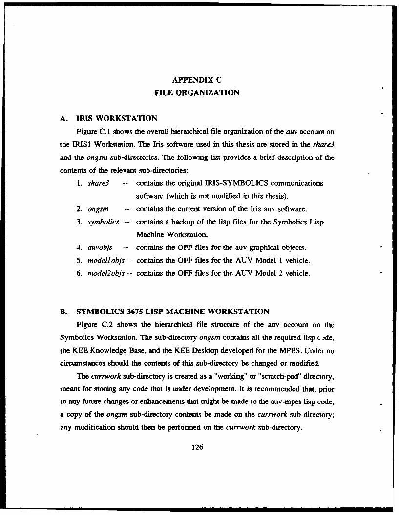
APPENDIX C
FILE ORGANIZATION
A. IRIS WORKSTATION
Figure C. 1 shows the overall hierarchical file organization of the auv account on
the IRIS 1 Workstation. The Iris software used in this thesis are stored in the share3
and the ongsm sub-directories. The following list provides a brief description of the
contents of the relevant sub-directories:
1. share3 -- contains the original IRIS-SYMBOLICS communications
software (which is not modified in this thesis).
2. ongsm -- contains the current version of the Iris auv software.
3. symbolics -- contains a backup of the lisp files for the Symbolics Lisp
Machine Workstation.
4. auvobjs -- contains the OFF files for the auv graphical objects.
5. modellobjs -- contains the OFF files for the AUV Model 1 vehicle.
6. mnodel2objs -- contains the OFF files for the AUV Model 2 vehicle.
B. SYMBOLICS 3675 LISP MACHINE WORKSTATION
Figure C.2 shows the hierarchical file structure of the auv account on the
Symbolics Workstation. The sub-directory ongsm contains all the required lisp c.jde,
the KEE Knowledge Base, and the KEE Desktop developed for the MPES. Under no
circumstances should the contents of this sub-directory be changed or modified.
The currwork sub-directory is created as a "working" or "scratch-pad" directory,
meant for storing any code that is under development. It is recommended that, prior
to any future changes or enhancements that might be made to the auv-mpes lisp code,
a copy of the ongsm sub-directory contents be made on the currwork sub-directory;
any modification should then be performed on the currwork sub-directory.
126
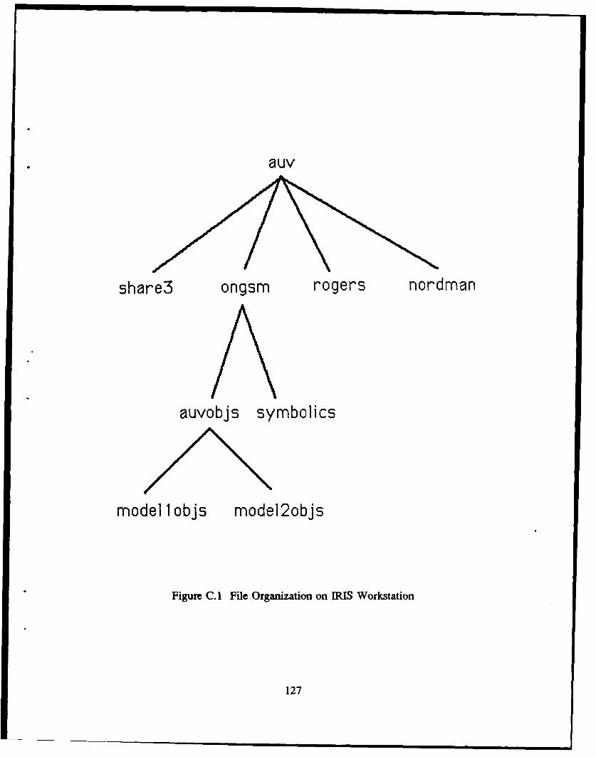
auv
share3 ongsm rogers nordman
auvobjs symbolics
model 1 objs model2objs
Figure C. 1 File Organization on IRIS Workstation
127
auv
currwork ongsm rogers
Figure C.2 File Organization on the Symbolics Workstation
128
APPENDIX D
PROGRAM LIST
This appendix contains the source listings of the lisp code developed for this
thesis. They are stored in several files as listed below:
1. array.lisp
2. astar-best.lisp
3. boot.lisp
4. eval.lisp
5. hsearch.lisp
6. monitor.lisp
7. obstacle.lisp
8. posn.lisp
9. succ.lisp
10. sym-iris-comm.lisp
11. missions.lisp
12. mission-agents.lisp
13. umissions.lisp
The last three files, "missions.lisp", "mission-agents.lisp", and "umissions.lisp"
contain the methods (lisp functions) referenced directly by the KEE units. hi addition
to the above list, two other major files exist: mpexpert.u and auv-npes.lisp. These two
files are automatically generated by KEE when the Knowledge Base and the Desktop
(respectively) are created; they are not included here due to their excessive length, and
also because it would not benefit the reader of this report.
129
-- Package: USER; Mode: LISP: Syntax: Common-Lisp; Base: 10--
;Filname..* array.l13pAuthor .............Onq Seow Henq
Date Created ... : 18 Aug 1989Description .... : This file contains lisp code that build the aa.auation function
* map (enap) . For convenience, the emap is implemented as a.- dimensional array corresponding to the pool environment in the
* grid-system. Actually a complete 3-dimensional array is not necessary* for keeping track of the obstacle locations (virtual and real) and
for path marking - a two-dimensional map with a pointer to a linkedlist of obstacle Positions is sufficient (and more storage efficient)should be considered.
Modifications..:
(DEFUN make-emap 0)(SETF **map* (MAKE-ARRPAY (list (4 *xmapsize* 2)
(4 *ymapsize' 2)(4- *zmapsize' 2) ))
(DEFU N initpoolemap ()(applyarrayfn #'aelmt_dist_to_goal *emap*
1 *XMapsiZO* 1 *ymapsize* 1 *ZM&P31ZG*(mark emapboundaries)
(DEFUN mark snap boundaries C);x-z plane boundaries
(applyarrayfn 8' aelmt mnit -to_infinity**Map- 0 (14 '*..apsiZO*) 0 0 0 (1+ *zmap3iZ**))
(applyarrayfn 8' aelmt mnit-to -infinity*emap* 0 (1+ 'xmapsize*)
(1+ *Ymapsize*) (1+ *ymapsize')0 (1+ *imapsize'))
y-z plane boundaries(apply_.array fn Vaelmt imit -to -infinity
'emap* 0 0) 0 (14 *yMapsize') 0 (14 *ZMap31Ze*))(apply array fn * aelmt_mnit to-infinity
*snap' (1+ *;mapgize') (1+ 'XMapsiZe*)0 (14 *ymapsiz6*)0 (14 *Zmapsize*))
x-y plane boundaries(apply_ array fn 8' aelmtminit -tominfinity
'emap' 0 (14 'xmapsize') 0 (14 'ymapsize*) 0 0)(apply array fn 8' aelmt imit to infinity
*Gnap' 0 (14 ',cpMpsize*)0 (14 *ymapsize*)(1+ *Zmapsizo*) (1+ 'Zmapsize*))
(DEFUN applyarrayfn(fname array x-start x-end y-start y-end 2-start z-end)(DO ((xindex x-start (1. xindex)))
((' xindex x-end))(DO ((yindex y-start (14 yindexf)
((> yindex y-end))(DO ((%index z-start (14 zindex))
((> zindex z-*nd))(funcall fname array xindex yindex zindex)
130
(CEUUN aelm_nit_to_zero (array i j k)(SETF (AREF array i j M ) a)
*(DEFUN aulift iiit -to -infinity (array i j k)
(SETF (AREF array i j M) *infinity*)
(DEFUN aelmtdist.togqoa (array i j k)
(SETF (AP.EF array i j k) (d.t-bet~ponsf (LIST i jk) *goa*))
131
Mode: LISP; Package: USER; Base: 10; Syntax: Common-lisp -
...... * ......... * ..... . ................
Filename ..... : astar-best.l13PAuth or .. .. : Ong Seow Meng
Oate Created ... : Oct 1989Description .. : This file contains the lisp functions for A* and Best-first searches.
Modifications..:
* n s n.f........ ......l f
Functions specific to Best First Search----------- ---- - ----- ---- ---- ----- -------------------- -----
(DEFUN bestfirst.search 0)(SEIT *given-mi ssi on -depth* 'mnission-depth')(SETF *path* (betfirstsearch2 (LIST (LIST *start*)) *goal*))
(DEFUN betfirst searchZ (queue goal-posn)(IF (> (LENGTH queue) 'n.ax-qlength') (SETF *max-qlength* (LENGTH queue)))(LET' ( (curr-posn (posn (FIRST (FIRST queue))))
(horiz-dist-to-goal (horizcoord-dist curr-posn goal.-posn))(IF (<- horiz-dist-to-goal -safety-dist')
(SETF *'mission-depth' (z 7coord goal-posn))(SETF 'mission-depth' 'given-mission-depth')
(COND ((NULL queue) NIL)((within vicinityp (posn (CAAR queue)) 'goal-vicinity-list*)
(reverse (FIRST queue)))(T (bestfirst-search2 (SORT (APPEND (bestfs expand -node (F RST qrueue)) (REST cqueue))
*'(LAMBDA (pathi path2) (smaller_0stirmationp path! path2 goal-posn))V'(LAMBDA (pathi path2) (closerp pathi path2 goal-posn))
goal-posn)
(DEFUN bestfs expand node (path)(eliminate_circularpaths
(MAPCAR 8'(LAMBDA (child) (CONS child path))(remove obstacle succs (successorS (FIRST path))I
(DEFUN smaller estimationp (pathl path2 qoai-posnj(LET' (pathi-st-ate (FIRST pathl))
(path2-state (FIRST path2))((bestf festimation (direction pathl-state) (posn pathl-state) qoal-posn)
(bestf estimation (direction path2-statel (posn path2-state) goal-posn)
(DEFUN bestf-estimation (succ-dir succ-posn goal-posn)(LET ( (coord-dist-to-qoal (+ (horiz coord d13t succ-posn goal-poan)
(abs-vert -coord - ist succ-posn goal-posn))(+ (dixtbetpsnz succ-posn qoal-posm)
(COND ((<- coord-dist-to-goal 'safety-dist') 0)(T (rotational coat succ-dir succ-posn goal-posn) )
132
Functions specific to A-star Search
The structure of 'path' in Astar Search is:(Mode evel-fn coat-so-far (dir (xn yn zn)) (dir (xn-l yn-l zn-i))........
..........(dir (xstart ystart zutart))
(DEFUN astar.search ()(SETT *given-minsion.depth* *mission..depth*)(SET? *path* (astar-search2 (LIST (LIST 'Normal-Mode 0 0 *start*)) *9oal*)
(DEFUN astar-search2 (queue qoal-poon)(IF (> (LENGTH queue) *max-qlength*) (SETF *max-qlength* (LENGTH queue)))(LET* ( (curr-posn (poan (FOURTH (FIRST queue))))
(horiz-dist-to-goal (horiz-coord-dist curr-ponn goel-posn))(IF (<- horiz-dist-to-goal *safety-dist*)
(SETF *mission-depth* (z__coord goal-poan))(SETF *mission-depth* *qiven-mission-depth*)
(COND ((NULL queue) NIL)((within vicinityp (poan (FOURTH (FIRST queue))) *goal-vicinity-list*)
(reverse (CDODR (FIRST queue)))(T (astar-search2 (SORT (remove higher costpaths
(&star -expand node (FIRST queue) goal-posn)(REST queue)
#' (LAMBSDA (pathl path2)(smaller e valuationp pathi path2)
goal-posn))))
(DEFUN remove higher costpaths (new-list-of-paths curr-queue);removes the higher cost path if two paths lead to the same state.
(COND ( (NULL new-list-of-paths) curr-queue)((NULL curr-queue) new-list-of-paths)(T (LET* ( (curr-new-path (FIRST new-list-of-paths))
(burr-old-path (FIRST curr-queue))(curr-state-new-path (FOURTH curr-new-path))(curr-state-old-path (FOURTH curr-old-path))
(IF (EQUAL curr-state-new-path curr-3tate-old-path)(LET ( (new-path-cost (THIRD curr-new-path))
(old-path-cost (THIRD curr-old-path))(COND ( (< new-path-cost old-path-cost)
(CONS curr-new-path(remove higher costpaths (REST new-list-of-paths)
(REST curr-queue) ) ) :;)(T (remove-higher costpaths (REST neW-list-of-paths)
curr-queue)(CONS curr-new-path (remove higher cost paths
(REST new-list-of-paths) curr-queue ) )))
(DEFUN astar expand node (path qoal-posn)(LET ( (cost-so-far (THIRD path))
(curr-state (FOURTH path))(SET? *Current-Mode* (FIRST path))(LET ( (suc-list (remove-obstacle_succs (successorS curr-state)))
(REMOVE-IF#, (LAMBDA (a-path)
(LET ( (path-posn-list (getpathjposn list (CDOR apath)))(MEMBER (FIRST path-posn-list) (REST path-posn-list))
(MAPCAR #' (LAMBDA (child)(APPEND (LIST *Current..Mode*
(astar-evaluation curr-state child cost-so-far):11 (aster-evaluation curr-state child goal-poan cost-so-far)
(+ cost-so-far (aster_delta-cost curr-state(posn child))
(CONS child (CDOR path))
suce-list ) ) ) )
133
(DEFUN astar-evaluation (curr-state suce-stace cost-so-far)(+ cost-so-far (evaluation curr-state succ-state))
(DEFU4 astar delta cost (curr-state SUCC-posn)(local-cost (direction curr-st ate) (poan curr-stat.) succ-posn)
(DEFUN smaller evaluationp (pathi path2)((SECOND pathi) (SECOND path2))
Functions shared by both Best-First Search and A-star Search
(DEFUN cost-ofpath (path-state-list)(DO* ( (curr-state-list path-state-list (REST curr-state-list))
(curr-state (FIRST curr-statS-l13t) (FIRST curr-state-list))(next-state (SECOND curr-state-list) (SECOND curr-state-list()(curr-dir (direction curr-state) (direction curr-state))(curr-Posn (posn curr-state) (posn curr-state))(next-poan (poan next-state) (poan next-state))(total-cost 0))
C(NULL (CDDR. curr-state-list))(total-cost (loCalCost (direction (FIRST curr-state-list))
(posn (FIRST curr-3tat.-list))(poan (SECOND curr-state-list)) )
(SETF total-cost (+ total-cost (local-cost curr-dir curr-posn neXt-posn)))
(DEFUN within -vicinityp (position vicinity-21st)(COND ((NULL vicinity-list) NIL)
(EQUAL position (FIRST vicinity-list)) T)T (within-vicinityp position (REST vicinity-list)))
(DEFUN successorS (curr-state);returns the list of successors of the current state according to curr-mode.
(COND ((EQUAL *Current-Mod** 'Obstacle-Mode)(IF *DEBUG* (PROGN (PRINC 'Obstacle-Mode) (TERPRI)))(obst mode successorS curr-state)
(EQUAL *Current..Nod* 'Near-Obst-Edge)(IF *DEBUG* (PROGN (PRINC 'Obstacle-Edge) (TERPRIW)
(obste- dqe_successorS curr-state)(EQUAL *Current-Mode* Norma.1-Mode)
(IF *DEBUG* (PROGN (PRINC 'Normal-Mode) (TEPRPRIM)(normal mode-successorS curr-stat6)
(DEFUN normal-mode-successorS (curr-state)(dot search mode curr-state)(LET ( (succ-list (get succ-list curr-state *search-mode*))
(CONO ((all-are obstaclesp succ-list)(SET? -Curront-Mod* ' Obstacle-Mode)(successorS curr-state)
T suct-list)
134
(OEFUN obst mode successorS (curr-state):returns the list of successors of current state and;determsiones if ready to proceed to ONear-Obst-Edge-.(LET* ( (search-sequence
(IF 'Bottom-Search-Preferred' *AS-BF-bot-preferred-sequencu*'AS-BF-top-preferred-sequence')
(first-mode-to-try (FIRST search-sequence))
(LET ( (SUCC-l13t(REMOVE-IF #' (LAMBDA (&-successor) (is valip (posn &-successor)))
(get succ list curr-statt first-mode-to-try)(IF (NOT (all are obstaclesp succ-list))
(?ROGN (IF *DEBUG' (PROGN (PRINC 'at-least-ono-openinq!) (TEAPRI)))(IT (OR (no obstaCles insUecCliatp SUCC-list)
(depth -threshold reached (zcoord (poan curr-statef)*get out of 'Obstacle-Mode' if none of the successors.are obstacles.
(SET? 'Current-Mode' 'Near-Obst-Edge)(remove obstacle succ3 3ucc-1isc))
else try the rest of sequence but remain in Obstacle-Mode.(DO* (curr-seq-ls (REST search-sequence) (REST curr-3*q-ls))
(curr-smode (FIRST curr-seq-1s) (FIRST curr-seq-1s))(succ-liSt (gts3ucc).ist curr-state curr-smode)
(qet_3UCCl13t curr-state curr-smode)(NOT (all are obstacleap SUCC-liut))
(PROGN (IF -DEBUG* (PROGN (PRINC 'returnedsucc_list_(PRINC succ-list) (TE4PRI) )
(remoVe obstacle -succ3 sUCC-list)))))
(DEFUN obst edqe successorS (curr-stato)(LET;* ( (fwd-level-succ-list (fwd-level-succ -list curr-stats,))
(toward-mission-depth-succ-list (IF (< (depth curr-state) -1ission-de9,th*)(fwd -dive_succ list curr-state)(fwd rise succ list curr-3tate) )
(total-3ucc-list(REMOVE-IF #' (LAMBDA (&-successor) (is wallp (posn a-successor)))
(APPEND fwd-level-succ-list toward-mission-depch-succ-lisc))(COND ((no-obstacles in succ listp total-succ-list)
(SETF 'Current-Mode' 'Normal-Mode)(successorS curr-state))
(all are obstaclesP total-succ-list) (SET? 'Current-Mode' 'Obstacle-Mode)(successorS curr-state)
T (IF (NOT (all are obstaclesp fwd-lovel-succ-list))fwd-lovel-succ-listtoward-mission-depth-succ-list )
(DEFUN all-are -obstaclesp (succ-list)(CONO (NULL succ-list) T)
(NOT (is obstaclep (posn (FIRST succ-list)))) NIL)T (all-are-obstaclesp (REST suce-list)))
(DEFUN getpathposnjlist (path-state-list)(CONO (NULL path-state-list) NIL)
T (CONS (posm (FIRST path-state-list))(qetpathposn list (REST path-state-list)) )
(DEFUN remove obstacle succa (succ-list)(REMOVE-IF U' (LAMBDA (card-succ-state)
(is -obataclep (posh cand-uucc-state))succ-list ))
(DEFUN eliminate circularpaths (list-of-paths)(REMOVE-IF
#' (LAMBDA (akpath)(LET ( (path-pos-list (qetpathposnjlist &_path))
listof-~th) )(MEBER (FIRST path-posm-list) (REST path-posn-list))
135
-- Package: USER; Mod*: LISP; Base: 10; Syntax: Common-Lisp
**Wt~W*......,..*.***W*,*** W*,****.*.* .................. t
: Filna me.....: boot.liap;Auth or....: Ong Seow Menq
; Date Created ... : 27 Doe 1989;Description..: This file contains the global variable and global constant
definitions as well as the parametr-initialization routines.
Modifications..:
GLOBAL VARIABLES
(DEFVAR *DEBUG* N4IL)
(OEFVAR 'goal')CDEFVAR 'start*)(DEIVAR 'mission-depth')tO~FVAR 'given-target-depth')(DEFVAR 'safety-dist')(DEFVAR 'path')CDEFVAR 'real-path')(DEFVAR -return-path')(OEFVAR 'goal-vicinity-list')C0EEV 'curr-speed')(DEEVAR 'vert-mvt-speed')(DEE'VAR 'vert-turninq-speed')(DEFVAR 'ii3-sYM-Conuns-*stablished') ::set by send carameters toIRIS
reset by abort mission method of EXECUTOR
(DEFVAR '*map')(DEFVAR 'xmapsize')(DEFVAR *yMap31Z*')(DEFVAR 'zmapsize*)
(DETJ1AR 'ObstacleLs')(DEFVAR 'HumObstacles')
(DEFVAR 'risk-factor')(DEFVAR 'real-horiz-dist-pu-coord' 70.0)(OEFVAR 'real-vert-dist-pu-coord* 10.0)%DEFVAR 'up-costpu-dist')DETVAR 'dovn-costpu-dist')DETVAR 'approx-half-real-horia-dist-pu-coord')
(DEFVAR '3ottoum-S*arch-Preferred*)(DEFVAR 'top-preferred-sequence')(OEFVAR 'bottom-preferred-sequence')
(DEFYAR *search-mode')(DEFVAR 'Obstacle-Mode')(DETVAR *Mear-Obat-Edqe')
136
GLOBAL CONSTANTS
;; Constants used in path search programs(DEFCONSTANT *PI* 3.142)
(DEFCONSTANT *half-I* (U *PI* 2))(DEFCONSTANT *one-eiqht-PI* (/ *PI* 8))
(DEFCONSTANT *infinity* 100000)(DEFCONSTANT -deq-to-rad-factor* (I *PI* 180.0))(DEFCONSTANT *rad-to-deq-factor (1 180.0 *PI-))
LOADFILES loads all the files containing the required lisp functions
(DEFUN loadfiles 0(load "sym4:>auv>currwork>array")(load "sym4:>auv>currwork>obstacle")(load "sym4:>auv>currwork>posn")(load "sym4:>auv>currwork>succ")(load "sym4:>auv>currwork>eval*)(load -sym4:>auv>currwork>hsearch")(load -sym4:>auv>currwork>astar-best")(load "sy' 4 :>auv>currwork>monitor")(load "sym4:>auv>currwork>sym-iris-comm")(load "sym4:>auv>currwork>umissions')(load "sym4:>auv>currwork>mssions")(load "sym4:>auv>currwork>mLssion-agents")
INITSEARCH PARAErERS function initializes the system parameters used for path search.
(DEFUN init_s*archnparameters ()(IF *DEBUG* (FORMAT T "-% Entered function 'init system parameters'."))(SETF *risk-factor* 90)
(SETF *risk-factor- 0)(SETF *vert-mvt-speed* 200.0)(SETF *ver-turninq-speed* 200.0)(SETF *real-horiz-dist-pu-coord* 70.0)(SETF *:eal-vert-dist-pu-coord* 10.0)
(SETF *approx-half-real-horiz-dist-pu-coord-(- (/ *real-horiz-dist-pu-coord* 2) 0.1))
(SETF *up-costpu-dist* 1.2)(SETF *down-costpu-dist* 1.2)(SETF *top-preferred-sequonce* '(fwd-rise fwd-level top-rl fwd-top top
fwd-dive bot-rl fwd-bot right-left back-up)(SETF *bottom-preferred-sequence* '(fwd-dive fwd-level bat-rl fwd-bot bottom
fwd-rise top-rl fwd-top riqht-left back-up)(SETF *AS-BF-top-preforred-sequonce- '(fwd-rise-and-level top-all-and-rl
fwd-dive bet-all back-up) )(SETF *AS-BF-bot-preferred-sequencea (fwd-dive-and-level bot-all-and-r
fwd-rise top-all back-up)
(init searchparameters)(loadtiles)
137
Lm r
Package: USEP.: Mode: LISP: Syntax: Common-Lisp: Base: 10
Filenam .. * eval.lispAuthor ... : Ong Soow Hong
Date Created ... : Is Aug 3.989Description .... : This file contains the lisp code for computing the evaluation
function and it component costs, used in )Huriatic search.
Modifications..:
(DEFUN evaluation (curr-state suce-state)returns the evaluation function (F) in MAIN mode.
F -C +Ewhere C - local-cost function
E - estimation function(4 (local-cost (direction curr-state) (posn curr-stats)
(posm succ-state))(estimation (direction suce-state) (posn succ-state)
(DEFUN estimation (succ-dir succ-posn)returns the estimation functionE - T(CPn~l,Pgoal) + PM(CPn~l) + R(C~n'tl,Pgoal)
where (T + PM) is stored in estimation map, emap+ translation cost succ-posn *goal*
(4 (AP.EF 'emap* (x-coord 3ucc-posn)(y-coord succ-posn)(z -coord 3ucc-posn)
(rotational-cost succ-dir succ-posn *goal-)
(DEFUN local cost (curr-dir curr-posn tqt-posn)Ireturns the local cost C - T + R
where T - translational costR - rotatioual cost
(+ (translation-cost curr-posn tqt-posn)(rotational_cost curr-dir curr-poan tqt-posn)(risk cost tgt-posn) )
(DEFUN risk cost (candidate-posn)* ' risk-factor' (depth to go candidate-posn))(LET ( (dist-from-start (horizontal-dist candidate-posn (posn *start*)))
(dist-rom-goal (horizontal dist candidate.-posn *goal'))(COND ((<- dist-from-goal 'satety-dist-)
(SETF 'mission-depth* (zcoord *goal*))
(DEFUN depthtogqo (posn):; (LET ((curr-depth (- 'zmapsize* (z-coord posn))))(ASS (- 'mission-depth' (xzcoord posn)?
(DEFU translation cost (curr-poen tqt-posn);; returns the translational cost (T) from curr-po-in to tqt-posn.(+ (depth change cost ourr-posn tqt-posn)
(horizontal dist cc-posn tgt-posn)
(DEFUN depth chanqe cost (posn3. posn2)returns the cost of changing depth in movingfrom posn2. to posn2.
ILET ((vert-dist (vertical dist posnl poxn2Ml(CONO C vert-dist 0) o)
(.vert-dist 01 C' up-costpu-dist* (ABS vert-dis;;))) :; moving tip towards surface((vert-dist 0) C' down-costpu-dist' (ABS vert-dist) ))
138
COETUN rotational cost (curr-dir curr-poun tgt-Pesn)returns th;e turninq cost (RC) in moving from curr-posn to tgt-posn*'real-horiz-disc-pu-coerd*(COND ((- (hon:_-coord-disc curr-posn tqt-ponn) 0) 0)
(t (LET* ((new-dir (azimuth curr-posn tgt-posn))(abs-delta (ABS (turn angle curr-dir new-dir)))(turn-quantum U/ abs-delta 0.3926991))turn-quantum is in units of 22.Sdeq.
(PR37(C 'turn-quantum-- ) (PRINC turn-cquantum) (TERPRI)(COND ((renqep turn-quantum 0 1) 0)
((ranqep turn-quantum 1 3) 0.1)f(ranqep turn-quantum 3 5) 0.5)(Cranqep turn-quantum 5 7) 1.0)((ranqep turn-quantum 7 9) 2.0)((ranqep turn-quantum 9 11) 1.0)((ranqep turn-quantum 11 13) 0.5)(Cranqep turn-quantum 13 15) 0.1)((> turn-quantum 15 )0) ))
(DEFUN rangep (var lower upper)(IT (AND (>- var lower) (c var upper)) t NIL)
(DEFUN azimuth (from-poan to-poan);azimuth is the angle in x-y plane with zero along the y-axis
(ATAN (xcoord-diff from-pan to-posn)(ycoord-diff frOM-posn tO-poan)
(DEFJI turn angle (azimuthl azimuth2)Cazimuth2 azimuthl)
(DEFUN dir quantum (azimuth)UI azimuth -one-eiqht-PI')
COEFUN dist bet_ons (posnl posn2)(SORT C(- (sqr (horizontal dist posni posn2))
Csqr (vertical dist posnl posn2)) )
(DEFUN horizcoord -dist (posnl pasn2)(SORT C+ Csqr Cabs xcoord diff posnl posn2))
(sqr (absycoorddiff posnl posn2)))
(DEFUN abs vert_coorddist (posnl posn2)(abs-zcoord-diff posnl posn2)
(DEFUN horizontal -dist (posnl posn2)(I *real-horiz-dist-pu-coord* (hariz-coord-dist posnl posn2))
(DEFUN vertical -dist (posnl posn2)(* 'real-vert-dist-pu-coord* (zcoord-diff posnl posn2)
(DEFUN sqr (n)(* n n)
(DEFUN abs -xcoord diff (pomnl posn2)(ABS C- (;xcoord pean2) (xcoord posnl)))
(DEFUN absycoord -diff (posnl posn2)CASS (- ycoord posn2) (ycoord posnl)))
(DEFU abs zcord diff (posm2. posn2)CAB C- (iscoord posn2) (zcoord posnl)))
139
(DEFUN4 xcoord diff (Pozn1 POSn2)(- fxc oord poafl2) Cx-coord posnhi))
(DETUN ycoord diff (posn. pogn2)C- Cyc oord poari2) (ycoord pomtnl)))
(OETUN zcoord diff (pani pomn2)C- CZ-Coord posn2) (z-coord posnhi))
(!mFtm x coord (pasn)(CAR posn))
(OEFUN y-Coord (pomn)CCADR poan))
(DEFU)1 zcoord Cpo~n)(CADDR poan)
140
P' ackage: USER; Syntax: Commion-Lisp; Base: 10; Mod*: LISP -
A~~....... ... **SW*t***....*********S*****~S*t***......... ..... ...
Filenam e .... :hsearch.lispAuth or......: Ong Seow Mong
Date created ... : 20 Aug 1989Descrpton .. * This file contains the lisp code for heuristic search.
Note.. ....A State is defined by the list-form
(course (x y z))where (x y z) is a path planning coord.and course is north in the positive Y-axis.
Modifications.-:
...... *..*.* ... * .............. *..................
(DZFUN heuristic.3earch 0)(SETF *path* (heuristic search2 *start-))
(DEFUN heuristic_3earch2 (curr-state)(LET* ( (curr-posn (posn curr-state))
(hariz-dist-to-qoal (horizcoord dist curr-posn *goal*))(IF (<- horiz-dist-to-qoal *safety-it-)
(SETF -nission-depth* (z -coord 'goal*))(COND ( (within -vicinityp curr-posn *goal-vicinity-list*) (LIST curr-state)
(T (LET ((succ-state (successor curr-state))(path-mark curr-state succ-state)(APPEND (LIST curr-scace) (heuristic-search2 succ-3tace)) )
(DEFUN successor (curr-state);returns the best successor of the current state.
(CONO C Obstacle-Mods- (IF *DEBUG* (PROGN (PRINC ,'Obstacle-Mode) (-_ERPRr)))(get obsi mode successor curr-state))
*Near-Obst-Edq** (IF *DEBUG* (PROGN (PRINC 'ObstaclelEdge) (TERPRIMl(get obst edge successor curr-stato)
T (det_search-mode curr-state)(get normal -maoesuccessor curr-state
(get-succ-list curr-stat. *soarch-modet))
(DEFUN get obst e dge_successor (curr-state)(LET- ( (fwd-lev*1-succ-li2t (fwd level-succ-list curr-state))
(toward-mission-depth-succ-list (IF (< (depth curr-state) *mission-depth*)(fwddives3ucc-li st curr-state)(fwd-rise-succ-list cUrr-st&t)
(total-succ-list(REMOVE-IF #1 (LAMBDA (a-successor) (is walip (posn a-successor))
(APPEND fwd-level-succ-list toward--mission-depth-succ-list))(COND ((no obstacles in succ listp total-sujcc-list)
(SETF Noar-Obst-Edq** NIL)(successor curr-state))
(all are obstaclesp total-succ-list) (SETF *Near-Obst-Edge* NIL)(SETF *Obstacle-Mod** T)(successor curr-state))
(T (LET ( (best-succ (qetbestsucc curr-state fwd-level-succ-list))(IF (not obstaclep (posn best-succ))
best-succ(get best succ curr-state toward-m3slon-depth-succ-list) )
141
(DEFtJN is walip (position)(COND (OR (-(x-coord position) *XMAp3z6') -(xcoord position) 0)) T
(OR ( ycoord position) *yftApsize*) C ycoord Position) 0)) T(OR C-(zcoord position) *ZMapsiZe*) ((z-coord Position) 0)) TT NIL)
COEFUN get_obst -mode~successor (curr-state)
(LET* ( (search-sequence(IF *Bottom-Search-?referred* "bottom-preforred-sequence*
'top-preferrd-squencel)(first-mode-to-try (FIRST search-sequence)))
(IF (is walip (posn (FIRST (get succ list curr-state first -mode-ta-try)))(SEFF first-mode-to-try (SECOND search-sequence))
* (LET' ( (SUCC-li3t (getZucc li3t curr-state first-mode-to-try))(best-sUCC (get best_succ curr-state SUCe-list))
(IF (NOT (isobstaclep (posn best-succ)))(PROGN (IF *DEBUG- (PROGN (PRINC 'found-a-way!) (TERPRI))
(IF *DEBUG* (PROGN (PRINC 'firsttrYbest-succis(PRINC best-succ) (TEP.PRI)))
(IF (OR (NOT (at-least one_obstaclep sUCC-l13t))
(depththresholfdreached (zcoord (posn best-succ)))get out of *Obstacle-Mode' if none of the Successorsare obstacles.
(PROGN(IF *DFEBUG* (PROGN (PRINC 'Chanqing-to-Normal-Mode-now!)
(TEP.PRI)(SETF *Near-Obst-Edqe* T)(SETQ 'Obstacle-Mode- NIL.)
best-succ)
else try the rest of sequence but remain in 'Obstacle-Mode'.(00' ( (curr-seq-ls (REST search-sequence) (REST curr-seq-1s))
(curr-smode (FIRST curr-seq-ls) (FIRST curr-seq-ls))
(sucC-list (getsUCC_1ist curr-state curr-smode)(getsUCC Iist curr-state curr-smode)
(best-succ (get bestsucc curr-state 3ucc-list)(get best succ curr-state sUCC-list)
(NOT (is-obstaciep (poan best-succ)))(PROGN (IT *DEBUG' (PROGN (PRINC 'best-sUCC_i.s_
(PRINC best-succ) (TERPRI) )
best-sUCC))))
(DEFUN depththresho dreached (curr-depth)(CONO D > curr-depth 'zmapsize-) T)
(-curr-depth 1) V)T NIL) )
(DEFUN no obstacles_in_succ_listp (state-list)(NOT (at least one obstaclep state-list))
(DEFUN at least one obstaclep (state-list)return T if there is at least one posn in the state-list that is an obstacle:else, NIL is returned.
(COND ( (NULL state-list) NIL((is obstaclep (pasn (FIRST state-list))) TT (at least one obstaclep (REST state-List))
142
(DEFUN get succ list (curr-state 3earch-mod*);returns the list Of successor states of the cu~rrent state.
(COND ((EQUAL search-mode 'fwd-level) (fwd -level_3ucc list curr-state))((QUAL search-mode *fwd-dive) (fwd-dive-suceclist curr-state))((EQUAL search-mode, * fd-rize) (fwd rise succ list curr-state))
((QUAL search-mode 'top-fwd-rl) (top fwd rl succ list curr-state))((QUAL search-mode 'bot-fwdd-rl) (bot-fwd-rl-succ list c'srr-state))((QUAL search-mode 'top-rl) (top :1 succ list curr-state))((QUAL search-mode 'bot-rl) (bot-:1 succ list curr-state))((EQUAL search-mode lfwd-top) (fwd-top_3ucc list curr-state))((EQUAL search-mode 'fwd-bot) (fwd bat-succ list curr-state))((EQUAL search-mode 'right-left) (right left succ list curr-stat )((QUAL search-mode 'back-up) (back up succ list curr-state))
( (EQUAL search-mode * fwd-rise-and-level) (fi~d rise and level sUCC list curr-stat*))((EQUAL search-mode 'fwd-dive-and-lovel) (fwed -dive -and level-succ-list curr-state))((EQUAL search-mode 'bot-all-and-rl) (bat all and rl succ list curr-state))((EQUAL search-mode 'top-all-and-rl) (top all and rlsucc list- curr-state()((EQUAL sear-ch-mode 'top-all) (too all succ list curr-state))((EQUAL search-mode 'bot-all) (bat all_3UCC lint curr-state))((EQUAL search-mode 'top) (LIST (topposn state curr-state)))((EQUAL search-mode 'bottom) (LIST (botjposnstate curr-state))
(DEFUN get_normal_mode_successor (curr-state succ-ligt):returns the best successor state of the current state
(LET ( (best-succ (get-best_succ curr-State 3ucc-lis3t)))(COND ((is obstAclep (posn best-succ))
(SETF *Obstacle-Mode- T) (successor curr-3tate)(T best-succ)
(DEFUN path-mark (curr-state succ-state)(set eMap (posn curr-state) (+ (getemap (posn curr-state))
(local_cost (direction curr-state)(poan curr-state)(poan succ-stato) )1
(DEFUN det_search-mode (succ-state)(LET* ( (succ-posn (posm succ-state))
(succ-depth (zcoord succ-on))(COND ((OR (i3_Obstaclep succ-posn) *Obstacle-Mods-)
(SETF OCbstacle-Node* nil);(SETF *searct*-mode-' 3D-all)
(>succ-depth 'mission-depth') (SETF *search-mode* 'fwd-ri34))(-succ-depth 'mission-depth') (SETF *search-mode* 'fiwd-level))(Csucc-depth 'mission-depth') (SETF *search-mode*' fwd-dive))
(DEFUN get best succ (curr-state succ-list);returns the best successor (state) among those in succ-list
(LET* ((bost-succ (FIRST suec-list))(best-evalue (evaluation curr-state best-succ))
(DO* ((rest-list (CDR suce-list) (CDR rest-list)));termination condition and result-form
((NULL rest-list) best-succ);body of do loop
(LET* ((candidate-succ (FrRST rest-list))(candidate-evalue (evaluation curr-state candidate-succ))(COND ((< candidate-evalue best-evalue)
(SETF best-succ candidate-succ)(SETF best-evalue candidate-*value))))
143
(DEFUN posn (state)oftesa;;returns the positional coordinates o h tt
(SECOND state))
(DEFUN direction (state);returns the azimuth of the state
(FIRST state))
(DEFUN depth (state)(scoord (posn state))
(DEFUN is obstaclep (position)
(IF (EQUAL (sense position) *infinity*)
NIL)
(DE2VN not obstaclep (position)(NOT (is_obstaclep position))
(DEFUN sonse (posn)(ARE? *emap* (xcoord posn) Cycoord posn) (zcoord posn))
(DEFUN makce vicinity list (ref-posn)(LIST ref-posn
(nposn ref-posn)(sposn ref-pesn)(eposn ref-posn)(Wpo3n ref-posn)(neposn ref-posn)(nwposn ref-poan)(seposn ref-posn)(swpoan ret-posn)I
(DEFtJN send-state -to iris (state)(send-float (direction state))(sendposn to iris (Posn state))
(DEFUN sendposn to Tiris (position)(send-float (xcoord position))(send gloat (ycoord position))(send-float (z-coord position))
(DEFUN set emap (coords value)(SETF (ARE? *emap* (xcoord coords)
(y.oord coords)(z-coord coords) )value)
(DEMU get emap (coords)(ARE? *emap* (x-coord coorcis)
(ycoord coords)(azcoord. coords)
144
-- Package: USE- lode: LISP: Syntax: Common-Lisp: Base: 10
* Filenmam....: monitor.lisp* Autho r . :.. Ray Rogers: Modified by .. 0mg Seow Menq
* Date Created ...: 1989: Description....:..Contains all lisp code for generating the display on the
Side Color Monitor.
Modifications..:
*;;DEFINE VARIABLES
(DEFVAR *display-window*)CDEFVAR *display-window-array*)(DEFVAR *display-window-width*)(DEFVAR *dispiay-window-heiqht*)(DEFVAR *display-window-position*)(DEFVAR *display-window-screen*)(DEFVAR *display-window-pos*)
(DEF'JAR *main-screen*)(DEFVAR * screen-alu*)(DEFVAR *3tart..alu*)(DEFVAR *goal-alu*)(DEFVAR *icon-alu*)(DEEVAR *qrid-alu*)(DEFVAR *lettr.alu*)(DEIVAR *leqend-box.alu*)
(DEEVAR *x-screen-erg*)(DEFVAR *y-screen-org*)(DEFVAR -t-screon-orq*)(DEFVAR *scale*)(OEFVAR *vert-scale*)(DEFVAR x3)(DEFVAR ys)(DEYVAR xg)(DETVAR yg)(DEFVAR xi)(DEFVAR yi)(DEFVAA wfixnum-dist-pu-coord* (TRUNCATE *real-horiz-dist-pu-coord*))(DEFVAR *fixnum-vesrt-dist-pu-coord* (TRUNCATE *real-vert-dist-pu-coord*))
;DEFINE WINDOW AND COLORS
(DEFFLAVOR my-color-flavor ()(tv: windowtv:graphics-mixin))
(DEFUN make-color-window(window-name position inside-width inside-height&rest options &key (superior (color: find-color-screen :create-p t)
* Lallow-othor-koysj(apply * tv:make-window 'my-color-flavor
tblinker-p nil:borders 2save-bits teoxpose-p t:label nil:name window-name:position position* inside-width inside-widthsinside-height inside-height:superior superioroptions)) 145
(DEFUN make-display-window ((SET? *display-window'
(make-color-window *Display-Window"(140 10) 1220 1000))
(50 50) 1150 050))(SET? *sereen-alu' (SEND colormcolor-screen
:compute-color-alutv:alu-seta 0.3807 0.5125 1.0))
(SEND *display-vindow* :set-orase-aluf 'sar*en-alu')(SEND 'display-window' :refresh))
(DEU mnit-display ((clear-scene)
actual pooluize is 1404 by 700 (or 20 X 10 auv-lenqths);i.e. approx a ratio of 2:1;Thus, we choos, a screen-size of x-screen-sizo:y-screen-size - 2:1:The variable *scale' should be not at 1000/1400 - 500/700 - 0.7143):Also, the vertical distance per unit coord is 10.0 and height of poolis about 10 AUV heiqhts.
;Thus variable 'vert-scale' should be set at 300/(l0'l0) -3.0
(SET? *x-screen-orq* 100.)(SETF *y-screen-org' 55.)(SET? 'z-screen-orq* 650.)(SET? 'scale' 0.7143)(SET? 'vert-scale' 3.0)(draw-box)(draw depth box)monitor-display-is-ready)
(DEFUN create-display-window ((SET? 'main-screen' (SEND 'terminal-io' :superior))(make-display-window)(SET? 'd1sPlay-window-pos'
(SEND 'display-window' :position))(SET? 'display-window-screen'
(SEND 'display-window' :screen))(mit-colors)'done-init-display-window)
(DEFU clear-scene 0)(tv: sheet-force-access ('display-window')
(SEND 'display-window' :refresh)))
(DEEMN kill ((SEND 'display-window' :kill)display-window-killed)
(DFUN mnit-colors ((SET? 'start-alu' (SEND 'display-window-screen'
:compute-color-alu color:alu-x 0.406 0.9535 0.2207))(SET? 'qoal-elu' (SEND 'display-window-screen'
:coupute-color-alu color:alu-x 1.0 0.009008 0.8421))(SET? 'path-alu' (SEND 'display-v#indow-screon*
:compute-color-alu color:alu-x 0.0 0.7 1.0))-(SETr 'obst-alu' (SEND 'display-window-screen'
zcoimpute-color-alu color:alu-x 0.5 0.5 0.5))(SETr 'icon-alu' (SEND 'display-window-screen*
:couput*-color-alu colortalu-x 1.0 0.0 0.2862))(SET? 'qrid-alu' (SEND 'display-window-screen'
:compute-color-alu color:alu-x 0.9054 1.0 0.4847))(SET? 'letter-alu' (SEND 'display-window-screen'
:compute-color-alu color:alu-x 0 0 0))(SET? 'leqend-box-alu' (SEND 'display-window-screen'
icomtpute-color-alu color:alu-x 0.745 0.7243 0.7976))
146
(DEFUN draw-box C(LET* ((x-screen-size 1.000) (y-screen-size 550)
(x-interval 50.) (y-interva. 50.)(x-auv-lenqths 20.) (y-auv-lenqths 11.)(x-end-coord (4 *x-ser**n-orq* x-2creen-size))(y-end-coord (+ -y-screen-orq- y-screen-size))
(SEND *display-window* draw-rectanqlex-screen-size y-screen-size *x-screen-org* *y-screen-org- qrid-alu-?
::.draw vertical lines(D0 ((x-index *x-screen-orq* (4 x-index x-interva2.)))
((> x-index x-end-coord) NIL)(SEND *disp2.ay-window*
:draw-2.ine x-index *y-sereen-org* x-index y-end-coord *icon-alu-);;.draw horizontal lines(DO ((y-index *y-screen-org* (4 y-index y-interval))
((> y-index y-end-coord) NIL)(SEND *d13play-window*
:draw-line *x-screen-orq* y-index x-end-coord y-index *icon-alu*)
(DEFUN draw depth box C)(LET* ((x-screen-size 1.000) (z-screen-size 300)
(x-interva. 50.) (i-interval 30.)(x-auv-lengths 20.) (z-auv-heiqht 2.0.)(x-end-coord (4 *X-3Creen-org* x-screen-siie))Ci-end-coord (4 *Z-screen-org* i-screen-slze))
(SEND *disp2.ay-window* :draw-rectanglax-screen-size i-screen-size *x-screen-org* *z-screen-org* *grid-alu-)
;;draw vertical linen(CO ((x-index *x-screen-org* (+ x-index x-interva2.))
(P x-index x-end-coord) NIL)(SEND *disp2.ay-window*
:draw-lin* x-index *z-screen-org- x-index i-erid-coord *icon-aiu*);;draw horizontal lines(DO ((z-indox *z-screen-org* (4 i-indox i-interva2.)))
((> i-index z-end-coord) NIL)(SEND *display-window*
:draw-line *x-screen-orq* z-index x-end-coord i-index *icon-alu*)
(DEFUN draw-icon (x y z)(SEND *display-window* - draw- fi2.led-in-ci rcle x y 6 *±con-alu*)(SEND *display-window- :draw-filled-in-circle x z 6 *icon-alu*)
(DEFUN draw-start-pa. (x y z)(SETE xs C x *scale,) *x-screen-org*))(SETF ys .(- y -scal? *y-scroan-orq*))(SEND *display-window* : draw- fi2.led-in-ci role xs Y3 20 *start-alu*)(SETE is (4 (* z *vert-scale*) *z-screen-org*))(SEND *display-window* : draw- filled-in-circle xs is 20 start-alu*)
(DEFUN draw-qoal-pos Cx y z)(SETEr xq (4 C x *scal**) *x-screen-orq*))(SETE yq (. ( y *scale') *y-screen-orq*))(SEND *display-window* : draw- fillod-in-ci rcl* xq yg 20 *goal-alu")(SETE zq (4 (* z *vert-scal.') *z-scr*en-orq*))(SEND 'display-winidow' :draw-filled-in-circ.e xq ig 20 *qoal-alu')
(DEFUN draw-path-pos (x y a);;Cx y x) are real position coordinates
(SET? xp (4 x' * scale*) 'x-screen-orq'))(SETF yp (*( y -scale*) 'y-screen-orq*))(SEND 'display-window' : draw- filled-in-circlo xp yp 12 'path-alu*)(SETE ap (4 (* i 'vert-scalow) z-screon-orq*')(SEND *display-vindow- :draw-filled-in-circle xp ip 12 *path-alu*)
147
(DEFUN draw obstpou (x Y z)(x y z) are real coordinates.
(LET- (box-Ion (TRUNCATE (* tfxnum-dist-pu-coard* scal**)))(half-box-len (TRUNCATE (/ box-len 2.))(box-height (TRUNCATE (* *fixnum-vort-dist-pu-coard, *vert-scale*))(half-box-height (TRUNCATE (Ibox-height 2.))(xobst (TRUNCATE (+ -( x 'scale*) half-box-len) 'x-screen-Orq*)))(yobst (TRUNCATE (4.C-C y *scale,) half-box-len) *y-screen-org'))Czobst (TRUNCATE (4 -I z *vert-scale') half-box-height) *z-screen-orq,)))
(SEND 'display-window' :draw-roctanqle box-len box-len xobst yobst *obst-alu-)(SEND *display-window' :draw-rectanqle box-len box-height xobst zabst *obst-alu')
(DEFUN move-icon (x y z)(s"tf xi (4.+ x *scale*) *x-screen-org*))(setf yi (+ ('y *scale') 'y-screen-orq*) )(SETF zi (+ (*z *vert-scale-) 'z-screen-org*))(draw-icon xi yi ii)
;:;main body:prepare monitor
(create-disPlay-window)(mnit-display)
148
-- Packaqe: USER: Mode: LISP: Syntax: Common-Lisp: Base: 10
Filename ....... : obstacle.lispAuthor ......... : Ong Soow Menq
Date Created... : 18 Auq 1909Description .... : This file contains the lisp code for qeneratinq the obstacles used
in the scenarios. A generic function called 'generate_random obstacle'is defined for generating random obstacles; this function is also -,sedfor creatinq solid obstacles by specifying a value of 100* obstacleas the parameter. Code for 'tbstacle growinq', sendinq obstacle toordsto iris for display, displayinq obstacles on Side Color Monitor, etc.,is also included.
Notes .......... zStructure of 'ObstacleLs- is As follows:-
(Obs-disposn C1 C2 ... Cn) (Obs-disposn Cl C2 ... Cn) .....e.q., ( (lonq (0 0 0) (1 0 0) (1 2 0)) (broad (1 1 1) (2 2 2)) ....
Modifications..:
(DEFVAR *Obs0l*)(DEFVAR *Obs02*)(DEFVAR *Obs03
*)
(DEFVAR *ObsO4*)
(DEFVAR *ObsO5*)(DEFVAR *ObsOG*)(DEFVAR *ObsO7*)(DEFVAR *Obs0g*)(DEFVAR *Obsll*)(DEFVAR *Obsl2*)(DEFVAR *Obsl3*)(DEEVAR *Obsl4*)(DEEWAR *Obsl5*)(DEFVAR *Obsl6*)(DEFVAR *Obs2l*)(DEFVAR *Obs22*)(DEFVAR *Obs23*)(DEFVAR Obs24
t)
(DEFVAR *Obs25*)(DEFVAR *Obs26
*)
CDEFVAR *Obs31*)(DEFVAR *Obs32')(DEFVAR Obs33*)CDEFVAR rObs34*)(DEFVAR Obs35*)(OEFVAR *Obs36E)
(DEFUN generate random obstacle (comment seed percent xorq yorq zorg xsize ysize zsize)(LET* (a 43411) (b 17) (c 640001) (x seed) (count 0)
(Obst (LIST comment))(DOTIMES i xsize)
(DOTIMES (j ysize)(DOTIMES (k seize)
(IF (< (U (SETY x (MOD (+ (* a x) b) c)) C) (/ percent 100))
(PROGN (SETF abst(APPEND Obst (LIST (LIST (+ I xorq) (+ J yorg) (+ k zorg) ))
(SETT count (1+ count)) ) ) ) ) )(TERPRI) (FORMAT T "Number of obstacle points - ") (PRINC count) (TERPRI)
(LET ( (total-points (* xsize ysize zsize)) )(FORMAT T *Total number Of points - ") (PRINC total-points) (TERPRI)(FORMAT T "Percentaqo obstacles - ") (PRINC ( / count total-points) 100.0))
(LIST Obst)
149
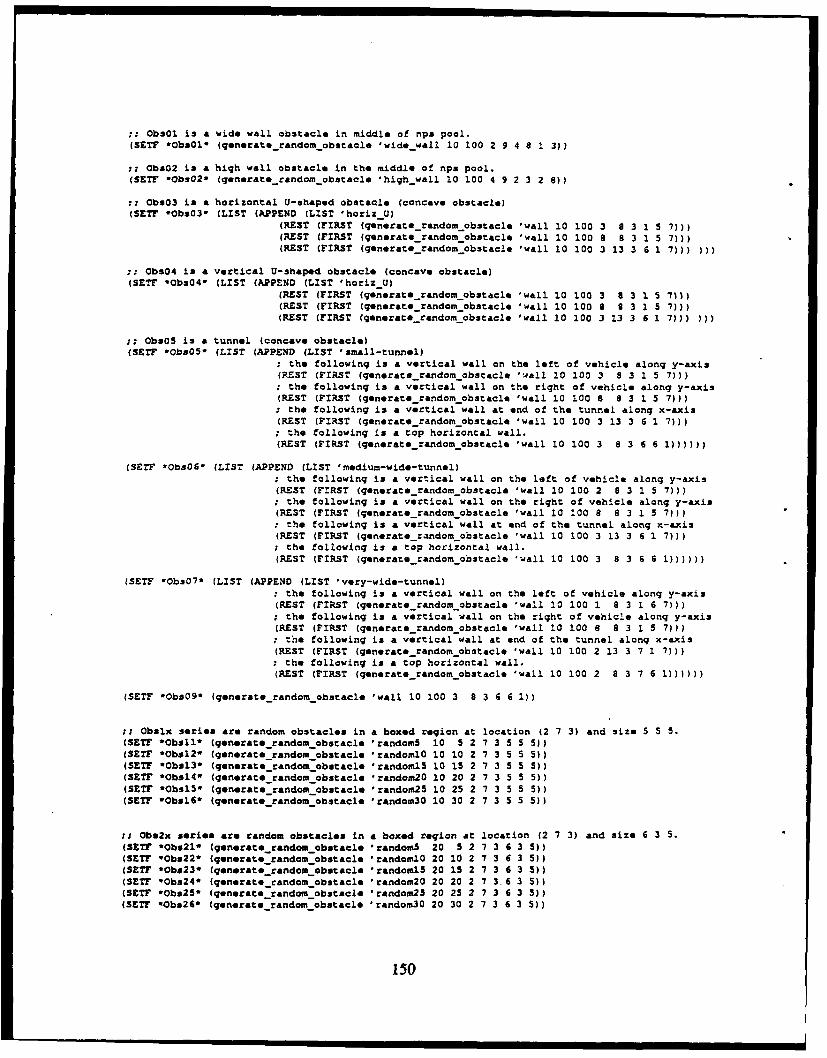
ObsOl is a wide wall obstacle in middle of nps pool.(SETF *ObsOl (generaterandom obstacle 'widewall 10 100 2 9 4 8 1 3))
: Oba02 is a high wall obstacle in the middle of nps pool.(SETT Obs02* (qenerate random obstacle 'highwall 10 100 4 9 2 3 2 8))
;: ObsO3 is a horizontal U-shaped obstacle (concave obstacle)(SETF *Obs03* (LIST (APPEND (LIST 'horiz U)
(REST (FIRST (generaterandom obstacle 'wall 10 100 3 8 3 1 5 7)))(REST (FIRST (generate random obstacle 'wall 10 100 8 8 3 1 5 7)))(REST (FIRST (generate_random obstacle 'wall 10 100 3 13 3 6 1 7))) )))
ObsO4 is a vertical U-shaped obstacle (concave obstacle)(SETF *ObsO4* (LIST (APPEND (LIST 'horiz U)
(REST (FIRST (generaterandom obstacle 'wall 10 100 3 8 3 1 5 7)))(REST (FIRST (generate random obstacle 'wall 10 100 8 S 3 1 5 7)))(REST (FIRST (generate randomobstacle 'wall 10 100 3 13 3 6 1 7))) )))
ObsO5 is a tunnel (concave obstacle)(SETF *ObsO5* (LIST (APPEND (LIST 'small-tunnel)
: the following is a vertical wall on the left of vehicle along y-axis(REST (FIRST (generate random obstacle 'wall 10 100 3 8 3 1 5 7))); the following is a vertical wall on the right of vehicle along y-axis(REST (FIRST (generaterandomobstacle 'wall 10 100 8 8 3 1 5 7))): the following is a vertical wall at end of the tunnel along x-axis(REST (FIRST (generate randomobstacle 'wall 10 100 3 13 3 6 1 7))); the following is a top horizontal wall.(REST (FIRST (generate_randomobstacle 'wall 10 100 3 8 3 6 6 1))))))
(SETF *ObsO* (LIST (APPEND (LIST 'medium-wide-tunnel); the following is a vertical wall on the left of vehicle along y-axis(REST (FIRST (generaterandom obstacle 'wall 10 100 2 8 3 1 5 7))); the following is a vertical wall on the right of vehicle along y-axis(REST (FIRST (generate random obstacle 'wall 10 100 8 8 3 1 5 7))); the following is a vertical wall at end of the tunnel along x-axis(REST (FIRST (generaterandom obstacle 'wall 10 100 3 13 3 6 1 7))); the following is a top horizontal wall.(REST (FIRST (generaterandom obstacle 'wall 10 100 3 8 3 6 6 i))))))
(SETF Obs07* (LIST (APPEND (LIST 'very-wide-tunnel); the following is a vertical wall on the left of vehicle along y-axis(REST (FIRST (generaterandomobstacle 'wall 10 100 1 8 3 1 6 7))); the following is a vertical wall on the right of vehicle along y-axis(REST (FIRST (generate random obstacle 'wall 10 100 8 8 3 1 5 7))); the following is a vertical wall at end of the tunnel along x-axis(REST (FIRST (generaterandom obstacle 'wall 10 100 2 13 3 7 1 7))): the following is a top horizontal wall.(REST (FIRST (generate random obstacle 'wall 10 100 2 8 3 7 6 1))))))
(SETF -Obs09* (generate random obstacle 'wall 10 100 3 8 3 6 6 1))
Obslx series are random obstacles in a boxed region at location (2 7 3) and size 5 5 5.(SET? *Obsll* (generate random obstacle 'random5 10 5 2 7 3 5 5 5))(SET? *Ob*12* (generate random obstacle 'randomlO 10 10 2 7 3 5 5 5))(SETF eObsl3* (generaterandom obstacle 0randoml5 10 15 2 7 3 5 5 5))(SETF *Obsl4* (generate random obstacle 'random20 10 20 2 7 3 5 5 5))(SETF #ObslS* (generaterandom obstacle 'random25 10 25 2 7 3 5 S 5))(SET? *Obsl6* (qenerate random obstacle 'random30 10 30 2 7 3 5 5 5))
; Obs2x series are random obstacles in a boxed region at location (2 7 3) and size 6 3 5.(SET? *Obs2l (generate random obstacle 'random5 20 5 2 7 3 6 3 5))(SETF *Obs22* (generate random obstacle 'randomlO 20 10 2 7 3 6 3 5))(SETF *Obs23* (generate random obstacle "randoml5 20 15 2 7 3 6 3 5))(SETF Obs24* (generate random obstacle 'random20 20 20 2 7 3,6 3 5))(SETF -Obs25* (generate randomobstacle 'random25 20 25 2 7 3 6 3 5))(SETF '0bs26* (generate random obstacle 'random30 20 30 2 7 3 6 3 5))
150
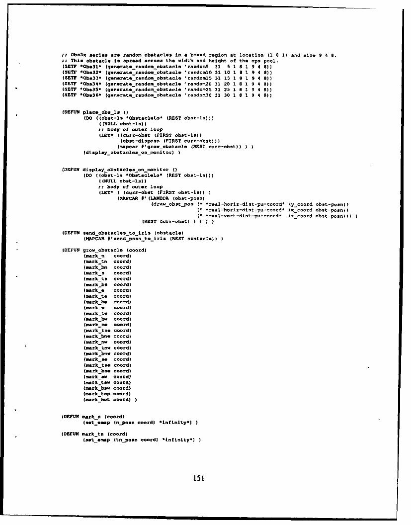
it Obs3x series are random obstacles in a boxed region at location (1 8 1) and size 9 4 8.:; Thia obstacle is spread across the width and height of the nps pool.(SETFP *Obs3l* (generate_random-obstacle 'randomS 31 5 1 8 1 9 4 8))(SET? 'Obs32* (generate-random-obstacle Irandoml0 31 10 1 9 1 9 4 8))(SET? '0bs33* (generate-random-obstacle 'randoml5 31 15 1 8 1 9 4 8))(SET? '0bs34* (generate-random-obstacle Irandom2a 31 20 1 6 1 9 4 8))(SETF 'Obs35* (generate_random-obstacle 'random25 31 25 1 8 1 9 4 8))(SET? '0b*36* (generate-random-obstacle 'random30 31 30 1 8 1 9 4 9))
(DEFUN place -obs -is 0)(DO ((obst-Is 'ObstacleLs* (REST obst-is)))
((NULL obst-lo));; body of outer loop(LET* ((curr-obst (FIRST obst-is))
(obst-disposn (FIRST curr-obst)))(mapcar *'qrow-obstacle (REST curr-obst))
(display obstacles-on-manitor)
(DEFUN display obstacles-on-monitor ()(DO ((obst-ls *ObstacleLs' (REST obst-la)))
((NULL obst-ls));body of outer loop
(LET' ( (curr-obst (FIRST obat-la))(MAPCAR * (LAMBDA (obat-posn)
(draw-obstypos ('real-horiz-dist-pu-coord* (ycoord obst-posn))(* real-horiz-dist-pu-coord' (x_coord obst-poan))(' real-vert-dist-pu-coord* (z_coord obst-posnf)
(REST curr-obst) )I
(DEFUN send-obstacles-to-iris (obstacle)(MAPCAR *'sendpoan to iris (REST obstacle))
(DEFUN grow obstacle (coord)(mark -n coord)(mark tn coord)(mark bn coord)(mrksa coord)(mark to coord)(mark bs coord)(mark a coord)(mark te coord)(mark be coord)(mark w coord)(mark tw coord)(mark be coord)(mark-ne coord)(mark tne coord)(mark-bne coord)(mark-nw coord)(mark_tnw coord)(mark-bnw coord)(mark-so coord)(mark tse coord)(mark bse coord)(mark-se coord)(mark-tiny coord)(mark bew coord)(mark -top coord)(mark-bat coord)
(DEFUN mark n (coord)(set eomap (npomn coord) 'infinity')
(DEFUN mark tn (coord)(set emap (tnposn coord) 'Infinity*)
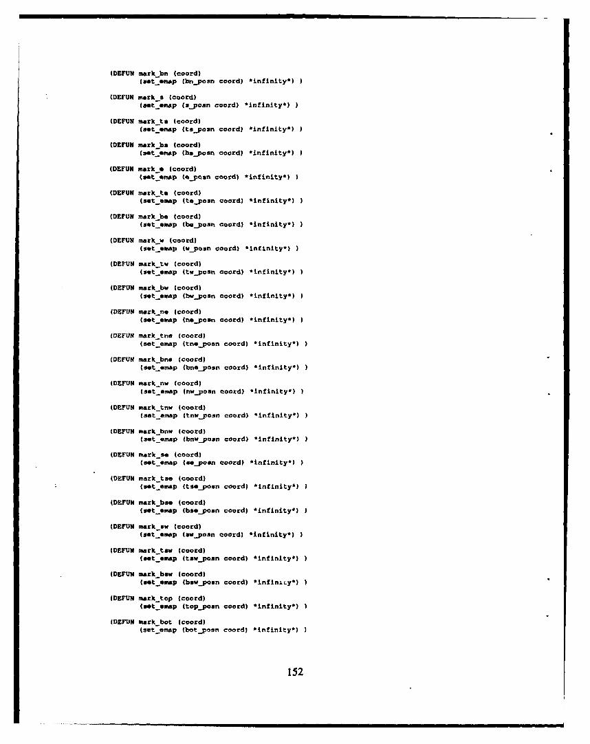
(DEFUN mork-bn (coord)(aet-omap (bnposn coerd) *infinity*))
(DEFUN mark-s (coord)(sot omap (sypoan coord) *infin~ity*)
(DEFUN mark-ts (Ccord)(sot omap (tsyposn coord) *infinity*) )
(DEFUN mark ha (coord)(set osmap (baposn coord) *infinity*)?
(DEFUN markoe (ccord)(set emap (%_posn coard) *infinity*)
(DEFUN mark-to (coard)(set-emap (topas coord) *infinity*))
(DEFUN mark-be (coord)(set emap (beporn coord) *infinity*))
(DEFUN mark-w (coord)(sot-omap (wposn coord) *infinity*)
(DEFUN marktw (coord)(9otoemap (twvjosn coord) *infinity*)
(DEFUN mtark -bw (coord)(gotoemap (bwposn coord) *infinity*)
(DEFUN mark -no (coord)(set emap (nopoan coord) *infinity*)
(DEFUN mark-tne (coord)(set emap (tnoposn coord) *infinity*)
(DEFUN mark-bno (coord)(sot omap (bnoposn coord) *infinity*)
(DEFUN marknw (coord)(set omap fnwponn coord) *infinity*)
(DEFUN mark tnw (coord)(set omap (tnwjposn coard) *infinity*)
(DEFUN mark bnw (coord)(sotoamap (bnvpoan coord) *infinity*)
(DEFUN mark-so (coord)(sot emap (xoepoan coord) *infinity*)
(DEFUN mark tao (coord)(sot emap (tsojon coard) *infinity*)
(DEFUN mark bso (coord)(sot omap (bspoan coord) *infinity*)
(DEFUN mark 3w (coard)(set eop (swpoan coord) *infinity*)
(DEFUN mark-tow (coord)(set oMap 4tswpoan coord) *infinity*))
(DEFUN mark bow (coord)(sotoemap (bswposn coord) *infinity*))
IDEFUN mark -top (coord)(sot emap (toppcsn coord) *infinity*)
(DEFUE mark bot (cord)(set omap (botposn coord) *infinity*)
152
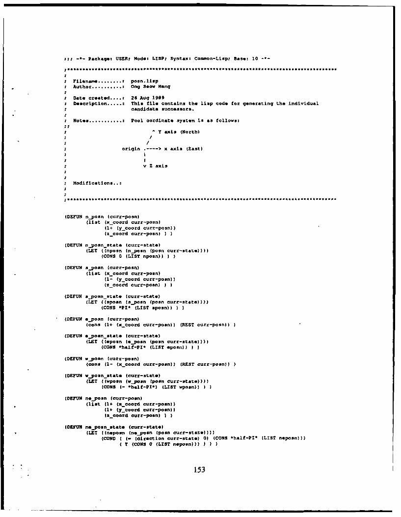
I:--Packages USER: Made: LISP: Syntax: Common-Lisp: Bas: 10 -
Filenam ... : poon.lisp*Author .............Onq Seov Meng
t Oate created .... : 26 Aug 1999;Description ........ This tile contains the lisp code for generating the individual
* candidate successor*.
Notes .............. Pool oordinato system is as follows:
Y axis (North)
*origin ----- x axis (East)
*v vZaxis
Modifications..:
(DEFUN nposn (curr-posn)(list (x_.coord curr-posn)
(1+ (ycoord curr-posn))(z_coord curr-posn)
(DEFUN nposn_state (curr-state)(LET ((nposn (nposn (posn curr-state)f)
(CONS 0 (LIST nposn)
(DEFUN sposn (curr-posn)(list (x_coord curr-posn)
(U- (ycoord curr-posn))(zcoord curr-poonj)
(DEFUN sposn_state (curr-state)(LET ((sposn (sposn 1posn curr-state))))
(CONS *PI* (LIST spoon))
IDEFUN eposn (curr-posn)(cons (1+ (xcoord curr-poan)) (REST curr-posn))
(DEFUN eposnstate Icurr-state)(LET ((eposn (eposn (posn curr-state))))
(CONS *half-PI* (LIST spoon))
(DEFUN vponn (curr-posn)(cons U1- (x_coord curr-poan)) (REST curr-posn))
(DEFUN wposn state (curr-state)(LET ((wpoan (vpoan (poan curr-statef))
(CONS (- *haif-PI') (LIST wposn))
(DEI1JN n*_posn (curr-posn)(list 41+ (x_coord curr-pon))
(1+ ly-coord curr-posn))tascoord curr-poan) )
(DEFUN noeposn state (curr-stat*)(MET ((neposn (neposn (poan curr-state)I)))
(COND ( (- (direction curr-stata) 0) (CONS *half-PI* (LIST neposn)))(T (CONS 0 (LIST naposnj))
153
(OEFUN) nwposn (curt-posnl(list (I- (x -coord curr-posn))
(1* (Y-coord curr-posn))(z-coord curt-poan)
(DEFUM nw~posn state (curr-state)(LET ((nwposn (nwvposn (posn curr-state))))
(COND (- (direction curr-state) 0) (CONS (- halt-PI') (LIST nwPo3n))T (CONS 0 (LIST nwposnf) ) )
(OSFON seosn (curt-pasn)(list (14' (x -coord curr-poan))
(1- (ycoord curr-poan))(zcoord curt-poan)
(DEFUN seposn state (curr-state)(LET ((seposn (nepoasn (posn curr-state))))
(COND (- (direction curr-state) *haif-PI') (CONS *PI* (LIST seposnl)))T (CONS *haif-PI* (LIST sepasnf) I
(DCEFUN swvponn (curr-poan)(list (1- Cx-Coord curr-pesn))
* (1- (ycoerd curt-pann))(zcootd curt-pofi)
(DEFUN swvposn state (curt-state)(LET ((swposn (sw~pasn (posn curt-state))))
(COND ((- (direction Curt-state) *P1') (CONS (- half-PI') (LIST swposn))T (CONS *PI* (LIST swpasn)))
top positions
(DEFUN? tnponn (cutt-posn)(list (x-coord curr-posn)
(1+ (y_coord curt-pasn))(I- (zcoord curt-penn))
(DEFC; tnpoun state (curt-state)(LET ((tnposn (tn~posn (poan curt-state))))
(CONS 0 (LIST tnposn))
(DEFUN tsposn (curt-pasn)(list (xcoord curr-posnl
(1- (ycoord curt-posnl)(I- (z-coord curt-posn))
(DEFUN? tsposn state (curt-state)(LET ((tsposn (tsposn (posn curt-state))))
(CONS *PI* (LIST tsposn))
(DEFt)? twvposn (curr-pomn)(list (1- (xcoord curr-psi))
(ycoord curr-posn)(1- (z-coord curt-posn))
(DEFU? twpoan state (curt-state)(LET ((Tvposn (tvposn (pasn curr-state))))
(CONS C- 'haif-PI') (LIST twposn))
(DEMt)? teposn (cutr-pasn)(list (1.4 (x-coord curr-psi))
(ycoord curt-pasnIU1- (azcootd cutr-pomn)) I
(DE~t))teposn state (curt-state)(LET ((tepan (teposn (penn curt-state))))
(CONS *half-PI* (LIST tepomnl))
154
(DEFUN tneposn (curr:-poan)(list (1+ Cx_coord curr-posn))
(1+ (ycoord curr-posn))(1- (zCoord curr-posn()
* (DEFUN tn6_p03n_3tate (CUrr-Stat*)(LET ((tnepesn (tn*_posn (poan curr-state))))
(CONO ( - (direction curr-3tat*) 0) (CONS *half-PI' (LIST tnePosn)flT (CONS 0 (LIST tneposn)))
(DEFUN tnWpo3n (curr-poan)(list (I- (x-coord curr-pesn))
(1+ ycoord curr-posn))(1- (zcoerd curr-posn))
(DEFUN tnwpo3n_3tate (curr-3tate)(LET (Ctnwposn tnwaposn (poan curr-state)'fl)
(COND ( (- (direction curr-stato) 0) (CONS (-*half-PI'*) (LIST tnwpesn))(T (CONS 0 (LIST tnwposn)) I
(DEFUN tse uosn (curr-posn)(is;t (1+ (x-coord, curr-posn))
(1- Cy-coord curr-posn))(1- (zcoord curr-pasn))
(OEFtXN t3OeposnState (curr-utate)(LET C(t3*pOmn (t3SeyOsn (pasn curr-state)
(CONO C - (direction curr-stat.) *half-?I*) (CONS *P1 (LIST tsepoan)))T (CONS *halt-PIe (LIST tseposnf))
(DEFUN tswposn (curr-posn)(list (I- (xcoord curr-pasnl)
(1- (ycoord eiurr-pasn))(1- (zcoord curr-posn))
(DEFUN t3Wposnstate CcUrr-state)(LET ((tsWPOSn (tsWposn (posn curr-state)f)
(COND ( (- (direction curr-state) *Pl) (CONS C-*half-PI*) (LIST t3WZosn()(T (CONS *PI* (LIST tswposn)))
Bottom positions
(DEFVl4 bnpvosn (curr-posn)(list (xcoord curr-posn)
(1+ (ycoord curr-poan)(1+ (zicoord curr-posn))
(DEFUN bn~pomn stat* (curr-3tate)(LET ((bnpomn (bnposn (posn curr-state))C)
(CONS 0 (LIST bnpasn))
(DEMU bSposn (curr-posn)(list (x-coord curr-poon)
C1- (yc.oord curr-posn))(2+ (zcoord curr-poon))
(DEFUN bSp02nState (CUrC-5tate)-(LET ((bsposn (bsposn (posn curr-stat*)
* (CONS *PI* (LIST bspoan)))
(DEFtTN bwposn (curr-poa )(list (1- (xcoerd curr-pogn))
(ycoord clarr-poon)(1+ (z-coord curr-posn)))
(DEFUN bwposn state (c1urr-state)(LET ((bvposn (bwposn (posn curr-state))))
(CONS (- *half-fl*) (LIST bwposn))
155
(DEFUN beposn (cur:-pasn)(list (14+ (x -coord curt-pain))
fycoard cufr-Pan)(1+ (z-coord curt-pain))
(DEFUN beposn state (curr-3tatO)(LET (lbopoan (beposn (poan curr-stat.))))
(CONS *half-PI' (LIST beposn))
(DEFUN bneposn (curr-Pain)(list (1+ (x-coord curt-pain))
(1+ (y_coord curt-pain))(1+ (z-coord curt-pain)))
(DEFUN bneposn state (curt-state)(LET (Cbnepasn (bn*_pasn (poan curt-state))))
(COND ( (- (direction curr-state) 0) (CONS *half-PI* (LIST bneosn)))(T (CONS 0 (LIST bnOposn)))
(DEFUN bnWposn (curr-posn)(list U1- (xcoord curr-posn))
(1+ (ycaard curr-pa3n))(1+ (z-coord curt-pain))
(DEFUN bnwposn state (curr-state)(LET ((bnwpasn (bnwposn (pain curr-state)f)
(COIJO ( (- (direction curr-state) 0) (CONS (- half-Pl*) (LIST bnWOasn))(T (CONS 0 (LIST bnwpogn)))
(DEFUN bsepasn (curt-pasn)(list (1+ Cx_coord curr-pan))
(1- (y_coord curr-pasn))(1+ Cz-coord curr-pan))
(DEFUN bieposnstate (curt-stat.)(LET ((biepoin (bs*_pasn (pain curt-state))))
(CONO (C- (direction curt-state) *haif-?I*) (CONS *PT' (LIST bseposnf)T (CONS 'half-Pl' (LIST bsepain)))
(DEFUN bsWpasn (curt-pan)(list (1- (x-coard curt-pain))
(1- (y_coord curt-pan))(1+ (Scoard curr-posn))
(DEFUN bSWpa3nState (curr-state)(LET ((bsWPasn (b3Wpasn (pain curt-state))))
(CONO (- (direction curt-state) 'PT'*) (CONS (-half-PI') (LIST bswoosn))T (CONS *PI* (LIST bawpoan)))
(DEFUN tappasn (curt-pain)(list (x -coatd curt-pan)
(Y-coord curt-pain)(1- (zcoord curt-pain))
(DEFUN topposnstate (curt-state)(LET ((toppoin (toppoan (pow% curt-state))))
(CONS (direction curt-stat.) (LIST topposni)
(DEFUN botposn (curr-pain)(list (x -caotd curt-poon)
(y-coord curt-pain)(1+ (icoard curt-pan))
(DEFUN bot~posn state (curt-state)(LET ((batpan (btpain (pain curt-state)))(CONS (direction curr-state) (LIST botPoin))
156
-*- Packaqe: USER; Mode: LISP: Syntax: Common-Lisp; Sase: 10
..........*5* * ........................
Filename ....... : succ.lispAuthor ......... Onq Seow Mang
Date created...: 21 Dec 1989Description .... : This file contains the lisp functions that creates a list of
candidate successors. This successor list is a function of thevehicle headinq.
Modifications..:
(DEFUN fwd dive succlist (curr-state)returns list of forward candidate successorsin the x-y plane, in the current direction.
(LET* ((curr-dir (direction curr-state))
(dir-q (dir_quantum curr-dir))(COND ((rangep dir-q -0.5 0.5) (fwd divesuccO_list curr-state))
((ranqep dir-q 3.5 4.5) (fwd dive_succ4_list curr-state))((OR (rangep dir-q -8.1 -7.5) (rangep dir-q 7.5 8.1))
(fwd dive_succ8_list curr-state))
((rangep dir-q -4.5 -3.5) (fwd dive succl2 list curr-state))
(DEFUN fwdrise-succ-list (curr-state)returns list of forward candidate successors above the curren: posnin the x-y plane, in the current direction.
(LET* ((curr-dir (direction curr-state))(dir-q (dir_quantum curr-dir))(COND ((rangep dir-q -0.5 0.5) (fwd rise_succO_list curr-state))
((rangep dir-q 3.5 4.5) (fwdrise succ4_list curr-state))((OR (rangep dir-q -8.1 -7.5) (rangep dir-q 7.5 8.1))
(fwd rise succS list curr-state))((rangep dir-q -4.5 -3.5) (fwdrise succl2 list curr-state))
(DEFUN fwd-level-succ list (curr-state)returns list of forward candidate successorsin the x-y plane, in the current direction.
(LET* ((curr-dir (direction curr-state))
(dir-q (dirquantum curr-dir))(COND ((ranqep dir-q -0.5 0.5) (fwdlevel succO list curr-state))
((rangep dir-q 3.5 4.5) (fwd levelsucc4 list curr-state))
((OR (rangep dir-q -8.1 -7.5) (rangep dir-q 7.5 8.1))(fwd level_succ8 list curr-state))
((rangep dir-q -4.5 -3.5) (fwd level succl2_list curr-state))
(DEFUN fwd_rise_andlevelsucc_list (curt-stace)returns list of forward rise and level candidate successors
;; in the x-y plane, in the current direction.(APPEND (fwd rise succ list curr-state) (fwd level-succ-list curr-state))
(DEFUN fwd dive and level succ list (curr-state)
returns list of forward dive and level candidate successorsin the x-y plane, in the current direction.
(APPEND (fwd.dive succ lis- -urr-state) (fwd levelsuccli.t curr-state))
57
(DEFtJN top Nwd ri succ-list (curr-state)returns list of top forward left and right candidate successorsin the x-y plan., in the current direction.
(LET* ((curr-dir (direction curt-state))(dir-q (dir quantum curr-dir))
(CONO ( (ranqep dir-q -0. 5 0. 5) (LIST (tneposn state curr-state)(tnwpyosnstate curr-state)
((ranqep dlr-q 3.5 4.5) (LIST (tn0_posnstate curr-state)(tse~posn state curt-state)
((OR (rangep dir-q -8.1 -7.5) (rangep dir-q 7.5 8.1))(LIST (tseposnstate curr-state)
(tsWposnstate curr-state)((rangep dir-q -4.5 -3.5) (LIST (tnw~posn~state curt-state)
(t3W~pCsnstat. CUrr-scatte) )
(DEFUN bot fwd-rl succli st (curt-state)returns list of top forward left and right candidate successorsin the x-y plane, in the current direction.
(LET* ((curt-dir (direction curr-state))(dir-q (dir quantum curt-dir))
(CCNO ((rangep dir-q -0.5 0.5) (LIST (bneposnstate curr-state)(bnwposn state curt-state) I
((ranqep dir-q 3.5 4.5) (LIST (bn%*posnstate curr-state)(bse..posn state curt-state)
((OR (rangep dir-q -8.1. -7.5) (rangep dir-q 7.5 8.1))(LIST (b30_posn state curt-state)
(baw uosnastat. curr-state)((rangep dir-q -4.5 -3.5) (LIST (bnw posn stat. curr-state)
(bswposn state curt-state) )
(DEFUN top ri succ list (curr-state)returns list of top left and right candidate successorsin the x-y plane, in the current direction.
(LET* ((curr-dir (direction curr-state))(dir-q (dir quantum curt-dir))
(COND ((ranqep dir-q -0.5 0.S) (LIST (tf*_posnstate curr-State)(twposnstate curr-state)
((ranqep dir-q 3.5 4.5) (LIST (tnposn state curt-state)(tasposnstate curt-state)
((OR (ranqep dir-q -8.1 -7.5) (ranqep dir-q 7.5 8.1))(LIST (te~posn state curt-state)
(twposn state curt-state)((rangep dir-q -4.5 -3.5) (LIST (tntposnstate curt-state)
(t3sposn state curt-state)))))
(DEFUN botrlsucclist (curt-state)returns list of bottom right and left candidate successors.in the x-y plane, in the current direction.
(LET* ((curr-dir (direction curt-state))(dir-q (dir quantum curr-dir))
(COND ((rangep dir-q -0.5 0.5) (LIST (beposnstate curt-state)(bwe~posn-state curt-state)
((rangep dir-q 3.5 4.5) (LIST-(bn~posn state curr-state)(bsposn state curt-state)
((OR (rangep dir-q -8.1. -7.5) (rangep dir-q 7.5 8.1))(LIST (be~posn~stata curt-state)
(bw~posn state curr-state)((rangep dir-q -4.5 -3.5) (LIST (bnposns3tate curt-state)
(ba~posn state curt-state)))
158
(OEFUN right).eft suce list (curr-state)returns list of right and left candidate successorsin the x-y plane, in the current direction.
(LET, ((cu::-dir (direction curr-stat*))(dir-q (dir quantum curr-dir))
(COND ((ranqop dir-q -0.5 0.5) (LIST foepasn state curr-state)(wposn szate curr-state)
((rangep dir-q 3.5 4.5) (LIST (n~posnstate curr-state)(3_posn state curr-state)
((OR trangep dir-q -8.1. -7.5) (rangep dir-q 7.5 8.1))(LIST (e~posn state curr-state)
(wvposn state curr-state)(Cranqep dir-q -4.5 -3.5) (LIST (nposnstate curr-state)
(sposn_ state curr-*tate)))
(DEFUN top all succ list (curr-state)returns list of right and left candidate Successors
-. In the x-y plane, in the current direction.(LET- ((curr-dir (direction curr-state))
(dir-q (dir quantum curr-dir))(COND ((rangep dir-q -0.5 0.5) (LIST (teposn state curr-state)
(twoosn_state curr-state)(top posn state curr-scate)
((rangep dir-q 3.5 4.5) (LIST (tnposn-state curr-state)(tsposn state curr-state)(top posn state curr-state)
((OR (rangep dir-q -8.1 -7.5) (rangep dir-q 7.5 8.1))(LIST (teposnstate curr-state)
(twpoan stat* curr-state)(topposn state curr-state)
((rangep dir-q -4.5 -3.5) (LIST (tnposn state curr-state)(ts posnstate curr-state)(topposn state curr-state)))
(DEFUI bot_all_succ list (curr-state)returns list of right and left candidate successorsin the x-y plane, in the current direction.
(LET* ((curr-dir (direction curr-state))(dir-q (dir_quantum curr-dir))(COND ((rangep dir-q -0.5 0.5) (LIST (beposn state curr-stato)
(buposn state curr-state)(botposnState curr-state)
((rangep dir-q 3.5 4.5) (LIST (bnposn state curr-state)(bsposn state curr-state)(botposn state curr-state)
((OR (ranqep dir-q -8.1 -7.5) (ranqep dir-q 7.5 8.1))(LIST (be posn state curr-state)
(bwposnstate curr-state)(botposn state curr-state)
((ranqep dir-q -4.5 -3.5) (LIST (bnposn state curr-state)(bsposn state curr-state)(botposn state curZ-state))))
59
(DEFUN top all end rl suco list (curr-state)returns list Of right and left candidate successorsin the x-y plane, In the current direction.
(LET* ((curr-dir (direction clrr-state))(dir-q (dir _quantum curr-dir))
(COND ((ranqep dir-q -0.5 0.5) (LIST (eposns3tate curr-state)(wposn state curr-state)(teP03sstate curr-state)(twvpoxn_3tate curr-state)(tOppOsn state curr-state))1
((rangep dir-q 3.5 4.5) (LIST (nposnstate curr-state)(sposnstate curr-state)tnposn _state curr-state)(tsposn _state curr-state)(toppoan state curr-state))
((OR (range; dir-q -8.1 -7.5) (range; dir-q 7.5 8.1))(LIST (eposn state curt-state)
(WPosn state curt-state)* (teosn state curt-state)
(tv-posp-stat& curt-state)(topposnstate curr-state)
((range; dir-q -4.5 -3.5) (LIST (nposnstate curr-state)(Sp03n state curr-state)(tnpo2nstate curr-state)(ts-posn stat. curt-state)(topposn state curr-state) )
(DEFUI bot all-and rl-succ-list (curr-state)returns l1ist of right and left candidate successors
,in the x-y plane, in the current direction.(LET* ((curr-dir (direction curr-state))
(dir-q (dir quantum curr-dir))(COND ((range; dir-q -0.5 0.5) (LIST (eposn_3tate curr-state)
(w~posn_.state curr-state)(beposnstate curt-state)(bwposn state curt-state)(botposn state ciirr-state)
((rangep dir-q 3.5 4.5) (LIST (nposnstate curt-state)(sposn state curr-stats)(bnposn state curr-state)(bsposnstate curt-state)(botposn state curt-state) )1
((OR (rangep dir-q -8.1 -7.5) (range; dir-q 7.5 8.1))(LIST (*_poan stato curt-state)
(wvposn state curr-state)(beposn state curr-state)(bwvposn state curr-state)(botposn-state curr-state)
((rang.; dir-q -4.5 -3.5) (LIST (nposnstate curt-state)(sposn _state CUrr-state)(bnposn state curr-state)(bsposnstate curr-state)(botpasn-state curr-state) )
(DEFUN back up succ list (curr-state):returns list of all candidate successors behind the curt-state.
in the x-y plane, in the current direction.(LET* ((Curr-dir (direction curt-state))
(dir-q (dir _quantum curr-dir))(COND (tranqep dir-q -0.5 0.5) (back up succO list curr-state))
((range; dir-q 3.5 4.5) (back_up succ4-list curr-state))((OR (range; dir-q -8.1 -7.5) (rangep dir-q 7.5 8.1))
(back up succ8 list curr-state))((rang.; dir-q -4.5 -3.5) (back up succl2_list curr-state))
160
(OEFUN fwd top succe list (curr-state);: eturns the one and only forward top candidate successorsin the x-y plane, in the current direction.
* (LET* ((curt-dir (direction curt-state))(dir-q (dir _quantum curr-dir))1MCOND ((ranqep dir-q -0.5 0.5) (LIST (tnposn state curr-state)))
((ranqep dir-q 3.5 4.5) (LIST (teposn_ state curr-state)))((OR (ranqep dir-q -8.1 -7.5) (ranqep dir-q 7.5 8.1))
* (LIST (tsposn state curr-state))((ranqep dir-q -4.5 -3.5) (LIST (twposn state curt-state)))))
(DEFUN fwd bet suclist (curr-state):returns the one and only forward bottom candidate successor:in the x-y plane, in the current direction.
(LET* ((curt-dir (direction curt-state))(dir-q (dir quantum curr-dir))MCOND ((ranqep dir-q -0.5 0.5) (LIST (bnposn state curr-stateflj
((ranqep dir-q 3.5 4.5) (LIST (beposn.state curt-state)))((OR (rangep dir-q -8.1 -7.5) (ranqep dir-q 7.5 8.1))
(LIST (bs~posn state curt-state))((ranqep dir-q -4.5 -3.5) (LIST (bwposn state curr-state))) I
(DEFUN fwd dive succO list (curt-state)(LIT (bnosn state curt-state)
(bnoeposn state curt-state)(bnwposn state curr-stat*) )
(DEFUN fwd dive_succ4_list (curr-state)(LIST (bne..posn state curt-state)
(beposn state curt-state)(bsoeoosnstate curt-state))
(DEFUN fwd dive succS list (curr-state)(LIT (bseposn state curt-state)
(bsposn state curt-state)(bswposn state curt-state)
(DEFUN fwd dive succl2_list (curt-state)(LIT (bsvposn_state curt-state)
(bwposn state curt-state)(bnwposn state curt-state)
(DEFUI fwd rise succO list (curt-state)(LIST (tnposn state curt-state)
(tn*_.poan-state curt-state)(tnvposn state curt-state)
(DEFUN fwd rise succ4_list (curt-state)(LIST (tn*_posn state curr-state)
(teposn state curt-state)(tse.poan state curr-state)
(DEFUN fwd-rise succ8_list (curt-state)(LIST (tseposn state curt-state)
(tsaposn state curr-state)(tswpsnstato curt-state)
(DEFU fwd rise succl2 list (curt-state)(LiT (tsw-poznstate cur-state)
(tw-posnestate curt-state)(tnwposn state curt-state)
(DEFUN fwd-level succ0_list (curt-state)-(LIST (nposn state curt-state)
(neposn state curt-state)(nwposn state curt-state)
161
(DEFUN fwd level succ4 list (curr-state)(LiST (noeposn s;tat* curr-statet)
(e-posn -state curt-state)(s*_posn state curt-state)
WVZFUN fwd level succ@lIist (curr-state)(LiST (seposn ';tat* curr-state)
(sposn state curt-state)(sw-posn -state curt-state)
(IDEFUN fwd level succ12 list (curr-State)(UST (SWpoasn state curt-state)
(v-Posn state curt-state)(nwuposn ~state curt-state)
(DEFU?4 backup-succOjlist (curt-state)(LIST (sposn state curt-state)
(so-posn state curt-state)(swyposn state curt-state)(tsposr_state curt-state)(tse-posn-state curt-State)(tsvpoan-stato curt-state)(bs.Josn state curt-state)(bseposn state curt-state)(bsw~posn state curt-state)
(DEFUlI back up succ4_list (curr-state)(LIST (nwvposn state curt-state)
(sw-posn state curt-state)(v-posn state curt-state)(trnw~posnstato curt-state)(tswvposnstate curt-state)(tw-pesn state curt-state)(bnwvposn state curt-state)(bswvposn state curt-state)(bwposn_state curt-state)
(DEFUN back-up-succO_list (curt-state)(LIST npoan state curt-state)
(n*_posn state curt-state)(nw-posn-state curt-state)(tnposn~state curt-state)(tneposnstate curt-state)(tnw~posn state curr-state)(bniposq_state curt-state)(bnepoxn state curt-state)(bnvposn state curt-state)
(DEF'UN back up succl2_list (curt-state)(LIST (neposn state curt-state)
(saeposn state curt-state)(eposfi state curt-state)(tneposn state curt-state)tseposn state curt-state)
(teposfi state curt-state)(bno~pasn state cur-state)(bsoeposn _state curt-state)(beposn _state curt-state)
162
(DEZfl 30Dfwd-sucelist (curr-state)returns list of all forward candidate
* ;~ successors in the current direction.(LET* ((curr-dir (direction curr-state))
(dir-q (dir quantum curr-dir)(CONO ((ranqep ditr-q -0.5 0.5) (3D-succOjIist curr-state))
((rangep d~tr-q 3.5 4.5) (3Dsucc4 list curr-state))* ((OR (ranqep dir-q -8.1 -7.5) (rangep dir-q 7.5 8.1))
(3D succOIlist curr-state))((ranqep dir-q -4.5 -3.5) (3D-succl2list curr-state))
(DEMU 3D-succO list (curr-state)(LIST (nposn-state curr-state)
(ne~peanatate curr-state)(nwposn state curr-state)(tnposnstate curr-state)(tnoeposn state curr-state)(tnv~pasn state curr-2tAte)(bnposn sxtate curr-state)(bn*_yosn state curr-state)(bnw posn state curr-stato)
(DEFUN 3D-3ucc4 list (curr-state)(LIST tnepcxn state curr-state)
(epoun state curr-state)(s-poasn-state eurr-state)(tne~posn state curr-state)(teoasn state curr-state)
4 (tseposns3tatO CUrr-2tate)(bneposn state, curr-state)(beposn-state curr-state)(bsposn state curr-stace)
(DEFUN 30 succSlist (curr-state)(LIST (seyposns3tate curr-stato)
(sposn state curr-state)(svposn state curr-stat*)(tse.posnstate curr-state)(ts-posn state curr-state)(tsw~posnstate curr-stato)(bseposn state curr-state)(bsposnstate cirr-state)(bswpomsn state curr-state)
COFFUN 3D-succl2 list (curr-stat.)(LIST (swvposn-,1 ate curr-state)
(wpoan state curr-state)(nwpoan state curr-stato)(tsvposnstato curr-state)(twvposnstate, curr-state)(tnwvpoan state curr-state)(bswvpoan state clrr-state)(bwposnstote curr-state)(bnwoan state curr-state)
163
-- Mode: LISP; Syntax: Common-lisp, Package: USER--
Filnam e . ...: syin-iris-coswns.lisp
Modifications:26 Feb 90 1. Changed the following port numbers due to IRIS OS Upgrade:
*remote-portl* 1052*remote-port2* 1051
:"Talk" in an object to send and to receive data across a network.
usage (send talk :init-destination-host iris2) ; get remote host object*(send talk :start-iris) ; make connection*(send talk :put-iris data) ; send data
(send talk tget-iris) ; get data from remote host*(send talk zstop-iris) ; Clos0 communication*(send talk xreuse-irisl ; open closed communication*(send talk schange-iris-ports) ; switch from iri92 full-duplex
;comm3 to irisS semi-duplex
(defvar talk)
;library functions to be used by flavor conversation-with-iris.
(defmacro loopfor (var mnit test expl)(prog 1)
(setq *var *init)tag
expl(setq *var (1+ *var))(if (- .var *test) (return t) (go tag)
(defun convert-number-to-string (n)(princ-to-string n))
(defun convert-string-to-integer (str &optional (radix 10))(do ((j 0 (+ j 1))
(n 0 (+ (* n radix) (digit-char-p (char str J) radix))))((j (length str)) n)))
(defun find-period-index (str)(catch 'exit
(dotimes (x (length str) nil)(if (equal (char str x) (char ". 0))
(throw 'exit xM))
(defun get-leftaide-of-real (str &optional (radix 10))(do M( 0 (1+ J))
(n 0 (+ (a n radix) (digit-char-p (char str J) radix)((or (null (digit-char-p (char str 1) radix)) (- j (length str))) n)))
(defun get-rightside-of-real (str &optional (radix 10))(do ((ndex (I+ (find-period-index str)) (1+ index))
(factor 0.10 (Cfactor 0.10))(n 0.0 (+ n (Cfactor (digit-char-p (char str index) radix))
((- index (length atr)) n )))
(defun convert-string-to-real (str &optional (radix 10))(+ (float (get-leftside-of-real str radix)) (get-rightaide-of-real str radix)))
164
*port number definitionst Iris2 use* full duplex comms so ports are set up for* this default. Iris5 uses semiduplex coimma (the same port for send and
receive) and will have both ports set to *remote-portl*.
gThe following port numbers, *remote-portl* and *remote-port2** ::has been changed due to IRIS OS upgrade.
i (defvar *remoto-portl* 1027) ; this is the remote send port;;(defvar *remote-port2* 1026) ;this is the remote receive port(defvar *remote-portl* 1052) ; this is the remote send port(defvar *remote-port25 1051) ; this is the remote receive port
(defvar *local.talk-port* 1500) ; this is the local send port(defvar *local-listan-port* 1501) ;this is the local receive port
ISET? *remote-portl* 1052) ; this is the remote send port(SET? *remete-port2* 1051) ; this is the remote receive port(SET? *local-talk-port* 150 : this is the local send port(SETIP *local-listen-port* l50oj. this is the local receive port
conversation-with-iris flavor definition
*This definition is not restricted to iris, but it can be*used with any host as long as the remote host does not*already use ports 1027 or 1026 for its own purposes.
(defflavor conversation-with-iris ((alking-port-number *remote-portl*)*(listening-port-number *remote-part2*)
(local-talk-port-number *local-talk-port*)(local-2istn-prt-number *local-listen-port*)(talking-stream)(listening-stream)(destination-host-object)
0)initable-instance-variables)
(defmethod (:init-destination-host conversation-with-iris)(name-of-host)
(aetf destination-host-object (net :parse-host name-of-host)))
(defmethod (:change-iris-ports conversation-with-iris)
0)(aotf talking-port-number *remote-portl*) ;sets iris5 semi-duplex cormi ports.(*etf listeninq-port-number *remote-portl*))
(dofmethod (:start-iris conversation-with-iris)0I
(setf talking-stream(tcp: open-tep-stretam destination-host-object
talking-port-numberlocal-talk-prt-number))
(setf listening-stram(tcp: open-tcp-stream destination-host-object
listenin-port-numberlocal-listen-port-number))
(terpri)(princ "A conversation with the Iris machine has been Initiated.')(terpri))
165
(detmethod (:reuse-iris convrstion-with-iris)0)
(send self :start-iris))
(defun read-string (stream num-chars)(let ((out-string -"))
(dotimes Ui num-cihars)(setf out-string (string-append out-string (read-char stream))))
out-string))
(defmothod (iget-iris conversation-with-iris)1)
(let* ((typebuffer(lenqthbuffer
* (buffer -
(buffer-length U)(progn
(setf typebuffer(read-string listening-stream 1))
(setf lengthbuffer(read-stri.q listening-stream 4))
(setf buffer-length(convert-string-to-integer longthbuffer))
(setf buffer(read-string listening-stream butter-length))
(cond ((equal typebuffer "I) (convert-string-to-integer buffer))((equal typebuffer "R") (convert-string-to-real buffer))((equal typebuffer "C") buffer)(t nil)))))
(defvar *step-var* 0)
(defun my-write-string(strinq stream)(let* ((nun-chars (length string)))
(dotimes Ui num-chars)(write-char (aref string i) stream)
(detmethod (:put-iris convrstion-with-iris)(object)
Clet* ((buffer (cond((equal (type-of object) 'bignum) (convert-number-to-string object))((equal (type-of object) Ifixnum) (convert-number-to-string object))((equal (type-of object) * single-float) (convert-number-to-string object))((equal (type-of object) 'string) object)(t "error")))
(buffer-length (length buffer) )-
(typebuffer (cond ((equal (type-of object) 'bignum) "I)((equal (type-of object) 'fixnum) "I)((equal (type-of object) 'single-float) "R")((equal (type-of object) 'string) 'C")(t *C))
(longthbuffer (convert-number-to-string buffer-length)))
166
(progn(my-write-string typebuffer talking- stream)(send talking-stream :forc*-output)
(if (- (lenqth lengthbuffer) 4)(write-string lenqthbuf fer talking-stream)(proqn
(loopfor 'step-var' (length lengthbuf fez) 4(write-string O0 talking-stream))
(my-rite-strinq lengthbuf fer talking-stram)
(send talking-stream sforce-output)
(my-writ-string buffer talking-stream)(send talking-stream :force-out-put)
(defmethod (:stop-iris conversation-with-iris)
(progn (send listening-stream :close)(send talking-stream :clos*))
* (terpri)(princ "A conversation with the iris machine has been closed.")(terpsi))
* (setf talk (mak-instance 'conversation-with-iris))
(defun choose-iris ('ost-name') ;use this function when selecting comms(cond ;from the keyboard
((equal 'host-name' 'iris?)(setq 'host-name' liris2)(send talk :init-destination-host 'host-name') ;us* iriz2 as default output.(terpri)(princ "Iris2 communications selected.")(terpri))
((equal 'host-name' 'irisS)(setq 'host-name* 'irisS)(send talk schange-iris-ports) ;select semi-duplex coma ports.(send talk :init-destination-host 'host-name*)(terpri)(princ ZIrisS commnunications selected.")(terpri))))
(defun select-iris? () ;use these two functions when using(setf 'host-name' 'iris?) ;the mouse-driven control pan*!.
* (send talk sinit-destination-host 'host-name')(terpri)(prino !Iri*2 commncations selected from Control Panel.")(terpri))
(defun select-irisSO((setf 'host-name' 'iris5)(send talk :init-deatination-host 'host-name')(terpri)(princ *ZrisS comunuications selected from Control Panel..)(terpri))
167
(defun start-con()(send talk :start-iris))
(defun get data((send talk :qet-iria))
(defun send float (sinqle-float)(send talk :put-iris single-float))
(defun send String (string)(send talk sput-iris string))
(defun *nd-con()(send talk :stop-iris))
(defun restart(0(send talk :reuse-iria))
16~8
-- Package: KEE; Mode: LISP: Syntax: Common-Lisp; Baset 10--
*Filename ... : mission3.lisp*Autho r .... : Ong Seov Meng
Date Created..: 20 Jan 90Description... : Contains the methods referenced by the following UNITS in
the HPES knowledge base.* (UNIT]I- (MISSIONS I* [UNIT]-(TRANSIT.POOL]* (UNZT]-(NPS.POOL)
* (UNITJ-(OPS.ORDERS]
*Modifications.:
NPS.POOL UNIT methods
INIT_-OBSTACLES method is for (unit::slotj-(NPS.POOL::init-obstacles)
(DEFUN init obstacles (THISUNIT);This method is to be activated OFFLINE and only ONCE to set the values.
(REMOVE.ALL.VALUES Inpa.pool 'obs~l)(REMOVE.ALL.VALUES 'nps.pool 'obs02)(RE.MOVE.ALL.VALUES Inps.pool * obs03)(REMOVE.ALL.VALUES 'nps.pool 'ob904)(REMOVE.ALL..VALUES Inps.pool ocbsOS)(REMOVE.Al.L.VALUES Inpa.pool 'obsD6)(REMOVE.ALL.VALUES Inpu.pool 1obsO7);;(REMOVE.ALL.VALUES Inps.pool 'ob3OO)
(REMOVE.ALL.VALUES 'nps.pool 'obsil)(REMOVE.ALL.VALUES 'npa.pool lob3l2)(REMOVE.ALL.VALUES Inps.pool 'obsl3)(REMOVE.ALL.VALUES 'npo.pooi 'obsl4J(RENOVE.ALL.VALUES Inps.pool 'obsiS)(RENOV.ALL.VALUES 'npa.pool 'ob3l6)(REMOVE.ALL.VALUES 'npa.pool lobs2l)(REHOVE.ALL.VALUES 'nps.pool lobs22)IRENOVE.ALL.VALUES 'npa.pool lobs23)(REMOVE.ALL.VALUES 'npa.pool lobs24)(REMOVE.ALL.VALUES 'npa.pool 'obs25)(REMOVE.ALL.VALUES Inpa.pool loba2E)(REMOVE.ALL.VALUES Inps.pool 'obs3l)(REMOVE.ALL.VALUES Inpa.pool lobs32)(RELOVE.ALL.VALUES Inps.pool 'obs33)(REMMV.ALL.VALUES 'npa.pool 'obs34)(REMOVE.ALL.VALUES Inpa.pool 'obs35)(REMOVE.ALL.VAWUES 'npa.pool 'obs3E)
(PUT.VALUE Inpa.pool 'obs~l. USER::*Obs~l*)(PUT.VALUE 'npa.pool 'obsO2 USER:z'0bs02
01
(PUT.VALUE Inpa.pool 'ob903 USERs:*ObsO3*)(PUT.VALUZ Inpe.pool 'obsO4 OSER::*ObsO4*)(PUT.VALUE 'npa.pool lobOs0 USE.Rst*ObsO5*)(PUT.VALUE 'npa.pool 'obsO6 USER: :*ObsO6*?
(PUT.VALUE 'npa.pool 'obsOV USERs:*ObsO7*)(PUT.VALUE Inps.pool 'obs0fi USER::,*ObsOS*)
(PUT.VALUE 'npa.pool 'obsil OSERt:*Obsll~)(PUT.VALUE 'np.9.pool lobsl2 USER: :*Obsl2*)(PUT.VALUE Inpa.pool lob913 USER: :*Obsl3*)(PUT.VALUE * nps.pool 'obsl4 USER: :*Obsl4*)
169
(PUT.VALUE 'nps.pool 'obsIS USER:*,ObslS-)(PUT.VALUE 'nps.pool "obs16 USER::-Obsl6-)(PUT.VALUE "nps.pool 'obs21 USER::*Obs21
-)
(PUT.VALUE 'nps.pool 'obs22 USER::-Obs22-)(PUT.VALUE 'nps.pool lobs23 USER:z'Obs23*)(PUT.VALUE 'nps.pool 'obs24 USER::*Obs24*)(PUT.VALUE 'nps.pool 'obs25 USER::-Obs25')(PUT.VALUE Inps.pool lobs26 USER::*Obs26*)(PUT.VALUE "nps.pool 'obs3l USER::-Obs3l-)(PUT.VALUE 'nps.pool "obs32 USER::*Obs32-)(PUT.VALE "nps.pool 'obs33 USER::.Obs33-)(PUT.VALUE 'nps.pool lobs34 USER::*Obs34-)(PUT.VALUE 'nps.pool 'obs35 USER::-Obs35-)(PUT.VALUE 'nps.pool 'obs36 USER::'Obs36-)
--- - ----- --- -- ---i ---- - - - ---- -- ---- - ----------fn f fmn amiS Sn
PANELS UNIT methods
RESETSCREEN method is for [unit::slot]-(PANELS::reset-screen)-- called by Cunit::slot].[EXECUTOR::abort-mission].
(DEFUN resetscreen (THISUNIT)(UNITMSG 'viewport-auv.scatus.panel.2 'close-panel!)(UNITMSG 'viewport-mission.status.panel.13 'close-panel!)(UNITMSG 'viewport-execute.abort.panel.16 'close-panel!)
(UNITMSG 'enter-parameters-prompt 'close!)(UNITMSG 'viewport-transit.pool.l 'close-panel!)
(UNITMSG 'viewport-user.prompt.panel.3 'open-panel!)(UNITMSG 'select-mission-prompt 'open!)(UNITMSG 'viewport-select.mission.panel.5 'open-panel!)
TRANSIT.POOL UNIT methods
----------------------------------------------------------------
SELECT TRANSIT POOL method is for Cunit::slot]-[TRANSIT POOL:select-mission]The active-image TRANSIT POOL in SELECT.MISSION.PANEL isattached to this method.
(DEFUN select_ transit pool (THISUNIT)(UNITMSG 'viewport-select.mission.panel.5 'close-panel!)(UNITMSG 'select-mission-prompt 'close!)(UNITMSG enter-parameters-prompt 'open!)(UNITMSG 'viewport-transit.pool.l 'open-panel!)
INITIATE TRANSIT POOL method is for (unit::slot]-TRANSIT POOL::initiate-mission)The active-imaqe titled "OK" in TRANSIT.POOL imaqe-panel isattached to this method.
(DEFUN initiate transit_pool (THISUNIT)(SETF USER-,*OEBUG* NIL)(future enhancement) check all entries are valid and satisfy cardinalityconstraints before vriting mission orders.
(UNITMSG THISUNIT 'vrite-mission.orders)(UNITMSG 'viewport-user.prompt.panel.3 *close-panel!)(REMOVE.ALL.VALUES 'mission.status.panel 'mission-status)(UNITMSG 'vi*wporC-mission.status.panel.13 'open-panel!)(clear.unstructured. facts)(ASSERT ' (TEXT 'planning-phase) 'mission.planning.controller)
170
... . . . . . . . . . . . . . .. m .......... ......- =-. ....-.-.. .....- =-.....- - - - -...
MISSIONS UNIT methods....... ... . ... . ..f.... ................ =..........
INTDATA SLOTS is for (unit:: slot) -(<MISSIONS>::init-data-slots]
(OTFUN init data Slots (THISUNIT)(IF USZR::-OEBU
t- (FORMAT 7 "-4 Entered function 'mnit_data_slots' ."))
(REMOVE.ALL.VALUES THISUNIT 'area-operation)(REMOVE.ALL. VALUES THISUl4IT 'goal-poan)(PREMOVE.ALL.VALUES THISUNIT 'hovering-mod.)CREMOVE.ALL.VALUES THISUNIT 'initial-heading)(RLEMOVE.ALL.VALUES THISUNIT 'mission-depth)(REMOVE.ALL.VALUES THISU4IT 'mission-speed)(REMOVE.ALL.VALUES THISUNIT 'safety-radius)(REMOVE .ALL.VALUES THISUIIIT 'start -posn)
(REMOVE.ALL.VALUES THISUNIT 'threat)(REMOVE.ALL.VALUES THISUNIT 'time-available)(IF USER::-DEBUG* (FORMAT T "-4 Exit function 1init_data_slots'."))
WRI TE MISS ION. ORDERS is for (unit:: slot]I=(<MISSIONS>:: wri4te-mi 3sion. orders]
(DEFUN write mission.orders (THISUNIT)(Ir USER::*DEBUG* (FORMAT T "-4 Entered function 'write mission.orders'."))(UNITmSG 'mission.orders 'mnit-orders)(PUT.VALUE 'Mission.orders 'active-mission THISUNIT)(PUT.VALUE 'mission.orders 'action (GET.VALUE THISUNIT 'action))(PUT.VALUE 'mission.orders 'area-operation (GET.VALtJE THISUNIT 'area-operation))(PUT.VALUE 'mission.orders 'c
tmass (GET.VALUE THISUNIT 'class))
(PUT.VALUE 'mission.orders 'goal-posn (GET.VALUE THISUNIT 'goal-posn))(PUT.VALUE 'mission.orders 'hovering-mode (GET.VALUE THISUNIT 'hovering-mode))
IPUT.VALUE 'miss3ion.orders 'initial-hes-z.g (GET.VALUE THISUNIT 'initial-headin.g))
(PUT.VALUE 'mission.orders 'mission-depth (GET.VALUE THISUNIT 'mission-depth)(PUT.VALUE 'mission.orders 'mission-sceed (GET.VALUE THISUNIT ' mission-speed))(PUT.VALUE 'mission.orders 'safety-radius (GET.VALUE THISUNIT 'safety-radius))
(PUT.VALUE 'mission.orders 'start-pasn (GET.VALUE THISUNIT 'start-posn))(PUT.VALUE 'mission.orders 'threat (GE7.VALuE THisUNIT 'threat))(PUT.VALUE 'mission.orders 'time-available
(- 60.0 (GET.VALUE THISUNIT 'timeo-available)))
(IF USER,:*DEBUG* (FORMAT T "-4 Exit function 'write oos.orders'.")))
* ..................... . ... . .
MISSION.ORDERS UNIT methods-- ---------- - - -= ........----...--
ZNIT ORDERS method is defined for [unit:: slot) -(MISSION. ORDERS:: init-ordGXrs).-called by writ-e mission.orders
(DEFUN mnit orders (THISUNIT)(IF USER.-:*OEBUG- (FORM4AT T "-Ik Entered function 'mnit orders''"))(REMOVE.ALL.VALUES THISUNIT 'active-mission)(REMOVE.ALL.VALUES THISCINIT 'action)(REMOVE.ALL.VALUESTHISUNIT 'area-opt-ation)(REMOVE.ALL.VALUES THISUNIT 'class)(REMOVE. ALL. VALUES THISUNIT 'goal-posn)(REMO0VE. ALL. VALUES T)IISUNIT 'hovering-mode)(RkEMOVE.ALL.VALUES THISUNIT 'initial-heading)(REMOVE.ALL.VALUES THISUNIT 'mission-depth)(REMOVE.ALL.VALUES THISUNIT 'mission-spoed)(REMOVE.ALL.VALUES THISUNIT 'safety-radius)(R.EMOVE.ALL.VALUES THISUNIT 'start-posn)(RLEMOVE.ALL.VALUES THISUVIT 'threat)(REMOVE.ALL.VALUES THISUNIT 'time-available)(IF USER:**DEBUG' (FORMAT T "-%4 Exit function 'mnit-orders'."))(initauvstatusyanel)
171
(DEFUN init_auv status-panel 0)(RLEMOVE.AiLL. VALUES lauv. status Ix-posn)(REMOVE .ALL. VALUES 'auv. status ly-posn?(REMOVE.ALL.VALUES 'auv. status * depth-under-sub)(REMOVE.ALL.VALUES 'auv.status 'depth)(REMQVE.ALL.VALUES 'auv.status 'heading)(REMOVE .ALL.VALUES lauv. status ' rpm)
(DEFUN compute scor* (THISUNIT)(KEE:: :REOVE. ALL. VALUES KEE:: Ideciin. maker KEEs:'best-scere)(14EE::PUT.VALUE XEE::decision.maker KEE::best-score 0.0)(KE: :PUr.VALUE KUE:: 'd~cision.maker ICES::'astar-scare
(+ (KE: :GET.VALUE ICES: planner ((E:' astar-planning-time)(KE: :GET.VALUE KE:: planner KU: 'astar-spacO-constraint)(KE: :GET.VALUE K(E: :planner ICEE: :astar-path-optimaity) )
(KEE::J:T.VALUE KE::decision.maketr KEE::'Ibtirst-score(+ (((SE: :GET.VALUE ((55: planner ((55: 'bfirat-planninq-time)
a (KCE::GET.VALUE KUE: planner ((SE:: 'bfirxt-space-conatrain-t)(IEE::GET.VALUS KEE,::planner KEE:.'bfirat-path-aptimality) )
(K=E::PUT.VALUE KEE::'decision.rnaker KEE::'hsearch-score(+ (KUE::GEr.VALUE ICES:: 'planner ICES:: 'bsarCh-planning-time)
(CES: :GET.VALUE ICES::planner KU:: hsearch-space-constraint)(KUE::GET.VALUE ICES::planner KUE::'hsearch-path-optimality) I
172
::--Package: MEE; Mods: LISP: Syntax% Common-Lisp; Base: 10
Filename .... : mission-agents.lispAuho..* Ong Soow Meng
Date Created ... : 20 Jan 90Description... Contains the methods referenced by the following UNITS in
the tGES knowledge base.(UNITI-tPLANNER1(UNIT] =(CONSTRCICTOR]
(UNIT] -EEXECUTORI
Modifications.;
PLANNER methods
PLAN method is (PLANNER::plan)
(DEFUN plan (THISUNIT)(IF USER::*DEBUG* (FORMAT T "-0 Entered function 'plan'."))(RETRACT '(TEXT 'planning-phase))(IF USER::*OEBUG* (FORMAT T "-* before rule base activiation"));activate mission.planning.rules which operates on slots in ops.orders unit.
(UNITMSG 'knowledge.processor 'start)(UNITMSG 'voters 'start)(UNITMSG 'decision.maker 'start)(JNITMSG THISUNIT 'generate-construction-orders)(ASSERT NIL 'mission.planning.rules NIL :AGENDA.CCNTROLLER 'GREATEST.14EIGHT)
(IF USER::*DEBUG* (FORMAT T "-lb after rule base activation.")))
generate construction orders -- for (slot] -(generate-constr-uction-orders]
(OSFUN generate_construction orders (THISUNIT)EEL:.PUr.VALUE XEE::'construction.orders NEE::'active-nission
(NTE::GET.VALUE KEE:: 'mission. orders NEE::'active-rnission)(KEE::PUT.VALJE NEE::'construction.orders KEE::'area-operation
(NEZ::GET.VALUE KEE::'Imission. orders KEE: *'area-operarion)(NEE::PUT.VALUE KEE::'construction.orders NEE::'goal-posn
(KEZ::GET.VALUE KEE::'Imission. orders NEE::'goal-posn)(NEE: :PUT.VALUE ((ES::construction.orders ((SE:: 'hovering-mode
(KEE::GET.VALUE KEEs. Imission. orders KEE: :'hove ring-mods)(NEE: :PUT.VALUE KET:: construction.orders NEE: :'mission-depth
(((EE::GET.VALUE KEE::miasion.orders NET: :mission-depth)(KEE::PUT.VALUE KEE::construction.orders NEE::mission-speed
(KEE::GET.VALUE KEE::'misuion.ordars ?EE::mission-spead)(((EZ::PUT.VALUE ((SE::construction.orders NET::'safety-radius
((E::GET.VALUE KEE::'mission.orders KEE::'safety-radius)(((SE: :PUT.VALUE ((E::'corstruction.orders KEE: :'start-poan
(KEE::GET.VALUE KEE::'mission. orders KEE::'stsrt-posn)(XNX.:.PUT.VAL3E (EE::construction.orders NEE::throat
CNEE::GET.VAL.UE KEE::'mission. orderS KEZ::'threat)(NEE: :PUT.VALIE NET::'construction.orders ((ES: path-plan-method
(((EE: :GET.VALUE (EE::'planner ((E.::'recommanded-path-planner)
173
start- knovledqe.processor -- for CUNIT: slot I-(KN3OWLEDGE.PROCESSOR: :startI------ -------------------------------------------------------------------------(DEFUN start_ knowledge. processor (THISUNIT)
(ASSERT NIL THISUNIT) )
------ -------------------------------------------------------------------------; startdecision.maker -- for [UNIT: :slot)-[DEOCISION.MAKER: :staart]
(DEFUN start decision.maker (THISUNIT)(UNITMSG THISUNIT 'compute-score)(ASSERT NIL THISUNIT) )
-------- -------------------------------------------------------------------------
start- voters -- for [UNIT::slot]-[VOTERS::start]
(DEFUN start voters (THISUNIT)(ASSERT NIL THISUNIT)
CONSTRUCTOR methods
CONSTRUCT method is (CONSTRUCTOR::construct
(DEFUN construct (THISUNIT)(IF USER::*DEBUG* (FORMAT T "-% Entered function 'construct' ."))(RETRACT ' (TEXT Iconstruction-phase))(FORMAT T "-%CONSTRUCTION phase in proqress ......
(UNITMSG (GET.VALUE 'mission.orders 'active-mission) 'construct-mission))
(ASSERT I (TEXT "execution-phase) 'imission.controller)
EXECUTOR methods
EXECUTE method is (EXECUTOR::executel
(OEFUN execute (THISUNIT)(IF USER::.DEBUG* (FORMAT T "-% Entered function 'execute'."))(RETRACT '(TEXT 'execution-phase))(UNITMSG (GET.VALUE 'mission.orders 'active-mission) 'execute-missiOn)
*; (FORMAT T "-%MISSION EXECUTION in proqress ...... )(IF USER::*OEBUG* (FORMAT T '-% end of execute function"))
_ABORT method is (EXECUTOR::abort-mission]
(DEFUN abort mission (THISUNIT)(clear.unstructured. facts)(UNITMSG I viewpaot-execute. abort. panel. 16 'close-panel!)(UNITMSG 'panels ' reset-screen)(init-auv-status panel)(IF USER:: iris-sym-coms-establishe*d (USER::end-con)) )
174
-- Package: USER; Mod*: LISP: Syntax: Common-Lisp; Base: 10
;Filenm .. * umissions.lispAut or.. . Ong Seov Nenq
Date Created..: 24 Jan 90Description...:z Contains the methods referenced by
* ~(UNIT: :SWDTI -Lspecific-mission-unit>: :construct-mission)* CUNIT::SLOTlkCspecific-mision-unit::xecute-missiOn.
TRANSIT-POOL UNIT methods
----- ----- ---------------------------------------------
INIT USER PXG method is defined for C UNIT:: SLOT I - TRANSIT. POOL:: init -usor-pkq] .It i; called by the construct -transitpool method in tUNIT]I(TRANSIT.POOLI.
--------------------------------------------------------------------------------(DEFUN init usorpkq (THISU)IIT)
(IF ZDEBUG- (FORMAT T --4 Entered function 1inituserpkq'."))(mnit-display)lini tgidebalvariables)(SETO *poold7*pth' (- -zmapsize- 'real-vert-dist-pu-coord'))(SETF *goal * (change to~pathplanningcoord
(WEE. :GET. VALUE I(EE:mission.orders 1EE%::goal-posn)(FORMAT T *% goal* - ") (PRINC *goal*);.(LET ( (initial-hdq (* 'deg-to-rad-tactor'
(PME::GET.VALUE ?ME: mission.aorders KEE:' initial-heading)));J (SETF *start*
:1 (CONS initial-hdq (LIST (change_ to~pathplaninq__..cordI: ~(XEE::GET.VALUE XEE:'MiSin.ordsrs i(E::start-posn) )
(SET? 'start*(CONS 0 (LIST (chanqet$opathplanninqcoord
()XEE:GET.VALUE 1EE::1misaion.orders KEE::'start-posn)))(FORMAT T "-4 *start* - ") (PRINC 'start')(SETT *mission-depth* (nearest-vert-coord
(KE.: :GET.VXLUE KEE::'mission.orders KEE::'miSsion-depth))(FORMAT T "-k 'mission-depth' - ") (PRINC 'mission-depth')(SET? 'safety-dist' (nearost-herizlcoord
(KET::GET.VALUE ]ME:: mission. orders KEE::'safety-radius))(FORMAT T *-46 'safety-dist' - (PPINC 'safety-dlst')(TERPRI)(FORMAT T "-%lnitialisinq system. Wait ......... ."
(make-soap)(initpoole*map)(placeobsl1s)
(SET? 'goal-vicinity-list' (make vicinity list *goal*))(IF 'DEBuG* (FORMAT T '-Ib Exit function linit -userpkq ."'))
175
rITCLOBAL VARIABLES function is called by function init-usorpkg.
(OEFUN init global variablos ()(IF *DEBUG* (FORMAT T "-% Entered function 'mnit global variables,.,))(LET* ( (curr-ar*a-ops (XE!: :GET.VALUE XEE::'Mi3Sion.orjer3 KU:: area-Operation))
(curr-mission (KEE: :GET.VALUE KEE::'mission.orders KEE: :'active-mission))(threat-level (XEE::GET.VALUE curr-mimsion XEE:s'threat)) )
(SETF 'xmapsize' (KEE::GET.VALUE curr-area-ops KEE::'xmapsize))(SElF *ymapsize' (XEE!::GET.VALUE curz-ares-ops XEE:: 'ymapsize))(SETF ':mapsize* (KEE::GET.VALUE curr-area-ops XEE::'zmapsize))(SETY 'ObstacleLs' (XE::GET.VALUE curr-area-ops XE::'selected-obst))(SETF 'Dottom-Searcb-Prmforred* (IF (EQUAL threat-level XE!: :'HOSTILE) T NIL))
(IF *DEBUG* (PROGN (FORMAT T --% 'Bottom-Search-Preferred'(PRINC 'UottonkSoarch-Preforred*) )
(SETF *path' NIL)(SETF *real-path* NIL)(SETF 'return-path' NIL)(SETF 'goal-vicinity-list' NIL)(SETF 'Obstacle-Node' NIL)(SETF *Year-Obst-Edqe' NIL)(SET? 'search-maoe 'Nd-level)(SET? *Current-Node* 'Normal-Maoe(SET? *curr-speed' 0.0)(SETF 'iris-sym-comis-*stablishmd' NIL)
CONSTRUCT TRALNSIT POOL method is for (unit; t slot I (TRANSIT. POOLs sconstruct- missionj .
(DEFUN construct transitpool (THISUNIT)(IF 'DEBUG* (FORMAT T "-% Entered construct transit~pool function."))(NEE: :UWITNsG THISUNIT KU::' init-user-pkq)(TERPRI)
(FORMAT T "Change path-plan-mthod in unit mission.plan now (if required).") (READ)(LET* ((soarchmethod (KEE: :GET.VALUE KEE: :'construction.orders XEE: :'path-plan-mthod))
(searchfunction (KEE: :GET.VALUE searchmethod KEE:: 'user-function));goal-poan is in real coord 1!!!(goal-posn (KUE::GET.VALUE KUE::'mission.ordors XEE::'qoal-posn))(transit-depth (KUE::GET.VALUE KUE: :Iission.orders KEE: mission-depth))(transit-speed (KUE: :GT.VALUE XEE!: :misuion.arders XE!:: mission-speed))
(IF 'DEBUG'(PROGN (FORMAT T "-Pd searchmthod is ") (PRINC searchmethod) (TERPRI)
(FORMAT T 1-0 qoal-poon is ") (PRINC qoal-pasn) (TERPRI)(FORMAT TI -% transit-depth is ")(PRINC transit-depth) (TERPRI)(FORMAT T 1-0 transit-speed is ")(PRINC transit-sped) (TERPRI)
S ind global variables(LET ( (start-real-coord (realposn-coord (posn 'start')))
(SETO xatart (xcoord start-real-coord))(SETO x xstart)(SETO yatart (ycoord start-real-coord))(SETO y yatart)(SETO zatart (zscoord start-roal-coord))(SETO z atart)(SETO depth under sub (- 'pooldepth' (z-coord start-real-coord) I)
(SETO sub depth (* 'real-vert--dist-pu-cood' (z-coord (pasn 'start'))))
(FORMAT T *-% Path planning begins.'.: Begin Path Planning(SET? 'max-qlemth' 1)(TIME (SET 'real-path* (planpath searchfunction *Start*)))(KEZ::PUT.VALUE KEa:'msion.dtails KE::'path 'real-pakth')(SETO 'return-path' (REVERSE 'real-path'))(printpemrformance data)
176
: Display start, goal and path on color monitor.t NOTE: rho monitor coord system is opposite that of iris (x-iris - y-monitor)(draw-xtart-pea ystart istart 2start)(draw-goal-pos (ycoord qoal-pasn) (Xscoord goal-poon, (rc.3ord qo&!.-posn))(mov*-icon ystart xxtart zstart)(displaypath on monitor)(TEMPRI)(PRINC "Detailed M1SSION PLAN ready for execution.")(TERPRI)(IF 'DEBUG* (FORMAT T '-% Exit construct transitpool function.,))
(DEFUN printperformanco-data(TERPRI)(PRINC " MAX QUEUE length - )(PRINC 'max-qlenqth') (TERPRI)(FORMAT T "-V Cost of Path -)(PRINC lcotofpath *path*)) (TERPRI))
(DEFUN send-v*&zchpazaintera-to IRIS I;Initiate conversation with IRIS
(SET? talk (make-instance 'conversation-with-iris))(choos-iris 'iiss)(start-con)(TERPRI)(SET? 'iris-sym-comms-established' T)(PP.INC "Connection with iris established.")(TERPRI)
;send obstacles to iris(LET ( (obst-posn-list (REST (FIRST *ObstacleLs')))
(send,_float (LENGTH obst-posn-list))(PRINT obst-poon-list)(MAPCAR V'send obstacles to iris
(LIST (CONS (FIRST -(FIRST 'ObstacleLs'))(KAPCAA *'realposn_coord obst-posn-list))))
Send initial state to IRIS(send float xatart)(FORMAT T "-% xatart sent to iris: )(PRINC xstart)(TERPRI)(send_float ystart)(FORMAT T "-% ystart sent to iris:t (PRINC ystart)(TERPRI)(send float sstart)(FORMAT T -- l zstart sent to iris: ")(PRINC 22tart)
(TERPRI)(LET ((mit-dir ( rad-to-deg- factor* (direction *start*))))
(send float mnit-dir)(FORMAT T --J initial. direction sent to iris: 1)(PRINC mnit-dir)(TERPRI))
(FORMAT T *-* Initial AUV State sent to iris.')
; Send path to IRIS(send floeat (LENGTH 'real-path'))(MAICARt # send state to i ris 'real-path')
; Send goal location to IRIS.(LET ( (goal-posn (KEE:aGET.VALUE KEs Iuission. orders KEE::goal-posn))
(send float (xicoard goal-poonl)(sendfloat (ycoord goal-poon))
(DEFUW plampath (searchmethod start-state)(SET? 'goal-vicinity-list' (make vicinity.list 'goal'))(MAPCAR *' change to real state coord
(procosspath (APPEND (funcall searchmethod) (LIST (LIST 0 'goal')))
177
(DEFUN procespath (path)(COND (NULL (CDR path)) path
T (LET ( (curr-state (FIRST path))(next-state (SECOND path))
(IT (sharp turn curr-state next-states)Eprocesspath (REST path))(CONS curr-state (procespath (REST path))) )i
(DEFUN sharp_ turn (curt-state next-state)(COND ( (course change_90 degrees curr-state next-state)
(IF (OR (xcoord unchanged curt-state next-state)(ycoordynchanged curr-state next-state)
TNIL)
T NIL ) ))
(DEFUN course -change _90_degrees (curt-state next-state)(LET ( (curr-hdq (FIRST curr-state))
(next-hdq (FIRST next-state))(IF (ABSS( next-hdq curr-hdq)) *half-Pl*)
NIL
(DEFUN x coord unchanged (curr-state next-state)(IF (- 5 (xcoord-dif (posa cuzr-state) (poan next-state)))
TNIL
(DEFUN ycoord unchanged (curt-state next-state)(IF (- 0(ycoord 41ff (poon curt-state) (penn next-state)))
TNIL)
EXECUTE TRANSIT POOL method Is defined for (unit:: slat I-Ctransitpool:: execute-miassonj.
(DEFUN execute transitpooi (THISUNIT)CmZ:zUNiiTMSG ICEEt:I :viewport-&uv. status. panel. 2 FEE:: 'open-panel!)(IF *ozauc* (FORMAT T "-% Entered function 'execute transitpool'.))(send Seacbhparameters to IRIS)(TERPRI) (PRINC 'Rit a key on IrisS main terminal to continue. ) (TERPRI)(LET ( (transit-apeed (KEE::GET.VALUE KE::'mission.orders FE:'mission-speed))
(transit without contacts (roal~posn-coord *goal*) transit-speed "TRANSIT')(transit back without contacts transit -speed))(TERPRI)(PRfIC "TRANSIT POOL MISSION CORLETED.")(TERPRI)(stopin~pool, xstart ystart)(end-con)
(IF *OESUG* (FORMAT T *-4 Exit function 'execute_transitpool'."))
178
(DEFtfl transit -without-contacts (qoal-posn transit-spoed sub-commwand):qoal-Posn is in real distance coordinates
*real-path* is in real distance coordinates(DO* ((curr-posn (LIST x y sub _depth) (LIST x y sub-depth))
S (horia-dist (hociz-coord-dist curr-posn goal-posn)(horiz coord di at curr-posn qoal -posn)
(vert-dist (abs ve-rt-coord-dist curr-pean qoal-poan)(abs-vert-coorddist clarr-posn qoal-posn)
C(AND (' ong-dist *real-horiz-ditpu-coord*)(vert-dist * real-vort-dist-pu-coord*)
(TERPRI) (PRflEC "AUV AT GOAL) (TERPRI))
(LET* ( (next-subqoal (posn (SECOND *real-pathl)(xsubqoal (x coord next-subqoal))(ysubqoal (ycoord noxt-subqoall)(xsubqoal (z coord next-subqoal))(newspeed *curr-speedI):; (zsubqoal (- *pooldepth* (zacoord noxt-subqoallll
(SETT nevspeed (adjustspeed transit-speed))(SET! *curr-speod* newspeed)(SETO autocourso (get autocourse x y xsubqoal ysubqoal)(send float autocour3e)(send float zsubqoal)(send float newspeed)(send float xsubqoal)(send-float ysubqoal)(send strinq sub-command)(TERPRZ)(get data from iris without cont acts)(CON5 ( (AND 57 *real-horiz-4dist-pu-coord-
(horiz-coord-dist curr-Posn neXt-subgoal)
01, *retal-vort-dist-pu-coord*(sbasvertcoord-dist curr-posn noxt-2ubqoall
(SETQ *roal-path* (REST *real-path*) )
(DEFUN transit back vithout contacts (transit-speed)(SETO *real-path* *return-path*)(transityithoutcontacts (realposncoord (posn *start*))
transit-speed"TRANSIT BACX")
(DEFUN stop inp;ool (xstart ystart)(FORMAT T I-J Standing by for Recovery ...(DO ((nuatimes 1 (1. numtimes)))
((- nuistimes 50))(sendfloat (getautocourso x y xatart yatart))(send -float 0) put auv on surface.(send float 0) come to all stop.(send float xstart)(send float yatart)(send string 'STANDING BY FOR RECOVERY.')(get ata-fronis-itoutcontact 51
179
(DEFtSN get data from iris without-contacts C)(SETQ x (gt data))(ICEE::PUjr.VALUE KEE::'auv.status KEE.Z'X-posn x)(SETO y (get-data))(KEE::PVT.VALUE KM::auv.status IcEEt*y-posn y)(SETO depth under_sub (get-data))(KEE: :PUf.VaLUZ KEE:: I auv. status KEE:: 'depth-under-sub depth Under sub)(SETO sub depth (qet-data))(KEt:aPUT.VALOE KEE::'auv.status KEZ::depth sub-depth)(SETO acours. (qet data))(KEE: :PUT.VALUE )Mi:: I auv. status KEzz: a headinq &course)(KEE::PUTVALUE KEE::auv.status KEZ::'rpm
(XII: :GET.VALLJE KEE: ;'mission. orders KEE. :'mission-speed))(PRINC - x y depth-under-au auv's depth course')(FORMAT T '-4 -0.2r -10,2F -12,2f -12,2F -12.2F' x y depth under sub sub-depth &course).:The following few line transfer data to the color monioritcolor monitor cord system is opposite that of iris display (x-iris -y-monitorj
(move-icon y x sub-depth)(TERPRI))
Functions to support transitpool mission.
(DEFUN adjust -speed (transit-speed)(COND ((< (LENGTH -real-path*) 3) (MIN 250.0 transit-speed))
((moving vertically soon) *vert-mvt-speed*)((turning vertically soon) (MIN *vert-turninq-speed* transit-speed))CT CMIN transit-speed (4. (0 0.3 *curr-sp*ed*) (* 0.7 transit-speed)))
CDEFUI moving vertically soon ()(LET C(noxt-posn (posn (SECOND 'real-path*)))
(next2posn (poan (THIRD 'real-path*)))(IF (< (horiz-coord-diet next-ponn next2pasn) 0.2)
TNIL)
(DEFUN turning vertically soon C(LET C(noxt-posn (poon (SECOND 'real-path')))
(next2posn (posn (THIRD 'real-path')))(IF (AND (>- Chorizcoord-dist next-pasn next2posn)
*real-hori z-dist-pu-coard*)C> Cabs-vert coord diet next-posn next2pasn) 0.2)
TNIL)
C DEFUN change -topathplanni nqcoord (real-posm-coord)(LIST (nearest-hensz-coord tjxcoord real -posn-coord))
(nearest horn: coord (ycoord real-poen-coord))(nearest-vent-coord (z-coond neal -posn-coord))
(DZFUK nearest hon:x coord (real-dist)(MAX I (round Y(I - real-diet 'approx-half-real-horiz-dist-pu-coord*)
*real-horix-dist-pu-coord*) )
(DEFUI nearest -vertcoord (real-height)(MAX I (round (/ real-height *real-vert-dist-pu-coord')))
(DEFUN chanetorealstatoecoord (state)-(CONS (direction state) (LIST (realposn-coord (pan state))))
180
COEFN realposncoord (pan-coord)(LIST (real -horiz dint (xcoord posn-coord))
6 Crealjharizdist (ycoerd posn-coard))*the tollowinq needs to be chanqed later to qet rid of *pooldeptb*
C- *Pooldepthw (real vort-dint zcoard pan-coord)))(real vert-dist (zocoord posn-coard))
COEFUN real boriz dist (cord-value)(* coord-value *real-horia-dist-pu-coorci')
(DEFnM real vert dist (coord-valuo)(* coord-valuo *r&-v -is-ucor*
COEFUN qeta&utocourse (x y xl yl)(cond
((< x XI) (autocoursel x y X1 YU)(t C- 360 Cautocoursol x y x1 yl)))))
COEFUN autoceursel (x y xI yl)(57.295 (aces Cl - yl y)
(qet the distance x y x1 yl)f))
(DEFUN qet the distance Nx y x1 yl)(sqrt C+ (sqr C-x xl))
(sqr C-y Yl)I)
(DEFUN displaypath en monitor C(MAPCAR *'plot-point *real-path*)
(OEFUN plotpoint (state)(draw-path-pos Cycoord (ponn state))
Cxcoord (ponn state))Czcoord Cposn state))
181
INITIAL DISTRIBUTION LIST
No. Copies
1. Defense Technical Information Center 2Cameron StationAlexandria, VA 22304-6145
2. Dudley Knox Library 2
Code 0142Naval Postgraduate SchoolMonterey, CA 93943-5100
3. Chief Of Naval Operations 1Director, Information Systems (OP-945)Navy DepartmentWashington, DC 20350-2000
4. Department Chairman, Code 52 2Department of Computer ScienceNaval Postgraduate SchoolMonterey, CA 93943-5000
5. Curricular Officer, Code 37 1Computer Technology ProgramNaval Postgraduate SchoolMonterey, CA 93943-5000
6. Professor Robert B. McGhee 24Computer Science DepartmentNaval Postgraduate SchoolMonterey, CA 93943-5000
182
7. Professor Se-Hung Kwak, Code 52Kw 5Computer Science DepartmentNaval Postgraduate SchoolMonterey, CA 93943-5000
8. Professor Neil RoweComputer Science DepartmentNaval Postgraduate SchoolMonterey, CA 93943-5000
9. Professor A. J. Healey, Code 69HyMechanical Engineering DepartmentNaval Postgraduate SchoolMonterey, CA 93943-5000
10. Professor R. Christi, Code 62CxElectrical and Computer Engineering DepartmentNaval Postgraduate SchoolMonterey, CA 93943-5000
11. United States Military AcademyDepartment of Geography & Computer ScienceATTN: CPT Mark FichtenWest Point, NY 10996-1695
12. Naval Ocean Systems CenterOcean Engineering Division (Code 94)ATTN: Paul HeckmanSan Diego, CA 92152-5000
13. Naval Coastal System CenterNavigation, Guidance, and Control BranchAT'N: G. DobeckPanama City, FL 32407-5000
183
14. Naval Surface Warfare CenterATrN: Hal Cook, Code u25White Oak, MD 20910
15. HQDA Artificial Intelligence CenterATIN: DACS-DMA, LTC A. AnconetoniThe Pentagon, Room 1D659Washington, D.C. 20310-0200
16. RADM G. Curtis, Code PMS-350Naval Sea Systems CommandWashington, D.C. 20362-5101
17. Mr. Ong Seow Meng#09-102, Block 272Yishun St. 22Singapore 2776Republic of Singapore
18. Research AdministrationCode 012Naval Postgraduate SchoolMonterey, CA 93943-5000
19. NASA Goddard Space Flight CenterATTN: Russell WemethGreenbelt ReadGreenbelt, MD 20771
20. MARINTEKATTN: Svein KristiansenHaakon Haakonsons gt. 34P.O. Box 4125 ValentinlystN-7000 Trondheim, Norway
184