Embed Size (px)
Citation preview
Calhoun: The NPS Institutional Archive
Theses and Dissertations Thesis Collection
1986
Entity-Relationship Model vs. Extended Semantic
Hierarchal model for conceptual modeling.
Handgraaf, Darrel L.
http://hdl.handle.net/10945/21825


-IARY
t POSTGRADUATE SCHOOLMONTEREY, CALIFORNIA 93943-6002


NAVAL POSTGRADUATE SCHOOL
Monterey, California
THESISENTITY--RELATIONSHIP MODEL VS. EXTENDED
SEMANTIC HIERARCHAL MODELFOR CONCEPTUAL MODELING
by
Darrel L. Handgraaf
June 198 6
Th esis Advisor: c. T. Wu
Approved for public release; distribution is unlimited
T230609

JriTY CLASSIFICATION OF THIS PAGE
REPORT DOCUMENTATION PAGE
I REPORT SECURITY CLASSIFICATION lb RESTRICTIVE MARKINGS
2 SECURITY CLASSIFICATION AUTHORITY
2 DECLASSIFICATION /DOWNGRADING SCHEDULE
3 DISTRIBUTION /AVAILABILITY OF REPORT
Approved for public release;distribution is unlimited
PERFORMING ORGANIZATION REPORT NUMBER(S) 5 MONITORING ORGANIZATION REPORT NUM8ER(S)
i NAME OF PERFORMING ORGANIZATION
tfaval Postgraduate Schoo6b OFFICE SYMBOL
(If applicable)
52 -'
7a NAME OF MONITORING ORGANIZATION
Naval Postgraduate School
i ADDRESS (City, State, and ZIPCode)
Monterey, CA 93943-50007b ADDRESS (C/fy, State, and ZIPCode)
Monterey, CA 93943-5000
I NAME OF FUNDING/SPONSORINGORGANIZATION
8b OFFICE SYMBOL(If applicable)
9 PROCUREMENT INSTRUMENT IDENTIFICATION NUMBER
I ADDRESS (City, State, and ZIPCode) 10 SOURCE OF FUNDING NUMBERS
PROGRAMELEMENT NO
PROJECTNO
TASKNO
WORK UNITACCESSION NO
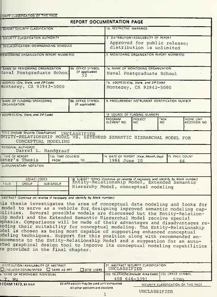
TITLE (Include Security Classification) UNCLASSIFIEDENTITY-RELATIONSHIP MODEL VS. EXTENDED SEMANTIC HIERARCHAL MODEL FOR
CONCEPTUAL MODELINGPERSONAL AUTHOR(S)
Darrel L. Handgraafi TYPE OF REPORTaster's Thesis
13b TIME COVEREDFROM TO
14 DATE OF REPORT (Year, Month, Day)
198 6 June 2
15 PAGE COUNT
MlSUPPLEMENTARY NOTATION
COSATI CODES
F'ELD GROUP SUB-GROUP
18 SUBJECT TERMS (Continue on reverse if necessary and identify by block number)Entity-Relationship Model, Extended SemanticHierarchy Model, conceptual modeling
ABSTRACT (Continue on reverse if necessary and identify by block number)
lis thesis investigates the area of conceptual data modeling and looks formodel to serve as a vehicle for, designing improved semantic modeling cap-Dilities. Several possible models are discussed but the Entity-Relation-lip model and the Extended Semantic Hierarchal Model receive specialnphasis. Comparisons will be made of their advantages and disadvantages re-arding their suitability for conceptual modeling. The Entity-RelationshipDdel is chosen as being most capable of supporting enhanced conceptualDdeling techniques. Support for this position along with recommended en-ancements to the Entity-Relationship Model and a suggestion for an auto-ated graphical design tool to improve its conceptual modeling capabilitiesre provided in the final chapter.
Distribution /availability of abstract
unclassified/unlimited d same as rpt d dtlc users
21 ABSTRACT SECURITY CLASSIFICATION
UNCLASSIFIEDa NAME OF RESPONSIBLE INDIVIDUAL
T. WU22b TELEPHONE (Include Area Code)
408 646-339122c OFFICE SYMBOL
i2J>j£g.
) FORM 1473. 84 mar 83 APR edition may be used until eihausted
All other editions are obsoleteSECURITY CLASSIFICATION OF THIS PAGE
UNCLASSIFIED
Approved for public release; distribution is unlimited.
Entity-Relationship Model vs. Extended Semantic Hierarchal ModelFor
Conceptual Modeling
by
Darrel L. HandgraafCaptain, United States Marine Corps
B. S. , Purdue University, 1979
Submitted in partial fulfillment of therequirements for the degree of
MASTER OF SCIENCE IN COMPUTER SCIENCE
from the
ABSTRACT
This thesis investigates the area of conceptual data
modeling and looks for a model to serve as a vehicle for
designing improved semantic modeling capabilities. Several
possible models are discussed but the Entity-Relationship
model and the the Extended Semantic Hierarchal Model receive
special emphasis. Comparisons will be made of their advan-
tages and disadvantages regarding their suitability for
conceptual modeling. The Entity-Relationship Model is
chosen as being most capable of supporting enchanced concep-
tual modeling techniques. Support for this position along
with recommended enhancements to the Entity-Relationship
Model and a suggestion for an automated graphical design
tool to improve its conceptual modeling capabilities are
provided in the final chapter.
TABLE OF CONTENTS
I. INTRODUCTION 6
II. WHAT IS A DATA MODEL? 9
A. GENERAL 9
1. The Primitive Data Model 9
2. The Classical Data Models 10
3. The Entity-Relationship Model ( E-RModel) . . . . 12
4. Semantic Data Models 12
5. Issues Facing Data Model Developmentand Selection 16
III. THE ENTITY-RELATIONSHIP MODEL 21
A. BRIEF DESCRIPTION 21
B. EXAMPLE OF AN APPLICATION USING THEENTITY-RELATIONSHIP MODEL 25
C. EVALUATION OF THE ENTITY-RELATIONSHIPMODEL 27
IV. THE EXTENDED SEMANTIC HIERARCHAL MODEL ( SHM+ ) . . 39
A. SEMANTIC NETWORKS 39
1. Object Schemes 39
2. Behaviour Schemes 41
B. EXAMPLE OF AN APPLICATION USING THEEXTENDED SEMANTIC HIERARCHAL MODEL 43
C. EVALUATION OF THE EXTENDED SEMANTICHIERARCHAL MODEL ( SHM+ ) 46
V. COMPARISON OF THE E-R MODEL AND SHM+ 54
VI. CONCLUSIONS AND RECOMMENDATIONS 58
VII. SUMMARY 60
LIST OF REFERENCES 62
BIBLIOGRAPHY 64
INITIAL DISTRIBUTION LIST 65
I. INTRODUCTION
Conceptual modeling refers to an abstract level of
system description which attempts to offer the database
designer a more natural way of describing and organizing a
system prior to a detailed logical or physical design
[ Ref . 9: preface]. Conceptual modeling thus is the first
step in the design process wherein the designer attempts to
present a preliminary model of all aspects of an enterprise
including the dynamic behavior of entities and
relationships, communications, man-machine interfaces,
pictures, sounds, and system environment. It is the goal of
conceptual modeling to raise the perspective of database
designers to enable them to specify more concepts,
relationships, and constraints in their application model
prior to the logical and physical design of the database.
Conceptual modeling borrows from the artificial intelligence
community on knowledge representation, and from the
programming language community on abstraction techniques.
It is the selection of a suitable model to serve as a
starting point in the development of a conceptual model that
is the focal point of the remainder of this thesis.
Recent data model research has included the search for
improvements in the interface between the data base and the
user, improvements in the tools and methodologies available
for the design and query of the database, and in reducing
the complexity of the data model itself and its
representation. Other research has looked at data
independence, semantic relativism, the integration of
structural and behavioural modeling, data and procedural
abstraction, the use of artificial intelligence, and the use
of aggregation, generalization, association, and
classification to reduce the perceptual complexity while
enhancing the conceptual modeling capabilities.
The Entity-Relationship Model has gained widespread
popularity over the past several years due largely to its
elegant simplicity and powerful semantic modeling
capabilities / particularly in modeling many-many
relationships. The question remains: Is the
Entity-Relationship Model capable of handling the increased
semantic needs of future database requirements? How does
the Entity-Relationship Model compare to other models in the
areas of understandability, design tools and methodologies,
semantic relativism, and all of the other criteria described
above?
These questions must be answered before choosing a model
to use as a basis for advanced research into conceptual data
modeling. Preliminary research indicated that the
Entity-Relationship Model would compare favorably to the
other major models. As it turned out, the final result of
this analysis and research was that the Entity-Relationship
Model with specified enhancements appears to me to display
clear and significant advantages in its ability to support
the increased semantic modeling demands of modern conceptual
modeling.
In Chapter II of this thesis, I will introduce the
concepts behind a data model, look in very broad terms at
the various major models developed to date, and look at the
various issues facing the selection of a data model to
support conceptual modeling in the future. I will then
consider the Entity-Relationship Model and the Extended
Semantic Hierarchy Model as the leading candidates to
support conceptual data modeling. In Chapter III, I will
look at the Entity-Relationship Model and its advantages and
disadvantages as a vehicle to support conceptual modeling.
Chapter IV will cover the Extended Semantic Hierarchy Model
in a similar vein. In Chapter V, I will compare the
Entity-Relationship Model and the Extended Semantic
Hierarchy Model. In Chapter VI I conclude that an extended
Entity-Relationship Model with specific enhancements and an
automated graphical design tool would be the most suitable
data model for increasing our present conceptual modeling
capabilities.
8
II. WHAT IS A. DATA MODEL ?
A. GENERAL
Brodie defined a data model as
A collection of mathematically well defined conceptsthat help one to consider and express the static anddynamic properties of data intensive applications.[Ref. 1: p. 20]
Ullman states
A data model consists of two elements. One is amathematical notation for expressing data andrelationships. The other is made up of the operationson the data that serve to express queries and othermanipulations of the data. [Ref. 2: p. 18]
From these definitions we can derive a taxonomy of data
models. One such taxonomy used by Brodie [ Ref. 1: p. 28]
,
breaks data models into four groups:
1) Primitive data models
2) Classical data models
3) Semantic data models
4) Special purpose ( application oriented) data models
In searching for a basis from which to develop an
improved data model, examples of the first three categories
above were compared and examined.
1. The Primitive Data Model
The primitive data model represents objects as
records grouped into files. Relationships are represented
by indexes and inverted lists. Possible operations are
limited to primitive read and write operations over records.
[Ref. 1: p. 28]. The primitive model's chief advantage is
that it is relatively easy to implement. This ease of
implementation costs the user the ability to model complex
or very large problems in a manner that the user can
understand. Other weaknesses of the primitive data model
will be brought out in the next section when specific issues
of data model development and selection are discussed.
2. The Classical Data Models
The classical data models include the hierarchal
data model, the network data model, and the relational data
model.
a. The Hierarchal Model
The hierarchal data model is based on the tree in which
nodes of the tree represent "objects" or "things" and the
links or edges between the nodes tie the nodes together to
form relationships. Objects are typically represented as
records that are organized in 1:N binary relationships.
[ Ref . 1: p. 29] . Typical operations on the hierarchal model
involve a navigational search, record-by-record, through the
tree from its root to the desired node or object.
The chief advantage of the hierarchal model is
its understandability and ease of use for simple
applications. Most people naturally organize data into a
hierarchy anyway, so the concepts of the hierarchal model
are common and easy to learn. More complex relationships
however, such as many-many relationships, are impossible to
directly represent with the hierarchal model without the use
of "virtual records". This inability of the hierarchal
model underscores its chief disadvantage. The virtual
records employed by .the hierarchal model have no
corresponding object in the original user application. This
introduces ambiguities and update anomalies which are very
significant. They will be considered again later when
considering the Extended Semantic Hierarchal Model.
b. The Network Model
The network model is really a superset of the
hierarchal model. A directed graph (network) replaces the
10
tree to represent objects as nodes and binary relationships
as edges or links connecting the nodes. Operations again
are characterized by navigating through the graph
record-by-record in order to select logical records for
display or update. The network model enjoys many of the
same advantages of the hierarchal model, but without the
restrictions imposed by a tree. Its chief disadvantages are
again its inability to model very complex relationships
without introducing virtual records. [ Ref . 2: pp. 25 - 32]
c. The Relational Model
The relational data model is very different from
the hierarchal and network models. The relational model is
based on the mathematical concept of the relation and uses a
n-tuple to represent both objects (a n-tuple consisting of
the object's component parts) and relationships (a n-tuple
consisting of the objects resulting from the Cartesian
product of the object tuples which are tied together by the
relationship). Relational algebra and calculus provide a
mathematical foundation for query operations and
constraints. [Ref. 2: pp. 19 - 25]. The advantages of the
relational model are many. It is mathematically complete,
so research and development of the model can go forward
knowing that they are building on a firm, provable
mathematical foundation. Relational algebra and calculus
allow implementation of the retrieval and update functions
without the necessity of using a record-by- record search of
the entire tree or network as was the case in the hierarchal
model or the network model respectively. Semantic
relativism is also supported by the relational model, in
fact, semantic relativism was first introduced by the
relational model. All entities are represented as n-ary
relations in the relational model as are relationships or
combinations of entities and relationships. The relational
model allows the dynamic definition of these n-ary relations
11
with its data manipulation languages so that a n-ary
relation can be viewed as representing an entity or a
relationship. The relational model can also directly
support many-many relationships [ Ref . 1: p. 39]. Among its
disadvantages, the pure relational model does not support
behavioural or dynamic modeling and has not benefited in its
pure form by the progress of artificial intelligence and the
use of abstraction concepts such as aggregation,
generalization, classification, and association. These
abstraction concepts are discussed in the next section on
the semantic data model. I restrict these comments to the
"pure" form of the relational model because many of the
newer semantic data models borrow techniques and concepts
from the relational model in their implementation.
3. The Entity-Relationship Model ( E-R Model )
The Entity-Relationship Model defines all components
of a database application as either entities (objects) or
relationships between those entities. This definition
process is performed statically prior to compiling the
Entity-Relationship database, thus preventing the model from
first viewing a component as an entity and then later
viewing that same component as a relationship. The
Entity-Relationship approach utilizes the
Entity-Relationship diagram ( see Languages and Methodologies
later in this chapter) to assist in the structural design of
a database application. The Entity-Relationship Model makes
no attempt to model behavioural properties but instead
relies on the Entity-Relationship diagram and the elegant
simplicity of the concepts of the model itself to quickly
enable the user to model a fairly vast array of real world
problems. This very powerful model is the subject of
further discussion in Chapter 2 of this thesis.
4. Semantic Data Models
Abstraction may be defined as the deliberate
suppression of specific details in order to present only
12
those details which are most significant and meaningful to
the user at that time. In database design the idea of data
abstraction is used to present the user with different
"views" or "levels" of the application data. This technique
would allow an upper level manager to see only very broad,
general information from a database application while still
allowing a technician or lower level manager to use the same
database with a different "view" or "level" and abstract the
detailed information they would need. Abstraction is an
important concept for conceptual modeling as it offers the
user a higher degree of understanding without a higher
degree of complexity of design or loss of detail. When one
considers the variety of data models which fall under the
heading of semantic data models, you must first define and
explore the four basic abstraction concepts supported by the
semantic data models: 1) Classification, 2) Aggregation, 3)
Generalization, and 4) Association.
a. Classification
Classification is defined by Brodie as "a simple
form of data abstraction in which an object type is defined
as a set of instances. This establishes an instance-of
relationship between an object type in a schema and its
instances in the database". In other words, we classify
atomic objects which are data items in the data base
according to what type of object they are, and then use that
type of object as an object in our schema.
An example of this might be the classification
of Mr. Rick Jones (who prepares meals at Tom's Happy Highway
Truckstop) as a cook. We would then classify all of the
employees of Tom's who work at preparing meals as a cook.
b. Aggregation
Aggregation is a type of abstraction wherein a
relationship between objects is considered to form a higher
13
level object. In other words, all or some of the attributes
of selected data items are considered to be component parts
of a higher level object. An example of this is the
aggregation of objects called cooks, waitresses, gas station
attendant, mechanics, and shift manager as the aggregate
object "shift". Another example might be the aggregation of
a gas station, garage, and restaurant as the object "Tom's
Happy Highway Truckstop". Aggregation is characterized by
the "part-of" relationship among data objects, in other
words a gas station, garage, and restaurant are all "part
of" a Tom's Truckstop. [ Ref . 6: p. 106].
c. Generalization
Generalization refers to the concept of grouping
several similar but not necessarily identical items
together. Trivial differences between the category objects
are abstracted to form a new, higher level generic object.
An example of this might be the generalization of cooks,
waitresses, shift managers, gas station attendants, and
mechanics into the object employee. Generalization refers
to the abstraction of minor differences between lower level
category objects to form a higher level generic object. The
lower level items are categories of the more general higher
level object. Generalization is characterized by the "is-a"
relationship. In other words, a cook, a waitress, a
mechanic, or a shift manager are all categories of the more
general term employee. Each type of worker "is a" category
of employee. Differences between the specific jobs are
suppressed while the generic object employee inherits common
properties of all three jobs. Thus the object employee
might have properties such as employee number, a field which
is common to cook, waitress, mechanic, etc. [Ref. 6: p.
106] .
Generalization and classification are very
similar concepts. The difference between them is that
14
classification abstracts instances of a data base into
objects of a schema, while generalization abstracts very
similar objects of a schema into new, higher level generic
objects of the schema. In our earlier example of
classification, all instances of employees who prepare meals
at Tom's were classified as cooks. We might then use
generalization to generalize all cooks and mechanics under
the generic object "skilled employees" while generalizing
gas station attendants and waitresses as "unskilled
employees". In this case we have classified the data base
instances as objects in our schema called "cooks",
"waitresses", "gas station attendants", or "mechanics" and
then generalized the gas station attendants and waitresses
as "unskilled employees" and the mechanics and cooks as
"skilled employees".
d. Association
Association is a type of abstraction wherein
identical objects are grouped into a higher level object
consisting of the set of lower level objects. An example of
this might be the grouping of all the skilled employees in
Tom's Truckstop into a trade union. There is a subtle
difference between generalization and association.
Generalization refers to the abstraction of minor
differences between lower level category objects while
association refers to the abstraction of the number of lower
level member items which have been grouped together to form
a higher level set object. Association is characterized by
the "member-of" relationship between identical items. An
example of association might be the grouping of all skilled
employees in a company into a set and calling this higher
level object a trade union. [ Ref . 1: p. 34].
Essential to the usefulness of aggregation,
generalization, and association is the concept of allowing
the higher level object to inherit attributes of the
15
component data items without having to specify which
attributes are inherited. All attributes of the component
data items are considered to be inherited by the higher
level item subject to the constraints specified by the
design of the database application. This greatly reduces
the redundancy of the data necessary to be maintained by the
database while preserving all of the desired application
semantics. This reduction in redundancy streamlines the
database for more efficient update and query operations and
greatly reduces the problems associated with data
independence in ensuring that every instance of a data item
is referenced when an update operation is invoked.
This organization of data objects into lower
level data items which are abstracted by the concepts
described above into higher level objects results in a
hierarchy of data to support multiple levels of abstraction
and thereby multiple views of the database. This natural
hierarchy is used by Smith and Smith to develop the Extended
Semantic Hierarchy Model. [ Ref . 6: pp. 105 - 133].
5. Issues Facing Data Model Development and Selection
a. Data Independence
Brodie called data independence "a principle
goal of database technology". Data independence may be
defined as the separation of data's application properties
from its implementation properties. If future data models
are to be able to represent increased application semantics
and move into the realm of conceptual data modeling, data
independence will be necessary in order to allow the
database systems which implement these models to be
manageable in size and efficiency. The primitive data model
with its files and records as its only implementation
schemes displayed very poor data independence. The
hierarchal and network models introduced the concepts of
schema and subschema to separate logical issues from
16
physical implementation issues [ Ref . 1: p. 38]. The
relational data model introduced the concept of derived
subschemas and a language which could dynamically define
views. Although implementation issues are not dealt with by
Smith and Smith in their discussion of the Extended Semantic
Hierarchy Model [ Ref s. 6,8: pp. 105 - 133, 277 - 312], I
believe that use of relational model implementation
techniques could be used to enable the Extended Semantic
Hierarchy Model to achieve the data independence and
many-many relationship modeling capability of the relational
model.
b. Semantic Relativism
Semantic relativism refers to the ability of the
user to dynamically change the way data and relationships
are viewed within an application. A prime example of the
difficulty with this view is the object "marriage". Is a
marriage a relationship between two "person" entities, or is
it an entity itself with a date, place, and license number?
If a model is to successfully move into the realm of
conceptual modeling, it should not restrict the user to one
view or another. This determination of data objects such as
marriage as either entities or relationships should be made
dynamically by the user at the time of the execution of a
query and not at the compile time of the database. The
network, hierarchal, and Entity-Relationship models do not
support semantic relativism. The relational model and most
semantic models based on the relational model, including the
Extended Semantic Hierarchy Model, do support semantic
relativism. This issue will again be discussed in those
sections covering the Entity-Relationship Model and the
Extended Semantic Hierarchy Model. [Ref. 1: p. 39]
c. Integrating Structure and Behavior
Historically, it has been the structure of
entities and their relationship that has been represented
17
and analyzed by various data models. The primitive,
network, hierarchy, relational, and the Entity-Relationship
models all were developed with the goal of modeling the
static, structural aspects of a data application. As we
attempt to enhance the semantic richness of data models, it
has become apparent that the modeling of the dynamic,
behavioural aspects of an application are equally important.
Several newer semantic models, including the Extended
Semantic Hierarchy Model and some enhanced versions of the
classical models now include behavioural modeling. This is
but one step in our goal of enhancing the conceptual
modeling of all aspects of a data base application. The
sections "Languages and Methodologies" and "Data and
Procedural Abstraction" of this chapter further explore the
concepts of structural and behavioural modeling.
d. Modeling Support
What application concepts do the data model
support? If the designer has chosen the primitive,
hierarchy, or network model he will not be able to directly
model many-to-many relationships ( see the sections "The
primitive data model" and "The classical data models" in
this chapter). If he has chosen the relational model he
will be able to support many-to-many relationships and
semantic relativism, but not behavioural modeling. If he's
chosen the Entity-Relationship Model, then he will lose
semantic relativism. If he's chosen the Extended Semantic
Hierarchy Model he will be able to support semantic
relativism and behavioural modeling, but will he be able to
directly model many-to-many relationships? Obviously the
model chosen will directly affect which application concepts
can be modeled.
e. Understandability
Understandability relates to the ease of
learning and the ease of use of a data model. It is a
18
function of the preciseness and simplicity of its
definition. The Entity-Relationship Model stands out in the
arena of understandability. To date the achievement of
understandability often times comes at the expense of
semantic richness. The Entity-Relationship Model is an
example of this. In its basic form as first published by
Chen [ Ref . 3: pp. 9 - 36]^ the Entity-Relationship model was
elegant in its simplicity. Later attempts to enhance the
Entity-Relationship Model, to add multi-level views for
example, added considerably to its complexity [Ref. 10: pp.
459 - 476] . That is where conceptual modeling comes in.
Just as higher level languages allowed the modeling and
implementation of larger and more complex applications than
was possible with lower level languages, the goal of
conceptual modeling to raise the perspective of the database
designer to a new, higher level will enable that designer to
include increased semantic specifications in his model for
yet larger and more complex applications.
f. Languages and Methodologies
The data model selected for use should provide
development methodologies and high level query languages to
design and access the application database. These languages
should be well defined and interact with the model in a
clear and precise manner. Design methodologies should
include diagrammatic techniques to assist the designer in
organizing the application. Two prevalent design tools are
the entity- relationship diagram used by the
Entity-Relationship Model, and the object and behaviour
schemes used by the Extended Semantic Hierarchal Model.
g. Interfaces
When searching for a data model to be
implemented or selecting from those models already
implemented and on the market, the interface between the
user and the data base assumes significant importance. The
19
most capable and sophisticated system in the world is
worthless if the interfaces to it are so complex or user
"unfriendly" that the user can not or will not use the
system. There are generally three types of interfaces
available. These are the natural language interface, a
query language, and a graphics interface [ Ref . 4: p. 2],
Just as modeling support and available tools will influence
the data model selection or development, the interfaces
available which have been developed or are amenable to the
data model in question should be considered.
h. Use of Artificial Intelligence Concepts
More and more often, concepts from the world of
artificial intelligence are being applied to data model
research. These concepts include semantic networks,
inheritance, higher order types, and "is-a" hierarchies.
Semantic networks can be defined simply as the
representation of application data properties by a graph in
which nodes represent objects and links between nodes
represent relationships. Obviously, the network and
hierarchal models, the Entity-Relationship Model, and the
semantic models all share common aspects of this application
modeling technique. Inheritance, higher order types, and
"is-a" hierarchies have all been previously discussed in the
section on semantic models.
Artificial intelligence's pursuit of expert
systems requires clearly defined and theoretically provable
techniques for knowledge representation. Artificial
intelligence's goal of developing a complex database of
facts, conclusions, operations, and constraints within an
expert system parallel the research for semantically rich
models in the database community. Thus, it should not seem
surprising that the two fields of study should overlap and
borrow concepts and techniques from each other. It is these
common concepts and techniques which should be considered
when developing or selecting data models for implementation.
20
III. THE ENTITY-RELATIONSHIP MODEL
A. BRIEF DESCRIPTION
What is the Entity-Relationship model? Peter Chen,
creator of the Entity-Relationship Model, provides some
basic definitions. He defined an entity as "a thing which
can be distinctly identified. " Examples of entities include
cars, persons, dates, times, etc. Entity sets are
classifications of entities. The entity set employee may be
the set classification of all "people" entities which work
for a certain company. There is a test to ascertain whether
a specific entity belongs to an entity set. If Mr. Rick
Jones works for Tom's Truckstop, we would include him in the
entity set "employee" of Tom's Truckstop. If Mr. Jones does
not work for Tom's Truckstop, then we would not include him
in the entity set "employee" of Tom's Truckstop. [ Ref . 3:
p. 10]
Peter Chen defines a relationship as "an association
among entities. " An example of a relationship might be the
"works-for" relationship between a employer and an employee.
Chen's definition of a relationship set R( i ) , "is a
mathematical relation among n entities, each taken from an
entity set: [( el, e2 , . . . , en) | el is an element of El, e2 is
an element of E2,...,en is an element of En}, and each tuple
of entities ( el, e2, . . . , en) , is a relationship. [Ref. 3: pp.
11,12]
The "role" of an entity in a relationship is a function
that it performs in the relationship. "Husband" and "wife"
are roles of the entity "person".
Specific instances of an application entity or
relationship will have properties called attributes which
are defined by the database designer. Each attribute will
be paired with a value for that attribute. Together the
21
attribute and its value will form an attribute-value pair.
An example of an attribute-value pair might be the attribute
"age" and the value "32" for the entity "employee" . An
attribute-value pair might have multiple values for a single
attribute, i. e. 555-1214 and 555-7127 . as values for the
attribute "phone number" of an entity "employee".
Relationships, as well as entities, may have attribute
value pairs. An example of a relationship with an attribute
value pair might be the attribute "num-years-employed" which
would describe the number of years an employee was with a
company in the "works-for" relationship described earlier.
Thus, an attribute is really a function which maps an
attribute-value pair to an entity or relationship.
Attributes, singly or grouped together, form an entity
key if they can form a one-to-one mapping from an entity to
a single set of attribute values. These attribute(s) thus
form an identifier for the entity. An example of an entity
key may be the attribute "SSN". Social security number
uniquely identifies members of the entity set "employee".
[Ref. 3: p. 14]
If more than one entity key exists, one of them will be
chosen as being semantically most meaningful and designated
as the entity primary key. Following the lead of Codd's
Relational Model, entities can be described by relations and
formed into entity relations. These entity relations can be
placed in tabular form with each row becoming an entity
tuple (see Table I, page 21). As Chen states, "Since a
relationship is identified by the involved entities, the
primary key of a relationship can be represented by the
primary keys of the involved entities. " . If an entity
relation can be uniquely described by the entity primary key
then that entity relation is a "regular entity relation".
An example of a regular entity relation is presented in
Table I where the entity relation "employee" is uniquely
described by the primary key "SSN". [Ref. 3: pp. 14 - 18]
22
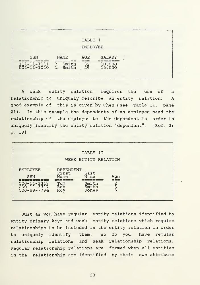
TABLE I
EMPLOYEE
SSN NAME AGE SALARY
111-11-1111001-11-1010
R. SmithL. Smith
32 10,000. 29 15,000
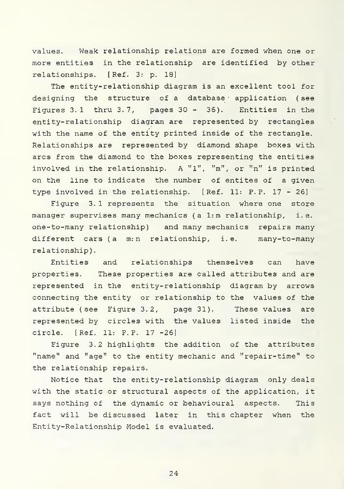
A weak entity relation requires the use of a
relationship to uniquely describe an entity relation. A
good example of this is given by Chen (see Table II, page
21). In this example. the dependents of an employee need the
relationship of the employee to the dependent in order to
uniquely identify the entity relation "dependent". [ Ref . 3:
p. 18]
TABLE II
WEAK ENTITY RELATION
EMPLOYEE
SSN
DEPENDENTFirst LastName Name Age
000-11-3317000-11-3317000-99-7794
TomBobRoy
Smith 2Smith 3Jones 5
Just as you have regular entity relations identified by
entity primary keys and weak entity relations which require
relationships to be included in the entity relation in order
to uniquely identify them, so do you have regular
relationship relations and weak relationship relations.
Regular relationship relations are formed when all entities
in the relationship are identified by their own attribute
23
values. Weak relationship relations are formed when one or
more entities in the relationship are identified by other
relationships. [ Ref . 3: p. 18]
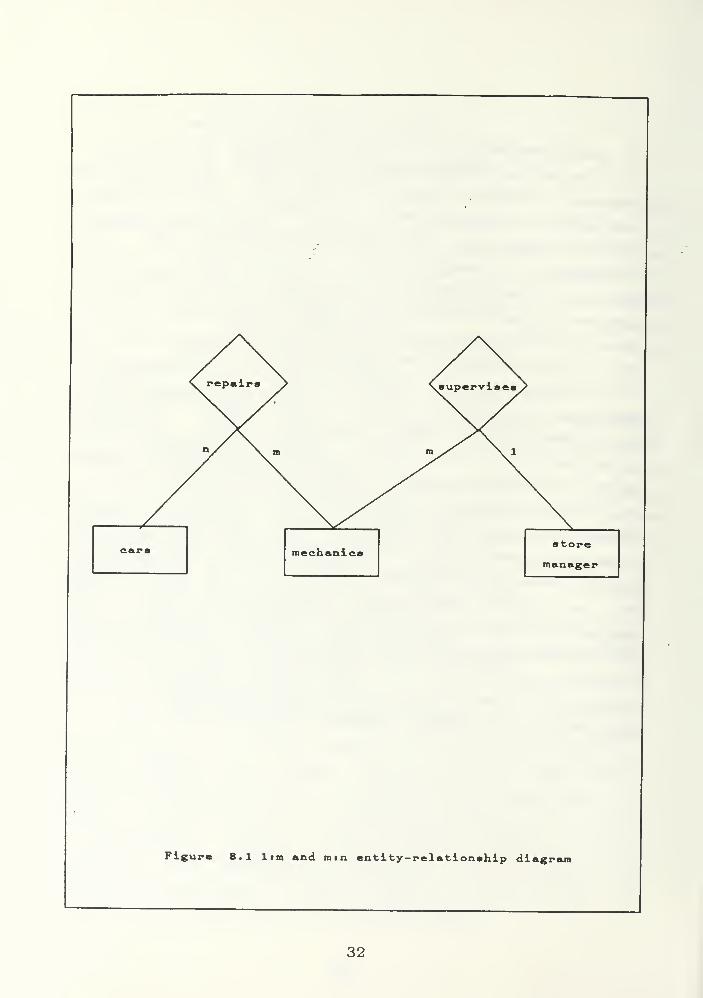
The entity- relationship diagram is an excellent tool for
designing the structure of a database application ( see
Figures 3.1 thru 3.7, pages 30 - 36). Entities in the
entity-relationship diagram are represented by rectangles
with the name of the entity printed inside of the rectangle.
Relationships are represented by diamond shape boxes with
arcs from the diamond to the boxes representing the entities
involved in the relationship. A "1", "m", or "n" is printed
on the line to indicate the number of entites of a given
type involved in the relationship. [Ref. 11: P.P. 17 - 26]
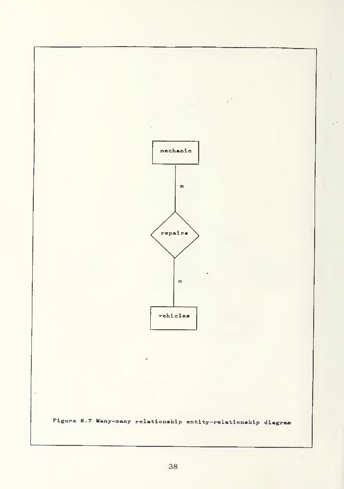
Figure 3. 1 represents the situation where one store
manager supervises many mechanics (a l:m relationship, i.e.
one-to-many relationship) and many mechanics repairs many
different cars (a m: n relationship, i. e. many-to-many
relationship)
.
Entities and relationships themselves can have
properties. These properties are called attributes and are
represented in the entity-relationship diagram by arrows
connecting the entity or relationship to the values of the
attribute (see Figure 3.2, page 31). These values are
represented by circles with the values listed inside the
circle. [Ref. 11: P.P. 17 -26]
Figure 3.2 highlights the addition of the attributes
"name" and "age" to the entity mechanic and "repair-time" to
the relationship repairs.
Notice that the entity-relationship diagram only deals
with the static or structural aspects of the application, it
says nothing of the dynamic or behavioural aspects. This
fact will be discussed later in this chapter when the
Entity-Relationship Model is evaluated.
24
B. EXAMPLE OF AN APPLICATION USING THE ENTITY-RELATIONSHIPMODEL
An example of a database application, represented here
by the Entity-Relationship Model and later again by the
Extended Semantic Hierarchy Model, would be a useful tool to
use to highlight the advantages and disadvantages of the
Entity Relationship Model. Later, when the same application
is represented using the Extended Semantic Hierarchy Model,
advantages and disadvantages of that model can be made along
with comparisons of the Entity-Relationship Model and the
Extended Semantic Hierarchy Model.
The example application requires the modeling of Tom's
Happy Highway Truckstops. Each truckstop consists of a gas
station with gas station attendants, an auto/truck repair
garage with certified mechanics, and a restaurant with cooks
and waitresses. The truckstop is open twenty four hours a
day and is manned by three shifts of employees with a shift
manager for each shift and a store manager for each
truckstop in the chain. The cooks and mechanics are
considered to be skilled employees, the gas station
attendants and waitresses are considered to be unskilled
employees, and the shift managers and store managers are
considered to be management employees. The income of Tom's
Happy Highway Truckstops is limited to food receipts,
gasoline receipts, and repair receipts. The only expenses
considered will be wages, supply costs, and general
operating costs. The profit/loss is simply the specified
income minus the expenses. An entity-relationship diagram
is used to represent the Entity-Relationship Model's
approach to the problem.
Peter Chen describes his prefered technique for logical
database design using the Entity-Relationship Model:
1) Identify entity types
2) Identify relationship types
3) Draw an entity-relationship diagram with entity andrelationship types
25
4) Identify value types and attributes
5) Translate the entity- relationship diagram into a datastructure diagram
6) Design record formats
1. Identify entity types
For this example we will choose the following to be
entity types:
a cooks, gas station attendants, waitresses, mechanicsshift managers, store managers
b unskilled employees, skilled employees, managementemployees
c gas receipts, food receipts, repair receipts
d wages, supply costs, general expenses
e profit/loss, income, expenses
f gas station, restaurant, garage, vehicles
2. Identify relationship types
For this example we will choose the following to be
relationships:
a SUPERVISES; shift managers supervise skilled andunskilled employees
b UNSKILLED MEMBER; waitresses and gas station attendantsare unskilled
c SKILLED MEMBER; cooks and mechanics are skilledemployees
d INCOME GENERATION: income is generated from gas, food,and repair receipts
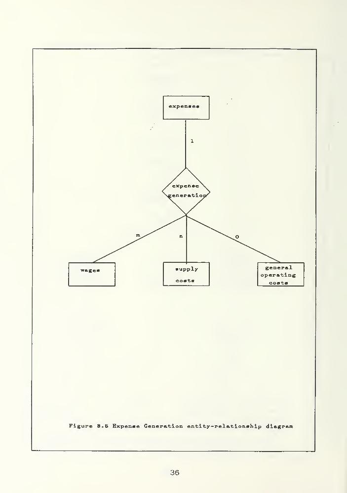
e EXPENSE GENERATION; expenses are generated from wages,supply costs, and general operating costs
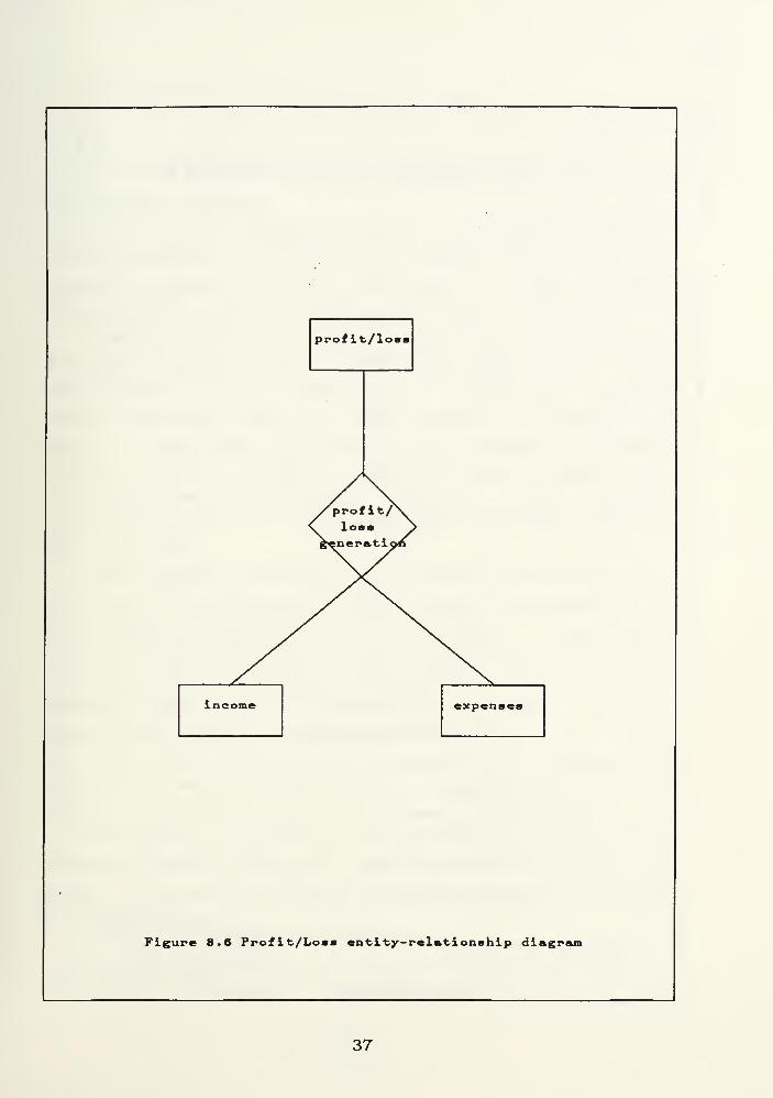
f PROFIT/LOSS GENERATION; profit or loss result fromincome vs. expenses
g REPAIRS; mechanics repair vehicles
3. Draw entity relationship diagram
Figures 3.3 to 3.7 illustrate but one possible
representation of our example application.
4. Identify value types and attributes
Some attributes which might be included in our example
would be age, name, SSN, salary, and skills for the entity
"mechanic".
5,6. Steps five and six
26
Steps five and six from Chen's logical database design
methodology are implementation dependent and will not be
discussed here when comparing data models and their
suitability for conceptual modeling.
C. EVALUATION OF THE ENTITY-RELATIONSHIP MODEL
The issues facing data model selection/development
described in Chapter I of this thesis will serve as a basis
for evaluating the Entity-Relationship Model and its
suitability for conceptual modeling.
a. Data Independence
The Entity-Relationship Model supports the
concepts of schema and subschema for logical data
independence. In our example application Tom' s Truckstop
staff was broken down into management, skilled, and
unskilled employees. The skilled and unskilled employees
were further broken down into cooks, mechanics, waitresses,
and gas station attendants. Derived schemas and the ability
to dynamically change schemas and subschemas is not
supported by the Entity-Relationship Model. This static
nature of the Entity-Relationship Model limits its
suitability for conceptual modeling with its need of
supporting multiple views.
b. Semantic Relativism
The Entity-Relationship Model does not support
semantic relativism. Steps one and two of Chen's design
methodology dictate the classification of all application
objects as either entities or relationships. Once this
determination has been made, it can not be changed without
restructuring and recompiling the database. If we wanted to
expand our example application to include data on individual
employees who are married to other employees, we would have
to classify "marriage" at compile time as either an entity
or a relationship. If we declared marriage to be a
relationship, the manager or other user could find out which
27
employee is related to which other employee by marriage, but
it would not allow another user to view marriage as an
attribute of the entity "employee" or still another user to
view marriage as an entity. Again the static nature of the
Entity-Relationship Model limits its • suitability for
conceptual modeling.
c. Integration of Structure and Behaviour
The Entity-Relationship Model includes no
features for the modeling of behaviour or its integration
with structural concepts into one logical design.
Transactions to add, delete, or update employee records are
not specified in the Entity-Relationship Model or the
entity- relationship diagram. This is unfortunate because
it encourages the view of the application's structure as
being completely separate and independent of the
application' s behaviour, when in truth the final system
design is more realistic and less likely to contain
conceptual errors if the behaviour and structure are
designed together. This obviously is a major drawback to
the adoption of the Entity-Relationship Model for conceptual
modeling.
d. Modeling Support
The Entity-Relationship Model directly supports
the modeling of many-many relationships. In the example
application, many mechanics are assigned to repair many
vehicles. This is an advantage over most semantic models
including the Extended Semantic Hierarchal Model. These
models can not directly model many-many relationships but
instead rely on the user to break the many-many relationship
into two relationships: a many-one relationship and a one-
many relationship. The Entity-Relationship Model also
directly supports one-many (i.e. one shift manager to many
skilled and unskilled employees). Property inheritance
through generalization, association, or aggregation is not
28
supported by the basic Entity-Relationship Model. Another
strong point in favor of the Entity-Relationship Model is
its breakdown of the real world into relationships and
entities instead of just objects as do the object oriented
models like the Extended Semantic Hierarchal Model. In the
example of Tom's Happy Highway Truckstop we modeled the
"supervises" relationship .between the shift manager and the
skilled and unskilled employees. "Supervises" is a verb not
a noun, and as such it is awkward to model this relationship
as an object. This advantage of the Entity-Relationship
Model will be discussed further in Chapter III, but for now
let it suffice to say that the use of relationships in
modeling is an advantage of the Entity-Relationship Model
for conceptual modeling. Thus, the Entity-Relationship
Model's direct support of many-many relationships would give
it an advantage in conceptual modeling over other models
without such a capability. The Entity-Relationship Model's
lack of concepts such as aggregation, generalization, and
association prevent the use of the important concept of
property inheritance and thus greatly increase the amount of
data which must be included in the database when modeling
complex applications. The Entity-Relationship Model, like
other models, therefore gets mixed grades in the area of
modeling support for conceptual modeling,
e. Understandability
The Entity-Relationship Model is easy to learn
and does an outstanding job of conveying the semantics of
structural relationships to the user. The structure of the
example application is easy to see with the aid of an
entity-relationship diagram. The Entity-Relationship
Model's simple, elegant set of concepts naturally and
concisely convey the application' s structure to the user.
It therefore gets high marks for understandability for
structural modeling.
29
f. Languages and Methodologies
The entity-relationship diagram as covered in
this chapter is one of the best tools yet devised for
presenting the structural semantics .of a database
application in a clear, concise, and easy to understand
manner. The object and behaviour diagrams of Chapter IV are
also fairly simple, clear, and concise and represent not
only the structural semantics of an application, but also
the gross behavioural semantics as well. The object and
behaviour diagrams' use of aggregation, generalization, and
association render them unsuitable for direct use by the
Entity-Relationship Model, however I see no reason that
behavioural aspects could not be superimposed over the
entity-relationship diagram to yield a similar effect to
that of the behaviour diagrams.
Chen's methodology described earlier in this
chapter for implementing database applications is an
excellent technique. It nicely bridges the gap between
logical design and implementation. Algebras have also been
developed for the Entity-Relationship Model [ Ref s. 12,13]
along with normalization techniques [ Ref. 14] . The
Entity-Relationship Model therefore already has in place a
fairly rich library of languages and methodologies to use in
support of conceptual modeling.
g. Data and Procedural Abstraction
The Entity-Relationship Model is not based on
nor influenced by recent advances in programming language
theory. Therefore, although the Entity-Relationship Model
does utilize the concepts of localization and modularity of
design, it does not utilize abstraction techniques for data
or procedures. Because of the immense amounts of data
necessary for conceptual modeling, the absence of
abstraction techniques severely limits the suitability of
the Entity-Relationship Model for conceptual modeling.
30
h. Interfaces
As previously discussed in Chapter II, the use
of graphics interfaces will become more and more prevalent
as conceptual models attempt to convey more and more
information to the user. The Entity-Relationship Model with
its elegance of design and the simplicity of the
entity-relationship diagram is very suitable for graphical
interfaces. This would be an importent consideration in the
implementation of any future conceptual models.
i. Use of Artificial Intelligence Concepts
The use of concepts from the artificial
intelligence community would be difficult to integrate with
those concepts of the Entity-Relationship Model. Concepts
such as abstraction, inheritance, dynamic constraints, and
multiple views are not part of the Entity-Relationship Model
and would have to overlay the structural concepts which it
embraces. This would be awkward at best and eventually lead
to the development of a two step methodology to bring both
separate techniques together. This is not as conceptually
clear as a model which could integrate both views. As
regards the use of artificial intelligence concepts, the
Entity-Relationship Model can be adopted to include such
concepts as abstraction and multiple views, but it is not as
conceptually clean as a model which integrates these
concepts into its overall strategy right from the start.
31
mechanicsstore
manager
Figure 8.1 lim and mm entity-relationship diagram
32
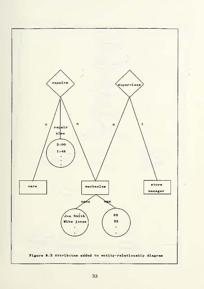
Figure 8.3 Attributes added to enti ty-rel atlonshlp diagri
33
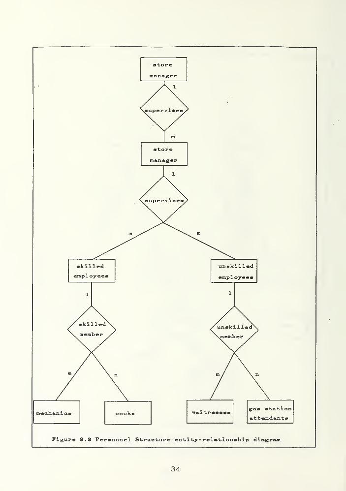
killedemployee!
techanicf waltrene* gas station
attendants
Figure 8.8 Personnel Structure entity-relationship diagram
34
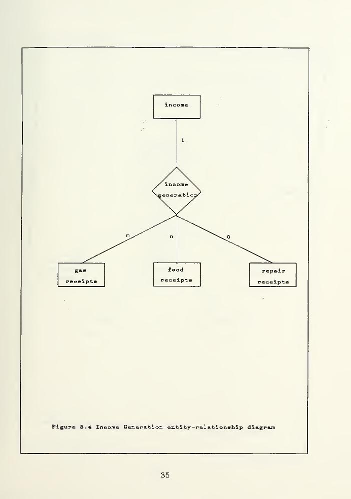
Figure 8.4 Income Generation entity-relationship diagram
35
expenses
wages
Figure 8.5 Expense Generation entity-relationship diagram
36
prof i t/loss
incom< expenses
Figure 8.6 Profit/Loss entity-relationship diagram
37
mechanic
vehicles
Figure 8.7 Many-many relationship entity-relationship diagram
38
IV. THE EXTENDED SEMANTIC HIERARCHAL MODEL ( SHM+ )
A. SEMANTIC NETWORKS
Just what is a semantic network? A semantic network is
a representation of a real world problem wherein nodes of a
network represent objects and edges or links represent
binary associations between objects. [ Ref . 9: Preface]
Semantic network models find their roots in the field of
knowledge representation in Artificial Intelligence. Israel
and Brachman maintain that semantic networks and the data
models embracing them as their logical cornerstone were
derived from Quillian's work in the 1960s on Semantic
Memory. They go on to say that Wood's paper "What's in a
Link" published in 1975 gave credence to formally defined
semantic networks as a "representation language". [Ref. 9:
pp. 119 - 147]
These semantic networks are organized along abstraction
concepts of classification, generalization, association, and
aggregation (see Chapter II of this thesis). The Extended
Semantic Hierarchal Model is an example of a data model
based on semantic networks. Like other semantic network
models, SHM+ uses the abstraction concept to form a
hierarchal network. Again, as described earlier in Chapter
II, this hierarchy of objects together with the abstraction
concepts allow the model to employ property inheritance to
reduce the redundancy of the data base specifications.
Structural and behavioural properties are modeled in the
Extended Semantic Hierarchy Model advocated by Smith and
Smith. This model uses object schemes and behavior schemes
as design tools.
1. Object Schemes
The application is first modularized into a
hierarchy of objects. These objects are represented by
39
object schemes. The object scheme is a directed graph in
which nodes represent objects and the links identify
aggregation, generalization, and association used to relate
objects to each other. [ Ref . 7: p. 284]
Aggregation utilizes upward inheritance so that
properties of the components are inherited by the upper
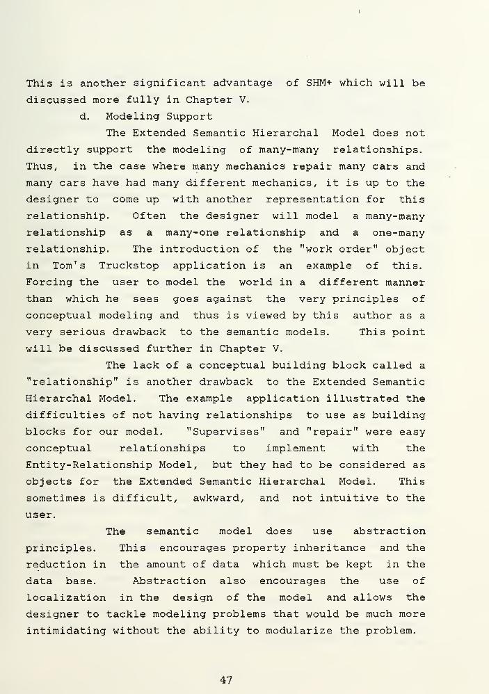
level object. In the object scheme of Figure 4. 1, the upper
level object Profit/Loss inherits the properties of the
component objects income and expenses. Units of measure
(dollars) is one possible property that the aggregate object
could inherit from the component parts. In the diagram,
aggregation is represented by the single arrow with
horizontal and vertical lines which connect Expenses, Income
and Profit/Loss. This is different from the double headed
vertical arrow representing association in Figure 4. 2 or the
two slanted arrows representing generalization used in
Figure 4. 3.
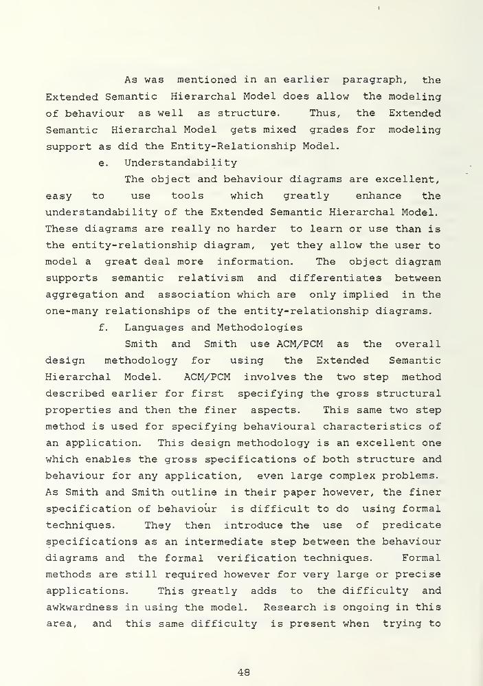
Like aggregation, association supports upward
inheritance. Upper level objects inherit the properties of
the lower level members. In the object scheme of Figure
4.2, the object trade union inherits the properties of the
member objects mechanics. In this case the trade union
might inherit the property "skills" of its member objects so
that the skills represented in the trade union could be
inherited by the mechanics which make up the union. Again,
note the vertical, double headed arrow used to represent
association.
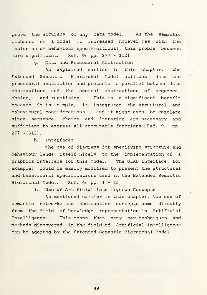
Unlike aggregation and association, generalization
supports downward inheritance so that the lower level
category objects inherit the properties of the upper level
generic object. In the object scheme of Figure 4.3 the
mechanics and cooks objects inherit the properties of the
generic object skilled employee. As noted earlier, slanted,
single headed arrows are used to represent generalization.
40
Aggregation, association, and generalization
techniques are used to create new objects from component or
member objects. These same concepts are used to decompose
high level objects into lower level objects. [ Ref . 7: p.
285]
2. Behaviour Schemes
While object schemes are used to specify structural
properties of the Extended Semantic Hierarchy Model,
behaviour schemes are used to specify its dynamic properties
(see Figure 4.4). Smith and Smith define a behaviour scheme
as "an explicit graphical representation of a single action
or transaction." [Ref. 7: p. 289]. "Transactions" check to
ensure necessary preconditions are met, invoke precisely
defined operations on objects, and then check necessary
post-conditions. This is all done so that a user might call
a simple transaction like "hire-mechanic" and be assured
that the transaction will make all necessary arrangements to
ensure data integrity. "Actions" are the same as
transactions except that actions invoke operations on single
objects. A hierarchy exists wherein transactions on sets of
objects invoke actions on each member object to perform the
required database altering operations. The behaviour scheme
itself is simply an object scheme with each object affected
by the transaction included plus an operation label on each
edge, one for each operation. The operations supported by
Smith and Smith's behaviour scheme are: INSERT an object,
DELETE an object, UPDATE an object, FIND an object in the
database, CREATE an object, and REQUEST an object from the
user. A double arrow points from the gross transaction
being modeled towards the highest level object that the
transaction operates on, and a single arrow labeled with the
constituent actions of the gross transaction points from the
object invoking the action towards the object invoked by
that constituent action. The example of Figure 4. 4 shows
41
how the "hire-mechanic" action invokes operations on the
object "skilled employees".
By utilizing modularization techniques, a fairly
complex gross transaction can be broken down into its
constituent actions and modeled with the behaviour scheme.
As defined earlier, abstraction is the deliberate
suppression of specific details in order to enhance the
clarity and understanding of more important details which
are presented to the user. Data abstraction refers to the
static, structural properties of data and its relationships.
Procedural abstraction refers to the abstraction of details
concerning the dynamic properties of data to include
operations and constraints which can be applied to the data.
Early data models including the primitive,
hierarchal, network, relational, and Entity-Relationship
models were only concerned with data abstraction. Later
semantic models, and revisions or updates of some of the
classical models now incorporate procedural abstraction
techniques. The Extended Semantic Hierarchy Model further
builds on data abstraction concepts by providing procedural
abstraction such that a parallel is drawn between data
abstractions and control abstractions. Smith and Smith
refer to the three forms of control abstractions ( sequence,
choice, and repetition) as behavioural analogs to the three
forms of data abstraction ( aggregation, generalization, and
association respectively). Aggregation corresponds to
either sequence or parallel relationship of operations. An
operation on an aggregate object is composed of either a
sequence or parallel of operations, one on each component.
An example of this would be a delete transaction on the
aggregate object mechanic. This gross transaction would be
executed by sequential or parallel deletion actions on
employee name, employee number, SSN, salary, and skills.
Generalization corresponds to choice because an operation on
42
a generic object is composed of a choice of operations, one
for each category object. An example of this would be the
deletion transaction applied to the generic object skilled
employee which would be executed by the choice of deleting
an instance of either the mechanic object or the cook object
(see Figure 4.3). Association corresponds to the repetition
of actions. An example of this would be the deletion
transaction of the entire trade union which would be
executed by repetitively deleting all of the member
mechanics (see Figure 4.2).
B. EXAMPLE OF AN APPLICATION USING THE EXTENDED SEMANTICHIERARCHAL MODEL
Smith and Smith advocate the use Active and Passive
Component Modeling (ACM/PCM) which involves a two step
process for the structural design of an application data
base. "First, the gross structural properties (e.g.,
objects and their relationships) are designed. Second, the
fine details of those properties are specified. Object
schemes are used for the gross structure design, and a
structure specification language, Beta, is used for
structure specification." [ Ref . 9: pp. 277 - 312]
ACM/PCM uses a similar two step method for modeling the
behavioural aspects of a database application. The gross
behavioural properties are first designed by specifying the
actions and transactions to be used and the objects they
will affect. This first step is done with the use of
behaviour diagrams. The fine details of the gross actions
and transactions are then specified through the use of
predicate behaviour specifications. Smith and Smith warn
however, that while the use of predicate behaviour
specifications are "adequate for most database
applications. .. particularly complex applications, with many
objects, relationships, and constraints, require the
precision and analysis that advanced formal approaches have
43
so far been able to provide". These advanced formal
approaches generally require a high degree of mathematical
sophistication which then make them difficult and awkward to
use. [Ref. 9: pp. 277 - 312]
We will use object and behaviour diagrams to model Tom's
Happy Highway Truckstop and then in the next chapter we can
compare the design of the application with these tools as
opposed to the use of the entity-relationship diagrams used
with the Entity-Relationship Model in chapter III.
We start off our modeling procedure by identifying and
classifying the objects to be present in our model. For our
example we will identify the following objects and data
items:
a employee name. age. social security number (SSN),salary, and skills they may possess which are used intheir job.
b cooks, gas station attendants, waitresses, mechanics,shift managers, store managers
c date, items, amount, tax, and total (all fields forfood receipts)
d date, no. gallons, type gas, total (all fields for gasreceipts)
e date, parts, labor, vehicle, total (all fields forrepair receipts)
f wages, supply costs, general expenses
g profit/loss, income, expenses
h gas station, restaurant, garage, vehicles
i work orders( for vehicle repair).shift-mgr-supervised-emp( employees supervised by shiftmanager)
Unlike the Entity-Relationship Model, there are no
"things" called relationships in the Extended Semantic
Hierarchal Model, only objects. Therefore we start our
modeling procedure by defining the instances of data items
in our data base and then classifying them into the objects
we will use in our model. We then use the abstraction
concepts of aggregation, generalization, and association to
build higher level objects.
44
The mechanic objects will be formed by the aggregation
of the fields name, age, SSN, salary, and skills. The other
types of employee objects will be similarly formed with the
exception that the unskilled positions will not require the
"skills" field. Figure 4.5 illustrates the aggregation of
the mechanic object.
Figure 4. 6 illustrates the use of generalization to form
the skilled and unskilled employee objects. Figure 4. 7
demonstrates the use of aggregation to form the food
receipts object. Gasoline and repair receipts will be
similarly formed. Income and expense objects are formed by
generalization as shown in Figure 4. 8, and the Profit/Loss
object is the aggregate of the income and expense objects
(see Figure 4.9). The gas station, restaurant, and garage
are all formed by aggregation in a similar fashion to that
of Figure 4. 10.
Because the object diagrams do not include the use of
explicit items called relationships, action-verb forms of
relationships like "supervise" and "repair" must be modeled
with objects. This causes the designer to convert verbs
like "supervise" and "repair" to nouns or objects. In the
case of Tom's Happy Highway Truckstops, one possibility is
to use a generalized object called
"shift-mgr-supervised-emp" for the "supervise" relationship
between the shift manager and the employees ( see Figure
4.11). The "repair" relationship of the entity- relationship
diagram is replaced with the introduction of an aggregate
object called a work order, used here to relate the mechanic
to the vehicles he repairs, (see Figure 4.12)
The object diagrams of figures 4.5 to 4.12 complete the
first step of Smith and Smith's design methodology by
completing the gross structural design. This step has
yielded a result very similar to that of the
entity-relationship diagrams used for Tom's Truckstop
example in Chapter III.
45
The Extended Semantic Hierarchal Model and the behaviour
diagrams allow us to go beyond mere structural
considerations however and allow the user to model the
behaviour of his application as well as its structure.
Figure 4. 4 illustrates the use of the behaviour diagram to
specify the gross design of the hiring of a new mechanic at
Tom's. The "hire-mechanic" transaction allows the user to
add a mechanic to the database. Similar transactions could
be specified with the behaviour diagram to add , delete, or
update the records of other employees, sales, or any other
modifications to the data base desired by the user.
C. EVALUATION OF THE EXTENDED SEMANTIC HIERARCHAL MODEL( SHM+)
a. Data Independence
Data independence is supported by SHM+ through
its use of schemas and subschemas. It also makes advances
in logical data independence by encouraging a hierarchy of
behaviour transactions and actions.
b. Semantic Relativism
The Extended Semantic Hierarchal Model supports
semantic relativism. This is one of the most important
advantages of object-oriented models. Because SHM+ does not
differentiate between objects and relationships, all objects
can be viewed as either objects or relationships as the user
desires. The significance of this will be discussed more
fully in Chapter V.
c. Integration of Structure and Behaviour
SHM+ encourages the integration of structural
and behavioural design through the use of object and
behaviour diagrams. The two steps for structural design are
done iteratively with the two steps of the behavioural
design. This allows the designer to truly integrate both
aspects of the design and to ensure that they complement
each other and accurately model the required application.
46
This is another significant advantage of SHM+ which will be
discussed more fully in Chapter V.
d. Modeling Support
The Extended Semantic Hierarchal Model does not
directly support the modeling of many-many relationships.
Thus, in the case where many mechanics repair many cars and
many cars have had many different mechanics, it is up to the
designer to come up with another representation for this
relationship. Often the designer will model a many-many
relationship as a many-one relationship and a one-many
relationship. The introduction of the "work order" object
in Tom's Truckstop application is an example of this.
Forcing the user to model the world in a different manner
than which he sees goes against the very principles of
conceptual modeling and thus is viewed by this author as a
very serious drawback to the semantic models. This point
will be discussed further in Chapter V.
The lack of a conceptual building block called a
"relationship" is another drawback to the Extended Semantic
Hierarchal Model. The example application illustrated the
difficulties of not having relationships to use as building
blocks for our model. "Supervises" and "repair" were easy
conceptual relationships to implement with the
Entity-Relationship Model, but they had to be considered as
objects for the Extended Semantic Hierarchal Model. This
sometimes is difficult, awkward, and not intuitive to the
user.
The semantic model does use abstraction
principles. This encourages property inheritance and the
reduction in the amount of data which must be kept in the
data base. Abstraction also encourages the use of
localization in the design of the model and allows the
designer to tackle modeling problems that would be much more
intimidating without the ability to modularize the problem.
47
As was mentioned in an earlier paragraph, the
Extended Semantic Hierarchal Model does allow the modeling
of behaviour as well as structure. Thus, the Extended
Semantic Hierarchal Model gets mixed grades for modeling
support as did the Entity-Relationship Model.
e. Understandability
The object and behaviour diagrams are excellent,
easy to use tools which greatly enhance the
understandability of the Extended Semantic Hierarchal Model.
These diagrams are really no harder to learn or use than is
the entity-relationship diagram, yet they allow the user to
model a great deal more information. The object diagram
supports semantic relativism and differentiates between
aggregation and association which are only implied in the
one-many relationships of the entity-relationship diagrams.
f. Languages and Methodologies
Smith and Smith use ACM/PCM as the overall
design methodology for using the Extended Semantic
Hierarchal Model. ACM/PCM involves the two step method
described earlier for first specifying the gross structural
properties and then the finer aspects. This same two step
method is used for specifying behavioural characteristics of
an application. This design methodology is an excellent one
which enables the gross specifications of both structure and
behaviour for any application, even large complex problems.
As Smith and Smith outline in their paper however, the finer
specification of behaviour is difficult to do using formal
techniques. They then introduce the use of predicate
specifications as an intermediate step between the behaviour
diagrams and the formal verification techniques. Formal
methods are still required however for very large or precise
applications. This greatly adds to the difficulty and
awkwardness in using the model. Research is ongoing in this
area, and this same difficulty is present when trying to
48
prove the accuracy of any data model. As the semantic
richness of a model is increased however ( as with the
inclusion of behaviour specifications), this problem becomes
more significant. [ Ref . 9: pp. 277 - 312]
g. Data and Procedural Abstraction
As explained earlier in this chapter, the
Extended Semantic Hierarchal Model utilizes data and
procedural abstraction and presents a parallel between data
abstractions and the control abstractions of sequence,
choice, and repetition. This is a significant benefit
because it is simple, it integrates the structural and
behavioural considerations, and it might even be complete
since sequence, choice and iteration are necessary and
sufficient to express all computable functions [ Ref. 9: pp.
277 - 312] .
h. Interfaces
The use of diagrams for specifying structure and
behaviour lends itself nicely to the implementation of a
graphics interface for this model. The GLAD interface, for
example, could be easily modified to present the structural
and behavioural specifications used in the Extended Semantic
Hierarchal Model. [Ref. 4: pp. 1 - 25]
i. Use of Artificial Intelligence Concepts
As mentioned earlier in this chapter, the use of
semantic networks and abstraction concepts come directly
from the field of knowledge representation in Artificial
Intelligence. This means that many new techniques and
methods discovered in the field of Artificial Intelligence
can be adopted by the Extended Semantic Hierarchal Model.
49
Profit/Los*
Income Expenses
Figure 4.1 Object scheme representing aggregation
Trade
Union
Mechanics
Figure 4.2 Object scheme representing association
Skilled
Employees
Mechanics Cooks
Figure 4.8 Object scheme representing generalisation
50
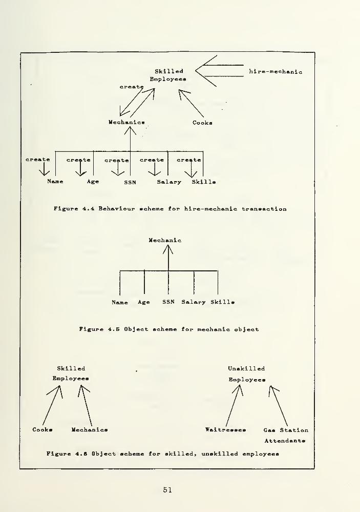
SkilledEmployees
hi re-mechanic
creat'-71
Mechanics Cooki
create
Icreate create
r ":t
create create
Age SSN Salary Skills
Figure 4.4 Behaviour scheme for hire-mechanic transact!
Mechanic
A
Name Age SSN Salary Skills
Figure 4.5 Object scheme for mechanic object
Skilled
Employees
Unskilled
Employees
Cooks Hechanli Waitresses Gas Station
Attendants
Figure 4.6 Object scheme for skilled, unskilled employees
51
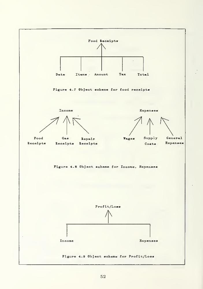
Food Receipts
Date Items Amount Tax Total
Figure 4.7 Object scheme for food receipts
Food
Receipts
Income
A
Gas
Receipti
Expenses
RepairReceipt*
Wages
/K
Supply
Costs
GeneralExpenses
Figure 4.8 Object scheme for Income, Expenses
Profit/Loss
Income Expenses
Figure 4.0 Object scheme for Profit/Losi
52
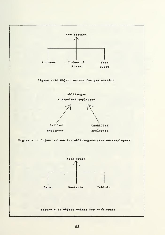
Gas Station
Address Number of
PumpsYear
Built
Figure 4 . 10 Object scheme for gas station
shift-mgr-
supervised-employees
Skilled
Employees
Unskilled
Employees
Figure 4.11 Object scheme for shif t-mgr-supervised-employ<
Work order
/K
Date Mechanic Vehicle
Figure 4.12 Object scheme for work order
53
V. COMPARISON OF. THE E^B MODEL AND SHM+
After analyzing the Entity-Relationship Model and the
Extended Semantic Hierarchal Model individually, the
strengths and weaknesses of each model must be compared to
determine which model, if either, is best suited for
conceptual modeling.
The principle strengths of the Entity-Relationship Model
over the Extended Semantic Hierarchal Model are :
1) It readily supports many-many relationships (seeChapter III, section G. ). The Extended SemanticHierarchal Model forces the user to change the way hethinks about relationships and instead break many-manyrelationships into a pair of one-many and many-onerelationships. This goes against the chief principleof conceptual modeling which stresses an easy andnatural method of modeling enterprises. The exampleof Tom s Truckstop in Chapter IV with many mechanicswho "repaired many vehicles illustrates this problemand highlights the advantage of theEntity-Relationship Model in this area. Anotherexample would be the modeling of many students whoattend classes in many rooms. " This would be directand very simple to model with the Entity-RelationshipModel, but it would be far more difficult to directlyrepresent with an object-oriented model like SHM+.
2) The Extended Semantic Hierarchal Model only supportsthe concept of objects, whereas theEntity-Relationship Model supports the concepts ofentities (objects) and relationships. This breakdownaids the communication of ideas as it parallels thatof the spoken or written language which breaks downsimple sentences into subjects and predicates(entities and relationships) or subject, predicate,and object (entity, relationship. and entity). Asseen in the example of Tom s Truckstop, the inclusionof relationships allows for a more natural and easymodeling of concepts such as supervises orrepairs". One possibility is to use the same actions
as Smith and Smith s behaviour diagram: INSERT anobject, DELETE an object, CREATE an object, UPDATE anobject, FIND an object in the database, and REQUEST anobject from the user. The example used earlier with abehaviour diagram to hire a mechanic (Figure 4.4),could be done with an expanded E-R diagram in a mannersimilar to that depicted in Figure 5. 1. Again, as isthe case with the behaviour diagram, pre-conditionsand post-conditions would be checked automaticallybefore the transaction would be executed.
3) The Entity-Relationship Model is easier to learn anduse because of those advantages outlined in numbers 1and 2 above.
4) The Entity-Relationship Model has a well defined, stepby step procedure to guide the user from conceptual
54
design through logical and physical design toimplementation. This clearly defined procedureensures that the user s original view of theenterprise is preserved throughout the design processand aids conceptual modeling.
5) The Entity-Relationship Model was originally publishedin 1976 and has benefited more from additionalresearch than has the Extended Semantic HierarchalModel based on Smith and Smith s 1977 paper [ Ref . 6:
?p. 105 - 133]. Data manipulation languages, queryanguages, normalization techniques, and algebras have
all been developed for the Entity-Relationship Modelalong with several data base management systems basedon the Entity-Relationship Model. Enhancements to theEntity-Relationship Model have been proposed toinclude the inclusion of multiple views andabstraction [ Ref s. 10,15], the inclusion of the timefactor to data modeling [ Ref. 161 , and in modelingbehaviour through action modeling [Ref. 17].
The principle strengths of the Extended Semantic
Hierarchal Model are:
1) It supports semantic relativism while theEntity-Relationship Model does not. As stated earlierin Chapter II, semantic relativism allows differentviews of the same data to coexist. This increases theflexibility of the model and decreases the updateanomalies which may occur.
2) The Extended Semantic Hierarchal Model integrates thedesign of structure and behaviour. This is anadvantage for the Extended Semantic Hierarchal Model,however I feel the Entity-Relationship Model could beeasily modified to include at least the grossbehaviour specifications through techniques similar tothose used by the Extended Semantic Hierarchal Model.The behaviour diagrams of SHM+ overlay transactionsonto the object diagrams with a clearly defined set ofpossible actions. Specification of transactions tooverlay the entity-relationship diagram could likewisebe accomplished with a definitive set of possibleactions to be invoked. In my opinion then. thisadvantage of the Extended Semantic Hierarchal Modelcould be reduced or eliminated if future research wereto be focused on it.
3) The Extended Semantic Hierarchal Model not onlyincludes methods for data abstraction, but also forprocedural abstraction as well. As stated in thePrevious paragraph, it is my belief that thentity-Relationship Model could be enhanced to include
behavioural modeling along with its present structuralmodeling. At the present time however, the ExtendedSemantic Hierarchal Model clearly enjoys the advantagein its integration of structural and behaviouraldesign concepts.
4) Again because of the Extended Semantic HierarchalModel's inclusion of behaviour specifications, its useof object and behaviour diagrams can relate moreinformation than the entity- relationship diagram whichonly deals with the structural aspects of anapplication.
5) The Extended Semantic Hierarchal Model uses multipleviews and abstraction techniques. As stated earlier,
55
research has advanced the Entity-Relationship Model sothat the important considerations of multiple viewsand abstraction techniques can be applied to theEntity-Relationship Model as well. This then can notrealistically be considered an advantage of SHM+today.
56
•killedemployed
create
t
mechanics
create cruate create
?
i»Ce
S 5N
tkill
sal lry
hire-mechanic
create
I
Figure 5.1 E-R diagram with behaviour for hire-mechanic transaction
57
VI. CONCLUSIONS AND RECOMMENDATIONS
As stated in the introduction, I have looked at various
data models in order to select one I believe is most
suitable for expansion and enhancement to accomplish a
higher degree of conceptual modeling than is possible today.
After some preliminary study, I chose to focus on the
Entity-Relationship Model and the Extended Semantic
Hierarchal Model. Chapter V compared the two models and
highlighted their strengths and weaknesses. Neither model
is perfect nor presently capable of supporting any
significant degree of conceptual modeling, but it is my
opinion that the Entity-Relationship model offers the most
possibilities. The basic Entity-Relationship Model can be
modified to include abstraction techniques, multiple views,
and behaviour. An enhanced Entity-Relationship Model
incorporating such changes still would not support semantic
relativism as does the Extended Semantic Hierarchal Model,
but it would be possible to directly model many-many
relationships and common action oriented relationships such
as "supervises" or "repairs" found in the example which the
Extended Semantic Hierarchal Model and other object oriented
semantic models cannot represent. In weighing the pro's and
con's of each model, I think that the ability to easily and
naturally model an enterprise is much more crucial to
conceptual modeling than is the issue of semantic
relativism. SHM+ and other object oriented network models
force the user to view an enterprise in an unnatural manner.
This view leads to errors in communication and specification
of an enterprise's basic design which would not occur with
the use of an enhanced Entity-Relationship Model. Semantic
relativism, while important to conceptual modeling, is not
as critical to the future modeling of large and complex
enterprises.
58
Therefore I propose that a modified Entity-Relationship
model reflecting the enhancements listed above and described
in references 10,15,16, and 17 would offer the most promise
for conceptual modeling from among those models currently
available.
Any such model would entail a complexity of design
concepts and interdependencies that an automated graphical
design tool which utilized the principles of localization,
modularity of design, and a hierarchy of abstraction levels
would be necessary to enable the user of the proposed
Entity-Relationship Model to manage all of the data and
relationships he was trying to represent. A combination of
such a graphical design tool with a powerful enhanced
Entity-Relationship Model would significantly advance the
state of conceptual modeling as we know it today.
59
VII. SUMMARY
Conceptual modeling refers to an abstract level of
system description which attempts to offer the database
designer a more natural way of describing and organizing a
system prior to a detailed logical or physical design. The
goal of conceptual modeling is to raise the perspective of
database designers to enable them to specify more concepts,
relationships, and constraints in their application model.
This thesis has attempted to survey current data models
and select from among them two different models to be
compared for their support or potential support of
conceptual modeling.
After an introductory chapter, chapter two attempted to
define the basic concepts and principles which would be used
to evaluate the various data models. The concepts
considered when evaluating the models included data
independance, semantic relativism, the integration of
structural and behavioural design considerations, modeling
support, understandability, languages and methodologies
available, data and procedure abstraction, interfaces, and
the use of Artificial Intelligence concepts. A preliminary
study of the evaluation criteria led me to focus on the
Entity-Relationship Model and the Extended Semantic
Hierarchal Model. Chapter three described the
Entity-Relationship Model, considered an example application
of the model, and evaluated the model according to the
criteria established in chapter two. Chapter four described
the Extended Semantic Hierarchal Model, considered the same
example application as was used for the Entity-Relationship
Model in chapter three, and again evaluated the model
according to the criteria established in chapter two.
Chapter five compared the strengths and weaknesses of the
60
two models. In chapter six I concluded that the
Entity-Relationship Model, with specific enhancements to
include abstraction techniques, multiple views, and the
inclusion of behaviour modeling, would best support future
conceptual modeling considerations. A recommendation was
also made that a graphical design tool be created to assist
the user in managing the complexity of details and
interdependencies necessary to conceptually model a large or
complex enterprise.
As my research progressed I came to realize that the
fields of data base research, Artificial Intelligence
research, and Programming Languages research have certain
common goals. Each field has made progress in its own right
toward enhancing the ability of a user to conceptually model
a complex enterprise in an easier and more complete manner
than is now possible. These other fields have significant
alternatives to the models considered in this thesis.
Research in Entity and Action Modeling [ Ref . 17] from the
field of Artificial Intelligence and systems such as TAXI
from the Programming Language area both offer some
significant advantages over the models I considered and even
over the enhanced Entity-Relationship Model I selected.
Products from these other areas must be considered and their
strengths and weaknesses evaluated in any long term research
effort which seeks to improve our conceptual modeling
capability.
61

LIST OF REFERENCES
1. Brodie, M. L. . "On The Development of Data Models", inOn Conceptual Modeling , eds. Brodie, M. L. ,
Mylopoulos, 77, Schmidt, J. W. , Springer-Verlag Press,1984.
2. Ullman, J. D. , Principles of Database Systems ,
Computer Science Press, 1982.
3. Chen, P. P. , "The Entity-Relationship Model--Toward aUnified View of Data , ACM Transactions on DatabaseSystems . March 1976.
4. Wu, C. T. , ."A New Graphics User Interface for
Accessing a Database . Proc. Computer Graphics 1986Tokyo Conference , April 1986.
5. Shipman, D. W. , "The Functional Data Model and theData Language Daplex , ACM Transactions on DatabaseSystems , March 1981.
6. Smith, J. M. and Smith, D. C. P. , "DatabaseAbstractions: Aggregation and Generalization , ACMTransactions on Database Systems , June 1977.
7. Brodie(
M. L. and Ridjanovic, D.(
"On the Design andSpecification of Database Transactions , IEEE , 1981.
8. Smith, J. M. and Smith, D. C. P. , "Principles ofDatabase Conceptual Design", Proc . NYU Symposium onDatabase Design , May 1978.
9. Brodie, M. L. , Mylopoulos, J., and Schmidt, J., OnConceptual Modeling , Springer-Verlag Press, 1984.
10. De. P. , Sen, A. , and Gudes. E. , "An Extended EntityRelationship Model with Multi level External Views ,
in Entity-Relationship Approach to InformationModeling and Analysis , ed. Chen, P. P. , PP. 459 - 476,North-Holland Publishers, 1983.
11. Chen, P. P, "The Entity-Relationship Approach toLogical Data Base Design , £>. E- Q- Monograph Series , v.6, 1977.
12. Parent, C. and Spaccapietra, S. , "AnEntity-Relationship Algebra", IEEE , pp. 500 - 507,March 1984.
62
13. Chen. P. P. / "An Algebra for a Directional BinaryEntity-Relationship Model 71
, IEEE , pp. 37 - 40, March1984.
14. Ling, T. W. , "A Normal Form for Entity-RelationshipDiagrams , E-R Approach Conference . October 1985.
15. Schiffner. G. . and Scheuermann, P. , "Multiple Viewsand Abstractions with ana Extended Entity-Relationship Model c to appear in Journal of ComputerLanguages .
16. Klopprogge, M. R. , "TERM: An Approach to Include theTime Dimension in the Entity- Relationship Model , inEntity-Relationship Approach to Information Modelingand Analysis . ed. Chen, P. F7~, FF. 577 -512,North-Holland Publishers, 1983.
17. Feldman, P. , and Fitzgerald, G. , "Representing RulesThrough Modeling Entity Behaviour", IEEE . pp. 189 -
198, September 1985.
63
BIBLIOGRAPHY
Benneworth, R. , and others, "The Implementation of GERM, AnEntity-Relationship Data Base Management System , IEEE ,
Feburary 1981.
Prabuddha. D. , Arun, S. , and Ehud, G. , "An ExtendedEntity-Relationship Model With Multi Level External Views ,
E-R Institute , 1981.
Davis, K. H. , "Data Base Design Using Entity-RelationshipModels", Cause/Effect , June 1983.
Sugihara. K. . and others, "A Semantic Approach to Usabilityin Relational Database Systems", IEEE . March 1984.
Urban. S. D. , and Delcambre, L. M. L. , "An Analysis of theStructural, Dynamic, and Temporal Aspects of Semantic DataModels*, IEEE , 1986.
Greenspan, S. J. , and Mylopoulos, J. , "A KnowledgeRepresentation Approach to Software Engineering: The TAxIProject , Proc . of Conference of Canadian InformationProcessing Society , May 16 - 20, 19B~3~.
Brodie, M. L. , "On Modeling Behavioural Semantics ofDatabases", IEEE . Feb. 1981.
Ferg. S. . "Modeling The Time Dimension In AnEntity-Relationship Diagram", Proc . E-R Conference , 1985.
Gilberg, R. F. , "A Schema Methodology For LargeEntity-Relationship Diagrams", IEEE , Sep. 1985.
64
INITIAL DISTRIBUTION LIST
No. Copies
Defense Technical Information Center 2Cameron StationAlexandria, Virginia 22304-6145
__:y / uoc_Naval Postgraduate SchoolMonterey, California 93943-5000
2
3. Department Chairman. Code 52 1Department of Computer ScienceNaval Postgraduate SchoolMonterey, California 93943-5000
4. Computer Technology Programs, Code 37 1Naval Postgraduate SchoolMonterey, California 93943-5000
5. Associate Professor C. T. Wu 1Code 52WqDepartment of Computer ScienceNaval Postgraduate SchoolMonterey, California 93943-5000
6. Commander R. E. Rautenberg 1Code 52RtDepartment of Computer ScienceNaval Postgraduate SchoolMonterey, California 93943-5000
65

1 7 8


DUDLEY KNOX LIBRARYVAL POSTGRAD 3HOOL
MONTEREY, CALIFORNIA 93943-500S
1=3:3 *-*«=»TO ;!• ot-v£l..• • 3 t--ruojCT>ca.c+t*JroVu3->; ~j-*>-* 1 cr."^.a- ?o CD 0.-•ft, id ts>vj3-+,h-' CB $*4>- O" IS *-•=Co «+ CT. c* est-"- ->l uiruo, CO ID x?tu-* 3 Co •O -• -j in CO -* 3-rt
37';8ThesisH1923 Handgraafc.l Entity-Relationship
Model vs. ExtendedSemantic Hierarchalmodel for conceptualmodeling.