Embed Size (px)
Citation preview

A General Description and Comparison of Horizontal Axis Wind Turbines and Vertical
Axis Wind Turbines
Margrét Ósk Óskarsdóttir
Faculty of Industrial Engineering, Mechanical Engineering and Computer Science
University of Iceland 2014


A General Description and Comparison of Horizontal Axis Wind Turbines and Vertical
Axis Wind Turbines
Margrét Ósk Óskarsdóttir
30 ECTS thesis submitted in partial fulfillment of a Magister Scientiarum degree in Mechanical Engineering
Advisors Rúnar Unnþórsson
Magnús Þór Jónsson
Faculty Representative Sæþór Ásgeirsson
Faculty of Industrial Engineering, Mechanical Engineering and Computer
Science School of Engineering and Natural Sciences
University of Iceland Reykjavik, October 2014

A General Description and Comparison of Horizontal Axis Wind Turbines and Vertical Axis Wind Turbines Comparison of HAWT and VAWT 30 ECTS thesis submitted in partial fulfillment of a Magister Scientiarum degree in Mechanical Engineering Copyright © 2014 Margrét Ósk Óskarsdóttir All rights reserved Faculty of Industrial Engineering, Mechanical Engineering and Computer Science School of Engineering and Natural Sciences University of Iceland Hjardarhagi 2-6 101 Reykjavik, Reykjavik Iceland Telephone: 525 4000 Bibliographic information: Margrét Ósk Óskarsdóttir, 2014, A General Description and Comparison of Horizontal Axis Wind Turbine and Vertical Axis Wind Turbine, Master’s thesis, Faculty of Industrial Engineering, Mechanical Engineering and Computer Science, University of Iceland, pp. 130. Printing: Háskólaprent, Fálkagata 1, 107 Reykjavik Reykjavik, Iceland, October 2014
Abstract This master thesis is a general description and comparison of horizontal axis wind turbines and vertical axis wind turbines. Main components of horizontal axis wind turbine are covered. Vertical axis wind turbines are presented along with various sub-types. The design procedure is covered with emphasis on the layout of the wind turbine, both horizontal and vertical. Next, a description of different wind farm layouts is covered along with studies on the subject. Finally, a short description on a decision making process is shown in how to choose the right wind turbine or turbines for certain cases. A simple diagram leads the customer through the decision making process, answering what wind turbine or turbines are best suitable according to the customer’s needs. The diagram is also a foundation for designing a software program, which could link to desirable wind turbines available from an existing database.
Útdráttur Þetta meistaraverkefni er heimildaritgerð á vindmyllum. Fjallað er um helstu íhluti vindmylla sem hafa rótor með láréttan ás. Þar á eftir eru teknar fyrir helstu gerðir rótora sem hafa lóðréttan ás og nokkrar undirgerðir þeirra. Þá er fjallað um hönnunarferlið með áherslu á hönnun vindmyllunnar. Þar voru einnig bornar saman vindmyllur út frá ás rótors í því samhengi. Gerð voru skil á vindmyllugörðum, mismunandi aðferðafræði og rannsóknir sem hafa verið gerðar á uppbyggingu þeirra. Að lokum er stutt lýsing á ákvarðanaferli um hvernig velja eigi réttu vindmylluna fyrir ákveðin tilfelli með þarfir viðskiptavinar í huga. Gerð var einföld mynd sem leiðir notandann í gegnum ákvarðanaferlið sem að lokum gefur niðurstöðu út frá þörfum hans. Það er auðvelt að bæta við myndina ef þurfa þykir. Myndin er einnig góður grunnur að því að hanna forrit sem gæfi þá ákjósanlega niðurstöðu. Forritið myndi þannig þjóna þeim tilgangi að finna vindmylluna/vindmyllurnar sem henta út frá gagnagrunni sem þá væri til staðar.
v
Table of Contents List of Figures ................................................................................................................... viii
List of Tables ........................................................................................................................ x
List of Symbols .................................................................................................................... xi
Acknowledgements ........................................................................................................... xiii
1 Introduction ................................................................................................................... 15 1.1 Contributions ......................................................................................................... 16 1.2 Structure of the Thesis ........................................................................................... 17
2 Theoretical Background of Wind Turbines ............................................................... 19 2.1 The Betz Law ........................................................................................................ 19 2.2 Tip Speed Ratio ..................................................................................................... 21 2.3 Power Curve .......................................................................................................... 23 2.4 Lift and Drag Forces .............................................................................................. 24 2.5 Friction .................................................................................................................. 25 2.6 Turbulence ............................................................................................................. 25 2.7 Angle of Attack ..................................................................................................... 27 2.8 Twist Angle ........................................................................................................... 27 2.9 Pitch Angle ............................................................................................................ 27
3 Horizontal Axis Wind Turbines .................................................................................. 29 3.1 Tower ..................................................................................................................... 30 3.2 Foundation ............................................................................................................. 33 3.3 Rotor ...................................................................................................................... 34 3.4 Rotor Blades .......................................................................................................... 36
3.4.1 Aerodynamics .............................................................................................. 36 3.4.2 Angle of Twist, Angle of Attack and Pitch Angle ....................................... 36 3.4.3 Tip Speed Ratio............................................................................................ 37 3.4.4 Blade Plan Shape and Quantity .................................................................... 38
3.5 Rotor Hub .............................................................................................................. 40 3.6 Control System ...................................................................................................... 40
3.6.1 Pitch Control System ................................................................................... 41 3.6.2 Yaw Control System .................................................................................... 41 3.6.3 Stall Regulation ............................................................................................ 41
3.7 Anemometer .......................................................................................................... 42 3.8 Gear Box ................................................................................................................ 43 3.9 Nacelle ................................................................................................................... 44 3.10 Heat Exchanger ..................................................................................................... 44 3.11 Brake Mechanism .................................................................................................. 45
3.11.1 Aerodynamic Braking System ..................................................................... 45 3.11.2 Mechanical Braking System ........................................................................ 45
vi
3.12 Low-Speed Shaft and High-speed shaft ................................................................. 46 3.13 Electrical Generator ............................................................................................... 46
3.13.1 Induction Generators ................................................................................... 46 3.13.2 Synchronous Generators .............................................................................. 47
3.14 Yaw System ........................................................................................................... 47 3.14.1 Yaw Bearing ................................................................................................ 48 3.14.2 Yaw Motor ................................................................................................... 48 3.14.3 Yaw Drive .................................................................................................... 48
4 Vertical Axis Wind Turbines ........................................................................................ 51 4.1 The Savonius Rotor ................................................................................................ 53 4.2 The Darrieus Vertical Wind Turbine ..................................................................... 54 4.3 The H-Darrieus Rotor ............................................................................................ 57 4.4 Various Types of VAWT ....................................................................................... 57
4.4.1 Ropatec Vertical Wind Turbine ................................................................... 57 4.4.2 Eurowind Wind Turbine Design .................................................................. 58 4.4.3 Venturi “Energy Ball” Wind Turbine .......................................................... 59 4.4.4 Turby Wind Turbine .................................................................................... 61 4.4.5 QuietRevolution QR5 Wind Turbine .......................................................... 62 4.4.6 Windspire Wind Turbine ............................................................................. 63
5 Design of HAWT and VAWT ....................................................................................... 65 5.1 Design Procedure ................................................................................................... 65 5.2 Wind Turbine Layouts ........................................................................................... 67
5.2.1 Rotor Axis Orientation: Horizontal or Vertical ........................................... 67 5.2.2 Power Control: Stall, Variable Pitch, Controllable Aerodynamic
Surfaces and Yaw Control ........................................................................... 68 5.2.3 Rotor Position: Upwind or Downwind, Darrieus, Savanius or H-
Darrieus ....................................................................................................... 69 5.2.4 Yaw Control: Driven Yaw, Free Yaw or Fixed Yaw .................................. 70 5.2.5 Rotor Speed: Constant or Variable .............................................................. 70 5.2.6 Design TSR and Solidity ............................................................................. 71 5.2.7 Rigidity, Flexible or Stiff ............................................................................. 72 5.2.8 Type of Hub: Rigid, Teetering Blades or Gimballed .................................. 72 5.2.9 Number of Blades ........................................................................................ 72 5.2.10 Tower Structure ........................................................................................... 73
6 Wind Farm Layouts ...................................................................................................... 75 6.1 Construction of a Wind Farm ................................................................................. 75 6.2 Wake Effect, Power and Cost Modeling ................................................................ 76
6.2.1 Wake Effect Modeling for HAWT .............................................................. 77 6.2.2 Multiple Power and Cost Modeling for HAWT .......................................... 79 6.2.3 Wake Effect Modeling for VAWT .............................................................. 80 6.2.4 Power and Cost Modeling for VAWT ......................................................... 80
6.3 Some Algorithm Work on WFLOP ....................................................................... 81 6.3.1 Genetic Algorithm ....................................................................................... 81 6.3.2 Layout Optimization Work .......................................................................... 82
6.4 Layout Approaches for HAWT .............................................................................. 83 6.5 Layout Approaches for VAWT .............................................................................. 85
6.5.1 Small Vertical Axis Wind Turbines Arrays ................................................ 85
vii
6.5.2 Counter Rotating Turbines Arrays ............................................................... 85
7 The Flow Chart Diagram ............................................................................................. 87 7.1 The Flow Chart ...................................................................................................... 87
7.1.1 The Customer’s need ................................................................................... 87
7.1.2 The Purpose of the Wind Turbine ................................................................ 87
7.1.3 Power Grid ................................................................................................... 87
7.1.4 The Size of the Turbine ................................................................................ 88
7.1.5 Type of Area ................................................................................................ 89
7.1.6 Amount of Electricity .................................................................................. 90
7.1.7 The Average Wind Speed in the Area ......................................................... 90
7.2 The Flow Chart Diagram ....................................................................................... 91
8 Discussion and Summary ............................................................................................. 97 8.1 Horizontal Axis Wind Turbines ............................................................................ 97
8.2 Vertical Axis Wind Turbines ................................................................................ 97
8.3 Design of HAWT and VAWT ............................................................................... 98
8.4 Wind Farm Layouts ............................................................................................... 98
8.5 The Flow Chart Diagram ..................................................................................... 100
8.6 Future Work ........................................................................................................ 100
References ........................................................................................................................ 101
Appendix .......................................................................................................................... 107
viii
List of Figures Figure 1: A sketch of wind speed in front of and behind a wind turbine [9]. ..................... 20
Figure 2: The relationship between the coefficient of power and the TSR for various wind turbines [12] ............................................................................................ 22
Figure 3: The power curve, where cut-in speed and cut-out speed is presented [14] ........ 24
Figure 4: Lift-based wind turbine concept .......................................................................... 30
Figure 5: Growth in size of typical commercial wind turbine (hub height in meters) [26] ................................................................................................................... 31
Figure 6: Various types of wind turbine towers [31] .......................................................... 32
Figure 7: Various types of turbine blades with different twists [38] .................................. 37
Figure 8: Optimal blade plan shape for alternate design TSR and corresponding number of blades [21] [41]. .............................................................................. 39
Figure 9: Hub options [44] ................................................................................................. 40
Figure 10: Shows the placement of a cup anemometer on the turbine [45]. ...................... 42
Figure 11: VAWT types [62] ............................................................................................... 53
Figure 12: Drag-based wind turbine concept – the Savonius rotor [13] ............................ 54
Figure 13: Darrieus vertical axis turbines principle of operation. Because of rotation, the wind speed and the airspeed form a positive angle of attack of the lift force due to rotation [58] .................................................................. 55
Figure 14: A Darrieus “egg beater” wind turbine ............................................................. 56
Figure 15: An example of a Ropatec wind turbine ............................................................. 58
Figure 16: Eurowind wind turbine [68] .............................................................................. 59
Figure 17: “Energy ball” wind turbine [69] ...................................................................... 61
Figure 18: Turby wind turbine [71] .................................................................................... 62
Figure 19: QuietRevolution QR5 wind turbine [72] ........................................................... 63
Figure 20: Windspire wind turbine [75] ............................................................................. 64
Figure 21: Existing approaches in wind farm optimization (D is rotor diameter) [87] ..... 84
ix
Figure 22: Array of counter-rotating VAWT [58] ............................................................... 86
Figure 23: Dabiri's test array of modified Windspires in Antelope Valley, northern Los Angeles County [58] ................................................................................... 86
Figure 24: A graphical interpretation of the beginning and the two main branches dividing the flow chart ...................................................................................... 92
Figure 25: A graphical interpretation of the commercial utilization part of the flow chart diagram ................................................................................................... 93
Figure 26: A graphical interpretation of the private utilization part of the flow chart diagram ............................................................................................................. 95

x
List of Tables Table 1: Power Coefficients of Various Rotors ................................................................. 23
Table 2: Different number of blades for various TSR ........................................................ 35
Table 3: Tip speed design considerations ........................................................................... 37
Table 4: Some configurations of VAWT and HAWT ........................................................... 68
Table 5: Values of power coefficients at optimum drag-to-lift ratios for VAWTs ............. 71
Table 6: Turbine Wind Classes according to IEC .............................................................. 91
Table 7: Standard equipment WRE.005, WRE.030, WRE.060 ........................................ 107
Table 8: Technical information of the Eurowind Wind Turbine ...................................... 108
Table 9: Technical specification of the Venturi Wind Turbine ......................................... 109
Table 10: Technical specification of the operation ........................................................... 110
Table 11: Technical specifications of the turbine of Turby wind turbine ......................... 110
Table 12: Technical specifications of the generator and the converter of a Turby wind turbine .................................................................................................... 111
Table 13: Technical specifications of standard masts of Turby wind turbine .................. 112
Table 14: Technical specifications of standard foundations of a Turby wind turbine ..... 112
Table 15: Technical specifications of a QuietRevolution QR5 wind turbine .................... 113
Table 16: Technical specifications for standard Windspire wind turbine ....................... 114
xi
List of Symbols BEM Blade element momentum
GA Genetic algorithm
HAWT Horizontal Axis Wind Turbine
VAWT Vertical Axis Wind Turbine
TSR Tip Speed Ratio
WFLOP Wind Farm Layout Optimization Problem
a Entrainment constant
B Number of blades
CD Drag coefficient
CL Lift coefficient
Cl,α Lift curve slope of small angle of attack
Cp Power coefficient
CT Thrust coefficient
Dm Diameter of a wake at Xm
Dw Diameter of the velocity defect in a wake X.
Ekin Kinetic Energy
Ekin, wind Kinetic energy of wind
F Tangential force
H Total blade length
P Power output of a whole wind farm
Peff Effective power
Pmax Theoretical maximum power
PM Mechanical power produced by a wind turbine
PT Power output of a wind turbine
r0 Radius of the axisymmetric wake
s Distance
S Swept area
U Mean wind speed
ū Average velocity affected by the turbines
xii
u Wind velocity in a wake
um Velocity in the wake at Xm
v0 Velocity defect
x Distance downstream
X Non-dimensional distance downstream of a turbine
z Hub height
z0 Surface roughness
α Axial induction facto
ηb Efficiency of a gearbox
ηg Efficiency of a generator
λ Tip speed ratio
ω Angular velocity

xiii
Acknowledgements I would like to thank for the support and guidance of the advisor, Rúnar Unnþórsson. In addition I would like to thank Magnús Ívar Guðfinnsson at Össur for getting me started on the design process of the flow chart diagram. I would also like to thank Kristjana G. Kristjánsson, a financial economist, for further guidance in the flow chart process. Also, my friend Magnús Valgeir Gíslason for helping me with graphical presentation of data for the flow chart diagram. And finally, my friends and family for all their support.

15
1 Introduction Over the recent years, the world has been concerned about greenhouse gasses, climate change and lack of energy sources. Consequences of the greenhouse effect include extreme weather, melting of glaciers and the poles, animal and plant expulsion, and spread of diseases [1].
The world's necessity for new ways to harness energy is growing. An alternative is needed to reduce pressure on current sources of traditional energy like fossil fuel, which will probably be depleted and are not renewable. Renewable sources of energy can prevent permanent destruction of the environment.
Renewable energy is energy generally defined as a substance of economic value that can be replaced or replenished in the same amount or less time as it takes to draw the supply down [2]. Renewable energy comes from the Sun or the Earth's interior. Types of energy originating from the Sun are sunlight, wind, rain, tides, waves and biomass. Renewable energy sources have the possibility to provide energy with none or almost no emissions of air pollutants and greenhouse gasses [3, p. 14]. Knowledge in how to harness the energy has to exist to make it efficient as possible. Factors like if it is technically possible or technically feasible have to be considered.
The fossil fuel period is far from over but their dominant effect declines. While demand for energy increases, the fossil fuel share is slightly decreasing globally. Renewable energy technologies, account for half of the new capacity installed to meet growing energy demand in recent years. Leading technologies are hydropower and wind [3, p. 4]. Increase in renewable energy fluctuates with price of oil. High oil prices result an in increase of the share of renewable energy in total energy input, especially wind and solar. Even though the price of oil is high, it does decrease the share of other fossil fuels like coal and gas while low oil prices result in a lower share of renewables [4]. Wind energy is therefore gaining more popularity as a large-scale energy source as the price of oil increases.
A wind turbine is a machine that can convert the kinetic energy from the wind into electricity. For modern horizontal axis wind turbines, the energy in the wind causes two or three blades around a rotor to rotate. The actual conversion process uses the basic aerodynamics force of lift to produce a net positive torque on a shaft, which is rotating due to the blades. This results in a production of mechanical power which changes into electricity in the generator. Wind turbines can only generate energy if there is wind that is already available at that moment. It is not possible to store wind and use it later [5, pp. 1-3] [6].
Wind turbines are either horizontal axis wind turbines (HAWT), or vertical axis wind turbines (VAWT). Both include some basic components: a base or foundation, tower, generator, gearbox, yaw motor, rotor, control system, and a transformer. If a wind turbine is a HAWT, then the rotation axis is parallel to the ground. HAWT rotors and generators are at the top of the tower and must be pointed into the wind. If a wind turbine is a VAWT, then the rotor shaft is vertical and the main components are located close to the ground,

16
making service and repair easier, and they do not need to be pointed into the wind [5, pp. 1-3] [7, pp. 36-37].
In this thesis, a comparison between onshore HAWT and onshore VAWT will be presented. Topics that will be addressed for both types are:
Factors affecting the performance of a wind turbine Presentation on HAWT and critical components Presentation on VAWT and various types of them Comparison of HAWT and VAWT, and the design procedure in wind turbine, with
a special emphasis on the wind turbine layouts Presentation on wind farm layouts in respect of the wake effect, power and cost
modeling, for both HAWT and VAWT. Presentation on the decision making process on how to choose a wind turbine for
certain circumstances. Also a practical flow chart diagram for a customer to choose the right turbine. If this is possible, a computer program based on the flow chart can be designed to point out a database of suitable wind turbines.
1.1 Contributions Other energy sources are becoming more necessary as fossil fuels are depleting and are polluting the environment. Wind is possibly the most easily accessible source of renewable energy on Earth, and it does not cause pollution of any kind. However, to make wind a reliable energy source, design of wind turbines is necessary, where principles of physics are used to build wind turbines in order to capture energy from the wind.
The main contribution of this thesis is the general description in one document of HAWT and VAWT and the comparison of those two main types of wind turbines. The information presented in this paper can be found in numerous sources, but here, the information on wind turbines are grouped together with references to facilitate further research. Also, design of a decision-making process with help from a flow-chart diagram to choose a turbine by answering a number of questions.
This thesis covers many aspects. First, there is a description of HAWT and the main components of the turbine. Second, the VAWT rotor is described along with various types of VAWT rotors. Third, the HAWT and VAWT are compared and the design procedure is addressed with special emphasis on the wind turbine layout. Fourth, the wind farm layout is covered along with various theories in how to accomplish the optimal position for a wind turbine within a wind farm, by minimizing the wake effect. And finally, a description and decision-making process via flow-chart diagram to choose a wind turbine.
To the best of the author’s knowledge, the general description and comparison of the HAWT and VAWT, nor the design of a flow chart diagram in order to decide which turbine is best suited in certain circumstances, has not been done before. The information about these subjects are scattered and some are less researched

17
1.2 Structure of the Thesis In the next chapter, chapter 2, some factors affecting the performance of wind turbines will be addressed. Factors like the Betz Law and Tip Speed Ratio will be explained as they are important elements when it comes to performance. Also, the power curve will be explained, as it indicates how large the electrical power output will be for the turbine at different wind speeds. A short description of aerodynamics of the blades, which analyzes performance of the rotor when it comes to the blades, will also be conducted. Chapter 3 will go into describing horizontal axis wind turbines and its critical components. The chapter will focus on the design parameters and design variables that combine the wind turbine and make it operate. Different types of each parameter will be described and explained in more detail. In chapter 4, the three main types of vertical axis wind turbines, the Savonius, Darrieus and the H-Darrieus rotor, will be explained. Examples of different sub-types of the three rotors will be explained, including what type of area they are best suited for. Chapter 5 will start by addressing the design procedure with a special emphasis on the wind turbine layout. The horizontal wind turbine and vertical wind turbine will be compared in each step. The 6th chapter will address the construction of a wind farm layout. Aspects that have to be considered are: the wake effect, power and cost modeling. Also, layout-optimization work over the years will be described along with some layouts that have been used for both HAWT and VAWT. Chapter 7 covers the decision-making process in choosing the right wind turbine for the case in question. A flow chart is used and designed with the needs of a customer in mind. The final chapter provides a discussion and summary along with suggestions of further work than can be done.


19
2 Theoretical Background of Wind Turbines
There are parameters that affect or influence the performance of a wind turbine. The theoretical parameters will be presented in this chapter.
2.1 The Betz Law If there is energy, there is a possibility to do work. Wind turbines extract energy from the wind to produce power. Other types of turbines and propellers have the theoretically upper limit of efficiency of 100 percent. This means they can possibly convert all of the energy being supplied to the propeller to produce energy coming from the airstream. Wind turbines cannot convert all the energy into work and, unlike other generators, can only produce energy in response to the wind that is immediately available. It is not possible to store wind and use it at a later time. In the horizontal axis wind turbine, the wind that blows along the axis and the circle area traced by the blades is the capture area [8, pp. 503-504].
The Betz law calculates the maximum power that can be harnessed from a wind turbine in an open flow.
Wind energy is the kinetic energy of moving air where m is the mass of moving air and v is the velocity
12
( 1 )
The mass m (kg) can be defined from density ρ (kg/m3) of the air and volume V (m3) by
( 2 )
Equation 3 shows then the kinetic energy of wind,
,
12
( 3 )
Power is energy divided by time. A short period of time, Δt, where air particles travel a distance s=vΔt, to flow through. The distance is then multiplied with the distance of the wind turbine’s capture area, or rotor area, in a resulting volume of

20
∆ ∆ ( 4 )
Then the power associated with the wind passing through the capture area is where wind power increases with the cube of the wind speed. When the speed of the wind is doubled, the wind speed gives eight times the wind power. This is the reason why location is important for wind turbines [9].
The wind power is then,
,
∆∆2∆ 2
( 5 )
In reality, the wind power is less than the equation above shows. The speed of the wind cannot be zero behind the wind turbine since no air could follow. As a result, only a part of the kinetic energy can be utilized.
As seen in Figure 1, the wind speed v1 is larger than v2. Because the wind flow must be constant, area A2 will be larger than area A1 before the turbine.
Figure 1: A sketch of wind speed in front of and behind a wind turbine [9].
The effective power is the difference between the two wind powers, shown in Equation 6, is
4
( 6 )
There is no net efficiency if the difference is both speeds are zero. If the airflow through the rotor is hindered too much, the difference in speed is too big. The power coefficient gives

21
21 1
2
( 7 )
An assumption has to be made to derive the above equation. The assumption is that
2
( 8 )
The ratio is replaced with x on the right side of the equation. By finding the value of x gives the maximum value of cp. Next is to derivate with respect to x and set it equal to zero. This will give the maximum drawing power for 3 and the ideal power coefficient, called the Betz limit is then,
1627
( 9 )
This ratio is called the Betz ratio, which is the theoretical maximum efficiency of a horizontal axis wind turbine.
1627
12
( 10 )
Equation 10 shows the theoretical maximum power from a wind turbine.
2.2 Tip Speed Ratio It is important to design wind turbines to match the angular velocity of the rotor with wind speed to obtain optimal or maximum efficiency of the rotor. A rotor rotating slowly will allow the wind to pass undisturbed through the gaps between the blades. In a fast rotating rotor, the rotating blades will act as a solid wall which will obstruct the wind flow, again reducing the power extraction. Wind turbines have to be designed to operate at their optimal wind tip speed ratio to extract as much power as possible. Wind tip speed ratios are dependent on their designed turbine being used, rotor airfoil profile uses, and the number of blades being used [10].
Generally speaking, a high tip speed ratio, or TSR, is desirable because it will result in high shaft rotational speed which is needed for efficient operation of an electrical generator, resulting in more electrical production. But high TSR can result in erosion, noise, vibration, starting difficulties if the shaft is stiff to start rotation, drag and tip losses resulting in poorer efficiency of the rotor and excessive rotor speeds would result in runaway turbine, which could lead to catastrophic failures and even destruction [10] .
The relationship between wind speed and the rotation rate, called the tip speed ratio:

22
( 11 )
Where, v is wind speed (m/s), u is velocity of the rotor tip (m/s), r is the rotor radius (m), and ω the angular velocity (rad/s).
Figure 2 shows comparisons of various wind turbines and the tip speed ratio where the coefficient of performance is at a maximum. HAWT and the Darrieus turbine have similar values when it comes to the power capture, but the HAWT can operate at a higher tip speed ratios. The figure also shows how the drag-based Savonuis turbine is inefficient compared to lift-based turbines [11].
Figure 2: The relationship between the coefficient of power and the TSR for various wind turbines [12]
Table 1 indicates various rotor performance with respect to optimum coefficient of power and range of TSR to wind speed ratio.

23
Table 1: Power Coefficients of Various Rotors [7, p. 147]
RotorType OptimumCp RangeofTip‐speed‐to‐wind‐speedratio
Savonius 0.3 0.8 – 0.85
Dutchforarm 0.14 2.0 – 3.0
Darrieus 0.32 5.5 – 6.5
Two‐blade 0.43 4.5 – 6.5
Propeller(ideal) 0.55 3.0 – 7.0
2.3 Power Curve The power curve is a measure of wind turbine performance and an indicator of overall wind turbine health.
Because of losses in the gear train and the generator, the power captured by the rotor is greater than the electrical power output from the generator. Equation 12 shows the power output of a wind turbine:
12
( 12 )
Where, ηg is efficiency of a generator and ηb is efficiency of a gearbox.
The efficiency for a gearbox is typically 90-95 percent and the efficiency for a generator is range from around 90 percent to almost 100 percent [13].
24
Figure 3: The power curve, where cut-in speed and cut-out speed is presented [14]
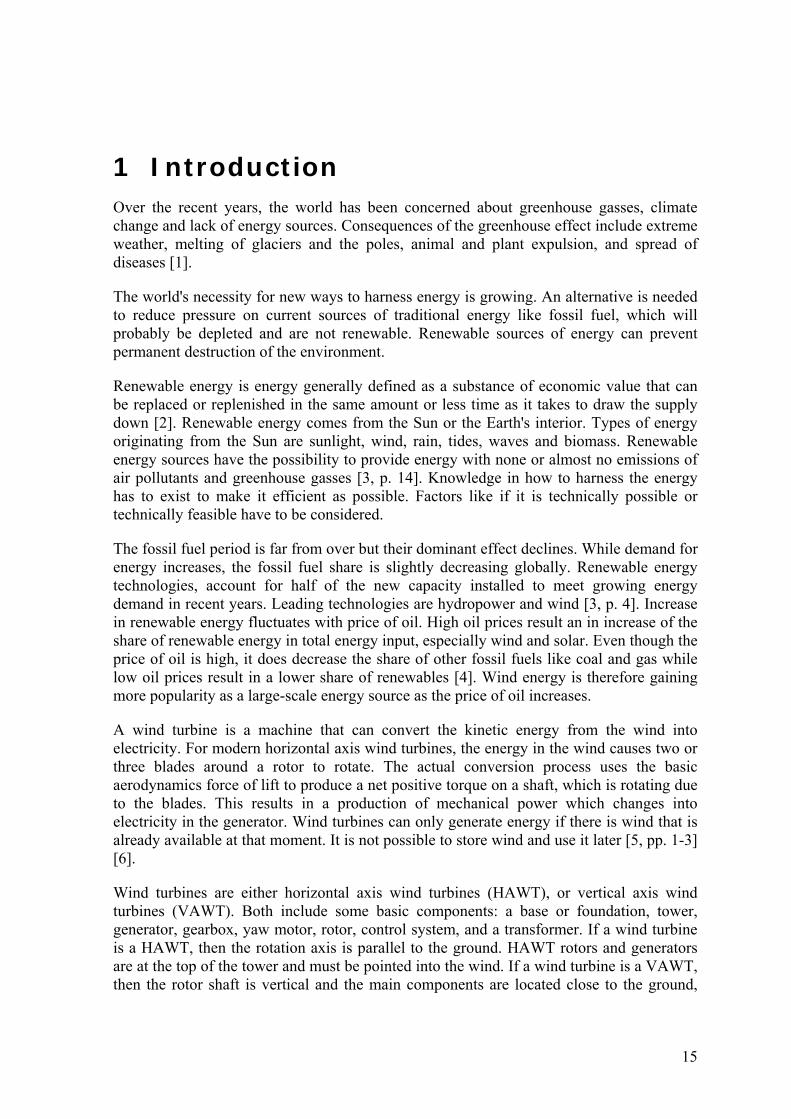
The cut-in-speed is when the turbine will start to generate power at its lower wind speed. This usually happens between 3.5 m/s and 5 m/s for HAWTs and varies between wind turbines. Also, as seen on Figure 3, when the wind rises above the cut-in-speed, the electrical output rises quickly. The power output will reach the limit the generator is capable of somewhere between 12 m/s and 17 m/s. This limit is called the rated power output and the rated output and the wind speed where this limit is reached is called the rated output wind speed. But the power output of the turbine is at maximum at that point. The design of the turbine is controlled to limit the power to this maximum level and the rise in output power stops. It varies depending on design how this goal is reached, but for bigger turbines, it is done by adjusting the angle of the blades. The cut-out speed is the wind speed where the wind turbine stops being able to increase its power output, even if the wind increases, and is usually around 25 m/s. This is based on the limit of what the alternator can achieve and beyond this point, there is a great danger of damaging the turbine and structure from high loads [14] [13] [15].
2.4 Lift and Drag Forces Two types of aerodynamic forces are created when an air flows over any surface: drag forces and lift forces. Drag force is in the airflow direction while lift force is right-angled to the airflow. Both lift and drag can generate forces needed to rotate the blades of a wind turbine.
Drag forces are used to generate vertical based wind turbines with Savonius and Darrieus rotors are use lift forces in the same purpose, where the force of the wind pushes against the surface [13].
25
Lift forces are used to generate horizontal based wind turbines by using lift instead of drag. Those wind turbines need specially shaped airfoil surfaces. This shape is designed to create pressure difference between upper and lower surfaces. This leads to a net force in the direction that is right-angled to the wind direction. Lift-drag rotors must be carefully oriented so they can maintain ability to harness the power from the wind as the wind speed changes [11].
• Lift turbines are those that have the blades designed as airfoils similar to aircraft wings. The apparent wind creates lift from a pressure differential between the upper and lower air surfaces. They are also more efficient than drag turbines [11].
• Drag turbines operate purely by the force of the wind pushing the blade [11].
2.5 Friction The roughness of the earth cause friction which has a significant effect on wind as high as 100 meters. The roughness of the surface and the speed of the wind determine the magnitude of the frictional force as the air closer to the ground is more affected by friction. Friction makes the air slow down, but as the height increases, the velocity of the wind increases since it becomes less affected by the roughness friction [16].
Since wind speed increases with height, the wind turbines are attached to a high tower in respect to the friction near the surface. The landscape is an important configuration when choosing a site. Factors like valleys, hills, bodies of water and other obstacles have a significant effect on the efficiency of the turbine.
2.6 Turbulence The word turbulence is used to describe instability or disturbance. It can also be used to refer to atmospheric instability, like unpredictable air movements coming from winds [17].
In order to station the wind turbine at a specific location, the characteristics of the turbine have to be understood. It is not sufficient to know the average wind speed for wind power utilization; the turbulence has to be analyzed. Locations that are economically viable for wind turbines have been proven otherwise because of unfavorable turbulence [18].
A strong turbulence has negative effect to the power production of wind turbines [18]:
The turbine must be able to handle peak loads that it will experience. In cases where the turbulence is high, the loads on the blades, gearbox, generator, and tower will also be high. Turbines that are designed with high turbulence tolerance, cost more and harness less energy.
Wind gusts that are turbulent, occur at random frequencies and speed. Fast changing loads have the potential to excite large vibrations in the turbine and the tower. Stiffer and stronger structures need to be able to overcome this.
Cyclic loads can lead to fatigue problems in the structure of the turbine. Blades that are moving through turbulent air are moving in conditions that are
constantly changing, meaning the blades of the turbine cannot compensate.

26
Most air that a turbine is affected by is turbulent. One reason being that as air moves over hills, it usually speeds up. This increased speed is due to a positive pressure gradient, which means that the push behind is greater that the resistance ahead, leading to a faster movement of air. This is the reason why most wind turbines are placed on ridges and on top of hills. However, at the other side of the hill, the opposite occurs and the air is affected by a negative pressure gradient. This leads to slower air and reverse direction of air. Turbulence forms when air high above the hill is moving in one direction and air at the hill is moving in the opposite direction. If the turbine is located downstream of the hill, the turbulence that is caused by the landscape will most likely affect the turbines [18].
Turbulence also decreases with height, as the influence of friction from the ground decreases. This can translate to increased wind speed with increased height. For the air at ground level to be stopped, and to be moving faster with height, the layers1 of air must be sliding over one another. This is called a shear. Air that is in a shear becomes more easily turbulent [18].
Another source of turbulence within the boundary layer is called a convection, or when the air in contact with warm ground surface is heated. As this air gets warmer, it becomes lighter and therefore rises [18].
It is impossible to find a location where turbulence because of landscape or boundary layers does not exist. But if the amount of energy in turbulence that occurs at a potential wind turbine location can be predicted, a better decision can be made if the location is profitable or not [18]. There are two key factors to predict the turbulence: steepness of the hill and the type of vegetation cover. The steeper the hill, the greater the turbulence generated behind it. When it comes to vegetation, the turbulence created is affected by canopy height, difference in height, and density of the vegetation [18].
Turbulence is the main factor that causes fatigue damage on major components of the turbine, but there are two different sources of turbulence. It can be generated by terrain features, also called ambient turbulence intensity, and by neighboring wind turbines, called induced turbulence. Ambient turbulence is caused by forest, hill, cliffs, thermal effects, and so on. It is possible to reduce the ambient turbulence by avoiding the terrain features that causes the turbulence. Turbulence caused by wake has more of an effect than the ambient turbulence intensity. By decreasing the space between turbines, the turbulence created by the wakes of neighboring turbines increases. If the turbines are stationed too close to another, the fatigue loads can be too high. To ensure the lifetime of the wind turbine, some wind turbines might have to be turned off when they are in operation and are suffering from the wake effect from neighboring turbines [19].
If there is high friction, and therefore high turbulence, the turbulence can also be avoided by building higher towers, or higher hubs. The manufactures offer several models with different tower/hub heights and rotor diameter as well as custom made turbines according the site and power output requirements.
1 Air that is affected by the surface of the Earth is called a boundary layer, for example by showing an increase in speed with heigh [18]

27
2.7 Angle of Attack The angle of attack plays an important role in shaping the performance of the turbine blades. The angle of attack is one factor in determining the performance of the wind turbine when it comes to determine the power output and over-speed induced stress protection. The blade must be twisted by an angle and not flat because in order to have a good lift force, the airflow must hit the blade at a proper angle. This angle is the angle of attack. [20] [21] [22, p. 53] [7, p. 122].
The airfoil of the blades uses lift to harness the motion of the wind. When the edge of the airfoil is angled out of the wind direction, the air moves faster on the downstream side of the blade, which creates a low pressure and lifts the airfoil upwards [23].
The amount of lift for a certain airfoil depends greatly on the angle that it makes with the direction of the relative wind, known as the angle of attack. Increased angle of attack means increased lift, but also more drag, which detracts from the desired motion. In cases where the angle of attack is too big, turbulence develops and drag increases greatly, but the lift is lost [23].
When it comes to wind turbines, the angle of attack can be changed by creating a specific geometry for the blades along the span, or letting the blades to rotate around the axis perpendicular to their cross section which is also along the span. In order to make the rotor rotate at a constant speed, it is important to change the angle of attack to maintain precise amount of lift [20].
2.8 Twist Angle The twist angle is dependent of TSR and angle of attack of the airfoil. The tip of the blade is not parallel to the root of the blade. The blade must be twisted by an angle and not flat because in order to have a good lift force, the airflow must hit the blade at a proper angle. The blades of the wind turbine have a built-in twist along the span because the blade has to have different angles of attack so the entire blade is able to feel a consistent force. The twist also limits stress on the blades [23].
2.9 Pitch Angle The role of a pitch angle is to maintain a near uniform rotor speed under different wind circumstances to achieve optimum power output from the turbine. The pitch angle the blades to maximize the capture of the energy. Only a small change in the pitch-setting angle can have a huge effect on the power output of the wind turbine. If a rotor is designed with a certain optimal operation in mind at a certain wind condition, then the pitch blade can adjust the wind turbine to other conditions [24, pp. 75, 105] [21] [22, p. 53] [7, p. 122].
After viewing parameters that affect or influence the performance of a wind turbine, the horizontal axis wind turbine will be presented in chapter three, along with critical components.


29
3 Horizontal Axis Wind Turbines In order for a turbine to be defined as a HAWT, the rotor blades have to be connected to a horizontal shaft. These types of turbines are mainly for commercial usage. Critical components are the rotor, gearbox, anemometer, generator, yaw motor, control system and the foundation. The turbine can either be a rotor-upwind design or rotor-downwind design. An upwind rotor faces the wind while a downwind rotor enables the wind to pass the tower and nacelle before it hits the rotor. The rotor diameter, number and twist angle of rotor blades, tower height, rated electrical power, and control strategy are the main considerations in design. A huge factor regarding the efficiency is the height of the tower since more height means more wind power [7, p. 36]. According to Equation( 10, the wind speed is in the third power meaning that more height equals more wind speed. Also, with increasing height, the turbine noise, rotor blades, and power output increases [7, p. 5] Rotor diameter (D) is of equal importance because it determines the area (A) needed to meet the output level which is needed in each case [7, pp. 33-37].
Upwind rotor design currently dominate the market [7, p. 36]. Even though the downwind rotor design adjusts automatically to wind direction, an important safety and operational feature, it does not adjust under abrupt or sudden changes in wind direction. This can be overcome with three-blade upwind rotor, making it more desirable than the downwind rotor [7, pp. 33-37] [5, pp. 3-5].
In order to optimize the power output performance, a selection of a ratio between the rotor diameter and the hub height has to be considered carefully. In order to avoid damage to the structure, the control system must ensure that the rated power output of a wind turbine does not exceed the maximum power allowed for the generator [7, pp. 33-37].
HAWT usually have two or three rotor blades. A turbine with two rotor blades is often in downwind installations where, the rotor is downwind on the tower. It is faster and cheaper, but it flickers more than the rotor with three blades and is less efficient. Three blade rotors operate more smoothly and are therefore less disturbing. HAWTs is lift based which means that they have blades designed as airfoils similar to aircraft wings. The apparent wind creates lift from a pressure differential between the upper and lower air surfaces [7, pp. 33-37] [13].
The main advantages is high generating capacity, improved efficiency, variable pitch blade capacity, and tall tower to capture large amount of wind energy. There are also disadvantages such as consistent noise, killing of birds, interference with radio, TV transmission and radar, land use, maintenance worker hazards and visual impacts [7, p. 5].

30
Figure 4: Lift-based wind turbine concept [13]
There are critical components when it comes to HAWT that need to be considered when it comes to design. They are listed in the sections below.
3.1 Tower The height of an HAWT tower is very important when it comes to performance since wind speed increases with height [7, pp. 36-37].
The interaction between wind speed and installation height is complicated. The wind is affected by friction from turbulence around mountains, hills, trees, buildings etc. These influences decrease with increasing height. In short, wind speed increases with more height and friction while turbulence decreases. Higher towers therefore offer more wind speed and it is possible to use larger blades that increase the production of electrical power. Low wind speed and changes in wind speed as a function of height, called wind shear, can have a harmful influence on the performance of the turbine. When a reversal in temperature occurs in a calm wind environment, the wind speed can increase slightly between the ground and certain height of the tower and then start to decrease. Meaning the change in wind speed as a function of height is not constant [7, pp. 55-57].
In the case of HAWT the tower must be high enough for the blades to not touch the ground as they rotate. But generally, the height of the tower is 1 to 1.5 times the rotor diameter [5, p. 7] [25]. A wind turbine should be practical for the operation in question and the height of the tower should be based on an economic tradeoffs of increased energy capture versus increased cost and the characteristics of the site [5, p. 257]. Figure 5 shows how much the rated power increases with bigger blades, which require taller towers.

31
Figure 5: Growth in size of typical commercial wind turbine (hub height in meters) [26]
There are various types of HAWT towers (few examples of wind turbine towers can be seen in Figure 6). Those are as follow [5, p. 257] [27] [28] [29] [30]:
Tubular towers (steel and concrete): Steel tubular towers are the most common used solution. They are made of steel plates that are welded together. This type has a diameter from 4.5 meters at the bottom to 2 meters at the top, divided into 3 or 4 parts, where they are bolted together at the site where the wind farm is located. They can vary from 30 to 40 meters. The new steel towers are more than 100 meters with a base diameter of over 5 meters, which can be a problem since many countries have a maximum transportable road size less than 4.9 meters. Unlike the lattice towers, they do not have bolted connections that need to be checked regularly for torque. Also, they have less of a visual effect than lattice towers. Concrete towers are used in countries where the price of steel is very high. They are made of smaller pieces put together at the site. They are easy to transport because they have smaller dimension of the components and it is easy to control the quality of the material, but they are heavy.
Lattice towers: This type was common when turbines were smaller. These types of towers are very strong, not expensive to manufacture, easy to transport and erect. Their biggest problem is the visual impact and maintenance cost.
Guyed wind tower: They take a scape because of the guy wires but are very strong and most economical, but they are only used for small turbines.
Tilt up wind towers: This type has a locking system making it easy to take down for repair. They are mainly used for consumer wind energy.
Free standing towers: Must to be used with cautions and for small wind turbines.

32
Hybrid: Used to reduce the cost when it comes to the unstable price in steel. The main problem being a higher installation cost and they are complicated to assemble.
Concrete towers for multi megawatt turbine: Because of increasing demand of growth in the sector, a development in order to improve power output is taking place. Steel towers have already reached their limits and concrete towers can raise towers from 80 to 100 meters and more. With towers that high, it is possible for the blades to receive more wind and current, where the towers have to carry larger turbines and rotor blades. There are some concrete towers already on the market. Acciona Windpower, has a 3 MW turbine that is possible to install using an 80 meter steel tower or a concrete towers of different lengths. The concrete tower can reach up to 120 meters high and is assembled in 5 or 6 section. This is a good choice in remote areas or in areas with aggressive environment like marine environments. It will also require less maintenance and is resistant to corrosion.
Figure 6: Various types of wind turbine towers [31]

33
The effects that come from loading must be considered when it comes to bending and buckling. There are two types of loads that can effect a tower [5, p. 309]:
Steady: steady tower loads happens from aerodynamically produced thrust and torque. There is also a load from the machine itself. There are two factors that the loading on the tower is estimated from.
1) Operating at rated power 2) Stationary at survival2 wind speed.
Dynamic: can be a great source of loads on both soft3 and soft-soft4 towers.
A tower should be designed so the natural frequency does not collide with excitation frequency of the turbine, from either the rotor frequency or the blade passing frequency.
The excitation frequencies should not be within the 5 percent of the natural frequency when the turbine is fully operational. A dynamic magnification factor should be used to multiply the design loads when the structure of the turbine is being elevated, where the operation is intended in a region where the excitation frequencies are between 30 percent and 140 percent of the natural frequency of the tower [5, p. 310]:
3.2 Foundation The foundation is not the first thing that comes to mind when thinking of a wind turbine. The foundation is usually underground for most parts with diameters ranging from approximately 15 – 21 meters [32]. Foundations are often underestimated but have to be a reliable components of the wind turbine in order for it not to tilt and collapse. Critical design factors include structural loads (extreme winds, normal operating winds and fatigue), materials, construction, geotechnical parameters, tower flange dimensions, and serviceability requirements (stiffness, settlement). Also, the mechanical and electrical factors have to be considered [33].
A geological assessment has to be made after choosing a site for the wind turbine and/or wind farms. Soil and rock characteristics are important issues when it comes to load factors because it is important to have knowledge of how the soil behaves and how it supports the wind turbine, and how it formed [32].
There are several types of foundations for wind turbines [32]:
Spread footing is the most common foundation and best suited in low compressed soil.
2 Maximum wind speed that a construction can withstand [94] 3 Soft tower: A soft tower has a natural frequency lower than the blade passing frequency but greater than the rotational frequency of the WT. 4 Soft-Soft Tower: A soft-soft tower has a natural frequency lower than the rotational frequency of the rotor.
34
Patented caisson is an embedded soil filled steel can mainly used in riverbeds and relies on skin friction of soil. It cannot be placed in all soil conditions due to movement of the soil.
Pile foundation is best to use in very compressed soil where it is drilled deep down to support the wind turbine. They are expensive and cost a lot in labor. If there is a poor soil at the site, this foundation is well suited.
Rock socket or rock anchor is attached to the rock. Rock socket foundation is more economical in shallow bedrocks rather than shallow spread foundations. Both types use less concrete and less steel. They cost less than other types but take longer to design, which is why investors rather choose spread footing foundation in order to keep schedule.
What has to be kept in mind is the bearing capacity of the soil has to be greater than the load, otherwise the foundation will sink and the system collapses. At some sites, the soil is very corrosive which has to be considered in cases where steel and concrete are being used.
3.3 Rotor The rotor is a critical element of a wind turbine. The rotor consists of rotor blades and the hub, which will be presented in more detail in following sections. The power production is dependent on its interaction with the wind.
The swept area, or surface area swept by the rotating blades, is the parameter that decides the size of the wind turbine. Equation 13, show the relationship between the swept area of the rotor and the diameter of the rotor [34, p. 3]:
0.785 ( 13 )
There are two types of rotors in HAWT, upwind and downwind rotors [7, p. 80].
Downwind and upwind rotors are best suited for turbines with high capacity and operating at high tip speed ratio [7, p. 80]. Downwind rotors, have free yawing, which is easier to implement than active yawing used by upwind rotors. Also, the downwind position reduces bending moment of the blade root flap. The main disadvantage is fatigue damage to the blades caused by periodic load leading to a wave on the generated electrical power. It is possible to decrease these effects by a teetering hub and individual pitching mechanism [35].
The advantage of upwind rotors is reduced tower shading and because the air starts to bend around the tower before it passes, the loss of power is less [36]. The main disadvantage is the extended nacelle needed to put the rotor in the right position to avoid a blade strike. Also, bad weather conditions may lead, to a stressed rotor hub by the blade [36].
TSR depends on the number of blades attached to the rotor. There are rotors with one or two blades, but three blades is most common one is the three bladed rotor but maximum capture of wind energy is only possible with large number of blades. The rotor must have rotational speed according to its size, which means correct rotor diameter and the wind speed. Or in other words, the rotor must have an efficient [7, p. 92]. Also, designers have

35
to keep in mind that by increasing the effective diameter of the rotor, the cost, weight, tower structural complexity and noise level will also increase [7, p. 238]. Studies shows that the TSR for rotors with two blades is 2 to 4 percent less efficient than the three blade rotor. There is even more drop when it comes to one blades rotor, or 6 percent less than the two bladed one. Also, is there an increase in cost and design complexity as the number of blades increase [7, p. 102].
The rotor has to rotate faster in proportion to the number of blades. The one bladed rotor has to rotate faster than three blades rotor to extract maximum power from the wind. Which means more tip noise and erosion [35] [7, p. 103].
There is a connection between the reliability of the rotor, TSR and number of blades. High speed ratio should have less blade area to be at optimum, than the rotor of a slower turbine. If the TSR increases the chord and thickness decreases for any given number of blades. This results in higher blade stresses. By reducing the number of blades, which means higher TSR, the weight of the rotor can also be reduced [35].
Rotors found in wind turbines consist of airfoils that generate lift by virtue of the pressure difference across the airfoil. The airfoil is a big influence in the performance of the rotor. Improvement in performance depends on several factors, for example, high lift-to-drag ratio to improve rotor efficiency over a wide range of wind environments, characteristics of the stall, less noise, insensitivity to roughness and, optimum shape of the rotor for better performance [7, p. 104]. Behavior of the airfoil changes depending on Reynolds numbers, which must be available for analysis of a wind rotor system to take place [5, p. 112].
Hydrodynamic flows analysis, which influences the performance of the rotor, can be predicted regardless of the shape. This analysis can predict the air movement over a solitary spherical hill. This type of analysis is important in order to understand the theoretical aspects and operating principles of a wind turbine [7, p. 104]. The rotor has to operate continuously, so the rotor has to be designed with that in mind because maintenance is both expensive and time consuming [7, p. 107]. There are some basic rotor parameters which need to be decided, the first one being what power, P, is needed at a specific speed, v. Also, the rotor power coefficient, Cp and the efficiencies of other components like, gearbox, generator and pump. Next, a TSR, λ, is chosen. The value for an electric power generation is between 4 and 10 [5, p. 125]. There is less material in the blades for machines at higher speed but they need a more sophisticated airfoil design, and smaller gearboxes. A number of blades can be chosen from Table 2 [5, p. 125].
Table 2: Different number of blades for various TSR [5, p. 125]
B1 8-24 2 6-12 3 3-6 4 3-4 >4 1-3
36
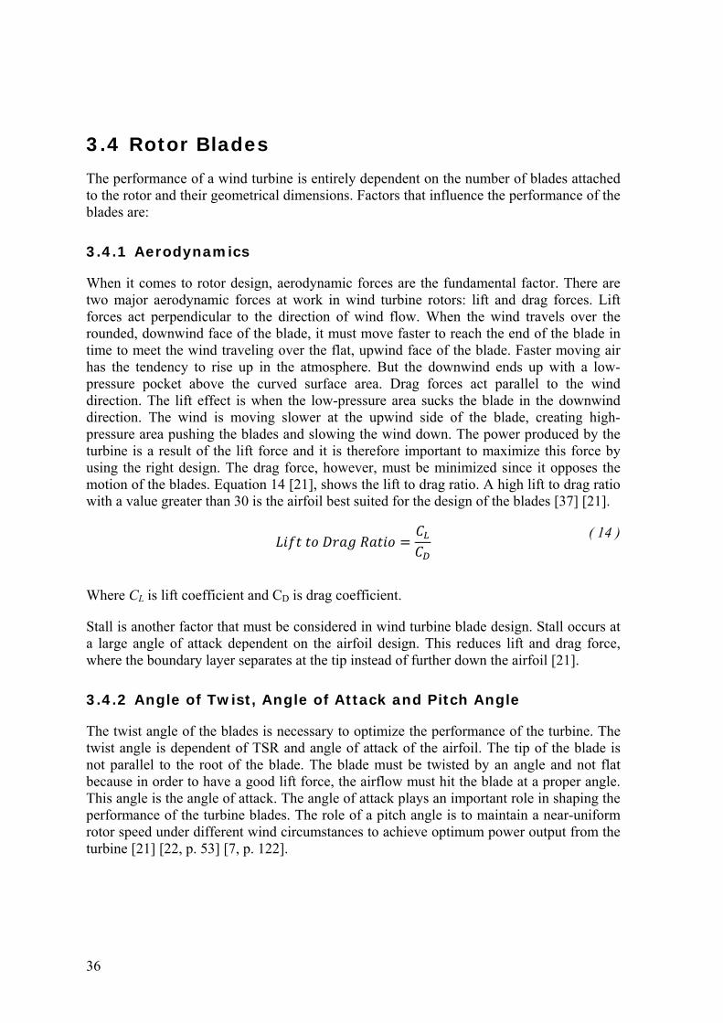
3.4 Rotor Blades The performance of a wind turbine is entirely dependent on the number of blades attached to the rotor and their geometrical dimensions. Factors that influence the performance of the blades are:
3.4.1 Aerodynamics
When it comes to rotor design, aerodynamic forces are the fundamental factor. There are two major aerodynamic forces at work in wind turbine rotors: lift and drag forces. Lift forces act perpendicular to the direction of wind flow. When the wind travels over the rounded, downwind face of the blade, it must move faster to reach the end of the blade in time to meet the wind traveling over the flat, upwind face of the blade. Faster moving air has the tendency to rise up in the atmosphere. But the downwind ends up with a low-pressure pocket above the curved surface area. Drag forces act parallel to the wind direction. The lift effect is when the low-pressure area sucks the blade in the downwind direction. The wind is moving slower at the upwind side of the blade, creating high-pressure area pushing the blades and slowing the wind down. The power produced by the turbine is a result of the lift force and it is therefore important to maximize this force by using the right design. The drag force, however, must be minimized since it opposes the motion of the blades. Equation 14 [21], shows the lift to drag ratio. A high lift to drag ratio with a value greater than 30 is the airfoil best suited for the design of the blades [37] [21].
( 14 )
Where CL is lift coefficient and CD is drag coefficient.
Stall is another factor that must be considered in wind turbine blade design. Stall occurs at a large angle of attack dependent on the airfoil design. This reduces lift and drag force, where the boundary layer separates at the tip instead of further down the airfoil [21].
3.4.2 Angle of Twist, Angle of Attack and Pitch Angle
The twist angle of the blades is necessary to optimize the performance of the turbine. The twist angle is dependent of TSR and angle of attack of the airfoil. The tip of the blade is not parallel to the root of the blade. The blade must be twisted by an angle and not flat because in order to have a good lift force, the airflow must hit the blade at a proper angle. This angle is the angle of attack. The angle of attack plays an important role in shaping the performance of the turbine blades. The role of a pitch angle is to maintain a near-uniform rotor speed under different wind circumstances to achieve optimum power output from the turbine [21] [22, p. 53] [7, p. 122].

37
Figure 7: Various types of turbine blades with different twists [38]
3.4.3 Tip Speed Ratio
As stated before, the tip speed ratio is an important parameter selected in the design of every wind turbine. Greater TSR implies a greater power coefficient. The TSR is the relationship between rotor blade velocity and the relative wind speed.
The TSR depends on the number of blades of the rotor as seen in Table 2. When choosing an appropriate tip speed, there are some design considerations when it comes to efficiency, torque, mechanical stress, aerodynamics and noise [21]. Table 3 illustrates some design considerations. Torque and area of solidity both increase when the tip speed is low, but decreases when the tip speed is high. Efficiency and centrifugal stress decrease when the tip speed is low and, increase when the tip speed is high.
Table 3: Tip speed design considerations
Low High Centrifugal stress Decrease Increase Area of solidity Increases Decreases Efficiency Decreases Increases Torque Increases decreases
It is worth mentioning that that the blade profile is rather large for low tip speed but rather narrow at high tip speeds since the blade demands reduced chord widths. This reduction will lead to less material and lower production costs. Aerodynamics is quite simple for low tip speed but complex and critical when it comes to high tip speed. A blade designed for a high relative wind speed develops minimal torque at lower speeds. As a result, the cut-in speed increases [21] [7, pp. 92-96].

38
3.4.4 Blade Plan Shape and Quantity
The blade element momentum method, or BEM, is a combination of two methods. In the first method, a momentum balance is used on a rotating annular stream tube passing through a turbine. The other method examines those forces that generate because of the airfoil lift and drag coefficients at different places along the blade. Its purpose is to examine how a wind turbine operates [39].
The BEM method, analyzes the performance of the rotor when it comes to the blades. The BEM method can be used both for HAWT and VAWT [40].
The method assumes that the blade can be analyzed as many independent elements in span-wise direction. The velocity of each of those elements is determined by doing a momentum balance for an annular control volume containing the blade element. The lift and drag coefficient, which come from the two-dimensional wind tunnel test data, are used to calculate the aerodynamic forces on each of those elements. The BEM method is a great tool for designers. However, the BEM method is not accurate enough when it comes to the wake effect estimation [40].
The BEM method is used to calculate the chord length, local air velocities and airfoil lift according to the Betz limit. The ideal form of a HAWT rotor blades can then be defined. The Betz method gives the basic shape of a wind turbine blade. In cases were the TSR is from 6 to 9, or a high tip speed, airfoil sections with negligible drag and tip losses are used. When the tip speed is low, this method is accurate when considering high drag airfoil sections and blade sections around the hub. As seen in Figure 8, the blades become slimmer as the TSR becomes larger. When constructing such blades, there arise problems with strengths and stiffness. Therefore, high speed rotors must have a small number of blades. A reason for building a single-blade rotor is that it is possible to get high speed rotors with a reasonable blade aspect ratio [41, p. 137] [21].

39
Figure 8: Optimal blade plan shape for alternate design TSR and corresponding number of blades [21] [41].
Even though the efficiency of a four-bladed wind turbine increases, it does not increase enough to justify the cost of manufacturing an extra blade. There is also a question if the tower can handle the extra load. Whether there are; one, two, three or four blades, all lead to increased dynamic loads. The three-bladed design is the leading design in the world, both because of proportional efficiency and visual effect because. It rotates more smoothly while the one- and two-bladed wind turbines fluctuate more. When using fewer blades it reduces the rotor nacelle weight and manufacture cost. [21] [7].
When it comes to choosing a material for the rotor blades, there are a few options. For high capacity wind turbines, wood laminates, glass-reinforced plastic, carbon fiber-reinforced plastic, steel, and aluminum are the common materials used. How material is chosen depends on the mechanical and structural properties of the fabrication. The ideal material when designing the blade are high strength to weight ratio, fatigue life and stiffness with low cost and material that can be easily molded into the desired airfoil shape. In cases where there is a small turbine, or less than 5 diameter (m), there are other considerations when choosing a fabrication material. Production efficiency and fabrication cost are more important than weight, stiffness, and other design requirements [7, p. 103] [24, p. 386].
When designing longer blades, decrease in weight and increase in stiffness are crucial requirements. Carbon fiber-reinforced plastic, has lowest weight and highest stiffness, but this material is expensive. As demand increases for this material, manufactures are hoping for lower price in the near future and increase its usage [7, p. 103].

40
3.5 Rotor Hub Hub height is the height from the ground to the center of the rotor and is a heavy component of the wind turbine. The hub connects the blades to the main shaft and drive train and must withstand all loads from the blades [5, p. 292].
The hub is rigid, hinged or teetering and is usually made of ductile cast iron. The hub is covered by a cone in order to prevent is from the environment and for visual effects. The material used for constructing the cone has similar composites as used in the blades [42].
The design of the rigid hub keeps all the major parts in place relative to the main shaft. It does not exclude the blade pitch, but does not allow other blade motion. The rigid hub has to be strong enough to endure loads forming from aerodynamic and dynamically induced loads (rotation, yawing) on the blades [5, p. 292] [43].
For two-bladed wind turbines, teetering hub is used. This hub can reduce loads due to imbalance in aerodynamic loads caused by the dynamic effect from rotation of the rotor or yawing of the turbine. This type of hub is more complicated than rigid hubs. In normal operation, the teetering hub will move a few degrees forward and backwards. But in bad weather conditions like high winds, it starts and stops and a greater teeter can take place. There are teeter dampers to prevent damage under those conditions [43].
A hinged hub is a combination of the two hubs mentioned above: a rigid hub with hinges for the blades. The hinges, however cause some difficulties. The teetering hubs, used for two blades, tend to balance each other, so the lack of centrifugal stiffening during low rpm operation is an advantage. This is not the case for a hinge blade, so there has to be some mechanism to prevent the blades from flopping over during low rotational speed [43].
Figure 9: Hub options [44]
3.6 Control System To be able to achieve dynamic stability and both safe and reliable operation under various wind conditions, control systems are needed.
41
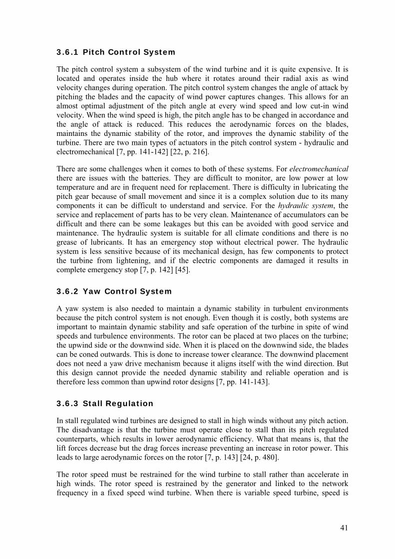
3.6.1 Pitch Control System
The pitch control system a subsystem of the wind turbine and it is quite expensive. It is located and operates inside the hub where it rotates around their radial axis as wind velocity changes during operation. The pitch control system changes the angle of attack by pitching the blades and the capacity of wind power captures changes. This allows for an almost optimal adjustment of the pitch angle at every wind speed and low cut-in wind velocity. When the wind speed is high, the pitch angle has to be changed in accordance and the angle of attack is reduced. This reduces the aerodynamic forces on the blades, maintains the dynamic stability of the rotor, and improves the dynamic stability of the turbine. There are two main types of actuators in the pitch control system - hydraulic and electromechanical [7, pp. 141-142] [22, p. 216].
There are some challenges when it comes to both of these systems. For electromechanical there are issues with the batteries. They are difficult to monitor, are low power at low temperature and are in frequent need for replacement. There is difficulty in lubricating the pitch gear because of small movement and since it is a complex solution due to its many components it can be difficult to understand and service. For the hydraulic system, the service and replacement of parts has to be very clean. Maintenance of accumulators can be difficult and there can be some leakages but this can be avoided with good service and maintenance. The hydraulic system is suitable for all climate conditions and there is no grease of lubricants. It has an emergency stop without electrical power. The hydraulic system is less sensitive because of its mechanical design, has few components to protect the turbine from lightening, and if the electric components are damaged it results in complete emergency stop [7, p. 142] [45].
3.6.2 Yaw Control System
A yaw system is also needed to maintain a dynamic stability in turbulent environments because the pitch control system is not enough. Even though it is costly, both systems are important to maintain dynamic stability and safe operation of the turbine in spite of wind speeds and turbulence environments. The rotor can be placed at two places on the turbine; the upwind side or the downwind side. When it is placed on the downwind side, the blades can be coned outwards. This is done to increase tower clearance. The downwind placement does not need a yaw drive mechanism because it aligns itself with the wind direction. But this design cannot provide the needed dynamic stability and reliable operation and is therefore less common than upwind rotor designs [7, pp. 141-143].
3.6.3 Stall Regulation
In stall regulated wind turbines are designed to stall in high winds without any pitch action. The disadvantage is that the turbine must operate close to stall than its pitch regulated counterparts, which results in lower aerodynamic efficiency. What that means is, that the lift forces decrease but the drag forces increase preventing an increase in rotor power. This leads to large aerodynamic forces on the rotor [7, p. 143] [24, p. 480].
The rotor speed must be restrained for the wind turbine to stall rather than accelerate in high winds. The rotor speed is restrained by the generator and linked to the network frequency in a fixed speed wind turbine. When there is variable speed turbine, speed is

42
maintained by matching the torque of the generator to the aerodynamic torque. Wind turbines with variable speed offers the possibility to slow the rotor down in high winds to bring it to stall, resulting in higher aerodynamic efficiency, because the turbine can operate further away from the stall point in low winds. The disadvantage is, when gusts hit the turbine, the load torque has to rise in order to match wind torque. Furthermore, the load torque has to increase further in order to put the rotor into stall. Because of this, the stall regulation is rarely used for large commercial turbines, but many smaller and older wind turbines are stall regulated [24, p. 480].
3.7 Anemometer There must be accurate measurement of wind parameter for the pitch and yaw control systems to maintain dynamic stability operate reliably under all sorts of wind environments. Gathering accurate data of wind speed can be a problematic but important because it is used in conducting performance of turbines. This information are gathered with anemometers, which play key roles in providing the systems with this data. The wind turbine cannot work without measuring the wind speed and direction. Anemometers are placed at the back and top of the turbine and can been seen on Figure 10 [7, p. 143] [22, pp. 274-276].
There are two types of anemometer that are used: cup or ultrasound anemometers.
The cup anemometer consists of three cups placed on a small vertical shaft. When the wind blows the device rotates and the wind speed conducts the speed of revolution. At the end of the shaft is a DC device that generates signal of a different voltage, where the voltage is used as a measurement of the wind speed. The cup anemometer is associated with a wind wane, a simple device, which rotates about a vertical axis. The vane has a tail that orients the vane with the wind direction. In newer models there is a direction monitor located near the anemometer, which serves the same purpose [22, pp. 274-276] [7, p. 143].
Figure 10: Shows the placement of a cup anemometer on the turbine [46].
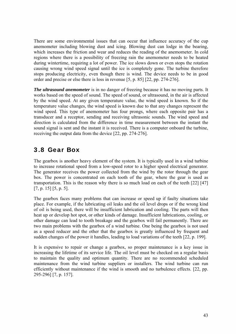
43
There are some environmental issues that can occur that influence accuracy of the cup anemometer including blowing dust and icing. Blowing dust can lodge in the bearing, which increases the friction and wear and reduces the reading of the anemometer. In cold regions where there is a possibility of freezing rain the anemometer needs to be heated during wintertime, requiring a lot of power. The ice slows down or even stops the rotation causing wrong wind speed signal until the ice is completely gone. The turbine therefore stops producing electricity, even though there is wind. The device needs to be in good order and precise or else there is loss in revenue [5, p. 85] [22, pp. 274-276].
The ultrasound anemometer is in no danger of freezing because it has no moving parts. It works based on the speed of sound. The speed of sound, or ultrasound, in the air is affected by the wind speed. At any given temperature value, the wind speed is known. So if the temperature value changes, the wind speed is known due to that any changes represent the wind speed. This type of anemometer has four prongs, where each opposite pair has a transducer and a receptor, sending and receiving ultrasonic sounds. The wind speed and direction is calculated from the difference in time measurement between the instant the sound signal is sent and the instant it is received. There is a computer onboard the turbine, receiving the output data from the device [22, pp. 274-276].
3.8 Gear Box The gearbox is another heavy element of the system. It is typically used in a wind turbine to increase rotational speed from a low-speed rotor to a higher speed electrical generator. The generator receives the power collected from the wind by the rotor through the gear box. The power is concentrated on each tooth of the gear, where the gear is used as transportation. This is the reason why there is so much load on each of the teeth [22] [47] [7, p. 15] [5, p. 5].
The gearbox faces many problems that can increase or speed up if faulty situations take place. For example, if the lubricating oil leaks and the oil level drops or if the wrong kind of oil is being used, there will be insufficient lubrication and cooling. The parts will then heat up or develop hot spot, or other kinds of damage. Insufficient lubrications, cooling, or other damage can lead to tooth breakage and the gearbox will fail permanently. There are two main problems with the gearbox of a wind turbine. One being the gearbox is not used as a speed reducer and the other that the gearbox is greatly influenced by frequent and sudden changes of the power it handles, leading to load variations of the teeth [22, p. 199].
It is expensive to repair or change a gearbox, so proper maintenance is a key issue in increasing the lifetime of its service life. The oil level must be checked on a regular basis to maintain the quality and optimum quantity. There are no recommended scheduled maintenance from the wind turbine suppliers or installers. The wind turbine can run efficiently without maintenance if the wind is smooth and no turbulence effects. [22, pp. 295-296] [7, p. 157].

44
3.9 Nacelle The nacelle is a housing or a box located at the top of the tower and serves as a protection from the environment for some major components like the generator and the gearbox. The nacelle consists of a floor called bedplate, where the equipment is placed, and the roof, or main enclosure, to frame the components [5, p. 320] [22, p. 296].
The nacelle must be strong enough to handle a number of loads. The force of all of the components, including the rotor, are transferred through the nacelle and to the tower. The aerodynamic forces also go through the nacelle. The nacelle must also handle the torque from the rotor to the tower [22, p. 296].
Moisture, a main source of damage, must be taken under consideration in wind turbines. The surface inside the turbine is well protected by various coatings and paint but moisture still can take place and damage due to moisture can take many years to develop. Any moisture that is inside the structure of the turbine increases the danger of corrosion, bacterial growth and condensation. These factors cause short-circuiting and damage to the electronics. Condensation is a big problem in wind turbine. When the air inside the tower has a lower dew point than the surface then that situation can cause condensation where the inner surfaces are wet. One way to handle that situation is by using dehumidification. By reducing the amounts of moisture in the air it also reduces the dew point. If the surfaces temperature in the tower is higher than the dew point then condensation will not take place in the nacelle. There are also fire hazards when it comes to wind turbines. Fire usually takes place by lightening or via technical fault. The nacelle cover is usually made of plastics like fiberglass which are highly flammable. A combination of radiant heat or a spark with the transmission fluids or other lubricants can therefore be dangerous [48] [49].
3.10 Heat Exchanger The components and systems inside the nacelle are necessary to convert mechanical energy into electricity. These systems and components generate a lot of heat inside the nacelle and need cooling. Excessive heat causes lubrication to break down and materials to expand, which in turn causes more friction and heat, leading to frequent lubricant replacement and gearbox repair. This heat has to be changed into the outside ambient air for efficient operation of the components inside the nacelle. Heat exchangers are used for this purpose and they can be air-to-air or air-to-water heat exchangers requiring pumps or fans as well as piping arrangements to circulate the water. Heat from power electronics is normally converted to outside ambient air by a water-cooled system, where the water is circulated between a cold plate and a surface of the electronics. Water-cooling has become more dominant than air-cooling because it is more effective, but water-cooling has some disadvantages. Water is conductive, and if there would be a system leak, the effectiveness of the system would be put in danger. Also, the water could damage or destroy any electronics, like controllers and sensors. There is also a problem with freezing but the standard approach is to add ethylene glycol to the water to prevent this [50] [51].
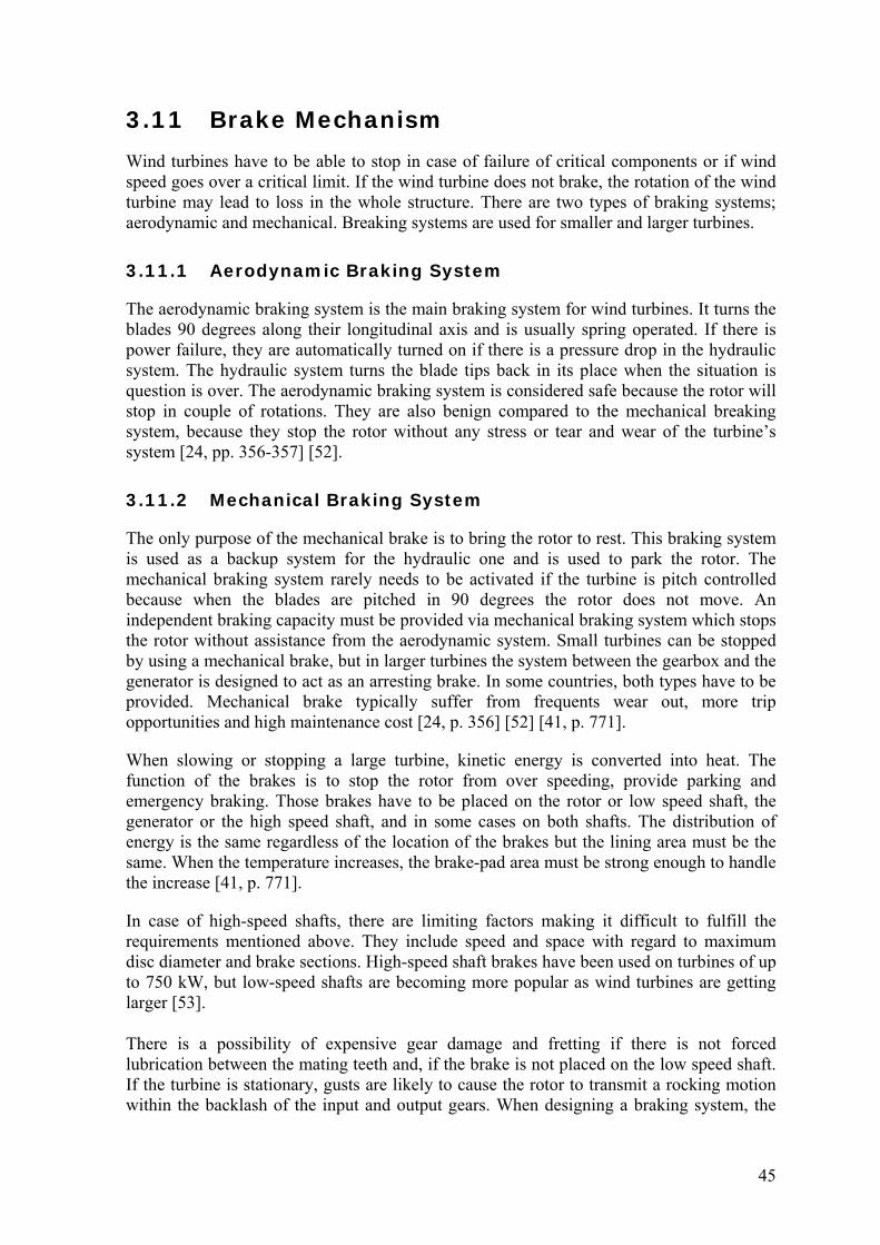
45
3.11 Brake Mechanism Wind turbines have to be able to stop in case of failure of critical components or if wind speed goes over a critical limit. If the wind turbine does not brake, the rotation of the wind turbine may lead to loss in the whole structure. There are two types of braking systems; aerodynamic and mechanical. Breaking systems are used for smaller and larger turbines.
3.11.1 Aerodynamic Braking System
The aerodynamic braking system is the main braking system for wind turbines. It turns the blades 90 degrees along their longitudinal axis and is usually spring operated. If there is power failure, they are automatically turned on if there is a pressure drop in the hydraulic system. The hydraulic system turns the blade tips back in its place when the situation is question is over. The aerodynamic braking system is considered safe because the rotor will stop in couple of rotations. They are also benign compared to the mechanical breaking system, because they stop the rotor without any stress or tear and wear of the turbine’s system [24, pp. 356-357] [52].
3.11.2 Mechanical Braking System
The only purpose of the mechanical brake is to bring the rotor to rest. This braking system is used as a backup system for the hydraulic one and is used to park the rotor. The mechanical braking system rarely needs to be activated if the turbine is pitch controlled because when the blades are pitched in 90 degrees the rotor does not move. An independent braking capacity must be provided via mechanical braking system which stops the rotor without assistance from the aerodynamic system. Small turbines can be stopped by using a mechanical brake, but in larger turbines the system between the gearbox and the generator is designed to act as an arresting brake. In some countries, both types have to be provided. Mechanical brake typically suffer from frequents wear out, more trip opportunities and high maintenance cost [24, p. 356] [52] [41, p. 771].
When slowing or stopping a large turbine, kinetic energy is converted into heat. The function of the brakes is to stop the rotor from over speeding, provide parking and emergency braking. Those brakes have to be placed on the rotor or low speed shaft, the generator or the high speed shaft, and in some cases on both shafts. The distribution of energy is the same regardless of the location of the brakes but the lining area must be the same. When the temperature increases, the brake-pad area must be strong enough to handle the increase [41, p. 771].
In case of high-speed shafts, there are limiting factors making it difficult to fulfill the requirements mentioned above. They include speed and space with regard to maximum disc diameter and brake sections. High-speed shaft brakes have been used on turbines of up to 750 kW, but low-speed shafts are becoming more popular as wind turbines are getting larger [53].
There is a possibility of expensive gear damage and fretting if there is not forced lubrication between the mating teeth and, if the brake is not placed on the low speed shaft. If the turbine is stationary, gusts are likely to cause the rotor to transmit a rocking motion within the backlash of the input and output gears. When designing a braking system, the

46
braking torque level for the rotor brakes can be calculated. The maximum torque on the brakes is imposed by the blades or the high-speed shaft. On the other hand, there is a minimum torque level on the brakes because of different kinds of weather conditions creating frictional forces that could put the rotor at risk. There must be a service factor that ensures that the brakes will operate under all climate conditions. A common value of the service factor is 2 [53].
3.12 Low-Speed Shaft and High-speed shaft The main function of shafts is to transfer torques. The low-speed shaft and the high speed shaft are important components in producing electricity and their function is connected. When the rotor is rotating, the low-speed shaft rotates according to the speed of the rotor. The gearbox then converts the low-speed shaft rotation to a higher rotation of the high-speed shaft. The high-speed shaft is connected to the generator, which converts mechanical energy into electrical energy. The most common design problem for these shafts bending and fatigue due to the loads they endure. Shafts also have natural frequencies at ‘critical speeds’. Those speeds have to be avoided in order to avoid large vibrations. The most common material used in shafts is carbon steel or alloy steel, but alloy steel is used under severe conditions [7, p. 15] [5, pp. 263-264]. The low-speed shaft and bearings transfer weight and load forces from the tower head system. The rotor transfers the forces and loads through the low-speed shaft to the gearbox. The rotor is supported be the low-speed shaft, becoming part of the turbine load path for both gravitational weight and thrust loads on the bedplate of the nacelle. The transfer of those loads reduces the shear forced on the gearbox [54, pp. 98-100].
The low speed shaft can either be solid or hollow. When the shaft is hollow, it becomes a path for blade pitch equipment, and hydraulic and electrical control signals from the turbine to the hub [54, pp. 98-100].
3.13 Electrical Generator Electrical generators convert mechanical power into electrical power. The generators that are used in HAWT are synchronous or induction generators, but induction generators are usually chosen because of torsional compliance and extraction of damping energy in the drive train. The reason why is the cyclic variations in the torque developed in the aerodynamic rotor [24, p. 365].
3.13.1 Induction Generators
The induction generator has a non-rotating component called stator which is connected to the network or load. In order to reduce noise and electrical losses, the stator has a three-phase winding on a laminated iron core. Their function is to produce a magnetic field that rotates at a constant speed. Though the induction generator and the synchronous generator have similar stators, their rotor configurations are very different [7, p. 144].

47
Induction generators are more reliable and are not expensive. They also have some mechanical properties that suit wind turbines. The rotor has a number of aluminum bars and those bars are connected to electricity by aluminum end rings. The speed of the generator changes according to the rotor speed. Induction generators also go under the name asynchronous generators because they operate asynchronous to the synchronous speed. When the torque changes the generator will increase or decrease its speed. Because of this, there is less wear and tear on the tower, gearbox and other components in the transmission line, or lower peak torque. That is one of the most important reasons for choosing an asynchronous generator rather than synchronous generator. The smaller wind turbines also use induction generators for the same reasons but mainly because they are inexpensive [55].
3.13.2 Synchronous Generators
The synchronous generator also has a stator with the same function as the induction generator. The rotor for this type of generator has field winding to carry a direct current, which creates a magnetic field. The rotating field, which is created by the stator winding, interfaces into the magnetic field. This leads to the rotor rotating at a constant speed with the stator field and the frequency of the network [7, p. 144].
The synchronous generator is with the stator to DC-link converter system. The generator is dependent from the revolution number. The output voltage from the generator has to be transformed over a bridge rectifier in to voltage of the DC kind. This DC voltage is then transformed to AC voltage and shaped into a voltage that fits the grid when it comes to amplitude and frequency. This process makes it possible for the power production to produce from a low number of revolutions up to maximum speeds. The rotor field has to be controlled from its own converter. The generator operates at a wide speed range. But even so, this construction of the system is complicated and therefore expensive [55].
3.14 Yaw System The nacelle does not rotate with respect to the rotor, but with respect to the tower. This rotating motion is provided by the yaw system and is necessary because the wind direction is not fixed. The yaw system directs the turbine in respect to the wind and consists of yaw bearing, yaw motor and yaw drive [22, p. 75].
The yaw system can either be active or passive which is determined by the rotor type, upwind or downwind. The downwind rotors use passive yaw system (free yaw), where the turbine follows the wind like a weather vane and is self-aligned to the wind. The blades are usually coned a few degrees in the downwind direction so the yaw system will work more efficiently. The active system sometimes uses yaw dampers in order to limit the yaw rate and as a result, limit the gyroscopic loads that take place in the blades. The upwind rotors use active yaw system, which include a yaw motor (one or more) that drives a pinion gear against a bull attached to the yaw bearing, gears, and a brake to keep the turbine stable when it is properly aligned. When using an active yaw system, the tower must be able to resist the torsional loads that come from the system. This mechanism is controlled by an automatic yaw control system with the wind sensors placed on the nacelle [5, pp. 6,255,283].

48
3.14.1 Yaw Bearing
Both active and passive systems have some sort of yaw bearing. The yaw bearing connects the main frame to the tower. In turbines with active yaw system, there is just the yaw bearing, where the yaw bearing must include gear teeth. As with all other bearings in wind turbines, the bearing has to carry the weight of the main part of the turbine, as well as transmit thrust loads to the tower. When designing a bearing it is important to consider the load the bearing has to endure and number of revolutions it has to be able to handle. The yaw bearing has to handle static and dynamic loads and be corrosion and wear resistant [5, pp. 6,266,306-307].
3.14.2 Yaw Motor
The yaw motor plays a critical role in the performance of the turbine under uncontrollable and unpredictable wind environments. The yaw motor is controlled by the control system to turn the rotor in the right direction, facing the wind. When the turbine is experiencing rotor blade instability or movement it will try to tilt the nacelle over the tower but the yaw motor tries to turn the nacelle back on the right place at the tower. The mechanical stability at the root of the tower can be disturbed by two bending moments under bad or moderate wind conditions. The turbine blade stability can also be affected by the yaw motor bending moments and atmospheric turbulence. Cyclic load is the main load to be considered when designing a wind turbine [7, pp. 15-16,131].
3.14.3 Yaw Drive
The yaw drive rotates the nacelle with respect to the tower on its rotating bearing. The yaw drive does this to let the turbine face the wind and to unwind the power and other cables when they become twisted. There are usually one or more motors, either hydraulic or electric, which are put on the nacelle. Each motor drives a pinion that is connected to a vertical shaft through the gearbox. The pinion is connected with gear teeth, which can be on the inside or outside the tower. In smaller turbines are, stationed outside the tower due to limited space and there they do not produce safety hazards [24, pp. 453-454].
Upwind rotor turbines use active yaw drive which contains one or more yaw motors. Downwind rotors align themselves with the wind direction and therefore do not need to use a yaw drive. When a rotor is not aligned to the wind, the turbine has a yaw error, meaning that a lower share of the wind energy will be running through the rotor area. The yaw drive can then control the power output. There is also the part were the rotor is closest to the source direction of the wind, which is subjected to a larger force than the rest of the rotor, or bending torque. The rotor then has the tendency to automatically yaw against the wind, both upwind and downwind turbines, and the blades will be bending back and forth for every time the rotor is rotating. When wind turbines are running with a yaw error, they will suffer from larger fatigue loads [7, p. 6] [56].
This chapter describes the horizontal axis wind turbine and its critical components. If the wind turbine is a HAWT, the rotor blades are connected to a horizontal shaft. Careful attention needs to be paid to critical components of a HAWT and their operating functions.

49
Those components were covered in the chapter. Those components are the tower, foundation, rotor, hub, blades, control system, anemometer, gearbox, nacelle, heat exchanger, brake mechanism, low- and high-speed shafts, generator and, the yaw system. The parameters that affect the performance, covered in chapter two, are put context with appropriate components.
In the next chapter, the vertical axis wind turbine will be presented. The three main categories will be presented along with various types of the VAWTs.


51
4 Vertical Axis Wind Turbines HAWT and VAWT have some common components but their configurations are not the same. One of the major advantages of the VAWT include the fact that they are cross-flow devices and therefore accept wind from any direction, so there is no need of yaw drive mechanism which is an expensive component used in HAWT [57, p. 303]. Also, the drive train, which includes the generator, the gearbox and the brake, is located at the ground of the base of the tower, making maintenance easier. When it comes to blade design, the blades can have a constant chord and no twist, making the blades simple and cheap to produce. They can be built lower, making them less visual and they can withstand harsher environments and do not need to be shut down in high wind speeds. But there are also disadvantages including the tendency to stall under gusty wind conditions [7, p. 38]. The blades are sensitive to fatigue due to the wide variation in applied forces during each rotation. Also, they have a low starting torque, dynamic stability problems and low installation height limiting operation to lower wind speed environments [7, pp. 37-38] [58, pp. 60-62] [59].
HAWT and VAWT have some of the same components including the rotor, which converts the wind energy into mechanical power. Also, the tower, which supports the rotor, and a gearbox to adjust the rotational speed of the rotor shaft for the generator or the pump. They also both have a control system that monitors operation of the turbine in automatic mode. And finally, the foundation to prevent the turbine to collapse during high winds. VAWT sometimes guy wires used with the foundation [34, p. 2]. The swept area, or the surface area swept by the rotating blades is the parameter that decides the size of the wind turbine. Equation 15 shows how the swept area or the rotor is determined from the diameter of the rotor. For a typical VAWT the aspect ratio is 1.5 (height/diameter) [34, p. 3]:
1.00 ( 15 )
An important parameter for performance of a wind turbine is the power coefficient. The maximum theoretical efficiency of a HAWT, called the Betz limit, is approximately 0.59, and does not apply to VAWT because the arguments that are used to derive the Betz limit for a HAWT do not apply directly to a VAWT. VAWT can accept wind from any direction, so the power coefficient has to be calculated differently that in HAWT. The equation is as follow [60]: 2
60 2
( 16 )
Where, PM is the mechanical power produced by the wind turbine (W), Pwind is the power of the wind stream (W), N is rotational speed (RPM), F is tangential force acting on the pulley, ρ is density of air (kg/m3), A is cross section area of the swept (m2), and v is wind speed (m/s)

52
In turbulent conditions with gusty winds (rapid changes in wind direction) in urban environments, VAWT will generate more electricity despite its lower efficiency. Also, the VAWT is designed to operate near the ground where wind power is lower and produce drag on the blades as they rotate. In short, the VAWT is good for a low-wind turbulent environment [61].
Even though HAWT are usually more efficient in converting wind energy into electrical energy and are more utilized for commercial usage, VAWT are more suited in urban areas because they are silent and there is less risk due to slower rotation [59]. The VAWT has not yet gained the same popularity for large scale power production as the HAWT. In order to spread the use of VAWT some problems need to be overcome, including poor self-starting and low initial torque, low power coefficient, and poor building integration. Currently, large scale VAWTs are not considered economically attractive, but they offer energy solutions for remote areas away from grid systems, and areas where large wind farms cannot be placed because of environmental concerns and scattered units are preferred. This is the reason why a mass production of VAWTs been started as a small scale generating units [62]. Conclusions that can be made according to Bhutta [62]:
There is enough wind energy available on Earth, and to utilize it as possible, wind turbine designs need to be developed.
Various types of VAWT can solve the energy requirements from 2 kW to 4 MW. The power coefficient can be maximized by selecting the best TSR for each design. The VAWTs can be stationed on high buildings in cities where the wind velocity is
greater than 14 m/s. Calculation of exergy efficiency can help designers to better understand losses in
the VAWTs where targeted efforts can be made to overcome them. The VAWTs are classified into three main categories according to their aerodynamic and mechanical characteristics [34, p. 3]:
The Savonius rotor The Darrieus rotor The H-Darrieus rotor
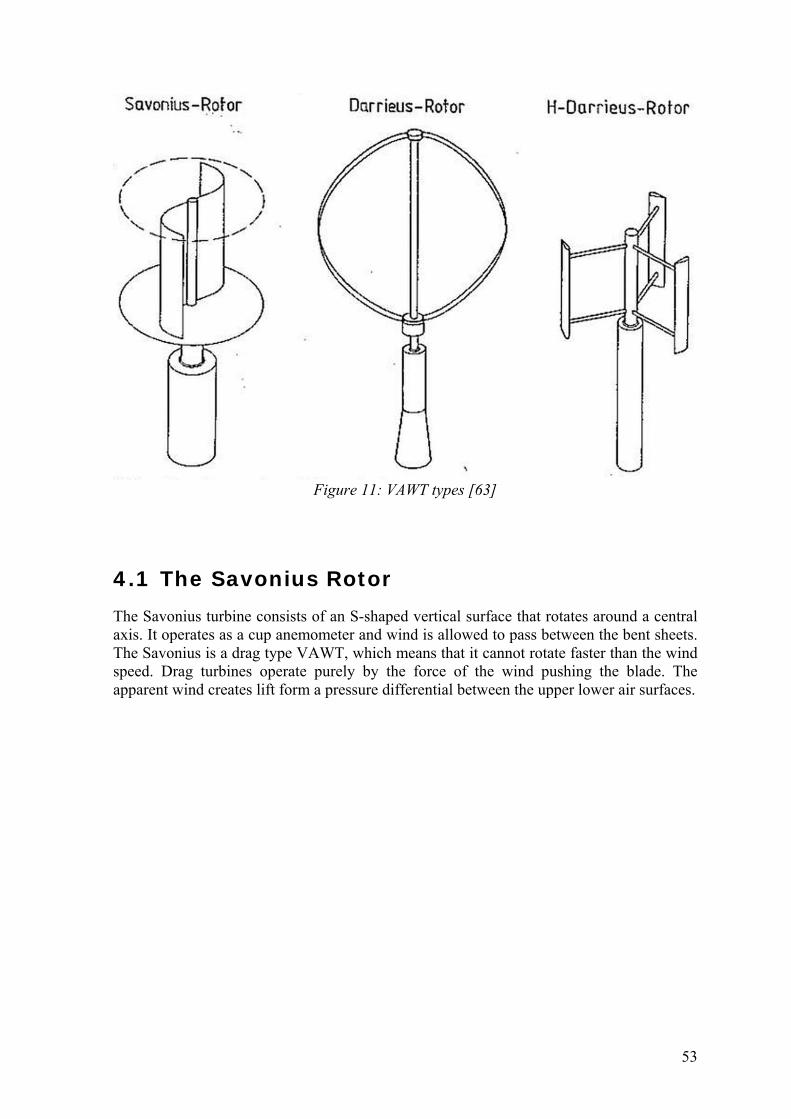
53
Figure 11: VAWT types [63]
4.1 The Savonius Rotor The Savonius turbine consists of an S-shaped vertical surface that rotates around a central axis. It operates as a cup anemometer and wind is allowed to pass between the bent sheets. The Savonius is a drag type VAWT, which means that it cannot rotate faster than the wind speed. Drag turbines operate purely by the force of the wind pushing the blade. The apparent wind creates lift form a pressure differential between the upper lower air surfaces.
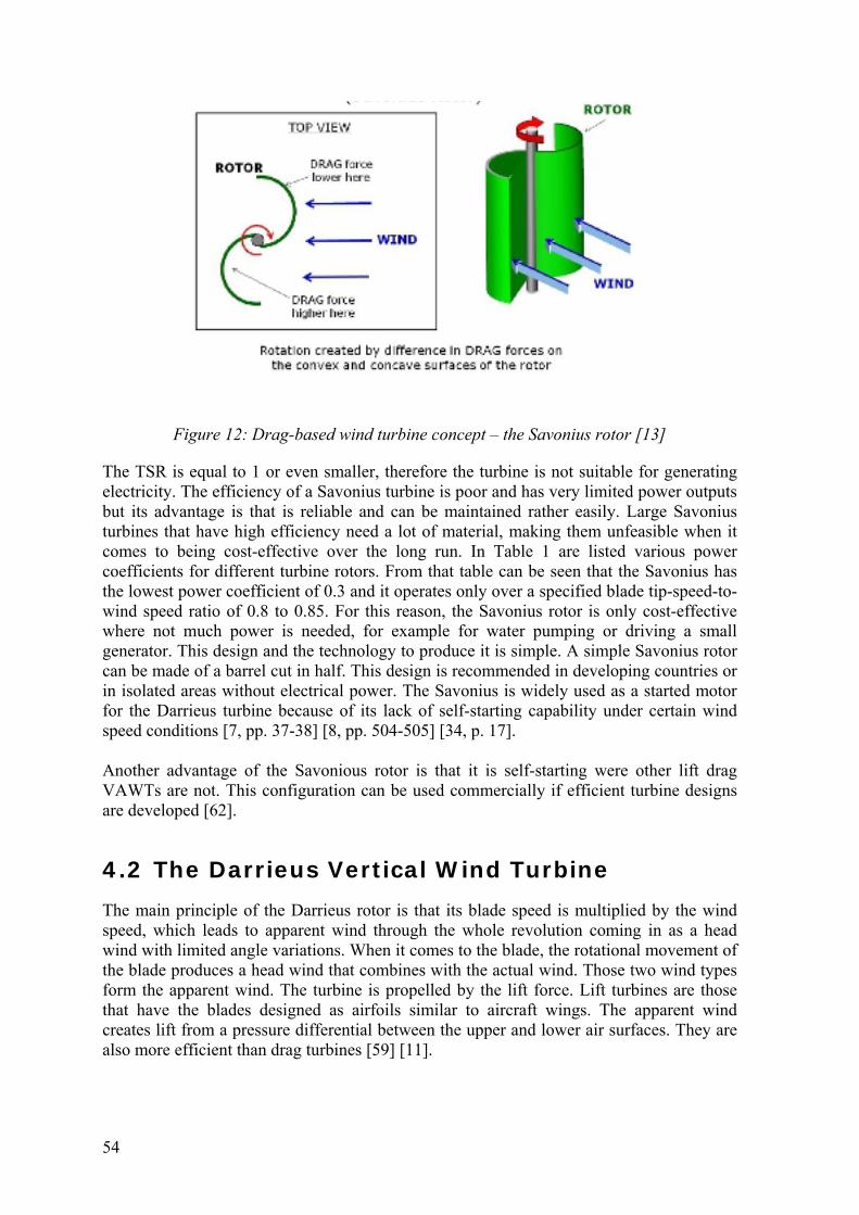
54
Figure 12: Drag-based wind turbine concept – the Savonius rotor [13]
The TSR is equal to 1 or even smaller, therefore the turbine is not suitable for generating electricity. The efficiency of a Savonius turbine is poor and has very limited power outputs but its advantage is that is reliable and can be maintained rather easily. Large Savonius turbines that have high efficiency need a lot of material, making them unfeasible when it comes to being cost-effective over the long run. In Table 1 are listed various power coefficients for different turbine rotors. From that table can be seen that the Savonius has the lowest power coefficient of 0.3 and it operates only over a specified blade tip-speed-to-wind speed ratio of 0.8 to 0.85. For this reason, the Savonius rotor is only cost-effective where not much power is needed, for example for water pumping or driving a small generator. This design and the technology to produce it is simple. A simple Savonius rotor can be made of a barrel cut in half. This design is recommended in developing countries or in isolated areas without electrical power. The Savonius is widely used as a started motor for the Darrieus turbine because of its lack of self-starting capability under certain wind speed conditions [7, pp. 37-38] [8, pp. 504-505] [34, p. 17]. Another advantage of the Savonious rotor is that it is self-starting were other lift drag VAWTs are not. This configuration can be used commercially if efficient turbine designs are developed [62].
4.2 The Darrieus Vertical Wind Turbine The main principle of the Darrieus rotor is that its blade speed is multiplied by the wind speed, which leads to apparent wind through the whole revolution coming in as a head wind with limited angle variations. When it comes to the blade, the rotational movement of the blade produces a head wind that combines with the actual wind. Those two wind types form the apparent wind. The turbine is propelled by the lift force. Lift turbines are those that have the blades designed as airfoils similar to aircraft wings. The apparent wind creates lift from a pressure differential between the upper and lower air surfaces. They are also more efficient than drag turbines [59] [11].
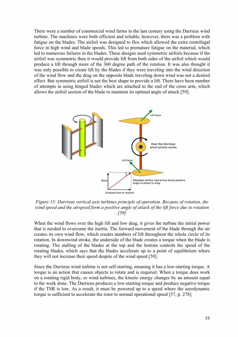
55
There were a number of commercial wind farms in the last century using the Darrieus wind turbine. The machines were both efficient and reliable, however, there was a problem with fatigue on the blades. The airfoil was designed to flex which allowed the extra centrifugal force in high wind and blade speeds. This led to premature fatigue on the material, which led to numerous failures in the blades. These designs used symmetric airfoils because if the airfoil was symmetric then it would provide lift from both sides of the airfoil which would produce a lift through more of the 360 degree path of the rotation. It was also thought it was only possible to create lift by the blades if they were traveling into the wind direction of the wind flow and the drag on the opposite blade traveling down wind was not a desired effect. But symmetric airfoil is not the best shape to provide a lift. There have been number of attempts in using hinged blades which are attached to the end of the cross arm, which allows the airfoil section of the blade to maintain its optimal angle of attack [59].
Figure 13: Darrieus vertical axis turbines principle of operation. Because of rotation, the wind speed and the airspeed form a positive angle of attack of the lift force due to rotation
[59]
When the wind flows over the high lift and low drag, it gives the turbine the initial power that is needed to overcome the inertia. The forward movement of the blade through the air creates its own wind flow, which creates numbers of lift throughout the whole circle of its rotation. In downwind stroke, the underside of the blade creates a torque when the blade is rotating. The stalling of the blades at the top and the bottom controls the speed of the rotating blades, which says that the blades accelerate up to a point of equilibrium where they will not increase their speed despite of the wind speed [59].
Since the Darrieus wind turbine is not self-starting, meaning it has a low-starting torque. A torque is an action that causes objects to rotate and is required. When a torque does work on a rotating rigid body, or wind turbines, the kinetic energy changes by an amount equal to the work done. The Darrieus produces a low-starting torque and produce negative torque if the TSR is low. As a result, it must be powered up to a speed where the aerodynamic torque is sufficient to accelerate the rotor to normal operational speed [57, p. 278].
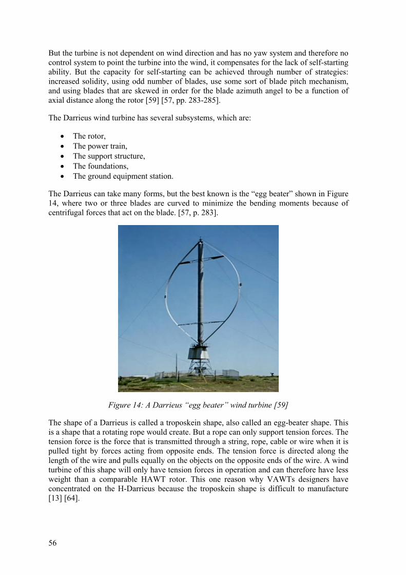
56
But the turbine is not dependent on wind direction and has no yaw system and therefore no control system to point the turbine into the wind, it compensates for the lack of self-starting ability. But the capacity for self-starting can be achieved through number of strategies: increased solidity, using odd number of blades, use some sort of blade pitch mechanism, and using blades that are skewed in order for the blade azimuth angel to be a function of axial distance along the rotor [59] [57, pp. 283-285].
The Darrieus wind turbine has several subsystems, which are:
The rotor, The power train, The support structure, The foundations, The ground equipment station.
The Darrieus can take many forms, but the best known is the “egg beater” shown in Figure 14, where two or three blades are curved to minimize the bending moments because of centrifugal forces that act on the blade. [57, p. 283].
Figure 14: A Darrieus “egg beater” wind turbine [59]
The shape of a Darrieus is called a troposkein shape, also called an egg-beater shape. This is a shape that a rotating rope would create. But a rope can only support tension forces. The tension force is the force that is transmitted through a string, rope, cable or wire when it is pulled tight by forces acting from opposite ends. The tension force is directed along the length of the wire and pulls equally on the objects on the opposite ends of the wire. A wind turbine of this shape will only have tension forces in operation and can therefore have less weight than a comparable HAWT rotor. This one reason why VAWTs designers have concentrated on the H-Darrieus because the troposkein shape is difficult to manufacture [13] [64].
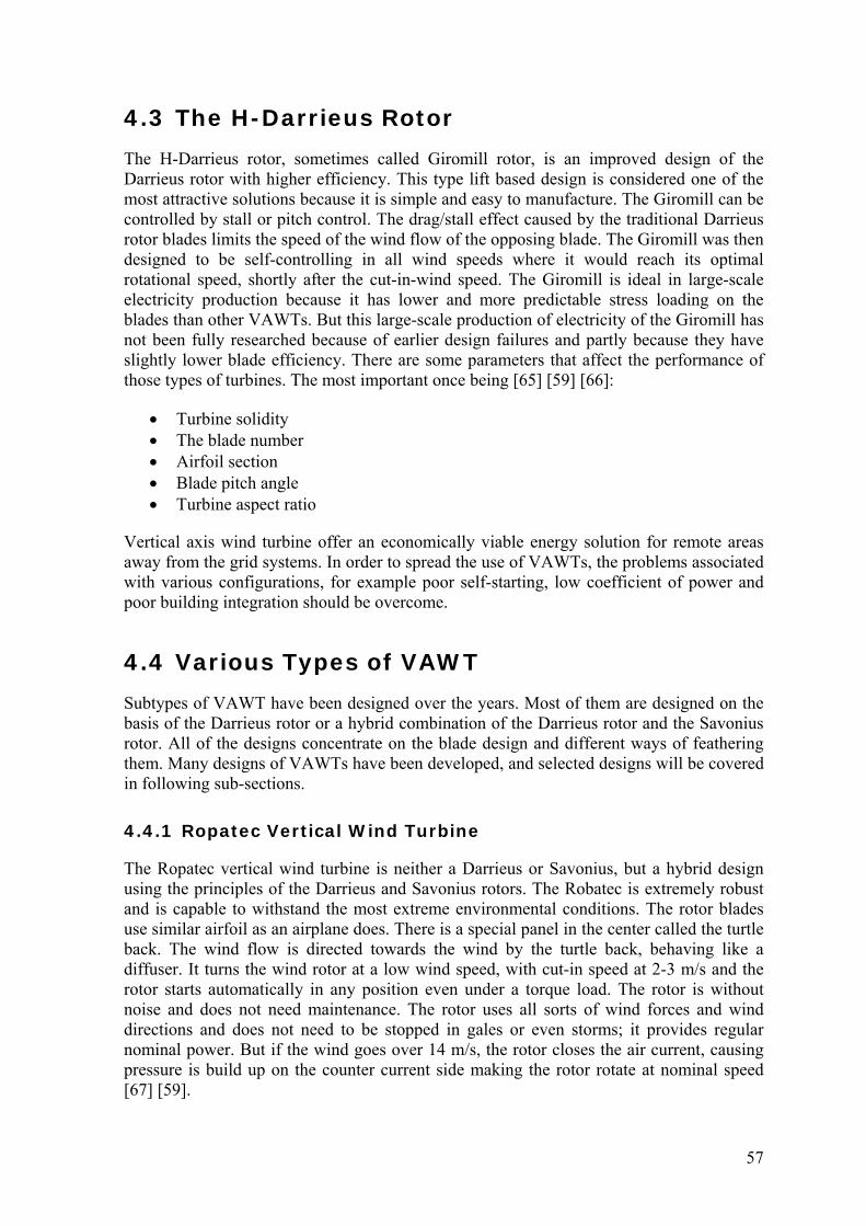
57
4.3 The H-Darrieus Rotor The H-Darrieus rotor, sometimes called Giromill rotor, is an improved design of the Darrieus rotor with higher efficiency. This type lift based design is considered one of the most attractive solutions because it is simple and easy to manufacture. The Giromill can be controlled by stall or pitch control. The drag/stall effect caused by the traditional Darrieus rotor blades limits the speed of the wind flow of the opposing blade. The Giromill was then designed to be self-controlling in all wind speeds where it would reach its optimal rotational speed, shortly after the cut-in-wind speed. The Giromill is ideal in large-scale electricity production because it has lower and more predictable stress loading on the blades than other VAWTs. But this large-scale production of electricity of the Giromill has not been fully researched because of earlier design failures and partly because they have slightly lower blade efficiency. There are some parameters that affect the performance of those types of turbines. The most important once being [65] [59] [66]:
Turbine solidity The blade number Airfoil section Blade pitch angle Turbine aspect ratio
Vertical axis wind turbine offer an economically viable energy solution for remote areas away from the grid systems. In order to spread the use of VAWTs, the problems associated with various configurations, for example poor self-starting, low coefficient of power and poor building integration should be overcome.
4.4 Various Types of VAWT Subtypes of VAWT have been designed over the years. Most of them are designed on the basis of the Darrieus rotor or a hybrid combination of the Darrieus rotor and the Savonius rotor. All of the designs concentrate on the blade design and different ways of feathering them. Many designs of VAWTs have been developed, and selected designs will be covered in following sub-sections.
4.4.1 Ropatec Vertical Wind Turbine
The Ropatec vertical wind turbine is neither a Darrieus or Savonius, but a hybrid design using the principles of the Darrieus and Savonius rotors. The Robatec is extremely robust and is capable to withstand the most extreme environmental conditions. The rotor blades use similar airfoil as an airplane does. There is a special panel in the center called the turtle back. The wind flow is directed towards the wind by the turtle back, behaving like a diffuser. It turns the wind rotor at a low wind speed, with cut-in speed at 2-3 m/s and the rotor starts automatically in any position even under a torque load. The rotor is without noise and does not need maintenance. The rotor uses all sorts of wind forces and wind directions and does not need to be stopped in gales or even storms; it provides regular nominal power. But if the wind goes over 14 m/s, the rotor closes the air current, causing pressure is build up on the counter current side making the rotor rotate at nominal speed [67] [59].

58
Regardless of the conditions in the area, the rotor should be installed at a height of 2.80 m to 20 m above the ground and it is recommended that the supporting structure is made of ferro-concrete/reinforced structure [67].
The rotor consists of [59] [67]:
A turbine A shaft with an integrated generator An intelligent charge regulator
The axis of the Ropatec is the central pole and has the generator bolted at the top of the pole. Both the axis and generator are in the assembly of the rotor and the generator is bolted in the inner tube, so when the rotor turns, the generator also turns [59] [67].
This design is reliable and is best suited where there is no grid network, e.g. refuges, maintain huts, isolated farms, television- and radio stations. It is also well suited for direct drive such as water pumps, mills, compressors etc. due to its high rotation starting point [67].
Figure 15: An example of a Ropatec wind turbine
A detailed table of the standard equipment of the Ropatec wind turbine can been seen in the Appendix, Table 7.
4.4.2 Eurowind Wind Turbine Design
This H-Darrieus design allows the turbine to be attached to buildings, for example chimneys or other tall buildings without disturbing their normal use. It is also widely applied for urban, schools, supermarkets, home and low noise area [59].
The airfoil of the blades is asymmetrical and are selected with high lift and low drag characteristics in mind. The blades are then attached to supporting cross arms at a critical angle to maximize the performance of the turbine. The edges of the blades are parallel and

59
are not twisted. Because the airfoil is simple, the blades are produced mechanically in sections by extrusion [59].
In the Eurowind turbine, there is a slow speed alternator, so there is no need for separate generator sets, gearboxes or clutches.
There are some characteristics that the Eurowind turbine has, including [59]:
It is self-starting and helped by the increased blade configuration solidity and torque
By using three blades or more, it eliminates the risk blades to reach equilibrium during start-up rotation
If 2 or more blades are being used, reduces cyclic loading, power pulsation and fluctuation
Low noise level because of lower blade rotational speed Can utilize wind from any direction, therefore no yaw system needed Easy access of all components of the turbine There are no gearboxes because there is only one moving part, but there is a direct
drive and a permanent magnet generator The lifetime is around 20 years No gearbox Can both be used off-grid and on-grid
There are currently 5 different ranges of rated power, the range being 1.3 kW up to 30 kW. In the Appendix, a technical data can been seen in Table 8 [68].
Figure 16: Eurowind wind turbine [69]
4.4.3 Venturi “Energy Ball” Wind Turbine
The Energy Ball's design constricts the wind, thereby causing the pressure to drop inside the ball. This pulls in air flowing around the ball and helps turn the rotor blades. Because of this, the Venturi uses more of the wind and is therefore 40 percent more efficient than
60
propeller-style turbines of the same diameter. The Venturi is self-starting with a cut-in speed at 2 m/s and no cut-out speed [59].
Both ends of the rotor blades are attached to the hub. When the rotor is rotating, it creates a spherical surface. In the sphere, a low-pressure area is created attracting the air in front of the rotor towards the sphere. When the rotor has absorbed the wind energy from the air, the energy poor air is swung outwards through the Venturi planes and carried away by the surrounding airflow. The air surrounding the rotor and flowing through the turbine can be utilized with more efficiency; more than in conventional wind turbines [59].
Because the blades are attached to the hub, the feet of the blade and the blade itself are only subjected to non-fluctuating tensile stress. The blades are barely affected by gusts or gyroscopic influences. In case of blade failure, the blades is attached to the turbine at the other end. The Venturi turbine is simple to manufacture and relatively cheap because the blades can be cut by laser from a plate [59].
The generator is integrated into the central hub of the turbine and the magnetic field is induced by permanent magnets. Because the generator dimensions are matched to the rotor characteristics, it eliminates the expensive and problem-prone gearboxes [59].
The special aerodynamic characteristics of the blades allow the turbine to experience higher wind speeds than other turbines, enabling the Venturi turbine to produce electricity at a low wind speed. The Technical University of Delft made a wind tunnel measurement, showing the Venturi turbine having a 40 percent more efficiency, instead of 59 percent in the Betz’s law [59]. A crucial fact for the urban location is that the turbine can produce power from gusts while other turbines use these gusts for their start-up [59].
When it comes to noise, the traditional wind turbines are noisy in operation, making them a less attractive solution in urban areas. The Venturi is virtually silent because it has no tips like the traditional wind turbines, which are the main generators of noise. There is also no gearbox and the number of blades reduces the rotation speed. The Venturi is grid connected [59].
Technical specifications are listed in Table 9, in the Appendix [68] [59].

61
Figure 17: “Energy ball” wind turbine [70]
4.4.4 Turby Wind Turbine
The original Darrieus had some negative factors. For example it suffered from violent vibrations, a high noise level and rather low efficiency, caused by the flow of air around the blades. The Turby turbine is an improved design of the old Darrieus turbine. The Turby turbine has 3 helical shaped blades made of composite located at a fixed distance from the shaft and it is not self-starting. It has low vibrations, low noise level and good efficiency [59] [71].
The wind pulls the blades around both sides of the turbine, both from the direction the wind is blowing and coming. The blades spread the torque evenly over the whole revolution and then the blades have an angle of attack, which is less than 20°. What this does is it prevents the destructive vibrations and noise from other turbines. The helical shape provides another advantage of the blades generating a torque from upward-angled airflow found in urban areas [59].
This turbine is specially designed for urban or build-up environments. It is therefore has a 2.5 kW generator, which is designed for high rooftops. The electricity can be fed straight into the power system of the building, saving on energy transport costs and losses. But the turbine has to be placed in the middle of the roof on a mast with a height of 5 meters or more. If it is placed near the edges, the power will be reduced by about 1/3. The turbine if most efficient when placed in the center with wind perpendicular to the turbine and when the turbine is exposed to all wind directions [71] [59].
The cut-in speed is 4 m/s and has a cut-out speed ad 14 m/s and shuts down at higher wind speeds. But the Turby is compact, mobile, low noise and vibration free [59].
Specification sheet for the Turby wind turbine are listed in Table 10, Table 11, Table 12, Table 13, and Table 14, in the Appendix [59] [71]:

62
Figure 18: Turby wind turbine [72]
4.4.5 QuietRevolution QR5 Wind Turbine
This on-grid turbine design works well in urban environments where wind speeds are low and there are frequent changes in wind direction. It is suitable for root-tops installation or open spaces along buildings. The turbine shuts down when the wind speed exceeds the cut-out at 16 m/s.
The turbine has a control system that uses gusty winds with a controller that predicts the wind conditions at the site from older wind conditions in order to improve the amount of energy generated. The control system determines if there is enough wind for operation, and if so, activates a spun up to operating conditions and enters lift mode, generating power from the wind. The turbine will self-maintain in a steady wind of 4.0-4.5 m/s, but brakes in winds of 12 m/s and shuts down when the wind goes over 16 m/s [59].
There is less noise from this design than from a similar rated HAWT because it has less tip speed and the helical shape of the blades result in a smooth operation, minimizing vibration and noise [59].
The technical specifications are listed in Table 15 in the Appendix [59].

63
Figure 19: QuietRevolution QR5 wind turbine [73]
4.4.6 Windspire Wind Turbine
Like other VAWT, the Windspire wind turbine includes a rotor that operates in any wind direction, a generator that is built into the turbine, an integrated power inverter, turbine pole assembly and a wireless monitoring system [74].
The Windspire wind turbine was designed to endure unusually winds with at least 4.5 m/s average speed but works best where the average wind speed is 5.4 m/s. The rotor is a low speed Giromill (straight bladed Darrieus) and in operation the Windspire wind turbine operates quietly in areas with very high winds. The turbine can be used in urban, sub-urban and rural environments where there is access to a power grid [75].
The turbine has three sets of tall, narrow airfoils that catch the wind while spinning around a vertical axis. It is virtually silent in operation due to low TSR [59].
Technical specifications are listed in Table 16 in the Appendix

64
Figure 20: Windspire wind turbine [76]
Chapter four covered the main categories of the vertical axis wind turbines: Saviouns-, Darrieus- and the H-Darrieus rotors. The Savonius rotor has a low efficiency but it is reliable and easy in maintenance. Making the Savonius a high efficiency wind turbine is expensive because of large amount of material needed. But it is self-starting were other VAWTs are not. The Darrieus rotor is not self-starting and needs external force to start the turbine. But a great advantage is the dependency from wind direction and therefore has no yaw system. H-Darrieus is an improved design of the Darrieus rotor and considered the most attractive solutions because it is simple and easy to manufacture. It is ideal for large-scale electricity production because it has lower and more predictable stress loading on the blades.
The chapter also selected sub-types of the VAWTs. The Ropatec, Eurowind, Venturi, Turby, QR5, and the Windspire.
In the next chapter, the design process will be presented with a special emphasis on the wind turbine layouts.

65
5 Design of HAWT and VAWT When designing a Wind turbine, many considerations must be kept in mind, both general and very specific. The design process involves a large number of mechanical and electrical components that are used to convert wind power into electrical power. This process is influenced by a number of constrains but the most fundamental ones involve the potential economic viability of the design. The turbine should be able to produce electricity at a lower cost than its competitors, competitors being fuel, gas and coals, and other renewables. There are many factors that influence the cost of the energy. The primary being cost of the turbine itself and the annual energy productivity. Other costs are installation, operation and maintenance. Those factors influence the design of the turbine and must be kept in mind in the design process. The productivity is controlled by both the wind resource and the design. The resource cannot be controlled, but the designer must consider how it is best utilized. The turbine must be strong enough to survive extreme events, be reliable with minimum repairs and the weight of the components must be as low as possible to minimize costs. Those components experience high and variable stresses. The fundamental consideration of the designer should be to balance the cost of the wind turbine and the lifetime of the turbine when it comes to fatigue [5, pp. 247-248].
5.1 Design Procedure Some approaches can be made when designing a wind turbine and many issues have to be considered. This section outlines the steps in one approach. The key design steps are as follows [5, p. 248]:
1. Determine application The first step when designing a wind turbine is to determine the application. Wind turbines that are being used for large-scale power production have a different design than those used in more remote areas. Major factor in choosing the size of the turbine is the application or the usage. The type of generator, method of control, and how it is to be installed and operated are also major factors [5, p. 249].
2. Review previous experience Step two is reviewing previous experience, mainly when it comes to building a turbine for similar applications. Older turbines give useful information in how they were built and tested. Helping the designer narrow the options. General previous experiences have shown that the, maintenance, and service to the turbine must be safe and straightforward [5, p. 249].
3. Select a layout Step 3 is the main focus in chapter 5, and will be further outlined in section 5.2
4. Preliminary loads estimate It is vital to estimate the loads the turbine must be able to withstand, which is done early in the design process. Those estimated loads influence individual components
66
in the turbine. At this stage it is important to keep in mind all the loads that the turbine will be able to withstand in operation [5, p. 250].
5. Develop tentative design A preliminary design can be developed after the layouts have been chosen and loads have been estimated. The design consist of number of subsystems which are [5, p. 250]:
Rotor (blades, hub, aerodynamic control surfaces) Drive train (shafts, couplings, gearbox, mechanical brakes, generator) Nacelle and main frame Yaw system Tower, foundation and erection
6. Predict performance
It is also important to predict the performance of the turbine done by using the power curve. Even though the rotor of the turbine is the main contributor in performance, the type of generator, efficiency of the drive chain, the method of operation (constant speed and variable speed), and the choices made in the design of the control system are important [5, p. 250].
7. Evaluate design The turbine must be able to withstand any expected loadings – this is where the preliminary design is evaluated. The turbine must be able to withstand any loadings that can take place in normal operation. The turbine must also be able to withstand extreme loads that can occur in abnormal circumstances. Various stress levels will generate fatigue damage occurring in a periodic manner proportional to rotor speed, a random manner, or because of transient loads. The loads that the turbine must be able to withstand are as follows [5, p. 251]:
Static loads (not associated with rotation) Steady loads (associated with rotation, for example centrifugal force) Cyclic loads (due to wind shear, blade weight, yaw motion) Impulsive (short duration loads, such as blades passing through tower
shadow) Stochastic loads (due to turbulence) Transient loads (due to starting and stopping) Resonance induced-loads (due to excitations near the natural frequency of the
structure)
The loads most important to keep in mind are those that affect the rotor, especially at the blade roots. But any load that effect the rotor distributes through the rest of the structure, so the loadings of each component must be evaluated [5, p. 251].
8. Estimate costs and cost of energy How much the turbine produces and the cost of the turbine itself are key factors in the cost of energy. It is therefore important to evaluate the cost of the turbine when it comes to the prototype stage and production. The components of the turbine can be both standard from the manufacturer custom made for the project in question,

67
custom-made usually being more expensive in the prototype. But if there is a mass production of the component in question, the price can drop to the same level as the standard item of similar material, complexity and size [5, p. 251].
9. Refine design The next step is to refine the design according to the previously mentioned factors and analyze in a similar way to the processes summarized above. This refined design is used in building a prototype [5, p. 252].
10. Build a prototype A prototype should be built after the prototype design is completed. The prototype verifies the assumptions in the design, tests new concepts and make sure the turbine can operate as expected [5, p. 251].
11. Test the prototype After the prototype has been built and installed, tests are done to verify the performance predictions where the power is measured and a power curve is developed. The estimated strain is applied to critical components and the actual loads are measured and compared to predicted values [5, p. 252].
12. Design production machine The production of the machine is the final step in the design process. The final design should be as close to the prototype as possible. However, improvements from the prototype and lower cost for mass production are acceptable [5, p. 252].
5.2 Wind Turbine Layouts There are many layouts that can be chosen in the design of a wind turbine and most of them relate to the rotor. This chapter provides an overview of factors that must be considered. The most important considerations are listed below [5, p. 249]:
Rotor axis orientation: horizontal or vertical Power control: stall, variable pitch, controllable aerodynamic surfaces and yaw
control Rotor position: upwind, downwind, Darrieus, Savanius, H-Darrieus ect Yaw control: driven yaw, free yaw or fixed yaw Rotor speed: constant or variable Design TSR and solidity Type of hub: rigid, teetering or hinged blades Number of blades Tower structure
5.2.1 Rotor Axis Orientation: Horizontal or Vertical
The orientation of the rotor is one of the most fundamental decisions when designing a wind turbine. The most common rotor type is horizontal, which is referred to as a horizontal axis wind turbine. The main advantages is high generating capacity, improved efficiency, variable pitch blade capacity, and tall tower to capture large amount of wind

68
energy. There are also disadvantages such as consistent noise, killing of birds, interference with radio, TV transmission and radar, land use, maintenance worker hazards and visual impacts [5, pp. 253-254].
One of the major advantages of a vertical axis rotor is it can accept wind from any direction and therefore no need for a yaw system. Also, the blades can have a constant chord and no twist, which makes the blades relatively cheap to manufacture. Finally, the gearbox, generator and brake are located at the base of the tower, making maintenance easier and cheaper [5, pp. 253-254]. But on the other hand, there are disadvantages. For example tendency to stall under gusty wind conditions, blade fatigue sensitivity due to wide variation in applied forces during each rotation. They also have low starting torque, dynamic stability problems and low installation height limiting operation to lower wind speed environments.
In Table 4, some configurations of VAWT and HAWT are summarized [62]:
Table 4: Some configurations of VAWT and HAWT
VAWT HAWTTowersway Small Large
Yawmechanism No Yes Overallformation Simple Complex Generallocation On ground Not on ground
Heightfromground Small Large Blade’soperationspace Small Large
Noiseproduced Less Relatively low Winddirection Independent Dependent
Obstructionforbirds Less High
5.2.2 Power Control: Stall, Variable Pitch, Controllable Aerodynamic Surfaces and Yaw Control
There are mainly three control systems for a wind turbine; stall control, pitch control, and yaw control.
The stall control system reduces aerodynamic lift at high angles of attack which reduce torque at high wind speeds. In order for the stall to function, the speed of the rotor has be controlled separately with an induction generator. The generator is then connected to the grid. In stall control systems, the maximum power is reached at a high wind speed. The drive train is designed to adjust the torques when this happens, even though such winds are infrequent. Stall-controlled turbines always have a separate braking system in order to shut down the turbine under all circumstances. The vertical axis H-Darrieus wind turbine uses this kind of control system. The Darrieus rotors are stall-controlled, because pitch-change mechanisms have not been found to be cost-effective for this type of rotors [5, p. 254] [59] [58, p. 64].
Variable pitch control systems are used when the turbine has blades rotating about their long axis, which changes the pitch angle of the blades. Changing the pitch also changes the angle of attack of the relative wind and the produced amount of torque. There are more control options when it comes to variable pitch control, but the hub is more complicated

69
because pitch bearings and some form of actuation system need to placed. The vertical axis H-Darrieus wind turbine and HAWT use pitch control systems [5, p. 254] [59].
There are some turbines that use the aerodynamic surface of the blade to control or modify power. The aerodynamic surface is almost always used as a braking system for the turbine. Sometimes the surface provides a fine-tuning effect when ailerons are being used [5, p. 254].
A yaw control system is another option used in wind turbine. When the rotor is turned away from the wind it is reducing power. The yaw control system turns the rotor in the right direction, or facing the wind. Yaw control systems are only used in HAWT because VAWTs are dependent to wind direction and therefore do not need for this control system [5, p. 254] [59].
5.2.3 Rotor Position: Upwind or Downwind, Darrieus, Savanius or H-Darrieus
When it comes to HAWT, the turbine can either be upwind or downwind of the tower.
A turbine with a downwind rotor can have a free yaw, which means that it adjusts itself automatically. This is much a simpler procedure than an active yaw, but it does not adjust itself under abrupt or sudden changes in wind direction. It is also easier to take advantage of the centrifugal forces in order to reduce the blade root flap bending moments. The blades in a downwind rotor are usually coned downwind, and because of thrust, the centrifugal moments work against other moments. Also, in the downwind direction, the tower produces a wake5 where the blades have to pass through the wake in every revolution. Periodic loads occur because of this wake, causing fatigue damage in the blades leading to uneven electrical production, and causing more noise than in upwind rotors. It is possible to reduce the effect of a wake by using a tower design that would create less obstacle to the flow [5, pp. 6, 254-255].
Upwind- and downwind are more suited for high-capacity HAWT. But most modern wind turbines use upwind design configuration. The advantage of downwind rotor is the automatic adjustments to wind direction, but not possible under abrupt or sudden changes in wind direction. This operational deficiency can be overcome with a three-bladed upwind rotor design configuration. For this reason, upwind rotor design dominate the market, where an active yaw system is used. The tower must, however, be able to resist the torsional loads coming from the yaw system
When it comes to VAWT, the rotor can be Savonius, Darrieus or H-Darrieus, since all of these rotors can accept wind from any direction.
The Savonius rotor has a poor efficiency with limited power outputs but it is reliable and can be maintained rather easily. On the other hand, it needs a lot of material making them unfeasible when it comes to being cost-effective. As stated before, the Savonius rotor has the lowest power coefficient of 0.3 and it operates only over a specified blade tip-speed-to-
5 Also called tower shadow effect, which is the wake created by airflow around a tower [5, p. 6]

70
wind speed ratio of 0.8 to 0.85. The Savonius rotor is therefore only useful and economic where not much power is needed.
The Darrieus rotor is not self-starting and it needs an outside force in order to start the turbine. The turbine is not dependent on wind direction and therefore needs no control system to point the turbine into the wind, compensating the lack of self-starting ability.
The H-Darrieus rotor is an improved design of the Darrieus rotor. It can be controlled by stall or pitch control. The H-Darrieus rotor was designed to be self-controlling in all wind speeds, where it would reach its optimal rotational speed shortly after the cut-in-wind speed. The H-Darrieus is an ideal rotor in large-scale electricity production because it has lower and more predictable stress loading on the blades than other VAWTs. The most important parameters that affect the performance are, turbine solidity, the blade number, airfoil section, blade pitch angle, and turbine aspect ratio.
5.2.4 Yaw Control: Driven Yaw, Free Yaw or Fixed Yaw
Wind direction changes and HAWTs must therefore have some sort of control system to point the turbine in the right direction. For the control system to work, the turbine has to accurately measure the wind to maintain dynamic stability and reliable operation under all sorts of wind environments and turbulence. Anemometers gather this information.
The downwind turbines have a free yaw, meaning it does not need a yaw drive mechanism because the rotor aligns itself with the wind direction. The turbine follows the wind like a weather vane. For the free yaw to work effectively, the blades are coned a few degrees in the downwind direction. The downwind turbines cannot provide the needed dynamic stability or reliable operation and therefore less common than upwind rotor designs.
The upwind turbines have some kind of active yaw control. The active yaw control includes a yaw motor, gears and brakes to keep the turbine stable when it is in the right position according to wind direction. The yaw system causes an extra torsional load on the tower which it has to be able to endure [5, p. 255].
The VAWTs do not have a yaw control system because they are not dependent on wind direction. This is one of the biggest advantages of the VAWTs because the yaw system is an expensive factor in the wind turbine design, construction and maintenance.
5.2.5 Rotor Speed: Constant or Variable
Most turbines operate at a constant rotational speed, which is determined by the generator and the gearbox. But sometimes the rotational speed of the rotor is allowed to vary. The design can be affected by the choice of constant/fixed or variable rotor speed. Almost all turbines that have variable rotor speed combine to power electronic converters to make sure that the resulting power is in the correct form. The converters allow some flexibility in the choice of a generator. If a low speed generator is used, it can eliminate the need for a gearbox and have a great effect on the layout of the turbine as a whole. When designing a wind turbine, the possible effects of electrical noise because of the power electronics in variable speed turbine has to be taken into account [5, p. 255].

71
5.2.6 Design TSR and Solidity
The tip speed ratio (TSR) is the most critical design issue in choosing between a HAWT and a VAWT. The TSR is the relationship between the velocity of the rotor blade and the relative wind speed [7, p. 45].
The TSR is where the power coefficient is at maximum. This value has a great effect on the design of the turbine. When it comes to the TSR and the solidity of the rotor6 there is a direct relation because a high-speed rotor will have less blade area than the rotor of a slower turbine. The chord, thickness and number of blades will decrease as the solidity decreases. Advantages are when the number of blades are fewer, and weight decreases, the cost will reduce. Also, higher rotational speeds imply lower torques for a given power level resulting in lighter balance of the drive train. Disadvantages of high TSR include being noisier than slower rotors [5, p. 256].
When choosing a TSR efficiency, torque, mechanical stress, aerodynamics and noise must be considered. As the number of blades increase, the lower the TSR.
High TSR that range from 2 to 8, regardless of their type, are required to reach optimum performance when it comes to reliability, dynamic stability under various violent weather conditions, power coefficient and power output [7, p. xxi].
The power coefficient is also an important performance parameter when it comes to VAWTs which is strictly a function of the tip speed ratio. Table 5 shows the calculated values of power coefficient for a VAWT at an optimum as a function of tip speed ratio. The table shows the TSR is at optimum at 5 [7, p. 45].
Table 5: Values of power coefficients at optimum drag-to-lift ratios for VAWTs [7, p. 45]
TipSpeedRatio PowerCoefficient
2 0.247
3 0.347
4 0.418
5 0.435
6 0.416
7 0.335
8 0.168
6 The area of the blades relative to the swept area of the rotor

72
5.2.7 Rigidity, Flexible or Stiff
When the turbine has a low TSR, higher solidities tend to be relatively stiff but lighter turbines are more flexible. Flexibility is better when it comes to relieving stress but the movements of the blades are not as predictable. When the tower is unloaded, a flexible blade in an upwind turbine may be far away from the tower, but the blade in high winds can hit the tower. The natural frequencies of blades and towers can be close to the operational speed of the wind turbine or a flutter motion can take place in flexible blades, which should be avoided because it leads to unstable operation [5, p. 256].
5.2.8 Type of Hub: Rigid, Teetering Blades or Gimballed
The design of the hub is another important factor when it comes to overall layout of a HAWT. The hub can be rigid, teetering or hinged. The two general types of rotors are rigid or teetered. Most three bladed turbines have rigid rotors, where each blade is bolted to the hub and the hub is rigidly attached to the turbine shaft. In three-blade rotors, the cyclic loads on the turbine shaft are much smaller than the cyclic loads produced by two-bladed rotors with a rigid hub. That is, the blades cannot move in the flap- or edge-wise direction, and the blades transmit all of the dynamic loads directly to the shaft. A rigid rotor includes variable pitch blades. In a two-bladed turbine, the rotor is usually teetering. When the rotor is teetering, the hub is mounted on bearings, can teeter both back and forth, and in and out of the rotation plane. Here, the blades are rigidly connected to the hub and during teetering, one blade moves in upwind direction while other moves in downwind direction. A benefit of teetering rotors is the bending moments in the blades can be low during normal operation. The teeter motion is passive because it balances the air loads on the two blades by increasing the lift force by cycles, while decreasing others. Teetering also reduces the cyclic loads on the two-bladed rotor on the turbine shaft. Hinges are used on the hub in some two-bladed turbines. The hinges allow the blades to move in and out of the plane of rotation and are independent of each other. There is a design called the ‘gimballed turbine’ that uses a rigid hub, where the entire turbine is mounted on horizontal bearings. Those bearings help the turbine to tilt up or down from horizontal helping to relieve imbalances in aerodynamic forces [5, p. 256] [58, p. 53].
Or in other words, in high capacity wind turbines, the connection between the hub and the blades have to be rigid to assure mechanical integrity under different wind conditions. When the turbine has one or two blades, the blades can be flexible in the vertical plane if the right connections are being used. In cases of teetering hub, the two-bladed rotor can teeter a few degrees across the hub, which will decrease the loads on the HAWT, yielding higher dynamic stability of the whole system of the HAWT. When there is a severe dynamic imbalance, the turbine is threatened by the imbalance and danger of unsafe operation [7, pp. 93, 103].
The Darrieus rotor has an upper and a lower hub that is rigid, but all VAWTs have rigid hubs [77, p. 9] [58, p. 64].
5.2.9 Number of Blades
Most HAWTs have three blades, but there are some that have one or two. One of the pros of three-bladed HAWTs is that the polar moment of inertia is constant with respect to
73
yawing. This factor, and that it is not dependent on the azimuth, makes the operation smoother. The two-bladed rotor has a lower moment of inertia when the rotor has vertical blades. Rotors with more than three blades are not often used because, even though more blades lead to moments of inertia, there is extra cost. Also, the number of blades increases stress at the blade root of the rotor and when the number of blades is increased, the TSR decreases. One-bladed rotors can run at a relatively high TSR leading to lower cost but it there is need for a counterweight to balance the weight of the single blade [5, pp. 256-257]. The VAWT blades rotate on a rotational surface where the axis is at the right angle to the wind direction. The angle of attack is constantly changing when the turbine is rotating. One blade is moving on the downwind side of the other blade at the range of 180° to 360° of rotational angle, the wind speed decreases because the upwind blades are extracting energy from the wind in the area in question. In other words the power production is less in the downwind part of the rotation. Also, lift forces cause a production of torque when the blades are rotating in this way, but the breaking torque of the drag forces are much lower. A single rotor blade produce a mean positive torque in one revolution but there is a negative torque in some sections. In VAWT rotors can only produce a torque if there is a marginal/circumferential speed because they are usually not self-starting [78]. The number of blades for a VAWT depends on the solidity of the rotor, or when the solidity of the rotor decreases, the number of blades also decreases. But the utilization of wind decreases with an increase in blades [79].
5.2.10 Tower Structure
The purpose of the tower is to keep the turbine high enough in the air so the blade tips will not touch the ground. Also, the wind is both stronger and less turbulent higher from the ground so the higher the tower, the better. The height of the tower is chosen depends on the economic tradeoff when it comes to energy capture and increased cost as the tower is build higher.
When measuring the wind speed and turbulence, the height should be at least 2/3 of the hub that will be built. The uncertainty decreases if the measurement is performed higher. The period for the measurement should be at least one year [19].
Most towers are tubular structures. The main concern in the design is the tower stiffness, which has a direct effect on the natural frequency of the tower. When the tower is stiff, the fundamental natural frequency is higher than the blade passing frequency, or the rotational speed of the rotor times the number of blades. These towers are relatively insensitive to the motion of the turbine, but they are expensive because they are heavy. Soft towers have fundamental natural frequency that is lower than the blade passing frequency. Also, their natural frequency is below the rotor frequency and the blade passing frequency. They are less expensive than the stiffer towers because they are lighter. A careful analysis has to be made to ensure that motions in the rest of the turbine stimulate no resonances.
Other factors influencing the selection of a tower is how easily it can be erected and how it looks. If the turbine is erected by tilting it up, it is best to keep the tower as light as possible. When a crane is used, it must be able to handle the load of erecting the tower.

74
This must be considered in the design process. Tubular towers appear to be the best design in order to minimize the impact on birdlife [5, p. 257].
VAWT towers are much lower than HAWT towers because the speed of the rotor blades near the ground is relatively much lower. The ground clearance for safety is also less for the VAWT than the HAWT. For the height of the support stand to be increased depends on the trade-off between the marginal increase in the capture of energy and its increased cost. Average wind speed usually increases with height and the average wind power density of VAWT rotors is almost always lower than for HAWT rotors at the same site [58, p. 65].
One type of design process was covered in this chapter with emphasis on the turbine layout. The most important considerations were presented. There is the rotor axis orientation: horizontal or vertical. Power control: stall, variable pitch, controllable aerodynamic surface and yaw control. Rotor position: upwind, downwind, Darrieus, Savanius, H-Darrieus ect. Yaw control: driven yaw, free yaw or fixed yaw. Rotor speed: constant or variable. Design TSR and solidity. Type of hub: rigid, teetering or hinged. Number of blades. And finally, tower structure. In each sub-section, there was a comparison of HAWT and VAWT.
Next, there will be a presentation on the wind farm layouts.

75
6 Wind Farm Layouts Wind turbines are usually grouped together into a wind farm to produce electrical power in order to lower both installation and maintenance cost. However, grouping turbines together leads to a decrease in the power production because of the wake effect7, which leads to considerable power loss. Therefore it is desirable to minimize the wake effect in order to maximize the power output. The wind farm layout optimization problem, or WFLOP, is about finding the right position for the wind turbine within the wind farm so the power production can be maximized and the wake effect can be minimized. Today, this problem is solved by simple rules that lead to layouts where the turbines are in a straight line, identical rows and separated by an appropriate diameter. However, recent research papers have shown that irregular layouts produce more energy than regular grids [80] [81].
6.1 Construction of a Wind Farm The first step in building a wind farm is to find a windy site for the project to maximize profit. Sites are classified into 7 different wind power density classes where each class has different average-wind intervals and range of mean power density at a specified heights about the ground. Sites that are in class 4 or higher are considered profitable for wind energy production. Reasons for non-profit are usually high cost due to the site being far away from a power grid or unreachable for very long trucks. Class 3 areas are suitable for wind energy development using tall turbines (50 m hub height) [82, pp. 63-65] [80].
The second step would be to contact the landowners and inquire if they are interested in hosting wind turbines on their land. [80].
Third, the wind developer installs measurement towers to be able to access the wind distribution of all parts of the site in question. Those measurements are crucial for the project because they are used to find the optimal layout and assess profit expected of the wind farm [80].
In other words, when the land that can be used for the project is known and the wind distribution has been gathered, it is then possible to solve the WFLOP. Choosing the number of turbines or the model depends on various factors. For one, it is preferred to install a more powerful turbine than a less powerful one since both the cost of a turbine and the energy it produces is usually proportional to its nominal power. This leads to net profit produced by the turbine - also proportional to its nominal power.
This does not apply to the newest extremely powerful turbines with expensive spare parts and high maintenance cost. Because there are more powerful wind turbines being built, the cost of unused smaller turbines decreases. More manufactures are therefore offering discounts on small turbines in stock to reduce their inventory, but some wind farm
7 When the wind is extracted by the wind turbine, it produces a „wake“ of turbulence that scatters downwind, so that the wind speed and therefore the power that is extracted by the turbine is reduced [79].
76
designers/developers have their own inventory. In those cases, they may have extra turbines in stock that need to be used before they become outdated. Given these considerations, the existing works on the WFLOP assume the number and type of turbines have already been decided [80] [81].
Another method, not covered in the thesis, the unrestricted wind farm layout (UFWLO), simultaneously determines the optimum farm layout and the appropriate selection of turbines in respect of their rotor diameter, which maximizes the pet power generation. In a research paper by Chowdhury et al, showed that, an appropriate combination of different types of turbines might prove to be economically more beneficial than using identical wind turbines. The use of turbines with differing rotor diameters produced a remarkable increase in the total power generated by the farm. However, an appropriate consideration of the hub height, pertinent performance characteristics and a comprehensive cost model, is necessary to provide further insight in this direction [83].
6.2 Wake Effect, Power and Cost Modeling There are some factors that contribute to the optimization of the wind farm layout [80, pp. 23-24]
Cut-in speed Cut-out speed Nominal power Power curve Thrust coefficient curve8 Rotor diameter Hub and tower structure height Optimum parameters for rotor blades Spacing between turbine units Noise Visual effect
The turbine starts to rotate when the wind speed is greater than the cut-in speed and the turbine starts to generate power. The produced power increases until the wind speed reaches nominal speed. At that point, the control system adjusts the pitch angle of the blades making the produced power constant and equal to the nominal power. When the wind reaches the cut-out speed, the turbine shuts down so it will not damage the blades. Other important factors are the power curve and the thrust coefficient curve. The power curve reports the produced power and the thrust coefficient curve reports the value of the thrust coefficient between the cut-in speed and the cut-out speed. When the turbine is extracting energy from the wind, the turbine creates a cone and a turbulence of slower air behind it. This is the wake effect mentioned earlier. The wake effect has been studied in experiments aimed at identifying mathematical models that can describe this effect in
8 The thrust coefficient measures the ratio of the captured energy when the wind goes through the blades [79]
77
terms of wind reduction and turbulence intensity. Those models are only valid near the turbine that creates the wake, while others are only valid further away from the turbine. The Jensen model is most used when applying WFLOP because of its simplicity and precision in predicting wake loss [80] [84].
As stated earlier, when building a wind farm, a proper site has to be found. When the land being used for the wind farm is known and the distribution of the wind has been obtained, it is then possible to solve the WFLOP. The site, or the terrain, determines the optimal spacing between the turbines. Models for wake effect and the investment cost for the turbines are therefore needed.
WFLOP use the Jensen model to study the wake effect and the Mosetti model for cost, based on genetic algorithm in order to optimize the objective function, which is based on the power output or combination of both power output and cost [80] [81].
6.2.1 Wake Effect Modeling for HAWT
When the wake is being determined, the Jensen model is the most used tool in WFLOP. The Jensen model neglects the near field effects and the near wake is simplified. The axisymmetric wake with a defected wind velocity scatters linearly downstream with distance, where it encounters another turbine. In order to evaluate the defected wind velocity, Equation 17 is applied [81]:
1 2 ( 17 )
Where, v0 is velocity defect (m/s), a is axial induction factor, U is mean wind speed (m/s)
And,
11 2
( 18 )
Where, r0 is radius of the axisymmetric wake immediately after the rotor (m), and rr is rotor radius of the turbine (m).
The thrust coefficient CT, in Equation 20, is related to the axial induction factor a, by the following relation [81]:
1 12
( 19 )
And
4 1 ( 20 )
The entrainment constant is evaluated by [81]:

78
0.5
( 21 )
Where, z is hub height (m), and z0 is surface roughness (m).
At distance x downstream, the wind velocity can be determined in Equation 22, by [81]:
1
2
1
( 22 )
Where, u is wind velocity (m/s) in the wake, x is distance (m) downstream, and a is entrainment constant.
Another model, the Werle model, is an attempt to improve the Jensen model. Werle divided the wake into three different parts: the near wake, the intermediate wake, and the far wake. The Jensens model does not take into account the near wake region, but the Werle model does, where the velocity is slightly higher compared to the intermediate wake region. The following procedure is done in order to evaluate the wind speed and wake growth downstream of the turbine [85]: ≡ ⁄ ( 23 )
Where X is non-dimensional distance downstream of the turbine (m), and D is the turbine diameter (m). When the non-dimensional distance downstream the turbine X, is less than the location where the far wake model is coupled to the near wake Xm, or:
The wind velocity is
112
12
√1 4
( 24 )
And,
12
( 25 )
Where, Dw is the diameter of the velocity defect in the wake X. But when the non-dimensional distance downstream the turbine is greater than the location where the far wake model is couples to the near wake, or:

79
The wind velocity is according to Equation 26,
11
2 11
( 26 )
Where, um is velocity in the wake at Xm, and Xm the location where the far wake model is coupled to the near wake, is given by:
22 1
1
( 27 )
And, 1
2
( 28 )
Where Dm is the diameter (m) of the wake at Xm.
112
12
1 4
( 29 )
Where um is the velocity (m/s) in the wake at Xm.
6.2.2 Multiple Power and Cost Modeling for HAWT
Downstream of an HAWT array can face multiple wakes because several upstream turbines. Because of the mixed types of wakes in the array, the kinetic energy in the mixed wake is assumed to be equal to the sum of kinetic energy of wake deficits. According to Mosetti et al, this leads to the expression of the velocity of N turbines downstream the array [85, 80]:
1 1
( 30 )
In Equation 30, ū is the average velocity (m/s) affected by the turbines because of the wake deficit velocity of multiple turbines, which is given by ui, and ui, i = … N
23
13
. ( 31 )
According to the HAWT power curve in Mosetti et al, gives the expression for the power output in all the wind farm [86]:

80
0.3
( 32 )
Finally, the optimization of the wind farm is based on the objective function:
1
( 33 )
The objective function is the cost function for the optimization, a method based on the genetic algorithm (GA). GA keeps a population of solutions that evolves through combinations and selections. At each step, solutions are pared, and a new solution is found the components inherited from one or two parents [80].
6.2.3 Wake Effect Modeling for VAWT
It is assumed that the VAWT has a Darrieus rotor with an actuator disc, where the near field behind the wind turbine is neglected. According to Chen and Agarwal, the Jensen model can be modified for the VAWT. The wake effect is as follows [81]:
2 2 2 ( 34 )
Where, H is total blade length (m).
And,
1
21 ⁄
( 35 )
Where u is the wind velocity (m/s) in the wake.
6.2.4 Power and Cost Modeling for VAWT
In order to evaluate the power output of a VAWT, the following steps are executed [81]:
Equation 36, shows how the lift coefficient is executed:
, , ( 36 )
Where, Cl,α is lift curve slope of small angle of attack
,
18 ( 37 )
Equation 38 shows how the induction factor, α, is calculated
116 , ( 38 )

81
Where, B is number of blades, R is rotor radius (m), λ is TSR, and e = ulocal/U, where ulocal represents the velocity u in the wake of a single turbine, the velocity due to multiple wakes.
4 1
12 , ( 39 )
And,
12
2 ( 40 )
Where Ps is the power output from a single VAWT.
6.3 Some Algorithm Work on WFLOP There are some algorithm methods in how to optimize a wind turbine layouts in a wind farm.
The evolutive algorithm optimizes wind turbine layouts by using mainly two kinds of operators to generate individuals are used: the crossover operator and mutation operator. The crossover operator have two selected individuals, parents that generate new individuals, known as children. The method uses a “roulette wheel”, where individuals with the highest objective function are more likely to be selected. The mutation operator is used on one individual to generate another by changing one chromosomes randomly. When the population is at maximum, this operator leads to the creation of individuals out of this zone of local attraction. This way the algorithm can evolve towards the global maximum. After operation of crossover or mutation, valid solutions cannot be created. Then, regenerative algorithm goes through the individuals and removes the turbines that are wrongly located and reduces the number of generator to the imposed limit. But in genetic algorithm, a local optimization operator appears to be convenient to decrease the computational effort. Without changing the best individual, a local search operator has been applied to those individuals and also to randomly selected individuals. Every turbine is moved to each free positons of the farm by the local search operator, until the objective function (NPV) has been improved [87].
In this thesis, the Generic Algorithm will be covered.
6.3.1 Genetic Algorithm
In order to optimize the wind turbine layout, a so-called genetic algorithm, or GA, is used. GA is a class of stochastic optimization algorithms inspired by the biological evolution. The first step is to start with an initial generation, where a group of input vectors represent a possible solution to the problem. Each solution includes a set of information used to decide its fitness in order to achieve an optimum solution. A specific procedure is done continuously until an optimal is reached [85].

82
6.3.2 Layout Optimization Work
There is a rule of thumb that states that [80]:
“Turbines in wind parks are usually spaced somewhere between 5 and 9 rotor diameters apart in the prevailing wind direction, and between 3 and 5 diameters apart in the direction perpendicular to the prevailing winds.”
The problem is that this approach does not take under consideration all wind directions except the prevailing one, therefore it is less likely to lead to less favorable layouts. Also, it does not describe how to evaluate the produced power when the wind blows from a crosswind direction. As a result, the Jensen model does not hold because the distance between the turbines that produce a wake is too short. The GA approaches have a flaw because in the center of the cells is a predefined set of possible positions where a subset must be chosen as installation positions of the turbine. Because the turbines are spaced consecutively by a distance of several rotor diameters and it is not possible to choose a position in between, means better positions are even considered [80].
A way to solve this problem is to install a finer grid as long as proximity constrains are used to avoid undesirable solutions. Those constrains forbid the turbines to be installed too close to each other, or less than 3D apart. But GA is not able to embed constraints. By enforcing them by introducing a feasibility check in the objective function evaluation routine would slow the search significantly. However, introducing the proximity constrains have not been tried, and therefore the impacts are unknown [80].
Aytun and Norman were the first to address the limitation of a discrete space. They proposed a local search that iteratively considers the operation of adding, removing, or moving turbines trying to improve the objective function value. The adding part of the procedure randomly generates set of locations, where each turbine is considered as a potential position for new sets turbines. The removing part of the procedure tries to move each existing turbine by 4D along a set of predefined directions. Every time the add procedure is considered, new locations are generated randomly and evaluated, so turbines can possibly be placed in any position at the site. This solution does not consider a continuous solution space, but a discrete space where possible positions for the turbine are generated randomly during the search [80].
Rivas et al. did a similar work consisting of simulated annealing procedure where the same procedure of adding, removing and moving are performed. Simulated annealing is a neighborhood kind of search that accepts non-improving moves and as such, overcomes the limitation of the Aytun and Norman approach, which was purely local. Not only did Rivas et al. improve the Aytun and Norman method, but they also performed a relevant computational study to find the difference between the quality of solutions from their method and the quality of solutions from the earlier mentioned rule of thumb. They approached two set of problems, installing 106 3 MW turbines and 5 64 MW turbines in a predefined geographical site areas. In order to solve the two problems, Rivas et al. used the proposed method or the rule of thumb. They found that if the site area increases, then the efficiency of the wind farm also increases. By using their method, a higher quality of solutions was found for the problem of 64 turbines but not for the problem of 106 turbines. In other words, the possible improvement of their method over the rule of thumb is more obvious if the turbines are big and few [80].
83
Even though their method only holds this problem, it also has a general property that holds for any method. The layout selected impacts the quality of the solution only if a few turbines are installed. This is based on the property of multiple wake superimpositions. Which states “the total velocity deficit mostly depends on the closest turbine that generates a wake”. At least one wake can be expected to affect a turbine if many turbines are being installed regardless of their position. But if few turbines are being installed, it is possible that a turbine is not affect by a wake or just few of them. An example of this is if the turbines are aligned in one row perpendicular to the wind direction. If many turbines are installed, the layout optimization may reduce the average number of wakes that affect the turbine at the same time, but have little effect on the objective function value. In cases where the turbines are few, the layout optimization can prevent some of the turbines from being affected by a wake, but that will have a great impact on the objective function value. Further studies must be performed to validate this [80].
The work performed is a good starting point for further research or for more effective solutions. But those methods are considered unsatisfactory by the scientific community for number of reasons. None of the solution methods are able to assess the quality of the found solution. None of the existing work on the subject computes an upper bound on the generated power. The present algorithms find a possible good solution, but none of them can say how much it is from the optimal. The wind farm developer needs to know if it is profitable to spend more time on finding a better quality layout, so he or she can decide to invest in the particular project at the determined site. Second, the algorithms can only been used as guidance. A precise solution method would allow a global optimum or a higher upper bound. Only one scientist, Donovan, has tried to obtain this, where he formulated the WFLOP as an integer program. However in his model, the wake effect is forbidden because it is not accounted for in the model [80].
Because of the wake effect and wind speed, a consideration is needed on the type of landscape of the territory. The work that has been done always considers a flat area and assumes that the wind distribution is the same throughout the entire site. This can be realistic for offshore sites but not for onshore sites that are usually uneven and not uniform. Hills, rivers, forests, buildings etc. influence the wind distribution and behavior of wakes. So far, these elements have not been considered, but it is difficult to implement a routine taking these factors into account when evaluating the value of the objective function [80].
A decrease in wind speed is not the only negative factor of the wake effect. The air in the wake also becomes more turbulent, ultimately leading to blade damage and high maintenance cost. Previous methods do not take this into account, even though the problem of turbulence is common. However it cannot been described accurately and there is no method to measure the cost of turbulence [80].
6.4 Layout Approaches for HAWT Modern farms generally consists of horizontal-axis wind turbines. In HAWT farms, the turbines have to be spaced far apart. As stated earlier, the wake generated by one turbine can interfere aerodynamically with neighboring turbines, leading to wind energy entering the wind farm not being utilized to the fullest.
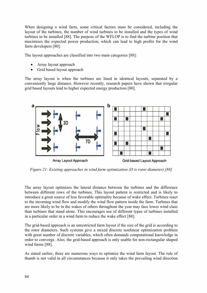
84
When designing a wind farm, some critical factors must be considered, including the layout of the turbines, the number of wind turbines to be installed and the types of wind turbines to be installed [88]. The purpose of the WFLOP is to find the turbine position that maximizes the expected power production, which can lead to high profits for the wind farm developers [80].
The layout approaches are classified into two main categories [88]:
Array layout approach Grid based layout approach
The array layout is when the turbines are lined in identical layouts, separated by a conveniently large distance. However recently, research papers have shown that irregular grid based layouts lead to higher expected energy production [80].
Figure 21: Existing approaches in wind farm optimization (D is rotor diameter) [88]
The array layout optimizes the lateral distance between the turbines and the difference between different rows of the turbines. This layout pattern is restricted and is likely to introduce a great source of less favorable optimality because of wake effect. Turbines react to the incoming wind flow and modify the wind flow pattern inside the farm. Turbines that are more likely to be in the wakes of others throughout the year may face lower wind class than turbines that stand alone. This encourages use of different types of turbines installed in a particular order in a wind farm to reduce the wake effect [88].
The grid-based approach is an unrestricted farm layout if the size of the grid is according to the rotor diameters. Such systems give a mixed discrete nonlinear optimization problem with great number of discrete variables, which often demands computational knowledge in order to converge. Also, the grid-based approach is only usable for non-rectangular shaped wind farms [88].
As stated earlier, there are numerous ways to optimize the wind farm layout. The rule of thumb is not valid in all circumstances because it only takes the prevailing wind direction

85
under consideration. Also, it does not hold when the wind blows from a crosswind direction because it does not describe how to evaluate the generated power. Different types of the GA approach in finding the optimal layout is therefore used.
6.5 Layout Approaches for VAWT The space between towers in HAWTs in operation must be extensive in order to avoid turbulence from nearby turbines. To catch more wind, HAWTs must be built taller and at higher places, leading to more cost and visual impacts. Wind turbine design has improved in recent years, but wind farms are still inefficient. Massive three-bladed wind turbines interfere with each other and by placing them too closely together produces wind blocks and vortices leading to inefficiency.
The advantage VAWTs have is they can be placed closely together [89]. By doing so, they can capture most of the energy of the blowing wind and wind energy above the wind turbines in the farm.
6.5.1 Small Vertical Axis Wind Turbines Arrays
When a wind passes and goes through a wind turbine, it creates a turbulence that buffers downstream turbines, which reduces their performance, power output and increases wear and tear. The VAWTs produce a wake that benefit other turbines in the area if they are positioned correctly. The wind that is moving around the turbine speeds up because the blades are in vertical position and the turbines downstream catch the wind and generate more power. It is easy to manufacture VAWTs that are small. Small turbines are 10 meters tall, generate around 3 – 5 kW and cost less because the generator is located at the ground, making maintenance easier. Also, they generate less or almost no noise and kill fewer birds than the large HAWTs. VAWTs are a good choice when it comes to military bases because they are lower and interfere less when it comes to helicopters and radars. The VAWTs are not as efficient as HAWTs because half of the time the blades are moving against the wind, instead of creating a lift needed to rotate the generator. Also, the blades catch the wind and then move against it, creating wear and tear to the turbine structure. The problem can be fixed by placing a shield that would act like a protection against the returning stroke [59].
6.5.2 Counter Rotating Turbines Arrays
John Darbi, Caltech professor of aeronautics and bioengineering, wrote an interesting paper describing a field test and findings [89]. Darbi discovered this solution by studying the movement of fish. He saw that VAWTs with blades resembling fins could work together with more efficiency in order to harness wind energy [90].
“School of fish swimming in the ocean have to content with vortices and disturbances caused by the other fish. Some species use less energy to move from point A to point B in groups than when they are by themselves, because they are able to use these vortices to enhance their swimming performance.” [89]
He and his colleagues found that by facing every turbine in the opposite direction of its neighbor increases the efficiency, perhaps of the opposing spins decreasing the drag on

86
each turbine, leading to a faster spin. The reason being that the opposing spins decrease the drag on each turbine allowing them to rotate faster [90].
By placing VAWTs in counter-rotating arrays can yield twice as much power per acre as a HAWT, and placing VAWTs close to each other leads to improved efficiency and performance compared to isolated VAWTs. The counter-rotation of adjacent VAWTs ensures that airflow induced by the turbines in the region is oriented in the same direction. Turbulence and energy distribution between the turbines take place because of horizontal wind shear, or the velocity gradient, is reduced by nearby turbines rotating in the same direction. The remaining wind energy between the turbines not scattered by turbulence can be extracted by the VAWTs further downwind. This process is most efficient for VAWTs that have a greater TSR than 2. This approach is different than other applications in harvesting wind energy. Instead of placing few large HAWTs, a larger number of VAWTs are implemented. The higher levels of turbulence near the ground, that occur both naturally and are induced by VAWT configurations, increase the vertical flux of kinetic energy delivered by the turbines [59] [90].
Figure 22: Array of counter-rotating VAWT [59]
Figure 23: Dabiri's test array of modified Windspires in Antelope Valley, northern Los Angeles County [59]
A big problem in wind farm layouts is the wake effect from neighboring wind turbines within the wind farm. The site, or the terrain, determines the optimal spacing between the turbines. Models for wake effect and the investment cost for the turbines are therefore needed. Most WFLOP use the Jensen model to study the wake effect and the Mosetti model for cost [80] [81]. There are some algorithms than can be used in optimizing a wind farm, but here the concentration is on GA, and on research on optimization layouts, based on the GA. Both layout for HAWT and VAWT were presented.
The next chapter is a presentation of a flow chart diagram. A user friendly diagram for the needs of a customer.

87
7 The Flow Chart Diagram This chapter is about how to choose the “right” turbine for a given situation from the customer’s need where the questions are not technical. The wind turbine manufacturers usually have standard turbines in stock for various situations. If needed, it is possible to custom make the turbine.
A software program would be helpful, but before writing the software, a flow chart diagram of the procedure needs to be generated. Flowcharts are used in analyzing, designing, documenting or managing a process or program in various fields. A flow chart is defined as a “diagram that describes a process or operation. It includes multiple steps, which the process “flows” through from start to finish. Common uses for flowcharts include developing business plans, defining troubleshooting steps, and designing mathematical algorithms. Some flowcharts may only include a few steps, while others can be highly complex, containing hundreds of possible outcomes” [91].
Flow charts help computer- or software programmers in early stages of programming before writing the code. The control flow in the program is showed in computer program flowcharts. The program flowcharts are often used to show an algorithm without writing the actual code in a simple way. But writing the code would be the next step.
7.1 The Flow Chart
7.1.1 The Customer’s need
In order to design any flow chart, the customer’s needs have to be defined. The flow chart should take into account limitations, wishes and requirements. The wind turbine can be used to perform specific tasks, like grinding grain, pumping water or generating electricity. In this flow chart, the customer needs to buy a wind turbine to generate electricity. Factors like cost are not included in this decision process, but it should be in an improved flow chart.
7.1.2 The Purpose of the Wind Turbine
This question gives the option between electricity generated for commercial usage and electricity generated for private usage. In this flow chart, the turbines for private usage are off-grid and the turbines for commercial usage are on-grid. In the flow chat, a hybrid system is also taken under consideration, which is used with a connection to a grid and other power resources.
7.1.3 Power Grid
Medium sized turbines can both be used in applications where a power grid is needed and where it is not, because they can be for private and commercial usage. Private usage would
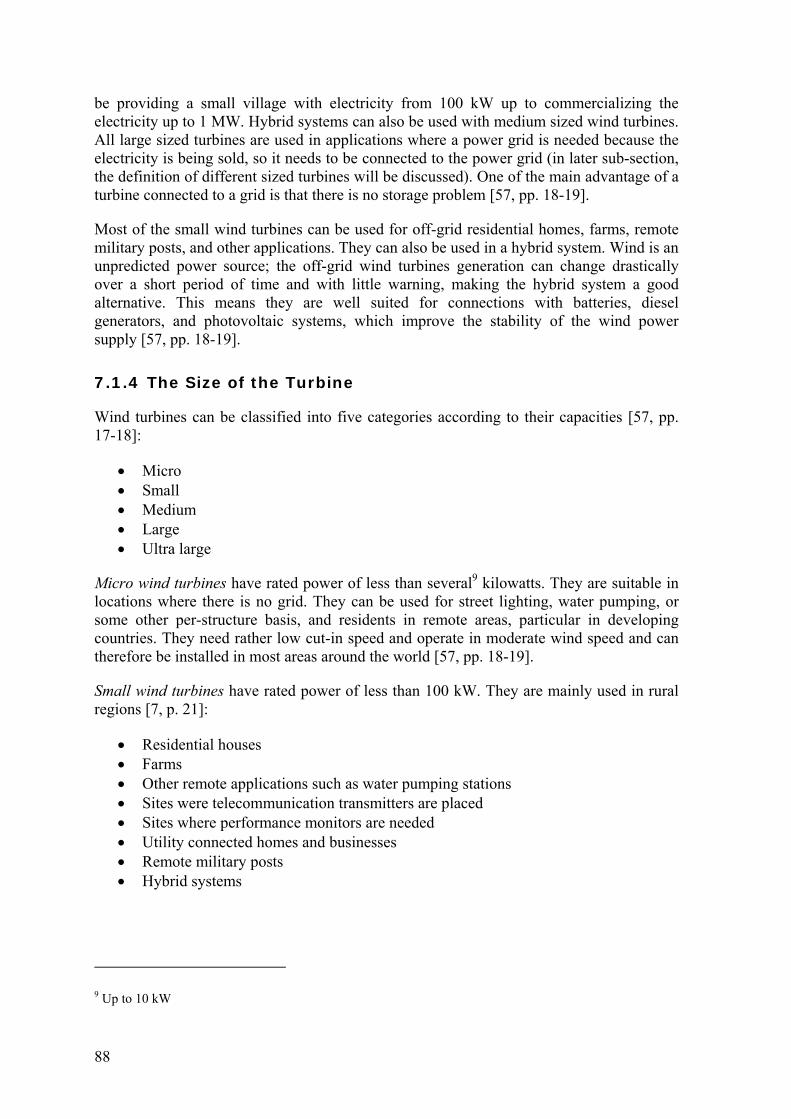
88
be providing a small village with electricity from 100 kW up to commercializing the electricity up to 1 MW. Hybrid systems can also be used with medium sized wind turbines. All large sized turbines are used in applications where a power grid is needed because the electricity is being sold, so it needs to be connected to the power grid (in later sub-section, the definition of different sized turbines will be discussed). One of the main advantage of a turbine connected to a grid is that there is no storage problem [57, pp. 18-19].
Most of the small wind turbines can be used for off-grid residential homes, farms, remote military posts, and other applications. They can also be used in a hybrid system. Wind is an unpredicted power source; the off-grid wind turbines generation can change drastically over a short period of time and with little warning, making the hybrid system a good alternative. This means they are well suited for connections with batteries, diesel generators, and photovoltaic systems, which improve the stability of the wind power supply [57, pp. 18-19].
7.1.4 The Size of the Turbine
Wind turbines can be classified into five categories according to their capacities [57, pp. 17-18]:
Micro Small Medium Large Ultra large
Micro wind turbines have rated power of less than several9 kilowatts. They are suitable in locations where there is no grid. They can be used for street lighting, water pumping, or some other per-structure basis, and residents in remote areas, particular in developing countries. They need rather low cut-in speed and operate in moderate wind speed and can therefore be installed in most areas around the world [57, pp. 18-19].
Small wind turbines have rated power of less than 100 kW. They are mainly used in rural regions [7, p. 21]:
Residential houses Farms Other remote applications such as water pumping stations Sites were telecommunication transmitters are placed Sites where performance monitors are needed Utility connected homes and businesses Remote military posts Hybrid systems
9 Up to 10 kW

89
Where the small wind turbines are distributed, the increase in electricity supply can lead to a decreased need for transmission lines because the area is self-sufficient. They can be used on-grid and off-grid applications [7, p. 21].
The medium sized wind turbine is the most common type, with power ratings from 100 kW to 1 MW. This wind turbine size can be used on both on-grid and off-grid systems for villages, hybrid systems, distributed power, wind power plants, etc. It can also be used for commercial utilization and will be defined as such in the flow chart [57, pp. 17-18].
Large wind turbines may be classified as megawatt wind turbines with power ratings from 1 MW up to 10 MW. This turbine size has become the main wind turbine for the international wind power market. Most wind farms use the large megawatt wind turbines, especially off-shore wind farms [57, pp. 18-19].
Ultra large wind turbines are turbines that have capacity of more than 10 MW, but this type is still being studied and researched [57, pp. 18-19].
Before deciding on size, the customer needs to answer if the wind turbine it is for private use or commercial use.
7.1.5 Type of Area
Each turbine is designed for different locations. The areas include urban, rural and remote. For example, a large HAWT would not be placed in an urban area due to its large rotor diameter, high noise level and blades that would impose a danger to people.
Suitable turbines for each area are listed below.
Urban Area
Micro sized turbine or small wind turbines. They have a rated power of less than several kilowatts and are best suited where there is no need for a grid. Urban areas have grids, but the micro turbines are often used for streetlights or can be placed on rooftops in order to provide buildings with electricity.
Small wind turbines with power less than 100 kW can be used to connect homes and businesses in urban areas and do not need to be connected to a grid. Using a small-scale wind turbine is a good solution for homes that need to use electricity for heating, or homes that use fossil fuel in the same purpose.
The most common rotor of this size is the VAWT. A VAWT is convenient in urban areas where there is low wind speed. They produce less noise than a large HAWT and rotate slower.
Rural area
In cases where there is commercial power production, the rural area is best suited if there is a power grid available for the wind turbine or wind farm to connect. Here, the turbines would disturb less, both when it comes to noise and visual effect. Medium, large and ultra large wind turbines are the best choice in rural areas.

90
As said before, the medium sized wind turbines can be used off-grid when producing power for villages, hybrid systems, wind power plants, etc. They can also be used for commercial utilization where the turbine is connected to a grid. Large and mega large wind turbines have to be connected to a power grid.
Remote area
In remote areas, the best choices are micro or small turbines that do not need to be connected to a grid.
The size of the turbine depends on the purpose and how much energy is needed.
7.1.6 Amount of Electricity
The purpose of the wind turbine is directly connected to how much energy it is supposed to generate. The wind turbine manufacturers state in their sales catalogue how much a specific wind turbine can generate.
According to the size classes of the turbines, there are five different sizes, with five different rated power ranges.
Micro: 0 – 10 kW Small: 11 – 100 kW Medium: 101 kW – 1 MW Large: 1 MW – 10 MW Ultra large: 10 MW and more
7.1.7 The Average Wind Speed in the Area
The average wind speed at the site is vital information in order to maximize the power production and therefore, find the appropriate wind turbine. The wind speed that each wind turbine can handle is listed in catalogues from manufactures.
These wind turbine classes are one of the most vital factors to be considered when planning a wind farm. The wind turbine classes define which turbine or turbines are suitable for the site in question. They are mainly defined by the annual average wind speed, hub height, the speed of extreme gusts that could occur over 50 years, and how much turbulence is at the site, by standard deviation of wind speed measured at 15 m/s wind speed. There are three wind classes for wind turbines defined by an International Electrotechnical Commission standard, or IEC. Those three classes are low, medium and high wind [92].

91
Table 6: Turbine Wind Classes according to IEC
TurbineClass IECIHighWind IECIIMediumWind IECIIILowWind
Annual average windspeed
10 m/s 8.5 m/s 7.5 m/s
Extreme50yeargust 70 m/s 59.5 m/s 52.5 m/s
Turbulenceclasses A 18%
B 16%
A 18%
B 16%
A 18%
B 16%
Not only do the catalogues give out information about wind class for the wind turbine but also information about the cut-in and cut-out speed. As stated before, the cut-in speed is when the turbine starts to generate power at its lower wind speed. Cut-out speed is where the wind turbine stops being able to increase its power output by definition, even if the wind increases, but power output remains the same.
7.2 The Flow Chart Diagram Flow charts have standard symbols. Here, are three symbols used: oval, diamond, and arrow [93].
Oval: represents a start or an end point Diamond: indicates a decision. Lines representing different decisions emerge from
different points of the diamond. Arrow: a line is a connector that shows relationships between the representative
shapes
This procedure will lead the user through the diagram, which will ultimately give the user a desired result according to his/her needs. The results are types of turbines, defined here as letters of the alphabet, Turbine A, Turbine B and etc. in an oval shaped box.
The graphical interpretation of the flow chart can been seen below. Figure 24, shows how the process begins and how it divides into two main branches. Figure 25 and Figure 26 show how those branches lead to a result according to the customer’s needs.

92
Figure 24: A graphical interpretation of the beginning and the two main branches dividing the flow chart
The diagram starts by stating that generation of electricity is the need in question. The diagram then asks if the generation of electricity is for private use or if the purpose is to sell electricity (commercial). This is where the diagram divides into two parts according to the usage.
By answering that the electricity will be sold, the next step is the question if it is for local/hybrid use or for national use, which will be detailed in Figure 25. By answering that the electricity will be for private use, the next question is if it is for per-structure basis/remote area or for a village/hybrid system.

93
Figure 25: A graphical interpretation of the commercial utilization part of the flow chart diagram
By answering that the electricity will be sold, the next step is the question if it is for local/hybrid use or for national use. Local/hybrid use would require a medium sized turbine. Then comes the question if the site is windy or low wind. A site with low wind (7.5 m/s), would require wind turbine D1, if a requirement is a low noise turbine, or other compatible wind turbines that fulfill this requirement. Otherwise, wind turbine D would be sufficient if low noise is not a requirement.
If the site is windy, the question would be if it is a strong wind or moderate wind environment. Medium/moderate wind (8.5 m/s) requires wind turbine C where noise is not

94
an issue, or other compatible turbines. If there is a low noise requirement, the answer is turbine C1.
Strong wind (10 m/s) would lead to the question if it matters if the turbine is loud or has a minimal sound. It is presumed that a less noisy wind turbine would have two price tags (more expensive) while the noisier one would have one (less expensive). The louder one leads to wind turbine A, and the less noisy one leads to wind turbine B, or other compatible wind turbines.
If the turbine is for national use, where there is a need for a power grid, the two choices are between ultra large and large, depending on how much power is needed.
For example, there is a rule of thumb that states that the electrical peak load for a town is about 1 MWe for every 1000 persons. The question on how much money the customer is willing to spend, one price tag or two leads to a large turbine or an ultra large turbine. It is presumed that a large turbine would have one price tag and the ultra large turbine would have two price tags (more expensive). If an ultra large turbine is chosen, wind turbine G is the available chose. Because ultra large turbines are still under development and are new on the market, the diagram only considers one option of a wind turbine.
If needed, the same procedure can be done as the large-sized turbine. The next question would be if the site is windy or has low wind. If the site is in a windy area, the question if it is moderate or strong would narrow the choices down, leading to wind turbine E or wind turbine F. if the answer is low wind, it would lead to wind turbine H, or other compatible wind turbines.
95
Figure 26: A graphical interpretation of the private utilization part of the flow chart diagram
If the turbine is for private use, there is a choice between a micro and a small sized wind turbine. As stated in chapter 7.1.4, the micro sized turbine is used for street lighting, water pumping, or some other per-structure basis, residents in remote areas, particularly in

96
developing countries. For simplicity, the question leading to a micro sized turbine is if the turbine is for per-structure basis/remote area, and for a small sized turbine is if the turbine is for a remote village/hybrid system.
If the answer is a micro sized turbine, the next question is if the site is windy or low wind. If the answer is a low-wind site, the question is if the area is a populated or remote. If the answer is populated, for example a developing country, it would lead to wind turbine I, otherwise it would be wind turbine J for a remote area.
When the question leads to a windy site, the question of if it is a strong or moderate wind follows. Strong would lead to the question of if the site is populated or remote. A populated site leads to wind turbine K and a remote site leads to wind turbine L. If the wind is moderate, the next question is also if the site is populated or remote, leading to wind turbine M or N.
The same procedure would be used for a small sized wind turbine.
97
8 Discussion and Summary The thesis has a wide scope and covers many subjects, many of which would warrant a thesis of their own. This thesis does not attempt to go into the subjects in depth, but rather address the issues in general on a broader basis. The main contribution of this thesis is the general description in one document of HAWT and VAWT and the comparison of those two main types of wind turbines. The wind farm layout for both HAWT and VAWT is presented and compared. Also, design of a decision-making process with help from a flow-chart diagram to choose a turbine by answering a number of questions.
8.1 Horizontal Axis Wind Turbines HAWT is a lift based turbine, mainly for commercial usage.
Careful attention needs to be paid to critical components of HAWTs and their operating functions. These components, covered in chapter 3, are the tower, foundation, rotor, hub, blades, control system, anemometer, gearbox, nacelle, heat exchanger, brake mechanism, low- and high-speed shafts, generator and the yaw system. The turbine can either be a rotor-upwind design or rotor-downwind design. An upwind rotor faces the wind while a downwind rotor enables the wind to pass the tower and nacelle before it hits the rotor; the upwind rotor dominates the market. The rotor diameter, number and twist angle of rotor blades, tower height, rated electrical power, and control strategy are the main considerations in design. The height of the tower is an important factor regarding the efficiency, since more height means more wind power. Also, with increasing height, the turbine noise, rotor blades, and power output increases.
Advantages of the HAWT are high generating capacity, improved efficiency, adjustable pitch blade capacity and a tall tower to capture large amount of wind energy. However, disadvantages include noise, killing of birds, interference with radio, TV transmission and radar, land use, maintenence worker hazards and visual impacts.
Horizontal wind turbines are more efficient for large-scale production in low turbulent environments.
8.2 Vertical Axis Wind Turbines The fourth chapter presents the VAWT. However, it does not go into detail by describing the components because the VAWTs share many of the same components with the HAWTs, but their configuration is not the same. One of the major advantages of the VAWT is that it can accept wind from any direction and therefore does not need an expensive yaw system. Another important factor is that the drive train, which includes the generator, the gearbox and the brake, is located on the ground, making maintenance easier. When it comes to blade design, the blades can have a constant chord and no twist, which makes the blades to be produced rather simply and therefore cheaply. They can be build
98
lower, which makes them less visual and they can withstand much harder environments and do not need to be shut down in high wind speeds. Disadvantages include the tendency to stall under gusty wind conditions. Others are that they have a low starting torque, dynamic stability problems and low installation height limiting operation to lower wind speed environments. The Betz limit for an HAWT is 0.59, which is the maximum theoretical efficiency, does not apply to VAWT, because the arguments that are used to derive the Betz limit for a HAWT does not directly apply. There is another formula needed to calculate the Betz limit for a VAWT because it can accept wind form any direction. For some VAWT, the Betz limit can be higher than 0.59, and in other cases lower.
The VAWT is good for low wind in a turbulent environment and is designed to operate near the ground where wind power is lower and produce drag on the blade as they rotate. The VAWT is also good in urban areas because they are silent and there is less risk because of slower rotation. The VAWT is not yet as popular as the HAWT in large-scale power production. Mainly because they have poor self-starting and low initial torque, lower coefficient, and poor building integration. But they are a good chose for remote areas where they do not need to be located near a grid system. The VAWTs are classified into three main categories according to their aerodynamic and mechanical characteristics, the lifting surface, or the movement of the rotor blades, about a vertical axis along a path in a horizontal plane. The three categories are the Savonius rotor, the Darrieus rotor, and the H-Darrieus rotor.
The chapter described selected subtypes of VAWTs that have been designed over the years. Those subtypes are designed on the basis of the Darrieus rotor or a hybrid combination of the Darrieus rotor and the Sanvonius rotor. All of the designs concentrate on the blade design and different ways of feathering them.
8.3 Design of HAWT and VAWT In the design of a wind turbine, some factors have to be kept in mind, which are both general and very specific. The design process involves a large number of mechanical and electrical components, which are used to convert wind power into electrical power. The turbine should be able to produce electricity at a lower cost than the competitors, which are fuel, gas and coals or other renewables. There are many factors that influence the cost of the energy. The primary ones are cost of the turbine itself and the annual energy productivity. Other costs are installation, operation and maintenance. Those factors influence the design of the turbine and must be kept in mind in the design process. The fundamental consideration of the designer should be to balance the cost of the wind turbine and the lifetime of the turbine when it comes to fatigue.
The design process is generally divided into 12 different steps, but this thesis focuses on step number three, which is the layout of the turbine. There are many layouts than can be chosen in the design of a wind turbine but most of them relate to the rotor.
8.4 Wind Farm Layouts To maximize power outputs and minimize cost it is vital to optimize the placement of wind turbines.
99
Wind turbines are usually grouped together into a wind farm to produce electrical power, in order to lower both installation cost and maintenance cost. But by grouping turbines together, leads to a decrease in the power production because of the wake effect, which leads to considerable power loss. Therefore it is desirable to minimize the wake effect in order to maximize the power output. The wind farm layout optimization problem, or WFLOP, is about finding the right position for the wind turbine within the wind farm so the power production can be maximized and the wake effect can be minimized. Today, this problem is solved by simple rules that lead to layouts where the turbines are in a straight line, where the turbines are in identical rows and separated by an appropriate diameter. But recent research papers have shown that irregular layouts produce more energy than regular grids.
The construction of a wind farm is divided into three main steps which all revolve around wind. Finding the best site, getting permission from the landowner, and installing measurement towers to be able to access the wind distribution of all parts of the site in question. These measurements are crucial for the project because they are used to find the optimal layout and to assess the profit that is expected of the wind farm.
The Jensen model is the most used tool in in WFLOP, when the wake is being determined. The Jensen model neglects the near field effects and the near wake is simplified as axisymmetric wake with a defected wind velocity, which scatters linearly downstream with distance, where it encounters another turbine. The Werle model tries to improve the Jensen model. But the Werle model divides the wake into three different parts: the near wake, the intermediate wake, and the far wake. The Jensen model does not take into account the near wake region, but the Werle model does.
There is a rule of thumb when it comes to the wind turbine layout at a wind farm, which states that turbines in a wind park are usually spaced somewhere between 5 and 9 rotor diameters apart in the prevailing wind direction, and between 3 and 5 diameters apart in the direction perpendicular to the prevailing winds. But the rule of thumb is not valid in all circumstances because this approach does not take under consideration all wind directions except the prevailing one, therefore it is less likely to lead to less favorable layouts. Also, it does not describe how to evaluate the produced power when the wind blows from a crosswind direction. As a result, the Jensen model does not hold because the distance between the turbines that produce a wake is too short. Then different types of the GA approach in finding the optimal layout is used.
When it comes to wind turbine layouts for HAWT, there are two categories, an array layout approach and a grid based layout approach, but some research papers have shown that irregular grid based layouts lead to higher expected energy production. The advantage that the VAWTs have is that the turbines can be placed close to one another. And by doing so, they can capture most of the energy of the wind that is blowing and even wind energy above the farm. When it comes to a turbine for VAWT, professor Darbi came up with a solution of facing every turbine in the opposite direction of its neighbor, increases the efficiency. The reason is probably because the opposing spins decrease the drag on each turbine which will allow them to rotate faster.

100
8.5 The Flow Chart Diagram An attempt was made to design a flow chart. The flow chart is rather simple, but it can guide future customers in the direction of suitable right turbine or turbines for a certain application.
Factors regarding the purpose of the wind turbine, size of the turbine, wind speed, and wind type were placed in the diagram, along with if the site is populated or not. These factors lead to appropriate wind turbines for the application in question. The importance of these steps were argued, and how it is possible to come to a conclusion
8.6 Future Work The wind turbine industry is a fast growing one where constant research is needed in order to maximize the efficiency of wind turbines, as there is more need of more reliable renewable energy sources because of depleting fossil fuels.
Some work has been done on wind farm layouts, but further research is needed on more effective solution methods. Even though the existing research is a good starting point, they are considered to be unsatisfactory.
When it comes to designing a flow chart diagram, it is possible to expand it and therefore improve its accuracy. Also, it would be interesting to design a software program by using the algorithm in the flow chart. Another interesting feature is to connect the program to some kind of database, which would cover all possible solutions.

101
References
[1] "Image Tomorrow," 2014. [Online]. Available: http://imagine.wsu.edu/how/resources/exercise-why.pdf. [Accessed 11 Febuary 2014].
[2] "Renewable Recource," 2014. [Online]. Available: http://www.investopedia.com/terms/r/renewable_resource.asp. [Accessed 22 January 2014].
[3] "World Energy Outlook 2011 - Executive Summary," International Energy Agency, 2012.
[4] Y. Krozer, "Cost and benefit of renewable energy in Europe," in World Renewable Energy Congress 2011 - Sweeden, Linköping, 2011.
[5] J. Manwell, M. J.G. and L. Rogers A, Wind Energy Eplained - Theory, Design and Application, New York: John Wiley & Sons, LTD, 2002.
[6] "Wind Power," 2014. [Online]. Available: http://www.dasolar.com/wind-power. [Accessed 12 Febuary 2014].
[7] A. Jha, Wind Turbine Technology, New York: CRC Press - Taylor & Francis Group, 2011.
[8] C. T. Crowe, D. F. Elger, B. C. Williams and J. A. Roberson, Engineering Fluid Mechanics, John Wiley & Sons, Inc., 2010.
[9] "Energy Fundamentals," 2014. [Online]. Available: http://uni-leipzig.de/~energy/ef/15.htm. [Accessed 4 Febuary 2014].
[10] M. Ragheb, "Optimal Tip Speed Ratio," 15 April 2011. [Online]. Available: http://mragheb.com/NPRE%20475%20Wind%20Power%20Systems/Optimal%20Rotor%20Tip%20Speed%20Ratio.pdf. [Accessed 5 Febuary 2014].
[11] "Wind Turbines," [Online]. Available: http://people.bu.edu/noahb/files/wind_turbine_main.pdf. [Accessed 6 March 2014].
[12] "Wind Turbines Theory - The Betz Equation and Optimal Rotor Tip Speed Ratio," [Online]. Available: http://www.intechopen.com/books/fundamental-and-advanced-topics-in-wind-power/wind-turbines-theory-the-betz-equation-and-optimal-rotor-tip-speed-ratio. [Accessed 11 September 2014].
[13] "College of Engineering: Wind Turbines," 21 June 2010. [Online]. Available: http://people.bu.edu/dew11/windturbine.html. [Accessed 10 March 2014].
[14] "Wind Turbine Power Ouput Variation with Steady Wind Speed," [Online]. Available: http://www.wind-power-program.com/turbine_characteristics.htm. [Accessed 10 March 2014].
[15] O. Uluyol, G. Parthasarathy, W. Foslien and K. Kyusung, "Annual Conference of the Prognostics and Health Management Society," 2011. [Online]. Available: http://www.phmsociety.org/sites/phmsociety.org/files/phm_submission/2011/phmc_11_049.pdf.
102
[16] K. R. Roussy, "Earth's Atmosphere: Wind," 2006. [Online]. Available: http://www.atmos.illinois.edu/earths_atmosphere/wind.html. [Accessed 19 January 2014].
[17] "Turbulence," [Online]. Available: http://www.vocabulary.com/dictionary/turbulence. [Accessed 2014].
[18] "Turbulence," [Online]. Available: http://www.windlab.com/technology/turbulence. [Accessed 2014].
[19] "Siting of Wind Farms: Basic Aspects," [Online]. Available: http://www.wwindea.org/technology/ch02/en/2_4_1.html. [Accessed 14 July 2014].
[20] J. Altenberg, "Wind turbine physics factors affecting performance," [Online]. Available: http://www.articlebiz.com/article/516343-1-wind-turbine-physics-factors-affecting-performance/%22target=%22_blank.
[21] P. Schubel and R. Crossley, "Wind Turbine Blade Design," Energies, vol. 5, no. 9, pp. 3425-3449, 2012.
[22] A. Hemami, Wind Turbine Technology, New York: Cengage Learning, 2012.
[23] K. Grogg, "Harvesting the Wind: The Physics of Wind Turbines," 13 April 2005. [Online]. Available: http://www.scribd.com/doc/230538865/5/Aerodynamics-of-Blades.
[24] T. Burton, N. Jenkins, D. Sharpe and E. Bossanyi, Wind Energy Handbook - Second Edition, West Sussex: John Wiley & Sons, Ltd, 2011.
[25] WorldSteel, "Steel Solutions in the Green Economy - Wind Turbines," Brussels.
[26] "Why We Need CCS, Part 1: The Basics," 18 Febuary 2014. [Online]. Available: http://theenergycollective.com/schalk-cloete/341756/why-we-need-ccs-part-1-basics. [Accessed 6 March 2014].
[27] "Wind Power: Wind Towers," 2014. [Online]. Available: http://www.thesolarguide.com/wind-power/wind-towers.aspx. [Accessed 7 March 2014].
[28] "Concrete Key to Taller Wind Turbines," August 2013. [Online]. Available: https://www.asme.org/engineering-topics/articles/renewable-energy/concrete-key-taller-wind-turbines. [Accessed 7 March 2014].
[29] "Concrete Constructions for Wind Energy Towers," The Indian Concrete Journal, pp. 1-7, August 2007.
[30] "To Tall for Steel: Engineers Look to Concrete to Take Wind Turbine Design to New Heights," 13 May 2013. [Online]. Available: http://spectrum.ieee.org/energywise/green-tech/wind/too-tall-for-steel-engineers-look-to-concrete-to-take-wind-turbine-design-to-new-heights. [Accessed 7 March 2014].
[31] "Wind Turbine Tower," 31 May 2012. [Online]. Available: http://www.windfarmbop.com/wind-turbine-tower/. [Accessed 7 March 2014].
[32] R. Osburn and J. Entwistle, "University of Minnesota: Introduction to Wind Turbine Foundation Engineering," 2012.
[33] "Economics of Taller Wind Turbines," 2010. [Online]. Available: http://www.renewableenergyworld.com/rea/news/article/2010/02/economics-of-taller-wind-towers. [Accessed 11 March 2014].

103
[34] I. Paraschivoiu, Wind Turbine Design - with Emphasis on Darrieus Concept, Québec: Presses internationales Polytechnique, 2009.
[35] T. Ashuri and M. Zaaijer, "Review of Design Concepts, Methods and Considerations of Offshore Wind Turbines," Delft University of Technology: Faculty of Aerospace Engineering, Delft.
[36] "Upwind Turbine vs Downwind," [Online]. Available: http://www.power-talk.net/upwind-turbine.html. [Accessed 11 March 2014].
[37] "Wind Power," 2014. [Online]. Available: http://science.howstuffworks.com/environmental/green-science/wind-power3.htm. [Accessed 14 March 2014].
[38] "Die Marke Wind blade im Internet," 2013. [Online]. Available: http://www.brandigg.de/brand/WIND-blade. [Accessed 14 March 2014].
[39] G. Ingram, "Wind Turbine Blade Analysis using the Blade Element Momentum Method.," 2011.
[40] E. Kulunk, "Aerodynamics of Wind Turbines," in Fundamental and Advanced Topics in Wind Power, New Mexico, InTech, 2011, pp. 1-17.
[41] E. Hau, Wind Turbines, Fundamentals, Technologies, Application, Economics, 3rd edition, Berlin: Springer, 2013.
[42] "Anatomy of a Wind Turbine," 2013. [Online]. Available: http://awea.rd.net/Issues/Content.aspx?ItemNumber=5083&RDtoken=26861&userID=4379. [Accessed 12 March 2014].
[43] "Turbine Topologies," 2014. [Online]. Available: http://www.mstudioblackboard.tudelft.nl//duwind/Wind%20energy%20online%20reader/Static_pages/hub_type.htm. [Accessed 12 March 2014].
[44] "Type of Hub," [Online]. Available: http://mstudioblackboard.tudelft.nl/duwind/Wind%20energy%20online%20reader/Static_pages/hub_type.htm.
[45] "Pitch Systems of the Future - under all climatic conditions," [Online]. Available: http://www.fsenergy.dk/dyn/files/basic_sections/61-file/wind.pdf. [Accessed 20 March 2014].
[46] "Different Types and Parts of a Horizontal Axis Wind Turbines," 18 March 2011. [Online]. Available: http://www.dolcera.com/wiki/index.php?title=Different_Types_and_Parts_of_a_Horizontal_Axis_Wind_Turbines. [Accessed 15 March 2014].
[47] "Gears & Gearboxes 101," 18 January 2012. [Online]. Available: http://www.windpowerengineering.com/design/mechanical/gearboxes/gears-gearboxes-101/. [Accessed 15 March 2014].
[48] N. Smith and E. de Vries, "Wind and Fire - Reducing the risk of fire damage in wind turbines," Renewable Energy World, pp. 1-4, 2004.
[49] "Wind turbines need protecting against moisture," [Online]. Available: http://www.cotes.com/dehumidifier-in-windmills.html. [Accessed 19 March 2014].
[50] D. Thompson, "Cool Systems, Hot Results," March 2010. [Online]. Available: http://windsystemsmag.com/article/detail/60/cool-system-hot-results.
[51] V. H. Wong, R. Kandasamy, S. Narasimalu, G. Larsen, T. Abeyasekera and P. C. Knudsen.Patent EP 2507512 A1, 2010.
104
[52] "Wind Turbine Safety," [Online]. Available: http://ele.aut.ac.ir/~wind/en/tour/wtrb/safety.htm. [Accessed 20 March 2014].
[53] "Brakes 101," 12 January 2012. [Online]. Available: http://www.windpowerengineering.com/design/mechanical/brakes/brakes-101/. [Accessed 20 March 2014].
[54] D. A. Rivkin, K. Toomey and L. Silk, Wind Turbine Technology and Design, Burlington: Jones & Bartlett Publishers, 2011.
[55] "Digitally controlled wind turbines in megawatt size with doubly-fed induction generator without position sensor," [Online]. Available: http://www.control-design.de/home_eng/Applications/Windenergy/windenergy.html. [Accessed 26 March 2014].
[56] "The Yaw Mechanism," 2003. [Online]. Available: http://www.motiva.fi/myllarin_tuulivoima/windpower%20web/en/tour/wtrb/yaw.htm. [Accessed 25 March 2014].
[57] W. Tong, Wind Power Generation and Wind Turbine Design, Southampon: WIT Press, 2010.
[58] D. A. Spera, Wind Turbine Techology - Fundamental Concepts of Wind Turbine Engineering Second Edition, New York: ASME, 2009.
[59] M. Ragheb, "Vertical Axis Wind Turbines," 2014.
[60] S. Chaitep, T. Chaichana, P. Watanawanyoo and H. Hirahara, "Performance Evaluation of Curved Blades Vertical Axis Wind Turbine," European Journal of Scientific Research, pp. 436-445, 2011.
[61] "The Betz limit - and the maximum efficiency for horizontal axis wind turbines, Can it be exceeded and does it apply to vertical axis wind turbines?," [Online]. Available: http://www.wind-power-program.com/betz.htm. [Accessed 15 April 2014].
[62] M. M. A. Bhutta, N. Hayat, A. U. Farooq, S. Ali, S. R. Jamil and Z. Hussain, "Vertical axis wind turbine – A review of various configurations and design techniques," Renewable and Sustainable Energy Reviews, vol. 16, no. 4, pp. 1926-1939, 2012.
[63] "Windenergie," [Online]. Available: http://www.iwr.de/wind/tech/bilder/VERT_ROT.JPG.
[64] "Types of forces," 2014. [Online]. Available: http://www.physicsclassroom.com/class/newtlaws/Lesson-2/Types-of-Forces.
[65] P. Sabaeifard, H. Razzaghi and Forouzandeh, "Determination of Vertical Axis Wind Turbines Optimal Configuration through CFD Simulations," Singapore, 2012.
[66] D. Saeidi, A. Sedaghat, P. Alamdari and A. A. Alemrajabi, "Aerodynamic design and economical evaluation of site specific small vertical axis wind turbine," Applied Energy, 2012.
[67] "Go Wind," [Online]. Available: http://www.scotland.gov.uk/Resource/Doc/1086/0006227.pdf. [Accessed 12 April 2014].
[68] "Catalogue of European of Urban Wind Turbine Manufacturers," [Online]. Available: http://www.urbanwind.net/pdf/CATALOGUE_V2.pdf. [Accessed 10 June 2014].
[69] "Eolienne etude de vent," [Online]. Available: http://www.energie-conseil-

105
lauragais.fr/Eolienne_etude_de_vent.h.htm#Eolienne_etude_de_vent.h.
[70] "Wind Power Technology," [Online]. Available: http://www.designboom.com/technology/wind-power-technology/.
[71] B. Turby, "Turby - the wind turbine for the build-up environment," Lochem, 2013.
[72] "The Energy Blog," [Online]. Available: http://thefraserdomain.typepad.com/energy/2006/04/turby_vertical_.html.
[73] "Products & Services: Quietrevolution," [Online]. Available: http://www.lowcarboneconomy.com/profile/aeolus_power_ltd/_products_and_services/quietrevolution_-_qr5_from_aeolus_power/9747. [Accessed 21 June 2014].
[74] "Wind Power Generators," 2014. [Online]. Available: http://www.appliedphysicsusa.com/Wind-Power-Generators.html. [Accessed 15 April 2014].
[75] "Windspire Spec Sheet," 15 April 2014. [Online]. Available: http://www.windspireenergy.com/wp-content/uploads/WindspireSpecSheet.pdf.
[76] "Windspire home wind turbine," [Online]. Available: http://www.windpowerninja.com/home-wind-turbines/windspire-home-wind-turbine-86632/.
[77] D. A. Rivkin and L. Silk, Wind Turbine Systems, Burlington: Jones & Bartlett Learning, 2013.
[78] M. D'Ambrosio and M. Medaglia, "Vertical Axis Wind Turbine: History, Technology and Applications," 2010.
[79] Z. Yuyi, Z. Decai, L. Liang, T. Wenbin and L. Jun, "The design of vertical axis wind turbine rotor for Antarctic," Information Technology Journal, vol. 12, no. 4, pp. 604-613, 2013.
[80] M. Samorani, "The Wind Farm Layout Optimization Problem," in Handbook of Wind Power Systems, Berlin, Springer, 2013, pp. 20-38.
[81] X. Chen and R. Agarwal, "Optimal placement of horizontal - and vertical - axis wind turbines in a wind farm for maximum power generation using a genetic algorithm," International Journal of Energy and Environment, vol. 3, no. 6, pp. 927-938, 2012.
[82] J. Manwell, M. J.G. and L. Rogers A, Wind Energy Eplained - Theory, Design and Application, New York: John Wiley & Sons, LTD, 2002.
[83] S. Chowhury, J. Zhang, A. Messac and L. Castillo, "Unrestricted wind farm layout optimization (UWFLO): Investigating key factors influencing the maximum power generation," Renewable Energy, vol. 38, no. 1, 2012.
[84] Y. Chen, H. Li, J. Kai and Q. Song, "Wind farm layout optimization using genetic algorithm with different hub height wind turbines," Energy Conversions and Management, vol. 70, no. June, pp. 56-65, 2013.
[85] X. Chen and R. Agarwal, "Optimal placement of horizontal - and vertical - axis wind turbines in a wind farm for maximum power generation using a genetic algorithm," International Jounal of Energy and Environment, pp. 927-938, 2012.
[86] G. Mosetti, C. Poloni and B. Diviacco, "Optimization of wind turbine positioning in large windfarms by means of a genetic algorithm," Journal of Wind Engineering and Industrial Aerodynamics, vol. 51, no. 1, pp. 105-116, 1994.
106
[87] J. Santos, M. Payan, M. J.C., J. González and A. Rodriguez, "Optimization of wind farm turbines layout using an evolutive algorithm," vol. 35, no. 8, 2010.
[88] S. Chowdhury, J. Zhang, A. Messac and L. Castillo, "Optimizing the arrangement and the selection of turbines for wind farms subject to varying wind conditions," Renewable Energy, vol. 52, pp. 273-282, 2013.
[89] K. Svitil, "Wind-turbine placement produces tenfold power increase, researchers say," 13 July 2011. [Online]. Available: http://phys.org/news/2011-07-wind-turbine-placement-tenfold-power.html.
[90] J. Dabiri, "Potential order-of-magnitude enhancement of wind farm power density via counter-rotating vertical axis wind turbine arrays," Journal of Renewable and Sustainable Energy, vol. 3, July 2011.
[91] "Flowchart," 2008. [Online]. Available: http://www.techterms.com/definition/flowchart. [Accessed 8 July 2014].
[92] "Turbine Wind Class," [Online]. Available: http://cvi.se/uploads/pdf/Master%20Literature/Wind%20Turbine%20Technology/Turbine_wind_class.pdf. [Accessed 21 July 2014].
[93] "Flow Chart Symbols," [Online]. Available: http://www.smartdraw.com/software/flowchart-symbols.htm.
[94] "Survival Wind Speed," [Online]. Available: http://www.encyclo.co.uk/define/Survival%20wind%20speed.
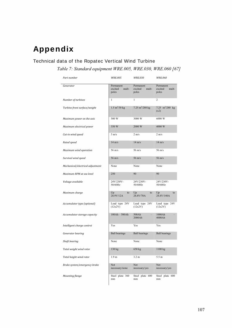
107
Appendix Technical data of the Ropatec Vertical Wind Turbine
Table 7: Standard equipment WRE.005, WRE.030, WRE.060 [67]
Partnumber WRE.005 WRE.030 WRE.060
Generator Permanent excited mult-poles
Permanent excited mult-poles
Permanent excited mult-poles
Numberofturbines 1 1 2
Turbinefrontsurface/weight 1.5 m2/30 kg 7.25 m2/280 kg 7.25 m2/280 kg (x2)
Maximumpowerontheaxis 500 W 3000 W 6000 W
Maximumelectricalpower 350 W 2000 W 4000 W
Cut‐inwindspeed 3 m/s 2 m/s 2 m/s
Ratedspeed 14 m/s 14 m/s 14 m/s
Maximumwindoperation 56 m/s 56 m/s 56 m/s
Survivalwindspeed 56 m/s 56 m/s 56 m/s
Mechanical/electricaladjustment None None None
MaximumRPMatsealevel 250 90 90
Voltageavailable 24V/230V-50/60Hz
24V/230V-50/60Hz
24V/230V-50/60Hz
Maximumcharge Up to 28.9V/12A
Up to 28.8V/70A
Up to 28.8V/140A
Accumulatortype(optional) Lead type 24V (12x2V)
Lead type 24V (12x2V)
Lead type 24V (12x2V)
Accumulatorstoragecapacity 100Ah – 500Ah 500Ah – 2000Ah
1000Ah – 4000Ah
Intelligentchargecontrol Yes Yes Yes
Generatorbearing Ball bearings Ball bearings Ball bearings
Shaftbearing None None None
Totalweightwindrotor 130 kg 650 kg 1100 kg
Totalheightwindrotor 1.9 m 3.2 m 5.5 m
Brakesystem/emergencybrake Not necessary/none
Not necessary/yes
Not necessary/yes
Mountingflange Steel plate 360 mm
Steel plate 600 mm
Steel plate 600 mm
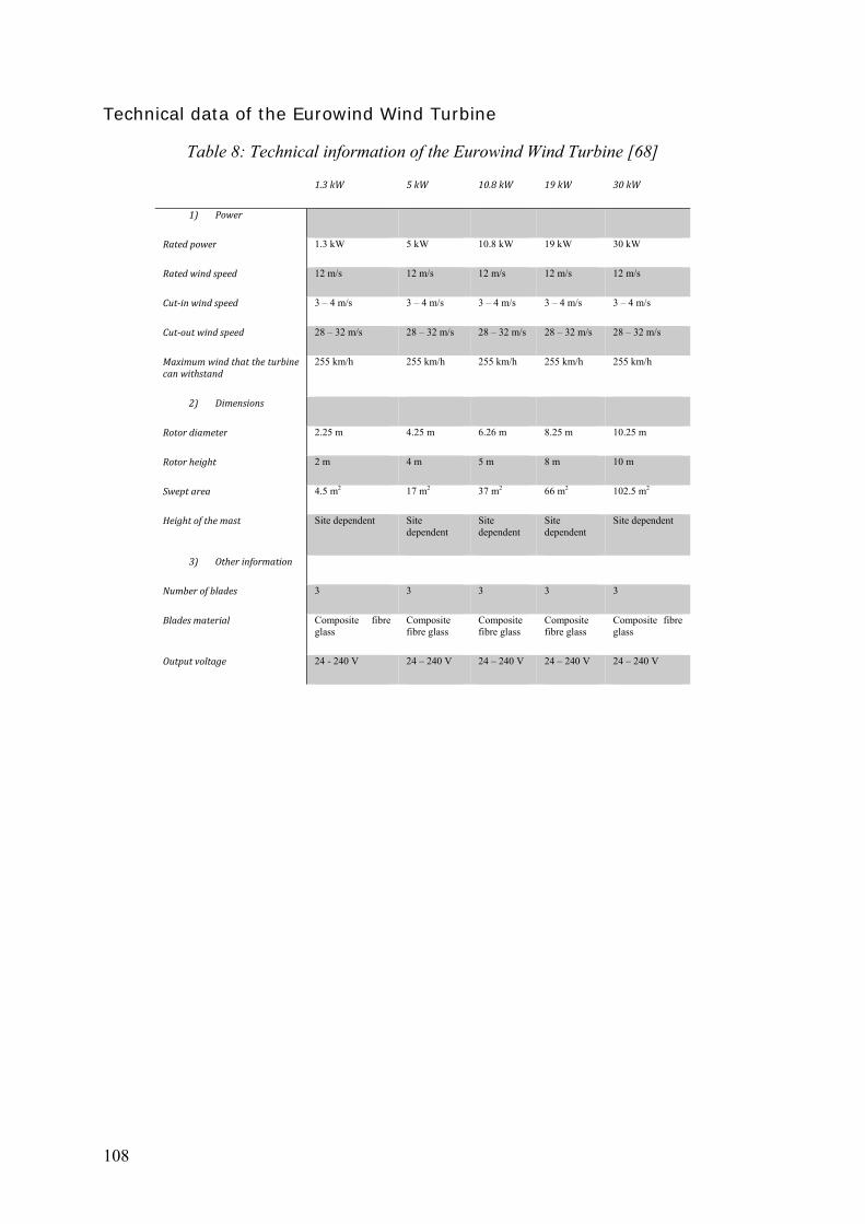
108
Technical data of the Eurowind Wind Turbine
Table 8: Technical information of the Eurowind Wind Turbine [68]
1.3kW 5kW 10.8kW 19kW 30kW
1) Power
Ratedpower 1.3 kW 5 kW 10.8 kW 19 kW 30 kW
Ratedwindspeed 12 m/s 12 m/s 12 m/s 12 m/s 12 m/s
Cut‐inwindspeed 3 – 4 m/s 3 – 4 m/s 3 – 4 m/s 3 – 4 m/s 3 – 4 m/s
Cut‐outwindspeed 28 – 32 m/s 28 – 32 m/s 28 – 32 m/s 28 – 32 m/s 28 – 32 m/s
Maximumwindthattheturbinecanwithstand
255 km/h 255 km/h 255 km/h 255 km/h 255 km/h
2) Dimensions
Rotordiameter 2.25 m 4.25 m 6.26 m 8.25 m 10.25 m
Rotorheight 2 m 4 m 5 m 8 m 10 m
Sweptarea 4.5 m2 17 m2 37 m2 66 m2 102.5 m2
Heightofthemast Site dependent Site dependent
Site dependent
Site dependent
Site dependent
3) Otherinformation
Numberofblades 3 3 3 3 3
Bladesmaterial Composite fibre glass
Composite fibre glass
Composite fibre glass
Composite fibre glass
Composite fibre glass
Outputvoltage 24 - 240 V 24 – 240 V 24 – 240 V 24 – 240 V 24 – 240 V
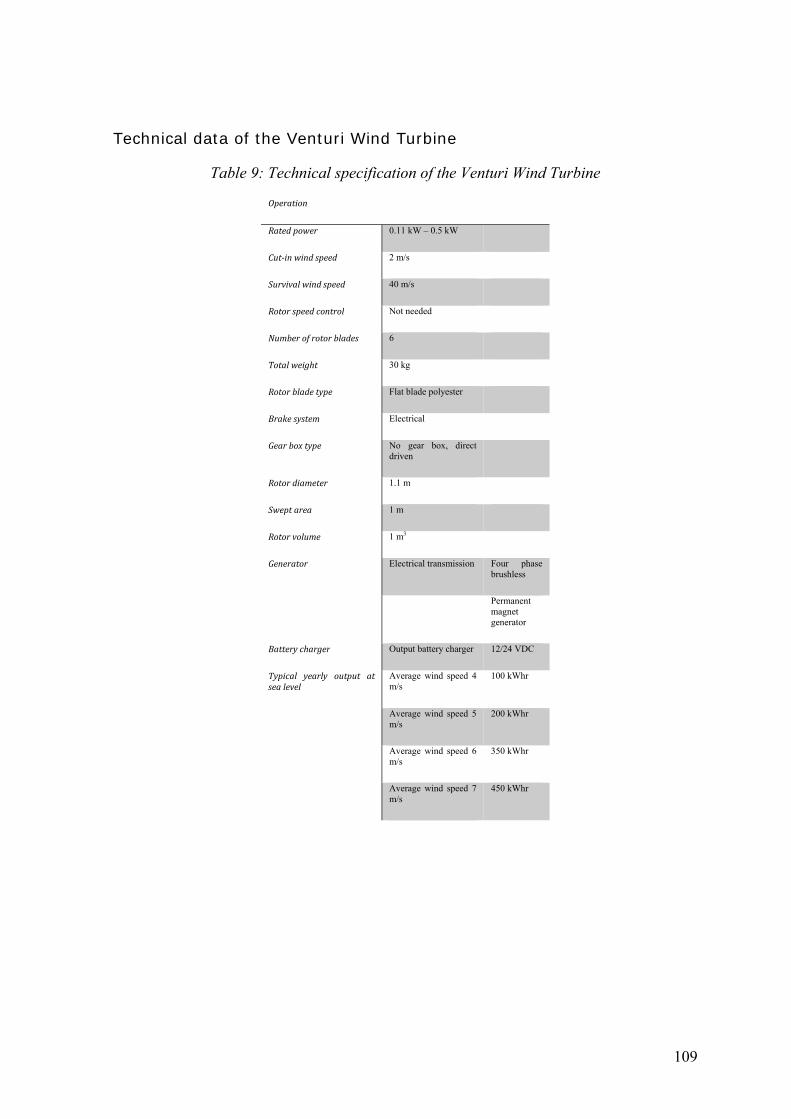
109
Technical data of the Venturi Wind Turbine
Table 9: Technical specification of the Venturi Wind Turbine
Operation
Ratedpower 0.11 kW – 0.5 kW
Cut‐inwindspeed 2 m/s
Survivalwindspeed 40 m/s
Rotorspeedcontrol Not needed
Numberofrotorblades 6
Totalweight 30 kg
Rotorbladetype Flat blade polyester
Brakesystem Electrical
Gearboxtype No gear box, direct driven
Rotordiameter 1.1 m
Sweptarea 1 m
Rotorvolume 1 m3
Generator Electrical transmission Four phase brushless
Permanent magnet generator
Batterycharger Output battery charger 12/24 VDC
Typical yearly output atsealevel
Average wind speed 4 m/s
100 kWhr
Average wind speed 5 m/s
200 kWhr
Average wind speed 6 m/s
350 kWhr
Average wind speed 7 m/s
450 kWhr

110
Technical data of the Turby Wind Turbine
Table 10: Technical specification of the operation
Operation
Cut‐inwindspeed 4 m/s
Ratedwindspeed 14 m/s
Survivalwindspeed 55 m/s
Ratedrotationalspeed 120 – 400 rpm
Ratedbladespeed 42 m/s
Ratedpowerat14m/s 2.5 kW
Table 11: Technical specifications of the turbine of Turby wind turbine
Turbine
Overallheight 2890 mm
Weight(includingblades) 136 kg
Baseflange
Diameter 250 mm
Boltcircle 230 mm
Boltholes 6xM10
Rotor
Diameter 1999 mm
Height 2650 mm
Rotorblades
Number 3
Material Composite
Weight(3blades) 14 kg
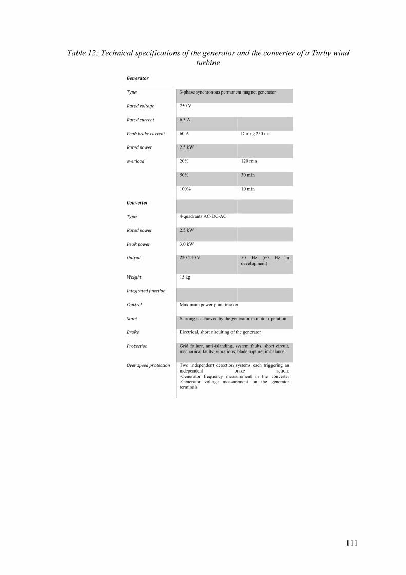
111
Table 12: Technical specifications of the generator and the converter of a Turby wind turbine
Generator
Type 3-phase synchronous permanent magnet generator
Ratedvoltage 250 V
Ratedcurrent 6.3 A
Peakbrakecurrent 60 A During 250 ms
Ratedpower 2.5 kW
overload 20% 120 min
50% 30 min
100% 10 min
Converter
Type 4-quadrants AC-DC-AC
Ratedpower 2.5 kW
Peakpower 3.0 kW
Output 220-240 V 50 Hz (60 Hz in development)
Weight 15 kg
Integratedfunction
Control Maximum power point tracker
Start Starting is achieved by the generator in motor operation
Brake Electrical, short circuiting of the generator
Protection Grid failure, anti-islanding, system faults, short circuit, mechanical faults, vibrations, blade rupture, imbalance
Overspeedprotection Two independent detection systems each triggering an independent brake action: -Generator frequency measurement in the converter -Generator voltage measurement on the generator terminals
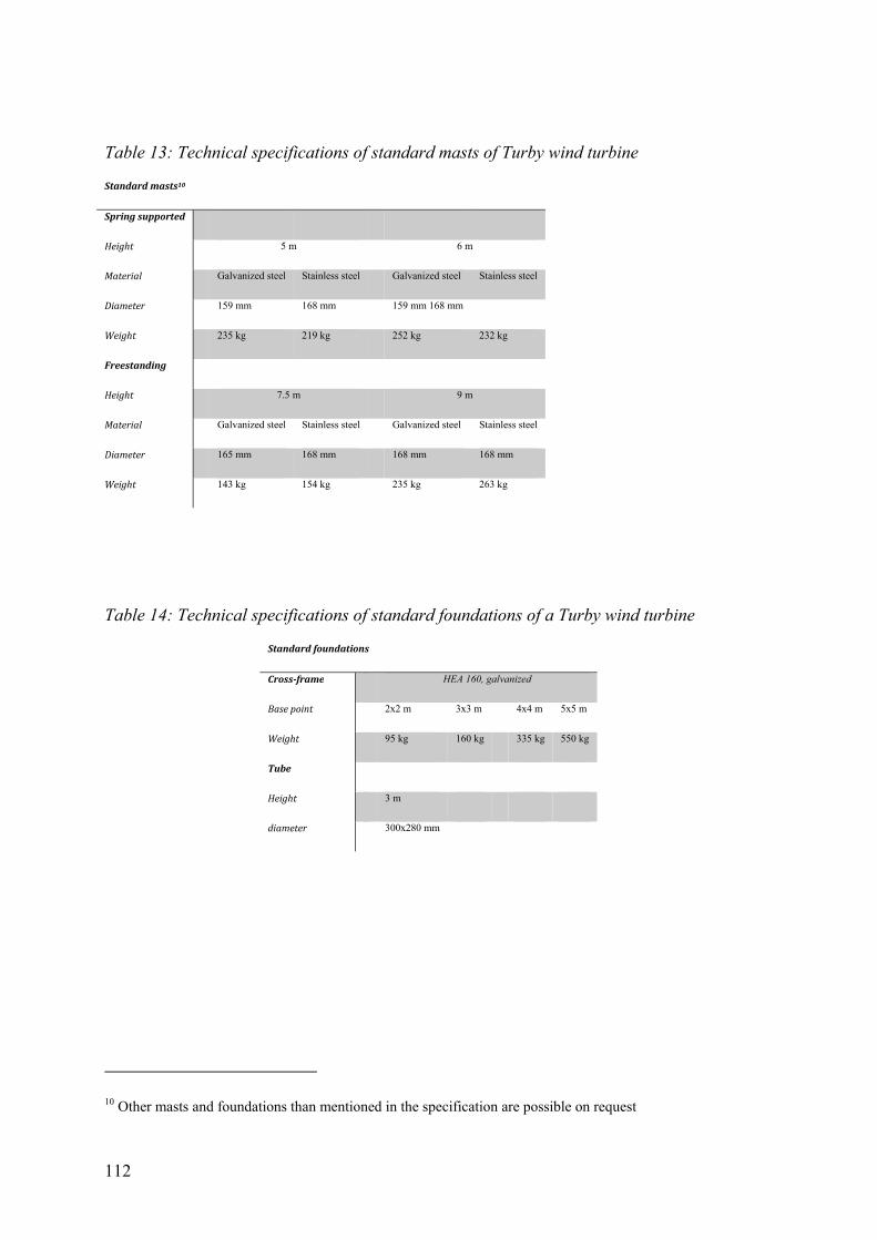
112
Table 13: Technical specifications of standard masts of Turby wind turbine
Standardmasts10
Springsupported
Height 5 m 6 m
Material Galvanized steel Stainless steel Galvanized steel Stainless steel
Diameter 159 mm 168 mm 159 mm 168 mm
Weight 235 kg 219 kg 252 kg 232 kg
Freestanding
Height 7.5 m 9 m
Material Galvanized steel Stainless steel Galvanized steel Stainless steel
Diameter 165 mm 168 mm 168 mm 168 mm
Weight 143 kg 154 kg 235 kg 263 kg
Table 14: Technical specifications of standard foundations of a Turby wind turbine
Standardfoundations
Cross‐frame HEA 160, galvanized
Basepoint 2x2 m 3x3 m 4x4 m 5x5 m
Weight 95 kg 160 kg 335 kg 550 kg
Tube
Height 3 m
diameter 300x280 mm
10 Other masts and foundations than mentioned in the specification are possible on request
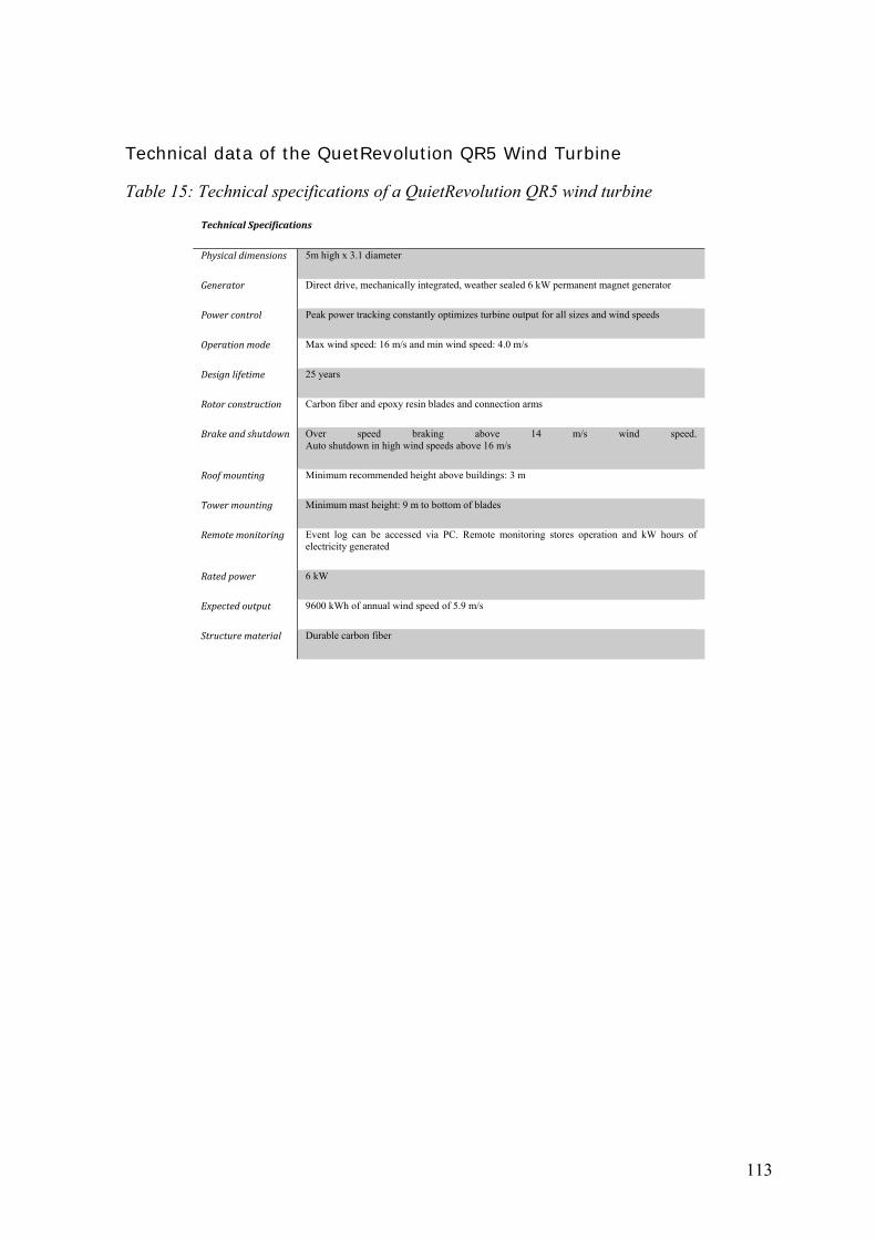
113
Technical data of the QuetRevolution QR5 Wind Turbine
Table 15: Technical specifications of a QuietRevolution QR5 wind turbine
TechnicalSpecifications
Physicaldimensions 5m high x 3.1 diameter
Generator Direct drive, mechanically integrated, weather sealed 6 kW permanent magnet generator
Powercontrol Peak power tracking constantly optimizes turbine output for all sizes and wind speeds
Operationmode Max wind speed: 16 m/s and min wind speed: 4.0 m/s
Designlifetime 25 years
Rotorconstruction Carbon fiber and epoxy resin blades and connection arms
Brakeandshutdown Over speed braking above 14 m/s wind speed. Auto shutdown in high wind speeds above 16 m/s
Roofmounting Minimum recommended height above buildings: 3 m
Towermounting Minimum mast height: 9 m to bottom of blades
Remotemonitoring Event log can be accessed via PC. Remote monitoring stores operation and kW hours of electricity generated
Ratedpower 6 kW
Expectedoutput 9600 kWh of annual wind speed of 5.9 m/s
Structurematerial Durable carbon fiber

114
Technical data of the Windspire Wind Turbine
Table 16: Technical specifications for standard Windspire wind turbine [59] [75]
TechnicalSpecifications
Cut‐inwindspeed 3.8 m/s
Averagewindspeed 5.0 m/s
IPRratedwindspeed 11.0 m/s
Survivalwindspeed 47 m/s
Annualenergyproduction 2000 kWh
Ratedpower 1200 watts
Instantaneouspowerrating 1.2 kW
Standardunitheight 9.1 m (pole extension available)
Totalweight 283 kg
Unitcolor Light grey
Soundoutput Imperceptible at 4.5 m/s and 8.8 dB above ambient at 22 m/s
Rotortype Vertical Axis Darrieus Low Speed Giromill
Rotorheight 6.1 m
Radius 0.6 m
Sweptarea 7.43 m2
Maximumrotorspeed 408 RPM
PeakTSR 2.8
Speedcontrol Dual Reduntant: passive aerodynamic, electronic
WindTracking Instantaneous
Generator High efficiency brushless permanent magnet, ETL certified
Inverter Custom integrated grid tie 120 VAC 60 Hz and 230 VAC 50 Hz
Invertercertification ETL: Meets IEEE 1547.1; UL 1741, CE, EN 50178, EN 50438, AS/NZS 3100, AS/NZS 4777.2, 4777.2, ESO11009
Performancemonitor Integrated wireless Zigbee modem
Warranty 5 years
Foundation Poured concrete
Foundationsize 0.6 m diameter with 1.8 m base
Rotormaterial Aircraft grade extruded aluminum
Monopole/structurematerial Recycled high grade steel

115


![[WIND POWER GENERATION FOR A GENERIC HOUSEHOLD ] 2009/Projects... · A vertical axis wind turbine (VAWT) has a vertical axis in contrast to the conventional horizontal turbines most](https://img.pdfslide.us/doc/110x75/5f02d5dc7e708231d4063fac/wind-power-generation-for-a-generic-household-2009projects-a-vertical-axis.jpg)