Embed Size (px)
Citation preview

International Journal on Electrical Engineering and Informatics - Volume 8, Number 4, December 2016
A Fuzzy Direct Torque Control of Induction Motor
for FPGA Implementation
Yosr Bchir, Soufien Gdaim, and Abdellatif Mtibaa
Laboratory of Electronics and Micoelectronics of the FSM National Engineering School of Monastir,
Avenue Ibn ElJazzar, 5019 Monastir, University of Monastir, Tunisia.
Abstract: This paper resumes a Direct Torque Fuzzy Control (DTFC) of an Induction Motor
(IM). The novel approach aims to ameliorate the performances of the conventional Direct
Torque Control (DTC) by considerably reducing electromagnetic torque and stator flux ripples
and improving the form of stator current. The proposed controller is based on fuzzy logic
technique and it is developed in order to be implemented on Field Programmable Gate Array
chip (FPGA) by using Matlab/Simullink package and Xilinx System Generator (XSG) toolbox.
The efficiency of proposed technique is evaluated through simulative results that show its
performance compared to conventional one.
Keywords: DTC, IM, DTFC, XSG, FPGA
1. Introduction
Different techniques of induction machine drive have been introduced in order to ensure
speed control at variable frequency. Direct Torque Control (DTC) technique was proposed in
the middle of the 1980s by I. Takahashi. It is considered as the most advanced AC drive
technology; indeed, it presented many advantages compared to previous ones such as scalar
control and vector control [1]-[2]. In fact, DTC has the advantages of a fast torque and flux
response and no need for a modulator as used in Pulse Width Modulation (PWM) to control the
frequency and the voltage since the inverter is controlled directly by the voltage vectors
through a switching table indeed, DTC is essentially based on determining the sequence of
control applied to the inverter switches at each switching time.. Besides, DTC’s structure is
simple without Park transformation in the electrical machine’s model and the estimation of
control variables that are stator flux and torque are estimated without tachometer or encoder to
monitor motor shaft speed or position. [1] [3].
In spite of all the mentioned advantages of DTC compared with other control techniques, it
has the disadvantage of having a variable switching frequency with fixed hysteresis bands; this
is the main cause of undesired ripples generation. These ripples are the source of other
problems such as audible noise. In order to overcome these disadvantages, many improvements
have been realized in order to ameliorate conventional DTC dynamic performance while
preserving the advantages of the conventional DTC structure.
In [4] and [5] a prediction technique is employed to improve the conventional DTC’s
torque and flux ripple performance; the proposed controllers predicts several/future switch
transitions and choose the adequate sequence of inverter switch positions so that the switching
frequency is reduced. And in [6] authors proposed a predictive direct torque control DTC
algorithm for induction machine drives including a Sliding Horizon Prediction. In [7] an
analytical approach to select the hysteresis bands of DTC to achieve constant switching
frequency and lower Total Harmonic Distorsion (THD) in motor currents has been presented.
In [8] authors presented a novel space vector modulation based on twelve 30° sectors of flux
and voltage vectors within a circular locus of space vector for Induction motor control based
DTC. The reference [9] detailed an improved DTC which is based on a Sliding Mode Direct
Torque Control (SM-DTC) of IM drive and in [10] the Artificial Neural Networks ANN-
based DTC of an IM was developed. While authors in [11] investigate the application of both
ANN to Conventional DTC and SVM_ DTC to improve the performances of conventional
Received: June 13rd
, 2015. Accepted: December 19th
, 2016
DOI: 10.15676/ijeei.2016.8.4.11
851
DTC. In [12] authors presented some variety of DTC combined with Field Oriented Control
(FOC) structures: Hysteresis controllers and switching table are replaced by Proportional
Integral PI controllers and space vector modulator(SVM). Three algorithms work in fixed
switching frequency are developed: Direct Voltage Control (DVC) Direct Torque Control with
Space Vector Modulation (DTC-SVM) and DTC-SVM with Closed – Loop Flux Control
(DFC). In [13] authors combined the DTC-SVM structure with an observer for both
torque/flux and speed sensorless control including flux weakening rang. In [14] a
modified DTC approach which use a three-level inverter (Neutral Point Clamped (NPC)
structure) instead of the two-level inverter and a PI fuzzy controller instead the classic PI
controller was developed.
Some improvements based on artificial intelligence and specifically on fuzzy logic was
realized: In [15] and [16], authors presented and discussed the efficiency of a Fuzzy Logic
Controller (FLC) for the DTC of an IM for FPGA implementation. The proposed design is
developed by a hardware description based on the VHSIC Hardware Description Language
(VHDL) hardware description language. In [17] an improvement of the Conventional DTC of
an induction motor is presented. The Fuzzy Logic is introduced at the PI controller of speed to
be implemented on FPGA.
This paper describes a novel approach of DTC based on fuzzy logic. The fuzzy controller is
developed by using XSG software packages to be implemented on FPGA. It’s shown to be able
to reduce electromagnetic torque and flux ripples by simulative results. This paper is organized
as follows: section 2 presents the adequate model of IM designed for DTC, in section 3 the
principle of conventional DTC is presented, section 4 contained the basic principle of Direct
Torque Fuzzy Control (DTFC), section 5 is about presenting the DTFC approach using XSG,
in section 6 simulation and interpretation results are developed and finally the procedure of
FPGA implementation of the DTFC is given.
2. Modeling of Induction Motor for DTC
The IM can be modeled in terms of stator flux s and stator current si in the reference
(α,β) as shown in the following expression:
1 1 1( ) ( )
s sss
s r r s s
ss ss
di Vj i j
dt
dR i V
dt
(1)
Where , ,s r ml l l are respectively stator, rotor and mutual inductance, s rR R denote stator
and rotor resistance, s s
l 2
1 m
s r
l
l l s r
s r
s r
l land
R R
Stator flux and stator current in the stationary reference frame (α, β) are considered as the
state variables of the system while vector control consists of the components of stator voltage
as mentioned below:
[ ]T
s s s sx i i
s su V V
Equations system in (1) can be evaluated using the matrix vector form into the following state
space representation:
Yosr Bchir, et al.
852
d x
A x B udt
Where
1 1 1 1
( ) ( )( )
0 1
s r r s s s
s
j jA B
R
(2)
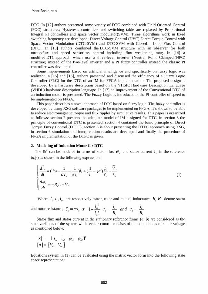
3. Conventional DTC principle
DTC technique is based on choosing the optimum vector of the voltage. This makes the
stator flux rotate and consequently produce the desired torque. The structure of DTC contains
mainly two loops of the control variables: the electromagnetic torque and the stator flux. It’s
illustrated on figure.1. A two level hysteresis comparator has the role of comparing the
estimated stator flux magnitude with its reference value while a three level hysteresis
comparator calculates the error between the estimated torque and the reference torque. The
error of Electromagnetic torque and stator flux’s error and sector are the inputs of a switching
table which generates the adequate sequence of inverter control [18]. The sequences of inverter
control are given through a switching table which generates control commands taking as inputs
the sector of stator flux vector and the errors of the torque and flux. The error signals are given
by two hysteresis regulators whose role is to compare estimates with those of reference data in
order to maintain their values within hysteresis bands. This requires the use of estimators of the
control values. In the following paragraph we give the procedure of the determination of
required values.
Eφ Ec S1 S2 S3 S4 S5 S6
1 1 V2 V3 V4 V5 V6 V1
0 V7 V0 V7 V0 V7 V0
-1 V6 V1 V2 V3 V4 V5
0 1 V3 V4 V5 V6 V1 V2
0 V0 V7 V0 V7 V0 V7
-1 V5 V6 V1 V2 V3 V4
-
+
-
eφ
ec
N
Voltage
source
inverter
IM
Switching Table
Sa Sb Sc
φ*
Te*
φs
Te
θs
Stator Flux & Torque Estimator
dtIRV SSSS )(
( )e s s s sp i i
ia ib
E
-
+
+
+
Figure 1. Block Diagram of Conventional Direct Torque Control
The choice of the control sequence applied to the switches of a three-phase voltage inverter
is based essentially on the use of hysteresis comparators. Hysteresis bands allow avoiding
unnecessary switching when the calculated error is very small. Thus, stator flux vector is kept
in a circular crown. Control sequence of the inverter switches voltage is then defined by:
The output value of the electromagnetic torque three levels hysteresis comparator
The output value of the stator flux two levels hysteresis comparator
The position of the stator flux vector in the reference (α, β)
These variables are used as inputs in the switching table of TAKASHI illustrated by Table 1
and which enables the determination of the voltage vector.
A Fuzzy Direct Torque Control of Induction Motor
853
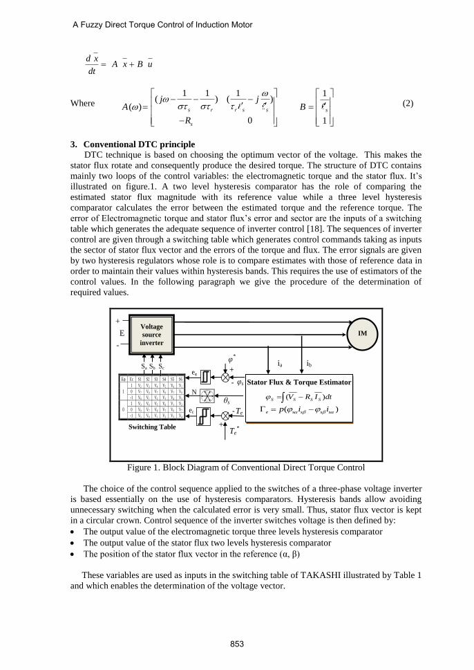
4. Stator flux estimation
Table 1. The switching Table for basis DTC
A. Stator flux estimation
0
0
( . )
( . )
t
s s s s
t
t
s s s s
t
v R i dt
v R i dt
(3)
Stator flux magnitude is the square root of the squared components: 2 2
s s s
Where the components of stator voltage vector are defined in terms of switch control variables
SA,SB and SC in equation (4) and the components of stator current are established in equation
(5) by applying Concordia form to currents components ia and ib
0
132 2
s A B cV U S S S
01
2s B cV U S S (4)
32
1 2
s a
s b c
i i
i i i
(5)
B. Electromagnetic torque estimation
Electromagnetic torque can be estimated from the components of the stator flux and current
in the reference (α, β) using the equation (6):
. .e s s s sp i i (6)
C. Position of the stator flux vector
The angle between stator flux vector and the axis α of the stationary reference is evaluated by
the following expression:
1tan s
s
s
(7)
Sector 1 2 3 4 5 6
ef ec
1
1 V2 V3 V4 V5 V6 V1
0 V7 V0 V7 V0 V7 V0
-1 V6 V1 V2 V3 V4 V5
0
1 V3 V4 V5 V6 V1 V2
0 V0 V7 V0 V7 V0 V7
-1 V5 V6 V1 V2 V3 V4
Yosr Bchir, et al.
854
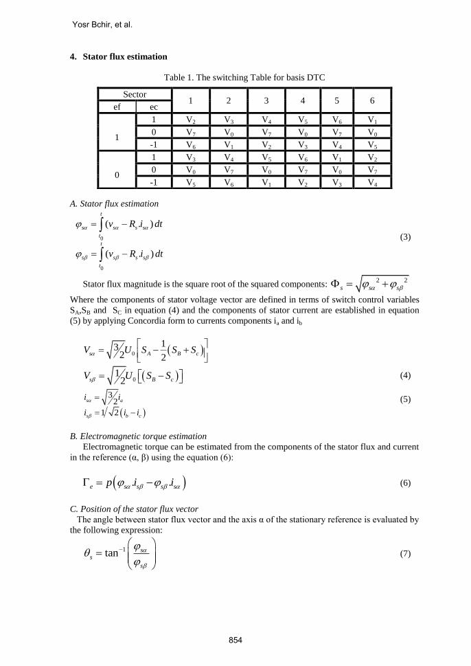
4. Direct Torque Fuzzy Control principle In order to improve the conventional DTC principle, it’s interesting to incorporate
intelligent controllers as fuzzy logic, neuronal network neuro-fuzzy, etc. These controllers are
known by their design that does not depend on accurate mathematical model of the system and
thus it handles nonlinearity of arbitrary complexity [19].
They are used to ameliorate the conventional controller and particularly decrease torque
and flux ripples. These ripples are due to hysteresis regulators‘use and which act directly on the
variables control: stator flux and electromagnetic torque. It is noted that these ripples are the
main disadvantage of the DTC since they can cause vibration and audible noise in the
induction motor and eventually results the degradation of some components.
The Direct Torque fuzzy Control Scheme (DTFC) is given by Figure2 In fuzzy approach, the
two hysteresis comparators and the switching table are substituted by a fuzzy controller [20]
[21].
eφ
eT
Voltage
source
inverter
IM
Sa Sb Sc
φ*
Te*
φs
Te
θs
Stator Flux & Torque Estimator
dtIRV SSSS )(
( )e s s s sT p i i
iA iB
E
-
+
Fuzzy controller -
-
+
+
Figure 2. Block Diagram of Direct Torque Fuzzy Control
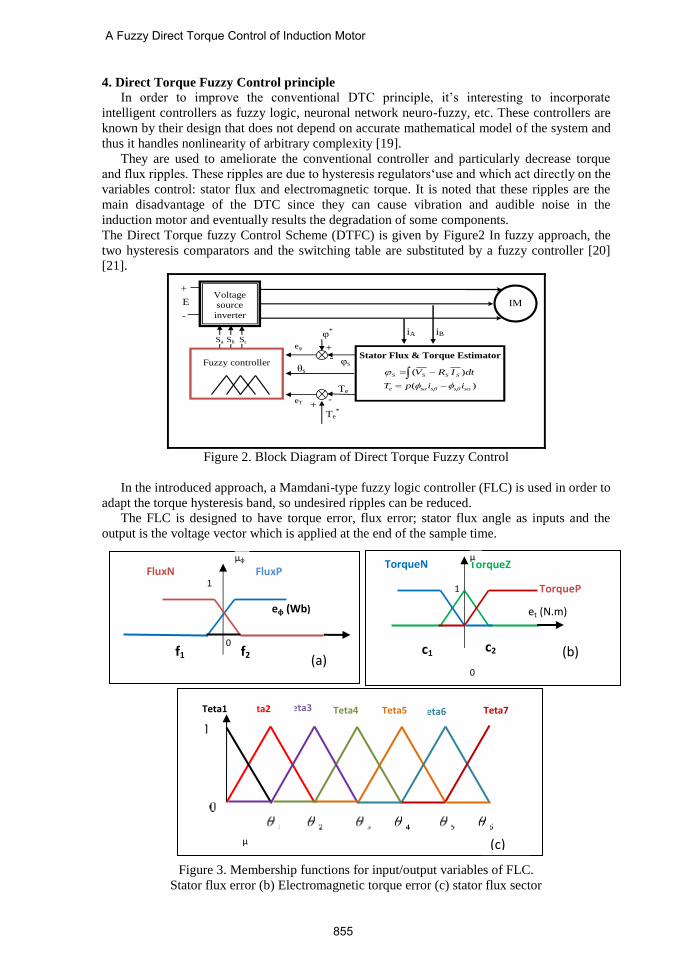
In the introduced approach, a Mamdani-type fuzzy logic controller (FLC) is used in order to
adapt the torque hysteresis band, so undesired ripples can be reduced.
The FLC is designed to have torque error, flux error; stator flux angle as inputs and the
output is the voltage vector which is applied at the end of the sample time.
Figure 3. Membership functions for input/output variables of FLC.
Stator flux error (b) Electromagnetic torque error (c) stator flux sector
0
FluxN FluxP
f2 f1
μφ
1
eφ (Wb)
(a) 0
c2 c1
TorqueZ TorqueN
TorqueP
et (N.m)
μ
1
(b)
μ
1
Teta7 Teta6 Teta5 Teta3 Teta2 Teta1 Teta4
(c)
A Fuzzy Direct Torque Control of Induction Motor
855
The stator flux error can be negative (FluxN) or postive (FluxP) corresponding to 2
overlapping fuzzy sets. The flux error membership function is represented by two symmetric
trapezoidal membership functions. The torque error membership function is represented by
three fuzzy sets as shown in Figure3.(b) with delta and trapezoidal shape. Its membership is
named negative torque error (TorqueN), Zero torque error (TorqueZ) and Positive torque error
(TorqueP).The flux angle has a universe of discourse equal 360 degrees ([0,2π]). It is divided
into six sectors. the universe of the discourse of this fuzzy variable is divided into six fuzzy sets
denoted θ1 to θ7 with a width of π/3as shown in Figure 3.c. The associated membership
functions are defined by six equidistant isosceles triangular membership functions are used
named as Teta1, Teta2, Teta3, Teta4, Teta5, Teta6 and Teta7.
The bases of rules for direct torque fuzzy control are developed by the use of TAKASHI
table given in Table.2
Table. 2 Voltage vector fuzzy control table
Each control rule can be described using the input variables torque error et, flux error ef,
flux angle θ and the output variable V as:
If (ef is A) AND (et is B) AND (θ is C) THEN (V is Vi) Where A, B and C are the fuzzy set
of the input variables.
The developed FLC uses the method of SOM (the Smallest Of Maximum) in the
defuzzification process .It returns the smallest output with the maximum membership function
as the crisp value. [23]
The design of the developed controller is empirical and defined by the simulation of the
system that enables the choice of adequate parameters for the defined application. Simulation is
realized by using Matlab/Simulink environment in order to have the optimum level of torque
ripples [22]. The performance of the FLC is mainly influenced by the shape of the membership
function, the fuzzy reasoning rules and the defuzzification method.
5. DTFC based FPGA Design using XSG
XSG generates a synthesizable code VHDL to be used for Xilinx FPGA chip
implementation. It’s a toolbox developed for MATLAB/Simulink which enable an abstraction
algorithm level while keeping traditional Simulink blocksets [24] - [26]. In this section the
detailed XSG design of the FLC’s different parts are presented.
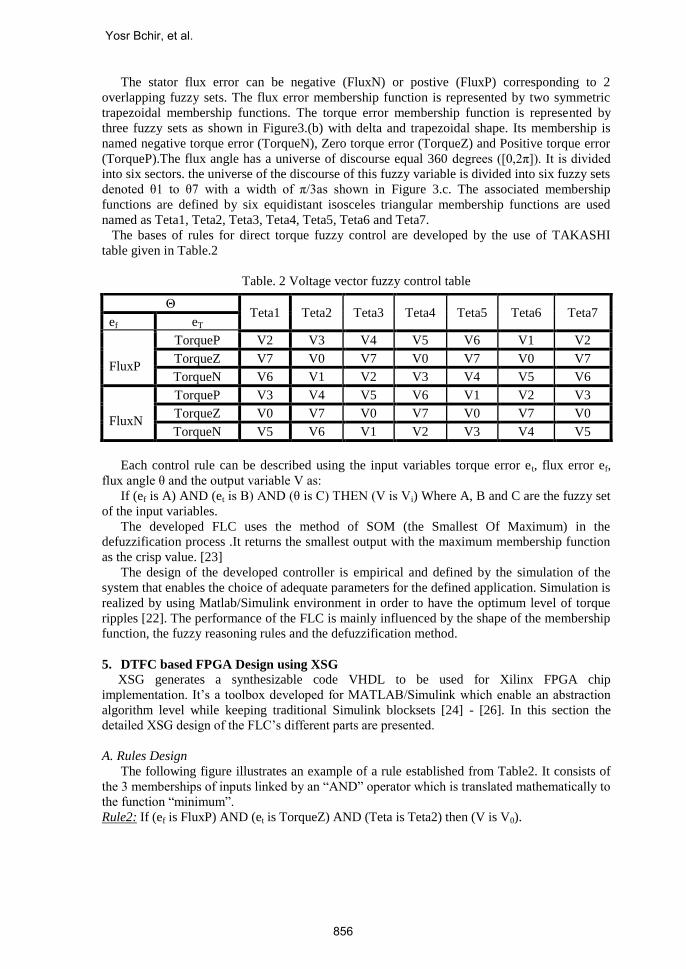
A. Rules Design
The following figure illustrates an example of a rule established from Table2. It consists of
the 3 memberships of inputs linked by an “AND” operator which is translated mathematically to
the function “minimum”.
Rule2: If (ef is FluxP) AND (et is TorqueZ) AND (Teta is Teta2) then (V is V0).
Θ Teta1 Teta2 Teta3 Teta4 Teta5 Teta6 Teta7
ef eT
FluxP
TorqueP V2 V3 V4 V5 V6 V1 V2
TorqueZ V7 V0 V7 V0 V7 V0 V7
TorqueN V6 V1 V2 V3 V4 V5 V6
FluxN
TorqueP V3 V4 V5 V6 V1 V2 V3
TorqueZ V0 V7 V0 V7 V0 V7 V0
TorqueN V5 V6 V1 V2 V3 V4 V5
Yosr Bchir, et al.
856
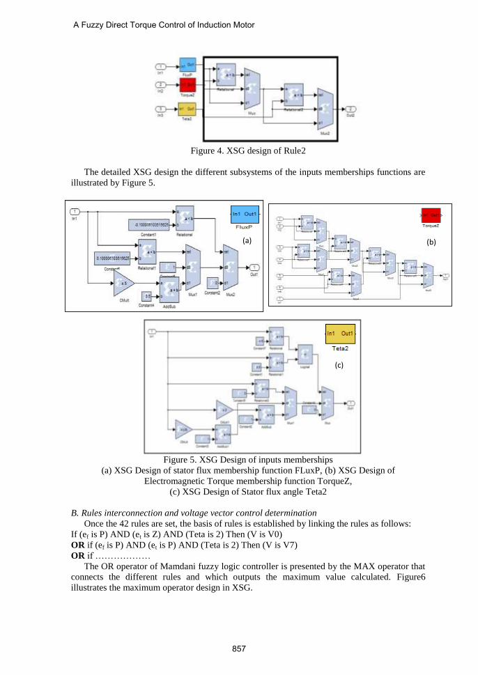
Figure 4. XSG design of Rule2
The detailed XSG design the different subsystems of the inputs memberships functions are
illustrated by Figure 5.
Figure 5. XSG Design of inputs memberships
(a) XSG Design of stator flux membership function FLuxP, (b) XSG Design of
Electromagnetic Torque membership function TorqueZ,
(c) XSG Design of Stator flux angle Teta2
B. Rules interconnection and voltage vector control determination
Once the 42 rules are set, the basis of rules is established by linking the rules as follows:
If (ef is P) AND (et is Z) AND (Teta is 2) Then (V is V0)
OR if (ef is P) AND (et is P) AND (Teta is 2) Then (V is V7)
OR if ………………
The OR operator of Mamdani fuzzy logic controller is presented by the MAX operator that
connects the different rules and which outputs the maximum value calculated. Figure6
illustrates the maximum operator design in XSG.
(a)
(b)
(c)
(b)
A Fuzzy Direct Torque Control of Induction Motor
857
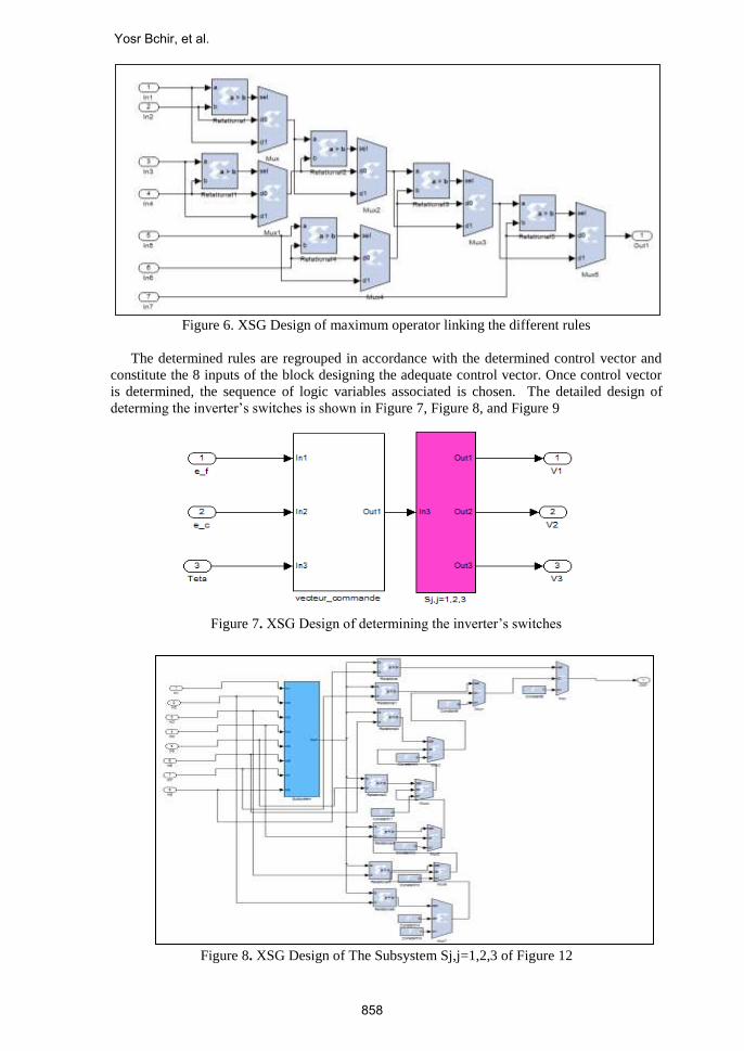
Figure 6. XSG Design of maximum operator linking the different rules
The determined rules are regrouped in accordance with the determined control vector and
constitute the 8 inputs of the block designing the adequate control vector. Once control vector
is determined, the sequence of logic variables associated is chosen. The detailed design of
determing the inverter’s switches is shown in Figure 7, Figure 8, and Figure 9
Figure 7. XSG Design of determining the inverter’s switches
Figure 8. XSG Design of The Subsystem Sj,j=1,2,3 of Figure 12
Yosr Bchir, et al.
858
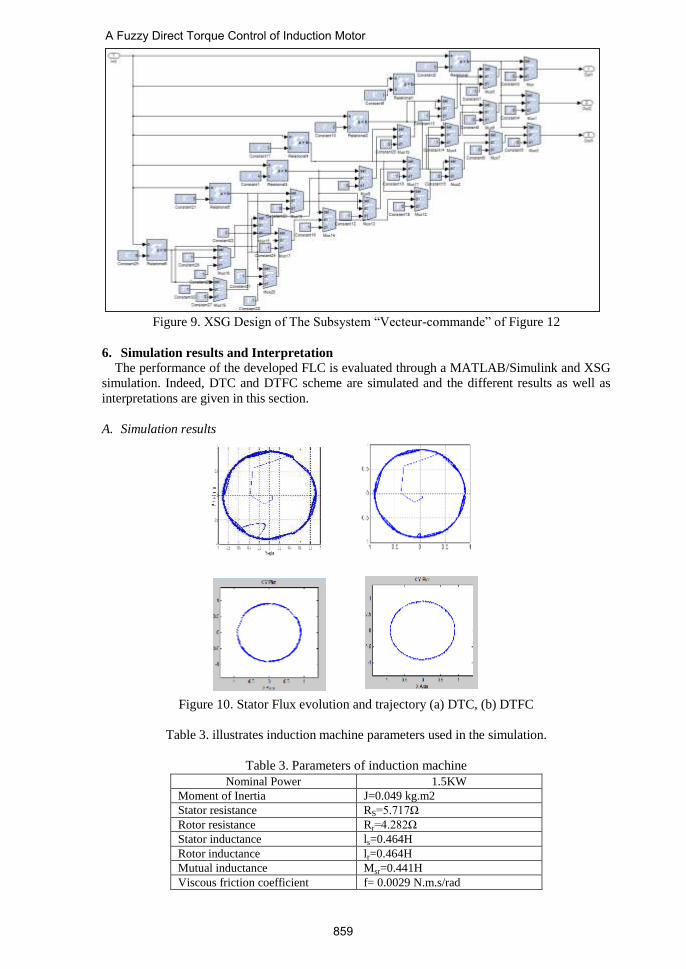
Figure 9. XSG Design of The Subsystem “Vecteur-commande” of Figure 12
6. Simulation results and Interpretation
The performance of the developed FLC is evaluated through a MATLAB/Simulink and XSG
simulation. Indeed, DTC and DTFC scheme are simulated and the different results as well as
interpretations are given in this section.
A. Simulation results
Figure 10. Stator Flux evolution and trajectory (a) DTC, (b) DTFC
Table 3. illustrates induction machine parameters used in the simulation.
Table 3. Parameters of induction machine
Nominal Power 1.5KW
Moment of Inertia J=0.049 kg.m2
Stator resistance RS=5.717Ω
Rotor resistance Rr=4.282Ω
Stator inductance ls=0.464H
Rotor inductance lr=0.464H
Mutual inductance Msr=0.441H
Viscous friction coefficient f= 0.0029 N.m.s/rad
A Fuzzy Direct Torque Control of Induction Motor
859
The Electromagnetic torque and flux references used in the simulation are equal to 10 N.m
and 0.91 wb respectively. The sampling period of the system is 50 μs.
We obtain in Figure10, Fig .11, Figure12, the evolution of stator flux evolution and
trajectory, electromagnetic torque and stator current in the cases of DTC and DTFC scheme
respectively.
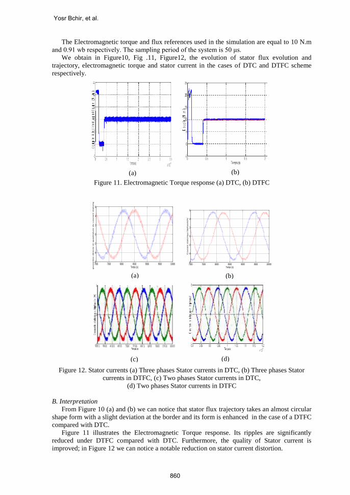
Figure 11. Electromagnetic Torque response (a) DTC, (b) DTFC
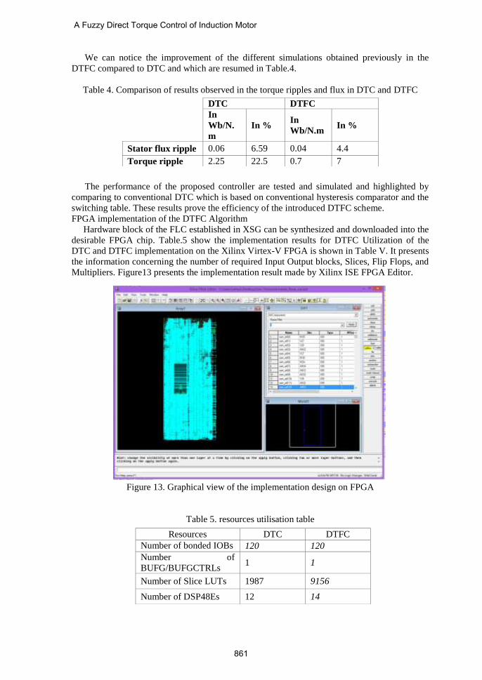
Figure 12. Stator currents (a) Three phases Stator currents in DTC, (b) Three phases Stator
currents in DTFC, (c) Two phases Stator currents in DTC,
(d) Two phases Stator currents in DTFC
B. Interpretation
From Figure 10 (a) and (b) we can notice that stator flux trajectory takes an almost circular
shape form with a slight deviation at the border and its form is enhanced in the case of a DTFC
compared with DTC.
Figure 11 illustrates the Electromagnetic Torque response. Its ripples are significantly
reduced under DTFC compared with DTC. Furthermore, the quality of Stator current is
improved; in Figure 12 we can notice a notable reduction on stator current distortion.
7000 7500 8000 8500 9000 9500 10000-6
-4
-2
0
2
4
6
Temps (s)
Com
posantes directe et quadrature du courant statoriq
ue (A
)
7000 7500 8000 8500 9000 9500 10000-6
-4
-2
0
2
4
6
Temps (s)
Courant statoriq
ur bip
hasé(A
)
(a) (b)
(c) (d)
(a) (b)
Yosr Bchir, et al.
860
We can notice the improvement of the different simulations obtained previously in the
DTFC compared to DTC and which are resumed in Table.4.
Table 4. Comparison of results observed in the torque ripples and flux in DTC and DTFC
The performance of the proposed controller are tested and simulated and highlighted by
comparing to conventional DTC which is based on conventional hysteresis comparator and the
switching table. These results prove the efficiency of the introduced DTFC scheme.
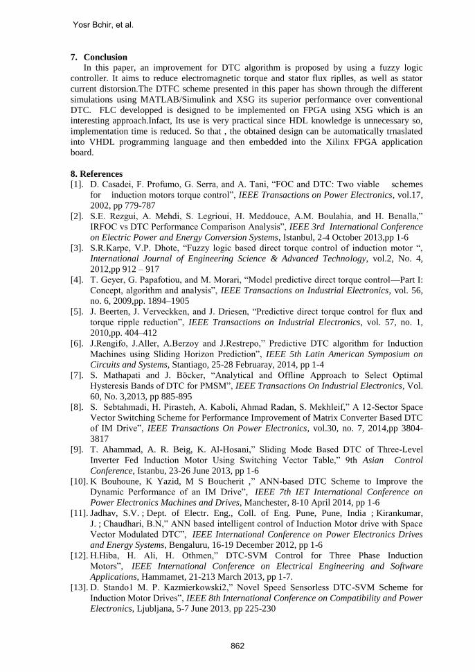
FPGA implementation of the DTFC Algorithm
Hardware block of the FLC established in XSG can be synthesized and downloaded into the
desirable FPGA chip. Table.5 show the implementation results for DTFC Utilization of the
DTC and DTFC implementation on the Xilinx Virtex-V FPGA is shown in Table V. It presents
the information concerning the number of required Input Output blocks, Slices, Flip Flops, and
Multipliers. Figure13 presents the implementation result made by Xilinx ISE FPGA Editor.
Figure 13. Graphical view of the implementation design on FPGA
Table 5. resources utilisation table
DTC DTFC
In
Wb/N.
m
In % In
Wb/N.m In %
Stator flux ripple 0.06 6.59 0.04 4.4
Torque ripple 2.25 22.5 0.7 7
Resources DTC DTFC
Number of bonded IOBs 120 120
Number of
BUFG/BUFGCTRLs 1 1
Number of Slice LUTs 1987 9156
Number of DSP48Es 12 14
A Fuzzy Direct Torque Control of Induction Motor
861
7. Conclusion
In this paper, an improvement for DTC algorithm is proposed by using a fuzzy logic
controller. It aims to reduce electromagnetic torque and stator flux riplles, as well as stator
current distorsion.The DTFC scheme presented in this paper has shown through the different
simulations using MATLAB/Simulink and XSG its superior performance over conventional
DTC. FLC developped is designed to be implemented on FPGA using XSG which is an
interesting approach.Infact, Its use is very practical since HDL knowledge is unnecessary so,
implementation time is reduced. So that , the obtained design can be automatically trnaslated
into VHDL programming language and then embedded into the Xilinx FPGA application
board.
8. References
[1]. D. Casadei, F. Profumo, G. Serra, and A. Tani, “FOC and DTC: Two viable schemes
for induction motors torque control”, IEEE Transactions on Power Electronics, vol.17,
2002, pp 779-787
[2]. S.E. Rezgui, A. Mehdi, S. Legrioui, H. Meddouce, A.M. Boulahia, and H. Benalla,”
IRFOC vs DTC Performance Comparison Analysis”, IEEE 3rd International Conference
on Electric Power and Energy Conversion Systems, Istanbul, 2-4 October 2013,pp 1-6
[3]. S.R.Karpe, V.P. Dhote, “Fuzzy logic based direct torque control of induction motor “,
International Journal of Engineering Science & Advanced Technology, vol.2, No. 4,
2012,pp 912 – 917
[4]. T. Geyer, G. Papafotiou, and M. Morari, “Model predictive direct torque control—Part I:
Concept, algorithm and analysis”, IEEE Transactions on Industrial Electronics, vol. 56,
no. 6, 2009,pp. 1894–1905
[5]. J. Beerten, J. Verveckken, and J. Driesen, “Predictive direct torque control for flux and
torque ripple reduction”, IEEE Transactions on Industrial Electronics, vol. 57, no. 1,
2010,pp. 404–412
[6]. J.Rengifo, J.Aller, A.Berzoy and J.Restrepo,” Predictive DTC algorithm for Induction
Machines using Sliding Horizon Prediction”, IEEE 5th Latin American Symposium on
Circuits and Systems, Stantiago, 25-28 Februaray, 2014, pp 1-4
[7]. S. Mathapati and J. Böcker, “Analytical and Offline Approach to Select Optimal
Hysteresis Bands of DTC for PMSM”, IEEE Transactions On Industrial Electronics, Vol.
60, No. 3,2013, pp 885-895
[8]. S. Sebtahmadi, H. Pirasteh, A. Kaboli, Ahmad Radan, S. Mekhleif,” A 12-Sector Space
Vector Switching Scheme for Performance Improvement of Matrix Converter Based DTC
of IM Drive”, IEEE Transactions On Power Electronics, vol.30, no. 7, 2014,pp 3804-
3817
[9]. T. Ahammad, A. R. Beig, K. Al-Hosani,” Sliding Mode Based DTC of Three-Level
Inverter Fed Induction Motor Using Switching Vector Table,” 9th Asian Control
Conference, Istanbu, 23-26 June 2013, pp 1-6
[10]. K Bouhoune, K Yazid, M S Boucherit ,” ANN-based DTC Scheme to Improve the
Dynamic Performance of an IM Drive”, IEEE 7th IET International Conference on
Power Electronics Machines and Drives, Manchester, 8-10 April 2014, pp 1-6
[11]. Jadhav, S.V. ; Dept. of Electr. Eng., Coll. of Eng. Pune, Pune, India ; Kirankumar,
J. ; Chaudhari, B.N,” ANN based intelligent control of Induction Motor drive with Space
Vector Modulated DTC”, IEEE International Conference on Power Electronics Drives
and Energy Systems, Bengaluru, 16-19 December 2012, pp 1-6
[12]. H.Hiba, H. Ali, H. Othmen,” DTC-SVM Control for Three Phase Induction
Motors”, IEEE International Conference on Electrical Engineering and Software
Applications, Hammamet, 21-213 March 2013, pp 1-7.
[13]. D. Stando1 M. P. Kazmierkowski2,” Novel Speed Sensorless DTC-SVM Scheme for
Induction Motor Drives”, IEEE 8th International Conference on Compatibility and Power
Electronics, Ljubljana, 5-7 June 2013, pp 225-230
Yosr Bchir, et al.
862
[14]. O.Aissa, S.Moulahoum, N.Kabache,H.Houassine,” Improvement of DTC of induction
motors by using a three-level inverter and fuzzy speed controller”, IEEE 22nd
Mediterranean Conference of Control and Automation, Palermo, 16-19 June 2014 , pp
73-78
[15]. S. Gdaim, A. Mtibaa, and M. F. Mimouni, Design and Experimental Implementation of
DTC of an Induction Machine Based on Fuzzy Logic Control on FPGA, IEEE
Transactions on Fuzzy Systems, vol. 23, no. 3, 2015,pp. 644-655
[16]. S. Krim, S. Gdaim, A. Mtibaa, M. F. Mimouni, ‘Design and Implementation of Direct
Torque Control Based on an Intelligent Technique of Induction Motor on FPGA’. Journal
of Electrical Engineering and Technology. Vol. 10, no. 4, 2014, pp. 1527-1539
[17]. S. Krim, S. Gdaim, A. Mtibaa, M. F. Mimouni, ”Fuzzy speed controller for an induction
motor associated with the Direct Torque Control: Implementation on the FPGA”, the 4th
International Conference on Systems and Control, Sousse, 28-30 April 2015,pp. 492-497
[18]. M.M. Rezaei, M. Mirsalim,”Improved Direct Torque Control for Induction Machine
Drives based on Fuzzy Sector Theory”, Iranian Journal of electrical and Electronic
Engineering, Vol.6, No.2, 2010, pp.110-118
[19]. Y.-S. Lai and J.-C. Lin, “New hybrid fuzzy controller for direct torque control induction
motor drives,” IEEE Transactions on Power Electronics, vol. 18, no. 5, 2003, pp. 1211–
1219
[20]. A. Miloudi,E. A. Al Radad, A. Draou,”A new Control Strategy of Direct Torque Control
of a PWM Inverter Fed Induction Motor Drive”, IEEE International Symposium on
Industrial Electronics, Montreal, 9-13 July 2006,pp 2535-2540
[21]. H. Soliman, M.E. ELbuluk, ”Improving the torque ripple in DTC of PMSM using Fuzzy
Logic”, Industry IEEE Industry Applications Society Annual Meeting,Edmonton, 5-9
October 2008, pp 1-8
[22]. S. Gdaim, A. Mtibaa, M.F. Mimouni,”Design and Experimental Implementation of DTC
of Induction Machine based on Fuzzy Logic Control on FPGA”, International Review of
Electrical Engineering, Vol.8, No1, 2013, pp 644-655
[23]. S. Naaz1, A. Afshar and B. Ranjit “Effect of different defuzzification methods in a fuzzy
based load balancing application”, International Journal of Computer Science Issues,
Vol. 8, No 1, 2011,pp 261-267
[24]. O. Akin, I. Alan, “The use of FPGA in Oriented Field of an Induction Machine”, The
Turkish Journal of Electrical Engineering and Computer Sciences, Vol. 18, No.6,
2010,pp 943-962
[25]. J.A. Olivas, R. Sepulveda, O. Montiel, O. Castillo, ”Methodology to Test and Validate a
VHDL Inference Engine through the Xilinx System Generator “, Soft Computing for
Hybrid Intel System, vol. 154, 2008, pp325-331
[26]. F. Ricci, H.L. Huy,”Modeling and Simulation of FPGA based variable-speed drives using
Simulink”, Mathematics and Computers in Simulation, Vol. 63, No 3-5, 2003, pp 183-
195
A Fuzzy Direct Torque Control of Induction Motor
863

Yosr bchir received the degree in electrical engineering and M.S. Degree in
electrical engineering from the National School of Engineering of Monastir,
Tunisia, in 2011 and 2013. She is currently a Ph.D. student in the National
School of Engineering of Monastir, Monastir. Her current research include
Electromagnetic Compatibility on power electronics and integrating EMI
filters in power converters.
Soufien Gdaim received the degree in electrical engineering from the
National School of Engineering of Sfax, Sfax, Tunisia, in 1998; the M.S.
degree in electronic and real-time informatics from Sousse University, Sousse,
Tunisia, in 2007; and the Ph.D. degree in electrical engineering from the
National School of Engineering of Monastir, Univer de Tunisia, in 2013. His
current research interests include rapid prototyping and reconfigurable
architecture for real-time control applications of the electrical system.
Abdellatif Mtibaa received the Diploma and Ph.D. degrees in electrical
engineering, from the National Engineering School of Tunis, Tunisia, in 1985
and 2000, respectively. He is currently a Professor of microelectronics and
hardware design with the Department of Electrical Engineering, National
School of Engineering of Monastir, Monastir, Tunisia, where he is also the
Head of Circuits Systems Reconfigurable ENIM Group with the Electronic
and Microelectronic Laboratory. His current research interests include system
on programmable chip, high-level synthesis, rapid prototyping, and
reconfigurable architecture for real-time multimedia applications. He has authored/coauthored
more than 100 papers in international journals and conferences. He has served on the technical
program committees for several international conferences. He has also served as a coorganizer
of several international conference
Yosr Bchir, et al.
864