Embed Size (px)
Citation preview
Direct Torque Control of InductionMotor-A ComparisonN.V.S.K. Avinash*, M. Avinash*, B. Bharath*, Y. Bharat Sai Teja*, V. Vidya*
ABSTRACT
This paper presents the model of direct torque and flux control of an induction motor drive (IMD) with PI replacedby Fuzzy logic controller (FLC). Direct torque control (DTC) of an induction motor drive is an excellent method tocontrol the flux and torque of an induction motor to settle at a zone. But the major drawback of the DTC is that thetorque ripple is high. The major area of research under DTC is to reduce the ripple of torque using various methodssuch as using 12 sectors, using fuzzy controller, using Artificial neural networks algorithm, using genetic algorithm,etc… In this paper a fuzzy logic model is proposed that had replaced PI where fuzzy completely focuses on reducingthe ripple in torque. Here both such models (classical as well as fuzzy) models are simulated using MATLAB/SIMULINK and the results are compared. The proposed technique had shown better results than compared to theclassical model.
Keywords: Direct torque control(DTC), Fuzzy logic control(FLC), PI controller, Induction motor drive(IMD).
1. INTRODUCTION
In general, the setup that controls the speed of rotation of an induction motor is known as a drive. Theusage of drives is increasing day by day because of its simple construction and wider range ofapplications. If there exists a drive system there must also be an existence for control logic, if thedrive is connected to an induction motor. There are basically two kinds of control logics known as 1)Scalar control and 2)Vector control. V/f control comes under scalar control where voltage and frequencywill have a constant relationship between them. This method is simple in construction due to openloop, so due to this the controllers speed and torque responses are not accurate, where stator flux andtorque are not directly controlled. Vector control includes Field oriented control (FOC) and Directtorque control (DTC). Out of these methods Direct torque control method which was proposed by IsaoTakahashi and Toshihiko Noguchi, in the mid 1980’s[2] is chosen as best one because of its lesserdependency on machine parameters[6], simple implementation and quicker dynamic torque response.DTC of IMD is a method that makes the torque and flux settle at the reference zone and is a closedloop control. Even though there are such a wide range of benefits with the DTC, there are certaindrawbacks, among them the main drawback is that the torque ripple is higher. This ripple can beminimized using Fuzzy Logic Control (FLC). Fuzzy is basically human way of depiction of an issue.Fuzzy adapted DTC has few advantages such as low steady state error, robustness, capability of fasttracking and reduces the ripple content [6].
2. METHODOLOGY AND BLOCK DIAGRAM
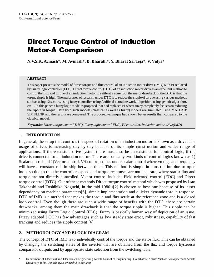
The concept of DTC of IMD is to individually control the torque and the stator flux. This can be obtainedby changing the switching states of the inverter that are obtained from the flux and torque hysteresiscomparator outputs and by appropriate state selection from the switching table.
* Department of Electrical and Electronics Engineering Amrita School of Engineering, Coimbatore Amrita Vishwa Vidyapeetham AmritaUniversity India, Email: [email protected]
I J C T A, 9(15), 2016, pp. 7547-7556© International Science Press
7548 N.V.S.K. Avinash, M. Avinash, B. Bharath, Y. Bharat Sai Teja, V. Vidya
Currents ia, ib are taken from the motors as a feedback and are fed to the torque flux and speed estimatorblock, this block converts these currents into torque and flux parameters which are then compared with thereference torque and reference flux values. The error obtained when reference speed is compared with thecurrent speed, which is fed to a PI controller providing the reference torque. The difference between thereference torque and actual torque as well as the difference between the reference flux and actual flux is fedto the hysteresis controllers (two level for flux and three level for torque), two level hysteresis comparatorgives the output as either 0 or 1 and three level gives the output as 0, 1 or -1 which significally says 1 is toincrease, 0 is to remain the same, -1 is to decrease. So based on various combinations of these values aswitching table as shown in table1 is formed and an appropriate inverter state is selected based on whichsector it is present. (The entire space is divided into six sectors).
2.1. PI and field weakening controllers
The reference torque Te* is obtained as the output from the PI controller by amplifying the error in speed.The flux weakening controller plays active role only if the machine is made run above the rated speed. Sobelow the rated speed the reference flux is taken as constant value and above the rated speed the stator fluxis considered as
* . 10s c
b
r (1)
Where �c is constant flux or the rated flux of the machine and �s* is the reference flux in case if thespeed is above rated speed. ab is the base speed and ar is the rotor speed.
Now the reference flux and the torque obtained from the PI controller are compared with the actual fluxand torque and the errors in them are fed to hysteresis comparators.
In this model a three level hysteresis comparator is used for torque and a two level is used for flux andthe hysteresis comparators are modeled as shown below.
Figure 1: Block diagram of direct torque control
Direct Torque Control of Induction Motor-A Comparison 7549
H� = 1 for E� > + HB�
H� = 1 for E� < – HB�
HTe
= 1 for ETe
> + HBT
HTe
= –1 for ETe
< – HBT
HTe
= 0 for – HBT < E
Te < + HB
T [4]
Where H� is the output of the hysteresis comparator and HTe is the output of the torque hysteresiscomparator, E� is the error in flux and E
Te is error in torque, + HB�,- HB� are the positive and negative
error bands of the flux hysteresis comparator and +HBTe
,-HBTe
are the positive and negative error bands ofthe torque hysteresis comparator.
2.2. Flux, Torque estimation and Sector selection
The line currents of the Stator are sensed for estimating Torque and Flux. The Three Phase parameters areconverted to Two Phase parameters with respect to stationary reference frame by using Clarke’sTransformation for the convenience of computation.
• Clarke’s Transformation
2 / 3 1/ 3 1/ 3qs a b ci i i i (2)
1/ 3 1/ 3ds b ci i i (3)
1/ 3 2 1a bi i
Here, ia, ib, ic are Stator line currents whereas, equations 2 and 3 shows the direct and quadrature axiscurrents where iqs, ids are represented as direct and quadrature axis currents.
v qs = (2/3va – 1/3v
b – 1/3v
c) = 1/3(v
ab + v
ac) (4)
vds
= (-1/ 3vb + 1/ 3v
c) = 1/ 3 v
bc(5)
The direct and quadrature components voltage are calculated using equations 4,5 where va, vb and vcare Stator phase voltages whereas, vqs is the quadrature axis phase voltage and vds is the direct axis phasevoltages.
• Flux estimation
The Flux along direct and quadrature axis are estimated by
ds ds dsV Ri dt (6)
qs qs qsV Ri dt (7)
2 2s ds qs (8)
�s represents the resultant stator flux linkage per phase.
• Torque estimation
From the above obtained Direct and quadrature axis flux and currents, The Electromagnetic torque isestimated by
Te = (3/2).(p/2). (�
ds - i
qs – �
qs i
ds) (9)

7550 N.V.S.K. Avinash, M. Avinash, B. Bharath, Y. Bharat Sai Teja, V. Vidya
Here, P/2 represents number of pole pairs in Induction motor.
• Sector selection
The angle between the resultant Flux linkage and reference axis is given by
1 qs
ds
a Tan (10)
The � value estimated is used for selecting the sector in which resultant flux linkage lies.
2.3. Switching table
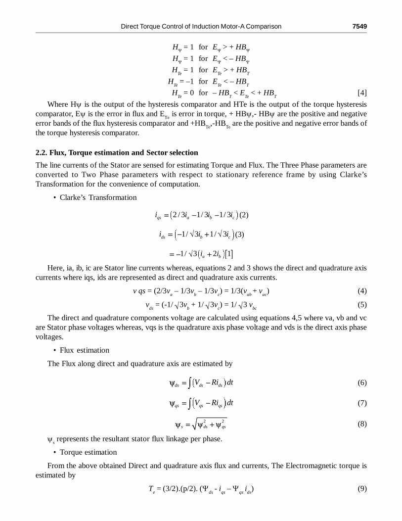
Based on various combinations of the outputs of these hysteresis comparators a switching table is formed.The reference Torque and reference Flux can be achieved by selecting the suitable Switching states fromthe following table1.
Here, the division of the six sectors is shown as below
Figure 2: Division of six sectors.
• Effect on Flux
The resultant stator flux from a time period 0 to T is given by
0 . 0.
T
s s sv T i R dt (11)
Here, the stator resistance voltage drop is negligble due to its small value.
Where, �0 is the starting value of flux at time = 0.
The rate of change of Flux with respect to time is
sd
dt(12)
Direct Torque Control of Induction Motor-A Comparison 7551
.s sv T (13)
Therefore, the Flux is proportional to the magnitude of Vs.
• Effect on Torque
The electromagnetic Torque of an Induction motor depends on stator flux, rotor flux and relative position�, which is given by
3sin
2 2m
e s rr
LpT
L (14)
Table 1optimum voltage vector switching table.
3. FUZZY LOGIC CONTROL
Fuzzy is the control logic made in accordance with human’s natural way of interpretation. The rules set offuzzy are made based on various predictive ability of the humans. In case of PI controller it is very difficult topredict the exact value of kp and ki. Thus unexpected changes in the load conditions would produce overshoot,high ripple in torque, oscillation of the IMD, etc...[4]. This problem can be rendered by forming a fuzzy ruletable as fuzzy does not require any details of kp and ki values and its response time is better than the PIcontroller. Mamdani type of fuzzy logic control is used in this model and the method used for De-fuzzificationprocess is ‘Centroid’. Fuzzification process involves these following stages as shown below
1) Two fuzzy input sets and one fuzzy output set for which each set will consists of seven subsets.
2) Fuzzification process using continuous class containing all entities referred to an argument.
3) Mamdani’s minimum operator is used for implication.
4) The method used for Defuzzification process is centroid.
Fuzzification process is used to modify the numerical variable into linguistic variable also known asfuzzy number. The second stage De-fuzzification process is used for providing a computable fuzzy logicresult for the provided fuzzy sets and membership degrees corresponding to it.
Data Base: The database stores the definition of the membership Function required by fuzzifier anddefuzzifier [2].

7552 N.V.S.K. Avinash, M. Avinash, B. Bharath, Y. Bharat Sai Teja, V. Vidya
The following seven fuzzy sets are used for converting numerical values to linguistic values and theirranges are represented in fig.3.NB-Negative big, NM-Negative medium, NS-Negative small, ZE-Zero error,PS-Positive small, PM-Positive medium, PB-Positive big.
3.1. Fuzzy Variables
The speed error and the rate of speed error are considered as the input variables and are indentified usingthe state of membership functions in the provided fuzzy set. Triangular functions are used for defining thisparticular fuzzy sets.
3.2. Rules for Fuzzy control
This paper consists of two input variables each comprise of seven linguistic values, hence, overall 7*7 = 49rules are obtained as shown in the table 2.
Figure 3: The fuzzy membership functions of input variables(a) speed error, (b) rate of speed error, and (c) output variable.
Direct Torque Control of Induction Motor-A Comparison 7553
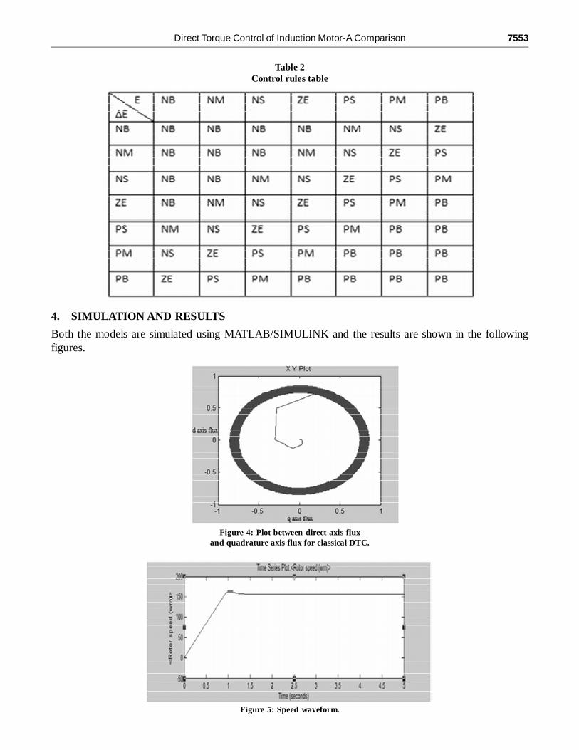
4. SIMULATION AND RESULTS
Both the models are simulated using MATLAB/SIMULINK and the results are shown in the followingfigures.
Table 2Control rules table
Figure 4: Plot between direct axis fluxand quadrature axis flux for classical DTC.
Figure 5: Speed waveform.
7554 N.V.S.K. Avinash, M. Avinash, B. Bharath, Y. Bharat Sai Teja, V. Vidya
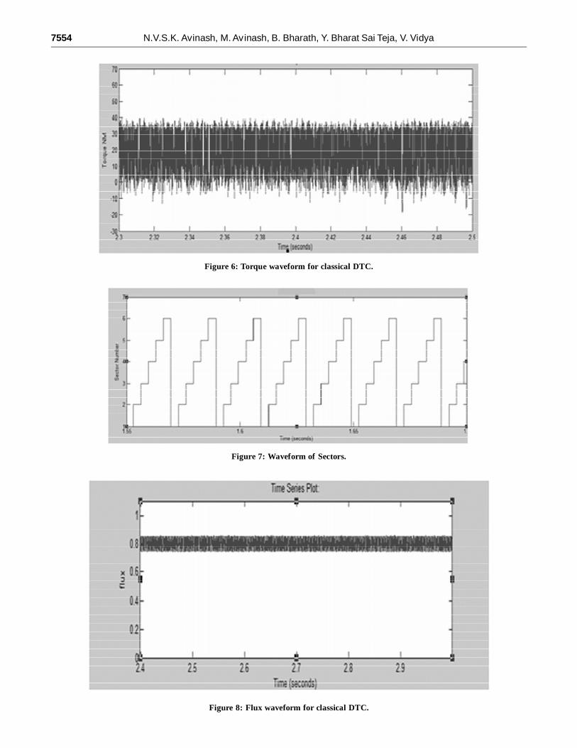
Figure 8: Flux waveform for classical DTC.
Figure 7: Waveform of Sectors.
Figure 6: Torque waveform for classical DTC.
Direct Torque Control of Induction Motor-A Comparison 7555
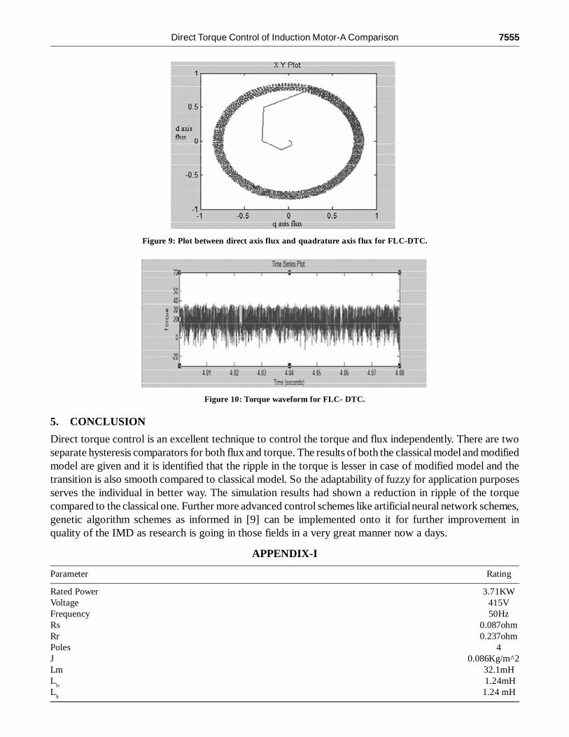
Figure 9: Plot between direct axis flux and quadrature axis flux for FLC-DTC.
Figure 10: Torque waveform for FLC- DTC.
5. CONCLUSION
Direct torque control is an excellent technique to control the torque and flux independently. There are twoseparate hysteresis comparators for both flux and torque. The results of both the classical model and modifiedmodel are given and it is identified that the ripple in the torque is lesser in case of modified model and thetransition is also smooth compared to classical model. So the adaptability of fuzzy for application purposesserves the individual in better way. The simulation results had shown a reduction in ripple of the torquecompared to the classical one. Further more advanced control schemes like artificial neural network schemes,genetic algorithm schemes as informed in [9] can be implemented onto it for further improvement inquality of the IMD as research is going in those fields in a very great manner now a days.
APPENDIX-I
Parameter Rating
Rated Power 3.71KWVoltage 415VFrequency 50HzRs 0.087ohmRr 0.237ohmPoles 4J 0.086Kg/m^2Lm 32.1mHL
ls 1.24mH
Llr
1.24 mH
7556 N.V.S.K. Avinash, M. Avinash, B. Bharath, Y. Bharat Sai Teja, V. Vidya
The induction motor parameters used are as shown below.
REFERENCES[1] B.K. Bose, “Modern Power Electronics and AC Drives”. Upper Saddle River, NJ: Prentice Hall, 2002,pp 388-400 and
pp 408-413.
[2] “Direct Flux and torque control of three phase induction motor drive using PI and fuzzy logic controllers for speedregulator and low torque ripple”, IEEE Allahabad, Uttarpradesh,16-18 March 2012, pp 1-8.
[3] A. Miloudi, E.A. Alradadi, A. Draou, “A new control strategy of direct torque fuzzy control of a PWM inverter fedinduction motor drive,” IEEE ISIE 2006, July 9-12, 2016.
[4] R. Jones Samuel, “Speed Regulation and Torque Ripple Minimization of Induction Motor by DTC with PI and FuzzyLogic Controller,” Int. Journal of Engineering Research and Applications ISSN: 2248-9622, Vol. 4, Issue 4 (version 1),April14, pp. 61-66.
[5] Y. S. Lai and J. H. Chen, “A new approach to direct torque control of induction motor drives for constant inverterswitching frequency and torque ripple reduction,” IEEE Trans. Energy Conv., vol. 16, pp. 220–227, Sept. 2001.
[6] Yen-Shin Lai, Juo-Chiun Lin, “New Hybrid Fuzzy Controller for Direct Torque Control Induction Motor Drives,” IEEETransactions on power electronics, vol. 18, no. 5, September 2003, pp 1211-1219.
[7] Jiang Zhijun, Hu Shimiao, Cao Wenhui, “A new fuzzy logic torque control scheme based on vedctor control and directtorque control for Induction machine,” The 3rd International conference on innovative computing information, 2008.
[8] R .Krishnan, “Electric motor drives-Modeling,Analysis, and Control,” Virginia Tech, Blacksburg, VA,2001.
[9] Hao Li,Qium Mo, Zhilin Zhao, “Research on direct torque control of induction motor based on genetic algorithm andfuzzy based PI controller.
[10] T. Prabu, S. Sampathkumar, R. Gunabalan, “Advanced Direct Torque Control of Induction motor,” IEEE Coimbatore,20-22 July 2011, pp. 1-6.