Embed Size (px)
Citation preview
Innovative Systems Design and Engineering www.iiste.org
ISSN 2222-1727 (Paper) ISSN 2222-2871 (Online)
Vol 2, No 4, 2011
283
Direct Torque Control Algorithm for Induction Motor Drives
for the Mitigation of Common Mode Voltage
V. Anantha Lakshmi
Department of Electrical and Electronics Engineering, G.Pulla Reddy Engineering College
Kurnool-518007, Andhra Pradesh. India.
E-mail: [email protected]
V.C.Veera Reddy
Department of Electrical and Electronics Engineering, S.V. University,
Tirupati, Andhra Pradesh, India
E-mail: [email protected]
M.Surya Kalavathi
Department of Electrical and Electronics Engineering, J.N.T.U
Hyderabad, Andhra Pradesh, India
E-mail: [email protected]
Abstract
This paper presents a novel direct torque control (DTC) algorithm for induction motor drives for the
reduction of common mode voltage. In the Proposed DTC algorithm-I the space vector plane is divided into
six sectors same as that of Conventional DTC algorithm. In the proposed algorithm-II, the space vector
plane is divided into twelve sectors instead of six sectors as in conventional DTC algorithm and Proposed
DTC algorithm-I. Moreover, the proposed algorithm does not use the zero voltage vectors. To validate the
proposed algorithm, numerical simulations have been carried out using MATLAB-Simulink and results are
presented and compared. From the simulation results it can be observed the proposed algorithm reduces the
common mode voltage variations compared to conventional DTC algorithm with slightly increased ripples
in current, torque and flux.
Keywords: Common mode voltage, direct torque control, induction motor drives, look-up table, voltage
vectors
1. Introduction
Nowadays the induction motors are popular in the industry because of their advantages. The high
performance control algorithms that are used for induction motor drives are field oriented control (FOC) or
vector control and direct torque control (DTC) or direct self control (DSC) (2002). F. Blaschke (1972)
propsed FOC which permits independent control of the torque and flux by decoupling stator current into
two orthogonal components. In contrast, Werner Leonard (2003), Isao Takahashi and Toshihiko
Noguchi(1986) and M. Depenbrock (1988) proposed DTC which is simple, robust to parameter variations;
do not require any co-ordinate transformations . James N. Nash (1997) proposed DTC that abandons the
stator current control philosophy and achieves bang-bang torque and flux control by directly modifying the
stator voltage in accordance with the torque and flux errors. The basic concept of DTC is to control both
electromagnetic torque and stator flux simultaneously by proper selection of optimum inverter switching
states in accordance with the torque and flux errors.
Innovative Systems Design and Engineering www.iiste.org
ISSN 2222-1727 (Paper) ISSN 2222-2871 (Online)
Vol 2, No 4, 2011
284
In spite of its simplicity, DTC generates high level common mode voltage variations. To avoid the
problems of common mode voltage variations a new DTC algorithm has developed by Maurizio
Cirrincione, Marcello Pucci, Gianpaolo Vitale and Giansalvo Cirrincione (2006) by using only even or only
odd voltage vectors in every sector. However, this method gives torque ambiguity. To overcome the torque
ambiguity, modified DTC algorithm and 12-sector based DTC algorithms have been proposed by Y.V.Siva
Reddy, M.Vijayakumar and T. Brahmananda Reddy (2007). This paper presents a novel direct torque
control algorithms for reduced common mode voltage variations. In the proposed DTC two algorithms are
considered. In the proposed algorithm-I, a six sector based DTC is considered same as in CDTC without
using zero voltage vectors. In proposed algorithm-II, 12-sector based DTC algorithm is considered where
the first sector zone is from 00 to 30
0.
1.1 Principle of Conventional DTC
The electromagnetic torque produced by the induction motor in stationary reference frame can be
expressed as given in (1).
sin22
3sr
rLsL
mLPeT (1)
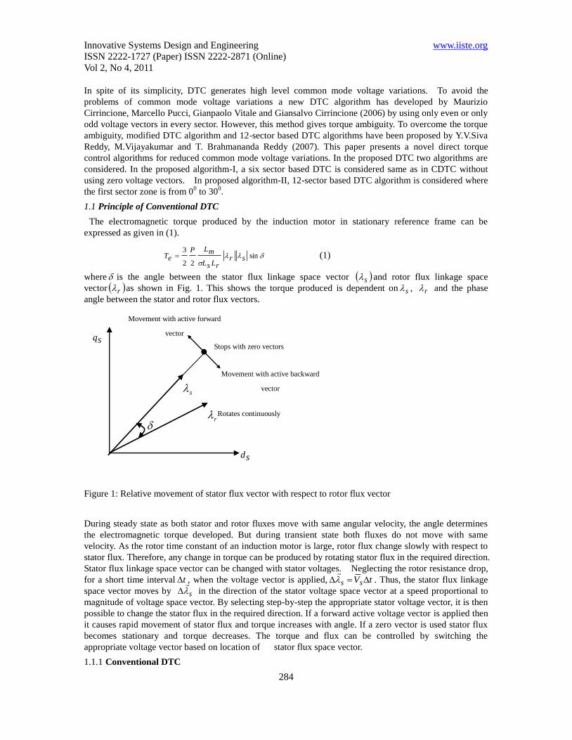
where is the angle between the stator flux linkage space vector s and rotor flux linkage space
vector r as shown in Fig. 1. This shows the torque produced is dependent on s , r and the phase
angle between the stator and rotor flux vectors.
Figure 1: Relative movement of stator flux vector with respect to rotor flux vector
During steady state as both stator and rotor fluxes move with same angular velocity, the angle determines
the electromagnetic torque developed. But during transient state both fluxes do not move with same
velocity. As the rotor time constant of an induction motor is large, rotor flux change slowly with respect to
stator flux. Therefore, any change in torque can be produced by rotating stator flux in the required direction.
Stator flux linkage space vector can be changed with stator voltages. Neglecting the rotor resistance drop,
for a short time interval t , when the voltage vector is applied, tVss
. Thus, the stator flux linkage
space vector moves by s
in the direction of the stator voltage space vector at a speed proportional to
magnitude of voltage space vector. By selecting step-by-step the appropriate stator voltage vector, it is then
possible to change the stator flux in the required direction. If a forward active voltage vector is applied then
it causes rapid movement of stator flux and torque increases with angle. If a zero vector is used stator flux
becomes stationary and torque decreases. The torque and flux can be controlled by switching the
appropriate voltage vector based on location of stator flux space vector.
1.1.1 Conventional DTC
r
s
sd
sq
Movement with active forward
vector
Movement with active backward
vector
Stops with zero vectors
Rotates continuously
Innovative Systems Design and Engineering www.iiste.org
ISSN 2222-1727 (Paper) ISSN 2222-2871 (Online)
Vol 2, No 4, 2011
285
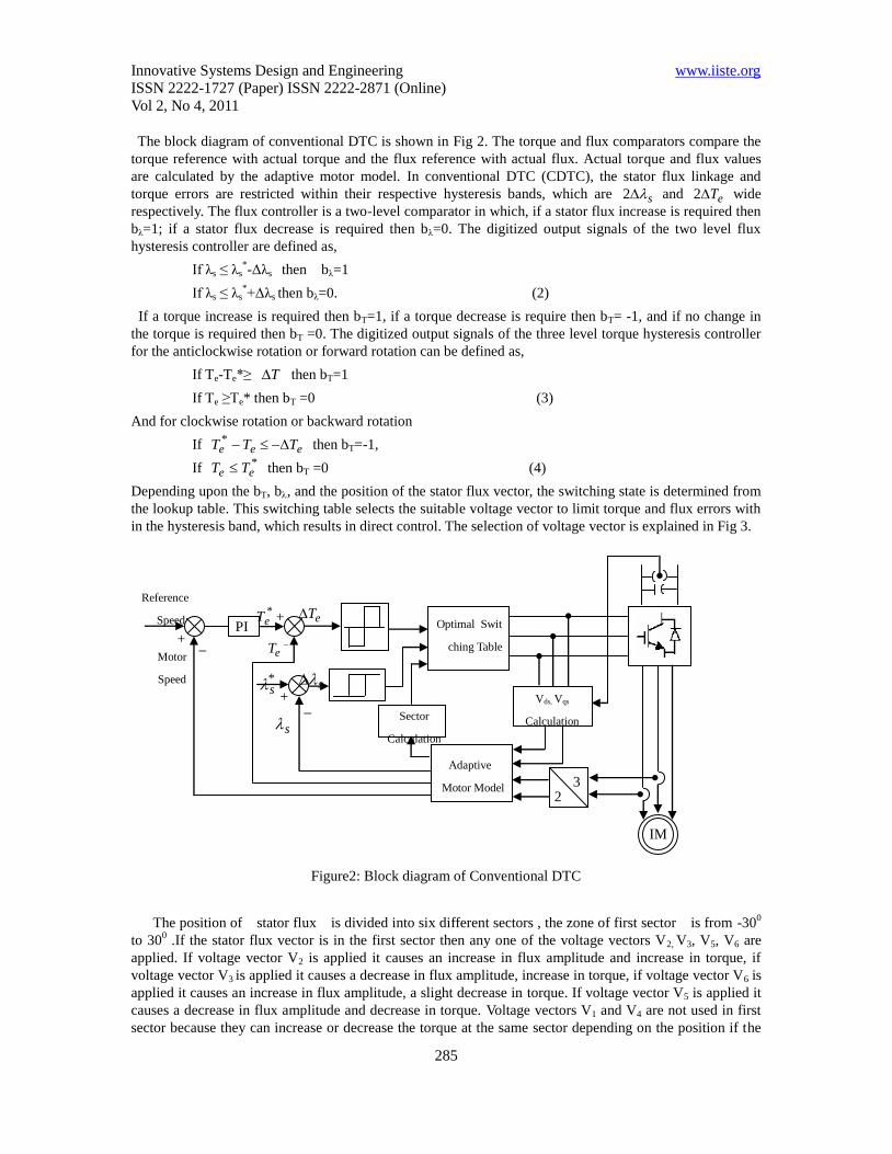
The block diagram of conventional DTC is shown in Fig 2. The torque and flux comparators compare the
torque reference with actual torque and the flux reference with actual flux. Actual torque and flux values
are calculated by the adaptive motor model. In conventional DTC (CDTC), the stator flux linkage and
torque errors are restricted within their respective hysteresis bands, which are s2 and eT2 wide
respectively. The flux controller is a two-level comparator in which, if a stator flux increase is required then
bλ=1; if a stator flux decrease is required then bλ=0. The digitized output signals of the two level flux
hysteresis controller are defined as,
If λs ≤ λs*-Δλs then bλ=1
If λs ≤ λs*+Δλs then bλ=0. (2)
If a torque increase is required then bT=1, if a torque decrease is require then bT= -1, and if no change in
the torque is required then bT =0. The digitized output signals of the three level torque hysteresis controller
for the anticlockwise rotation or forward rotation can be defined as,
If Te-Te*≥ T then bT=1
If Te ≥Te* then bT =0 (3)
And for clockwise rotation or backward rotation
If eee TTT * then bT=-1,
If *ee TT then bT =0 (4)
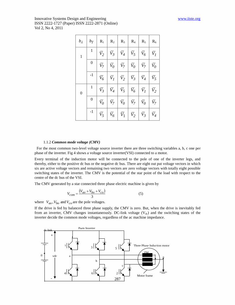
Depending upon the bT, b, and the position of the stator flux vector, the switching state is determined from
the lookup table. This switching table selects the suitable voltage vector to limit torque and flux errors with
in the hysteresis band, which results in direct control. The selection of voltage vector is explained in Fig 3.
Figure2: Block diagram of Conventional DTC
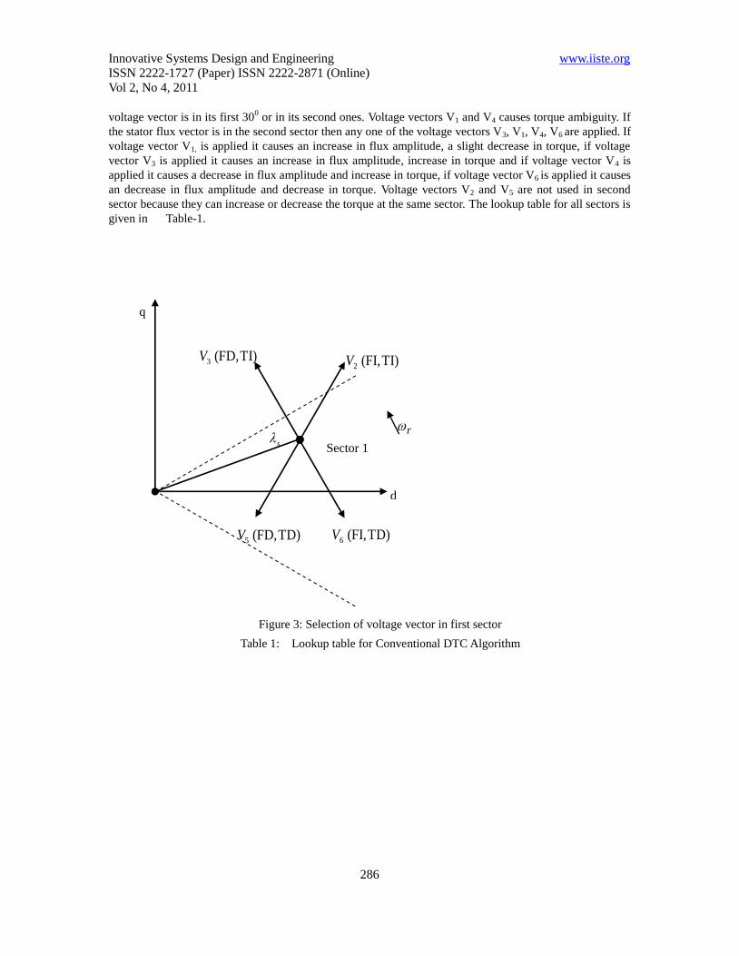
The position of stator flux is divided into six different sectors , the zone of first sector is from -300
to 300 .If the stator flux vector is in the first sector then any one of the voltage vectors V2, V3, V5, V6 are
applied. If voltage vector V2 is applied it causes an increase in flux amplitude and increase in torque, if
voltage vector V3 is applied it causes a decrease in flux amplitude, increase in torque, if voltage vector V6 is
applied it causes an increase in flux amplitude, a slight decrease in torque. If voltage vector V5 is applied it
causes a decrease in flux amplitude and decrease in torque. Voltage vectors V1 and V4 are not used in first
sector because they can increase or decrease the torque at the same sector depending on the position if the
Adaptive
Motor Model 3 2
IM
PI + _ _
_
+
+
*eT
*s
eT
s
s
eT Optimal Swit
ching Table
Sector
Calculation
Vds, Vqs
Calculation
Reference
Speed
Motor
Speed
Innovative Systems Design and Engineering www.iiste.org
ISSN 2222-1727 (Paper) ISSN 2222-2871 (Online)
Vol 2, No 4, 2011
286
voltage vector is in its first 300 or in its second ones. Voltage vectors V1 and V4 causes torque ambiguity. If
the stator flux vector is in the second sector then any one of the voltage vectors V3, V1, V4, V6 are applied. If
voltage vector V1, is applied it causes an increase in flux amplitude, a slight decrease in torque, if voltage
vector V3 is applied it causes an increase in flux amplitude, increase in torque and if voltage vector V4 is
applied it causes a decrease in flux amplitude and increase in torque, if voltage vector V6 is applied it causes
an decrease in flux amplitude and decrease in torque. Voltage vectors V2 and V5 are not used in second
sector because they can increase or decrease the torque at the same sector. The lookup table for all sectors is
given in Table-1.
Figure 3: Selection of voltage vector in first sector
Table 1: Lookup table for Conventional DTC Algorithm
Sector 1
d
q
s
TI) (FI, 2V TI) (FD, 3V
TD) (FD, 5V TD) (FI, 6V
r
Innovative Systems Design and Engineering www.iiste.org
ISSN 2222-1727 (Paper) ISSN 2222-2871 (Online)
Vol 2, No 4, 2011
287
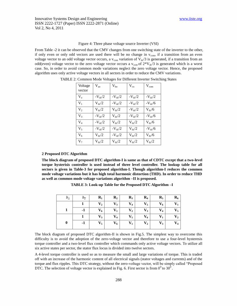
1.1.2 Common mode voltage (CMV)
For the most common two-level voltage source inverter there are three switching variables a, b, c one per
phase of the inverter. Fig 4 shows a voltage source inverter(VSI) connected to a motor.
Every terminal of the induction motor will be connected to the pole of one of the inverter legs, and
thereby, either to the positive dc bus or the negative dc bus. There are eight out put voltage vectors in which
six are active voltage vectors and remaining two vectors are zero voltage vectors with totally eight possible
switching states of the inverter. The CMV is the potential of the star point of the load with respect to the
centre of the dc bus of the VSI.
The CMV generated by a star connected three phase electric machine is given by
3
coboaocom
VVVV
(5)
where coboao VVV and , are the pole voltages.
If the drive is fed by balanced three phase supply, the CMV is zero. But, when the drive is inevitably fed
from an inverter, CMV changes instantaneously. DC-link voltage (Vdc) and the switching states of the
inverter decide the common mode voltages, regardless of the ac machine impedance.
b Tb R1 R2 R3 R4 R5 R6
1
1 2V 3V 4V 5V 6V 1V
0 7V 0V 7V 0V 7V 0V
-1 6V 1V 2V 3V 4V 5V
0
1 3V 4V 5V 6V 1V 2V
0 0V 7V 0V 7V 0V 7V
-1 5V 6V 1V 2V 3V 4V
+
-
a
1
4
3
2
5
6
n
dc link
vdc 0
Pwm Inverter
b
Three Phase Induction motor
ZM
Motor frame
c
Innovative Systems Design and Engineering www.iiste.org
ISSN 2222-1727 (Paper) ISSN 2222-2871 (Online)
Vol 2, No 4, 2011
288
Figure 4: Three phase voltage source Inverter (VSI)
From Table -2 it can be observed that the CMV changes from one switching state of the inverter to the other,
if only even or only odd vectors are used there will be no change in vcom, if a transition from an even
voltage vector to an odd voltage vector occurs, a vcom variation of Vdc/3 is generated, if a transition from an
odd(even) voltage vector to the zero voltage vector occurs a vcom of 2*Vdc/3 is generated which is a worst
case. So, in order to avoid common mode variations neglect the zero voltage vector. Hence, the proposed
algorithm uses only active voltage vectors in all sectors in order to reduce the CMV variations.
TABLE 2: Common Mode Voltages for Different Inverter Switching States
Voltage
vector
Vao Vbo Vco Vcom
Vo -Vdc/2 -Vdc/2 -Vdc/2 -Vdc/2
V1 Vdc/2 -Vdc/2 -Vdc/2 -Vdc/6
V2 Vdc/2 Vdc/2 -Vdc/2 Vdc/6
V3 -Vdc/2 Vdc/2 -Vdc/2 -Vdc/6
V4 -Vdc/2 Vdc/2 Vdc/2 Vdc/6
V5 -Vdc/2 -Vdc/2 Vdc/2 -Vdc/6
V6 Vdc/2 -Vdc/2 Vdc/2 Vdc/6
V7 Vdc/2 Vdc/2 Vdc/2 Vdc/2
2 Proposed DTC Algorithm
The block diagram of proposed DTC algorithm-I is same as that of CDTC except that a two-level
torque hysterisis controller is used instead of three level controller. The lookup table for all
sectors is given in Table-3 for proposed algorithm-I. Though algorithm-I reduces the common
mode voltage variations but it has high total harmonic distortion (THD). In order to reduce THD
as well as common mode voltage variations algorithm –II is proposed.
TABLE 3: Look-up Table for the Proposed DTC Algorithm –I
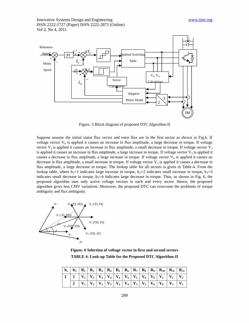
The block diagram of proposed DTC algorithm-II is shown in Fig.5. The simplest way to overcome this
difficulty is to avoid the adoption of the zero-voltage vector and therefore to use a four-level hysteresis
torque controller and a two-level flux controller which commands only active voltage vectors. To utilize all
six active states per sector, the stator flux locus is divided into twelve sectors.
A 4-level torque controller is used so as to measure the small and large variations of torque. This is traded
off with an increase of the harmonic content of all electrical signals (stator voltages and currents) and of the
torque and flux ripples. This DTC strategy, without the zero-voltage vector, will be simply called “Proposed
DTC. The selection of voltage vector is explained in Fig. 6. First sector is from 00 to 30
0 .
b Tb R1 R2 R3 R4 R5 R6
1
1 V2 V3 V4 V5 V6 V1
-1 V6 V1 V2 V3 V4 V5
0
1 V3 V4 V5 V6 V1 V2
-1 V5 V6 V1 V2 V3 V4
Innovative Systems Design and Engineering www.iiste.org
ISSN 2222-1727 (Paper) ISSN 2222-2871 (Online)
Vol 2, No 4, 2011
289
Figure. 5 Block diagram of proposed DTC Algorithm-II
Suppose assume the initial stator flux vector and rotor flux are in the first sector as shown in Fig.6. If
voltage vector V6 is applied it causes an increase in flux amplitude, a large decrease in torque. If voltage
vector V1 is applied it causes an increase in flux amplitude, a small decrease in torque. If voltage vector V2
is applied it causes an increase in flux amplitude, a large increase in torque. If voltage vector V3 is applied it
causes a decrease in flux amplitude, a large increase in torque. If voltage vector V4 is applied it causes an
decrease in flux amplitude, a small increase in torque. If voltage vector V5 is applied it causes a decrease in
flux amplitude, a large decrease in torque. The lookup table for all sectors is given in Table-4. From the
lookup table, where bT=1 indicates large increase in torque, bT=2 indicates small increase in torque, bT=3
indicates small decrease in torque, bT=4 indicates large decrease in torque. Thus, as shown in Fig. 6, the
proposed algorithm uses only active voltage vectors in each and every sector. Hence, the proposed
algorithm gives less CMV variations. Moreover, the proposed DTC can overcome the problems of torque
ambiguity and flux ambiguity.
Figure. 6 Selection of voltage vector in first and second sectors
TABLE 4: Look-up Table for the Proposed DTC Algorithm-II
bλ bT R1 R2 R3 R4 R5 R6 R7 R8 R9 R10 R11 R12
1 1 V2 V3 V3 V4 V4 V5 V5 V6 V6 V1 V1 V2
2 V2 V2 V3 V3 V4 V4 V5 V5 V6 V6 V1 V1
V1
V3 (TI, FD)
V5 (TD, FD) s
r
V6 (TD, FI)
V4 (TI, FD)
I
V2 (TI, FI)
V1 (TD, FI)
V2
Adaptive
Motor Model 3 2
IM
PI + _ _
_
+
+
*eT
s
eT
s
s
eT
Optimal Switching
Table
Sector
Calculation
Vds, Vqs
Calculation
Reference
Speed
Motor
Speed
Innovative Systems Design and Engineering www.iiste.org
ISSN 2222-1727 (Paper) ISSN 2222-2871 (Online)
Vol 2, No 4, 2011
290
3 V1 V1 V2 V2 V3 V3 V4 V4 V5 V5 V6 V6
4 V6 V1 V1 V2 V2 V3 V3 V4 V4 V5 V5 V6
0 1 V3 V4 V4 V5 V5 V6 V6 V1 V1 V2 V2 V3
2 V4 V4 V5 V5 V6 V6 V1 V1 V2 V2 V3 V3
3 V5 V5 V6 V6 V1 V1 V2 V2 V3 V3 V4 V4
4 V5 V6 V6 V1 V1 V2 V2 V3 V3 V4 V4 V5
3. Results and Discussion
To validate the proposed method, a numerical simulation has been carried out by using
Matlab/Simulink. For the simulation, the reference flux is taken as 1wb and starting torque is limited
to 45 N-m. For the simulation studies, a 3-phase, 400V, 4 kW, 4-pole, 50 Hz, 1470 rpm Squirrel cage
induction motor has considered. The parameters of the given induction motor are as follows:
Rs=1.57ohm, Rr=1.21ohm, Lm= 0.165H, Ls= 0.17H, Lr= 0.17 H and J= 0.089 Kg - m2. For the
simulation, PI in proposed diagram algorithm was designed based on trail and error method.
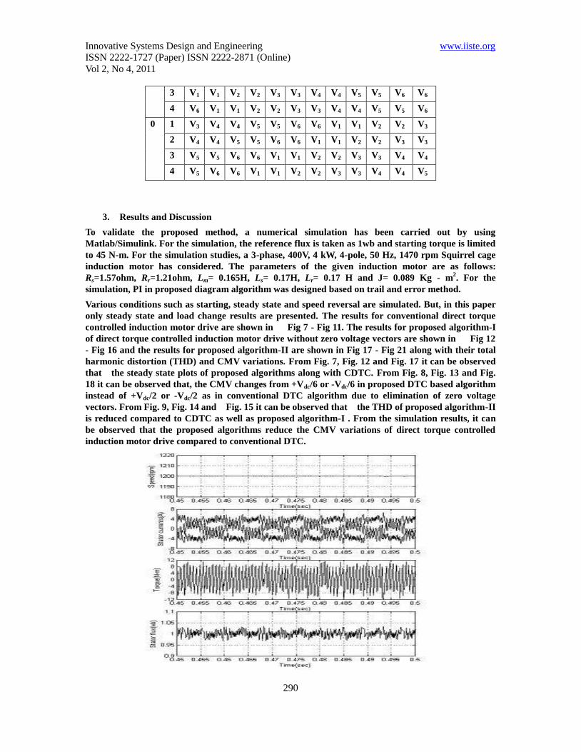
Various conditions such as starting, steady state and speed reversal are simulated. But, in this paper
only steady state and load change results are presented. The results for conventional direct torque
controlled induction motor drive are shown in Fig 7 - Fig 11. The results for proposed algorithm-I
of direct torque controlled induction motor drive without zero voltage vectors are shown in Fig 12
- Fig 16 and the results for proposed algorithm-II are shown in Fig 17 - Fig 21 along with their total
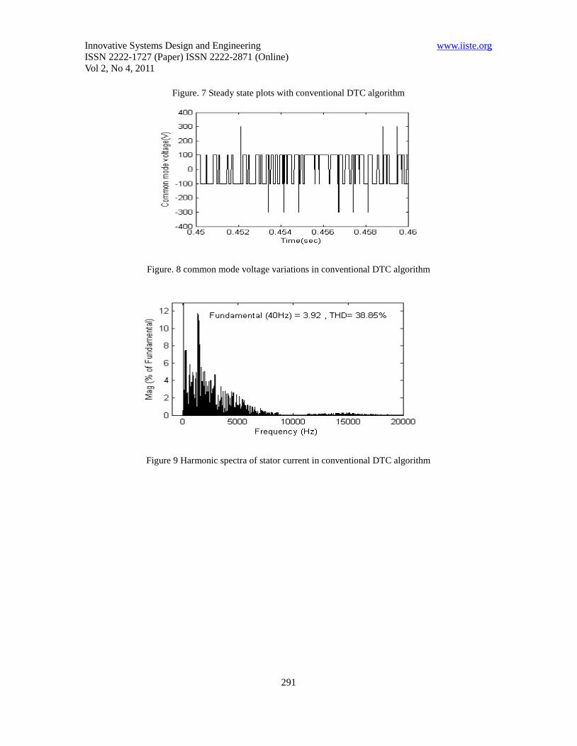
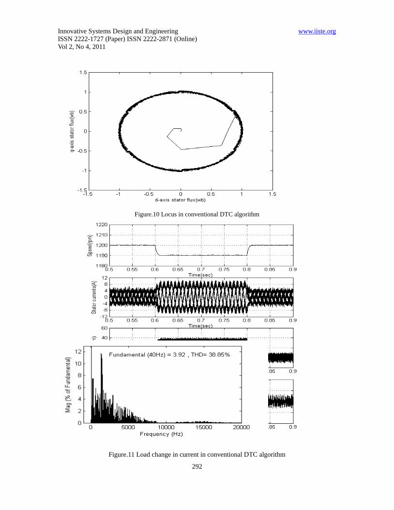
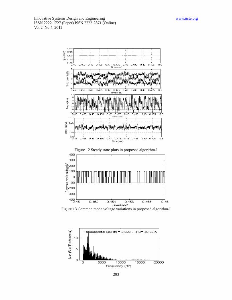
harmonic distortion (THD) and CMV variations. From Fig. 7, Fig. 12 and Fig. 17 it can be observed
that the steady state plots of proposed algorithms along with CDTC. From Fig. 8, Fig. 13 and Fig.
18 it can be observed that, the CMV changes from +Vdc/6 or -Vdc/6 in proposed DTC based algorithm
instead of +Vdc/2 or -Vdc/2 as in conventional DTC algorithm due to elimination of zero voltage
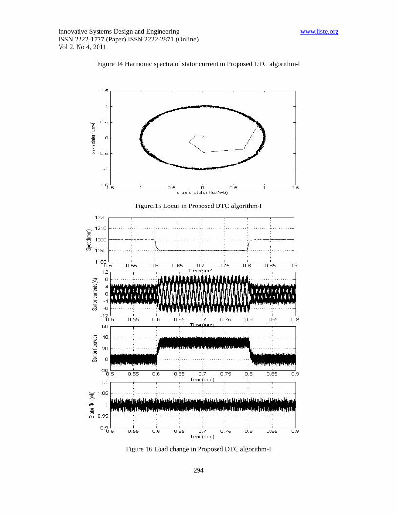
vectors. From Fig. 9, Fig. 14 and Fig. 15 it can be observed that the THD of proposed algorithm-II
is reduced compared to CDTC as well as proposed algorithm-I . From the simulation results, it can
be observed that the proposed algorithms reduce the CMV variations of direct torque controlled
induction motor drive compared to conventional DTC.
Innovative Systems Design and Engineering www.iiste.org
ISSN 2222-1727 (Paper) ISSN 2222-2871 (Online)
Vol 2, No 4, 2011
291
Figure. 7 Steady state plots with conventional DTC algorithm
Figure. 8 common mode voltage variations in conventional DTC algorithm
Figure 9 Harmonic spectra of stator current in conventional DTC algorithm
Innovative Systems Design and Engineering www.iiste.org
ISSN 2222-1727 (Paper) ISSN 2222-2871 (Online)
Vol 2, No 4, 2011
292
Figure.10 Locus in conventional DTC algorithm
Figure.11 Load change in current in conventional DTC algorithm
Innovative Systems Design and Engineering www.iiste.org
ISSN 2222-1727 (Paper) ISSN 2222-2871 (Online)
Vol 2, No 4, 2011
293
Figure 12 Steady state plots in proposed algorithm-I
Figure 13 Common mode voltage variations in proposed algorithm-I
Innovative Systems Design and Engineering www.iiste.org
ISSN 2222-1727 (Paper) ISSN 2222-2871 (Online)
Vol 2, No 4, 2011
294
Figure 14 Harmonic spectra of stator current in Proposed DTC algorithm-I
Figure.15 Locus in Proposed DTC algorithm-I
Figure 16 Load change in Proposed DTC algorithm-I

Innovative Systems Design and Engineering www.iiste.org
ISSN 2222-1727 (Paper) ISSN 2222-2871 (Online)
Vol 2, No 4, 2011
295
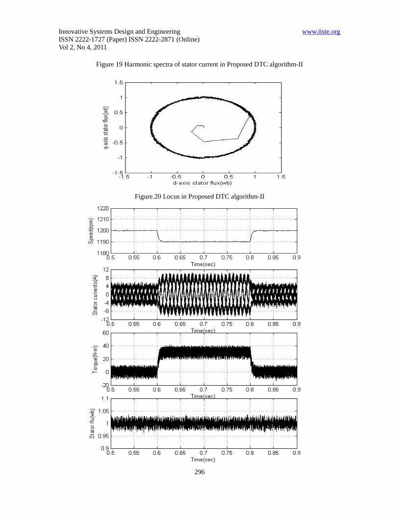
Figure 17 Steady state plots in proposed algorithm-II
Figure 18 Common mode voltage variations in proposed algorithm-II
Innovative Systems Design and Engineering www.iiste.org
ISSN 2222-1727 (Paper) ISSN 2222-2871 (Online)
Vol 2, No 4, 2011
296
Figure 19 Harmonic spectra of stator current in Proposed DTC algorithm-II
Figure.20 Locus in Proposed DTC algorithm-II

Innovative Systems Design and Engineering www.iiste.org
ISSN 2222-1727 (Paper) ISSN 2222-2871 (Online)
Vol 2, No 4, 2011
297
Figure.21 Load change in Proposed DTC algorithm-I
4. Conclusion
In conventional DTC CMV variations are very high because of zero voltage vectors. To reduce the CMV
variations, a novel DTC algorithm has proposed in this paper. Proposed DTC algorithm-I is same as that of
CDTC except that usage of zero voltage vectors are avoided. Though the Proposed DTC algorithm-I
reduces the CMV variations its THD is high compared with CDTC. So, in order to reduce THD as well as
CMV variations algorithm-II is proposed for DTC. In the proposed algorithm-II, all the six active voltage
vectors are used in each sector. Thus, by eliminating the zero voltage vectors, the CMV variations are
reduced and also the total THD of stator current is reduced compared with CDTC and proposed
algorithm-I. From the simulation results, it can be observed that the CMV is very less in the proposed
algorithm compared to conventional DTC algorithm.
5. References
C. Domenico Casadei, Francesco Profumo, Giovanni Serra, and Angelo Tani,(2002), “FOC and DTC: Two
Viable Schemes for Induction Motors Torque Control”,IEEE Trans. Power Electron., vol. 17, no.5, pp.
779-787.
F. Blaschke(1972), “The principle of field orientation as applied to the new transvector closed loop control
system for rotating-field machines," Siemens Re view, pp 217-220.
Werner Leonard (2003), “Control of electrical drives” Springer-Verlag, Third Edition.
Isao Takahashi and Toshihiko Noguchi (1986), “A new quick-response and high- efficiency control
strategy of an induction motor,” IEEE Trans.Ind. Applicat., vol. IA-22, no.5, pp. 820-827.
M. Depenbrock(1988), "Direct-self control (DSC) of inverter-fed induction machine," IEEE Trans. Power
Electron., vol. 3, no. 4, pp. 420-429.
James N. Nash (1997), “Direct Torque Control, Induction Motor Vector Control with out an Encoder”
IEEE Trans. Ind. Applicat., vol. 33, no. 2, Mar/Apr 1997, pp.333-34a,
Maurizio Cirrincione, Marcello Pucci, Gianpaolo Vitale and Giansalvo Cirrincione(2006), “A new direct
torque control strategy for the minimization of com mon-mode emissions” IEEE Trans. Ind. Appl.,vol.4,
no.2.
Y.V.Siva Reddy, M.Vijayakumar and T. Brahmananda Reddy (2007), “Direct Torque Control of Induction
Motor Using Sophisticated Lookup Tables Based on Neural Networks AIML Journal, Volume (7), Issue (1).

This academic article was published by The International Institute for Science,
Technology and Education (IISTE). The IISTE is a pioneer in the Open Access
Publishing service based in the U.S. and Europe. The aim of the institute is
Accelerating Global Knowledge Sharing.
More information about the publisher can be found in the IISTE’s homepage:
http://www.iiste.org
The IISTE is currently hosting more than 30 peer-reviewed academic journals and
collaborating with academic institutions around the world. Prospective authors of
IISTE journals can find the submission instruction on the following page:
http://www.iiste.org/Journals/
The IISTE editorial team promises to the review and publish all the qualified
submissions in a fast manner. All the journals articles are available online to the
readers all over the world without financial, legal, or technical barriers other than
those inseparable from gaining access to the internet itself. Printed version of the
journals is also available upon request of readers and authors.
IISTE Knowledge Sharing Partners
EBSCO, Index Copernicus, Ulrich's Periodicals Directory, JournalTOCS, PKP Open
Archives Harvester, Bielefeld Academic Search Engine, Elektronische
Zeitschriftenbibliothek EZB, Open J-Gate, OCLC WorldCat, Universe Digtial
Library , NewJour, Google Scholar