Embed Size (px)
Citation preview

A-dec 500P R E - I N S T A L L A T I O N G U I D E
A-dec 511 Chair with 532 System A-dec 511 Chair with A-dec 333 Radius®-Style System
This document contains technical specifications for installing the A-dec 511 chair and associated systems.
Contents
Structural Requirements . . . . . . . . . . . . . . . . . . . . . . . . . . . . . . . . . . . . . . . . . . . . . . . . . . . 2Utility Requirements . . . . . . . . . . . . . . . . . . . . . . . . . . . . . . . . . . . . . . . . . . . . . . . . . . . . . 2Shipping Weights . . . . . . . . . . . . . . . . . . . . . . . . . . . . . . . . . . . . . . . . . . . . . . . . . . . . . . . . 3Documentation References . . . . . . . . . . . . . . . . . . . . . . . . . . . . . . . . . . . . . . . . . . . . . . . . . 3Views and Dimensions . . . . . . . . . . . . . . . . . . . . . . . . . . . . . . . . . . . . . . . . . . . . . . . . . . . . . 4
Utility Placement . . . . . . . . . . . . . . . . . . . . . . . . . . . . . . . . . . . . . . . . . . . . . . . . . . . . . . . . . . . 4A-dec 511 Chair Plan View . . . . . . . . . . . . . . . . . . . . . . . . . . . . . . . . . . . . . . . . . . . . . . . . . . . . . 5A-dec 511 Chair Plan View with Elevation . . . . . . . . . . . . . . . . . . . . . . . . . . . . . . . . . . . . . . . . . . . 6A-dec 532/533 Delivery System Plan View . . . . . . . . . . . . . . . . . . . . . . . . . . . . . . . . . . . . . . . . . . . 7A-dec 532/533 Delivery System Plan View with Elevation . . . . . . . . . . . . . . . . . . . . . . . . . . . . . . . . . 8A-dec 332/333 Radius-Style Delivery System Plan View . . . . . . . . . . . . . . . . . . . . . . . . . . . . . . . . . . 9A-dec 332/333 Radius-Style Delivery System Plan View with Elevation . . . . . . . . . . . . . . . . . . . . . . . 10A-dec 551 Assistant’s Instrumentation Plan View . . . . . . . . . . . . . . . . . . . . . . . . . . . . . . . . . . . . . 11A-dec 561 Support Center, Cuspidor, and Monitor Mount Plan View . . . . . . . . . . . . . . . . . . . . . . . . . . 12A-dec 571, 571L, and 371 Dental Light Plan View . . . . . . . . . . . . . . . . . . . . . . . . . . . . . . . . . . . . . 13A-dec 571, 571L, and 371 Dental Light Plan View with Elevation . . . . . . . . . . . . . . . . . . . . . . . . . . . 14A-dec 572, 572L, and 372 Dental Light Plan View . . . . . . . . . . . . . . . . . . . . . . . . . . . . . . . . . . . . . 15A-dec 572, 572L, and 372 Dental Light Plan View with Elevation . . . . . . . . . . . . . . . . . . . . . . . . . . . 16A-dec 531 Monitor Mount Plan View . . . . . . . . . . . . . . . . . . . . . . . . . . . . . . . . . . . . . . . . . . . . . . 17A-dec 531 Monitor Mount Plan View with Elevation . . . . . . . . . . . . . . . . . . . . . . . . . . . . . . . . . . . . 18A-dec Radius-Style Monitor Mount Plan View . . . . . . . . . . . . . . . . . . . . . . . . . . . . . . . . . . . . . . . . 19A-dec Radius-Style Monitor Mount Plan View with Elevation . . . . . . . . . . . . . . . . . . . . . . . . . . . . . . 20
Regulatory Information . . . . . . . . . . . . . . . . . . . . . . . . . . . . . . . . . . . . . . . . . . . . . . . . . . . 22
85.0052.00 Rev D
A-dec 500 Pre-Installation Guide
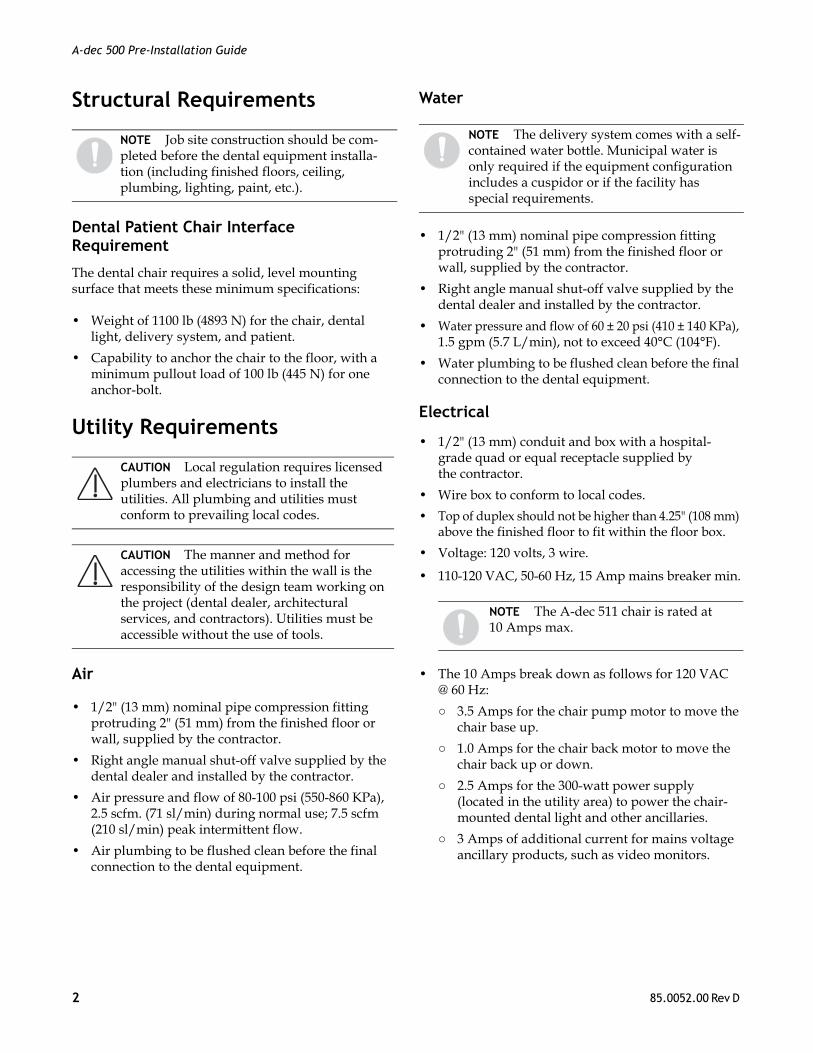
Structural Requirements
Dental Patient Chair Interface Requirement
The dental chair requires a solid, level mounting surface that meets these minimum specifications:
• Weight of 1100 lb (4893 N) for the chair, dental light, delivery system, and patient.
• Capability to anchor the chair to the floor, with a minimum pullout load of 100 lb (445 N) for one anchor-bolt.
Utility Requirements
Air
• 1/2" (13 mm) nominal pipe compression fitting protruding 2" (51 mm) from the finished floor or wall, supplied by the contractor.
• Right angle manual shut-off valve supplied by the dental dealer and installed by the contractor.
• Air pressure and flow of 80-100 psi (550-860 KPa), 2.5 scfm. (71 sl/min) during normal use; 7.5 scfm (210 sl/min) peak intermittent flow.
• Air plumbing to be flushed clean before the final connection to the dental equipment.
Water
• 1/2" (13 mm) nominal pipe compression fitting protruding 2" (51 mm) from the finished floor or wall, supplied by the contractor.
• Right angle manual shut-off valve supplied by the dental dealer and installed by the contractor.
• Water pressure and flow of 60 ± 20 psi (410 ± 140 KPa), 1.5 gpm (5.7 L/min), not to exceed 40°C (104°F).
• Water plumbing to be flushed clean before the final connection to the dental equipment.
Electrical
• 1/2" (13 mm) conduit and box with a hospital-grade quad or equal receptacle supplied by the contractor.
• Wire box to conform to local codes.
• Top of duplex should not be higher than 4.25" (108 mm) above the finished floor to fit within the floor box.
• Voltage: 120 volts, 3 wire.
• 110-120 VAC, 50-60 Hz, 15 Amp mains breaker min.
• The 10 Amps break down as follows for 120 VAC @ 60 Hz:
○ 3.5 Amps for the chair pump motor to move the chair base up.
○ 1.0 Amps for the chair back motor to move the chair back up or down.
○ 2.5 Amps for the 300-watt power supply (located in the utility area) to power the chair-mounted dental light and other ancillaries.
○ 3 Amps of additional current for mains voltage ancillary products, such as video monitors.
NOTE Job site construction should be com-pleted before the dental equipment installa-tion (including finished floors, ceiling, plumbing, lighting, paint, etc.).
CAUTION Local regulation requires licensed plumbers and electricians to install the utilities. All plumbing and utilities must conform to prevailing local codes.
CAUTION The manner and method for accessing the utilities within the wall is the responsibility of the design team working on the project (dental dealer, architectural services, and contractors). Utilities must be accessible without the use of tools.
NOTE The delivery system comes with a self-contained water bottle. Municipal water is only required if the equipment configuration includes a cuspidor or if the facility has special requirements.
NOTE The A-dec 511 chair is rated at 10 Amps max.
2 85.0052.00 Rev D
A-dec 500 Pre-Installation Guide
Central Vacuum
• Plumbing up to the floor box utility center and its termination point is to be specified by the central vacuum supplier (terminates in the utility center).
• Wet systems:
○ Plumbing to terminate with 5/8" (16 mm) O.D. tube protruding 1" perpendicular to the floor.
○ 10 ± 2 in Hg, 9 scfm minimum.
Gravity Drain
• 1-1/2" (38 mm) nominal pipe protruding 1" (25 mm) from finished floor. Trap to be placed in line, conforming to local codes, contractor-supplied.
• Floor mount only. Not recommended for wall mount utilities.
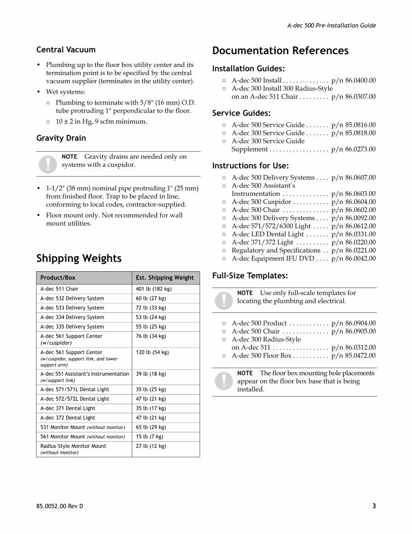
Shipping Weights
Documentation References
Installation Guides: ○ A-dec 500 Install . . . . . . . . . . . . . . p/n 86.0400.00○ A-dec 300 Install 300 Radius-Style
on an A-dec 511 Chair . . . . . . . . . p/n 86.0307.00
Service Guides: ○ A-dec 500 Service Guide . . . . . . . p/n 85.0816.00○ A-dec 300 Service Guide . . . . . . . p/n 85.0818.00○ A-dec 300 Service Guide
Supplement . . . . . . . . . . . . . . . . . . p/n 86.0273.00
Instructions for Use:○ A-dec 500 Delivery Systems . . . . p/n 86.0607.00○ A-dec 500 Assistant’s
Instrumentation . . . . . . . . . . . . . . p/n 86.0603.00○ A-dec 500 Cuspidor . . . . . . . . . . . p/n 86.0604.00○ A-dec 500 Chair . . . . . . . . . . . . . . p/n 86.0602.00○ A-dec 300 Delivery Systems . . . . p/n 86.0092.00○ A-dec 571/572/6300 Light . . . . . p/n 86.0612.00○ A-dec LED Dental Light . . . . . . . p/n 86.0331.00○ A-dec 371/372 Light . . . . . . . . . . p/n 86.0220.00○ Regulatory and Specifications . . p/n 86.0221.00○ A-dec Equipment IFU DVD . . . . p/n 86.0042.00
Full-Size Templates:
○ A-dec 500 Product . . . . . . . . . . . . p/n 86.0904.00○ A-dec 500 Chair . . . . . . . . . . . . . . p/n 86.0905.00○ A-dec 300 Radius-Style
on A-dec 511 . . . . . . . . . . . . . . . . . p/n 86.0312.00○ A-dec 500 Floor Box . . . . . . . . . . . p/n 85.0472.00
NOTE Gravity drains are needed only on systems with a cuspidor.
Product/Box Est. Shipping Weight
A-dec 511 Chair 401 lb (182 kg)
A-dec 532 Delivery System 60 lb (27 kg)
A-dec 533 Delivery System 72 lb (33 kg)
A-dec 334 Delivery System 53 lb (24 kg)
A-dec 335 Delivery System 55 lb (25 kg)
A-dec 561 Support Center (w/cuspidor)
76 lb (34 kg)
A-dec 561 Support Center (w/cuspidor, support link, and lower support arm)
120 lb (54 kg)
A-dec 551 Assistant’s Instrumentation (w/support link)
39 lb (18 kg)
A-dec 571/571L Dental Light 35 lb (25 kg)
A-dec 572/572L Dental Light 47 lb (21 kg)
A-dec 371 Dental Light 35 lb (17 kg)
A-dec 372 Dental Light 47 lb (21 kg)
531 Monitor Mount (without monitor) 65 lb (29 kg)
561 Monitor Mount (without monitor) 15 lb (7 kg)
Radius-Style Monitor Mount (without monitor)
27 lb (12 kg)
NOTE Use only full-scale templates for locating the plumbing and electrical.
NOTE The floor box mounting hole placements appear on the floor box base that is being installed.
85.0052.00 Rev D 3

A-dec 500 Pre-Installation Guide
Views and Dimensions
Utility Placement
Figure 1. Plumbing Elevations (not to scale)
Figure 2. Floor Box Utility Connections
NOTE The dimensional drawings in this section are for reference only. For complete accuracy, use the appropriate full-sized templates.
CAUTION Due to specific plumbing elevation restrictions, the height and placement of utilities in the floor box can affect the ability to use the floor box cover. Failure to provide adequate space will prevent installation and removal of the cover (see Figure 1). Please reference the appropriate full-size template which includes all of the necessary space constraints.
4 85.0052.00 Rev D

A-dec 500 Pre-Installation Guide
A-dec 511 ChairPlan View
27" 686 mm
51.5"1306 mm
10.5" 267 mm
Range of Headrest
Width of Baseplate
Width of Backrest
25"631 mm
63"1600 mm
9" - 18.5"229 - 470 mm
21"533 mm
Forward Chair Travel(from base down
to base up)
SpaceBetween
Arms
85.0052.00 Rev D 5
A-dec 500 Pre-Installation Guide
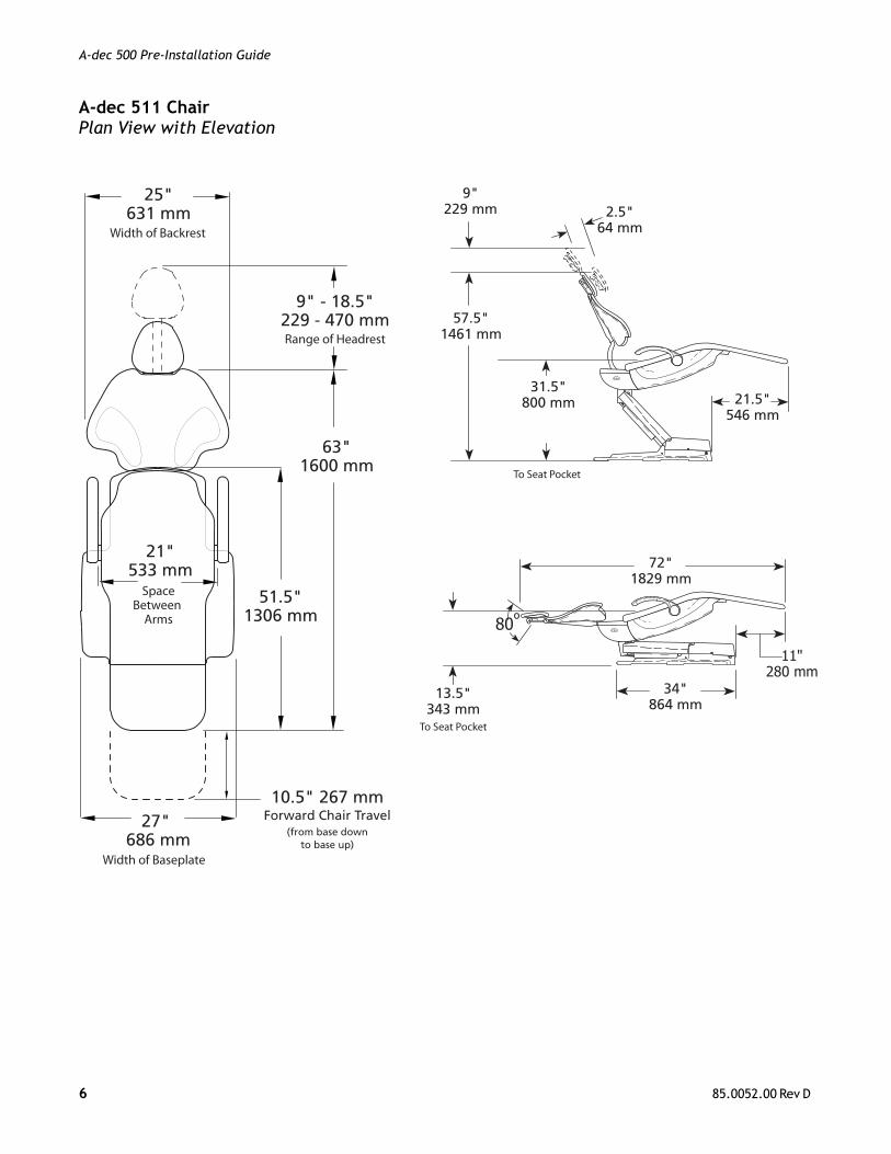
A-dec 511 ChairPlan View with Elevation
27" 686 mm
51.5"1306 mm
10.5" 267 mm
Range of Headrest
Width of Baseplate
Width of Backrest
25"631 mm
63"1600 mm
9" - 18.5"229 - 470 mm
21"533 mm
Forward Chair Travel(from base down
to base up)
SpaceBetween
Arms
To Seat Pocket
To Seat Pocket
13.5"343 mm
72"1829 mm
11"280 mm
34"864 mm
80º
9"229 mm
57.5"1461 mm
2.5"64 mm
21.5"546 mm
31.5"800 mm
6 85.0052.00 Rev D

A-dec 500 Pre-Installation Guide
A-dec 532/533 Delivery SystemPlan View
(shown with 533 system)
18 - 19.5"457 - 495 mm
14.5"368 mm
32 - 34"813 - 864 mm
29" radius737 mm
85.0052.00 Rev D 7

A-dec 500 Pre-Installation Guide
A-dec 532/533 Delivery SystemPlan View with Elevation
(shown with 533 system)
18 - 19.5"457 - 495 mm
14.5"368 mm
32 - 34"813 - 864 mm
29" radius737 mm
9 - 18.5"229 mm - 470 mm
Range of Headrest
71"1795 mm
30.5"775 mmFull Base Up
(forward chair travel = 10.5" [267 mm])
8 85.0052.00 Rev D
A-dec 500 Pre-Installation Guide
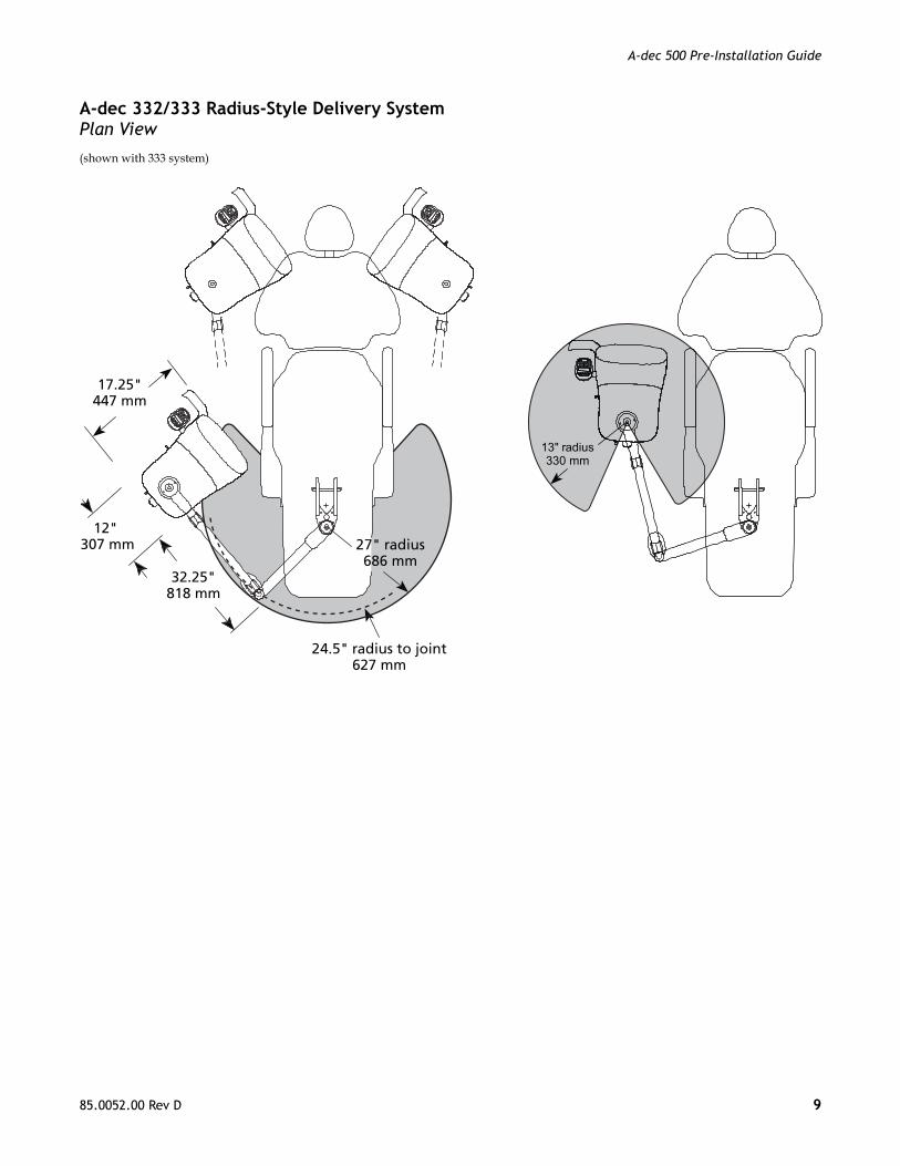
A-dec 332/333 Radius-Style Delivery SystemPlan View
(shown with 333 system)
17.25"447 mm
32.25"818 mm
27" radius686 mm
12" 307 mm
24.5" radius to joint627 mm
13" radius330 mm
85.0052.00 Rev D 9
A-dec 500 Pre-Installation Guide
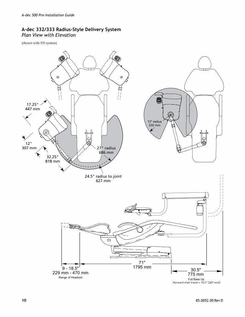
A-dec 332/333 Radius-Style Delivery SystemPlan View with Elevation
(shown with 333 system)
13" radius330 mm
30.5"775 mm
9 - 18.5"229 mm - 470 mm
Range of Headrest
71"1795 mm
Full Base Up (forward chair travel = 10.5" [267 mm])
17.25"447 mm
32.25"818 mm
27" radius686 mm
12" 307 mm
24.5" radius to joint627 mm
10 85.0052.00 Rev D
A-dec 500 Pre-Installation Guide
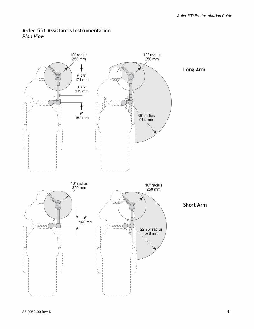
A-dec 551 Assistant’s InstrumentationPlan View
10" radius250 mm
10" radius250 mm
6.75"171 mm
13.5"243 mm
6"152 mm 36" radius
914 mm
10" radius250 mm
10" radius250 mm
22.75" radius578 mm
6"152 mm
Long Arm
Short Arm
85.0052.00 Rev D 11

A-dec 500 Pre-Installation Guide
A-dec 561 Support Center, Cuspidor, and Monitor MountPlan View
14.5"368 mm
15.5" radius394 mm
27"686 mm
23"584 mm
12 85.0052.00 Rev D
A-dec 500 Pre-Installation Guide
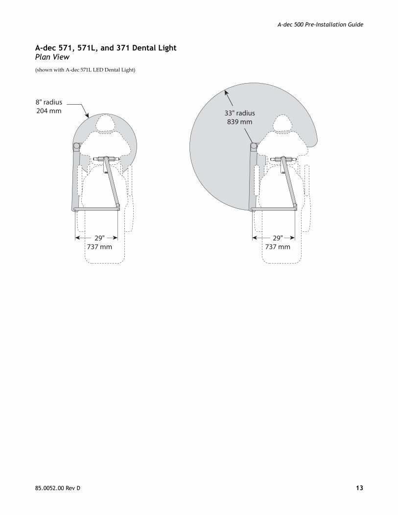
A-dec 571, 571L, and 371 Dental LightPlan View
(shown with A-dec 571L LED Dental Light)
29"737 mm
29"737 mm
8" radius204 mm 33" radius
839 mm
85.0052.00 Rev D 13
A-dec 500 Pre-Installation Guide
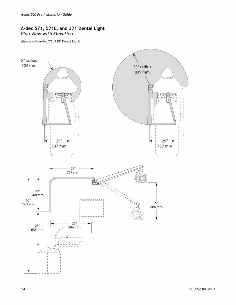
A-dec 571, 571L, and 371 Dental LightPlan View with Elevation
(shown with A-dec 571L LED Dental Light)
29"737 mm
29"737 mm
8" radius204 mm 33" radius
839 mm
25"635 mm
20"508 mm
60"1524 mm
29"737 mm
27"686 mm
23"504 mm
14 85.0052.00 Rev D
A-dec 500 Pre-Installation Guide
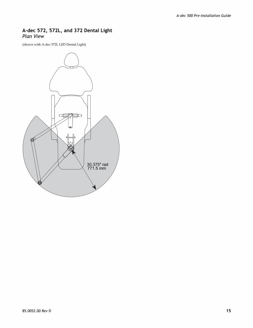
A-dec 572, 572L, and 372 Dental LightPlan View
(shown with A-dec 572L LED Dental Light)
30.375" rad771.5 mm
85.0052.00 Rev D 15

A-dec 500 Pre-Installation Guide
A-dec 572, 572L, and 372 Dental LightPlan View with Elevation
(shown with A-dec 572L LED Dental Light)
30.375" rad771.5 mm
27"686 mm
737 mm29"
63.75"1619 mm
A-dec 572 Light
A-dec 372 Light
A-dec LED Light
16 85.0052.00 Rev D
A-dec 500 Pre-Installation Guide
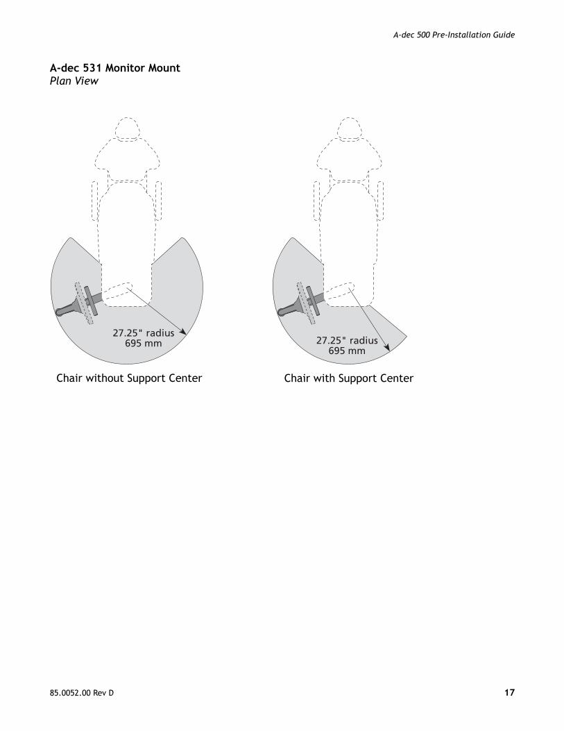
A-dec 531 Monitor MountPlan View
27.25" radius695 mm
27.25" radius695 mm
Chair without Support Center Chair with Support Center
85.0052.00 Rev D 17
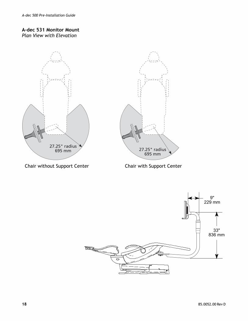
A-dec 500 Pre-Installation Guide
A-dec 531 Monitor MountPlan View with Elevation
27.25" radius695 mm
27.25" radius695 mm
33"836 mm
9"229 mm
Chair without Support Center Chair with Support Center
18 85.0052.00 Rev D
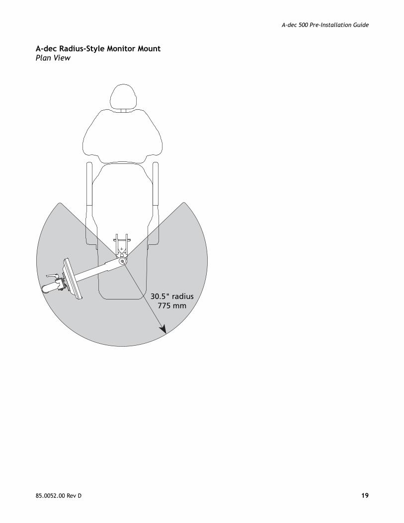
A-dec 500 Pre-Installation Guide
A-dec Radius-Style Monitor MountPlan View
30.5" radius775 mm
85.0052.00 Rev D 19
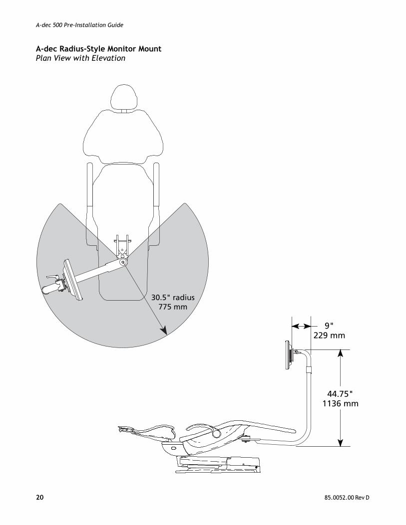
A-dec 500 Pre-Installation Guide
A-dec Radius-Style Monitor MountPlan View with Elevation
44.75"1136 mm
9"229 mm
30.5" radius775 mm
20 85.0052.00 Rev D
A-dec 500 Pre-Installation Guide
85.0052.00 Rev D 21
A-dec 500 Pre-Installation Guide
A-dec Headquarters2601 Crestview DriveNewberg, OR 97132 USATel: 1.800.547.1883 Within USA/CanadaTel: 1.503.538.7478 Outside USA/CanadaFax: 1.503.538.0276www.a-dec.com / www.a-dec.biz
85.0052.00 Rev D Copyright 2012 A-dec Inc.
All rights reserved.
A-dec Inc. makes no warranty of any kindwith regard to the content in this document
including, but not limited to, the impliedwarranties of merchantability and
fitness for a particular purpose.
Regulatory Information
Regulatory information is provided with A-dec equipment as mandated by agency requirements. This information is delivered in the equipment’s Instructions for Use or the separate Regulatory Information and Specifications document. If you need this information, please go to the Document Library at www.a-dec.com.