Embed Size (px)
Citation preview

Owner’s Guide
CASCADE®
1040 Chair
85.2605.00
85260500.QXD 3/13/06 9:53 AM Page i

Cascade Chair Serial Number Location:• On the upper structure, under the upholstery
For service information contact your local authorized A-dec dealer.
Check with local codes and A.D.A. (Americans with Disabilities Act)Requirements for Installation of this product.
NEWBERG, OREGON 97132 USA2601 CRESTVIEW DRIVE
Designated EU Representative: A-dec Dental U.K., Ltd.Austin House, 11 Liberty Way, Attleborough Fields,
Nuneaton, Warwickshire, England CV116RZTele: (44) 24 7635 0901
SN: J828287 REF: 2122
1999
MADE IN USA
SERIALNUMBER
MODELNUMBER
YEAR MANUFACTURED
ALPHABETICAL EQUIVALENTTO THE NUMERAL OF THEMONTH MANUFACTURED
A January
B February
C March
D April
E May
F June
G July
H August
I September
J October
K November
L December
Serial Number Identification
85260500.QXD 3/13/06 9:53 AM Page ii

Printed in U.S.A. • Copyright © 2006 • All Rights Reserved
Warranty
All product names used in this document are trademarks or
registered trademarks of their respective holders.
A-dec warrants all products in this catalog against defectsin material or workmanship for one year from time ofdelivery. A-dec’s sole obligation under the warranty is toprovide parts for the repair, or at its option, to provide thereplacement product (excluding labor). The buyer shallhave no other remedy. All special, incidental, andcoincidental damages are excluded.
Written notice of breach of warranty must be given to A-dec within the warranty period. The warranty does notcover damage resulting from improper installation ormaintenance, accident or misuse. The warranty does notcover damage resulting from the use of cleaning,disinfecting or sterilization chemicals and processes. Thewarranty also does not cover light bulbs. Failure to followinstructions provided in the A-dec owner’s guide(operation and maintenance instructions) may void the warranty.
A-dec warrants A-dec dental chair cylinders, both lift andtilt, for ten years from the date of purchase of the chair orthe cylinder. This warranty is retroactive to A-dec chaircylinders already in the field. The warranty covers chaircylinders A-dec finds to have manufacturing relatedirregularities. Stool cylinders are covered under A-dec‘sone-year warranty.
No other warranties as to merchantability or otherwise are made.
85260500.QXD 3/13/06 9:53 AM Page iii

Cascade 1040 Chair
Cascade 1040 Chair
85260500.QXD 3/13/06 9:53 AM Page iv

1
Cascade 1040 Chair
Serial number location, service information, andwarranty information are located on the insidefront cover and front page.
About Your Cascade Chair ............................. 2Chair LED.......................................................... 2Chair Stop Plate .............................................. 28-Function Footswitch .................................... 3Touch Pad ....................................................... 3Programming the Chair .....................................5Swivel Brake ................................................... 8Double-Articulating Headrest ........................ 9
Headrest Positioning for Wheelchair ..... 10Headrest Drift Adjustment ..................... 11
Upholstery Replacement .............................. 12Back Upholstery ..................................... 12Double-Articulating
Headrest Upholstery ......................... 13Seat Upholstery ...................................... 14Armrest Upholstery ................................ 15
Care Instructions .......................................... 16Adjustments and Specifications ................... 17Maintenance ................................................ 17Safety Considerations for
Accessory Equipment ............................... 18Transporting the Dental Unit ......................... 18Identification of Symbols ............................. 19Classification of Equipment (EN 60601-1) .... 19
CONTENTS
85260500.QXD 3/13/06 9:53 AM Page 1

Your Cascade chair is an electronically controlled,hydraulically powered dental chair (see Figure 1).
Chair functions are controlled by the 8-functionfootswitch or touch pad (see Figure 2 or 2a on page 3).
The chair LED indicates the status of the chair:
ON: Normal operation.
SLOW BLINK: The cuspidor or stop plate limitswitches have been activated. Remove any obstructingobject.
The chair stop plate (see Figure 1) stops the chairimmediately when any part of it is pressed. Shouldanything inadvertently become lodged under the chair,press Base UP on the footswitch or touch pad to raisethe chair so the object can be removed. As long aspressure is applied to the stop plate, the chair base willnot go down any further.
2
Cascade 1040 Chair
Figure 1. Lift, Tilt, and Stop Plate
CHAIRSTOPPLATE
BASE LIFT
CHAIR BACK /TOEBOARD TILT
Chair LED
Chair Stop Plate
About Your Cascade Chair
LED
85260500.QXD 3/13/06 9:53 AM Page 2

The 8-function footswitch (see Figure 2) or the chairtouch pad (see Figure 2a) gives you both manual andprogrammed control of chair positioning. The arrowson the footswitch and touch pad manually control chairback/toeboard tilt and chair lift. The numbered buttonsare for Entry/ Exit and programmed chair positions.
3
Cascade 1040 Chair
8-Function Footswitch
Touch Pad
1 2
30
Figure 2. 8-Function Footswitch
BASE UP
BACK DOWN
BASE DOWN
BACK UP
PROGRAM BUTTON
PROGRAMMABLEPOSITION (1)
PROGRAMMABLEPOSITION (2)
PROGRAMMABLEENTRY/EXIT (0)
CUSPIDOR/RETURN (3)
3
21
0
Figure 2a. Chair Touch Pad
BASE UP
BACK DOWN
BASE DOWN
BACK UP
PROGRAM BUTTON
PROGRAMMABLEPOSITION (1)
PROGRAMMABLEPOSITION (2)
PROGRAMMABLEENTRY/EXIT (0)
CUSPIDOR/RETURN (3)
85260500.QXD 3/13/06 9:53 AM Page 3

Manual Controls
The Base Up/Down (lift) function controls chair lift,or vertical movement. To raise the chair, push the uparrow on the footswitch or touch pad. To lower thechair, push the down button on the footswitch or touchpad. Push the button until the chair reaches the desiredheight, then release it.
The Back Up/Down (tilt) function controls the chairback/toeboard tilt. To raise the chair back, push the rightarrow on the footswitch or touch pad. To lower the chairback, push the left arrow on the footswitch or touchpad. Push the button until the chair back reaches thedesired position, then release it.
Program Button
The Program Button (located on the top middle of thefootswitch, or in between the arrows on the touch pad)is used to save the settings for Entry/ Exit (0),programmable positions (1 and 2), andCuspidor/Return (3).
4
Cascade 1040 Chair
85260500.QXD 3/13/06 9:53 AM Page 4

Programmable Positions 1 and 2
To send the chair to a programmed operating position,push either 1 or 2 (or press 1 or 2 on the touch pad).Positions 1 and 2 are programmed at the factory tomove the chair to the same position.
To change a programmable position, locate theprogram button on the footswitch or touch pad (see Figures 2 or 2a on page 4).
1. Using the manual arrows on the footswitch ortouch pad, set the chair to the operating position thatyou prefer.
2. Press and release the program button. Anaudible tone will be emitted. Then, within fourseconds, push the button for 1or 2 to store thatposition. You will hear an audible tone confirming thatthe programmable function has been reprogrammed.
3. Check the programmed position by manuallymoving the chair to another position. Then push either1 or 2 programmed in Step 2. The chair should moveautomatically to the position set in Step 1.
5
Cascade 1040 Chair
Programming the Chair
NOTEWhen 1 or 2 are pressed on the footswitch ortouch pad, the chair base and back go to thepreset position.
To stop the chair at any point, press any button on the footswitch (or press any button on the touch pad).
85260500.QXD 3/13/06 9:53 AM Page 5

Optional Program Functions
Position 3 is factory set in the Cuspidor/Returnmode. In this mode, the chair back will rise to apre-programmed upright position providing the patientaccess to the cuspidor. Pressing position 3 a second timelowers the chair back to its previous operating position.
Position 3 may also be used as a third Pre-Position oras a last recall.
Contact an authorized A-dec Dealer to have Position 3reconfigured to a third Pre-Position or as a last positionrecall.
6
Cascade 1040 Chair
85260500.QXD 3/13/06 9:53 AM Page 6

Entry/ Exit (0)
To send the chair to a preset entry/exit position, pushthe position 0 button (see Figure 2 or 2a on page 3).
If you want to change the preset entry/exit position,first locate the program button on the footswitch ortouch pad (see Figure 2 or 2a on page 3).
1. Using the manual arrows, set the chair to thedesired patient entry/exit position.
2. Press and release the program button. Anaudible tone will be emitted. Then, within fourseconds, press the Entry/Exit (0) button on thefootswitch or touch pad. You will hear an audible toneconfirming that the chair has been reprogrammed. Thisstores your preferred patient entry/exit position.
3. Check the Entry/ Exit (0) function by manuallymoving the chair to another position. Push the Entry/Exit (0) button. The chair should move automatically tothe position you set in Step 1.
7
Cascade 1040 Chair
NOTEWhen pushed, Entry/ Exit (0) will cause thechair base and back to go to the presetentry/exit position.
To stop the chair at any point, push any button on the footswitch or touch pad.
85260500.QXD 3/13/06 9:53 AM Page 7

When engaged, the chair swivel brake restrictsrotation of the chair. With the brake released, you canrotate the chair to any position within approximately30° either side of center. To unlock the swivel brake,push the brake lever to the right. To lock the swivelbrake, push the brake lever to the left.
If the chair swivels left or right with the brakeengaged, or if it is difficult to move with the brakedisengaged, the swivel brake tension must be adjusted.
Using a 3⁄16-inch hex key, adjust the swivel braketension. Turn the adjusting screw clockwise to increasebrake friction. Turn the screw counterclockwise todecrease brake friction.
8
Cascade 1040 Chair
Swivel Brake
Figure 4. Swivel Brake Adjustment
ADJUSTING SCREW
LOCKED UNLOCKED
85260500.QXD 3/13/06 9:53 AM Page 8

The locking knob allows you to easily adjust theheadrest for a full range of positions.
To position the headrest, release the locking knob byturning the knob out (counterclockwise), then adjustthe headrest as necessary to fit the head and neck. Lockthe headrest in the desired position by turning the knobin (clockwise).
To move the headrest higher or lower, simply pull upor push down on the headrest until it is at the desiredheight.
9
Cascade 1040 Chair
Figure 5. Double-Articulating Headrest
LOCKINGKNOB
Double-Articulating Headrest
85260500.QXD 3/13/06 9:53 AM Page 9

The headrest can be used to accommodate wheelchairpatients. Slide the headrest up until it is free from thechair, turn it 180°, then slide it back into the backrestand push it all the way down. Run the chair to its fullBack Up position. Adjust headrest height by moving thechair up or down (using the Base Up function on thefootswitch or touch pad), then position the headrest asdesired.
10
Cascade 1040 Chair
Figure 6. Headrest Positioning forWheelchair Usage
Headrest Positioning for Wheelchair
85260500.QXD 3/13/06 9:53 AM Page 10

If the headrest drifts downward, or if it is difficult tomove up or down, the glide bar tension must beadjusted. Remove the headrest glide bar to access theadjusting screw.
Using a Phillips screwdriver, adjust the glide bartension. Turn the adjusting screw clockwise three to fourrevolutions to increase friction and hold the headrestmore securely. Turn the screw counterclockwise three tofour revolutions to decrease friction and allow theheadrest to move up and down more freely. Reinstallthe headrest and recheck glide bar tension.
11
Cascade 1040 Chair
Figure 7. Headrest Drift Adjustment
HEADRESTGLIDE BAR
Headrest Drift Adjustment
85260500.QXD 3/13/06 9:53 AM Page 11

A-dec’s unique formed upholstery makes replacingupholstery quick and easy.
The upholstery on your Cascade 1040 Chair isinstalled in four sections: back, headrest, seat, andarmrests. Each section is easily removed and replaced.
To remove back upholstery firmly grasp the bottomedge of the cushion and lift upward, approximately 1-inch, to release the four large, flat-headed fastenersfrom the cushion key-slots.
To install back upholstery place the large fastenerheads in the cushion keyhole pockets then push in anddown in one motion.
12
Cascade 1040 Chair
Figure 8. Replacing the Back Upholstery
KEY SLOT IN BACK UPHOLSTERY
LARGE HEADFASTENER
Upholstery Replacement
Back Upholstery
85260500.QXD 3/13/06 9:53 AM Page 12

Use the following procedure to replace the headrestupholstery.
1. Loosen the headrest knob and rotate the headrestto a full upright position.
2. Remove the top Phillips mounting screw from theheadrest back-plate, located just above the knobassembly.
3. Rotate the headrest back 45° to expose the twoPhillips mounting screws on the lower headrestback-plate (see Figure 9). Remove the two screwsand the headrest cushion.
4. To attach the replacement upholstery, reverse thisprocedure.
13
Cascade 1040 Chair
Figure 9. Replacing the Headrest Upholstery
HEADRESTBACK-PLATE
MOUNTINGSCREWS(one hidden)
TOPMOUNTINGSCREW(hidden)
Double-Articulating Headrest Upholstery
85260500.QXD 3/13/06 9:53 AM Page 13
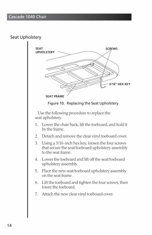
Use the following procedure to replace the seat upholstery.
1. Lower the chair back, lift the toeboard, and hold itby the frame.
2. Detach and remove the clear vinyl toeboard cover.
3. Using a 3/16-inch hex key, loosen the four screwsthat secure the seat/toeboard upholstery assemblyto the seat frame.
4. Lower the toeboard and lift off the seat/toeboardupholstery assembly.
5. Place the new seat/toeboard upholstery assemblyon the seat frame.
6. Lift the toeboard and tighten the four screws, thenlower the toeboard.
7. Attach the new clear vinyl toeboard cover.
14
Cascade 1040 Chair
Figure 10. Replacing the Seat Upholstery
SEAT FRAME
SCREWS
3/16" HEX KEY
SEAT UPHOLSTERY
Seat Upholstery
85260500.QXD 3/13/06 9:53 AM Page 14

Use the following procedure to replace the armrestupholstery assembly.
1. Lift the armrest away from the seat pocket. Use aPhillips screwdriver and remove the retaining screwfrom the underside of the armrest.
2. Push the armrest upholstery assembly toward thetoe end of the chair, approximately 1⁄2-inch, thenlift the armrest upholstery away from the arm.
3. Place the new armrest on the arm and slide ittoward the chair back. Replace the retaining screwon underside.
15
Cascade 1040 Chair
Figure 11. Replacing the Armrest Upholstery
RETAININGSCREW
ARMRESTUPHOLSTERYASSEMBLY
Armrest Upholstery
85260500.QXD 3/13/06 9:53 AM Page 15

For recommended asepsis instructions, refer to the Asepsis section of the Owner’s Guide(A-dec Publication No. 85.0696.00).
16
Cascade 1040 Chair
Care Instructions
85260500.QXD 3/13/06 9:53 AM Page 16
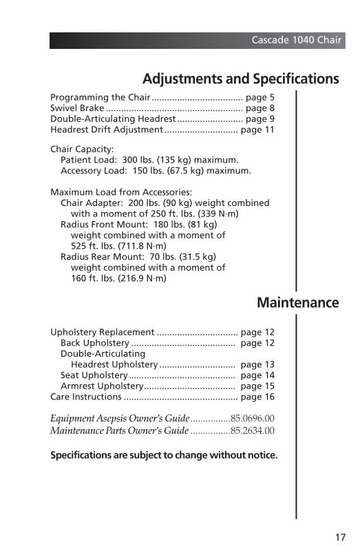
Programming the Chair .................................... page 5Swivel Brake ...................................................... page 8Double-Articulating Headrest .......................... page 9Headrest Drift Adjustment ............................. page 11
Chair Capacity:Patient Load: 300 lbs. (135 kg) maximum.Accessory Load: 150 lbs. (67.5 kg) maximum.
Maximum Load from Accessories:Chair Adapter: 200 lbs. (90 kg) weight combined
with a moment of 250 ft. lbs. (339 N·m)Radius Front Mount: 180 lbs. (81 kg)
weight combined with a moment of 525 ft. lbs. (711.8 N·m)
Radius Rear Mount: 70 lbs. (31.5 kg) weight combined with a moment of 160 ft. lbs. (216.9 N·m)
Upholstery Replacement ................................ page 12Back Upholstery ......................................... page 12Double-Articulating
Headrest Upholstery .............................. page 13Seat Upholstery.......................................... page 14Armrest Upholstery.................................... page 15
Care Instructions ............................................. page 16
Equipment Asepsis Owner’s Guide................85.0696.00Maintenance Parts Owner’s Guide ................85.2634.00
Specifications are subject to change without notice.
17
Cascade 1040 Chair
Adjustments and Specifications
Maintenance
85260500.QXD 3/13/06 9:53 AM Page 17
The use of accessory equipment not complying withthe equivalent safety requirements of this equipmentmay lead to a reduced level of safety of the resultingsystem.
Consideration relating to the use of accessoryequipment shall include:
Evidence that Safety Certification of the accessoryequipment has been performed in accordance to theappropriate IEC 601 and IEC 601-1 HarmonizedNational Standards.
When transporting the dental unit the chair baseshould be fully down, and the chair back should be fullyup. The chair body should be secured to the chairbaseplate. Do not lift the chair by the chair body.
The delivery system should be over the seat upholstery and the light should be centered above the chair.
The delivery system and light should be secured toprevent movement. The entire Dental Unit should besecured to the transporting vehicle.
18
Cascade 1040 Chair
Safety Considerations forAccessory Equipment
Transporting the Dental Unit
85260500.QXD 3/13/06 9:53 AM Page 18

19
Cascade 1040 Chair
Identification of Symbols
Symbol Description
Recognized by Underwriters Laboratories Inc. with respect to electricshock, fire and mechanical hazards only in accordance with UL 60601-1(2601-1) and under mutual recognition agreement with CAN/CSAC22.2, No. 601.1.
Classified by Underwriters Laboratories Inc. with respect to electricshock, fire and mechanical hazards only in accordance with UL 60601-1(2601-1) and under mutual recognition agreement with CAN/CSAC22.2, No. 601.1.
UL listed to UL 61010A-1, BS EN 61010-2-010 and Canadian (CAN/CSAC22.2, No. 1010.1-92) safety standards.
Conforms to European Directives (refer to Declaration of Conformity)
Protective earth (ground).
Functional earth (ground).
Attention, consult accompanying documents. No user serviceable parts.Attention, line voltage. Only licensed electrician should remove cover.
Type B Applied Part.
Class II equipment.
Caution: Metal surfaces can be hot during and following the dry cycle.
85260500.QXD 3/13/06 9:53 AM Page 19

20
Cascade 1040 Chair
Classification of Equipment (EN-60601-1)
Type/Mode Classification
Type of shockprotection
CLASS I EQUIPMENT: Dental chairs, dental lights, and power supplies
CLASS II EQUIPMENT: Chair, wall, and cart mounted delivery systems
Degree of shockprotection
TYPE B APPLIED PART: Delivery systems only
Degree ofprotectionagainst wateringress
ORDINARY EQUIPMENT: All products
Mode ofoperation
CONTINUOUS OPERATION: All models except Dental ChairsCONTINUOUS OPERATION WITH INTERMITTENT LOADING:Dental chairs -
5% duty cycle
FlammableGasses
Not suitable for use in the presence of a flammable anestheticmixture with air, oxygen, or nitrous oxide, where such gasses mayaccumulate in concentration (closed space).
85260500.QXD 3/13/06 9:53 AM Page 20

Electrical Rating
Type Specification
Volts 100/110-120/220-240 VAC
Frequency 50-60 Hz
Current As configured and specified in equipment manual (productslabeled 15A or greater require dedicated circuit, identified indistribution panel)
Environmental Specifications
Temperature/Humidity
Specification
Storage/Transportation
Temperature: -40°C to 70°C (-40°F to 158°F)Relative Humidity: 95% maximum
Operating Temperature: 10°C to 40°C (50°F to 104°F)Relative Humidity: 95% maximum
Indoor Use Altitude up to 2,000m (6, 563 ft.), installation category II, pollu-tion degree 2. (UL 61010A-1 and CAN/CSA C22.2, No. 1010.1-92only)
Cascade 1040 Chair
85260500.QXD 3/13/06 9:53 AM Page 21

85.2605.002006-03 Rev H(05188)
Printed in USA.©A-dec Inc. 2006
All Rights Reserved
USA and Canada2601 Crestview Drive
Newberg, Oregon 97132 USAPhone: 1.800.547.1883
1.503.538.7478Fax: 1.503.538.0276
www.a-dec.com
InternationalPhone: 1.503.538.9471
Fax: 1.503.538.5911
Distribution CentersA-dec Australia
41-43 Bowden StreetAlexandria, NSW 2015, Australia
Phone: 61 (0)2 9699 4600www.adec.com.au
A-dec United KingdomAustin House
11 Liberty WayNuneaton, Warwickshire
England CV11 6RZ Phone: 0800 ADECUK (233285) Within UK
44 24 7635 0901 Outside UKwww.a-dec.co.uk
85260500.QXD 3/13/06 9:53 AM Page 22
![Final project Math 1040 - Maria Davilamariadavila.weebly.com/.../math1040final_project_recovered.pdf · Final project Math 1040 [FINAL PROJECT MATH 1040] April 30, 2014 2 ... Conclusion](https://img.pdfslide.us/doc/110x75/5aa1ba647f8b9a80378c059e/final-project-math-1040-maria-project-math-1040-final-project-math-1040-april.jpg)