Embed Size (px)
Citation preview

PUB. NO. 85-0808-00R
SERVICE GUIDEFOR
A-DEC DENTAL CHAIRS
MODELS
1010/15/20
October 1993

Table of Contents
Section 1 - IntroductionOverview ................................................................................................................................. 1-1Year and Model Variations ....................................................................................................... 1-2
Section 2 - Service InformationIntroduction .............................................................................................................................. 2-1Systems Description ............................................................................................................... 2-2
Hydraulics ........................................................................................................................ 2-2Electronic Control ............................................................................................................ 2-2
Functional Description ............................................................................................................ 2-5Power Supply ................................................................................................................... 2-5Footswitches .................................................................................................................... 2-5Back and Base Positioning Potentiometers .................................................................... 2-5Safety Stop Switches ....................................................................................................... 2-6Back Up and Base Up Limit Switches ............................................................................. 2-6Hydraulic System ............................................................................................................. 2-7
Electrical Schematics .............................................................................................................. 2-8Hydraulic Schematic ............................................................................................................. 2-14Service and Support ............................................................................................................. 2-15
Section 3 - TroubleshootingIntroduction .............................................................................................................................. 3-1Contents .................................................................................................................................. 3-1Navigating the Flow Charts ..................................................................................................... 3-2
Section 4 - Illustrated Parts BreakdownService Parts Codes ............................................................................................................... 4-1
Appendix A - Specifications ................................................................................................. A-1
Appendix B - Service Notes ................................................................................................. B-1
Index ................................................................................................................................................... I-1
i
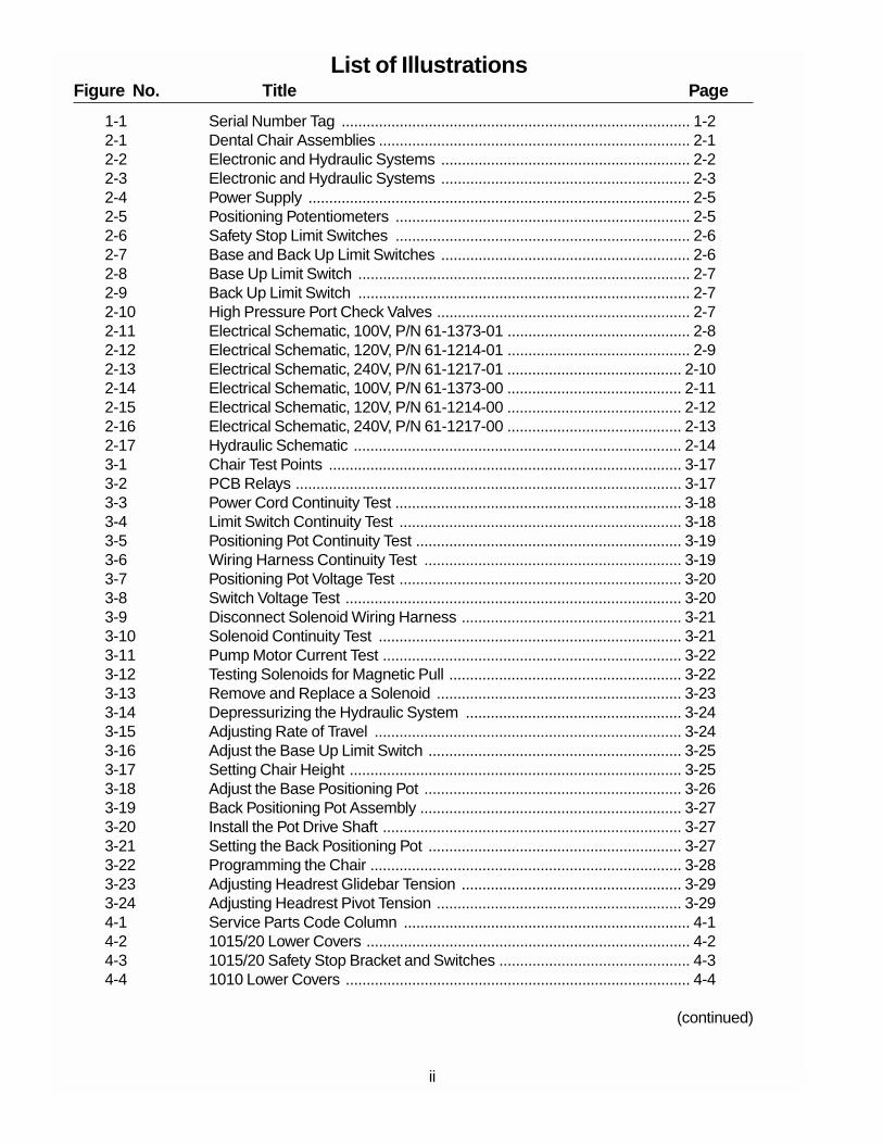
List of IllustrationsFigure No. Title Page
1-1 Serial Number Tag .................................................................................... 1-22-1 Dental Chair Assemblies ........................................................................... 2-12-2 Electronic and Hydraulic Systems ............................................................ 2-22-3 Electronic and Hydraulic Systems ............................................................ 2-32-4 Power Supply ............................................................................................ 2-52-5 Positioning Potentiometers ....................................................................... 2-52-6 Safety Stop Limit Switches ....................................................................... 2-62-7 Base and Back Up Limit Switches ............................................................ 2-62-8 Base Up Limit Switch ................................................................................ 2-72-9 Back Up Limit Switch ................................................................................ 2-72-10 High Pressure Port Check Valves ............................................................. 2-72-11 Electrical Schematic, 100V, P/N 61-1373-01 ............................................ 2-82-12 Electrical Schematic, 120V, P/N 61-1214-01 ............................................ 2-92-13 Electrical Schematic, 240V, P/N 61-1217-01 .......................................... 2-102-14 Electrical Schematic, 100V, P/N 61-1373-00 .......................................... 2-112-15 Electrical Schematic, 120V, P/N 61-1214-00 .......................................... 2-122-16 Electrical Schematic, 240V, P/N 61-1217-00 .......................................... 2-132-17 Hydraulic Schematic ............................................................................... 2-143-1 Chair Test Points ..................................................................................... 3-173-2 PCB Relays ............................................................................................. 3-173-3 Power Cord Continuity Test ..................................................................... 3-183-4 Limit Switch Continuity Test .................................................................... 3-183-5 Positioning Pot Continuity Test ................................................................ 3-193-6 Wiring Harness Continuity Test .............................................................. 3-193-7 Positioning Pot Voltage Test .................................................................... 3-203-8 Switch Voltage Test ................................................................................. 3-203-9 Disconnect Solenoid Wiring Harness ..................................................... 3-213-10 Solenoid Continuity Test ......................................................................... 3-213-11 Pump Motor Current Test ........................................................................ 3-223-12 Testing Solenoids for Magnetic Pull ........................................................ 3-223-13 Remove and Replace a Solenoid ........................................................... 3-233-14 Depressurizing the Hydraulic System .................................................... 3-243-15 Adjusting Rate of Travel .......................................................................... 3-243-16 Adjust the Base Up Limit Switch ............................................................. 3-253-17 Setting Chair Height ................................................................................ 3-253-18 Adjust the Base Positioning Pot .............................................................. 3-263-19 Back Positioning Pot Assembly ............................................................... 3-273-20 Install the Pot Drive Shaft ........................................................................ 3-273-21 Setting the Back Positioning Pot ............................................................. 3-273-22 Programming the Chair ........................................................................... 3-283-23 Adjusting Headrest Glidebar Tension ..................................................... 3-293-24 Adjusting Headrest Pivot Tension ........................................................... 3-294-1 Service Parts Code Column ..................................................................... 4-14-2 1015/20 Lower Covers .............................................................................. 4-24-3 1015/20 Safety Stop Bracket and Switches .............................................. 4-34-4 1010 Lower Covers ................................................................................... 4-4
(continued)
ii

List of Illustrations(continued)
Figure No. Title Page
4-5 Base Positioning Potentiometer, Limit Switch and Bracket Assembly ...... 4-54-6 1010/15/20 Hydraulic Power Assembly .................................................... 4-64-7 Hydraulic Manifold/Solenoid Assembly .................................................... 4-84-8 Base Lift and Back Tilt Hydraulic Cylinders ............................................ 4-104-9 Back Cover and Armrests ....................................................................... 4-114-10 Upper Structure ....................................................................................... 4-124-11 Back Positioning Potentiometer, Limit Switch and Bracket Assembly .... 4-134-12 Headrest Glidebar Brake Assemblies ..................................................... 4-144-13 Vac Back Manifold and Pivot Arm Leveling Assembly ............................ 4-154-14 Vac Back Cover and Pivot Arm Assembly .............................................. 4-164-15 Swivel Brake Assembly ........................................................................... 4-184-16 Toeboard and Seat Assembly ................................................................. 4-204-17 Standard Articulating Headrests ............................................................. 4-214-18 Double Articulating Headrest .................................................................. 4-224-19 Multi-Function Foot Switch ..................................................................... 4-244-20 8-Function Footswitch ............................................................................. 4-26A-1 1010/15/20 Chair Footprint Dimensions .................................................. A-1A-2 1010 Chair Vertical Dimensions ............................................................... A-1A-3 1015/20 Chair Vertical Dimensions .......................................................... A-2
iii

SECTION 1INTRODUCTION
This manual contains service related information forA-dec Model 1010, 1015 and 1020 dental chairs.Before using this manual, you should become familiarwith its contents, especially Section 3: Trouble-shooting. Being familiar with the content of the manualwill reduce your time in the doctor's office, your time inresearch, and the frustration of trying to find informa-tion.
Overview
This manual is divided into the following four sections:
Section 1 - Introduction
Describes manual contents and how to determinewhat information in this manual is applicable to thedental chair you are working on.
Section 2 - Service Information
Section 2 provides a functional description of how thechair works. This section also contains chair electricaland hydraulic systems diagrams and schematics.
Section 3 - Troubleshooting
When there is something wrong, don't panic. Just usethe troubleshooting procedures in Section 3. Section3 describes the symptoms of various problems, theneither tells you how to fix the problem or directs you toan appropriate procedure.
Section 4 - Illustrated Parts Breakdown
Section 4 contains the exploded parts drawings forModels 1010/15/20 Dental Chair major assembliesand includes parts lists. The parts lists specify A-decpart number, description and service parts codes.Use the information in Section 4 when orderingreplacement parts.
1-1

Year and Model Variations
When necessary we will distinguish between varia-tions of a chair model by serial number or by themonth and year manufactured. The month and yearmanufactured information is included in the serialnumber of each A-dec Dental Chair. The month ofmanufacture is indicated by a code character (seeTable 1-1). The year is indicated by the digit followingthe month code (see Figure 1-1).
The serial number tag can be found in one of twoplaces: 1) on the top surface of a chair's upper struc-ture (raise the toeboard for access). 2) on the under-side of the right-hand armrest support.
1-2
Table 1-1 Month of Manufacture Codes
CODE MONTH OF MANUFACTURE
A JanuaryB FebruaryC MarchD AprilE MayF JuneG JulyH AugustI SeptemberJ OctoberK NovemberL December
R NEWBERG OR, USA
SERIAL NUMBER: E902440
MODEL NUMBER 1015
INDICATES THE MONTHOF MANUFACTURE
THE SECOND DIGIT OF THE YEAR MANUFACTURED
CHAIR MODELNUMBER
CHAIR SERIAL NUMBER
Figure 1-1 Serial Number Tag

SECTION 2
SERVICE INFORMATION
Introduction
A-dec Model 1010, 1015 and 1020 chairs are elec-tronically controlled, hydraulically powered dentalchairs. Switches on the Multi-Function Footswitch areused to position the chair and program Auto-Position-ing functions into the chair. The hydraulic system iscontrolled by the electronic control module usingrelays and solenoid-actuated valves. The parts of the1010/15/20 chairs are shown in Figure 2-1.
2-1
WARNING
THE CHAIR CONTROLLER AND SOLENOIDSUSE PRIMARY INPUT AC VOLTAGES (100, 120,OR 240V AC) FOR OPERATION. TO AVOID PER-SONAL INJURY, FOLLOW ALL SAFETY PRE-CAUTIONS WHEN WORKING ON THE CHAIR.
Figure 2-1. Dental Chair Assemblies
BASEPLATE TOEBOARD
UPPER STRUCTUREAND SWIVEL(UNDER TOEBOARD)
CHAIR BACK
ARMRESTS
HEAD REST
LIFTARM
290077

Systems Description
Refer to Figure 2-2 below and Figure 2-3 on page 2-3while reading the following descriptions.
Hydraulics
The hydraulic system consists of:
An hydraulic fluid reservoir. The fluid level in thereservoir can be seen through the sides of thereservoir and is serviced via a top fill cap.
Hydraulic cylinders for base lift and back tilt func-tions. Pressurized hydraulic fluid extends thecylinder rod during base and back up functions.Springs and gravity retract the rod during baseand back down functions.
A motor-driven hydraulic pump (and startercapacitor) that supplies hydraulic fluid from thereservoir, under pressure, to the chair lift and tilthydraulic cylinders for Back Up and Base Upfunctions.
A solenoid/manifold assembly to gate hydraulicfluid to and from the two cylinders. Depending onthe chair function called for, the controller selectswhich solenoid-actuated manifold valves areopened or closed. The solenoid/manifold assem-bly also includes four adjustable needle valvesused to restrict or divert the flow of hydraulic fluidto and from the lift and tilt cylinders. These valvesprovide the rate of travel adjustment for chairbase and back movement.
Electronic ControlThe electronic control system consists of:
A microcomputer-based controller that: A) scansthe footswitch for a closed switch, B) senses thecurrent position of the chair, C) senses the statusof the chair limit switches, D) stores programmedauto-positioning data, and E) controls the electro-hydraulic system.
A programming button that, when pressed, causesthe controller to save the current chair position val-ues for Pre-Position or Auto-Return functions.
A multi-function footswitch used to position thechair. When programming the chair, the footswitchis used to indicate which function (Pre-Position orAuto-Return) is being programmed.
Chair base and back limit switches to detect whenthe maximum allowed up travel is reached. Thecontroller will stop chair base or back up move-ment if the limit switch is actuated.
On chair Models 1015 and 1020 only, two safetystop switches to stop chair movement if any objectis caught between the underside of the lift arm andthe baseplate (see Figure 2-1 on page 2-1). Allchair functions with the exception of Base Up aredisabled when a safety stop limit switch is actuated.
One safety stop switch to stop chair movement ifany object is caught under a chair-mounted cuspi-dor (not shown). All chair functions with the excep-tion of Base Up are disabled when a safety stoplimit switch is actuated.
Two potentiometers that provide the controller withcurrent position values for the chair base andback. The controller saves position values whenbeing programmed and compares that value withcurrent position value for Pre-Position or Auto-Return functions.
Five electro-magnetic relays used by the controllerto turn the hydraulic pump on or off and to selectsolenoid actuated manifold valves to open orclose.
A set of test points which allow you to position thechair without using the multi-function footswitch.Refer to Section 3, Troubleshooting, page 3-17for more information.
2-2
Figure 2-2. Electronic and Hydraulic Systems
290098
1
2
3
4
5
6
7
8
9
A
AD
B
B
C
B
C
D
3
5
4
4
7
7
2 9 1 8

2-3
Figure 2-3. Electronic and Hydraulic Systems
P2
SW
1
TE
ST
PO
INT
S
F2 3/10 ASLO BLOW
F1 1/8 ASLO BLOW
BK UP BK DN BS UP
EXDN
ENT
P1
FU
SE
FU
SE
TILTCYLINDER
LIFTCYLINDER
HYDRAULICFLUIDRESERVOIR
SOLENOID/MANIFOLDASSEMBLY
CYLINDERSCAVENGELINES
PUMP SUPPLY LINEFOR UP FUNCTIONS,CYLINDER RETURNLINE FOR DOWNFUNCTIONS
CYLINDER RETURNLINE FOR DOWNFUNCTIONS
CYLINDER SUPPLY LINEFOR UPFUNCTIONS
CYLINDER SUPPLY LINESFOR UP FUNCTIONS,CYLINDER RETURNLINES FOR DOWNFUNCTIONS
MOTOR/PUMP
MOTOR/PUMPCAPACITOR
MICROCOMPUTER-BASEDCONTROLLER
MULTI-FUNCTIONFOOTSWITCH
BACK POSITIONINGPOTENTIOMETER
BASE POSITIONINGPOTENTIOMETER
SAFETY STOPLIMIT SWITCHES(1015/20 ONLY)
BACK UP LIMITSWITCH
BASE UP LIMITSWITCH
MOTOR/PUMPRELAY
BACK UPRELAY
BACK DNRELAY
BASE UPRELAY
BASE DNRELAY
P5
P4
P6
PROGRAMMINGBUTTON
3
7
7
2
5
4
4
8
8
8
9 1
B
B
D
A
C
P14
CUSPIDOR SAFETYSWITCH
6
IMPORTANT
Due to changes to the 1010/15/20 printed circuitboard (PCB), there are new part numbers for thePCB, PCB cover, and the PCB store (program-ming) button extension assembly. A new PCB hasone or two fuse holders mounted vertically on theboard, the older PCB has a single fuse holdermounted flat on the board. Newer parts are notinterchangeable with the older parts. The PCBpart number is located in the lower left corner of thecircuit board. Refer to Appendix B - ServiceNotes, page B-2 for additional information.
080098
Functional Description
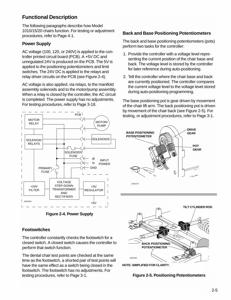
The following paragraphs describe how Model1010/15/20 chairs function. For testing or adjustmentprocedures, refer to Page 4-1.
Power Supply
AC voltage (100, 120, or 240V) is applied to the con-troller printed circuit board (PCB). A +5V DC andunregulated 24V is produced on the PCB. The 5V isapplied to the positioning potentiometers and limitswitches. The 24V DC is applied to the relays andrelay driver circuits on the PCB (see Figure 2-4).
AC voltage is also applied, via relays, to the manifoldassembly solenoids and to the motor/pump assembly.When a relay is closed by the controller, the AC circuitis completed. The power supply has no adjustments.For testing procedures, refer to Page 3-18.
Footswitches
The controller constantly checks the footswitch for aclosed switch. A closed switch causes the controller toperform that switch function.
The dental chair test points are checked at the sametime as the footswitch, a shorted pair of test points willhave the same effect as a switch being closed in thefootswitch. The footswitch has no adjustments. Fortesting procedures, refer to Page 3-1.
Back and Base Positioning Potentiometers
The back and base positioning potentiometers (pots)perform two tasks for the controller:
1. Provide the controller with a voltage level repre-senting the current position of the chair base andback. The voltage level is stored by the controllerfor later reference during auto-positioning.
2. Tell the controller where the chair base and backare currently positioned. The controller comparesthe current voltage level to the voltage level storedduring auto-positioning programming.
The base positioning pot is gear driven by movementof the chair lift arm. The back positioning pot is drivenby movement of the chair back (see Figure 2-5). Fortesting, or adjustment procedures, refer to Page 3-1.
2-5
N
+5VREGULATOR
+5V
+24VFILTER
SOLENOIDSFUSE
PRIMARYFUSE
MOTORRELAY
INPUTPOWER
GND
Ø
SOLENOIDRELAYS
SOLENOIDS
MOTOR/PUMP
VOLTAGESTEP-DOWN
TRANSFORMERAND
RECTIFIERS
PCB
Figure 2-4. Power Supply
Figure 2-5. Positioning Potentiometers
BASE POSITIONINGPOTENTIOMETER
DRIVEGEAR
POTGEAR
BACK POSITIONINGPOTENTIOMETER
NOTE: SIMPLIFIED FOR CLARITY.
TILT CYLINDER ROD
080099
290079
290066
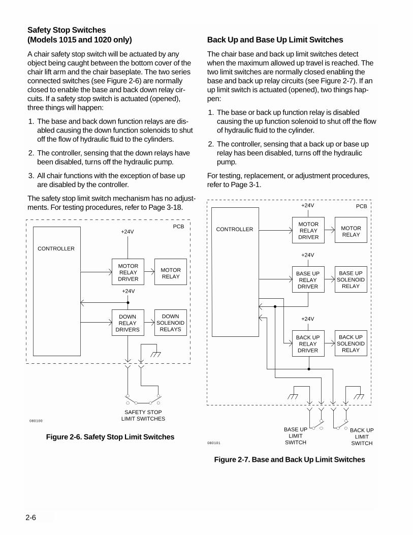
Safety Stop Switches(Models 1015 and 1020 only)
A chair safety stop switch will be actuated by anyobject being caught between the bottom cover of thechair lift arm and the chair baseplate. The two seriesconnected switches (see Figure 2-6) are normallyclosed to enable the base and back down relay cir-cuits. If a safety stop switch is actuated (opened),three things will happen:
1. The base and back down function relays are dis-abled causing the down function solenoids to shutoff the flow of hydraulic fluid to the cylinders.
2. The controller, sensing that the down relays havebeen disabled, turns off the hydraulic pump.
3. All chair functions with the exception of base upare disabled by the controller.
The safety stop limit switch mechanism has no adjust-ments. For testing procedures, refer to Page 3-18.
Back Up and Base Up Limit Switches
The chair base and back up limit switches detectwhen the maximum allowed up travel is reached. Thetwo limit switches are normally closed enabling thebase and back up relay circuits (see Figure 2-7). If anup limit switch is actuated (opened), two things hap-pen:
1. The base or back up function relay is disabledcausing the up function solenoid to shut off the flowof hydraulic fluid to the cylinder.
2. The controller, sensing that a back up or base uprelay has been disabled, turns off the hydraulicpump.
For testing, replacement, or adjustment procedures,refer to Page 3-1.
2-6
+24V
SAFETY STOPLIMIT SWITCHES
DOWNRELAY
DRIVERS
CONTROLLER
PCB
DOWNSOLENOID
RELAYS
MOTORRELAY
MOTORRELAYDRIVER
+24V
Figure 2-6. Safety Stop Limit SwitchesBASE UP
LIMITSWITCH
BACK UPLIMIT
SWITCH
CONTROLLER
PCB
BASE UPRELAYDRIVER
BASE UPSOLENOID
RELAY
MOTORRELAY
MOTORRELAYDRIVER
+24V
BACK UPRELAYDRIVER
BACK UPSOLENOID
RELAY
+24V
+24V
Figure 2-7. Base and Back Up Limit Switches
080100
080101

The base up limit switch is actuated by a pin locatedon the positioning potentiometer drive gear (see Fig-ure 2-8). The back up limit switch is actuated by aglide block which is part of the back tilt mechanism(see Figure 2-9).
Hydraulic System
For up functions, hydraulic fluid is drawn from thereservoir by the motor/pump and delivered, underpressure, to the manifold/solenoid assembly. In themanifold assembly, fluid travels past an openedsolenoid operated valve and out to the cylinder,extending the cylinder rod. For down functions, asolenoid operated valve is opened, allowing fluid fromthe cylinders to flow back through the manifoldassembly and to the reservoir.
The motor/pump unit consists of a hydraulic pumpand electric motor. The pump is driven by the electricmotor. Internal thermal overload protection is includedin the electric motor.
Once the chair lift and tilt cylinders have been pres-surized, hydraulic pressure must be maintained in thecylinders to hold the chair in position. To prevent fluiddraining back to the reservoir and allowing the chair tosettle or drift, each of the high pressure output ports tothe cylinders includes a check valve (see Figure 2-10). The high pressure output ports are in thehydraulic blocks.
2-7
Figure 2-8. Base Up Limit Switch
Figure 2-9. Back Up Limit Switch
ACTUATOR
LIMIT SWITCH
ACTUATORLIMIT SWITCH
WARNING
Do not service any hydraulic connections untilyou have depressurized the hydraulic system(see page 3-24). Do not attempt to remove acylinder until you have read the instructionsincluded with each new cylinder. You may beseriously injured if you fail to follow all safety pre-cautions and instructions.
Figure 2-10. High Pressure Port Check Valves
O-RING
CHECK VALVE
BASE LIFT HYDRAULIC BLOCK
BACK TILTHYDRAULICBLOCK
STEM SPRING
HIGH PRESSUREFITTING
290098
290099
290100
D111N4148
+12V
+5V
Q82N3904
MURATAPKB30SPC-3001R5
12K
Q72N3904
R451K
BS UP SOL100V
BS DN SOL100V
BK UP SOL100V
BK DN SOL100V
MOTOR100V YEL
C150
WHT
RED
F2 3/10 A
DUPLEXRECEPTACLE(OPTIONAL)
+5V
C52200
D51N4001
1
6
234
587
F11/8A
U57805
AC
AC
+
-
+24V
C4470
C6.011KV
DB1
+5V
RN21K
1
2
3
4
R312K
D41N4148
D31N4148
D21N4148
D11N4148
K2BK DN
K3BK UP
K4BS DN
K5BS UP
K1MOTOR
+24V
Q1
Q2
Q3
Q42N6427(5 PLACES)
BACKPOSITION
POTENTIOMETER
BASEPOSITION
POTENTIOMETER
+5V
RN410K
1
5234
U1
+5V
D7 MBD701
D6MBD701
D8MBD701
21
22
23
24
25
26
27
28
29
30
31
32
33
34
35
36+5V
2
4
3
1
U3NMC9306N
DO
DI
SK
CS
8
5
37
38
39
40
+5V
C11.0
C233
+5V
+5V
R212K
1
2
3
4
5
6
7
8
C30.01
1
3
2
+5V
9
10
11
12
13
9
7
5
3
6
4
2
8
14
15
16
17
18
19
20
5 4 3 2
1
RN11K
+5V
+5V
R25K
R15K
TE
ST
PO
INT
S
BK UP
BK DN
BS UP
BS DN
ENTRY/EXIT
PRE-POSITION
GND
COL 4
+5V
BS UP COM
BS DN COM
ENTRY/EXIT
PRE-POS
COL 1
COL 2
COL 3
BS DN
BS UP
BK DN
BK UP
U4SN74LS244N
12
18
16
14
17
15
13
11
19
10
1
STORE
SW1
U6MC34064
RN31K
1
2 3 4 5
FOOTSWITCH
20
P9
P10
P11
P12
J10
J9
J11
J12
P5
J5
P4
J4
J13 J14
J2 P2
P1
1
2
3
4
5
6
7
8
9
10
11
12
13
14
1
2
3
4
5
6
7
8
9
10
1
2
3
2
4
1
5
3
1
1
3
2
2
1 2 3
1 2 3 41 2 3
1 2 3
AU
XIL
IAR
Y C
ON
TR
OL
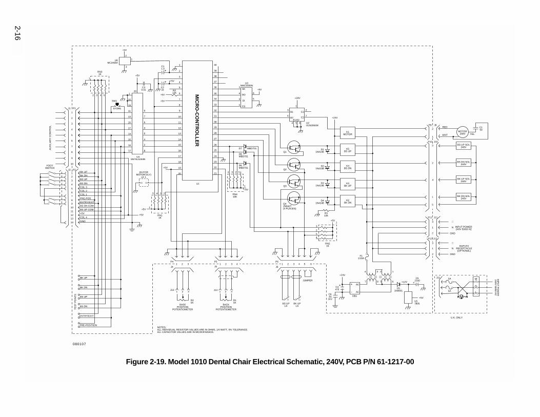
NOTES:ALL INDIVIDUAL RESISTOR VALUES ARE IN OHMS, 1/4 WATT, 5% TOLERANCE.ALL CAPACITOR VALUES ARE IN MICROFARADS.
+12V
∅
N
GND
+5V
J1
INP
UT
PO
WE
R100V
50/60 HZ
LMP1
F3 10 A SW 2
2
1
3
+C1233
12 P13AIR/ELECTRIC SWITCHHANDPIECE LOCKOUT
Q5D9
1N4148
+
+
++
MIC
RO
-CO
NT
RO
LL
ER
BS UPLS
BK UPLS
P6
J61 2 3 4 5 6
S2"3" FUNCTION
SETS
P14
J141 2
CUSPIDORLS
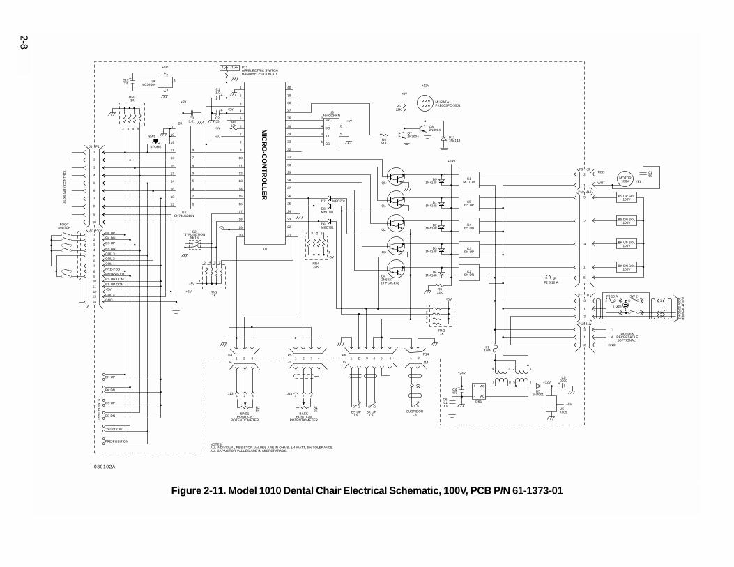
Figure 2-11. Model 1010 Dental Chair Electrical Schematic, 100V, PCB P/N 61-1373-01
2-8
080102A
2-9
D111N4148
+12V
+5V
Q82N3904
MURATAPKB30SPC-3001R5
12K
Q72N3904
R451K
BS UP SOL120V
BS DN SOL120V
BK UP SOL120V
BK DN SOL120V
MOTOR120V YEL
C150
WHT
RED
INPUT POWER120V 50/60 HZ
DUPLEXRECEPTACLE(OPTIONAL)
+5V
C52200
D51N4001
1
6
234
587
F11/8A
U57805
AC
AC
+
-
+24V
C4470
C6.011KV
DB1
+5V
RN21K
1
2
3
4
R312K
D41N4148
D31N4148
D21N4148
D11N4148
K2BK DN
K3BK UP
K4BS DN
K5BS UP
K1MOTOR
+24V
Q1
Q2
Q3
Q42N6427(5 PLACES)
BACKPOSITION
POTENTIOMETER
BASEPOSITION
POTENTIOMETER
+5V
RN410K
1
5234
U1
+5V
D7 MBD701
D6MBD701
D8MBD701
21
22
23
24
25
26
27
28
29
30
31
32
33
34
35
36+5V
2
4
3
1
U3NMC9306N
DO
DI
SK
CS
8
5
37
38
39
40
+5V
C11.0
C233
+5V
+5V
R212K
1
2
3
4
5
6
7
8
C30.01
1
3
2
+5V
9
10
11
12
13
9
7
5
3
6
4
2
8
14
15
16
17
18
19
20
5 4 3 2
1
RN11K
+5V
+5V
R25K
R15K
TE
ST
PO
INT
S
BK UP
BK DN
BS UP
BS DN
ENTRY/EXIT
PRE-POSITION
GND
COL 4
+5V
BS UP COM
BS DN COM
ENTRY/EXIT
PRE-POS
COL 1
COL 2
COL 3
BS DN
BS UP
BK DN
BK UP
U4SN74LS244N
12
18
16
14
17
15
13
11
19
10
1
STORE
SW1
U6MC34064
RN31K
1
2 3 4 5
FOOTSWITCH
20
P9
P10
P11
P12
J10
J9
J11
J12
P5
J5
P4
J4
J13 J14
J2 P2
P1
1
2
3
4
5
6
7
8
9
10
11
12
13
14
1
2
3
4
5
6
7
8
9
10
1
2
3
2
4
1
5
3
1
1
3
2
2
1 2 3
1 2 3 41 2 3
1 2 3
AU
XIL
IAR
Y C
ON
TR
OL
NOTES:ALL INDIVIDUAL RESISTOR VALUES ARE IN OHMS, 1/4 WATT, 5% TOLERANCE.ALL CAPACITOR VALUES ARE IN MICROFARADS.
+12V
∅
∅
N
N
GND
GND
+5V
J1
+C1233
+
+
+
+
D91N4148Q5
MIC
RO
-CO
NT
RO
LL
ER
F2 3/10 A
BS UPLS
BK UPLS
P6
J61 2 3 4 5 6
SAFETY PLATELIMIT SWITCHES
(1015/20)
JUMPER(1010)
P14
J141 2
CUSPIDORLS
S2"3" FUNCTION
SETS
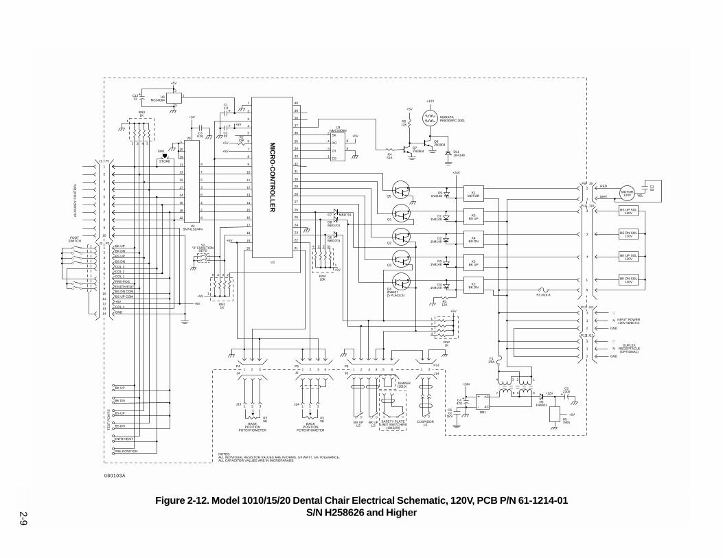
Figure 2-12. Model 1010/15/20 Dental Chair Electrical Schematic, 120V, PCB P/N 61-1214-01S/N H258626 and Higher
080103A

2-10
D111N4148
+12V
+5V
Q82N3904
MURATAPKB30SPC-3001R5
12K
Q72N3904
R451K
BS UP SOL240V
BS DN SOL240V
BK UP SOL240V
BK DN SOL240V
MOTOR240V YEL
C150
WHT
RED
INPUT POWER240V 50/60 HZ
DUPLEXRECEPTACLE(OPTIONAL)
+5V
C52200
D51N4001
1
6
234
587
F115/100A
U57805
AC
AC
+
-
+24V
C4470
C6.011KV
DB1
+5V
RN21K
1
2
3
4
R312K
D41N4148
D31N4148
D21N4148
D11N4148
K2BK DN
K3BK UP
K4BS DN
K5BS UP
K1MOTOR
+24V
Q1
Q2
Q3
Q42N6427(5 PLACES)
BACKPOSITION
POTENTIOMETER
BASEPOSITION
POTENTIOMETER
+5V
RN410K
1
5234
U1
+5V
D7 MBD701
D6MBD701
D8MBD701
21
22
23
24
25
26
27
28
29
30
31
32
33
34
35
36+5V
2
4
3
1
U3NMC9306N
DO
DI
SK
CS
8
5
37
38
39
40
+5V
C11.0
C233
+5V
+5V
R212K
1
2
3
4
5
6
7
8
C30.01
1
3
2
+5V
9
10
11
12
13
9
7
5
3
6
4
2
8
14
15
16
17
18
19
20
5 4 3 2
1
RN11K
+5V
+5V
R25K
R15K
TE
ST
PO
INT
S
BK UP
BK DN
BS UP
BS DN
ENTRY/EXIT
PRE-POSITION
GND
COL 4
+5V
BS UP COM
BS DN COM
ENTRY/EXIT
PRE-POS
COL 1
COL 2
COL 3
BS DN
BS UP
BK DN
BK UP
U4SN74LS244N
12
18
16
14
17
15
13
11
19
10
1
STORE
SW1
U6MC34064
RN31K
1
2 3 4 5
FOOTSWITCH
20
P9
P10
P11
P12
J10
J9
J11
J12
P5
J5
P4
J4
J13 J14
J2 P2
P1
1
2
3
4
5
6
7
8
9
10
11
12
13
14
1
2
3
4
5
6
7
8
9
10
1
2
3
2
4
1
5
3
1
1
3
2
2
1 2 3
1 2 3 41 2 3
1 2 3
AU
XIL
IAR
Y C
ON
TR
OL
NOTES:ALL INDIVIDUAL RESISTOR VALUES ARE IN OHMS, 1/4 WATT, 5% TOLERANCE.ALL CAPACITOR VALUES ARE IN MICROFARADS.
+12V
∅
∅
N
N
GND
GND
+5V
J1
+C1233
+
+
+
+
D91N4148Q5
MIC
RO
-CO
NT
RO
LL
ER
J11
U.K. ONLY
INP
UT
PO
WE
R240V
50/60 HZL
N
5A
5A
BS UPLS
BK UPLS
P6
J61 2 3 4 5 6
SAFETY PLATELIMIT SWITCHES
(1020)
JUMPER(1010)
P14
J141 2
CUSPIDORLS
S2"3" FUNCTION
SETS
Figure 2-13. Model 1010/20 Dental Chair Electrical Schematic, 240V, PCB P/N 61-1217-01S/N H258114 and Higher
080104A

2-11
BS UP SOL100V
BS DN SOL100V
BK UP SOL100V
BK DN SOL100V
MOTOR100V YEL
C150
WHT
RED
F2 3/10 A
DUPLEXRECEPTACLE(OPTIONAL)
+5V
C52200
D51N4001
1
6
234
587
F11/8A
U57805
AC
AC
+
-
+24V
C4470
C6.011KV
DB1
+5V
RN21K
1
2
3
4
R312K
D41N4148
D31N4148
D21N4148
D11N4148
K2BK DN
K3BK UP
K4BS DN
K5BS UP
K1MOTOR
+24V
Q1
Q2
Q3
Q42N6427(5 PLACES)
BS UPLS
BK UPLSBACK
POSITIONPOTENTIOMETER
BASEPOSITION
POTENTIOMETER
+5V
RN410K
1
5234
U1
+5V
D7 MBD701
D6MBD701
D8MBD701
21
22
23
24
25
26
27
28
29
30
31
32
33
34
35
36+5V
2
4
3
1
U3NMC9306N
DO
DI
SK
CS
8
5
37
38
39
40
+5V
C11.0
C233
+5V
+5V
R212K
1
2
3
4
5
6
7
8
C30.01
1
3
2
+5V
9
10
11
12
13
9
7
5
3
6
4
2
8
14
15
16
17
18
19
20(IN FORMOTOR DLY)
LK 1
5 4 3 2
1
RN11K
+5V
+5V
R25K
R15K
TE
ST
PO
INT
S
BK UP
BK DN
BS UP
BS DN
ENTRY/EXIT
PRE-POSITION
GND
COL 4
+5V
BS UP COM
BS DN COM
ENTRY/EXIT
PRE-POS
COL 1
COL 2
COL 3
BS DN
BS UP
BK DN
BK UP
U4SN74LS244N
12
18
16
14
17
15
13
11
19
10
1
STORE
SW1
U6MC34064
RN31K
1
2 3 4 5
FOOTSWITCH
20
P9
P10
P11
P12
J10
J9
J11
J12
P6
J6
P5
J5
P4
J4
J13 J14
J2 P2
P1
1
2
3
4
5
6
7
8
9
10
11
12
13
14
1
2
3
4
5
6
7
8
9
10
1
2
3
2
4
1
5
3
1
1
3
2
2
1 2 3
1 2 3 4 1 2 3 4 5 61 2 3
1 2 3
AU
XIL
IAR
Y C
ON
TR
OL
NOTES:ALL INDIVIDUAL RESISTOR VALUES ARE IN OHMS, 1/4 WATT, 5% TOLERANCE.ALL CAPACITOR VALUES ARE IN MICROFARADS.
+12V
∅
N
GND
+5V
J1
INP
UT
PO
WE
R100V
50/60 HZ
LMP1
F3 10 A SW 2
2
1
3
+C1233
12 P13AIR/ELECTRIC SWITCHHANDPIECE LOCKOUT
Q5D9
1N4148
+
+
++
MIC
RO
-CO
NT
RO
LL
ER
CUSPIDORLS
Figure 2-14. Model 1010 Dental Chair Electrical Schematic, 100V, PCB P/N 61-1373-01
080102

2-12
BS UP SOL120V
BS DN SOL120V
BK UP SOL120V
BK DN SOL120V
MOTOR120V YEL
C150
WHT
RED
INPUT POWER120V 50/60 HZ
DUPLEXRECEPTACLE(OPTIONAL)
+5V
C52200
D51N4001
1
6
234
587
F11/8A
U57805
AC
AC
+
-
+24V
C4470
C6.011KV
DB1
+5V
RN21K
1
2
3
4
R312K
D41N4148
D31N4148
D21N4148
D11N4148
K2BK DN
K3BK UP
K4BS DN
K5BS UP
K1MOTOR
+24V
Q1
Q2
Q3
Q42N6427(5 PLACES)
BS UPLS
BK UPLSBACK
POSITIONPOTENTIOMETER
BASEPOSITION
POTENTIOMETER
+5V
RN410K
1
5234
U1
+5V
D7 MBD701
D6MBD701
D8MBD701
21
22
23
24
25
26
27
28
29
30
31
32
33
34
35
36+5V
2
4
3
1
U3NMC9306N
DO
DI
SK
CS
8
5
37
38
39
40
+5V
C11.0
C233
+5V
+5V
R212K
1
2
3
4
5
6
7
8
C30.01
1
3
2
+5V
9
10
11
12
13
9
7
5
3
6
4
2
8
14
15
16
17
18
19
20(IN FORMOTOR DLY)
LK 1
5 4 3 2
1
RN11K
+5V
+5V
R25K
R15K
TE
ST
PO
INT
S
BK UP
BK DN
BS UP
BS DN
ENTRY/EXIT
PRE-POSITION
GND
COL 4
+5V
BS UP COM
BS DN COM
ENTRY/EXIT
PRE-POS
COL 1
COL 2
COL 3
BS DN
BS UP
BK DN
BK UP
U4SN74LS244N
12
18
16
14
17
15
13
11
19
10
1
STORE
SW1
U6MC34064
RN31K
1
2 3 4 5
FOOTSWITCH
20
P9
P10
P11
P12
J10
J9
J11
J12
P6
J6
P5
J5
P4
J4
J13 J14
J2 P2
P1
1
2
3
4
5
6
7
8
9
10
11
12
13
14
1
2
3
4
5
6
7
8
9
10
1
2
3
2
4
1
5
3
1
1
3
2
2
1 2 3
1 2 3 4 1 2 3 4 5 61 2 3
1 2 3
AU
XIL
IAR
Y C
ON
TR
OL
SAFETY PLATELIMIT SWITCHES
(1015/20)
JUMPER(1010)
NOTES:ALL INDIVIDUAL RESISTOR VALUES ARE IN OHMS, 1/4 WATT, 5% TOLERANCE.ALL CAPACITOR VALUES ARE IN MICROFARADS.
+12V
∅
∅
N
N
GND
GND
+5V
J1
+C1233
+
+
+
+
D91N4148Q5
MIC
RO
-CO
NT
RO
LL
ER
F2 3/10 A
Figure 2-15. Model 1010/15/20 Dental Chair Electrical Schematic, 120V, PCB P/N 61-1214-01
080103

2-13
BS UP SOL240V
BS DN SOL240V
BK UP SOL240V
BK DN SOL240V
MOTOR240V YEL
C150
WHT
RED
INPUT POWER240V 50/60 HZ
DUPLEXRECEPTACLE(OPTIONAL)
+5V
C52200
D51N4001
1
6
234
587
F115/100A
U57805
AC
AC
+
-
+24V
C4470
C6.011KV
DB1
+5V
RN21K
1
2
3
4
R312K
D41N4148
D31N4148
D21N4148
D11N4148
K2BK DN
K3BK UP
K4BS DN
K5BS UP
K1MOTOR
+24V
Q1
Q2
Q3
Q42N6427(5 PLACES)
BS UPLS
BK UPLSBACK
POSITIONPOTENTIOMETER
BASEPOSITION
POTENTIOMETER
+5V
RN410K
1
5234
U1
+5V
D7 MBD701
D6MBD701
D8MBD701
21
22
23
24
25
26
27
28
29
30
31
32
33
34
35
36+5V
2
4
3
1
U3NMC9306N
DO
DI
SK
CS
8
5
37
38
39
40
+5V
C11.0
C233
+5V
+5V
R212K
1
2
3
4
5
6
7
8
C30.01
1
3
2
+5V
9
10
11
12
13
9
7
5
3
6
4
2
8
14
15
16
17
18
19
20(IN FORMOTOR DLY)
LK 1
5 4 3 2
1
RN11K
+5V
+5V
R25K
R15K
TE
ST
PO
INT
S
BK UP
BK DN
BS UP
BS DN
ENTRY/EXIT
PRE-POSITION
GND
COL 4
+5V
BS UP COM
BS DN COM
ENTRY/EXIT
PRE-POS
COL 1
COL 2
COL 3
BS DN
BS UP
BK DN
BK UP
U4SN74LS244N
12
18
16
14
17
15
13
11
19
10
1
STORE
SW1
U6MC34064
RN31K
1
2 3 4 5
FOOTSWITCH
20
P9
P10
P11
P12
J10
J9
J11
J12
P6
J6
P5
J5
P4
J4
J13 J14
J2 P2
P1
1
2
3
4
5
6
7
8
9
10
11
12
13
14
1
2
3
4
5
6
7
8
9
10
1
2
3
2
4
1
5
3
1
1
3
2
2
1 2 3
1 2 3 4 1 2 3 4 5 61 2 3
1 2 3
AU
XIL
IAR
Y C
ON
TR
OL
NOTES:ALL INDIVIDUAL RESISTOR VALUES ARE IN OHMS, 1/4 WATT, 5% TOLERANCE.ALL CAPACITOR VALUES ARE IN MICROFARADS.
+12V
∅
∅
N
N
GND
GND
+5V
J1
+C1233
+
+
+
+
D91N4148Q5
MIC
RO
-CO
NT
RO
LL
ER
J11
U.K. ONLY
INP
UT
PO
WE
R240V
50/60 HZL
N
5A
5A
SAFETY PLATELIMIT SWITCHES
(1020)
JUMPER(1010)
Figure 2-16. Model 1010/20 Dental Chair Electrical Schematic, 240V, PCB P/N 61-1217-01
080104

2-14
CUSPIDORLS
BS UP SOL100V
BS DN SOL100V
BK UP SOL100V
BK DN SOL100V
MOTOR100V YEL
C150
WHT
RED
F2 3/10 A
DUPLEXRECEPTACLE(OPTIONAL)
+5V
C52200
D51N4001
1
6
234
587
F11/8A
U57805
AC
AC
+
-
+24V
C4470
C6.011KV
DB1
+5V
RN21K
1
2
3
4
R312K
D41N4148
D31N4148
D21N4148
D11N4148
K2BK DN
K3BK UP
K4BS DN
K5BS UP
K1MOTOR
+24V
+24V
1
7
23
6
4 5 8 U2ULN2061M
B1
B2
C1
C2E1 E2
Q1
Q2
Q3
Q42N6427(4 PLACES)
BS UPLS
BK UPLSBACK
POSITIONPOTENTIOMETER
BASEPOSITION
POTENTIOMETER
+5V
RN410K
1
5234
+5V
D7 MBD701
D6MBD701
D8MBD701
21
22
23
24
25
26
27
28
29
30
31
32
33
34
35
36+5V
2
4
3
1
U3NMC9306N
DO
DI
SK
CS
8
5
37
38
39
40
+5V
C11.0
C233
+5V
+5V
R212K
1
2
3
4
5
6
7
8
C30.01
1
3
2
+5V
9
10
11
12
13
9
7
5
3
6
4
2
8
14
15
16
17
18
19
20(IN FORMOTOR DLY)
LK 1
5 4 3 2
1
RN11K
+5V
+5V
R25K
R15K
TE
ST
PO
INT
S
BK UP
BK DN
BS UP
BS DN
ENTRY/EXIT
PRE-POSITION
GND
COL 4
+5V
BS UP COM
BS DN COM
ENTRY/EXIT
PRE-POS
COL 1
COL 2
COL 3
BS DN
BS UP
BK DN
BK UP
U4SN74LS244N
12
18
16
14
17
15
13
11
19
10
1
STORE
SW1
U6MC34064
RN31K
1
2 3 4 5
FOOTSWITCH
20
P9
P10
P11
P12
J10
J9
J11
J12
P6
J6
P5
J5
P4
J4
J13 J14
J2 P2
P1
1
2
3
4
5
6
7
8
9
10
11
12
13
14
1
2
3
4
5
6
7
8
9
10
1
2
3
2
4
1
5
3
1
1
3
2
2
1 2 3
1 2 3 4 1 2 3 4 5 61 2 3
1 2 3
AU
XIL
IAR
Y C
ON
TR
OL
NOTES:ALL INDIVIDUAL RESISTOR VALUES ARE IN OHMS, 1/4 WATT, 5% TOLERANCE.ALL CAPACITOR VALUES ARE IN MICROFARADS.
+12V
∅
N
GND
+5V
J1
+C1233
+
+
+
+
MIC
RO
–CO
NT
RO
LL
ER
12 P13AIR/ELECTRIC SWITCHHANDPIECE LOCKOUTR1
47
INP
UT
PO
WE
R100V
50/60 HZ
LMP1
F3 10 A SW 2
2
1
3
Figure 2-17. Model 1010 Dental Chair Electrical Schematic, 100V, PCB P/N 61-1373-00
080105

2-15
BS UP SOL120V
BS DN SOL120V
BK UP SOL120V
BK DN SOL120V
MOTOR120V YEL
C150
WHT
RED
F2 3/10 A
INPUT POWER120V 50/60 HZ
DUPLEXRECEPTACLE(OPTIONAL)
+5V
C52200
D51N4001
1
6
234
587
F11/8A
U57805
AC
AC
+
-
+24V
C4470
C6.011KV
DB1
+5V
RN21K
1
2
3
4
R312K
D41N4148
D31N4148
D21N4148
D11N4148
K2BK DN
K3BK UP
K4BS DN
K5BS UP
K1MOTOR
+24V
+24V
1
7
23
6
4 5 8 U2ULN2061M
B1
B2
C1
C2E1 E2
Q1
Q2
Q3
Q42N6427(4 PLACES)
BS UPLS
BK UPLS
SAFETY PLATELIMIT SWITCHES
(1015)BACK
POSITIONPOTENTIOMETER
BASEPOSITION
POTENTIOMETER
+5V
RN410K
1
5234
U1
+5V
D7 MBD701
D6MBD701
D8MBD701
21
22
23
24
25
26
27
28
29
30
31
32
33
34
35
36+5V
2
4
3
1
U3NMC9306N
DO
DI
SK
CS
8
5
37
38
39
40
+5V
C11.0
C233
+5V
+5V
R212K
1
2
3
4
5
6
7
8
C30.01
1
3
2
+5V
9
10
11
12
13
9
7
5
3
6
4
2
8
14
15
16
17
18
19
20(IN FORMOTOR DLY)
LK 1
5 4 3 2
1
RN11K
+5V
+5V
R25K
R15K
TE
ST
PO
INT
S
BK UP
BK DN
BS UP
BS DN
ENTRY/EXIT
PRE-POSITION
GND
COL 4
+5V
BS UP COM
BS DN COM
ENTRY/EXIT
PRE-POS
COL 1
COL 2
COL 3
BS DN
BS UP
BK DN
BK UP
U4SN74LS244N
12
18
16
14
17
15
13
11
19
10
1
STORE
SW1
U6MC34064
RN31K
1
2 3 4 5
FOOTSWITCH
20
P9
P10
P11
P12
J10
J9
J11
J12
P6
J6
P5
J5
P4
J4
J13 J14
J2 P2
P1
1
2
3
4
5
6
7
8
9
10
11
12
13
14
1
2
3
4
5
6
7
8
9
10
1
2
3
2
4
1
5
3
1
1
3
2
2
1 2 3
1 2 3 4 1 2 3 4 5 61 2 3
1 2 3
AU
XIL
IAR
Y C
ON
TR
OL
JUMPER(1010)
NOTES:ALL INDIVIDUAL RESISTOR VALUES ARE IN OHMS, 1/4 WATT, 5% TOLERANCE.ALL CAPACITOR VALUES ARE IN MICROFARADS.
+12V
∅
∅
N
N
GND
GND
+5V
J1
+
+
+
+
MIC
RO
-CO
NT
RO
LL
ER
Figure 2-18. Model 1010/15 Dental Chair Electrical Schematic, 120V, PCB P/N 61-1214-00
080106
2-16
BS UP SOL240V
BS DN SOL240V
BK UP SOL240V
BK DN SOL240V
MOTOR240V YEL
C150
WHT
RED
INPUT POWER240V 50/60 HZ
DUPLEXRECEPTACLE(OPTIONAL)
+5V
C52200
D51N4001
1
6
234
587
F11/10A
U57805
AC
AC
+
-
+24V
C4470
C6.011KV
DB1
+5V
RN21K
3
2
5
4
1
R312K
D41N4148
D31N4148
D21N4148
D11N4148
K2BK DN
K3BK UP
K4BS DN
K5BS UP
K1MOTOR
+24V
+24V
1
7
23
6
4 5 8 U2ULN2061M
B1
B2
C1
C2E1 E2
Q1
Q2
Q3
Q42N6427(4 PLACES)
BS UPLS
BK UPLSBACK
POSITIONPOTENTIOMETER
BASEPOSITION
POTENTIOMETER
+5V
RN410K
1
5234
U1
+5V
D7 MBD701
D6MBD701
D8MBD701
21
22
23
24
25
26
27
28
29
30
31
32
33
34
35
36+5V
2
4
3
1
U3NMC9306N
DO
DI
SK
CS
8
5
37
38
39
40
+5V
C11.0
C233
+5V
+5V
R212K
1
2
3
4
5
6
7
8
C30.01
1
3
2
+5V
9
10
11
12
13
9
7
5
3
6
4
2
8
14
15
16
17
18
19
20(IN FORMOTOR DLY)
LK 1
5 4 3 2
1
RN11K
+5V
+5V
R25K
R15K
TE
ST
PO
INT
S
BK UP
BK DN
BS UP
BS DN
ENTRY/EXIT
PRE-POSITION
GND
COL 4
+5V
BS UP COM
BS DN COM
ENTRY/EXIT
PRE-POS
COL 1
COL 2
COL 3
BS DN
BS UP
BK DN
BK UP
U4SN74LS244N
12
18
16
14
17
15
13
11
19
10
1
STORE
SW1
U6MC34064
RN31K
1
2 3 4 5
FOOTSWITCH
20
P9
P10
P11
P12
J10
J9
J11
J12
P6
J6
P5
J5
P4
J4
J13 J14
J2 P2
P1
1
2
3
4
5
6
7
8
9
10
11
12
13
14
1
2
3
4
5
6
7
8
9
10
1
2
3
2
4
1
5
3
1
1
3
2
2
1 2 3
1 2 3 4 1 2 3 4 5 61 2 3
1 2 3
AU
XIL
IAR
Y C
ON
TR
OL
JUMPER
NOTES:ALL INDIVIDUAL RESISTOR VALUES ARE IN OHMS, 1/4 WATT, 5% TOLERANCE.ALL CAPACITOR VALUES ARE IN MICROFARADS.
+12V
∅
∅
N
N
GND
GND
+5V
J1
+
+
+
+
MIC
RO
-CO
NT
RO
LL
ER
J11
U.K. ONLY
INP
UT
PO
WE
R240V
50/60 HZL
N
5A
5A
Figure 2-19. Model 1010 Dental Chair Electrical Schematic, 240V, PCB P/N 61-1217-00
080107

2-17
LIFT CYLINDERSINGLE ACTING - GRAVITY RETURN
BACK TILT CYLINDERSINGLE ACTING - GRAVITY &SPRING RETURNSOLENOID/MANIFOLD ASSEMBLY
HYDPUMP
HYDRAULICFLUID
RESERVOIR
LIFT CYLINDER SCAVENGE LINE
TILT CYLINDER SCAVENGE LINE
BACK DOWNSOLENOID
BACK UPSOLENOID
BASEDOWN
SOLENOID
BASE UPSOLENOID
RATE OFTRAVELADJUSTMENTS
CHECKVALVE
CHECKVALVE
FILTERSCREENS
Figure 2-20. Model 1010/15/20 Dental Chair Hydraulic Schematic
Hydraulic S
chematic
080108

2-18
Service and Support
Given proper care, A-dec Models 1010, 1015 and1020 Dental Chairs will provide years of trouble-freeservice. In the event something does go wrong withthe chair and you are unable to identify and correctthe problem, you should call your authorized A-decdealer or dental equipment supplier. Anytime you callyour dealer or supplier, be prepared to provide the fol-lowing information about the chair.
1. Model number*
2. Serial number*
3. Symptoms of the problem
4. What action you have taken toward correcting theproblem.
* For more information about the chair serial numbertag and where the tag can be found on the chair,refer to Section 1, Introduction, page 1-2.

SECTION 3TROUBLESHOOTING
Introduction
The information in this section will help you find andrepair chair failures. If you are unable to repair thechair, call your authorized A-dec dealer. When callingyour dealer, refer to Section 2, Service Information,page 2-15 before calling.
3-1
ContentsPage
Troubleshooting Flow Charts
Chair is Inoperative ................................................................................................................ 3-3Base or Back Up Function is Inoperative .............................................................................. 3-5Base or Back Down Function is Inoperative ......................................................................... 3-8Unable to Program Auto-Positioning ..................................................................................... 3-9Incomplete Auto-Positioning Cycle ..................................................................................... 3-11Auto-Positioning Function Inoperative ................................................................................ 3-14Back Moves for Base Only Function ................................................................................... 3-15Base Moves for Back Only Function ................................................................................... 3-15
Test, Remove/Replace, and Adjust Procedures
A Using the Chair Test Points ........................................................................................... 3-17B Relay Click Test ............................................................................................................. 3-17C Continuity and Voltage Tests ......................................................................................... 3-18D Pump Motor Test ........................................................................................................... 3-22E Testing Solenoids for Magnetic Pull .............................................................................. 3-22F Remove and Replace a Solenoid .................................................................................. 3-23G Depressurize the Hydraulic System .............................................................................. 3-24H Adjust Base and Back Rate of Travel ............................................................................ 3-24I Adjust a Base Up Limit Switch ....................................................................................... 3-25J Adjust the Base Positioning Pot ..................................................................................... 3-26K Adjust the Back Positioning Pot ..................................................................................... 3-27L Adjust Auto Positioning
Multifunction Footswitch ................................................................................................ 3-288 Function Footswitch .................................................................................................... 3-28
M Adjust Headrest Glidebar Tension ................................................................................. 3-29N Adjust Double Articulating Headrest Pivot Tension ....................................................... 3-30
Navigating the Flow Charts
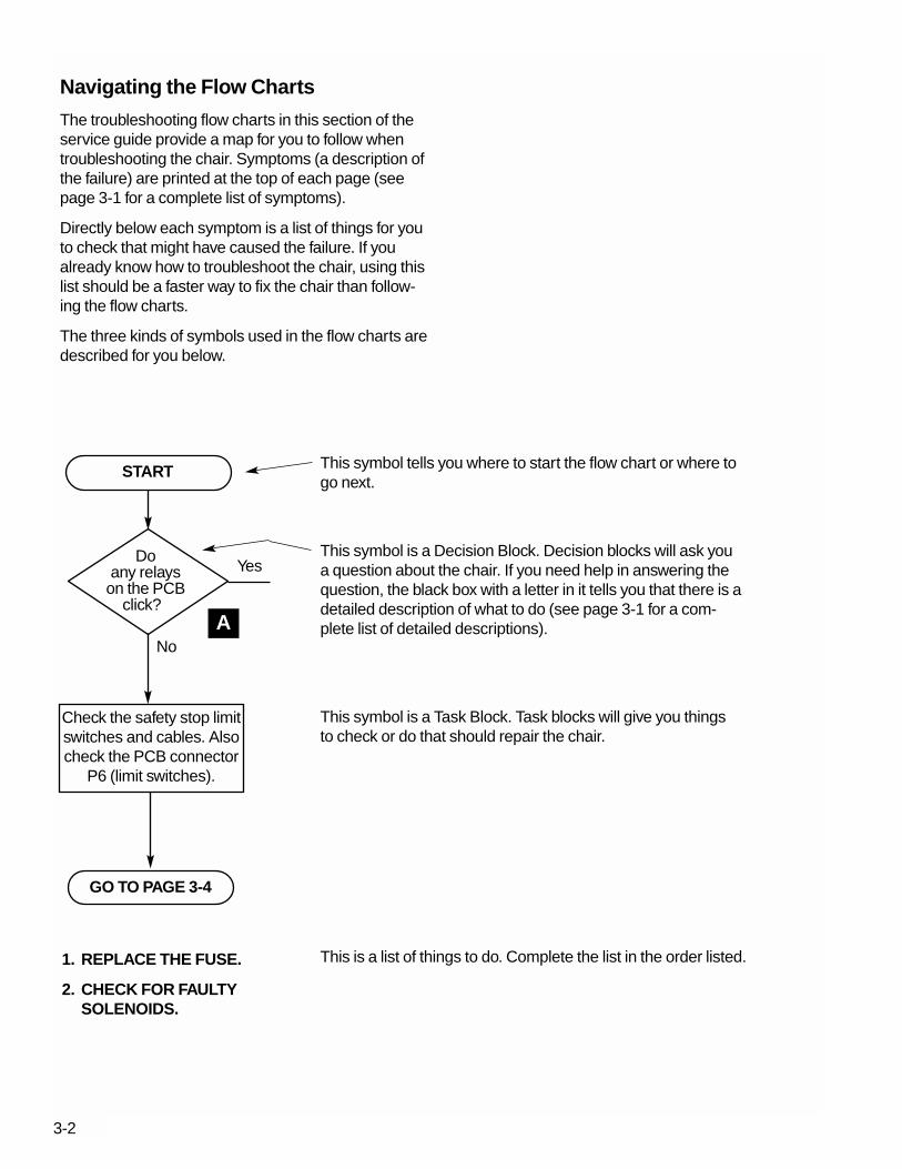
The troubleshooting flow charts in this section of theservice guide provide a map for you to follow whentroubleshooting the chair. Symptoms (a description ofthe failure) are printed at the top of each page (seepage 3-1 for a complete list of symptoms).
Directly below each symptom is a list of things for youto check that might have caused the failure. If youalready know how to troubleshoot the chair, using thislist should be a faster way to fix the chair than follow-ing the flow charts.
The three kinds of symbols used in the flow charts aredescribed for you below.
Doany relays
on the PCBclick?
Yes
No
Check the safety stop limitswitches and cables. Alsocheck the PCB connector
P6 (limit switches).
START
GO TO PAGE 3-4
This symbol tells you where to start the flow chart or where togo next.
This symbol is a Decision Block. Decision blocks will ask youa question about the chair. If you need help in answering thequestion, the black box with a letter in it tells you that there is adetailed description of what to do (see page 3-1 for a com-plete list of detailed descriptions).
This symbol is a Task Block. Task blocks will give you thingsto check or do that should repair the chair.
A
1. REPLACE THE FUSE.
2. CHECK FOR FAULTYSOLENOIDS.
This is a list of things to do. Complete the list in the order listed.
3-2

Chair is Inoperative
3-3
What to look for:A faulty base or back up limit switch.No power available to the chair.The chair is in hydraulic lock.A blown power or solenoid fuse.A faulty controller PCB or footswitch.
Hasthe solenoidfuse blown(120V only)
REPLACE THE FUSE. CHECK FORA SHORTED SOLENOID ORSHORTED WIRING TO THESOLENOIDS.
Doany relayson the PCB
click?
Is thebase/back all
the waydown?
Yes Yes
Yes
NoNo
No
Magneticpull at eachsolenoid?
Isthe chair in
hydraulic lock?
REMOVE AND REPLACETHE FAULTY SOLENOID.
No No
CHECK FOR ANDREPLACE A FAULTY
MANIFOLD OR VALVES.
YesDEPRESSURIZE THE HYDRAULICSYSTEM.
Yes
START
GO TO PAGE 3-5
GO TO PAGE 3-4
B
E
F
G
C

Chair is Inoperative
3-4
Is thePCB fuse
blown?
Yes
No
1. REMOVE AND REPLACE THE FUSE, THEN CHECK THEPOT WIRING FOR DAMAGE, SHORTS, OR IMPROPERWIRING.
2. IF THE FUSE BLOWS AGAIN, UNPLUG THE POT WIRINGAT P4 AND P5 ON THE PCB.
3. IF THE FUSE STILL BLOWS, REMOVE AND REPLACETHE PCB, OTHERWISE REMOVE AND REPLACE THEPOT WIRING.
1. CHECK CONDITION OF THE SAFETY STOP LIMITSWITCHES AND WIRING.
2. CHECK THE PCB CONNECTOR P6 (LIMIT SWITCHES).
3. UNPLUG THE CHAIR FROM IT'S POWER OUTLET ANDPLUG IT IN AGAIN.
4. IF THE CHAIR IS STILL INOPERATIVE, MAKE SURETHERE IS POWER AT THE OUTLET.
Yes
No
Doesthe chair
work ok now?
REMOVE AND REPLACE THE FOOTSWITCH.
THE PCB IS FAULTY, REMOVE AND REPLACE THE PCB.
Unplug the footswitch anduse the PCB test points toactivate chair up function.
CONTINUED FROM PAGE 3-3
A

Base or Back Up Function is Inoperative
What to look for:An overheated motor/pump.The solenoid fuse has blown.An open or faulty limit switch (LS).A faulty manifold/valve.The chair is in hydraulic lock.A faulty footswitch, motor capacitor, or controllerPCB.
Isthe chair
base or backup?
Is themotor/pump
hot?
Does arelay on PCB
click?
THE CHAIR MAY BE IN HYDRAULICLOCK, DEPRESSURIZE THEHYDRAULIC SYSTEM.
NORMAL CHAIR OPERATION, CHECKLIMIT SWITCH ADJUSTMENTS.
BASE SWITCH
Has theLS activated
(opened)?
Yes
Yes
Yes Yes
Yes
No
No
No No
No
1. WAIT 20 MINUTES FOR THERMAL LIMITER TO RESET.
2. IF THE UP FUNCTION WORKS, CHECK FOR OTHER PROBLEMS.
3. IF THE UP FUNCTION IS STILL INOPERATIVE.
SOLENOID IS FAULTY REPLACETHE SOLENOID.
Magneticpull at thesolenoid?
START
GO TO PAGE 3-6
GO TO PAGE 3-7
C I
G
EB
F
Hasthe solenoidfuse blown(120V only)
REPLACE THE FUSE.CHECK FOR A SHORTEDSOLENOID OR SHORTEDWIRING TO THESOLENOIDS.
Yes
No
3-5
C

Base or Back Up Function is Inoperative
3-6
Yes
Yes
No
No
No
No
Does arelay on PCB
click?
Yes
Yes
Does theup function
work?REPLACE THEFOOTSWITCH.
Magneticpull at thesolenoid?
Yes
NoFAULTY SOLENOID,REMOVE ANDREPLACE THESOLENOID.
REPAIR OR REPLACE THE LIMIT SWITCHWIRING.
Unplug the footswitch anduse the PCB test points toactivate chair up function.
Isthe LS
faulty oropen?
Is theLS wiring
faulty?
UNPLUG THE CHAIR AND PLUG IT BACKIN. IF THE PROBLEM REMAINS, THE PCBIS FAULTY, REPLACE THE PCB.
CONTINUED FROM PAGE 3-5
GO TO PAGE 3-7B
A
E
FC
C
ADJUST OR REMOVE AND REPLACETHE LIMIT SWITCH.
ADJUST THE BASE LSI

Base or Back Up Function is Inoperative
3-7
REPAIR THE MOTOR/CAPACITORWIRING.(Contact an A-dec representative for properrepair procedures.)
THE PCB IS FAULTY, REMOVEAND REPLACE THE PCB.
Open orshort in the
motor/capacitorwiring?
Is themotor current
morethan 5A?
FAULTY MOTOR/PUMP, REMOVEAND REPLACE THEMOTOR/PUMP ASSEMBLY.
No
No
No
No
Yes
Yes
Yes
1. REMOVE AND REPLACE THEMOTOR/PUMP CAPACITOR.
Yes
Is therenoise from
the motor/pump?
D
C
2. IF THE UP FUNCTION WORKSNOW, THE MOTOR/PUMPCAPACITOR WAS THE PROB-LEM, IF NOT THEN THE MANI-FOLD ASSEMBLY IS FAULTY,REMOVE AND REPLACE IT.
REPAIR OR REPLACE THE WIRING
ADJUST THE LIMIT SWITCH.
BASE SWITCHI
Is therean open in
the LSwiring ?
C
Is theLS out of
adjustment?
CONTINUED

Base or Back Down Function is Inoperative
3-8
What to look for:A Safety Stop switch or its wiring is open.A faulty footswitch or controller PCB.A blown solenoid fuse.The chair is in hydraulic lock.An improperly adjusted or faulty limit switch (LS).A faulty solenoid or valve.
Isthe baseor backstill up?
Does arelay on the PCB
click?
THE CHAIR MAY BE IN HYDRAULICLOCK, DEPRESSURIZE THEHYDRAULIC SYSTEM.
Has theLS
activated(opened)?
Yes
Yes Yes
YesNo
No No
No
REPLACE FAULTY MANIFOLD/VALVE.
REPLACE FAULTY SOLENOID.
Magneticpull at eachsolenoid?
Unplug the footswitch anduse the PCB test points toactivate the chair downfunction.
1. CHECK CONDITION OF SAFETY STOP AND/OR CUSPIDORLIMIT SWITCHES AND WIRING.
2. ALSO CHECK PCB CONNECTOR P6 (LIMIT SWITCHES).
3. UNPLUG THE CHAIR AND PLUG IT BACK IN. IF THE PROB-LEM REMAINS, THE PCB IS FAULTY, REPLACE THE PCB.
YesDoes thedown
functionwork?
REPLACE THE FOOTSWITCH.
Try an up function first,then down function.
No
START
C
G
EB
A Hasthe solenoidfuse blown(120V only)
Yes
No
REPLACE THE FUSE. CHECK FORAND REPLACE SHORTEDSOLENOID OR SHORTED WIRINGTO THE SOLENOIDS.
C
C
F
Unable to Program Auto-Positioning
3-9
Didthe chairprogram
ok?
No
Yes
Doeschair moveto wrongposition?
No
Yes
Doeschair move during
programming?
No
Yes
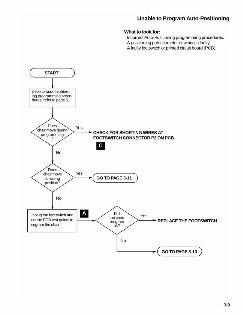
What to look for:Incorrect Auto-Positioning programming procedures.A positioning potentiometer or wiring is faulty.A faulty footswitch or printed circuit board (PCB).
Review Auto-Position-ing programming proce-dures, refer to page 5.
CHECK FOR SHORTING WIRES ATFOOTSWITCH CONNECTOR P2 ON PCB.
Unplug the footswitch anduse the PCB test points toprogram the chair.
REPLACE THE FOOTSWITCH
START
GO TO PAGE 3-11
GO TO PAGE 3-10
A
C

Unable to Program Auto-Positioning
3-10
Open orshort in
positioning potwiring?
No
Yes
Poor orreversed potconnections
?
No
Yes
PCB IS FAULTY, REPLACE THE PCB.
REPAIR POSITIONING POT WIRING.
REPAIR POSITIONING POT CONNECTIONS.
CONTINUED FROM PAGE 3-9
C

Incomplete Auto-Positioning Cycle
3-11
What to look for:The positioning pot wiring is damaged.Reversed or poor positioning pot connections.A positioning pot is damaged or in deadband.A positioning pot is not properly installed or adjusted.A faulty controller PCB.A new PCB that is not programmed for auto-positioning.A loose or damaged positioning pot mount.
Doesbase or back
travel time exceed40-45 sec
?
No
Yes
Is backstopping shortof full upright
?
No
Yes
ADJUST THE MANIFOLD METERINGSCREWS.
POSITIONING POT IS IN DEADBAND,ADJUST THE POT.
BASE POT
BACK POT
Has anew PCB been
installed?
No
Yes
Has anew pot been
installed?
No
Yes
RE-PROGRAM THE CHAIR PCB.
VERIFY THAT THE POSITIONING POTHAS BEEN INSTALLED CORRECTLY.
START
GO TO PAGE 3-12
H
J
K

Incomplete Auto-Positioning Cycle
3-12
Doesbase or backonly go in one
direction?
Yes
Doesbase or backgo in wrongdirection?
No
Yes
CHECK FOR FAULTY POSITIONING POTENTIOMETERS,WIRING, AND CONNECTIONS.
Dobase or back
shut off at sametime?
No
Is potresistance
0-5K Ω?
Potwiring &
connections = 0 Ω ?
PCB IS FAULTY, REPLACE THE PCB.
POSITIONING POT ISFAULTY, REPLACETHE POT.
REPAIR ORREPLACE THEWIRING ANDCONNECTIONS.
ON NEWER CHAIRS, TIGHTENTHE GEAR SETSCREW ANDTHEN ADJUST THE POT. ONOLDER CHAIRS, USE A GENER-AL PURPOSE INSTANT ADHE-SIVE TO GLUE THE GEAR ORHELIX DRIVE SHAFT TO THE POTSHAFT.
Is apot shaftslipping
?
Yes
No
No No
Yes
Yes Yes
No
CONTINUED FROM PAGE 3-11
GO TO PAGE 3-13
C C
J K
C

Incomplete Auto-Positioning Cycle
3-13
FAULTY PCB, REPLACE THE PCB.
CHECK FOR A LOOSE OR DAMAGED POTMOUNT OR IMPROPER ADJUSTMENT.
BASE SWITCH
BASE POT
BACK POT
Is apot shaftslipping
?
No
Arethe potsturning
?
Yes
No
Yes
CONTINUED FROM PAGE 3-12
I
ON NEWER CHAIRS, TIGHTEN THE GEARSETSCREW AND THEN ADJUST THE POT.ON OLDER CHAIRS, USE A GENERALPURPOSE INSTANT ADHESIVE TO GLUETHE GEAR OR HELIX DRIVE SHAFT TOTHE POT SHAFT.
J
K

Auto-Positioning Function Inoperative
3-14
Doesthe chairfunction
OK ?
No
YesFOOTSWITCH IS FAULTY, REPLACETHE FOOTSWITCH.
Doesthe chair go
to wrongposition?
No
Yes
UNPLUG THE CHAIR AND PLUG IT BACKIN. IF THE PROBLEM REMAINS, THE PCBIS FAULTY, REPLACE THE PCB.
What to look for:The positioning potentiometer wiring is faulty.A faulty printed circuit board (PCB).A positioning potentiometer is faulty.A faulty footswitch.
START
GO TO PAGE 3-11
Unplug the footswitch anduse the PCB test points toactivate the chair autofunction.
Re-program the chairwith new auto-position-ing settings
A

Back Moves for Base Only Functionor
Base Moves for Back Only Function
3-15
Is theproblem still
there?
No
Yes
FOOTSWITCH IS FAULTY, REPLACETHE FOOTSWITCH.
THE PCB IS FAULTY, REPLACE THE PCB.
What to look for:A faulty footswitch.A faulty printed circuit board (PCB).
START
Unplug the footswitch anduse the PCB test points toactivate the chair function.
A

3-17
Using the Chair Test Points A
The chair test points (see Figure 3-1) are used to testchair functions without a foot switch being connectedto the PCB. For example, if you short the two testpoints beside the Base Up (BS UP) label on the PCB,the chair base will move up if not already in the fullbase up position. To access the test points, you mustremove the motor/pump and PCB covers.
WARNING
HAZARDOUS AC VOLTAGES ARE PRESENTON THE PCB, DO NOT TOUCH ANY PART OFTHE PCB EXCEPT THE TEST POINTS.P
2
SW
1
TE
ST
PO
INT
SBK UP BK DN BS UP
EXDN
ENT
P1
NOTE: CONNECTORP1 OMITTED FORCLARITY.
Figure 3-1. Chair Test Points
Relay Click Test B
P2
SW
1
TE
ST
PO
INT
S
F2 3/10 ASLO BLOW
F1 1/8 ASLO BLOW
BK UP BK DN BS UP
EXDN
ENT
INP
UT
115/230V
12
34
56
87
S P
W60 H
Z
FU
SE
FU
SE
P1
Figure 3-2. PCB Relays
MOTORRELAY
BACK UPRELAY
BASE UPRELAY
BACK DOWNRELAY
BASE DOWNRELAY
If you listen when actuating any function on thefootswitch you should hear a clicking noise comingfrom the PCB. Figure 3-2 identifies the five relays onthe PCB by function. You can easily identify whichrelay is clicking, just note which function you haveactuated and if you hear a clicking noise the relay isbeing energized. The motor relay is energized only forup functions.
290101
290102

3-18
Continuity and Voltage TestsC
WARNING
HAZARDOUS AC VOLTAGES ARE PRESENTON THE PCB AND MOTOR/PUMP WIRING.FAILURE TO FOLLOW ALL SAFETY PRECAU-TIONS MAY RESULT IN SERIOUS INJURYFROM ELECTRICAL SHOCK.
Figure 3-3. Power Cord Continuity Test
Figure 3-4. Limit Switch Continuity Test
COMMON TERMINAL
SWITCH ARM
NORMALLYOPEN
NORMALLYCLOSED
Limit Switch Continuity Test
This test is applicable for testing either the Base Up orBack Up limit switches. For demonstration purposes,Figure 3-4 shows the Back Up limit switch.
1. Disconnect the wiring harness from the limitswitch. It isn't necessary to remove a limit switchfrom the chair for this test.
2. Touch a VOM probe to the common terminal (seeFigure 3-4) and the other probe to the normallyopen terminal and then to the normally closed ter-minal. The normally closed terminal should give areading of 1/2 ohm or less, the normally open ter-minal should read infinite (∞) resistance. If bothterminals indicate infinite resistance or indicate 1/2ohm or less, the switch is defective and must bereplaced.
3. If you are replacing a Base Up limit switch, com-plete the adjustment procedure on page 3-26.
Power Cord Continuity Test
1. Disconnect the power cord (J1) from the chairPrinted Circuit Board (PCB) (see Figure 3-3).
2. Touch a VOM probe to pin 1 of J1 and the otherprobe to first one and then the other blade of thepower plug. One blade should give a reading of1/2 ohm or less, the other blade should read infi-nite (∞) resistance. If both blades indicate infiniteresistance, the power cord is defective and mustbe replaced.
3. Touch a VOM probe to pin 3 of J1 and repeat steptwo above.
4. Touch a VOM probe to pin 2 of J1 and the otherprobe to ground on the plug. The resistanceshould be 1/2 ohm or less.
WARNING
MAKE CERTAIN POWER HAS BEEN REMOVEDFROM THE CHAIR BEFORE PROCEEDING.FAILURE TO REMOVE POWER FROM THECHAIR WILL RESULT IN SERIOUS INJURYFROM ELECTRICAL SHOCK OR DEATH.
J1
PIN 1
PIN 2
PIN 3
GROUND
290103
290104

3-19
Continuity and Voltage Tests (cont'd) C
Figure 3-6. Wiring Harness Continuity Test
Figure 3-5. Positioning Pot Continuity Test
POSITIONING POT
POSITIONING POTSHAFT AND GEAR
Positioning Potentiometer Continuity Test
This test is applicable for testing either the base orback positioning potentiometer (pot). For demonstra-tion purposes, Figure 3-5 shows the base positioningpot.
1. Disconnect the wiring harness from the positioningpot and remove the pot assembly from the chair.
2. Touch a VOM probe to an outside pin of the pot(see Figure 3-5) and the other probe to the otheroutside pin. The total resistance of the pot shouldbe approximately 4-6K Ω (5K Ω ±20%). If the potresistance is outside the limits, the pot is defectiveand must be replaced.
3. Move one VOM probe to the center pin of the pot.While observing the VOM, slowly turn the pot shaftfull one direction then the other. Your VOM shouldindicate a smooth increase or decrease in resis-tance as you turn the pot shaft. If the pot resis-tance fluctuates in a jerky manner while the shaftis being turned, the pot is defective and must bereplaced.
4. When installing a positioning pot, complete theadjustment procedures on page 3-28 for the backpositioning pot or page 3-27 for the base position-ing pot.
Wiring Harness Continuity Test
This test is applicable to testing a limit switch or posi-tioning potentiometer wiring harness assembly. Fordemonstration purposes, Figure 3-6 shows the BaseUp limit switch harness.
1. Disconnect the wiring harness from the limit switchor positioning potentiometer and the PCB. It isn'tnecessary to remove a wiring harness from thechair for this test.
2. Touch a VOM probe to pin 1 at one end of the har-ness (see Figure 3-6) and the other probe to pin 1at the other end of the harness. The VOM shouldgive a reading of 1/2 ohm or less. If the VOM indi-cates infinite or fluctuating resistance, the harnessis defective and must be replaced.
3. Repeat step 2 for each wire in the harness.
290105
290106

3-20
Continuity and Voltage Tests (cont'd)C
Figure 3-7. Positioning Pot Voltage Test
Figure 3-8. Switch Voltage Test
Limit and Safety Stop Switches
1. Disconnect the connector from the switch. Be sureto pull on the connector and not the wiring.
2. Touch a VOM probe to one pin of the connectorand the other to the remaining pin.
3. The voltage available should be approximately 5V(±1V). If the voltage is zero, the switch wiring har-ness or the chair PCB should be replaced.
Base and Back Positioning Pots
1. Touch the black probe of the VOM to the top pin ofthe pot and the red probe to the lower pin.
2. The voltage available should be approximately 5V(±1V). If the voltage is zero, the positioning potwiring harness or the chair PCB should bereplaced.
POSITIONING POT
Voltage Tests
The purpose of these tests is to verify that voltage isavailable at each of the limit switches and positioningpotentiometers (pots).
290107
290108

3-21
Continuity and Voltage Tests (cont'd) C
Solenoid Continuity Test
This test is applicable for testing 100, 120, and 240Vsolenoids.
1. Disconnect the solenoid wiring harness (J10) fromthe PCB (see Figure 3-9).
2. Touch a VOM probe to pin 5 of J10 and the otherprobe to the pin for the suspect solenoid (see Fig-ure 3-10). Refer to the table below for acceptableresistance tolerances. If the solenoid resistance isoutside the range specified, the solenoid is defec-tive and must be replaced.
Solenoid Resistance RangeP/N Voltage (Ω) (Ω)
61-1335-00 100V 220 200-25061-1336-00 120V 300 275-32561-1337-00 240V 1250 1100-1300
#1
#5, COMMON TO ALL SOLENOIDS
#3
#4
#2
BACK UPSOLENOID
(J10, #4)
BACK DOWNSOLENOID(HIDDEN)(J10, #1)
BASE UPSOLENOID
(J10, #3)
BASE DOWNSOLENOID
(J10, #2)
J10SOLENOID/MANIFOLDASSEMBLY
Figure 3-10. Solenoid Continuity Test
P2
SW
1
TE
ST
PO
INT
S
F2 3/10 ASLO BLOW
F1 1/8 ASLO BLOW
BK UP BK DN BS UP
EXDN
ENT
INP
UT
115/230V
12
34
56
87
S P
W60 H
Z
FU
SE
FU
SE
P1
Figure 3-9. Disconnect Solenoid Wiring Harness
TO MANIFOLD/SOLENOIDASSEMBLY
PRINTED CIRCUITBOARD (PCB)
J10
P10
290109
290110

3-22
Pump Motor TestD
Figure 3-11. Pump Motor Current Test
Figure 3-12. Testing Solenoids for Magnetic Pull
Testing Solenoids for Magnetic PullE
RED WIRE
WHITE WIRE
MOTOR/PUMP
MANIFOLD/SOLENOIDASSEMBLY
BACK DOWNSOLENOID(HIDDEN)
BACK UPSOLENOID
BASE UPSOLENOID
BASE DOWNSOLENOID
While holding the tip of a screwdriver near a solenoidas shown in Figure 3-12, activate the appropriate chairfunction. You should feel the tug of the magnetic fieldgenerated around the solenoid.
The Pump Motor Test requires the use of a currentpickup probe. Clip the probe onto the red wire going tothe motor/pump (see Figure 3-11) and activate a baseor back up function. You should read 5 Amps (maxi-mum) of current for this test (2.5 Amps for 240Vmotor/pumps).
290111
290112
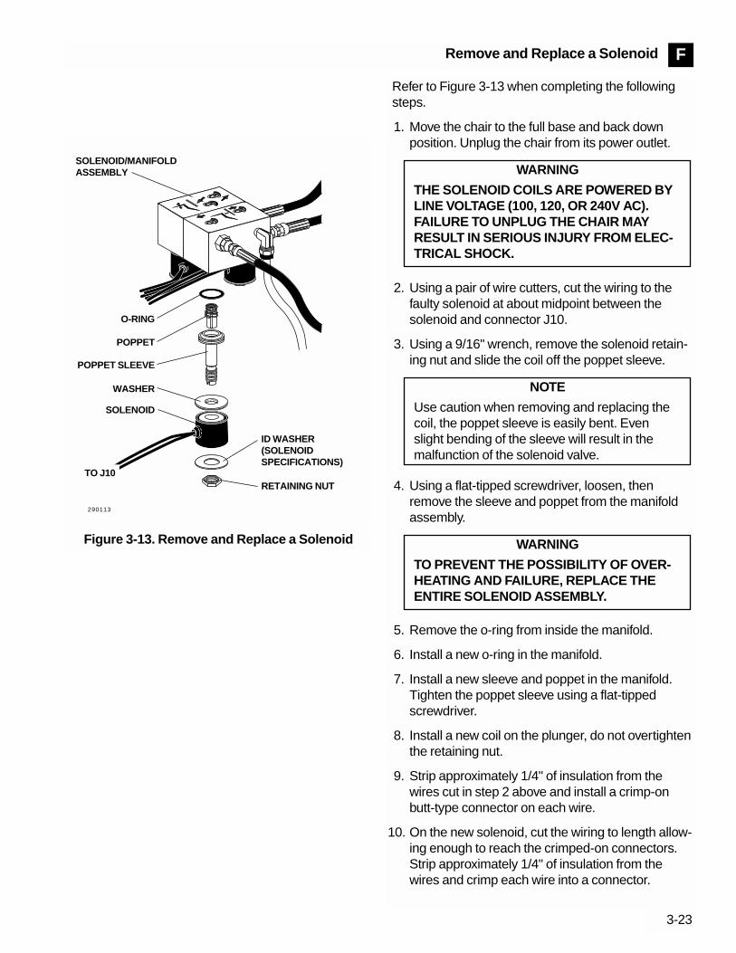
3-23
Remove and Replace a Solenoid F
Figure 3-13. Remove and Replace a Solenoid
290113
O-RING
POPPET
POPPET SLEEVE
WASHER
ID WASHER(SOLENOIDSPECIFICATIONS)
RETAINING NUT
SOLENOID
SOLENOID/MANIFOLDASSEMBLY
TO J10
Refer to Figure 3-13 when completing the followingsteps.
1. Move the chair to the full base and back downposition. Unplug the chair from its power outlet.
2. Using a pair of wire cutters, cut the wiring to thefaulty solenoid at about midpoint between thesolenoid and connector J10.
3. Using a 9/16" wrench, remove the solenoid retain-ing nut and slide the coil off the poppet sleeve.
4. Using a flat-tipped screwdriver, loosen, thenremove the sleeve and poppet from the manifoldassembly.
5. Remove the o-ring from inside the manifold.
6. Install a new o-ring in the manifold.
7. Install a new sleeve and poppet in the manifold.Tighten the poppet sleeve using a flat-tippedscrewdriver.
8. Install a new coil on the plunger, do not overtightenthe retaining nut.
9. Strip approximately 1/4" of insulation from thewires cut in step 2 above and install a crimp-onbutt-type connector on each wire.
10. On the new solenoid, cut the wiring to length allow-ing enough to reach the crimped-on connectors.Strip approximately 1/4" of insulation from thewires and crimp each wire into a connector.
WARNING
TO PREVENT THE POSSIBILITY OF OVER-HEATING AND FAILURE, REPLACE THEENTIRE SOLENOID ASSEMBLY.
NOTE
Use caution when removing and replacing thecoil, the poppet sleeve is easily bent. Evenslight bending of the sleeve will result in themalfunction of the solenoid valve.
WARNING
THE SOLENOID COILS ARE POWERED BYLINE VOLTAGE (100, 120, OR 240V AC).FAILURE TO UNPLUG THE CHAIR MAYRESULT IN SERIOUS INJURY FROM ELEC-TRICAL SHOCK.
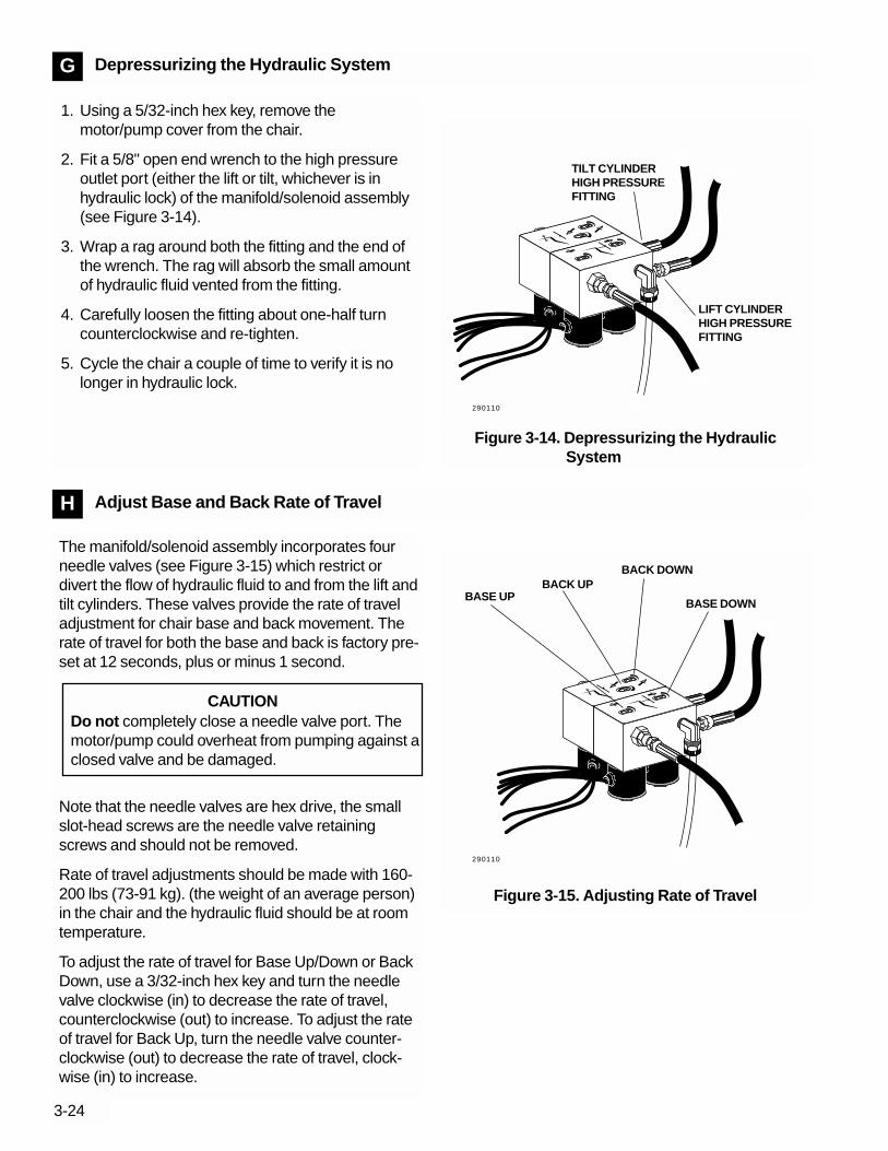
3-24
Depressurizing the Hydraulic SystemG
Adjust Base and Back Rate of TravelH
1. Using a 5/32-inch hex key, remove themotor/pump cover from the chair.
2. Fit a 5/8" open end wrench to the high pressureoutlet port (either the lift or tilt, whichever is inhydraulic lock) of the manifold/solenoid assembly(see Figure 3-14).
3. Wrap a rag around both the fitting and the end ofthe wrench. The rag will absorb the small amountof hydraulic fluid vented from the fitting.
4. Carefully loosen the fitting about one-half turncounterclockwise and re-tighten.
5. Cycle the chair a couple of time to verify it is nolonger in hydraulic lock.
LIFT CYLINDERHIGH PRESSUREFITTING
TILT CYLINDERHIGH PRESSUREFITTING
Figure 3-14. Depressurizing the HydraulicSystem
The manifold/solenoid assembly incorporates fourneedle valves (see Figure 3-15) which restrict ordivert the flow of hydraulic fluid to and from the lift andtilt cylinders. These valves provide the rate of traveladjustment for chair base and back movement. Therate of travel for both the base and back is factory pre-set at 12 seconds, plus or minus 1 second.
Note that the needle valves are hex drive, the smallslot-head screws are the needle valve retainingscrews and should not be removed.
Rate of travel adjustments should be made with 160-200 lbs (73-91 kg). (the weight of an average person)in the chair and the hydraulic fluid should be at roomtemperature.
To adjust the rate of travel for Base Up/Down or BackDown, use a 3/32-inch hex key and turn the needlevalve clockwise (in) to decrease the rate of travel,counterclockwise (out) to increase. To adjust the rateof travel for Back Up, turn the needle valve counter-clockwise (out) to decrease the rate of travel, clock-wise (in) to increase.
CAUTIONDo not completely close a needle valve port. Themotor/pump could overheat from pumping against aclosed valve and be damaged.
Figure 3-15. Adjusting Rate of Travel
BASE UPBACK UP
BASE DOWN
BACK DOWN
290110
290110

3-25
Adjust the Base Up Limit Switch I
To adjust the base up limit switch:
1. Using a 5/32-inch hex key, remove the threescrews securing the motor/pump cover to the chairand set the cover aside.
2. Using a 3/32-inch hex key, loosen the two screwsclamping the limit switch to the mounting bracket(see Figure 3-16).
3. Position the chair as shown in Figure 3-17. Mea-sure from the top of the base plate to the flat areaaround the threaded stud the chair adaptermounts to.
4. Push the limit switch against the actuator pin (seeFigure 3-16) on the drive gear until the switchopens (clicks), then tighten the clamping screws.
5. Position the chair base down until the limit switchhas closed, then position the chair full base up.Check the distance between top of the base plateto the flat area around the threaded stud the chairadapter mounts to. If the distance isn't correct,repeat steps 2 through 4.Figure 3-16. Adjust the Base Up Limit Switch
LIMIT SWITCH
SWITCH ARM
CLAMPING SCREWS
MOUNTINGBRACKET
ACTUATOR PIN
NOTE: POSITIONING POTASSEMBLY OMITTEDFOR CLARITY.
Figure 3-17. Setting Chair Height
23"58.4cm
25"63.5cm
Model 1010 Model 1015 and 1020
290098
290068290001

3-26
To adjust the base positioning potentiometer (pot):
1. Using a 5/32-inch hex key, remove themotor/pump cover and set the cover aside.
2. Position the chair as shown in Figure 3-17. Mea-sure from the top of the base plate to the flat areaaround the threaded stud the chair adaptermounts to.
3. Using a 3/16-inch hex key, remove the limit switchand pot assembly mounting screw (see Figure 3-18).
4. Turn the gear on the pot shaft counterclockwiseuntil it stops (see Figure 3-18).
5. Align the pot assembly as shown in Figure 3-18then turn the pot drive gear clockwise two teeth(relative to a tooth on the large drive gear).
6. Reinstall the limit switch and pot assembly Makesure that the pot gear does not turn and that thetwo gears mesh properly.
7. Check the electrical connections to the limit switchand positioning pot, make sure the connectionsare proper.
8. While observing the two gears for binding, lowerthe chair base. Do not raise the base to full baseup until after you've checked the base up limitswitch for proper adjustment, the chair may go intohydraulic lock.
9. Reinstall the motor/pump cover.
10. Program the auto-positioning functions.
Adjust the Base Positioning PotentiometerJ
CLOCKWISE
COUNTERCLOCKWISE
MOUNTING SCREW POSITIONINGPOT
LARGE DRIVE GEAR
POT DRIVEGEAR
Figure 3-18. Adjust the Base Positioning Pot
290114

3-27
Adjust the Back Positioning Potentiometer K
To adjust the back positioning (pot) potentiometer:
1. Position the chair back full down.
2. Lift the toeboard and swing the roller bar assemblyup under the hook welded to the underside of thetoeboard. Lower the toeboard hook onto the rollerbar assembly.
3. Using a 3/16-inch hex key, remove the positioningpot assembly mounting screws (see Figure 3-19).
4. Remove the positioning pot assembly and helicaldrive shaft from the chair.
5. Pull the helical drive shaft off the pot shaft.
6. Install the helical drive shaft in the chair as shownin Figure 3-20.
7. Turn the positioning pot full counterclockwise (seeFigure 3-21).
8. Reinstall the pot assembly on the helical driveshaft.
9. Check the electrical connections to the limit switchand positioning pot, make sure the connectionsare proper.
10. Reprogram the auto-positioning functions.
Figure 3-19. Back Positioning Pot Assembly
MOUNTING SCREWS
Figure 3-20. Install the Pot Drive Shaft Figure 3-21. Setting the Back Positioning Pot
COUNTERCLOCKWISE
HELICAL DRIVE SHAFT
290115
290116290117

3-28
Adjust Auto PositioningMultifunction Footswitch
L
Adjust Auto Positioning8 Function Footswitch
L
Using the footswitch, set the chair to the desired posi-tion. For chairs manufactured prior to December 21,1990, insert a probe that is approximately 3/l6–inch indiameter and 3 inches long into the hole located onthe right side of the motor compartment cover (seeFigure 3-22). Momentarily push the probe in gently(actuating the store button) and, within four seconds,press the GREEN (Pre–Position) or RED(Auto–Return) button on the foot switch to store theposition.
Chair S/N L086602 and newer have a rubber grom-met–type button which eliminates the need for aprobe to actuate the auto–positioning store button.
Later chairs include an audible tone generator. Anaudible tone confirms programming operations.
Using the footswitch, set the chair to the desired posi-tion. Press and release the program button (see Fig-ure 3-22A). An audible tone will be heard. Within fourseconds, press the right actuator (see Figure 3-22A)to the function (1, 2 or 3) you want this chair positionto be stored. Now you should hear an audible toneconfirming that the function has been programmed.
Figure 3-22. Programming the Chair
RED BUTTON
GREEN BUTTON
STORE BUTTON ACCESSHOLE OR RUBBER GROM-MET–TYPE BUTTON
FOOTSWITCH
290007
290052
Figure 3-22A. Programming the Chair
123
0
FOOTSWITCH
PROGRAM BUTTON
RIGHT ACTUATOR
LEFTACTUATOR

3-29
Function 3 can optionally be either Cuspidor/Return,Last Position, or a user programmable function.
Cuspidor/Return is used to raise the chair back to aprogrammable upright position providing the patientaccess to the cuspidor. Momentarily pushing the rightactuator to position 3 a second time lowers the chairback to its previous operating position.
Last Position is a non-programmable function thatsimply moves the chair base and back to the posi-tions that they were in previously. Using this featureallows the chair to be moved back and forth betweentwo positions by momentarily pushing the right actua-tor to position 3.
Switches S1 and S2 on the circuit board is used toselect the function for Function 3.
Function Switch 1 Switch 2
Cuspidor/Return OFF OFFLast Position ON OFFUser Programmable OFF ON
Adjust Headrest Glidebar Tension M
Using a Phillips screwdriver, adjust the glide bar ten-sion (see Figure 3-23). Turn the screw clockwise toincrease friction and hold the headrest more securely.Turn it counterclockwise to decrease friction and allowthe headrest to move up and down more freely. Adjustthe glide bar tension so that the headrest movesfreely yet maintains it position.
Figure 3-23. Adjusting Headrest Glidebar Tension
TENSIONADJUSTMENTSCREW
290118
Figure 3-22B. Programming the Chair
ON
12
S1
S2
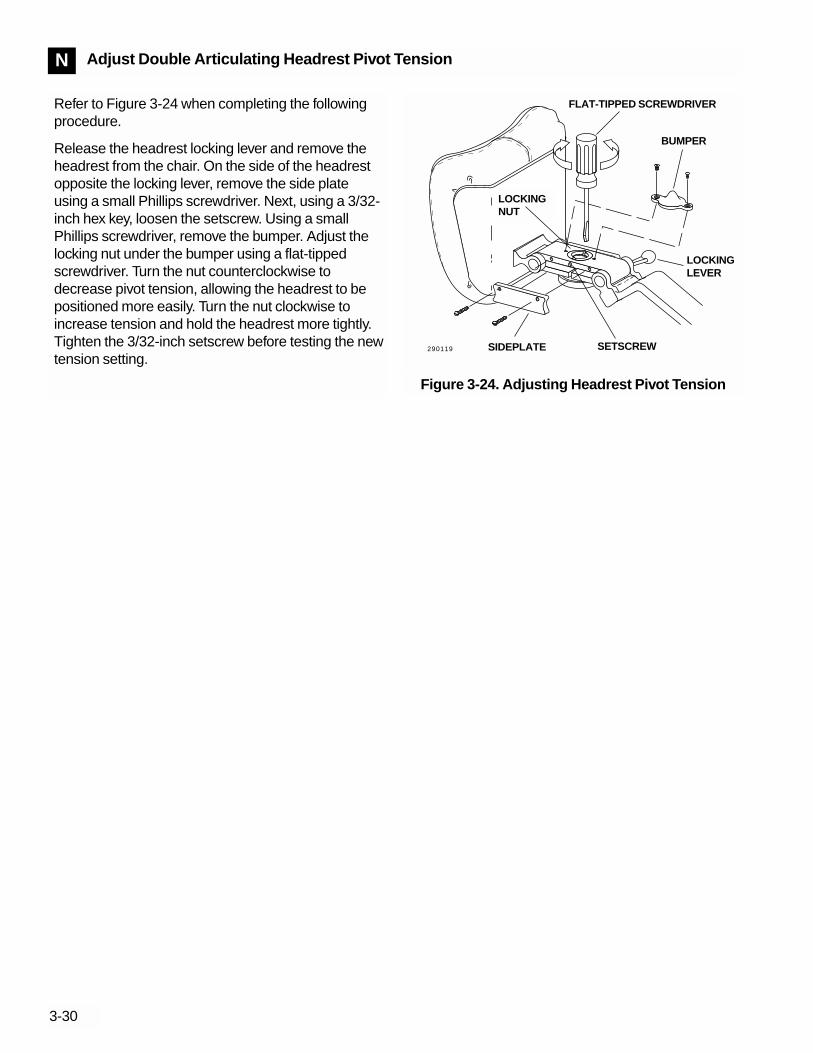
3-30
Adjust Double Articulating Headrest Pivot TensionN
Refer to Figure 3-24 when completing the followingprocedure.
Release the headrest locking lever and remove theheadrest from the chair. On the side of the headrestopposite the locking lever, remove the side plateusing a small Phillips screwdriver. Next, using a 3/32-inch hex key, loosen the setscrew. Using a smallPhillips screwdriver, remove the bumper. Adjust thelocking nut under the bumper using a flat-tippedscrewdriver. Turn the nut counterclockwise todecrease pivot tension, allowing the headrest to bepositioned more easily. Turn the nut clockwise toincrease tension and hold the headrest more tightly.Tighten the 3/32-inch setscrew before testing the newtension setting.
Figure 3-24. Adjusting Headrest Pivot Tension
SETSCREW
LOCKINGLEVER
SIDEPLATE
BUMPER
FLAT-TIPPED SCREWDRIVER
LOCKINGNUT
290119

Service Parts Codes
Section 4, Illustrated Parts Breakdown (IPB), includesService Parts Codes in the right hand column of everyparts list (see Figure 4-1). Service Parts Codes helpyou determine what parts should be kept on hand andaid you in locating those parts when they are needed.
Service Parts Codes are defined as follows:
Code 1: Hardware Store Items
Parts designated as Code 1 are those items thatcan be purchased at retail hardware stores inmost parts of the United States. Service delaysare minimized when these parts are obtainedlocally. In areas where Code 1 parts are not avail-able, they can be ordered from A-dec.
Code 2: Field Repair Kit
Code 2 parts are included in an A-dec FieldRepair Kit when available. Currently a field repairkit for A-dec Models 1010/15/20 Dental Chairs isnot available.
Code 3: Service Vehicle Parts Stock
Code 3 parts are items we suggest you carry inyour service vehicle. A-dec does not offer a Code3 parts kit as service requirement quantities varyin different areas. Select and stock Code 3 partsthat satisfy the needs of your area.
Code 4: Dealer Shelf Stock
Code 4 parts are those that, in addition to Code 2and 3 parts, should be stocked by the dealer.
Code 5: Factory Order
Code 5 parts are readily available from A-dec. These parts are not needed frequentlyenough to justify keeping them in stock at thedealer.
Code 6: Not Available for Field Replacement
Code 6 parts are not available (N/A) for fieldreplacement or must be ordered as part of a larg-er assembly.
4-1
Figure 4-1. Service Parts Code Column
SERVICE PARTS CODE COLUMN
PART NO. CODE
SECTION 4ILLUSTRATED PARTS
BREAKDOWN

Figure 4-2. 1015/20 Lower Covers
4-2
13E3D3C3B3A 2
3 4 5 6 7 8 9
Ref.No. Description Part No. Code
1 Screw, Btn Hd Soc 1/4-20 X 5/8, Nkl 005-002-01 12 Retainer, Safety Plate 61-1401-00 43 Cover Assy, Lift Arm, Lower, 1015/20 61-1397-00 43A Cover, Lift Arm, Lower, 1015/20 61-1398-00 43B Mounting Bracket, Lower Cover, LH 61-1400-00 53C Mounting Bracket, Lower Cover, RH 61-1399-00 53E Rivet, Pop, 3/16” Steel 012-011-00 44 Screw, Btn Hd Soc 1/4-20 X 3/8, Nkl 005-112-00 15 Cover, Lift Arm, Rear, 1015/20 61-1396-00 46 Screw, Btn Hd Soc 1/4-20 X 5/8, Nkl 005-002-01 17 Cover, Lift Arm, Upper, 1015/20 61-1395-00 48 Cover, Hydraulic Pump, Vac-Back 1015/20 61-1441-00 48 Cover, Hydraulic Pump 61-1204-00 49 Screw, Btn Hd Soc 1/4-20 X 3/8, Nkl 005-112-00 1
Table 4-1. 1015/20 Lower Covers Parts list
290083
290120

4-3
Figure 4-3. 1015/20 Safety Stop Bracket and Switches
Ref.No. Description Part No. Code
1 Screw, Soc Head, 4-40 X 1/2, SST 001-021-00 12 Limit Switch, Modified 044-049-01 33 Mounting Bracket, Sw, Safety Plate 61-1411-00 54 Screw, Soc Head, 1/4-20 X 1/2, Zinc 005-008-00 55 Spacer, .625 Long X .31 OD, Brass 61-1413-00 56 Screw, Button Head Soc, 1/4-20 X 1 Nkl 005-109-01 57 Baseplate, 1010/15/20 Chair, Gray 61-1275-00 5
Baseplate, 1010/15/20 Chair, Surf #6 61-1275-01 5
Not ShownCable Assy, Lift, Tilt, Safety Switch, 1015/20/40 61-2099-00 3
Cable Assy, Lift, Tilt, 1010 61-1220-00 3
Table 4-2. 1015/20 Safety Stop Bracket and SwitchesParts List
1
2
3
4
5
7
6
290090
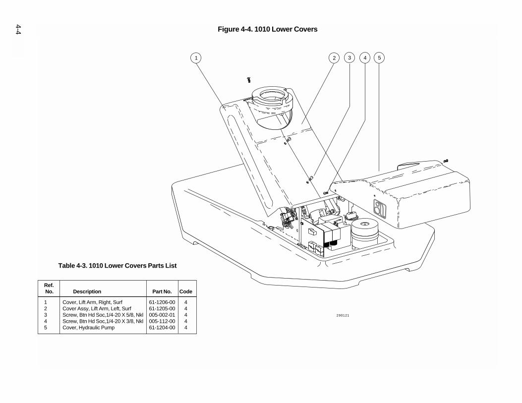
4-4 Figure 4-4. 1010 Lower Covers
2 3 4 51
Ref.No. Description Part No. Code
1 Cover, Lift Arm, Right, Surf 61-1206-00 42 Cover Assy, Lift Arm, Left, Surf 61-1205-00 43 Screw, Btn Hd Soc,1/4-20 X 5/8, Nkl 005-002-01 44 Screw, Btn Hd Soc,1/4-20 X 3/8, Nkl 005-112-00 45 Cover, Hydraulic Pump 61-1204-00 4
Table 4-3. 1010 Lower Covers Parts List
290121
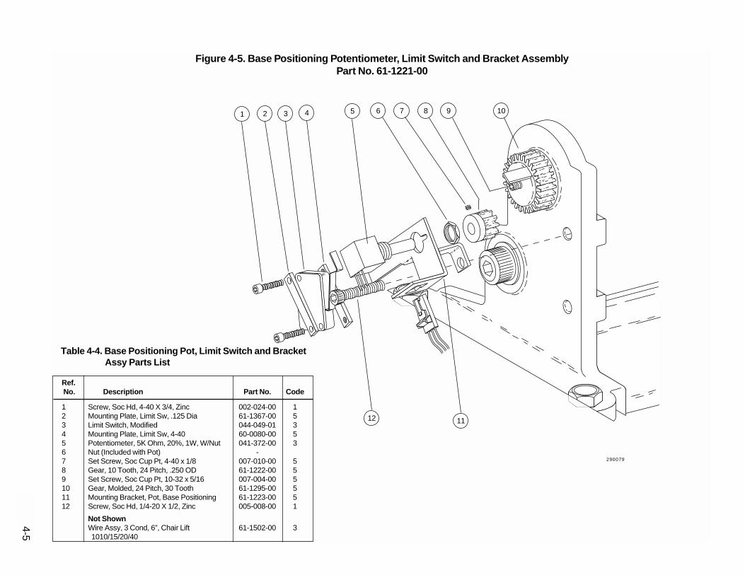
4-5
1 2 3 4 5 6 7 8 9 10
1112
Ref.No. Description Part No. Code
1 Screw, Soc Hd, 4-40 X 3/4, Zinc 002-024-00 12 Mounting Plate, Limit Sw, .125 Dia 61-1367-00 53 Limit Switch, Modified 044-049-01 34 Mounting Plate, Limit Sw, 4-40 60-0080-00 55 Potentiometer, 5K Ohm, 20%, 1W, W/Nut 041-372-00 36 Nut (Included with Pot) -7 Set Screw, Soc Cup Pt, 4-40 x 1/8 007-010-00 58 Gear, 10 Tooth, 24 Pitch, .250 OD 61-1222-00 59 Set Screw, Soc Cup Pt, 10-32 x 5/16 007-004-00 510 Gear, Molded, 24 Pitch, 30 Tooth 61-1295-00 511 Mounting Bracket, Pot, Base Positioning 61-1223-00 512 Screw, Soc Hd, 1/4-20 X 1/2, Zinc 005-008-00 1
Not ShownWire Assy, 3 Cond, 6”, Chair Lift 61-1502-00 31010/15/20/40
Table 4-4. Base Positioning Pot, Limit Switch and BracketAssy Parts List
Figure 4-5. Base Positioning Potentiometer, Limit Switch and Bracket AssemblyPart No. 61-1221-00
290079
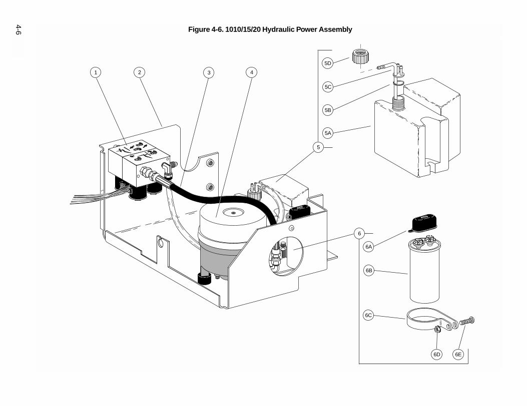
4-6 Figure 4-6. 1010/15/20 Hydraulic Power Assembly
1 2 3 4
5
6
5D
5C
5B
5A
6A
6B
6C
6D 6E

Ref.No. Description Part No. Code
1 Manifold Assy, Hyd, 100V, 1010/15/20 Chair 61-1332-00 4Manifold Assy, Hyd, 120V, 1010/15/20 Chair 61-1333-00 4Manifold Assy, Hyd, 240V, 1010/15/20 Chair 61-1334-00 4
2 Mounting Tray, Hydraulic Power 61-1338-00 53 Hose Assy, Hyd, Str/Str Ends, 12.75 Long 61-0109-03 34 Motor Assy, Hyd Pump, 100V 61-1326-00 4
Motor Assy, Hyd Pump, 115V 61-1327-00 4Motor Assy, Hyd Pump, 240V 61-1328-00 4
5A Tank, Hydraulic, 1010 Chair 61-1339-00 45B Washer, Flat, Buna-N, .75 ID 004-161-00 45C Pick-Up Tube Assy, Hydraulic Tank 61-1489-00 45D Nut, Retainer, 3/4 Garden Hose Thread 006-112-00 46A Capacitor, 50 Uf, 240 VAC, 60 Hz 041-164-00 36B Boot, Protective, Capacitor 041-165-00 56C Clamp, Capacitor Mounting 025-058-00 56D Nut, Hex, KEPS, 10-32 X 3/8 X 5/32 006-016-00 16E Screw, Btn Hd Soc, 10-32 X 1/2, SST 005-110-00 1
Not ShownTubing 3/8” OD, Hydraulic Fluid, 8” Length 036-035-00 3Hose Assy, Hyd, Str/Str Ends, 27.25 Lg 61-0109-02 3Hose Assy, Hyd, Str/90 Deg Ends, 52” Lg 61-0217-03 3Circuit Board Assy, 1010 Chair 120V 61-1214-01 3Circuit Board Assy, 1010 Chair 240V 61-1217-01 3Circuit Board Assy, 1010 Chair 100V 61-1373-01 3Fuse, 1/8 A, 250V, 3AG, Slow-Blow 041-360-00 3Fuse, 0.3 A, 250V, 3AG, Slow-Blow 046-069-00 3Wire Assy, 3 Cond, 48", Chair Back 61-1503-00 3Cable Assy, Lift & Tilt Limit Switches, Sankin 61-1366-00 3Air Elec Sw/Cable Assy, 1010, Sankin 61-1384-00 3
4-7
Table 4-5. 1010/15/20 Hydraulic Power Assembly Parts List

4-8 Figure 4-7. Hydraulic Manifold/Solenoid Assembly
1A
1
2
3
4
5
1B
1C
1D
1E
1F
1G
6
7
8
9
11
10
12
13
14
15
16
17
18
290023290024

4-9
Ref.No. Description Part No. Code
1 Solenoid, 8 Watt, 100V 61-1335-00 3Solenoid, 8 Watt, 120V 61-1336-00 3Solenoid, 8 Watt, 240V 61-1337-00 3
1A O-Ring, AS568-016, .614 ID X .070 W 030-016-00 31B Plunger and Spring, Solenoid - 61C Plunger Guide, Solenoid - 61D Washer, Solenoid - 61E Solenoid - 61F Nameplate, Solenoid - 61G Nut, Solenoid - 62 Manifold, Tilt - 63 Washer, Flat, STL PL, .156 ID 004-012-00 34 Screw, Soc Hd, 6-32 X 1-3/4, Blk 002-101-00 15 Decal, Speed Adj., Tilt 055-122-00 56 Screw, Tr Hd Slot, 2-56 X 1/8 SST 001-002-00 57 Screw, Flow Adjust, 10-56 61-0460-00 38 Decal, Speed Adj., Lift 055-121-00 59 O-Ring, AS568-010, .239 ID X .070 W 030-010-00 310 Manifold, Lift - 611 Ftg W/O-Ring, JIC, 37 Deg Str Thrd 022-049-00 412 Spring, Helical, Comp, .250 OD X .40 013-044-00 413 Stem W/O-Ring, Check Valve 61-0461-00 414 O-Ring, AS568-004, .070 ID X .070 W 030-004-00 315 Elbow, 3/8 Poly X 1/8 MPT 022-025-00 416 Screen, Manifold Inlet 61-0464-00 317 Ftg W/O-Ring, JIC, 37 Deg Str Thrd 022-049-00 418 Screen, Manifold Outlet 61-0465-00 3
Table 4-6. Hydraulic Manifold/Solenoid Assembly Parts List

4-10
1
2
Figure 4-8. Base Lift and Back Tilt Hydraulic Cylinders
Ref.No. Description Part No. Code
1 Tilt Cylinder Assembly 61-1267-00 32 Lift Cylinder Assembly 61-1287-00 3
Table 4-7. Base Lift and Back Tilt Hydraulic CylindersParts List
290095
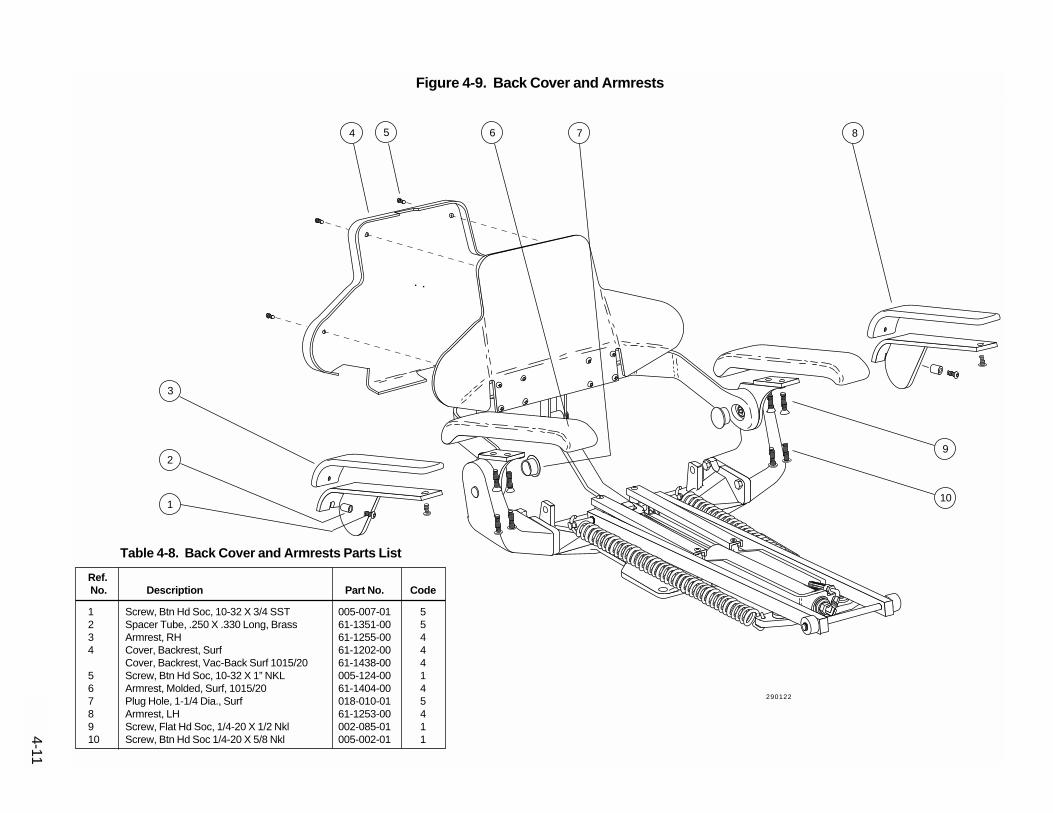
4-11
Figure 4-9. Back Cover and Armrests
3
4 5 6 7 8
Ref.No. Description Part No. Code
1 Screw, Btn Hd Soc, 10-32 X 3/4 SST 005-007-01 52 Spacer Tube, .250 X .330 Long, Brass 61-1351-00 53 Armrest, RH 61-1255-00 44 Cover, Backrest, Surf 61-1202-00 4
Cover, Backrest, Vac-Back Surf 1015/20 61-1438-00 45 Screw, Btn Hd Soc, 10-32 X 1” NKL 005-124-00 16 Armrest, Molded, Surf, 1015/20 61-1404-00 47 Plug Hole, 1-1/4 Dia., Surf 018-010-01 58 Armrest, LH 61-1253-00 49 Screw, Flat Hd Soc, 1/4-20 X 1/2 Nkl 002-085-01 110 Screw, Btn Hd Soc 1/4-20 X 5/8 Nkl 005-002-01 1
Table 4-8. Back Cover and Armrests Parts List
1
29
10
290122

4-12 Figure 4-10. Upper Structure
1 2 3 4
5
6
7
8
9
12
11
10
13
14
Ref.No. Description Part No. Code
1 Frame, Upper Structure - 62 Screw, Soc Hd, 1/4-20 X 1/2, Zinc 005-008-00 13 Link Arm, Roller, Toeboard - 64 Channel, Guide, Slide Block - 65 Tilt Cylinder Assy 61-1267-00 36 Hose Assy, Hyd, Str/90 Deg Ends, 52” Lg 61-0217-03 37 Retaining Ring, Ext, E-Ring, 1.00 Dia 010-051-00 18 Screw, Soc Hd, 1/4-20 X 3/4, Zinc 002-080-00 19 Pad, Wear, Link Arm 61-1314-00 510 Nut, Hex, 1/4-20 X 7/16 X 3/16, Stl 006-023-00 111 Tilt, Spacer F84-705 312 Pad, Wear, Link Arm F84-706 513 Screw, Soc Hd, 1/4-20 X 1 3/4, Zinc 002-050-00 114 Spring, Helical, Ext, 1.25 OD X11.0 Lg 013-054-00 5
Table 4-9. Upper Structure Parts List
290091

4-13
Figure 4-11. Back Positioning Potentiometer, Limit Switch and Bracket Assembly
1
2
3
4
5 6
6A
6B
6C
6F
6E
6D
Ref.No. Description Part No. Code
1 Screw, Soc Hd, 4-40 X 3/4, Zinc 002-024-00 12 Limit Switch, Modified 044-049-01 33 Screw, Soc Hd, 1/4-20 X 1/2, Zinc 005-008-00 14 Bracket, Upper Structure L37-385 55 Mounting Bracket, Limit Sw, Tilt 61-1315-00 56 Potentiometer & Brkt Assy, Back Positioning 61-1224-00 36A Pin, Spring, .125 Dia X .75 Lg, STL 011-035-00 56B Drive Shaft, Helical, 8.00 Lg 61-1225-00 56C Tubing, Yellow, Urethane, 3/8 OD 036-031-00 56D Screw, Soc Hd, 1/4-20 X 1/2, Zinc 005-008-00 16E Potentiometer, 5K Ohm, 20%, 1W, W/Nut 041-372-00 36F Mounting Bracket, Pot, Back Pos 61-1226-00 5
Table 4-10. Back Positioning Pot, Limit Switch and Bracket Assy Parts List
290066

Figure 4-12. Headrest Glidebar Brake Assemblies
2
1
2A
2B
2C
2D
2E
3
3A
3B
3C
Ref.No. Description Part No. Code
1 Screw, Btn Hd Soc, 10-32 X 1/2, SST 005-110-00 32 Sliding Wedge Assy, Glide Bar, 1010 61-1570-00 52A Guide Block, Headrest, Molded 61-1568-00 52B Nut, Hex, 10-32 X 3/8 X 1/8 STL 006-081-00 12B Screw, Pan Hd Phil, 10-32 X 1-3/4” 001-161-00 12C Wear Pad, Sliding Wedge, Molded 61-1569-00 52D Sliding Wedge, Tension Adjust Molded 61-1572-00 52E Spring, Headrest Tension, Molded 61-1571-00 53 Headrest Glidebar Brake Assembly - 63A Nut, Hex, 10-32 X 3/8 X 1/8 STL 006-002-00 13A Screw, Pan Hd Phil, 10-32 X 1-3/4” 001-161-00 13B Sliding Wedge Assy - 63C Guide Block, Glide Bar, Headrest - 6
Table 4-11. Headrest Glidebar Brake Assemblies Parts List
4-14
290089
290090

4-15
Figure 4-13. Vac Back Manifold and Pivot Arm Leveling Assembly
1 2 3
4
7
89
5
6
Ref.No. Description Part No. Code
1 Weldment, Backrest 1010/1015 Chair - 6Weldment, Backrest, Vac-Back, 1015 - 6
2 Manifold Assy, Vac-Back, PE 61-1022-00 33 Screw, Soc Hd, 10-32 X 3/8, Zinc 001-016-00 54 Link, Pivot Arm, Vac-Back, 1015 61-1448-00 15, 7 Retaining Ring, External E-Ring.25 Dia 010-053-00 16, 8 Retaining E-Ring, External, 1/2” ID 010-031-00 19 Screw, Soc Hd, 1/4-20 X 3/4, Zinc 002-080-00 1
Table 4-12. Vac Back Manifold and Pivot Arm Leveling AssyParts List
290085

Figure 4-14. Vac Back Cover and Pivot Arm Assembly
123
3A3B3C3D3E
45678910111213
4-16
290085

Ref.No. Description Part No. Code
1 Screw, Btn Hd Soc, 10-32 X 1” NKL 005-124-00 12 Grommet, 3/8 ID X 3/16 Groove Wide 018-040-00 53A Washer, Flat, Nylon, .252 ID 004-139-00 53B Race, Thrust .252 ID 016-053-00 53C Bearing, Thrust Needle, .252 ID 016-054-00 53D Race, Thrust .252 ID 016-053-00 53E Screw, Btn Hd Soc, 1/4-20 X 1 NKL 005-109-01 5
Screw, Btn Hd Soc, 1/4-20 X 1 Zinc 005-109-00 14 Washer, Flat, Nylon, .252 ID 004-139-00 15 Washer, Flat, Nylon, .503 ID 004-140-00 56 1” Dia Arm Assy, Vac-Back, Crm Pnt - 67 Set Screw, Soc Nylon Pt, 10-32 X 1/4 007-043-00 58 Extension Assy, 2" Vac-Back, Crm Pnt 61-0953-01 59 Arm Mt W/Align Mark, Vac-Back, Crm 61-1532-00 510 Set Screw, Soc Oval Pt, 10-32 X 5/16 007-047-00 511 Holder Bar Assy, 3 Pos IC 61-1535-00 512 Pivot Arm Mount, Vac-Back Crm Paint 61-0925-01 513 Holder Bar Assy, 3 Position, IC 61-1535-00 5
Holder Bar, Artc, IC, 1.75 Lg (4 Pos) 12-0843-00 5
4-17
Table 4-13. Vac Back Cover and Pivot Arm AssemblyParts List

4-18 Figure 4-15. Swivel Brake Assembly
1 2 3 4 5 6 7 8 9 10
11A
11B
11C
11D
11E
11F
11G
12A
12B
12C12D12E
11
12
290088
290089

4-19
Ref.No. Description Part No. Code
1 Screw, Btn Hd Soc, 1/4-20 X 3/8 Nkl 005-112-00 12 Cover, Back, Lower, Surf 61-1542-00 43 Grip, Vinyl, White, 3/8 X 1-1/8 X 4 61-1525-00 44 Brk Handle, Vac-Back 1015 Chr 3/8 Thk 61-1541-00 5
Brake Handle, 1010 Chair 61-1346-00 45 Grip, Vinyl, White, 3/8 X 1-1/8 X 4 61-1525-00 56 Brake Handle, 1010 Chair, 3/8 Thk 61-1540-00 5
Brake Handle, Bent, Vac-Back, 1015 61-1483-00 57 Washer, Flat, STL PL, .219 ID 004-165-00 58 Screw, Soc Hd, 10-32 X 1, Zinc 002-039-00 19 Washer, Flat, STL PL, .219 ID 004-165-00 510 Screw, Soc Hd, 10-32 X 1, Zinc 002-039-00 111 Brake Assy, 1010/15/20 Chair 61-1538-00 411A Screw, Soc Hd 1/2-13 X 1-1/4 Zinc 001-177-00 511B Pin, Spring, .125 Dia. X .56 Lg, STL 011-092-00 511C Brake Pad 1.00 X .600 X .125 Thk 61-1537-00 511D Washer, Flat, STL PL, .219 ID 004-165-00 511E Screw, Soc Hd, 10-32 X 1, Zinc 002-039-00 111F Brake Caliper 1010/1015 Chair 61-1536-00 511G Pin, Spring, .125 Dia. X .313 Lg, STL 011-091-00 512 Brake Assy, 1010/15 Chair - 612A Screw, Soc Hd Special, 1/2-13 X 1 1/4 - 612B Brake Pad, 1.00 X .750 X .125 Thick - 612C Brake Caliper - 612D Washer, Flat, STL PL, .219 ID - 612E Screw, Soc Hd, 1/4-20 X 1/2 Cad Plated - 6
Table 4-14. Swivel Brake Assembly Parts List

4-20 Figure 4-16. Toeboard and Seat Assembly
3
1
2
4
5
6
7
8
Ref.No. Description Part No. Code
1 Cover Assy, Seat & Toeboard, RH, Surf 1010 61-1210-00 42 Cover Assy, Seat & Toeboard, LH, Surf 1010 61-1208-00 43 Screw, Btn Head Soc, 10-32 X 3/8, Zinc 005-012-02 14 Cover Assy, Seat & Toeboard, RH, 1015 61-1414-00 45 Cover Assy, Seat & Toeboard, LH, 1015 61-1418-00 46 Seat & Toeboard Assy, 1010 Chair 61-1257-00 5
Seat & Toeboard Assy, 1020 Chair 61-1607-00 57 Retaining Ring, Circle Cotter, 3/8 Dia 010-050-00 58 Pin, Clevis, .375 Dia X 1.88 Lg STL 011-087-00 5
Table 4-15. Toeboard and Seat Assembly Parts List
290086
290092

4-21
Figure 4-17. Standard Articulating Headrests
2J 2K 2L2I2H2G2F2E2D2C
2B
2
2A
1A
1B
1C
1D
1E
1F
1G
1
Ref.No. Description Part No. Code
1 Headrest Assy, Articulating, Surf 61-1227-00 51A Knob, Locking, Headrest 61-1232-00 41B Washer, Thrust, Bearing, .500 ID 004-136-00 51C Bearing, Thrust Needle, .500 ID 016-033-00 51D Washer, Thrust, Bearing, .500 ID 004-136-00 51E O-Ring, AS568-012, .364 ID X .070 W 030-012-00 41F Weldment, Glidebar, 1010/15/20 61-1509-00 51G Pivot Block, Artic, Headrest, 1010/15/20 61-1512-00 5
Not ShownCover, Back, Headrest 61-1228-00 4
Table 4-17. Standard Articulating Headrest Parts ListRef.No. Description Part No. Code
2 Headrest Assy, Articulating, Surf 61-1227-00 52A Headrest Upholstery (specify color) 61-xxxx-xx 52B Stand-off, 5/16 Hex 1 1/8 Lg, 10-32 St 037-018-00 52C Washer, Flat, Brass, .200 ID 004-015-00 52D Pivot Block, Artc, Headrest 61-1512-00 52E Screw, Soc Hd, 10-32 X 3/4, Zinc 002-073-00 12F O-Ring, AS568-012, .364 ID X .070 W 030-012-00 42G Washer, Thrust, Bearing, .500 ID 004-136-00 52H Bearing, Thrust Needle, .500 ID 016-033-00 52I Washer, Thrust, Bearing, .500 ID 004-136-00 52J Cover, Headrest, 1010/1015 61-1513-00 42K Screw, Btn Head Soc, 10-32 X 1/2, SST 005-110-00 12L Knob, Locking, Headrest 61-1232-00 4
290078
290123
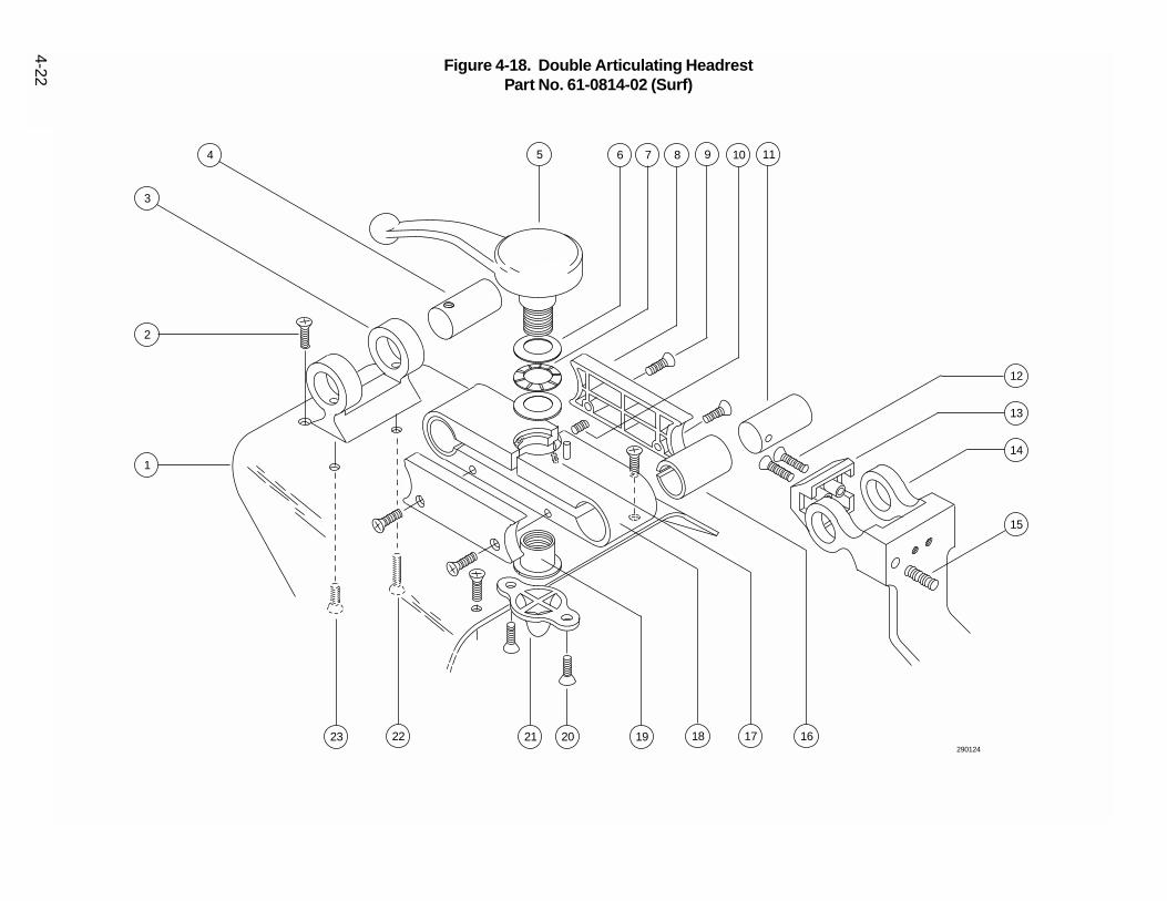
4-22
1920212223
1
2
3
4 5 6 7 8 9 10 11
12
13
14
15
161718
Figure 4-18. Double Articulating Headrest Part No. 61-0814-02 (Surf)
290124

Ref.No. Description Part No. Code
1 Headrest Cover, Dbl Artc Hr, Surf 61-0829-02 52 Screw,Pan Hd Phil,6-32 X 1 1/2,Zinc 005-062-00 13 Headrest Yoke, Surf 61-0817-02 54 Pivot Shaft, Upper, Headrest, Crm. 61-0822-01 55 Handle, Dbl Artic Headrest, Surf 61-1553-00 46 Washer, Thrust, Bearing, .500 ID 004-136-00 57 Bearing, Thrust Needle, .500 ID 016-033-00 58 Side Plate, Headrest Body, Surf 61-0827-02 59 Screw, Fl Hd Phil, 4-40 X 1/2, Nkl 002-114-00 110 Set Screw, Soc Cup Pt, 10-32 X 3/16 007-003-00 111 Pivot Shaft, Lower, Headrest, Crm. 61-0830-01 512 Screw, Fl Hd Soc, 10-32 X 1/2, Zinc 002-089-00 113 Bumper, Headrest Slide Bar, Surf 61-0826-02 314 Slide Bar Dbl Artc Hr, Plate 61-0818-02 515 Set Screw, Cup Pt, 1/4-20 X 1 1/4 007-049-00 116 Bushing, Modified, Headrest 61-0816-00 517 Set Screw, Flat Pt, 6-32 X 3/8 Blk 007-052-00 118 Body, Dbl Articulated Hr, Surf 61-0815-02 519 Locking Nut,Headrest, 1/2-10 Thd 61-1551-00 520 Screw, Fl Hd Phil, 4-40 X 1/4, Nkl 002-113-00 121 Bumper, Headrest Body, Surf 61-0828-02 322 Screw,Fl Hd Phil,6-32 X 3/4, Blk Ox 005-053-00 523 Screw, Fl Hd Soc, 10-32 X 1, Zinc 001-013-00 1
Not ShownUpholstery, Contour Hr, Dbl Artic. 61-0785-00 5Upholstery Contour Hr Dbr Artc Surf 61-0785-01 5
4-23
Table 4-18. Double Articulating Headrest Parts List

4-24 Figure 4-19. Multi-Function Foot SwitchPart No. 61-0969-01 (Gray)
1
2
3
4
5 6 7 8 9 10 11
12
13
14
15
16
17
18
20
19
290125

4-25
Ref.No. Description Part No. Code
1 Strip, Spacer, Foot Switch 61-0804-00 52 Base, Foot Switch 61-0803-00 53 Screw, Pan Hd Phil, 6-32 X 3/8, Zinc 002-015-00 14 Screw, Fl Hd Phil, 6-32 X 3/8, Zinc 001-022-00 1
Replaced by:Screw, Flat Head, Self-Tap, Phil, 6-32 X 3/8 003-097-00 1on S/N A4-0160 and later
5 Bumper, Pad, Rubber, 1/2 Dia, Gray 017-007-00 36 Base Plate, Foot Sw Multi-Fctn Gray 61-0971-01 57 Spacer, Tapered, Foot Switch 61-0335-00 48 Washer, Flat, Fiber, .128 ID 004-010-00 49 Spacer, Plain, Foot Switch 61-0336-00 410 Ball, .250 Dia, Stainless Steel 015-015-00 411 Switch, Miniature, 10A, 125/250 VAC 041-119-00 312 Spring, Elastic, 11/16, Foot Switch 61-0337-00 413 Pin, Dowel, .125 Dia x .50 Long, SS 011-052-00 414 Body, Foot Switch, Cndct, New/Gray 61-0802-01 415 Switch, Push Button, SPST 5A 115 VAC 041-059-00 316 Standoff, Button, Foot Switch 61-0975-00 417 Button, Foot Switch, Red 61-0974-00 318 Housing, Button, Foot Switch, Gray 61-0972-01 519 Button, Foot Switch, Green 61-0974-01 320 Spring Helical Cprsn .720 OD X 1.25 013-067-00 4
Not ShownCable Assy, Foot Sw Multi-Function, Gray 61-0976-01 3
Table 4-16. Multi-Function Foot Switch Parts List

4-26
123
0
Ref.No. Description Part No. Code
1 Label, Footswitch, 8 Function, L.H. 051-163-00 52 Label, Footswitch, 8 Function, R.H. 051-164-00 53 Actuator, Program Footswitch, 8 Function 61-2043-00 54 Actuator Assy, Footswitch 8-Function 61-2042-00 55 Cover Assy, Foot Switch, 8-Function, Surf 6 61-2047-00 56 Membrane Switch, Foot Switch, 8 Function
Service Kit 61-2189-00 57 Base, Footswitch, 8-Function 61-2040-00 58 Bumper, Pad, Rubber, 1/2 Dia, Gray 017-007-00 59 Screw, Pan Hd Phil, 6-32 X 7/8, Zinc 002-032-00 110 Washer, Lock, Int Tooth #6, Zinc Plated 004-073-01 111 Cable Assy, Foot Switch, 8 Function, Surf 6 61-2108-00 5
Table 4-17. 8-Function Foot Switch Parts List
Figure 4-20. 8-Function Foot SwitchPart No. 61-2027-00
1 2
3
4
5
6
7
8
9
10
11

Voltage: 100, 120 VAC or 240 VAC
Amperage: 8.5 Amp (100/120 VAC)(max load) 4.25 Amp (240 VAC)
Est. Weight:1010 270 lbs (136 kg)1015/20 270 lbs (136 kg)
Hydraulic Fluid: 30 oz. (Dry fill.)(Order A-dec P/N 61-0197-00,one 16 oz. bottle.)
Dimensions
A-1
APPENDIX ASPECIFICATIONS
Figure A-1. 1010/15/20 Chair Footprint Dimensions
Figure A-2. 1010 Chair Vertical Dimensions
6"15cm
27"69cm
21"53cm
27"69cm
30°
30°33"
84cm
70"178cm
13"33cm
13.5"34cm
18.75"48cm
15"38cm
15"38cm
13"33cm
59.5"151cm
60°
54"137cm
30"76cm
25"63.5cm
27"69cm
070011
290068

A-2
Figure A-3. 1015/20 Chair Vertical Dimensions
12"30cm11"
28cm
14"36cm
20"51cm
10"25cm
13"33cm
60°
70"178cm
58.5"149cm
53.5"136cm
28"71cm
23"58cm
25"63cm
070009
070010

APPENDIX B
SERVICE NOTES
Eliminating Hydraulic Cylinder Noise
In most cases it will not be necessary to replace thecylinder to solve a noise problem. Order A-dec P/N61-0839-00, an hydraulic oil additive. The additiveeliminates any low-pitched groaning caused by thepiston seal.
In rare cases, the noisy cylinder will emit a high-pitched squeak caused by the cylinder rod wiperbeing dry. The squeak can be eliminated by applyinga light coating of a lubricant, such as A-dec siliconelubricant, (P/N 98-0090-00) to the cylinder rod.
If the cylinder continues to squeak after it's been lubri-cated, or groans even with the additive installed, ordera replacement cylinder.
Improved Headrest Glidebar TensionWedge
Wear in the headrest glidebar tension mechanismmay reduce or eliminate the tension adjustmentrange. Order A-dec P/N 61-1303-00 (a new slidingwedge assembly). The new wedge assembly has aNylatron® wear pad, linear expander spring, and ure-thane back-up pad to provide a greater adjustmentrange and improved holding capability. The newwedge replaces the existing wedge in the headrestglidebar tension mechanism. Installation instructionsare included with the new wedge assembly.
Improving Lumbar Support
If necessary, the position of back lumbar support canbe modified by increasing the height of the toeboardwear pads. A retro-fit wear-pad spacer kit is availablewhich elevates the end of the toeboard by an addi-tional 2-1/2”. Order A-dec P/N F84-712.
All 1010, 1015, and 1020 chairs manufactured afterchair S/N G069170 include the new wear pads.
B-1

Replacing an old-style circuit board:
If you are replacing a circuit board on a chair having aserial number prior to those listed above, order a newPCB and a PCB conversion kit (A-dec Kit No. L37-365). The in-line fuse (120V chairs only) can be left inthe solenoid wiring harness when replacing an old-style circuit board.
Replacing a cover or store button extensionassembly:
The old-style cover (A-dec P/N 61-1386-00) assemblyand store button extension assembly (A-dec P/N 61-1389-00) are available for field replacement shouldthey become lost or damaged.
Replacing all four solenoids:
If you are replacing all four (4) solenoids on a 120Vchair, specify that the solenoid set is for a 120V chairto ensure a solenoid fuse is included in the wiring har-ness. This applies only to a 120V chairs prior to S/NJ078003.
Replacing only one solenoid:
When replacing only one solenoid, order the appropri-ate kit listed below:
Voltage P/N
100V L37-386120V L37-387240V L37-388
Yellowing 1015 Chair Armrests
Surf-colored 1015 chair armrests have, in the past,shown a tendency to yellow when exposed to ultravio-let light and certain alcohol-based disinfectants. Toeliminate the problem, A-dec has been molding thearmrests with a protective barrier-coated materialsince mid-January, 1990.
The barrier coating first used on the armrests shippedbetween mid-January, 1990 and mid-May, 1990 pro-tected well against UV rays, but did not resist alcohol-based chemical disinfectants. As a result, this barriercoating was being wiped off with certain alcohol-based disinfectants. The currently used coating givesexcellent UV stability as well as offering superiorresistance to disinfectants. To replace yellowed arm-rests, order A-dec P/N 61-1404-00.
Improved Clamping on DoubleArticulating Headrest
The headrest locking capability has been improved bychanging the handle and nut insert from 1/2-13threads to 1/2-10 threads. The improved clamping willallow the headrest to carry a higher load. As a resultof these changes, the handle will be slightly harder toturn (requires about 20% more effort). The new han-dles do not look any different.
When a new handle, A-dec P/N 61-1553-00,(replaces A-dec P/N 61-0825-00) is ordered, the mat-ing locking nut (A-dec P/N 61-1551-00) will be includ-ed.
B-2
Replacing a Printed Circuit Board
Due to changes to the 1010/15 printed circuit board (PCB), there are new part numbers for the PCB, PCB cover,and the PCB store button extension assembly. The most noticeable change to the PCB is that a new PCB hasone or two fuse holders mounted perpendicular to the board, the older PCB has a single fuse holder mountedflat on the board. These new parts are shipped as a kit, they are not interchangeable with the older parts. Theold and new part numbers and the chair serial numbers that the change took place on are as follows:
Description Old P/N New P/N S/N Changeover
Circuit Board Assembly, 100V 61-1373-00 61-1373-01 A1XXXXXCircuit Board Assembly, 120V 61-1214-00 61-1214-01 J078003Circuit Board Assembly, 240V 61-1217-00 61-1217-01 H073332PCB Cover Assembly 61-1386-00 61-1515-00* B193179Store Button Extension Assembly 61-1389-00 61-1530-00*
* Included with the appropriate PCB.

Eliminating Hydraulic System "Buzz"
Beginning in June,1990, 1010/15/20 chairs include alarger-diameter pickup tube in the hydraulic fluidreservoir. A larger pickup tube increases the flow ofhydraulic fluid to the pump and eliminates the tenden-cy of the hydraulic system, when the fluid is cold, toemit a momentary “buzzing” noise (caused by thehydraulic pump cavitating).
If a chair emits a momentary buzzing noise whencold, check for the type of reservoir tank (locatedunder the motor/pump cover). If the tank is plastic,and the chair was shipped prior to June 1990 (checkthe serial number tag), replace the old pickup tubewith a new pickup tube (A-dec P/N 61-1489-00). If thechair has a metal reservoir tank, install a new plasticreservoir tank (A-dec P/N 61-1339-00) and new pick-up tube assembly (A-dec P/N 61-1488-00).
Improved Headrest Knob
A number of early 1010/15 chairs were shipped with-out lubricant on the threads of the headrest knob,resulting in the knob being difficult to tighten. If youhave a headrest that is difficult to tighten, remove theknob from the headrest and lubricate the threads witha small amount of synthetic grease such as A-decSilicone Lubricant.
Additionally, the shape of the headrest knob has beenchanged to a scalloped design which provides theoperator with a better grip. The new knob began ship-ping with chair S/N J077784 in early October of 1990.The knob will retro-fit to all earlier 1010/15 headrests.To replace a smooth knob with a scalloped knob,order A-dec P/N 61-1232-00.
When installing the new knob, remember to lubricatethe threads with a small amount of synthetic grease.
1015 Vac Back Umbilical Changes
A PVC sleeve is being used to cover 1015 Vac Backchair umbilical tubing in place of the braided sleevingpreviously used. The PVC sleeve is water-tight foreasier cleaning, and surf-colored to improve appear-ance. To replace an umbilical with braided sleeving,order A-dec part numbers:
61-1550-00 Umbilical Assembly40-0145-00 Adapter, Tubing 5/8 to 1/2024-037-00 Tubing, Convolute, Gray 5/8 ID
To install a new umbilical on a 1015 Vac Back chair,complete the following instructions:
1. At the connection to the manifold on the chair back,install a short length of convolute tubing and anadapter tube. Use 3M® plastic adhesive #4693, orequivalent, to seal the parts in place.
2. Connect the end of the new umbilical vacuum tub-ing to the adapter tube. Use 3M plastic adhesive#4693, or equivalent, to seal the parts in place.
3. At the connection to the canister, remove the oldconvolute vacuum tubing and install the new umbil-ical vacuum tubing to the canister.
4. Connect the syringe tubing. Be sure to connectribbed tubing to ribbed tubing.
In addition, the vacuum tube inside the umbilical hasbeen reduced from 5/8 ID to 1/2 ID to standardize VacBack tubing between the 1005 and 1015 chairs.
B-3
CAUTIONDO NOT USE PETROLEUM-BASED LUBRICANT(such as Lubriplate, Vaseline, 3-in-1 Oil,Handpiece Lubricant, etc.) ON THE HEADRESTKNOB.
Installing a Second Footswitch
To add a second footswitch to a 1010/15/20 chair,order A-dec Part No. 61-1029-00. The kit includes astandard gray multi-function footswitch, the requiredadapter cable, hardware, and instructions needed forthe installation.
New Store Button Actuator
Previously the store button has been actuated byinserting a probe through a hole in the motor/pumpcover. Effective with chair S/N L086602, a rubber but-ton is included in the motor/pump cover eliminatingthe need for a probe.
Mechanical Stop Added to Chair Back
A stop bracket has been added to the chair back limitswitch assembly to eliminate the following problem:
The chair back may be physically forced forward dam-aging the limit switch assembly. Although it is unlikelythis would happen to an installed chair, however, dam-age to the switch assembly may occur during ship-ment or installation. To replace a damaged limit switchassembly, order A-dec Kit No. L37-389. The kitincludes a new limit switch, mounting bracket, the stopbracket and instructions. All 1010 and 1015 chairs,serial number C194177 through C197582 include thestop bracket. All 1010 and 1015 chairs manufacturedafter C197582 have the stop incorporated into thechair upper structure casting.
Controller Software Change
A software change to the chair controller was made inNovember, 1990 to eliminate the following problem:
When Back Up switch was pressed, then Base Upswitch was pressed, then Back Up released, etc., inrapid succession, and, if the back was close to the up-limit of travel, the back may travel past the limit switchdamaging the Back Up limit switch, limit switch brack-et, or potentiometer assembly. This was caused byhydraulic pressure in the lift cylinder preventing theBack Up manifold valve from closing for several sec-onds.
The new controller software shuts the motor offmomentarily when Back Up is released, allowinghydraulic pressure in the system to drop and the man-ifold valve to close. While there was some potential forminor damage to a chair (not every chair has thisproblem), note that there is no hazard of injury to thepatient or to the operator due to this problem.
Improved Chair Headrest Positioning
Effective August 1, 1991 the headrest pivot positionon the 1010 and 1015 chair glidebar (P/N 61-1509-00) has been modified to increase the angle that theheadrest can be tipped back. This modification will setthe cushion approximately 3/8" back from its previousposition. Additionally, the modification allows theheadrest to be positioned approximately 1/8" lowerthan was previously possible.
B-4

IC Cuspidor Safety Switch
Effective July 28, 1991, the cuspidor safety switch fora 1010/15 mounted IC Cuspidor is standard. Thefunction of the safety switch is to shut off the chair ifthe cuspidor is lowered onto an object.
For ease of installation, the cuspidor end of the safetyswitch cable plugs into a connector labeled CUSP onPCBs shipped after the above date. For 1010/15chairs having an older PCB without the cuspidor con-nector, an adapter cable is shipped with each cuspi-dor. Complete instructions are included with the kit.
Thicker Upholstery
Effective November 1, 1991, a thicker set of uphol-stery with added lumbar support will be standard for1010/15/20 chairs. The original upholstery was madeusing 2" thick foam, the new upholstery is made fromfoam 2 3/4" thick.
The new upholstery set provides a softer cushion.
New Upholstery Material
A-dec has begun using two lines of vinyl upholsterymaterial from a new supplier.
One line “Duration” replaces the Naugahyde“Neochrome” and has the added advantage of anantimicrobial ingredient. The other new line“Hampton” replaces the Naugahyde “Caressa.”
Color choices have changed slightly, contact your A-dec authorized dealer for more information.
1010/15/20 Vac Back
As the backrest of the 1010/15/20 Vac Back Chairmoves from upright to supine, the assistant's instru-ment holder does not remain perfectly horizontal (6°variation maximum). With the back up, the holder barwill be horizontal. As the back is lowered, the bar will“tilt” a bit, then as the back goes further down, theholder will return to a nearly horizontal position.
The interim “tilt” is minimal and may not be noticed bymost users and does not effect the performance of theVac Back unit. However, if the holder bar is not hori-zontal when the chair back is placed in the preferredoperating position, an adjustment can be made.
Place the chair in the preferred operating position,then raise or lower the instrument holder bar until it isin the desired position. A slip joint at the base of theholder bar arm allows this adjustment although it willtake a little effort to overcome the resistance in thejoint.
Once the new position has been established, the armwill always be horizontal when the chair back is in thepreferred operating position.
B-5

AdjustmentsAdjustment Procedures ................................ 2-5,6, 3-1Base Up Limit Switch ............................................ 3-25Auto Positioning .................................................... 3-28Base and Back Rate of Travel .............................. 3-24Double Articulating Headrest Pivot Tension ......... 3-29Headrest Glidebar Tension ................................... 3-29Back Positioning Potentiometer ........................... 3-27Base Positioning Potentiometer ........................... 3-26Base Up Limit Switch ............................................ 3-25Programming the Chair ................................. 2-2, 3-28Rate of Travel .......................................................... 2-2
FaultsTroubleshooting Procedures ............................... 3-1,2Auto-Positioning Function Inoperative ................. 3-14Back Moves for Base Only Function .................... 3-15Base Moves for Back Only Function .................... 3-15Base or Back Down Function is Inoperative ........... 3-8Base or Back Up Function is Inoperative ................ 3-5Chair is Inoperative ................................................. 3-3Incomplete Auto-Positioning Cycle ....................... 3-11Unable to Program Auto Positioning ...................... 3-9
ProceduresDepressurizing the Hydraulic System .................. 3-24Eliminating Hydraulic Cylinder Noise ..................... B-1Eliminating Hydraulic System Buzz ....................... B-3Installing a Second Footswitch ............................... B-4Navigating the Flow Charts ..................................... 3-2Remove and Replace a Solenoid ........................... 3-1Replace a Damaged Limit Switch .......................... B-4Replace Yellowed Armrests ................................... B-2Replacing a Pump Cover or Store Button .............. B-2Replacing a Printed Circuit Board .......................... B-2Replacing All Four Solenoids ................................. B-2
TestsTesting Procedures ............................................. 2-5-6Chair Test Points .................................................. 3-17Continuity and Voltage .......................................... 3-18Limit Switch Continuity .......................................... 3-18Power Cord Continuity .......................................... 3-18Pump Motor .......................................................... 3-22Relay Click Test .................................................... 3-17Solenoid Continuity ............................................... 3-21Solenoids for Magnetic Pull .................................. 3-22Switch Voltage ...................................................... 3-20Wiring Harness Continuity Test ............................ 3-19
Back Tilt ................................................... 2-2,5,7, 4-8, B-5Base Lift Manifold ......................................................... 4-8Baseplate ............................................................... 2-1,2,6Brake Lever ................................................................ 4-18Chair Dimensions ..................................................... A-1,2Chair Back ........................................ 2-1,5, 4-15,16, B-3,5Circuit Board Assembly ........................................ 4-7, B-2Controller Software Change ........................................ B-4Dental Chair Assemblies .............................................. 2-1Double Articulating Headrest ................. 3-1, 4-22,23, B-2Electrical Schematic, 100V ..................................... 2-8,11Electrical Schematic, 120V ..................................... 2-9,12Electrical Schematic, 240V ................................... 2-10,13Electro-Hydraulic System .................... 2-2, 3-17,21, 4-6,8Electronic Control ......................................................... 2-2Filter Screens ............................................................... 4-8Footswitch ........................................... 2-2,5, 4-24,25, B-4Fuse Holders ................................................................ B-2Fuses ............................................................................ 4-7Hydraulic Fluid ........................................................... 4.1-7Hydraulic Lock ................................................... 3-3,5,8,24Hydraulic Schematic .................................................. 2-14Hydraulic System .................................... 2-1,2,7, 3-1, B-3Hydraulic Cylinders ........................................ 2-2, B-1,3,4Hydraulic Fluid Reservoir ........................... 2-2, 4-6,7, B-3Hydraulic Oil Additive ................................................... B-1Hydraulic Pump .................................... 2-2,6,7, 4-6,7, B-3IC Cuspidor Safety Switch ........................................... B-5Illustrated Parts Breakdown ......................................... 4-1Chair Headrest Positioning .......................................... B-4Headrest Glidebar Tension Wedge ............................. B-1Headrest Knob ............................................................. B-3Lumbar Support ........................................................... B-1Limit Switches ............. 2-2,5,6, 3-2,18,19,20,25, 4-3,5,13Lubriplate ..................................................................... B-3Manifold Assembly ................................................. 2-2,5,7Mechanical Stop Added to Chair Back ........................ B-4Month and Year Manufactured .................................... 1-2Multi-Function Footswitch ......................................... 2-1,5New Upholstery Material ............................................. B-5PCB connector P6 ........................................................ 3-2PCB Cover Assembly .................................................. B-2PCB .................................................... 2-5,8,13, 3-2, B-2,5Positioning Potentiometers ............................ 2-5, 3-26,27Power Supply ............................................................... 2-5Pre-Position .................................................................. 2-2Relays ........................................................ 2-1, 2, 5, 6, 3-2Serial Number ............................................. 1-2, 15, B-2, 4Service Information ...................................................... 2-1Service Notes ............................................................... B-1Service and Support ................................................... 2-15Service Parts Codes ............................................. 1-1, 4-1
(continued)
I-1
GENERAL INDEX

Softer Cushion ............................................................. B-5Solenoid Wiring Harness ............................................. B-2Solenoid/Manifold Assembly ............ 2-1,2,5-7, 4-8,9, B-2Specifications ............................................................... A-1Standard Articulating Headrest .................................. 4-21Starter Capacitor ................................................ 2-2, 4-6,7Store Button Extension Assembly ............................... B-2Surf-Colored 1015 Chair Armrests .............................. B-2Swivel Brake ......................................................... 4-18,19Systems Description .................................................... 2-2Test Points ................................................................ 2-2, 5Thicker Upholstery ....................................................... B-5Toeboard Assemblies .......................... 1-2, 2-1, 4-20, B-1Vac Back Umbilical Changes ...................................... B-3Vac Back .................................................... 4-15,17, B-3,5Vinyl Upholstery ........................................................... B-5Year and Model Variations ........................................... 1-2
001-002-00 ................................................................ 4-9001-013-00 .............................................................. 4-23001-016-00 .............................................................. 4-15001-021-00 ................................................................ 4-3001-022-00 .............................................................. 4-25001-161-00 .............................................................. 4-14001-177-00 .............................................................. 4-19002-015-00 .............................................................. 4-25002-024-00 ........................................................... 4-5,13002-039-00 .............................................................. 4-19002-050-00 .............................................................. 4-12002-073-00 .............................................................. 4-21002-080-00 ......................................................... 4-12,15002-085-01 .............................................................. 4-11002-089-00 .............................................................. 4-23002-101-00 ................................................................ 4-9002-113-00 .............................................................. 4-23002-114-00 .............................................................. 4-23004-010-00 .............................................................. 4-25004-012-00 ................................................................ 4-9004-015-00 .............................................................. 4-21004-136-00 ......................................................... 4-21,23004-139-00 .............................................................. 4-17004-140-00 .............................................................. 4-17004-161-00 ................................................................ 4-7004-165-00 .............................................................. 4-19005-002-01 ........................................................ 4-2,4,11005-007-01 .............................................................. 4-11005-008-00 ................................................... 4-3,5,12,13005-012-02 .............................................................. 4-20005-053-00 .............................................................. 4-23005-062-00 .............................................................. 4-23005-109-00 .............................................................. 4-17005-109-01 ........................................................... 4-3,17005-110-00 ...................................................... 4-7,14,21005-112-00 ........................................................ 4-2,4,19005-124-00 ......................................................... 4-11,17006-002-00 .............................................................. 4-14006-016-00 ................................................................ 4-7006-023-00 .............................................................. 4-12006-112-00 ................................................................ 4-7007-003-00 .............................................................. 4-23007-004-00 ................................................................ 4-5007-010-00 ................................................................ 4-5007-043-00 .............................................................. 4-17007-047-00 .............................................................. 4-17007-049-00 .............................................................. 4-23007-052-00 .............................................................. 4-23010-031-00 .............................................................. 4-15010-050-00 .............................................................. 4-20010-051-00 .............................................................. 4-12010-053-00 .............................................................. 4-15011-035-00 .............................................................. 4-13011-052-00 .............................................................. 4-25
I-2
GENERAL INDEX PART NUMBER INDEX

011-087-00 .............................................................. 4-20011-091-00 .............................................................. 4-19011-092-00 .............................................................. 4-19012-011-00 ................................................................ 4-2013-044-00 ................................................................ 4-9013-054-00 .............................................................. 4-12013-067-00 .............................................................. 4-25015-015-00 .............................................................. 4-25016-033-00 ......................................................... 4-21,23016-053-00 .............................................................. 4-17016-054-00 .............................................................. 4-17017-007-00 .............................................................. 4-25018-010-01 .............................................................. 4-11018-040-00 .............................................................. 4-17022-025-00 ................................................................ 4-9022-049-00 ................................................................ 4-9025-058-00 ................................................................ 4-7030-004-00 ................................................................ 4-9030-010-00 ................................................................ 4-9030-012-00 .............................................................. 4-21030-016-00 ................................................................ 4-9036-031-00 .............................................................. 4-13036-035-00 ................................................................ 4-7037-018-00 .............................................................. 4-21041-059-00 .............................................................. 4-25041-119-00 .............................................................. 4-25041-164-00 ................................................................ 4-7041-165-00 ................................................................ 4-7041-360-00 ................................................................ 4-7041-372-00 ........................................................... 4-5,13044-049-00 .............................................................. 4-12044-049-01 ........................................................ 4-3,5,13046-069-00 ................................................................ 4-7055-122-00 ................................................................ 4-960-0080-00 ................................................................ 4-561-0109-02 ................................................................ 4-761-0109-03 ................................................................ 4-761-0217-03 ........................................................... 4-7,1261-0335-00 .............................................................. 4-2561-0336-00 .............................................................. 4-2561-0337-00 .............................................................. 4-2561-0460-00 ................................................................ 4-961-0461-00 ................................................................ 4-961-0464-00 ................................................................ 4-961-0465-00 ................................................................ 4-961-0785-00 .............................................................. 4-2361-0785-01 .............................................................. 4-2361-0802-01 .............................................................. 4-2561-0803-00 .............................................................. 4-2561-0804-00 .............................................................. 4-2561-0815-02 .............................................................. 4-2361-0816-00 .............................................................. 4-2361-0817-02 .............................................................. 4-2361-0818-02 .............................................................. 4-23
61-0822-01 .............................................................. 4-2361-0826-02 .............................................................. 4-2361-0827-02 .............................................................. 4-2361-0828-02 .............................................................. 4-2361-0829-02 .............................................................. 4-2361-0830-01 .............................................................. 4-2361-0925-01 .............................................................. 4-1761-0953-01 .............................................................. 4-1761-0969-01 .............................................................. 4-2461-0971-01 .............................................................. 4-2561-0972-01 .............................................................. 4-2561-0974-00 .............................................................. 4-2561-0974-01 .............................................................. 4-2561-0975-00 .............................................................. 4-2561-0976-01 .............................................................. 4-2561-0991-00 .............................................................. 4-1561-1022-00 .............................................................. 4-1561-1202-00 .............................................................. 4-1161-1204-00 ............................................................. 4-2,461-1205-00 ................................................................ 4-461-1206-00 ................................................................ 4-461-1208-00 .............................................................. 4-2061-1210-00 .............................................................. 4-2061-1214-01 ................................................................ 4-761-1217-01 ................................................................ 4-761-1220-00 ................................................................ 4-761-1222-00 ................................................................ 4-561-1223-00 ................................................................ 4-561-1224-00 ......................................................... 4-12,1361-1225-00 .............................................................. 4-1361-1226-00 .............................................................. 4-1361-1227-00 .............................................................. 4-2161-1228-00 .............................................................. 4-2161-1232-00 .............................................................. 4-2161-1237-00 .............................................................. 4-2161-1253-00 .............................................................. 4-1161-1255-00 .............................................................. 4-1161-1257-00 .............................................................. 4-2061-1267-00 ......................................................... 4-10,1261-1275-00 ............................................................. 4-3,461-1287-00 .............................................................. 4-1061-1295-00 ................................................................ 4-561-1314-00 .............................................................. 4-1261-1315-00 .............................................................. 4-1361-1326-00 ................................................................ 4-761-1327-00 ................................................................ 4-761-1328-00 ................................................................ 4-761-1332-00 ................................................................ 4-761-1333-00 ................................................................ 4-761-1334-00 ................................................................ 4-761-1335-00 ................................................................ 4-961-1336-00 ................................................................ 4-961-1337-00 ................................................................ 4-961-1338-00 ................................................................ 4-7
I-3
PART NUMBER INDEX

61-1339-00 ................................................................ 4-761-1346-00 .............................................................. 4-1961-1351-00 .............................................................. 4-1161-1366-00 ................................................................ 4-761-1367-00 ................................................................ 4-561-1373-01 ................................................................ 4-761-1384-00 ................................................................ 4-761-1395-00 ................................................................ 4-261-1396-00 ................................................................ 4-261-1397-00 ................................................................ 4-261-1398-00 ................................................................ 4-261-1399-00 ................................................................ 4-261-1400-00 ................................................................ 4-261-1401-00 ................................................................ 4-261-1404-00 .............................................................. 4-1161-1411-00 ................................................................ 4-361-1412-00 ............................................................. 4-3,761-1413-00 ................................................................ 4-361-1414-00 .............................................................. 4-2061-1418-00 .............................................................. 4-2061-1438-00 .............................................................. 4-1161-1441-00 ................................................................ 4-261-1448-00 .............................................................. 4-1561-1483-00 .............................................................. 4-1961-1488-00 ................................................................ 4-761-1502-00 ................................................................ 4-561-1503-00 ................................................................ 4-761-1509-00 .............................................................. 4-2161-1512-00 .............................................................. 4-2161-1513-00 .............................................................. 4-2161-1525-00 .............................................................. 4-1961-1532-00 .............................................................. 4-1761-1533-00 .............................................................. 4-1761-1535-00 .............................................................. 4-1761-1536-00 .............................................................. 4-1961-1537-00 .............................................................. 4-1961-1538-00 .............................................................. 4-1961-1540-00 .............................................................. 4-1961-1541-00 .............................................................. 4-1961-1542-00 .............................................................. 4-1961-1551-00 .............................................................. 4-2361-1553-00 .............................................................. 4-2361-1568-00 .............................................................. 4-1461-1569-00 .............................................................. 4-1461-1570-00 .............................................................. 4-1461-1571-00 .............................................................. 4-1461-1572-00 .............................................................. 4-1461-1607-00 .............................................................. 4-20F84-705 ................................................................... 4-12F84-706 ................................................................... 4-12L37-385 ................................................................... 4-13
I-4
PART NUMBER INDEX

POST OFFICE BOX 111NEWBERG, OREGON 97132-0111 U.S.A.
TELEPHONE 1-800-547-1883(503) 538-7478TELEX 4970448
FAX (503) 538-5911
R
PUB. NO. 85-0808-0010/94
Printed in U.S.A.Copyright © 1994All Rights Reserved