Embed Size (px)
Citation preview
A-dec 300 Delivery SystemsModels 332, 333, 334, 335, and 336
Instructions for Use
A-dec 300 Delivery Systems Instructions for Use
Copyright© 2017 A-dec Inc. All rights reserved.
A-dec Inc. makes no warranty of any kind with regard to this material, including, but not limited to, the implied warranties of merchantability and fitness for a particular purpose. A-dec Inc. shall not be held liable for any errors contained herein or any consequential or other damages concerning the furnishing, performance or use of this material. The information in this document is subject to change without notice. If you find any problems in the documentation, please report them to us in writing. A-dec Inc. does not warrant that this document is error-free.
No part of this document may be copied, reproduced, altered, or transmitted in any form or by any means, electronic or mechanical, including photocopying, recording, or by any information storage and retrieval system, without prior written permission from A-dec Inc.
Trademarks and Additional Intellectual Property RightsA-dec, the A-dec logo, A-dec Inspire, Cascade, Century Plus, Continental, Decade, ICX, ICV, Performer, Preference, Preference Collection, Preference ICC, Radius, and reliablecreativesolutions are trademarks of A-dec Inc. and are registered in the United States and other countries. A-dec 500, A-dec 400, A-dec 300, A-dec 200, and EasyFlex are also trademarks of A-dec Inc. None of the trademarks or trade names in this document may be reproduced, copied, or manipulated in any manner without the express, written approval of the trademark owner.
Certain touchpad symbols are proprietary to A-dec Inc. Any use of these symbols, in whole or in part, without the express written consent of A-dec Inc., is strictly prohibited.
Regulatory InformationRegulatory information mandated by agency requirements is provided in the Regulatory Information, Specifications, and Warranty document (p/n 86.0221.00), which is available in the Document Library at www.a-dec.com.
Product ServiceProduct service is available through your local authorized A-dec dealer. For service information, or to locate an authorized dealer, contact A-dec at 1.800.547.1883 in the USA and Canada or 1.503.538.7478 worldwide, or visit www.a-dec.com.
Product Models and Versions Covered in This Document
Model Versions Description
332 A Delivery System
333 A Delivery System
334 A, B Delivery System
335 A, B Delivery System
336 A Delivery System
86.0092.00 Rev G 1
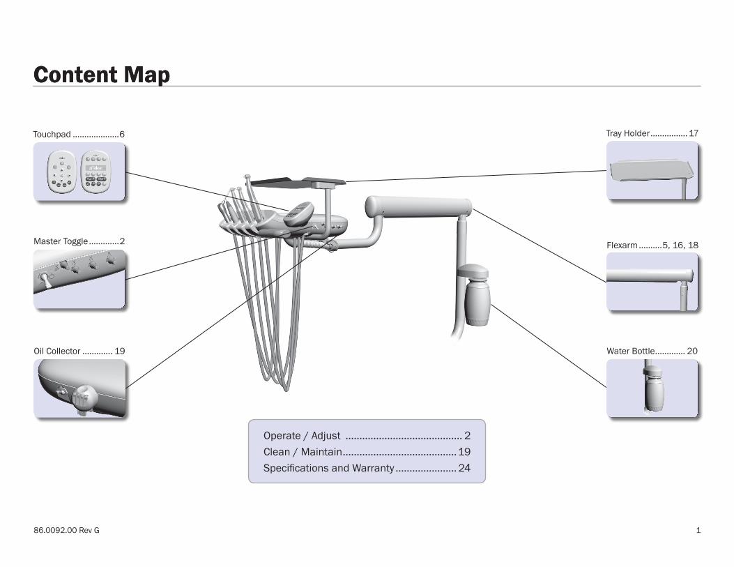
Content MapContent Map
Flexarm ..........5, 16, 18Master Toggle .............2
Tray Holder ................17
Oil Collector ............. 19 Water Bottle ............. 20
Operate / Adjust .......................................... 2Clean / Maintain .........................................19Specifications and Warranty ...................... 24
Touchpad ....................6
2
A-dec 300 Delivery Systems Instructions for Use Operate / Adjust
Operate / Adjust
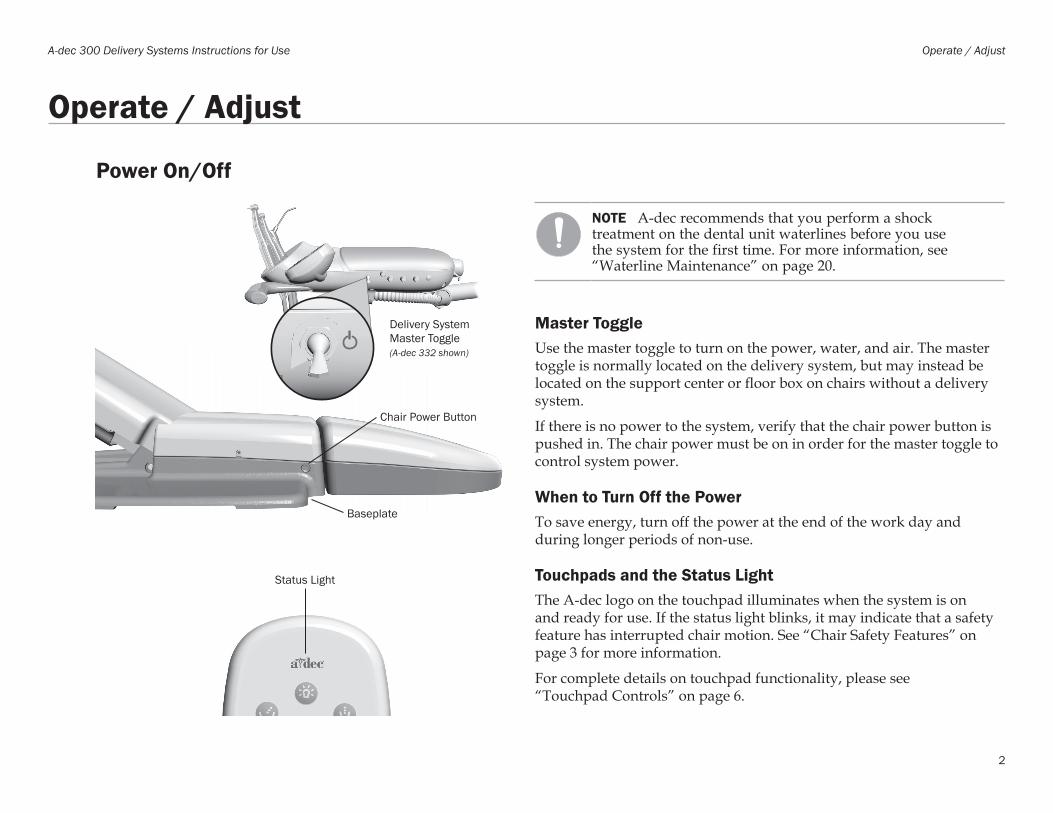
Power On/Off
NOTE A-dec recommends that you perform a shock treatment on the dental unit waterlines before you use the system for the first time. For more information, see “Waterline Maintenance” on page 20.
Master ToggleUse the master toggle to turn on the power, water, and air. The master toggle is normally located on the delivery system, but may instead be located on the support center or floor box on chairs without a delivery system.
If there is no power to the system, verify that the chair power button is pushed in. The chair power must be on in order for the master toggle to control system power.
When to Turn Off the PowerTo save energy, turn off the power at the end of the work day and during longer periods of non-use.
Touchpads and the Status LightThe A-dec logo on the touchpad illuminates when the system is on and ready for use. If the status light blinks, it may indicate that a safety feature has interrupted chair motion. See “Chair Safety Features” on page 3 for more information.
For complete details on touchpad functionality, please see “Touchpad Controls” on page 6.
Status Light
Chair Power Button
Baseplate
Delivery System Master Toggle(A-dec 332 shown)
86.0092.00 Rev G 3
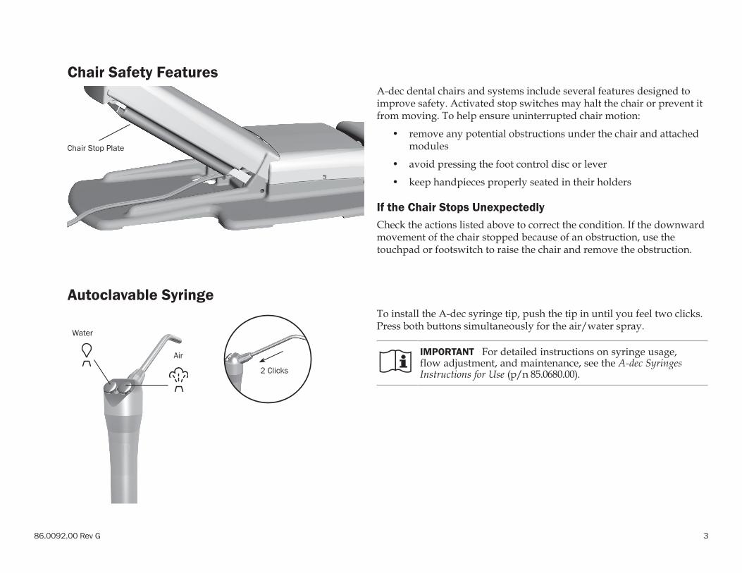
Chair Safety FeaturesA-dec dental chairs and systems include several features designed to improve safety. Activated stop switches may halt the chair or prevent it from moving. To help ensure uninterrupted chair motion:
• remove any potential obstructions under the chair and attached modules
• avoid pressing the foot control disc or lever
• keep handpieces properly seated in their holders
If the Chair Stops UnexpectedlyCheck the actions listed above to correct the condition. If the downward movement of the chair stopped because of an obstruction, use the touchpad or footswitch to raise the chair and remove the obstruction.
Autoclavable SyringeTo install the A-dec syringe tip, push the tip in until you feel two clicks. Press both buttons simultaneously for the air/water spray.
IMPORTANT For detailed instructions on syringe usage, flow adjustment, and maintenance, see the A-dec Syringes Instructions for Use (p/n 85.0680.00).
Chair Stop Plate
Water
Air
2 Clicks
4
A-dec 300 Delivery Systems Instructions for Use Operate / Adjust
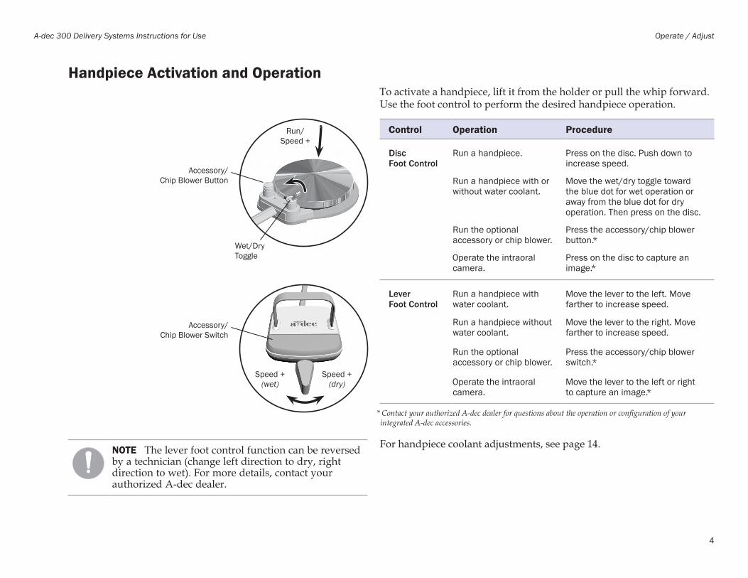
Handpiece Activation and OperationTo activate a handpiece, lift it from the holder or pull the whip forward. Use the foot control to perform the desired handpiece operation.
Control Operation Procedure
Disc Foot Control
Run a handpiece. Press on the disc. Push down to increase speed.
Run a handpiece with or without water coolant.
Move the wet/dry toggle toward the blue dot for wet operation or away from the blue dot for dry operation. Then press on the disc.
Run the optional accessory or chip blower.
Press the accessory/chip blower button.*
Operate the intraoral camera.
Press on the disc to capture an image.*
Lever Foot Control
Run a handpiece with water coolant.
Move the lever to the left. Move farther to increase speed.
Run a handpiece without water coolant.
Move the lever to the right. Move farther to increase speed.
Run the optional accessory or chip blower.
Press the accessory/chip blower switch.*
Operate the intraoral camera.
Move the lever to the left or right to capture an image.*
* Contact your authorized A-dec dealer for questions about the operation or configuration of your integrated A-dec accessories.
For handpiece coolant adjustments, see page 14.
Accessory/Chip Blower Switch
Speed + (dry)
Speed + (wet)
Wet/Dry Toggle
Run/Speed +
Accessory/Chip Blower Button
NOTE The lever foot control function can be reversed by a technician (change left direction to dry, right direction to wet). For more details, contact your authorized A-dec dealer.
86.0092.00 Rev G 5
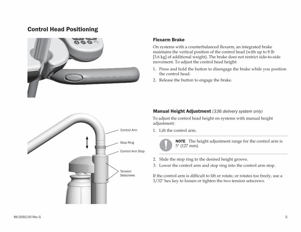
Control Head Positioning Flexarm BrakeOn systems with a counterbalanced flexarm, an integrated brake maintains the vertical position of the control head (with up to 8 lb [3.6 kg] of additional weight). The brake does not restrict side-to-side movement. To adjust the control head height:
1. Press and hold the button to disengage the brake while you position the control head.
2. Release the button to engage the brake.
Manual Height Adjustment (336 delivery system only)To adjust the control head height on systems with manual height adjustment:
1. Lift the control arm.
NOTE The height adjustment range for the control arm is 5" (127 mm).
2. Slide the stop ring to the desired height groove.3. Lower the control arm and stop ring into the control arm stop.
If the control arm is difficult to lift or rotate, or rotates too freely, use a 3/32" hex key to loosen or tighten the two tension setscrews.
Stop Ring
Tension Setscrews
Control Arm
Control Arm Stop

6
A-dec 300 Delivery Systems Instructions for Use Operate / Adjust
Touchpad ControlsThe A-dec touchpad and footswitch control chair movement in the same way. See your dental chair Instructions for Use for detailed information about your footswitch controls.
Basic Touchpad FunctionsYour A-dec 300 system may include a standard or deluxe touchpad, or both. The standard touchpad operates the chair, cuspidor, and dental light functions. The deluxe touchpad adds functions for electric motors and other integrated clinical devices. Both touchpads provide manual and programmable controls.
Cupfill
Deluxe Touchpad
Endodontics/Electric Motor Controls
Dental LightBowl Rinse
Cupfill
Standard Touchpad
Bowl Rinse
Dental Light
Programmable Chair Controls
Manual Chair Controls
86.0092.00 Rev G 7
Touchpad Controls (continued)
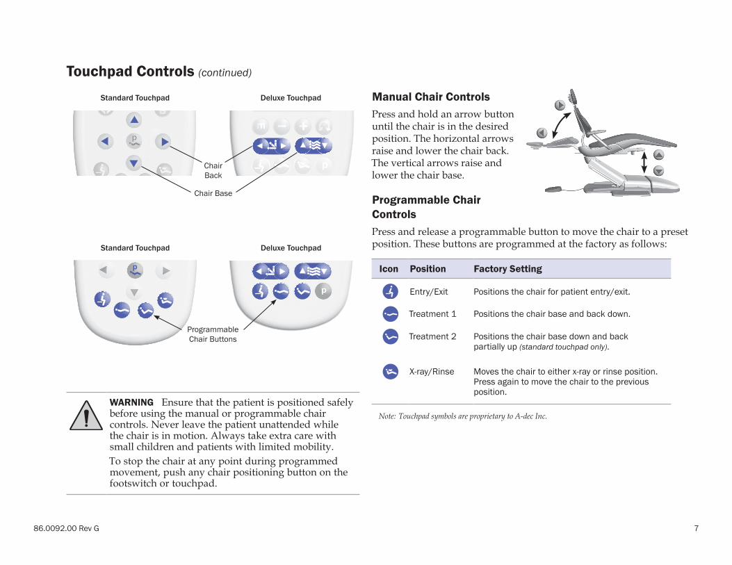
Manual Chair ControlsPress and hold an arrow button until the chair is in the desired position. The horizontal arrows raise and lower the chair back. The vertical arrows raise and lower the chair base.
Programmable Chair ControlsPress and release a programmable button to move the chair to a preset position. These buttons are programmed at the factory as follows:
Icon Position Factory Setting
Entry/Exit Positions the chair for patient entry/exit.
Treatment 1 Positions the chair base and back down.
Treatment 2 Positions the chair base down and back partially up (standard touchpad only).
X-ray/Rinse Moves the chair to either x-ray or rinse position. Press again to move the chair to the previous position.
Note: Touchpad symbols are proprietary to A-dec Inc.
Standard Touchpad Deluxe Touchpad
Chair Back
Chair Base
Standard Touchpad Deluxe Touchpad
Programmable Chair Buttons
WARNING Ensure that the patient is positioned safely before using the manual or programmable chair controls. Never leave the patient unattended while the chair is in motion. Always take extra care with small children and patients with limited mobility.To stop the chair at any point during programmed movement, push any chair positioning button on the footswitch or touchpad.
8
A-dec 300 Delivery Systems Instructions for Use Operate / Adjust
Touchpad Controls (continued)
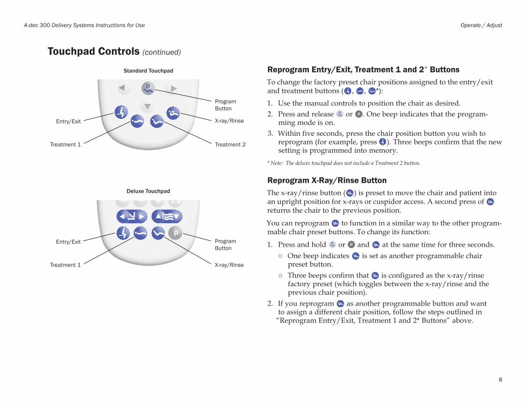
Reprogram Entry/Exit, Treatment 1 and 2* ButtonsTo change the factory preset chair positions assigned to the entry/exit and treatment buttons ( , , *):
1. Use the manual controls to position the chair as desired.2. Press and release or . One beep indicates that the program-
ming mode is on.3. Within five seconds, press the chair position button you wish to
reprogram (for example, press ). Three beeps confirm that the new setting is programmed into memory.
* Note: The deluxe touchpad does not include a Treatment 2 button.
Reprogram X-Ray/Rinse ButtonThe x-ray/rinse button ( ) is preset to move the chair and patient into an upright position for x-rays or cuspidor access. A second press of returns the chair to the previous position.
You can reprogram to function in a similar way to the other program-mable chair preset buttons. To change its function:
1. Press and hold or and at the same time for three seconds.○ One beep indicates is set as another programmable chair
preset button.○ Three beeps confirm that is configured as the x-ray/rinse
factory preset (which toggles between the x-ray/rinse and the previous chair position).
2. If you reprogram as another programmable button and want to assign a different chair position, follow the steps outlined in
“Reprogram Entry/Exit, Treatment 1 and 2* Buttons” above.
Standard Touchpad
Entry/Exit X-ray/Rinse
Program Button
Treatment 2Treatment 1
Deluxe Touchpad
Entry/Exit Program Button
X-ray/RinseTreatment 1
86.0092.00 Rev G 9
Touchpad Controls (continued)
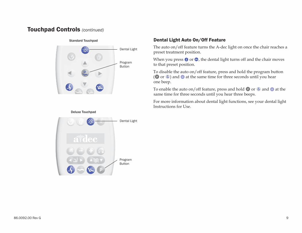
Dental Light Auto On/Off Feature The auto on/off feature turns the A-dec light on once the chair reaches a preset treatment position.
When you press or , the dental light turns off and the chair moves to that preset position.
To disable the auto on/off feature, press and hold the program button ( or ) and at the same time for three seconds until you hear one beep.
To enable the auto on/off feature, press and hold or and at the same time for three seconds until you hear three beeps.
For more information about dental light functions, see your dental light Instructions for Use.
Standard Touchpad
Dental Light
Deluxe Touchpad
Program Button
Dental Light
Program Button

10
A-dec 300 Delivery Systems Instructions for Use Operate / Adjust
Electric Handpiece Settings (deluxe touchpad only)
Standard ModeTo activate the electric motor, lift the handpiece from the holder. The touchpad screen displays the previous settings used for that hand-piece position. Standard mode provides four factory preset speeds for electric motors:
Memory Setting Factory Preset Speed
m1 2,000 rpm
m2 10,000 rpm
m3 20,000 rpm
m4 36,000 rpm
You can reprogram these memory settings with your own specific preset speeds. A total of eight customized settings per handpiece is possible (four in standard mode and four in endodontics mode).
To program the handpiece setting:
1. Press or until the rpm setting you want displays on the touch-pad screen.
2. Press to save it to memory. One beep sounds.3. Press to display the m1 through m4 memory settings. When the
desired memory setting displays, press . Three beeps confirm the setting.
Standard Mode Display
Memory Button
Memory Indicator
86.0092.00 Rev G 11
Electric Handpiece Settings (deluxe touchpad only) (continued)
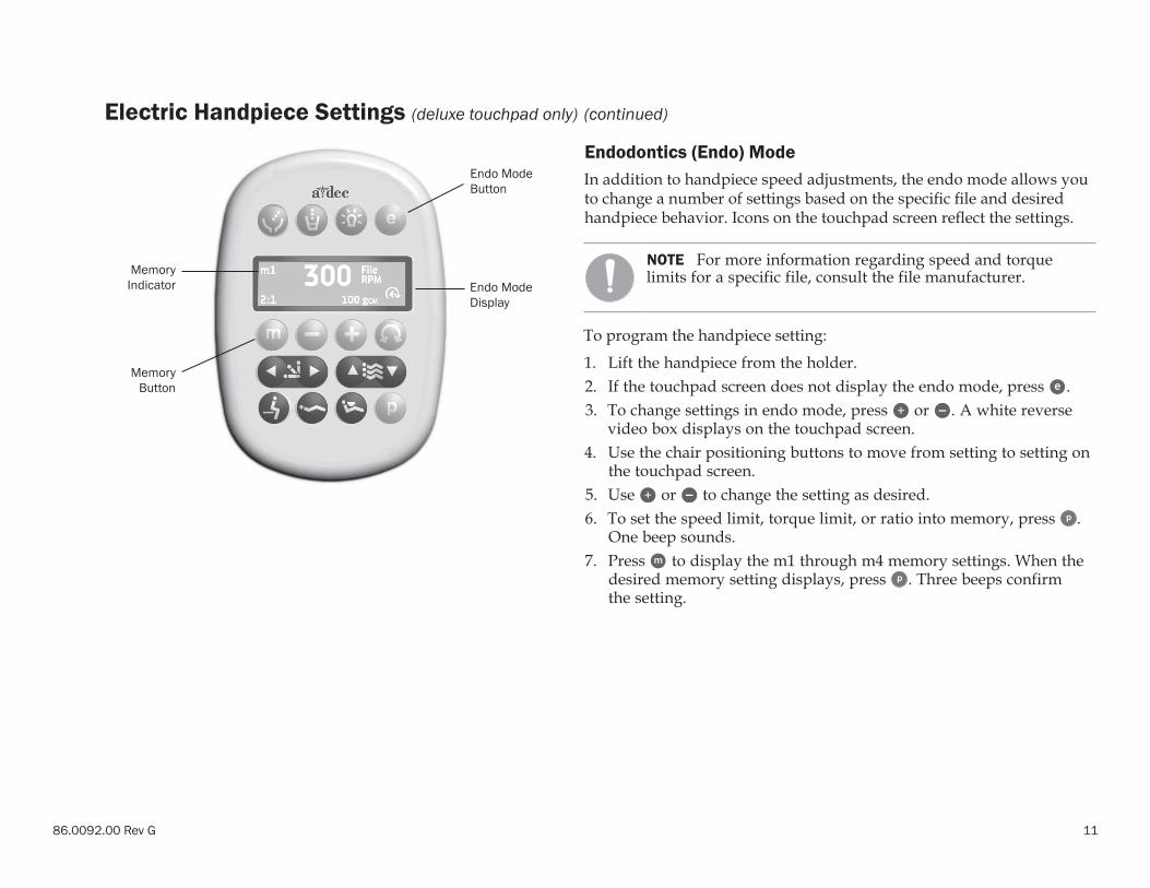
Endodontics (Endo) ModeIn addition to handpiece speed adjustments, the endo mode allows you to change a number of settings based on the specific file and desired handpiece behavior. Icons on the touchpad screen reflect the settings.
NOTE For more information regarding speed and torque limits for a specific file, consult the file manufacturer.
To program the handpiece setting:
1. Lift the handpiece from the holder.2. If the touchpad screen does not display the endo mode, press .3. To change settings in endo mode, press or . A white reverse
video box displays on the touchpad screen.4. Use the chair positioning buttons to move from setting to setting on
the touchpad screen.5. Use or to change the setting as desired.6. To set the speed limit, torque limit, or ratio into memory, press .
One beep sounds. 7. Press to display the m1 through m4 memory settings. When the
desired memory setting displays, press . Three beeps confirm the setting.
Endo Mode Button
Memory Button
Endo Mode Display
Memory Indicator
12
A-dec 300 Delivery Systems Instructions for Use Operate / Adjust
Electric Handpiece Settings (deluxe touchpad only) (continued)
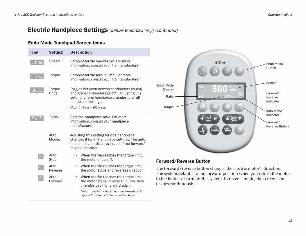
Endo Mode Touchpad Screen Icons
Icon Setting Description
Speed Setpoint for file speed limit. For more information, consult your file manufacturer.
Torque Setpoint for file torque limit. For more information, consult your file manufacturer.
Torque Units
Toggles between newton centimeters (N ·cm) and gram centimeters (g ·cm). Adjusting this setting for one handpiece changes it for all handpiece settings.Note: 1 N·cm = 102 g·cm.
Ratio Sets the handpiece ratio. For more information, consult your handpiece manufacturer.
Auto Modes
Adjusting this setting for one handpiece changes it for all handpiece settings. The auto mode indicator displays inside of the forward/reverse indicator.
Auto Stop
• When the file reaches the torque limit, the motor shuts off.
Auto Reverse
• When the file reaches the torque limit, the motor stops and reverses direction.
Auto Forward
• When the file reaches the torque limit, the motor stops, reverses 3 turns, then changes back to forward againNote: If the file is stuck, the auto forward cycle repeats three times before the motor stops.
Forward/Reverse ButtonThe forward/reverse button changes the electric motor’s direction. The system defaults to the forward position when you return the motor to the holder or turn off the system. In reverse mode, the screen icon flashes continuously.
Endo Mode Button
Forward/Reverse Button
Endo Mode Display
Speed
Auto Mode Indicator
Forward/Reverse Indicator
Torque
Ratio
86.0092.00 Rev G 13
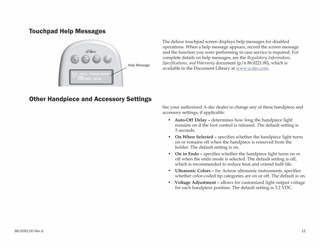
Touchpad Help MessagesThe deluxe touchpad screen displays help messages for disabled operations. When a help message appears, record the screen message and the function you were performing in case service is required. For complete details on help messages, see the Regulatory Information, Specifications, and Warranty document (p/n 86.0221.00), which is available in the Document Library at www.a-dec.com.
Other Handpiece and Accessory SettingsSee your authorized A-dec dealer to change any of these handpiece and accessory settings, if applicable:
• Auto-Off Delay – determines how long the handpiece light remains on if the foot control is released. The default setting is 5 seconds.
• On When Selected – specifies whether the handpiece light turns on or remains off when the handpiece is removed from the holder. The default setting is on.
• On in Endo – specifies whether the handpiece light turns on or off when the endo mode is selected. The default setting is off, which is recommended to reduce heat and extend bulb life.
• Ultrasonic Colors – for Acteon ultrasonic instruments, specifies whether color-coded tip categories are on or off. The default is on.
• Voltage Adjustment – allows for customized light output voltage for each handpiece position. The default setting is 3.2 VDC.
Help Message
14
A-dec 300 Delivery Systems Instructions for Use Operate / Adjust
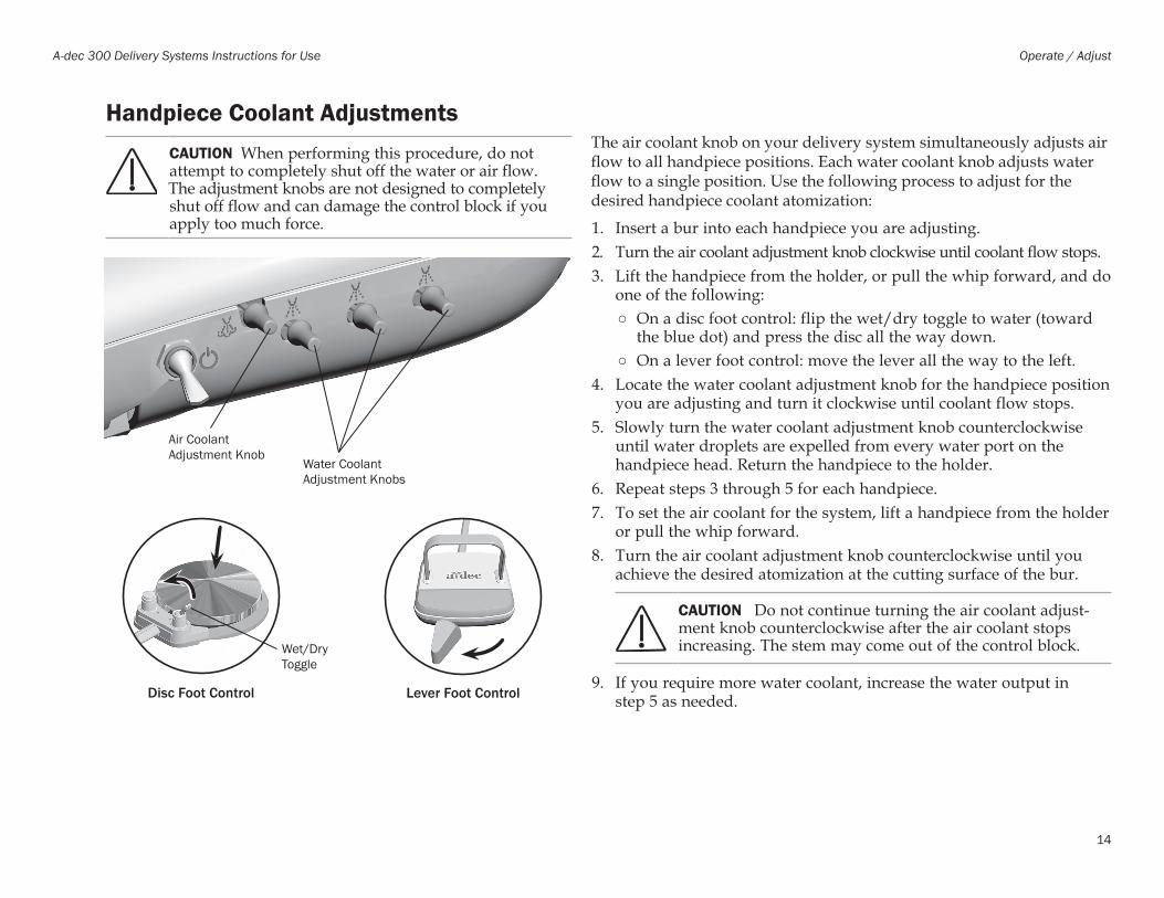
Handpiece Coolant AdjustmentsThe air coolant knob on your delivery system simultaneously adjusts air flow to all handpiece positions. Each water coolant knob adjusts water flow to a single position. Use the following process to adjust for the desired handpiece coolant atomization:
1. Insert a bur into each handpiece you are adjusting.2. Turn the air coolant adjustment knob clockwise until coolant flow stops.3. Lift the handpiece from the holder, or pull the whip forward, and do
one of the following: ○ On a disc foot control: flip the wet/dry toggle to water (toward
the blue dot) and press the disc all the way down. ○ On a lever foot control: move the lever all the way to the left.
4. Locate the water coolant adjustment knob for the handpiece position you are adjusting and turn it clockwise until coolant flow stops.
5. Slowly turn the water coolant adjustment knob counterclockwise until water droplets are expelled from every water port on the handpiece head. Return the handpiece to the holder.
6. Repeat steps 3 through 5 for each handpiece.7. To set the air coolant for the system, lift a handpiece from the holder
or pull the whip forward.8. Turn the air coolant adjustment knob counterclockwise until you
achieve the desired atomization at the cutting surface of the bur.
CAUTION Do not continue turning the air coolant adjust-ment knob counterclockwise after the air coolant stops increasing. The stem may come out of the control block.
9. If you require more water coolant, increase the water output in step 5 as needed.
Water Coolant Adjustment Knobs
Lever Foot Control
Air Coolant Adjustment Knob
Wet/Dry Toggle
Disc Foot Control
CAUTION When performing this procedure, do not attempt to completely shut off the water or air flow. The adjustment knobs are not designed to completely shut off flow and can damage the control block if you apply too much force.
86.0092.00 Rev G 15
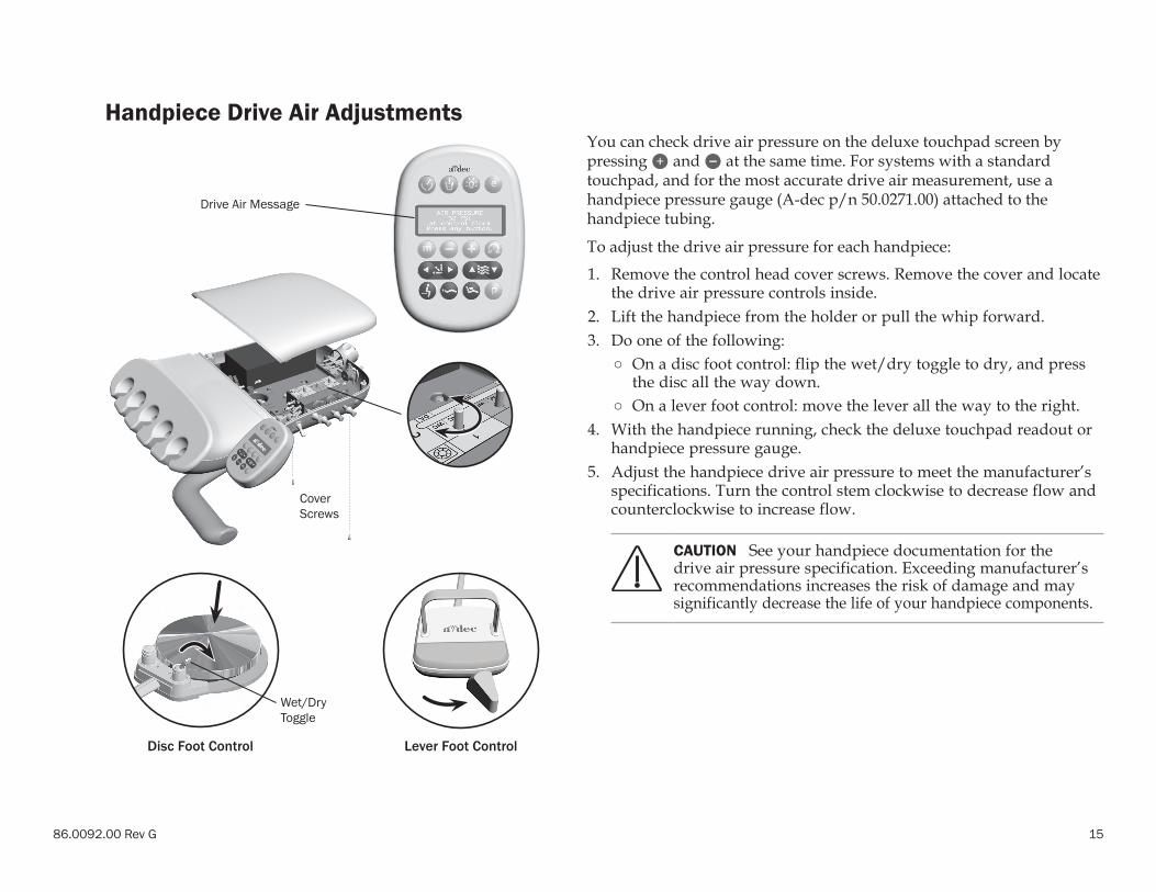
Drive Air Message
Cover Screws
Handpiece Drive Air AdjustmentsYou can check drive air pressure on the deluxe touchpad screen by pressing and at the same time. For systems with a standard touchpad, and for the most accurate drive air measurement, use a handpiece pressure gauge (A-dec p/n 50.0271.00) attached to the handpiece tubing.
To adjust the drive air pressure for each handpiece:
1. Remove the control head cover screws. Remove the cover and locate the drive air pressure controls inside.
2. Lift the handpiece from the holder or pull the whip forward.3. Do one of the following:
○ On a disc foot control: flip the wet/dry toggle to dry, and press the disc all the way down.
○ On a lever foot control: move the lever all the way to the right.4. With the handpiece running, check the deluxe touchpad readout or
handpiece pressure gauge.5. Adjust the handpiece drive air pressure to meet the manufacturer’s
specifications. Turn the control stem clockwise to decrease flow and counterclockwise to increase flow.
CAUTION See your handpiece documentation for the drive air pressure specification. Exceeding manufacturer’s recommendations increases the risk of damage and may significantly decrease the life of your handpiece components.
Wet/Dry Toggle
Disc Foot Control Lever Foot Control
16
A-dec 300 Delivery Systems Instructions for Use Operate / Adjust
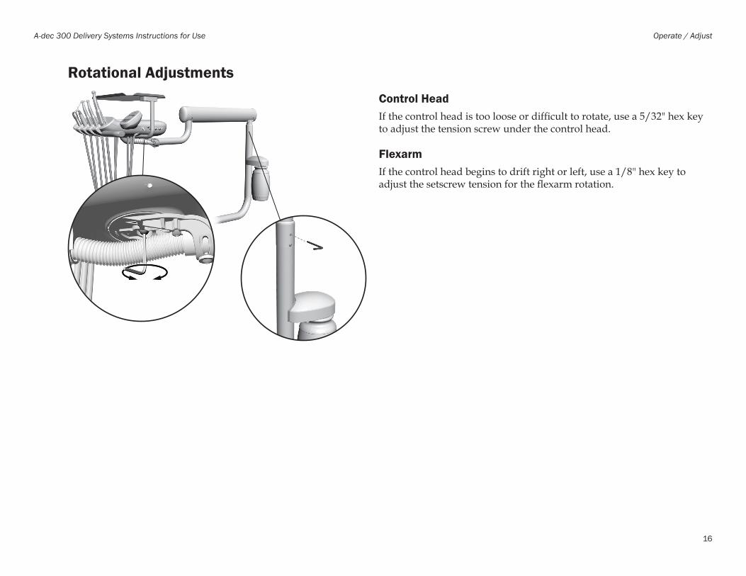
Rotational AdjustmentsControl HeadIf the control head is too loose or difficult to rotate, use a 5/32" hex key to adjust the tension screw under the control head.
FlexarmIf the control head begins to drift right or left, use a 1/8" hex key to adjust the setscrew tension for the flexarm rotation.
86.0092.00 Rev G 17
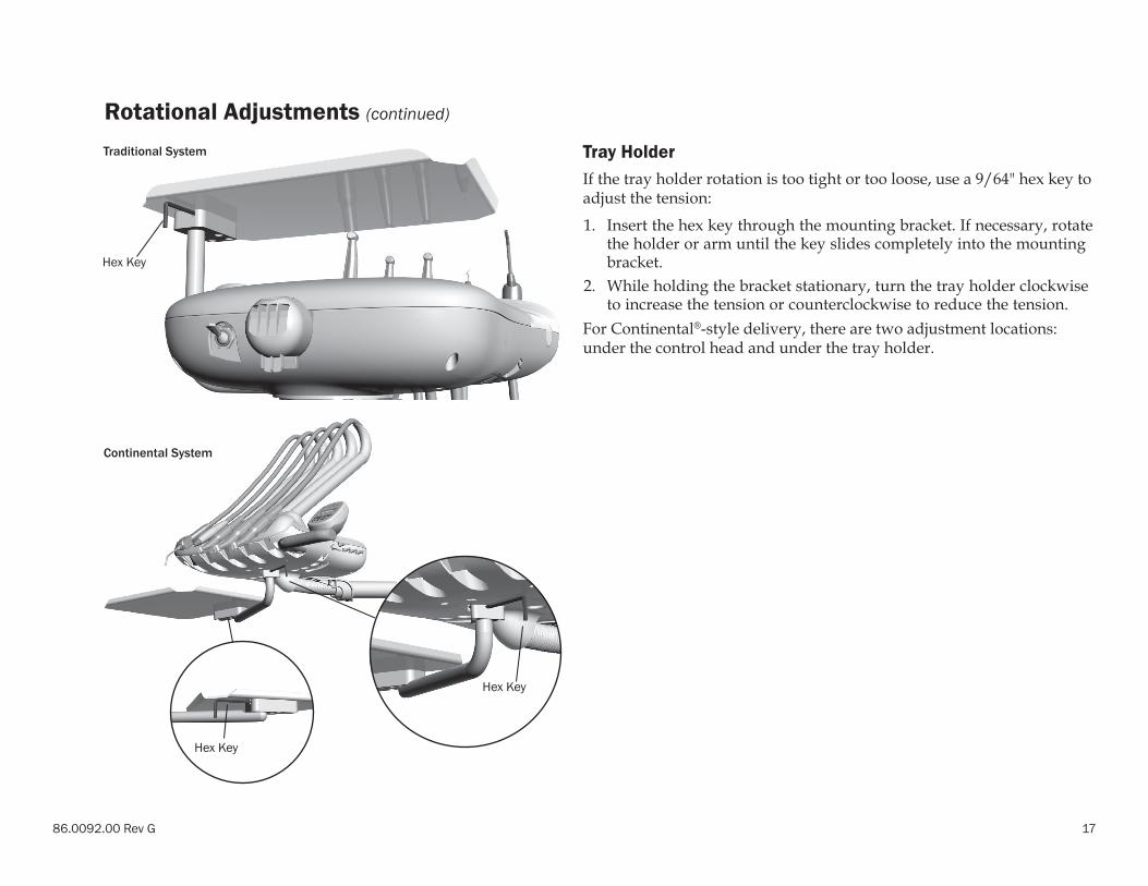
Rotational Adjustments (continued)
Tray HolderIf the tray holder rotation is too tight or too loose, use a 9/64" hex key to adjust the tension:
1. Insert the hex key through the mounting bracket. If necessary, rotate the holder or arm until the key slides completely into the mounting bracket.
2. While holding the bracket stationary, turn the tray holder clockwise to increase the tension or counterclockwise to reduce the tension.
For Continental®-style delivery, there are two adjustment locations: under the control head and under the tray holder.
Continental System
Hex Key
Hex Key
Traditional System
Hex Key
18
A-dec 300 Delivery Systems Instructions for Use Operate / Adjust
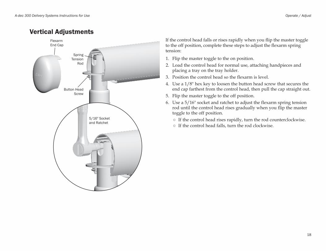
Vertical AdjustmentsIf the control head falls or rises rapidly when you flip the master toggle to the off position, complete these steps to adjust the flexarm spring tension:
1. Flip the master toggle to the on position. 2. Load the control head for normal use, attaching handpieces and
placing a tray on the tray holder.3. Position the control head so the flexarm is level.4. Use a 1/8" hex key to loosen the button head screw that secures the
end cap farthest from the control head, then pull the cap straight out.5. Flip the master toggle to the off position. 6. Use a 5/16" socket and ratchet to adjust the flexarm spring tension
rod until the control head rises gradually when you flip the master toggle to the off position.
○ If the control head rises rapidly, turn the rod counterclockwise. ○ If the control head falls, turn the rod clockwise.
5/16" Socket and Ratchet
Button Head Screw
Spring Tension
Rod
Flexarm End Cap
86.0092.00 Rev G 19
Clean / Maintain
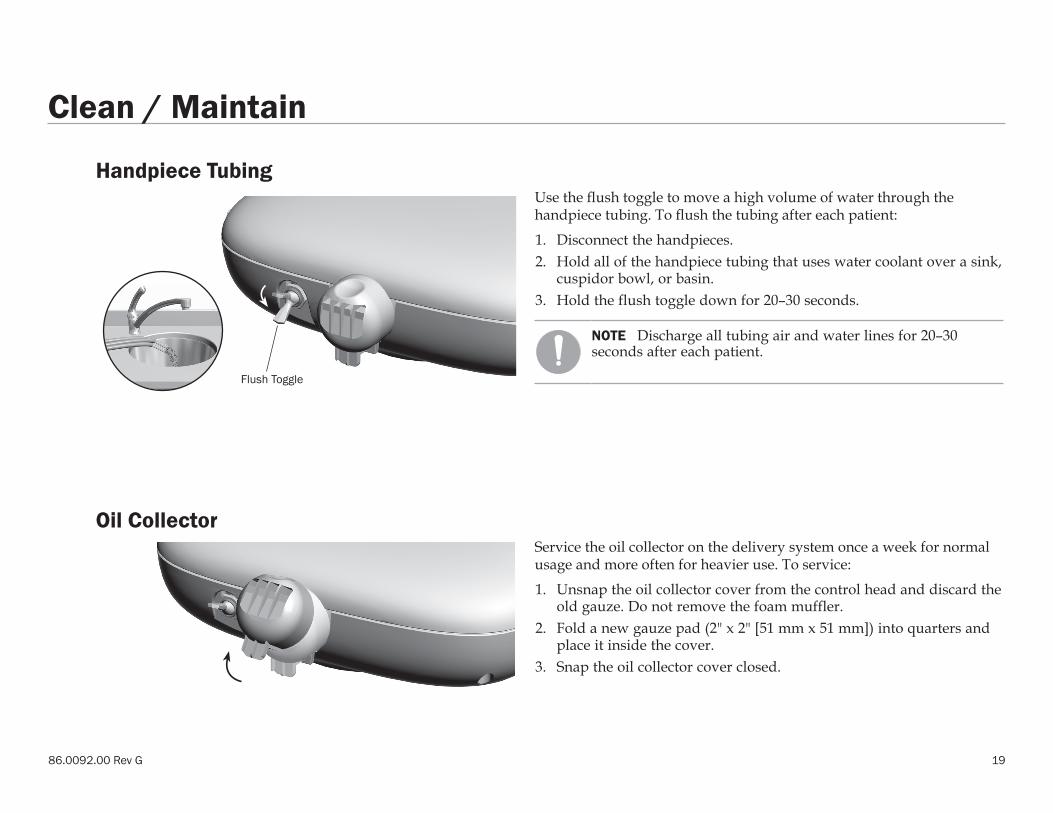
Handpiece Tubing Use the flush toggle to move a high volume of water through the handpiece tubing. To flush the tubing after each patient:
1. Disconnect the handpieces.2. Hold all of the handpiece tubing that uses water coolant over a sink,
cuspidor bowl, or basin.3. Hold the flush toggle down for 20–30 seconds.
NOTE Discharge all tubing air and water lines for 20–30 seconds after each patient.
Oil CollectorService the oil collector on the delivery system once a week for normal usage and more often for heavier use. To service:
1. Unsnap the oil collector cover from the control head and discard the old gauze. Do not remove the foam muffler.
2. Fold a new gauze pad (2" x 2" [51 mm x 51 mm]) into quarters and place it inside the cover.
3. Snap the oil collector cover closed.
Flush Toggle
20
A-dec 300 Delivery Systems Instructions for Use Clean / Maintain
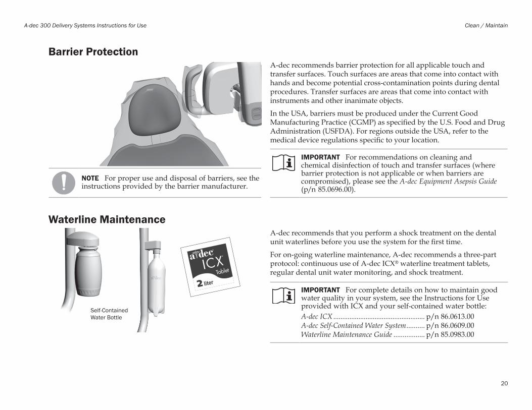
Barrier ProtectionA-dec recommends barrier protection for all applicable touch and transfer surfaces. Touch surfaces are areas that come into contact with hands and become potential cross-contamination points during dental procedures. Transfer surfaces are areas that come into contact with instruments and other inanimate objects.
In the USA, barriers must be produced under the Current Good Manufacturing Practice (CGMP) as specified by the U.S. Food and Drug Administration (USFDA). For regions outside the USA, refer to the medical device regulations specific to your location.
IMPORTANT For recommendations on cleaning and chemical disinfection of touch and transfer surfaces (where barrier protection is not applicable or when barriers are compromised), please see the A-dec Equipment Asepsis Guide (p/n 85.0696.00).
Waterline Maintenance A-dec recommends that you perform a shock treatment on the dental unit waterlines before you use the system for the first time.
For on-going waterline maintenance, A-dec recommends a three-part protocol: continuous use of A-dec ICX® waterline treatment tablets, regular dental unit water monitoring, and shock treatment.
IMPORTANT For complete details on how to maintain good water quality in your system, see the Instructions for Use provided with ICX and your self-contained water bottle:A-dec ICX ................................................... p/n 86.0613.00A-dec Self-Contained Water System .......... p/n 86.0609.00Waterline Maintenance Guide ................. p/n 85.0983.00
NOTE For proper use and disposal of barriers, see the instructions provided by the barrier manufacturer.
Self-Contained Water Bottle
86.0092.00 Rev G 21
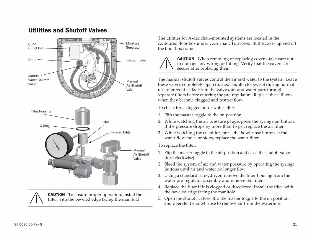
Utilities and Shutoff ValvesThe utilities for A-dec chair-mounted systems are located in the contoured floor box under your chair. To access, lift the cover up and off the floor box frame.
CAUTION When removing or replacing covers, take care not to damage any wiring or tubing. Verify that the covers are secure after replacing them.
The manual shutoff valves control the air and water to the system. Leave these valves completely open (turned counterclockwise) during normal use to prevent leaks. From the valves, air and water pass through separate filters before entering the pre-regulators. Replace these filters when they become clogged and restrict flow.
To check for a clogged air or water filter:
1. Flip the master toggle to the on position.2. While watching the air pressure gauge, press the syringe air button.
If the pressure drops by more than 15 psi, replace the air filter.3. While watching the cuspidor, press the bowl rinse button. If the
water flow fades or stops, replace the water filter.
To replace the filter:
1. Flip the master toggle to the off position and close the shutoff valve (turn clockwise).
2. Bleed the system of air and water pressure by operating the syringe buttons until air and water no longer flow.
3. Using a standard screwdriver, remove the filter housing from the water pre-regulator assembly and remove the filter.
4. Replace the filter if it is clogged or discolored. Install the filter with the beveled edge facing the manifold.
5. Open the shutoff valves, flip the master toggle to the on position, and operate the bowl rinse to remove air from the waterline.
Manual Water Shutoff Valve
Manual Air Shutoff Valve
Drain Vacuum Line
Quad Outlet Box
Moisture Separator
CAUTION To ensure proper operation, install the filter with the beveled edge facing the manifold.
Filter Housing
Filter
Manual Air Shutoff Valve
O-Ring
Beveled Edge

22
A-dec 300 Delivery Systems Instructions for Use Clean / Maintain
Utilities and Shutoff Valves (continued)The manual water shutoff valves include a screen to prevent larger debris from entering the system. Periodically check and replace this screen to ensure unrestricted water flow.
To replace the water screen:
1. Flip the master toggle to the off position and close the shutoff valves (turn clockwise).
2. Use a 5/8" or adjustable wrench to loosen the compression nut on the manual water shutoff valve. Then pull the water regulator out of the shutoff valve.
3. Remove the old screen and replace with the new screen.4. Reposition the water regulator in the manual shutoff valve outlet
and tighten the compression nut.5. Open the manual water shutoff valve (turn counterclockwise) and
flip the master toggle to the on position. Check the fittings for leaks.
Manual Water Shutoff Valve
Filter Housing
Water Regulator
Water Screen
86.0092.00 Rev G 23
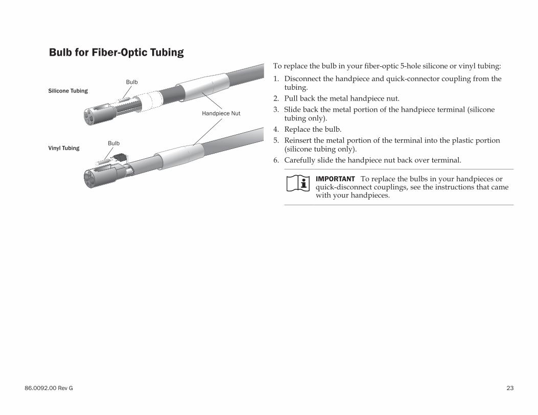
Bulb for Fiber-Optic TubingTo replace the bulb in your fiber-optic 5-hole silicone or vinyl tubing:
1. Disconnect the handpiece and quick-connector coupling from the tubing.
2. Pull back the metal handpiece nut.3. Slide back the metal portion of the handpiece terminal (silicone
tubing only).4. Replace the bulb.5. Reinsert the metal portion of the terminal into the plastic portion
(silicone tubing only).6. Carefully slide the handpiece nut back over terminal.
IMPORTANT To replace the bulbs in your handpieces or quick-disconnect couplings, see the instructions that came with your handpieces.
Silicone Tubing
Vinyl Tubing
Handpiece Nut
Bulb
Bulb

24
A-dec 300 Delivery Systems Instructions for Use Specifications
Specifications
Minimum Air, Water, and Vacuum Service RequirementsAir: 2.5 scfm (71 SL/min) at 80 - 125 psi (550 - 860 kPa) minimumWater: 1.5 gpm (5.7 L/min) at 60±20 psi (410±140 kPa) minimumVacuum:
(wet): 9 scfm (255 SL/min) at 10±2 inches of Hg (34±7 kPa) minimun
(dry): 12 scfm (340 SL/min) at 4.5±1 inches of Hg (16±3.5 kPa) minimum
IMPORTANT For electrical specifications, identification of symbols, and other regulatory requirements, see the Regulatory Information, Specifications, and Warranty document (p/n 86.0221.00), which is available in the Document Library at www.a-dec.com.
NOTE Specifications are subject to change without notice. Requirements may vary depending on your location. For more information, contact your authorized A-dec dealer.
Warranty
Warranty information is provided in the Regulatory Information, Specifications, and Warranty document (p/n 86.0221.00), which is available in the Document Library at www.a-dec.com.

86.0092.00 Rev GCopyright 2017 A-dec Inc.
All rights reserved.IFUcov5
A-dec United KingdomEU Authorized RepresentativeAustin House, 11 Liberty WayNuneaton, Warwickshire CV11 6RZEngland Tel: 0800.ADEC.UK (2332.85) within UKTel: +44.(0).24.7635.0901 outside UK
A-dec AustraliaUnit 85-9 Ricketty StreetMascot, NSW 2020AustraliaTel: 1.800.225.010 within AUSTel: +61.(0).2.8332.4000 outside AUS
A-dec Headquarters2601 Crestview DriveNewberg, Oregon 97132United StatesTel: 1.800.547.1883 within USA/CANTel: +1.503.538.7478 outside USA/CANFax: 1.503.538.0276www.a-dec.com
A-dec ChinaA-dec (Hangzhou) Dental Equipment Co., Ltd.528 Shunfeng Road Qianjiang Economic Development ZoneHangzhou 311106, Zheijiang, ChinaTel: 400.600.5434 within ChinaTel: +0571.89026088 outside China
ÍvÈ.ÇÂ|È.009Î