Embed Size (px)
Citation preview

A-dec Dental Lights and Monitor Mounts
Service Guide
Copy
©2012
A-dec includfitnesserrors furnishdocumdocumwarran
No paany forecordwritten
Trade
A-dec,CenturCollecregistereliabltrademmaniptradem
Certainsymbois stric
ed with A-dec equipment as mandated by ation is delivered in the equipment’s
e Regulatory Information and Specifications ation, please go to the Document Library at
our local authorized A-dec dealer. To find ec.com.
the A-dec Dental Lights and Monitor Mounts . The Service Reference contains flow eakdown for lights and monitor mounts. ation is available in both this document and
right
A-dec Inc. All rights reserved.
Inc. makes no warranty of any kind with regard to this material, ing, but not limited to, the implied warranties of merchantability and for a particular purpose. A-dec Inc. shall not be held liable for any contained herein or any consequential or other damages concerning the ing, performance or use of this material. The information in this ent is subject to change without notice. If you find any problems in the entation, please report them to us in writing. A-dec Inc. does not t that this document is error-free.
rt of this document may be copied, reproduced, altered, or transmitted in rm or by any means, electronic or mechanical, including photocopying, ing, or by any information storage and retrieval system, without prior permission from A-dec Inc.
marks and Additional Intellectual Property Rights
the A-dec logo, A-dec 500, A-dec 300, Cascade, Cascade Master Series, y Plus, Continental, Decade, ICX, ICV, Performer, Preference, Preference
tion, Preference ICC, and Radius are trademarks of A-dec Inc. and are red in the U.S. and other countries. A-dec 200, Preference Slimline, and ecreativesolutions are also trademarks of A-dec Inc. None of the arks or trade names in this document may be reproduced, copied, or
ulated in any manner without the express, written approval of the arkowner.
touchpad symbols are proprietary to A-dec Inc. Any use of these ls, in whole or in part, without the express written consent of A-dec Inc. tly prohibited.
Regulatory Information
Regulatory information is providagency requirements. This informInstructions for Use or the separatdocument. If you need this informwww.a-dec.com.
Product Service
For service information, contact yyour local dealer, go to www.a-d
Service Reference
This document is a companion toService Reference (p/n 86.0328.00)diagrams and illustrated parts brCircuit board component informthe Service Reference.

A - D E C D E N T A O U N T S
L L I G H T S A N D M O N I T O R MS E R V I C E G U I D E
2
1 INTRODUCTRegulatory Sym
Get Support ..Customer Se
Other SourcesDental LightGenuine A-dA-dec IllustrElectronic DSerial and M
2 A-DEC DENTDental Light S
Dental Light M
Dental Light C
Dental Light ODental LightPower and In
A-dec LEA-dec 57On/Off aA-dec 37On/Off aHalogen Auto On/
Dental LightA-dec 57A-dec 37
Dental LightHalogen LED Dent
Dental Light AA-dec LED D
stments ........................................... 19nt ................................................. 19al Rotation Adjustment ........................ 19ight (Halogen 3-Axis)
................................................20ion ................................................. 20on ................................................. 20ation .............................................. 21 .................................................... 21...................................................... 21ogen 2-Axis) ................................................22...................................................... 22...................................................... 22ance Adjustment...........................22
onnections ............................23oard Components...........................24...................................................... 24dentification ..................................... 25...................................................... 25 Circuit Board ................................... 26N Adapter Board ................................ 27oard ............................................... 2777L) Wiring.................................28
...................................................... 28
...................................................... 29ius Arm Mounted ............................... 30
...................................................... 31
...................................................... 32
...................................................... 33
...................................................... 34ight (Halogen 3-Axis)
................................................36ut Functions .................................... 36ents .............................................. 37 ..................................................... 37rcuit Board..................................38gs .................................................. 38
C O N T
ION........................................................5bols............................................................5
...................................................................6rvice....................................................................6
of Information ...............................................6s and Monitor Mounts Service Reference .........................6ec Parts Catalog ......................................................6ated Parts Breakdown ...............................................6ocumentation .........................................................6odel Numbers .........................................................7
AL LIGHTS...............................................9pecifications................................................. 10
ounting Locations.......................................... 11
ircuit Breaker Locations .................................. 12
perations .................................................... 13 Touchpad Controls................................................. 13tensity Settings .................................................... 14
D Dental Light Manual On/Off and Intensity ........................... 141/572 and 6300 Dental Light (Halogen 3-Axis) Manual nd Intensity .................................................................. 141/372 Dental Light (Halogen 2-Axis) Manual nd Intensity .................................................................. 14Dental Light Intensity Switch Voltage Measurements ................. 15Off Function ................................................................ 15 Bulb Replacement ................................................. 161/572 and 6300 Dental Light (Halogen3-Axis) .......................... 161/372 Dental Light (Halogen 2-Axis) ..................................... 17 Shield Cleaning .................................................... 18Dental Light Shield ......................................................... 18al Light Shield .............................................................. 18
djustments .................................................. 19ental Light Rotation Adjustments................................ 19
LED Light Range of Motion AdjuLED Light Forward Tilt AdjustmeLED Light Horizontal and Diagon
A-dec 571/572 and 6300 Dental LRotation Adjustments .............
571/572/6300 Light Head Rotat571/572/6300 Horizontal Rotati571/572/6300 Diagonal Axis Rot571/572/6300 Vertical Rotation571/572/6300 Focus ............
A-dec 371/372 Dental Light (HalRotation Adjustments .............
371/372 Horizontal Rotation ..371/372 Vertical Rotation ......
Dental Light Flexarm Counterbal
Dental Light Wiring and Power CA-dec LED Dental Light Circuit B
LED Driver Circuit Board .......LED Dental Light Circuit Board ILED Indicator Light Board .....LED Dental Light Indicator LightLED Dental Light Terminal to CALED Dental Light CAN Adaptor B
A-dec LED Dental Light (570L — 5571L on an A-dec 511 Chair ....571L on an A-dec 311 Chair ....572L on an A-dec 511 Chair, Rad574L Cabinet Mounted ..........575L Wall Mounted ..............576L Ceiling Mounted ...........577L Track Mounted .............
A-dec 571/572 and 6300 Dental LCircuit Board Components .......
571/572/6300 Dental Light Outp511 Chair Circuit Board Compon511 Circuit Board Identification
A-dec 6300 Dental Light Relay Ci6300 Dental Light Output Settin
E N T S

86.0326 3
A-
A-
A-Bo
A-
Denta
S ......................................... 59...............................................60.....................................................60
(Clutch).....................................61.....................................................61...........................................................61...........................................................61...........................................................61ent (Support Side, Model 561) ....................62
(Track Mount) ...................................62
(Handle) ....................................63...........................................................63...........................................................63
.00 Rev B
6300 Dental Light Relay Circuit Board LED Identification ....................... 396300 Dental Light Relay Circuit Board Identification ............................ 39
dec 571/572 and 6300 Dental Light (Halogen 3-Axis) Wiring ............ 406300 Ceiling, Wall, and Preference Mount Switch and Data Line Connections ................................................................ 406300 Track Light Switch Connections and Data Line (2004 and Later) ........ 416300 Track Light Switch Connections and Data Line (2003 and Earlier) ...... 42A-dec 571/572 and 6300 Dental Light .............................................. 43
dec 571/572 and 6300 Dental Light (Halogen 3-Axis) Transformer ..... 44100 VAC Transformer Wiring ......................................................... 44110-120 VAC Transformer Wiring .................................................... 44220-240 VAC Transformer Wiring .................................................... 45
dec 371/372 Dental Light (Halogen 2-Axis) Circuit ard Components ................................................................ 46
A-dec 311 Dental Chair Circuit Board for 371/372 Dental Light on an A-dec 311 Chair ................................................................ 46371/372 Dental Light Output Settings ............................................. 46311 Chair Circuit Board LED Identification ........................................ 47311 Chair Circuit Board Identification ............................................. 47A-dec 511 Chair Board Components for 371/372 Dental Light on an A-dec 511 Chair ................................................................ 48371/372 Dental Light Output Settings ............................................. 48511 Chair Circuit Board LED Identification ........................................ 49511 Chair Circuit Board Identification ............................................. 49A-dec 371/372 Dental Light Relay Circuit Board ................................. 50371/372 Dental Output Settings .................................................... 50371/372 Dental Light Relay Board LED Identification ........................... 51371/372 Dental Light Relay Circuit Board Identification ........................ 51
dec 371/372 Dental Light (Halogen 2-Axis) Wiring ........................ 52371/372 Dental Light Connections .................................................. 52On/Off Switch ......................................................................... 52A-dec 371/372 Dental Light Wire Connections on an A-dec 311 Chair ........ 53A-dec 371/372 Dental Light Wire Connections on an A-dec 511 Chair ........ 54A-dec 371/372 Dental LIght Wire Connections on Cascade, Decade, Performer, Priority Chairs ............................................................ 55
l Light Troubleshooting .............................................. 56
3 A-DEC MONITOR MOUNTMonitor Mount Overview.....
Monitor Mount Specification
Monitor Mount Adjustments Friction Adjustment..........
Tilt Friction .................Drift Friction ................Clutch Assembly ...........Tray Holder Tension Adjustm
Panning Friction Adjustment
Monitor Mount Adjustments Tilt Adjustment .............Horizontal Pivot ............

86.0326.00 Rev B 5
1INTROD
This guide provimonitor mounts.maintenance of d
RegulatoThe following re
CAUTIONperform
NOTE Nimportan
TIP Tipmainten
WARNINGinstructi
CAUTIONresult in
DANGERcertain e
icates potential infection if instructions
ates areas in which to refer to or use
UCTION
des service information for the A-dec dental lights and Users of this guide should understand basic operation and ental and medical equipment.
ry Symbolsgulatory symbols may appear throughout the document.
Possible injury or equipment damage. Service to be ed by trained personnel only.
otes indicate additional information, and when it is t that instructions are followed.
s indicate tips or tricks to make installation, use, or ance easier.
Warning indicates potential severe injury or death if ons are not followed properly.
Caution indicates when failure to follow instructions could damage to product or minor injury.
Danger indicates warnings of dangerous voltage and of lectrical shock.
BIOHAZARD Biohazard indare not properly followed.
IMPORTANT Important indicspecific instructions.

A-d Introduction 6
G
CuFous
U.A-26NeTeTewwww
UnA-AuNuEnTeTeww
AuA-UnMAuTe1.8ww
WPa
formation
Mounts Service Referencets illustrated parts breakdown content, r Mounts Service Reference
logg, p/n 85.5000.00, provides part number erviceable parts. This catalog details products which are no longer
fer to this catalog for additional details on
eakdownIPB), p/n 85.0851.00, contains illustrated,
art numbers and descriptions for ced before 2004.
ts are available as electronic documents w.a-dec.com). Documents (including es, and other technical information) can be ite, select Document Library in the upper-cation for current detail on products and
ec Dental Lights and Monitor Mounts Service Guide
et Support
stomer Servicer questions not addressed in this document, contact A-dec Customer Service ing contact information for your region.
S. and Canadadec Inc.01 Crestview Drivewberg, OR 97132 USAl: 1.800.547.1883 within US and Canadal: 1.503.538.7478 outside US and Canada
w.a-dec.comw.a-dec.biz
ited Kingdomdec United Kingdomstin House, 11 Liberty Wayneaton, Warwickshire CV11 6RZglandl: 0800 ADECUK (233285) within UKl: 44 24 7635 0901 outside UK
w.a-dec.co.uk
straliadec Australiait 8, 5-9 Ricketty St.
ascot, NSW 2020 stralia
l: (02) 8332 400000.225.010w.a-dec.com.au
eb Contactrtner Resources websites: www.a-dec.biz.
Other Sources of In
Dental Lights and MonitorFor Dental Lights and Monitor Mounsee the A-dec Dental Lights and Monito(p/n 86.0328.00).
Genuine A-dec Parts CataThe Genuine A-dec Service Parts Cataloand ordering information for A-dec sservice parts for current products andmanufactured but still supported. Reparts found in the service guide.
A-dec Illustrated Parts BrThe A-dec Illustrated Parts Breakdown (exploded views of assemblies with passociated parts for products introdu
Electronic DocumentationThe latest versions of A-dec documen(PDF files) on the A-dec website (wwinstallation instructions, service guidviewed or downloaded. On the websright corner of the page. Check this lotechnical information.

86 Introduction 7
SePrmohe
ThmathDedig
mples to reference how to identify serial/
s (Dental Light Examples Shown)
Letter Month
G July
H August
I September
J October
K November
L December
37111F82615
DENTALLIGHT
erial mber
odel mber
Products Manufactured June 2011 and after
.0326.00 Rev B
rial and Model Numbersoduct serial and model number information can be found on the serial/del number labels. When contacting customer service, the serial number
lps identify the product and when it was manufactured.
e first letter of the serial number indicates the month the product was nufactured. For products manufactured before June 2011, the first digit of
e serial number indicates the year of manufacture (for example, L0 = cember 2010). For products manufactured June 2011 and after, the first two its indicate the year of manufacture (for example, 11F = June 2011).
Use the following table and label examodel number information.
Month Identification Table
Serial Number Label Example
Letter Month
A January
B February
C March
D April
E May
F June
DENTALLIGHT 371
Products Manufactured before June 2011
SNu
MNu
A-d Introduction 8
ec Dental Lights and Monitor Mounts Service Guide
86.0326.00 Re 9
2A-DE
This section
A-dec LED
A-dec 571
alogen 2-Axis)
v B
C DENTAL L IGHTS
provides service, usage, adjustments, and maintenance content for A-dec dental lights.
Dental Light (570L — 577L)
/572 and 6300 Dental Light (Halogen3-Axis)
A-dec 371/372 Dental Light (H

A-d A-dec Dental Lights 10
D
* F Specifications manual (p/n 86.0221.00) inc** lants, and adhesives. This mode uses a me
y. For more information, contact your
dec 371/372 Dental Light alogen2-Axis)
In 0 /110-120 / 220 - 240 VAC
F " - 27" (305" - 686 mm)
B artz Xenon Halogen, single-end prongs
B V / 95W
C 00 Kelvin
L " x 6.7" at 27.6" (99 mm x 170 mm at 700 mm)
N mposite: 8,000 lux (743 fc)gh: 24,000 lux (2230 fc)
H(
5
ec Dental Lights and Monitor Mounts Service Guide
ental Light Specifications
or electrical specifications, identification of symbols, and other regulatory requirements, refer to the Regulatory Information andluded with the dental equipmentThe LED cure-safe mode provides effective illumination while preventing the premature curing of photo-initiated composites, seadium intensity light setting and a non-reactive wavelength of light.
NOTE Specifications are subject to change without notice. Some requirements may vary from country to countrauthorized A-dec dealer.
A-dec LED Dental Light (570L - 577L)A-dec 571/572 and 6300 Dental Light (Halogen 3-Axis)
A-(H
put Voltage 15 watts maximum * 100 / 120 / 240 VAC 10
ocal Range 16" - 30" (400 mm - 750 mm) 18" - 31" (457 - 787 mm) 12
ulb n/a Quartz Xenon Halogen, single-end prongs Qu
ulb Rating LED: White HBLED, 88-92 CRI 17V / 95W 17
olor temperature White 5000 Kelvin 5,000 Kelvin 5,0
ight pattern 5.7" x 3.8" at 27.6" (145 mm x 95 mm at 700 mm) 3.3" x 6.3" at 27.6" (85 mm x 160 mm at 700 mm) 3.9
ominal Light Intensity ** Cure-safe Mode: 25,000 lux (2323 fc)High: 30,000 lux (2787 fc)Medium: 25,000 lux (2323 fc)Low: 15,000 lux (1394 fc)
High: 24,000 lux (2230 fc)Medium: 20,000 lux (1858 fc)Low: 8,000 lux (743 fc)
CoHi
eat Output BTU per Hour)
24 325 32

86 A-dec Dental Lights 11
D
C(
71/372, 571/572 Dental Light on 500 Chair Support Side Mount
.0326.00 Rev B
ental Light Mounting Locations
abinet-MountedLED and 6300)
Ceiling-Mounted(LED and 6300)
Track-Mounted(LED and 6300)
Wall-Mounted(LED and 6300)
Radius Style (LED, 371/372, 571/572, 6300) Dental Light on A-dec 500 Chair Support Mount
LED, 371/372, 571/572 Dental Light on A-dec 300 Chair and 2" Post Mount Support Mount
LED, 3A-dec

A-d A-dec Dental Lights 12
DA t the wiring to ensure there are no shorts, an ion varies by chair. For non-chair based lig
CL
A
M
A
M
CPm
U
r Location
ec Dental Lights and Monitor Mounts Service Guide
ental Light Circuit Breaker Locationscircuit breaker will interrupt the flow of electricity under abnormal conditions. If the circuit breaker should trip, inspecd reset by pushing the circuit breaker. If the circuit breaker for the dental light is located on the power supply, its locathts, the operatory circuit breaker is used.
hair Model/ocation
Circuit Breaker Location
-dec 311
otor Pump
-dec 511
otor Pump
ascade,® Decade,® erformer,® early odel A-dec chairs
tility floor box
CB 1MAINS
INPUTVACUUM RELAY13
A @ 25
0V~ M
AXPOWER ON MODE
ASSISTANT'S ARM
& CONTROL HEAD
CB 3
8A MAX
OUTPUT0V
~ 24V~
DATA
CB 5CB 4MAINS OUTPUT
POWER 4A MAX
SIDESUPPORT
ARM DENTALLIGHT
MASTER TOGGLE
CONTROL OF POWER
SWITCH ON
NC COM N
ONO CONNECTION
REQUIRED
SWITCH OFF
CB 2
CONNECT AIR SUPPLY
FROM MASTER TOGGLE
10AMP
10AMP
10AMP
10AMP
10AMP
10AMP 10
AMP
Before June 2012
Effective June 2012
Mounting Location Circuit Breake
Track Mount
Cabinet Mount
Post Mount: Cascade,® Decade,® Performer,® early model A-dec chairs
Ceiling Mount
Wall Mount
86 A-dec Dental Lights 13
D
DeDe to turn on the light, and press and hold th
DeBu
Dental Light Indicator
.0326.00 Rev B
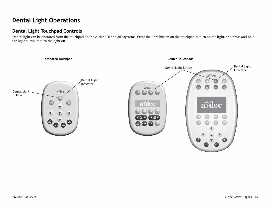
ental Light Operations
ntal Light Touchpad Controlsntal light can be operated from the touchpad on the A-dec 300 and 500 systems. Press the light button on the touchpad
e light button to turn the light off.
Standard Touchpad
ntal Light tton
Dental Light Indicator
Deluxe Touchpads
Dental Light Button
A-d A-dec Dental Lights 14
Po
A-Thshen
A-OnThbedeoff
Halogen 2-Axis) Manual On/Off
the light and to toggle between intensities. t button to activate the light and to toggle
MoPa
372 Dental Light, medium and s are available if preferred over high
-dec Customer Service for instructions.
ec Dental Lights and Monitor Mounts Service Guide
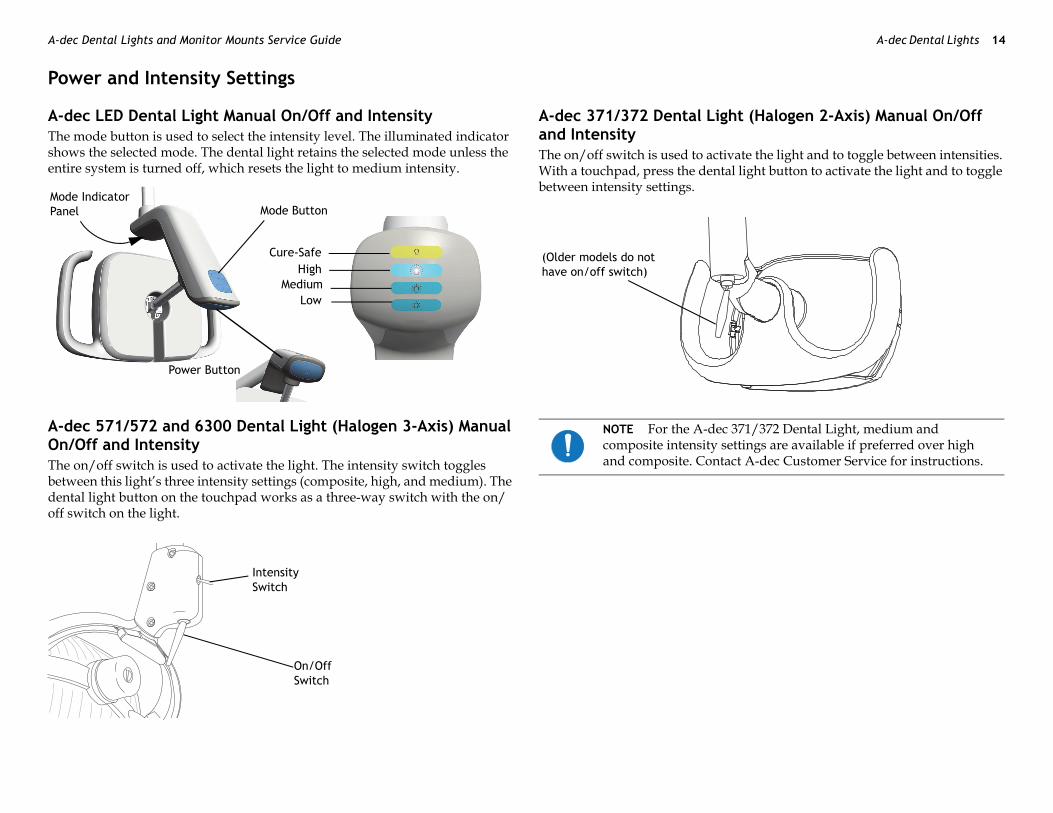
wer and Intensity Settings
dec LED Dental Light Manual On/Off and Intensity e mode button is used to select the intensity level. The illuminated indicator ows the selected mode. The dental light retains the selected mode unless the tire system is turned off, which resets the light to medium intensity.
dec 571/572 and 6300 Dental Light (Halogen 3-Axis) Manual/Off and Intensity
e on/off switch is used to activate the light. The intensity switch toggles tween this light’s three intensity settings (composite, high, and medium). The ntal light button on the touchpad works as a three-way switch with the on/ switch on the light.
A-dec 371/372 Dental Light (and IntensityThe on/off switch is used to activate With a touchpad, press the dental lighbetween intensity settings.
Mode Button
Cure-SafeHigh
MediumLow
de Indicator nel
Power Button
Intensity Switch
On/Off Switch
NOTE For the A-dec 371/composite intensity settingand composite. Contact A
(Older models do not have on/off switch)

86 A-dec Dental Lights 15
HaThne
Re(p
the chair back reaches a preset operating out of the operating position, the light
, press and hold the program and dental the same time. One beep confirms the
, press and hold the program and dental the same time. Three beeps confirm the
P
O
C
.0326.00 Rev B
logen Dental Light Intensity Switch Voltage Measurementse following are the voltage measurements for Halogen lights. If the switch eds to be replaced, the replacement kit is p/n 90.1039.00.
fer to the A-dec Dental Lights and Monitor Mounts Service Reference /n 86.0328.00) for flow diagrams and wiring information.
Auto On/Off FunctionAll of the dental lights turn on when position. When the chair back movesautomatically turns off.
• To turn off the auto on/off featurelight buttons for three seconds at feature is off.
• To turn on the auto on/off featurelight buttons for three seconds at feature is on.
osition Voltage Wire
pen 5 VDC White
losed 0 VDC White
NOTE All DC voltage measurements are taken with the black multimeter lead on the black/white wire.

A-d A-dec Dental Lights 16
De
A-1.
2.
3.
4.
apper with the pins facing away, and e bulb base is fragile and can break under
pper, reinstall the light shield, and secure
y turning it on and operating it at each
ill visible when the bulb is fully
install the light shield if it has a broken A-dec dealer for a replacement shield and ght.
bulb other than A-dec p/n 041.709.00 5W) may result in damage to the bulb
ec Dental Lights and Monitor Mounts Service Guide
ntal Light Bulb Replacement
dec 571/572 and 6300 Dental Light (Halogen3-Axis)Turn off the light, and allow the light to cool.Pull the plastic holder from the light yoke. Remove the bulb from the holder, but do not remove the outer wrapper.
Release the toggles on the light shield and set the shield aside.Use a gauze pad or cloth to protect fingers. Carefully pull the old bulb from its socket and discard.
5. Hold the new bulb in its outer wrcarefully insert it in the socket. Thexcess pressure.
6. Remove and discard the outer wrawith the toggles.
7. Verify the operation of the light bintensity setting.
8. Reorder the bulb, p/n 041.709.00.
CAUTION Do not remove the outer wrapper when handling the new bulb. Finger oils can affect light performance and severely limit bulb life. If you should inadvertently touch the bulb, gently clean it with cotton dampened with isopropyl or ethyl alcohol.
WARNING To avoid burning your fingers, allow the bulb to cool before removing. Never operate the light with the light shield removed. The clear shield minimizes UV light output. The light shield is also protection in the unlikely event that the bulb shatters.
Bulb
Holder
NOTE Part of the pins are stinserted.
CAUTION Do not attempt totab. Contact your authorizedinstall before operating the li
CAUTION Use of a halogen (Philips 14623, G 6.35, 17V, 9socket.
Outer Wrapper
New Bulb

86 A-dec Dental Lights 17
A-Fo
1.
2.
3.
4.
wrapper with the pins away from you, the socket. A small section of each pin is seated.
pper, then reinstall the bulb cap and light
y turning it on and operating it at each
Ta install the light shield if it has a broken A-dec dealer for replacement shield and ght.
ulb
.0326.00 Rev B
dec 371/372 Dental Light (Halogen 2-Axis)llow these steps when replacing the bulb.
Turn off the light and allow it to cool.Gently pull out on the light shield tabs, then pull the edges of the shield toward you. Set the light shield aside.
Remove the bulb cap by rotating it counterclockwise. Set the bulb cap aside.
Using a gauze pad or cloth to protect your fingers, carefully pull the old bulb from its socket. Discard the bulb.
5. Holding the new bulb in its outer carefully insert the bulb pins into still visible when the bulb is fully
6. Remove and discard the outer wrashield.
7. Verify the operation of the light bintensity setting.
8. Reorder the bulb, p/n 041.709.00.
WARNING To avoid burning your fingers, allow the light shield to cool before removing. Never operate the dental light with the light shield removed. The light shield contains UV blocking additives. The light shield is also your protection in the unlikely event that the bulb shatters.
CAUTION Take care when handling the bulb. The bulb base is fragile and can break under excessive pressure.
CAUTION Do not remove the outer wrapper when handling the new bulb. Finger oils can affect light performance and severely limit bulb life. If you should inadvertently touch the bulb, gently clean it with cotton dampened with isopropyl or ethyl alcohol.
Shield
Bulb Cap Tab
b CAUTION Do not attempt totab. Contact your authorizedinstall before operating the li
New BOuter Wrapper

A-d A-dec Dental Lights 18
De
Ha1.
2.
3.
If dissusu
t the dental light shield. In the event that arefully clean the light shield in place asive soap and water.
lutely necessary. The shield is fitted with entering the lens assembly. If liquid or
eld may be removed for cleaning.
hield if absolutely necessary. Use a flat- the light housing. After removing the
pt to clean the multi-lens assembly or you s.
ec Dental Lights and Monitor Mounts Service Guide
ntal Light Shield Cleaning
logen Dental Light ShieldTurn off the dental light.
Release the toggles on either side of the light to remove the light shield.To clean the light shield use a small amount of non-abrasive liquid soap and warm water to wash it. Rinse and dry with a non-abrasive, lint free cloth.
necessary, soak the pad or cloth with water or with a diluted solution of mild h washing liquid before cleaning. Make certain no residue remains on the
rface. Do not use abrasives or chlorine (such as household bleach) on the rface of the reflector. These can damage or discolor the reflector surface.
LED Dental Light Shield A-dec recommends barriers to protecthe light shield needs to be cleaned, cusing a soft cotton cloth with non-abr
Do not remove the shield unless absoa gasket to keep dust and debris fromdirt should bypass the gasket, the shi
WARNING To avoid personal injury, be sure that the light has cooled before cleaning it.
CAUTION Do not rub heavily, clean the light shield when it is hot, or soak the shield assembly in cleaning solution. Doing so may damage the shield assembly components. Clean the light shield only as instructed.
CAUTION Do not attempt to install the light shield if it has a broken tab. Contact your authorized A-dec dealer for a replacement shield and install before operating the light.
ToggleLight Shield
Reflector
CAUTION Only remove the sblade tool that won’t damageshield, do not touch or attemmay damage the component

86 A-dec Dental Lights 19
D
A-
LETh
LETotoco
onal Rotation Adjustmentl tension, remove the indicator cover.
three screws in the indicator cover.
king nut clockwise to increase the tension.rn the screw clockwise to increase the
indicator cover.
Clockwise increases the tension.
Clockwise increases the tension.
.0326.00 Rev B
ental Light Adjustments
dec LED Dental Light Rotation Adjustments
D Light Range of Motion Adjustmentse LED light offers three axes of rotation.
D Light Forward Tilt Adjustment adjust the forward tilt motion of the light head, use a 7/64" hex key
turn the tension screw clockwise to increase tension or unterclockwise to decrease tension.
LED Light Horizontal and DiagTo adjust the horizontal and diagona
1. Use a 7/64" hex key to remove the
2. To adjust the friction, turn the loc3. To adjust the diagonal tension, tu
tension.
4. Use the three screws to install the
CAUTION Circuit boards are sensitive to static electricity. Electrostatic Discharge (ESD) precautions are required when touching a circuit board or making connections to or from the circuit board. Circuit boards should be installed only by an electrician or qualified service person.

A-d A-dec Dental Lights 20
A-
57Thdr
ationation adjustments, beginning with the top sing.
e screws clockwise. screws counterclockwise.
Horizontal Rotation Tension Screws
ec Dental Lights and Monitor Mounts Service Guide
dec 571/572 and 6300 Dental Light (Halogen 3-Axis) Rotation Adjustments
1/572/6300 Light Head Rotatione light head needs adjusting if it is difficult to position, moves too easily, or ifts out of position.
571/572/6300 Horizontal RotUse a hex key to make horizontal rotscrew on both sides of the switch hou
• Increase the tension by turning th• Loosen the tension by turning the
Vertical Rotation
Diagonal Rotation
Horizontal Rotation

86 A-dec Dental Lights 21
57
Ad
•••
57
1.
2.
to turn the adjustment screw under the
the screw clockwise.the screw counterclockwise.all the light yoke plug.
headrest to represent the oral cavity.nce normally used when working in the sentative of most procedures).
e focus adjusting screw until the light is
Focus Adjustment Screw
.0326.00 Rev B
1/572/6300 Diagonal Axis Rotation
just the screw at the bottom of the switch housing.
Increase the tension by turning the screw clockwise.Loosen the tension by turning the screw counterclockwiseTo eliminate all movement in the diagonal axis, tighten the adjustment screw until it is tight.
1/572/6300 Vertical Rotation
On one side of the light head, loosen the setscrew.Remove the light yoke plug.
3. Use a large flat-blade screwdriverlight yoke plug.○ Increase the tension by turning○ Loosen the tension by turning
4. Retighten the setscrew, and reinst
571/572/6300 Focus
1. Place a white towel over the chair2. Position the light head at the dista
oral cavity (select a distance repre3. Turn the light on.4. Use a large screwdriver to turn th
most uniform.
Diagonal Axis Tension Screw
SetscrewLight Yoke Plug
A-d A-dec Dental Lights 22
A-
37Toad
37Tove
nterbalance Adjustment:
remove the end caps.crews that secure the cover.
adjust the nut on the end of the spring. turn the nut clockwise.n the nut counterclockwise. (but do not reattach) and check for drift.
HoTe
ec Dental Lights and Monitor Mounts Service Guide
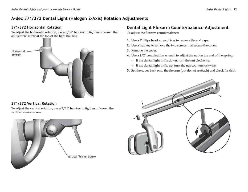
dec 371/372 Dental Light (Halogen 2-Axis) Rotation Adjustments
1/372 Horizontal Rotation adjust the horizontal rotation, use a 5/32" hex key to tighten or loosen the justment screw at the top of the light housing.
1/372 Vertical Rotation adjust the vertical rotation, use a 3/16" hex key to tighten or loosen the rtical tension screw.
Dental Light Flexarm CouTo adjust the flexarm counterbalance
1. Use a Phillips head screwdriver to2. Use a hex key to remove the two s3. Remove the cover.4. Use a 1/2" combination wrench to
○ If the dental light drifts down,○ If the dental light drifts up, tur
5. Set the cover back onto the flexarm
rizontal nsion
Vertical Tension Screw
86 A-dec Dental Lights 23
DTh
A5
A(
nents, page 36
A(
e 46
.0326.00 Rev B
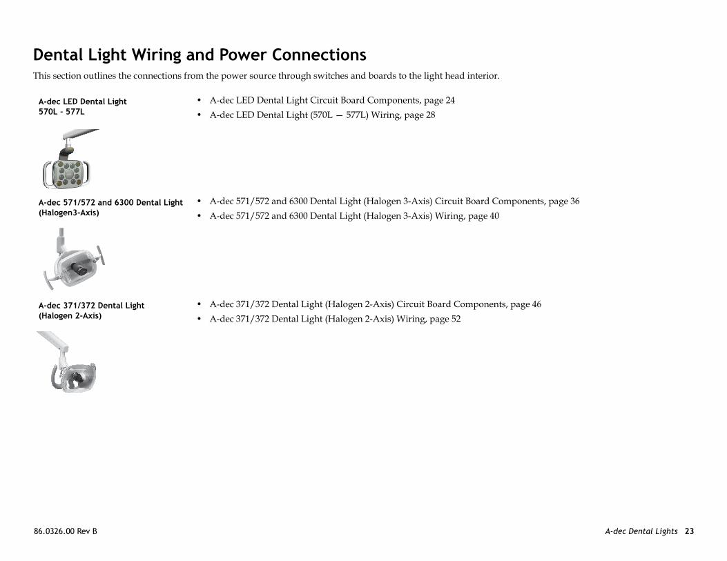
ental Light Wiring and Power Connectionsis section outlines the connections from the power source through switches and boards to the light head interior.
-dec LED Dental Light 70L - 577L
• A-dec LED Dental Light Circuit Board Components, page 24• A-dec LED Dental Light (570L — 577L) Wiring, page 28
-dec 571/572 and 6300 Dental Light Halogen3-Axis)
• A-dec 571/572 and 6300 Dental Light (Halogen 3-Axis) Circuit Board Compo• A-dec 571/572 and 6300 Dental Light (Halogen 3-Axis) Wiring, page 40
-dec 371/372 Dental LightHalogen 2-Axis)
• A-dec 371/372 Dental Light (Halogen 2-Axis) Circuit Board Components, pag• A-dec 371/372 Dental Light (Halogen 2-Axis) Wiring, page 52

A-d A-dec Dental Lights 24
A-Pa
5
6
7
8
9
4
ec Dental Lights and Monitor Mounts Service Guide
dec LED Dental Light Circuit Board Componentsrt Number: 43.0200.00 LED Driver Circuit Board
Item Description
1 J1 - 0~ terminal strip input
2 J2 - 24~ terminal strip input
3 P1 - Data port
4 P4 - LED indicator board output connector
5 DS1 - Power LED
6 DS2 - Status LED
7 DS3 - Data LED
8 J2 - LED source board terminal strip
9 P2 - Down intensity switch connector
10 P3 - Up intensity switch connector
11 P5 - On/Off switch connector
CAUTION Circuit boards are sensitive to static electricity. Electrostatic Discharge (ESD) precautions are required when touching a circuit board or making connections to or from the circuit board. Circuit boards should be installed only by an electrician or qualified service person.
1
2
10
11
3
86 A-dec Dental Lights 25
LE
LE
L
P
S
D
L tion
O ator board LEDs off: device is disconnected, r, or circuit board has failed
Cfe mode is offfe mode is onners LEDs of array board
Hde is offde is onner LEDs of array board
M mode is off mode is onner LEDs of LED array board
Lde is offde is onner LEDs of array board
.0326.00 Rev B
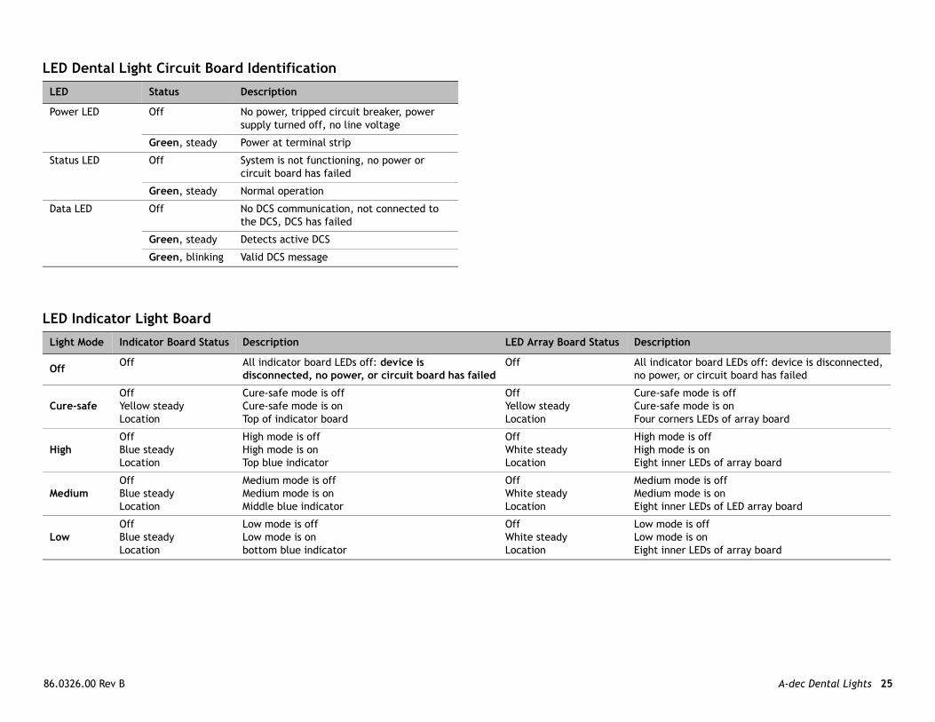
D Dental Light Circuit Board Identification
D Indicator Light Board
ED Status Description
ower LED Off No power, tripped circuit breaker, power supply turned off, no line voltage
Green, steady Power at terminal strip
tatus LED Off System is not functioning, no power or circuit board has failed
Green, steady Normal operation
ata LED Off No DCS communication, not connected to the DCS, DCS has failed
Green, steady Detects active DCS
Green, blinking Valid DCS message
ight Mode Indicator Board Status Description LED Array Board Status Descrip
ff Off All indicator board LEDs off: device is disconnected, no power, or circuit board has failed
Off All indicno powe
ure-safeOffYellow steadyLocation
Cure-safe mode is offCure-safe mode is onTop of indicator board
OffYellow steadyLocation
Cure-saCure-saFour cor
ighOffBlue steadyLocation
High mode is offHigh mode is onTop blue indicator
OffWhite steadyLocation
High moHigh moEight in
ediumOffBlue steadyLocation
Medium mode is offMedium mode is onMiddle blue indicator
OffWhite steadyLocation
MediumMediumEight in
owOffBlue steadyLocation
Low mode is offLow mode is onbottom blue indicator
OffWhite steadyLocation
Low moLow moEight in

A-d A-dec Dental Lights 26
LEPa ard
3
4
(Front)
(Back)
ec Dental Lights and Monitor Mounts Service Guide
D Dental Light Indicator Light Circuit Boardrt Number: 43.0217.00 LED Indicator Light Circuit Bo
Item Description
1 P1 - Indicator board input connector
2 DS1 and DS2 - Cure-safe mode
3 DS3 and DS4 - High mode LEDs
4 DS5 and DS6 - Medium mode LEDs
5 DS7 and DS8 - Low mode LEDs
CAUTION Circuit boards are sensitive to static electricity. Electrostatic Discharge (ESD) precautions are required when touching a circuit board or making connections to or from the circuit board. Circuit boards should be installed only by an electrician or qualified service person.
5
2
3
4
1
NOTE Electrical junction box wiring must be installed by a licensed electrician and installed according to local building codes.
86 A-dec Dental Lights 27
LEPa
r Board
.0326.00 Rev B
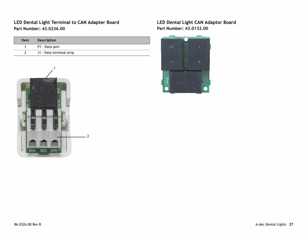
D Dental Light Terminal to CAN Adapter Boardrt Number: 43.0236.00
LED Dental Light CAN AdaptoPart Number: 43.0132.00
Item Description
1 P1 - Data port
2 J1 - Data terminal strip
1
2

A-d A-dec Dental Lights 28
A-
57
ec Dental Lights and Monitor Mounts Service Guide
dec LED Dental Light (570L — 577L) Wiring
1L on an A-dec 511 Chair
LED Indicator Light Circuit Board
86 A-dec Dental Lights 29
57
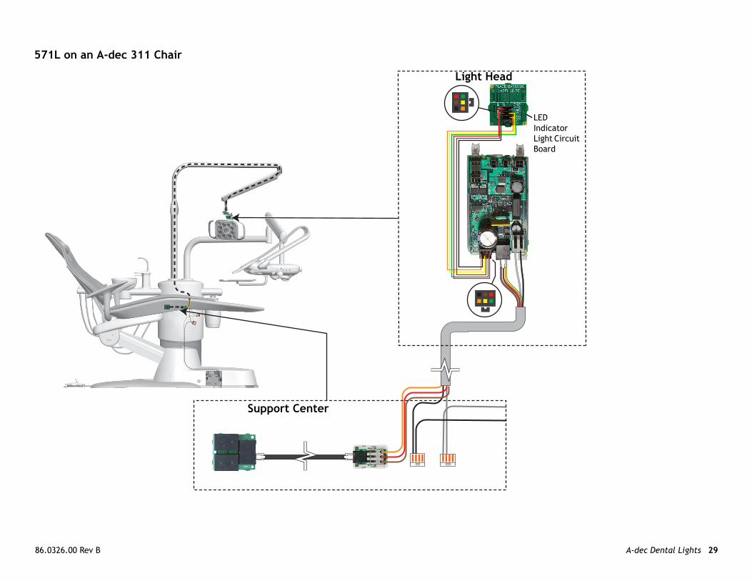
D dicator ght Circuit ard
.0326.00 Rev B
1L on an A-dec 311 Chair
Light Head
Support Center
LEInLiBo

A-d A-dec Dental Lights 30
57
ec Dental Lights and Monitor Mounts Service Guide
2L on an A-dec 511 Chair, Radius Arm Mounted
LED Indicator Light Circuit Board

86 A-dec Dental Lights 31
57
.0326.00 Rev B
4L Cabinet Mounted
LED Indicator Light Circuit Board
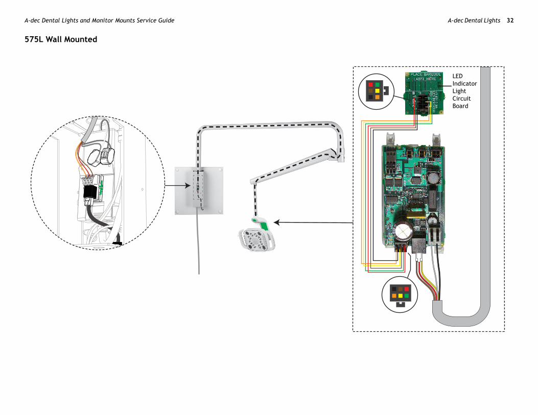
A-d A-dec Dental Lights 32
57
LED Indicator Light Circuit Board
ec Dental Lights and Monitor Mounts Service Guide
5L Wall Mounted

86 A-dec Dental Lights 33
57
LEInLiCBo
.0326.00 Rev B
6L Ceiling Mounted
D dicator ght ircuit ard
A-d A-dec Dental Lights 34
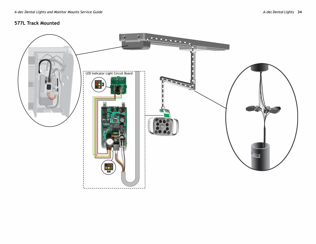
57
ec Dental Lights and Monitor Mounts Service Guide
7L Track Mounted
LED Indicator Light Circuit Board

86 A-dec Dental Lights 35
.0326.00 Rev B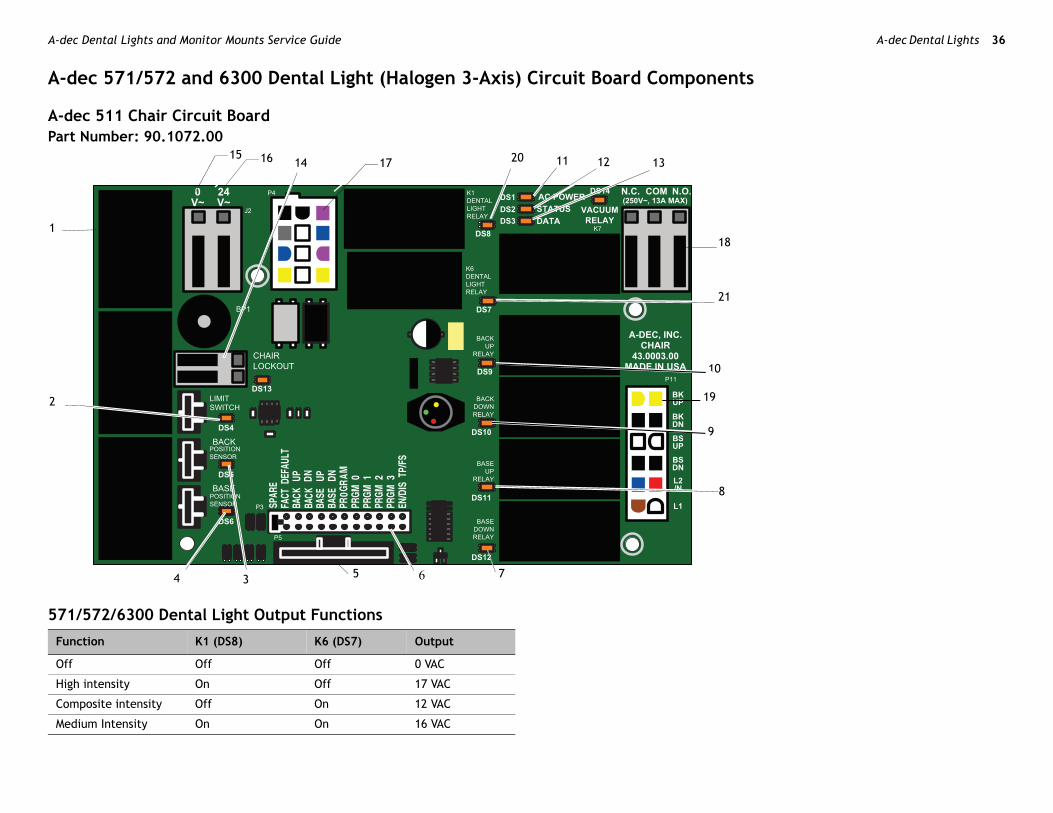
A-d A-dec Dental Lights 36
A-
A-Pa
57
1
2
F
O
H
C
M
ec Dental Lights and Monitor Mounts Service Guide
dec 571/572 and 6300 Dental Light (Halogen 3-Axis) Circuit Board Components
dec 511 Chair Circuit Boardrt Number: 90.1072.00
1/572/6300 Dental Light Output Functions
11 12 1314
4 3 5 6 7
8
10
21
18
161517 20
19
9
unction K1 (DS8) K6 (DS7) Output
ff Off Off 0 VAC
igh intensity On Off 17 VAC
omposite intensity Off On 12 VAC
edium Intensity On On 16 VAC

86 A-dec Dental Lights 37
51 on
L
D
D
D
D
D
Dp
D-
Dr
DL
s
it switch) and P10 connector
LED and P1 connector
LED and P2 connector
relay K5
lay K4
relay K3
y K2
nd terminal strip J1
output)
(output)
al light connector
ut terminal strip
enoid connector
y and K1
y and K6
sensitive to static electricity. Electrostatic are required when touching a circuit to or from the circuit board. Circuit ly by an electrician or qualified
.0326.00 Rev B
1 Chair Circuit Board Components 511 Circuit Board Identificati
ED Status Description
S1 - AC power LED Off No 24 VAC power, tripped circuit breaker, power supply turned off, no line voltage
Green, steady
24 VAC at the terminal strip
S2 - Status LED Off System is not functioning, no power or circuit board has failed
Green, steady
Normal operation
S3 - Data LED Off No DCS communication, not connected to the DCS, or DCS has failed
Green, steady
Detects active DCS
Green, blinking
Valid DCS message
S4 - Chair limit switch Off Closed, (normal)
Red Open, (activated)
S13 - Chair lockout Off Open, (normal)
Red Closed, (activated)
S5 + DS6 - Chair otentiometers
Off Potentiometer: Not connected or bad connection; moving in wrong direction; limited range of motion; or cable is not on wheel.
Yellow, steady
Normal operation
Yellow, fast blink
Upper end of travel
S9, DS10, DS11, DS12 Chair relay LEDs
Off Relay is off
On Relay is on
S7, DS8 - Dental light elay LEDs
Off Relay is off
On Relay is on
S14 - Vacuum relay ED
Off Relay is off
On Relay is on
Item Description
1 P7, P8, P9 - Data line port
2 DS4 - Stop switch LED (lim
3 DS5 - Back potentiometer
4 DS6 - Base potentiometer
5 P5 - Footswitch connector
6 P3 - Test points
7 DS12 - Base down LED and
8 DS11 - Base up LED and re
9 DS10 - Back down LED and
10 DS9 - Back up LED and rela
11 DS1 - AC power LED
12 DS2 - Status LED
13 DS3 - Data LED
14 DS13 - Chair lockout LED a
15 J2 - Ø VAC terminal strip (
16 J2 - 24 VAC terminal strip
17 P4 - Input power and dent
18 J3 - Vacuum relay K7 outp
19 P11 - Pump motor and sol
20 DS8 - Dental light LED rela
21 DS7 - Dental light LED rela
CAUTION Circuit boards areDischarge (ESD) precautionsboard or making connectionsboards should be installed onservice person.
A-d A-dec Dental Lights 38
A-Pa
63
F
O
H
C
M
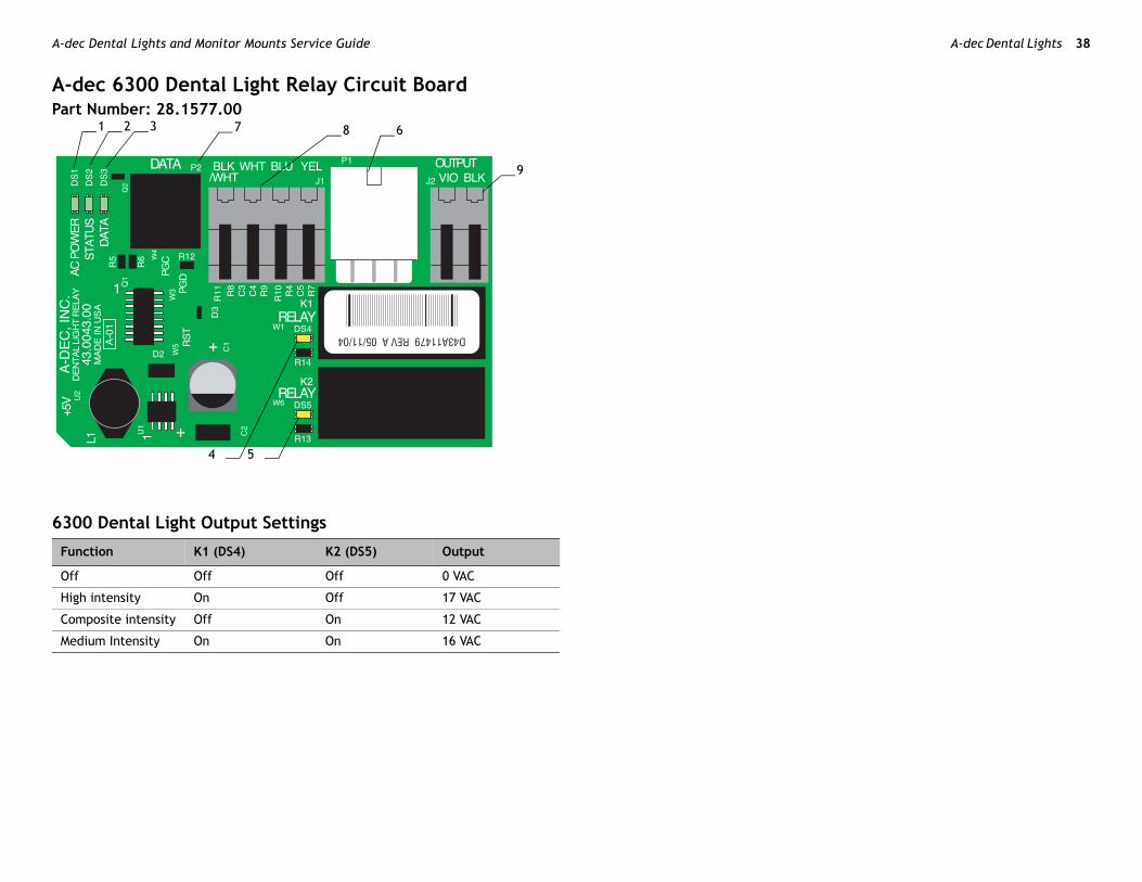
ec Dental Lights and Monitor Mounts Service Guide
dec 6300 Dental Light Relay Circuit Boardrt Number: 28.1577.00
00 Dental Light Output Settings
unction K1 (DS4) K2 (DS5) Output
ff Off Off 0 VAC
igh intensity On Off 17 VAC
omposite intensity Off On 12 VAC
edium Intensity On On 16 VAC
68
9
7321
4 5

86 A-dec Dental Lights 39
63 it Board Identification
L
DL
D
D
Dli
er
sensitive to static electricity. Electrostatic are required when touching a circuit to or from the circuit board. Circuit ly by an electrician or qualified
.0326.00 Rev B
00 Dental Light Relay Circuit Board LED Identification 6300 Dental Light Relay Circu
ED Status Description
S1 - AC power ED
Off No 24 VAC power, tripped circuit breaker, power supply turned off, no line voltage
Green, steady 24 VAC at the terminal strip
S2 - Status LED Off System is not functioning, no power or circuit board has failed
Green, steady Normal operation
S3 - Data LED Off No DCS communication, not connected to the DCS, or DCS has failed
Green, steady Detects active DCS
Green, blinking Valid DCS message
S4, DS5 - Dental ght relay LEDs
DS4, DS5
Off, Off Dental light off
On, Off High intensity
Off, On Composite intensity
On, On Medium intensity
Item Description
1 DS1 - AC power LED
2 DS2 - Status LED
3 DS3 - Data LED
4 DS4 - Dental light relay
5 DS5 - Dental light relay
6 P1 - Input power
7 P2 - Data line port
8 J1 - Toggle switch inputs
9 J2 - Dental light output pow
CAUTION Circuit boards areDischarge (ESD) precautionsboard or making connectionsboards should be installed onservice person.

A-d A-dec Dental Lights 40
A-
63
ec Dental Lights and Monitor Mounts Service Guide
dec 571/572 and 6300 Dental Light (Halogen 3-Axis) Wiring
00 Ceiling, Wall, and Preference Mount Switch and Data Line Connections
6300 Dental Light Circuit Board
Switch and BulbConnections

86 A-dec Dental Lights 41
63
6
.0326.00 Rev B
00 Track Light Switch Connections and Data Line (2004 and Later)
To Chair Circuit Board
300 Light Circuit Board
Switch and BulbConnections

A-d A-dec Dental Lights 42
63
ec Dental Lights and Monitor Mounts Service Guide
00 Track Light Switch Connections and Data Line (2003 and Earlier)
6300 Light Circuit Board
To Chair Circuit Board

86 A-dec Dental Lights 43
A-Pa
Po
are 5 VDC, then the output voltage on
.0326.00 Rev B
dec 571/572 and 6300 Dental Light Power Cablesrt Number: 28.1584.00
wer Cable
Pin Voltage Wire
1 0 VDC (circuit ground) Black/white
2 0 VAC Black
3 5 VDC = high or medium0 VDC = composite
Yellow (composite)
4 5 VDC = medium or composite0 VDC = high out
Blue(high)
5 17/16/12.1 VAC Violet
6 5 VDC = on/off toggle = open0 VDC = on/off toggle = closed
White(on/off)
NOTE When Pin 3 and Pin 4Pin 5 is medium intensity.
A-d A-dec Dental Lights 44
A-Pa
Th
10 ing
ec Dental Lights and Monitor Mounts Service Guide
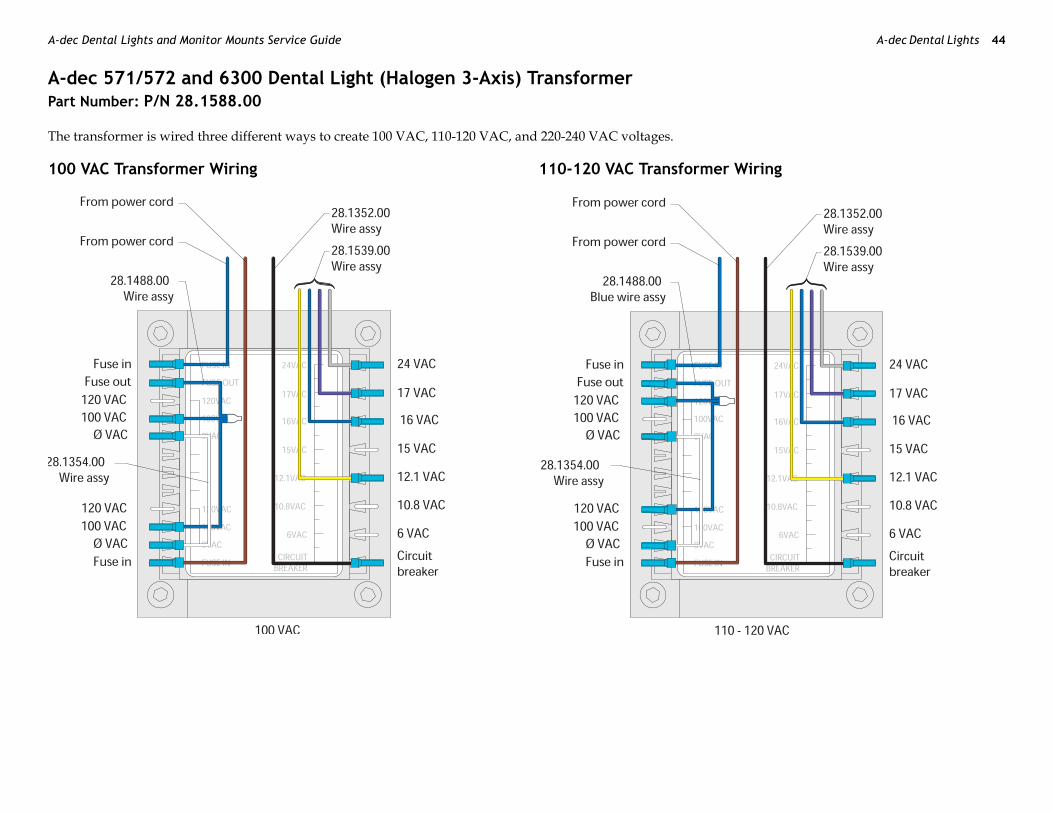
dec 571/572 and 6300 Dental Light (Halogen 3-Axis) Transformer rt Number: P/N 28.1588.00
e transformer is wired three different ways to create 100 VAC, 110-120 VAC, and 220-240 VAC voltages.
0 VAC Transformer Wiring 110-120 VAC Transformer Wir

86 A-dec Dental Lights 45
22
.0326.00 Rev B
0-240 VAC Transformer Wiring

A-d A-dec Dental Lights 46
A-
A-
30
20
Dental Light Output Settings
K1 (DS8) K6 (DS7) Output
Off Off 0 VAC
sity On Off 17 VAC
intensity Off On 12 VAC
ec Dental Lights and Monitor Mounts Service Guide
dec 371/372 Dental Light (Halogen 2-Axis) Circuit Board Components
dec 311 Dental Chair Circuit Board for 371/372 Dental Light on an A-dec 311 Chair
1
16 4 5 18 24 25 13 14 2627
19
17
28
29
6
722
23
2
21
11
3
812
9
15
10 371/372
Function
Off
High inten
Composite
86 A-dec Dental Lights 47
31 ification
L
DDL
DS
D
D
Dp
DDr
Dli
Item Description
16 P3 - testpoints header
17 P4 - input power connector
18 P5 - touchpad or footswitch connector
19 P6/P7 - data ports
20 P8 - back motor connector
21 P9 - input power connector
22 P11 - base motor connector
23 P12 - input power connector
24 J1 - Ø VAC terminal strip (output) for assistant’s, doctor’s, floor box
25 J2 - 24 VAC terminal strip (output) for assistant’s, doctor’s and floor box
26 J3 - 0 VAC terminal strip (output) for support center
27 J3 - 24 VAC terminal strip (output) for support center
28 J5 - dental light output terminal strip
29 J6 - dental light input terminal strip
30 J7 - base solenoid terminal strip
sensitive to static electricity. Electrostatic are required when touching a circuit to or from the circuit board. Circuit ly by an electrician or qualified
.0326.00 Rev B
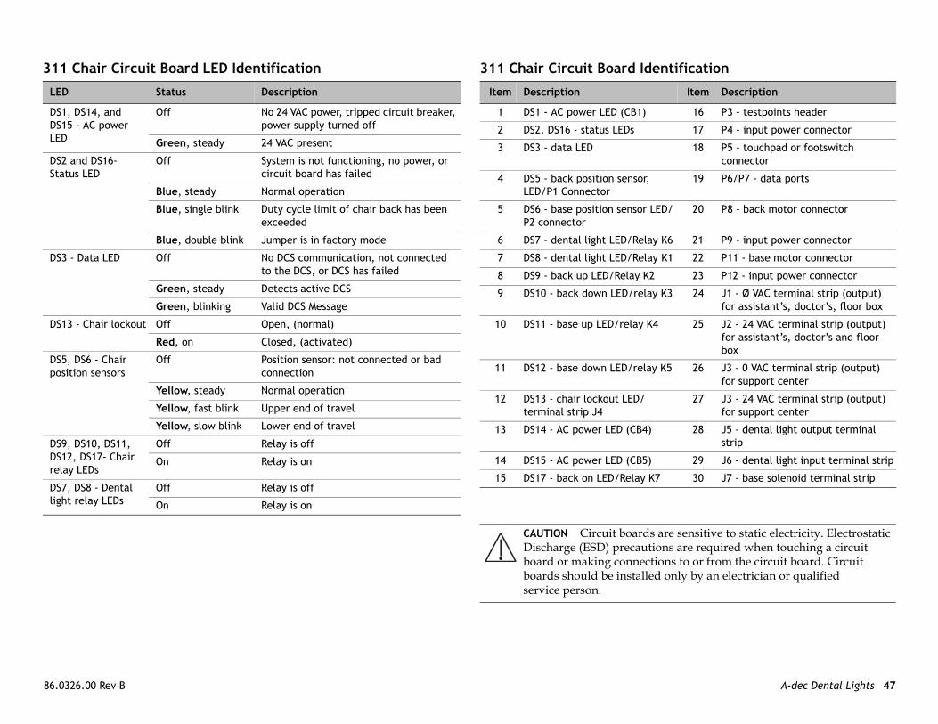
1 Chair Circuit Board LED Identification 311 Chair Circuit Board Ident
ED Status Description
S1, DS14, and S15 - AC power ED
Off No 24 VAC power, tripped circuit breaker, power supply turned off
Green, steady 24 VAC present
S2 and DS16- tatus LED
Off System is not functioning, no power, or circuit board has failed
Blue, steady Normal operation
Blue, single blink Duty cycle limit of chair back has been exceeded
Blue, double blink Jumper is in factory mode
S3 - Data LED Off No DCS communication, not connected to the DCS, or DCS has failed
Green, steady Detects active DCS
Green, blinking Valid DCS Message
S13 - Chair lockout Off Open, (normal)
Red, on Closed, (activated)
S5, DS6 - Chair osition sensors
Off Position sensor: not connected or bad connection
Yellow, steady Normal operation
Yellow, fast blink Upper end of travel
Yellow, slow blink Lower end of travel
S9, DS10, DS11, S12, DS17- Chair elay LEDs
Off Relay is off
On Relay is on
S7, DS8 - Dental ght relay LEDs
Off Relay is off
On Relay is on
Item Description
1 DS1 - AC power LED (CB1)
2 DS2, DS16 - status LEDs
3 DS3 - data LED
4 DS5 - back position sensor, LED/P1 Connector
5 DS6 - base position sensor LED/P2 connector
6 DS7 - dental light LED/Relay K6
7 DS8 - dental light LED/Relay K1
8 DS9 - back up LED/Relay K2
9 DS10 - back down LED/relay K3
10 DS11 - base up LED/relay K4
11 DS12 - base down LED/relay K5
12 DS13 - chair lockout LED/terminal strip J4
13 DS14 - AC power LED (CB4)
14 DS15 - AC power LED (CB5)
15 DS17 - back on LED/Relay K7
CAUTION Circuit boards areDischarge (ESD) precautionsboard or making connectionsboards should be installed onservice person.

A-d A-dec Dental Lights 48
A-
37
1
2
F
O
H
C
ec Dental Lights and Monitor Mounts Service Guide
dec 511 Chair Board Components for 371/372 Dental Light on an A-dec 511 Chair
1/372 Dental Light Output Settings
11 12 1314
4 3 5 6 7
8
10
21
18
1615 17
20
19
9
unction K1 (DS8) K6 (DS7) Output
ff Off Off 0 VAC
igh intensity On Off 17 VAC
omposite intensity Off On 12 VAC

86 A-dec Dental Lights 49
51 ification
L
DL
D
D
Ds
Dlo
DCp
DDC
DDr
Dr
Item Description
11 DS1 - AC power LED
12 DS2 - status LED
13 DS3 - data LED
14 DS13 - chair lockout LED/terminal strip J1
15 J2 - 0 VAC terminal strip (output)
16 J2 - 24 VAC terminal strip (output)
17 P4 - Input power/dental light connector
18 J3 - vacuum relay K7 output terminal strip
19 P11 - pump motor/solenoid connector
20 DS8 - dental light LED relay/K1
21 DS7 - dental light LED relay/K6
sensitive to static electricity. Electrostatic are required when touching a circuit to or from the circuit board. Circuit ly by an electrician or qualified
.0326.00 Rev B
1 Chair Circuit Board LED Identification 511 Chair Circuit Board Ident
ED Status Description
S1 - AC power ED
Off No 24 VAC power, tripped circuit breaker, power supply turned off, no line voltage
Green, steady 24 VAC at the terminal strip
S2 - Status LED Off System is not functioning, no power or circuit board has failed
Green, steady Normal operation
S3 - Data LED Off No DCS communication, not connected to the DCS, or DCS has failed
Green, steady Detects active DCS
Green, blinking Valid DCS message
S4 - Chair limit witch
Off Closed, (normal)
Red Open, (activated)
S13 - Chair ckout
Off Open, (normal)
Red Closed, (activated)
S5 + DS6 - hair otentiometers
Off Potentiometer: Not connected or bad connection; moving in wrong direction; limited range of motion; or cable is not on wheel
Yellow, steady Normal operation
Yellow, fast blink Upper end of travel
S9, DS10, S11, DS12 - hair relay LEDs
Off Relay is off
On Relay is on
S7, DS8 - ental light elay LEDs
Off Relay is off
On Relay is on
S14 - Vacuum elay LED
Off Relay is off
On Relay is on
Item Description
1 P7, P8, P9 - data ports
2 DS4 - stop switch LED (limit switch)/P10 connector
3 DS5 - back potentiometer LED/P1 connector
4 DS6 - base potentiometer LED/P2 connector
5 P5 - footswitch connector
6 P3 - testpoints header
7 DS12 - base down LED/relay K5
8 DS11 - base up LED/relay K4
9 DS10 - back down LED/relay K3
10 DS9 - back up LED/relay K2
CAUTION Circuit boards areDischarge (ESD) precautionsboard or making connectionsboards should be installed onservice person.

A-d A-dec Dental Lights 50
A-
37
F
O
H
C
ec Dental Lights and Monitor Mounts Service Guide
dec 371/372 Dental Light Relay Circuit Board
1/372 Dental Output Settings
68
9
7321
4 5
unction K1 (DS4) K2 (DS5) Output
ff Off Off 0 VAC
igh intensity On Off 17 VAC
omposite intensity Off On 12 VAC

86 A-dec Dental Lights 51
37 ircuit Board Identification
L
DL
D
D
DDr
er
sensitive to static electricity. Electrostatic are required when touching a circuit to or from the circuit board. Circuit ly by an electrician or qualified
.0326.00 Rev B
1/372 Dental Light Relay Board LED Identification 371/372 Dental Light Relay C
ED Status Description
S1 - AC power ED
Off No 24 VAC power, tripped circuit breaker, power supply turned off, no line voltage
Green, steady 24 VAC at the terminal strip
S2 - Status LED Off System is not functioning, no power or circuit board has failed
Green, steady Normal operation
S3 - Data LED Off No DCS communication, not connected to the DCS, or DCS has failed
Green, steady Detects active DCS
Green, blinking Valid DCS message
S4, DS5 - ental light elay LEDs
DS4, DS5
Off, Off Dental light off
On, Off High intensity
Off, On Composite intensity
On, On Medium intensity
Item Description
1 DS1 - AC power LED
2 DS2 - Status LED
3 DS3 - Data LED
4 DS4 - Dental light relay
5 DS5 - Dental light relay
6 P1 - Input power
7 P2 - Data port
8 J1 - Toggle switch inputs
9 J2 - Dental light output pow
CAUTION Circuit boards areDischarge (ESD) precautionsboard or making connectionsboards should be installed onservice person.

A-d A-dec Dental Lights 52
A-
37
OnThlig
Connections
P
O
C
11)
ec Dental Lights and Monitor Mounts Service Guide
dec 371/372 Dental Light (Halogen 2-Axis) Wiring
1/372 Dental Light Connections
/Off Switche on/off switch is used to manually turn on or off the dental light from the ht head. The replacement kit is p/n 90.1039.00.
371/372 Dental Light Switch
TIP Any DCS enabled touchpad connected to a light’s DCS system will activate the dental light function.
osition Voltage Wire
pen 5 VDC White
losed 0 VDC White
NOTE All DC voltage measurements are taken with the black multimeter lead on the black/white wire.
371/372 Light (Before September 2011)
371/372 Lights (Effective September 20
86 A-dec Dental Lights 53
A-
T
J
J
.0326.00 Rev B
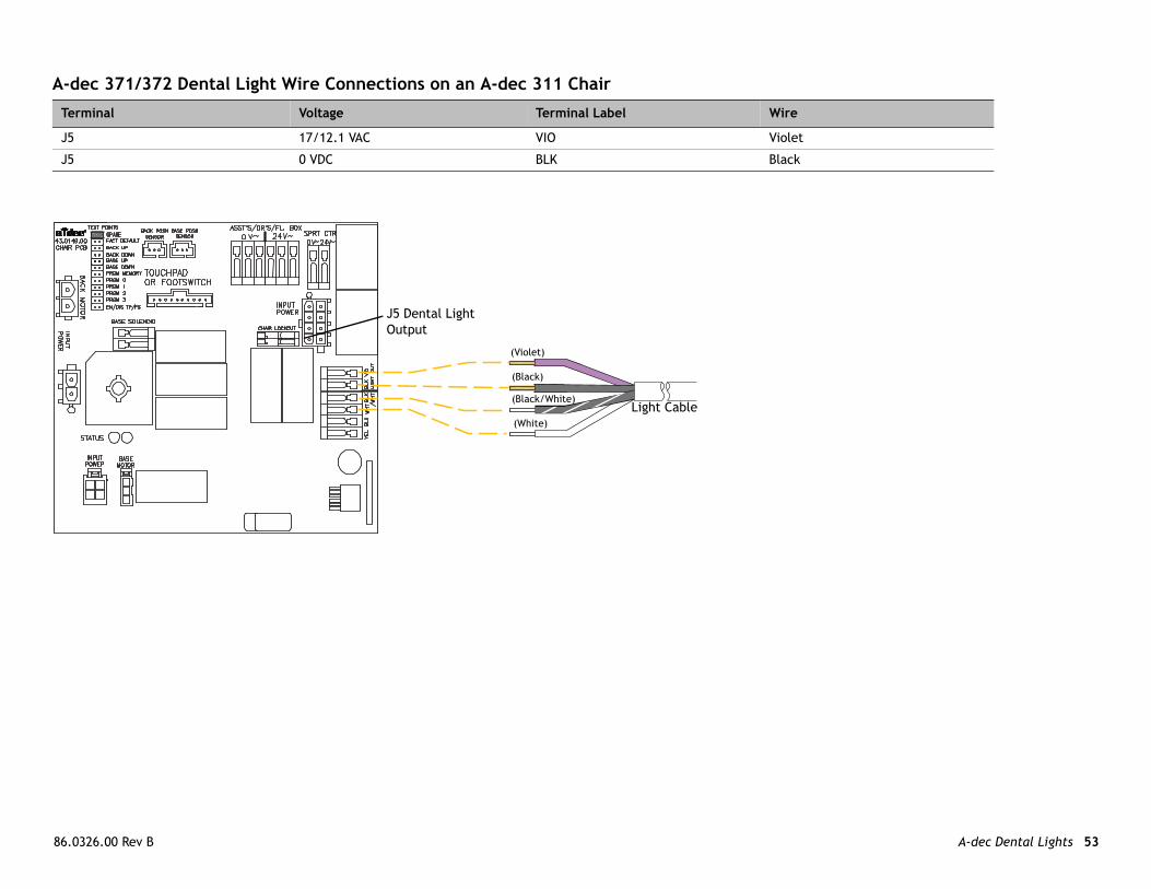
dec 371/372 Dental Light Wire Connections on an A-dec 311 Chair
erminal Voltage Terminal Label Wire
5 17/12.1 VAC VIO Violet
5 0 VDC BLK Black
Light Cable
J5 Dental Light Output
(Violet)
(Black/White)
(Black)
(White)
A-d A-dec Dental Lights 54
A-
P Wire
5 Violet
2 Black
6 White
1 Black with white stripe
Light Cable
ec Dental Lights and Monitor Mounts Service Guide
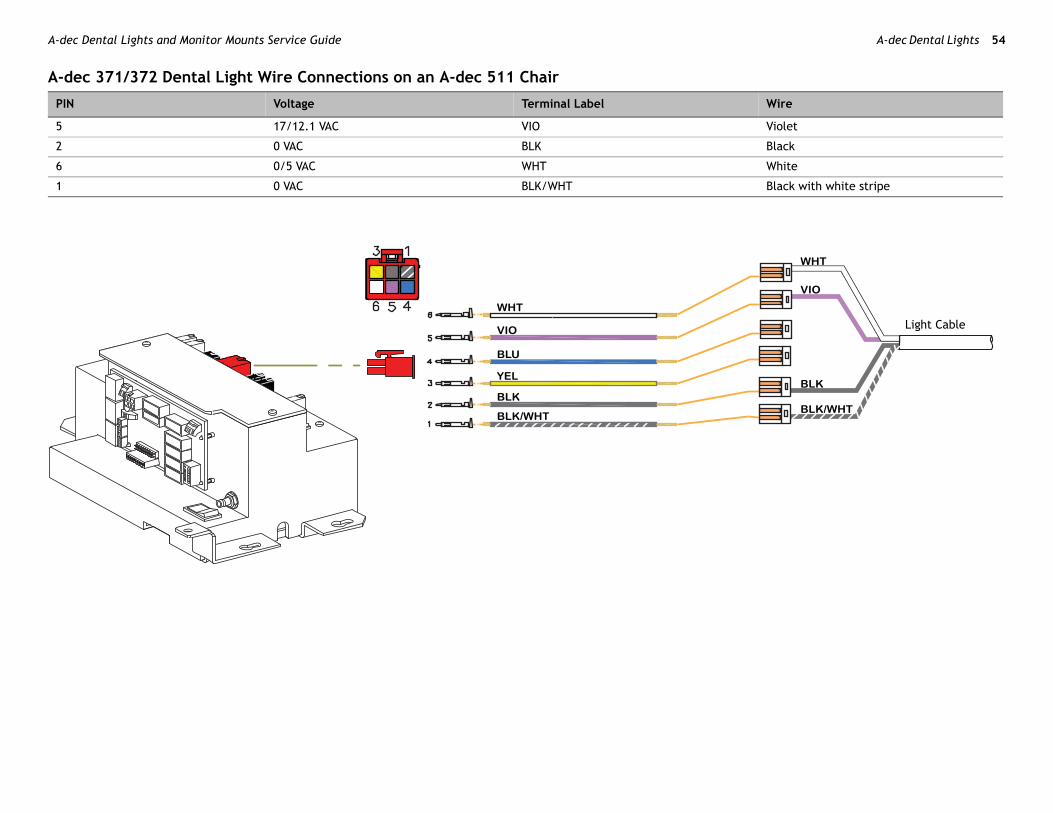
dec 371/372 Dental Light Wire Connections on an A-dec 511 Chair
IN Voltage Terminal Label
17/12.1 VAC VIO
0 VAC BLK
0/5 VAC WHT
0 VAC BLK/WHT
86 A-dec Dental Lights 55
A-
T Wire
J Violet
J Black
3
J Black/White
J White (On/Off)
J Blue
J Yellow (composite)
J Violet
J Black
Light Cable
PoIn
upport Center ata Line
30
tion correctly.
.0326.00 Rev B
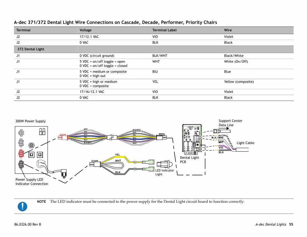
dec 371/372 Dental LIght Wire Connections on Cascade, Decade, Performer, Priority Chairs
erminal Voltage Terminal Label
2 17/12.1 VAC VIO
2 0 VAC BLK
72 Dental LIght
1 0 VDC (circuit ground) BLK/WHT
1 5 VDC = on/off toggle = open0 VDC = on/off toggle = closed
WHT
1 5 VDC = medium or composite0 VDC = high out
BlU
1 5 VDC = high or medium0 VDC = composite
YEL
2 17/16/12.1 VAC VIO
2 0 VAC BLK
wer Supply LED dicator Connection
SD
0W Power Supply
Dental Light PCB
372
LED IndicatorLight
NOTE The LED indicator must be connected to the power supply for the Dental Light circuit board to func

A-d A-dec Dental Lights 56
DTh ot intended to cover every situation, but inc
Ta
P
Lcc
bulb.
gain, disconnect P4, J5, and J6 on the 311 upply.aker now trips, replace the 311 chair circuit
6 (if any). If the circuit breaker now trips,
5. If the circuit breaker trips, replace the
light connector at the power supply and reset nnect the dental light to the power supply, if iring.
pped:
reset the circuit breaker.
nnect the dental light to the power supply.) ss, switch wiring, dental light circuit board, ne at a time to determine the location of the
light and reset the circuit breaker. If CB5 he power supply and if CB5 trips, the dental
he breaker is tripped, disconnect the dental the breaker trips again, reset the circuit a switch is faulty.
Ltt
nd H6 on the circuit board.
ec Dental Lights and Monitor Mounts Service Guide
ental Light Troubleshootingis table contains tips and troubleshooting information to assist you in diagnosing dental light problems. This table is nludes the most common problems that you may encounter.
ble 1. LED (570L - 577L), 371, 372, 571, 572, 6300 Troubleshooting
roblem Possible Cause Description
ight does not work (light onnected to 311 chair ircuit board).
The bulb has failed (non-LED dental lights).
Check for voltage at the bulb socket, if voltage is present, replace the
Check the color of the bulb, replace if discolored.
The dental light circuit breaker, CB6, has been tripped or the power supply has failed.
• Check the circuit breaker and reset it. If the circuit breaker trips achair board. If the circuit breaker trips again, replace the power s
• If the circuit breaker does not trip, reconnect P4. If the circuit breboard.
• If the circuit breaker does not trip, reconnect the connections to Jreplace the switch wiring to the 571-300 dental light.
• If the circuit breaker does not trip, reconnect the connections to Jdental light.
371 or 372 Dental Lights on a 511 chair:• If CB5 on the 300W power supply is tripped, disconnect the dental
the circuit breaker. If CB5 trips again, replace the power supply. CoCB5 trips, replace the dental wiring harness or the adapter cable w
371 or 372 Dental Lights NOT on a 511 or 311 chair:• If the dental light circuit breaker on the 300 W power supply is tri
- Disconnect the dental light connector at the power supply and
- If the circuit breaker trips again, replace the power supply. (CoIf the circuit breaker trips, either the dental light wiring harneor dental light circuit board power cable has failed. Connect ofailure.
571 Dental Lights: • If CB5 on the 300W power supply is tripped, disconnect the dental
trips gain, replace the power supply. Connect the dental light to tlight wiring harness or a switch is faulty.
572 Dental Lights: • The dental light circuit breaker is near the power transformer. If t
light wiring harness from the transformer and reset the breaker. Ifbreaker. If the breaker does not trip, the dental wiring harness or
The bulb socket is faulty (non-LED dental lights).
Replace the socket.
ight works from the ouchpad(s) but not from he dental light switches.
Loose connection in the dental light wiring harness.
Verify that the wiring is connected properly.
Check the connections at the dental light switches and terminals H5 a

86 A-dec Dental Lights 57
Lli
he circuit board, if the light works from the
Ld
F
T
Tbe
he routing of the cable, replace the cable
Lind
ion. Replace or clean as necessary.
VAC
Up ry.
P
e shield and reflector. Refer to the
n the composite position results in
.0326.00 Rev B
ight works from the dental ght switches.
Faulty data line from the touchpad to the circuit board.
Temporarily substitute a known good data line from the touchpad to ttouchpad, determine and replace any bad bypassed data lines.
ight head is loose or ifficult to position.
Rotation tension screws are too loose or tight.
Adjust the appropriate axis tension.
lexarm drifts. Tension adjustment nut inside the flexarm is too loose or tight.
Adjust the flexarm counterbalance.
rack light trolley drifts. Track is not level. Use wedges to level the track light ceiling pallet (P/N 017.017.00).
rack trolley light bounces ack when pushed to the nd of the track.
Power cable is hanging up inside the track.
Check power cable in track for proper routing. If you cannot correct tassembly.
ight intensity is dim, consistent, or the color is istorted.
Reflector or light shield may be damaged (non-LED dental light).
Inspect the dental light shield and reflector for damage or contaminat
For the 372 Dental Light, the intensity switch is in the medium or composite position.
Check the intensity switch position.
The mains voltage is low. Verify the mains voltage is within specifications: 100/110-120/220-240
nsatisfactory light attern.
Light is out of focus, reflector or light shield may be damaged (non-LED dental lights).
1. Focus the light.
2. Check the light shield for severe abrasions, and replace if necessa
3. Clean the reflector and light shield.
roblem Possible Cause Description
CAUTION Abrasives, disinfectants or chlorine damage thInstructions for Use for cleaning instructions.
NOTE Turning the light on when the intensity switch is imedium intensity.

A-d A-dec Dental Lights 58
ec Dental Lights and Monitor Mounts Service Guide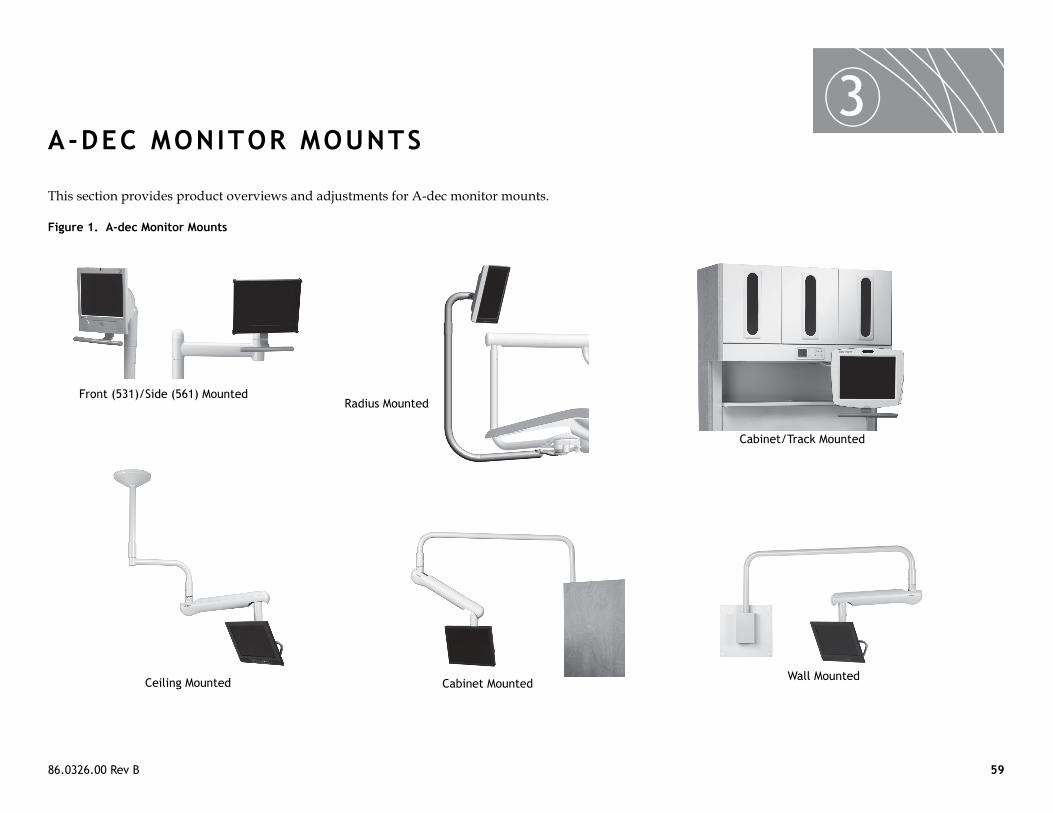
86.0326.00 Re 59
3A-DE
This section
Figure 1. A-d
inet/Track Mounted
Front (5
Wall Mounted
v B
C MONITOR MOUNTS
provides product overviews and adjustments for A-dec monitor mounts.
ec Monitor Mounts
Cab
31)/Side (561) Mounted
Cabinet MountedCeiling Mounted
Radius Mounted

A-d A-dec Monitor Mounts 60
M
MM
R
M
ec Dental Lights and Monitor Mounts Service Guide
onitor Mount Overview
onitor Mount Specificationaximum Weight 31 lb (14.1 kg) for chair- and cabinet track-mount
20 lb (9.1 kg) for ceiling, Central Console, and wall-mount
ecommended Maximum Size 19 " flat-panel LCD
ounting Compliance 75 mm and 100 mm VESA mounting compliant
NOTE A line voltage power cord is provided with the monitor mount.
NOTE Specifications are subject to change without notice. Some requirements may vary from country to country. For more information, contact your authorized A-dec dealer.

86 A-dec Monitor Mounts 61
M
Fr
TiTolocup
DrTolocdo
drift movement to the monitor. Use the d drift.
DrAd
Track Mount
Radius and Support Mount (561, 531, Track/Cabinet)
Clutch Assembly
.0326.00 Rev B
onitor Mount Adjustments (Clutch)
iction Adjustment
lt Friction adjust the tilt friction, tighten or loosen the tilt friction adjustment screw ated on the top of the monitor mount. Tilt is the angling of the monitor wards.
ift Friction adjust the drift friction, tighten or loosen the drift friction adjustment screw ated on the top of the monitor mount. Drift is the movement of the monitor wnward.
Clutch Assembly The clutch assembly provides tilt andadjustment screws to adjust the tilt an
NOTE For any adjustment to work properly, the center bolt must be tightened.
Tilt (Upward) Friction Adjustment Screw
ift (Downward) Friction justment Screw
Center Bolt
Bumper
Hub
Hub
Adjustment Screws
Adjustment Screws
Clutch Assembly

A-d A-dec Monitor Mounts 62
TrThtra
1.
2.
ent (Track Mount)en the panning friction adjustment screw tes.
TraHu
Adjusts ntal Rotation
ec Dental Lights and Monitor Mounts Service Guide
ay Holder Tension Adjustment (Support Side, Model 561)e tension adjustment screw for the tray holder is located in the hub of the y holder arm.
Locate the small hole in the tray holder hub, and insert a 5/32" hex key through the hole.Rotate the tray support arm to adjust the tension (right to increase tension, left to decrease tension).
Panning Friction AdjustmUse a 3/16" hex key to tighten or looson the track mount until it freely rota
5/32" Hex KeyHole
y Holder b
ScrewHorizo

86 A-dec Monitor Mounts 63
MTiThmoto
HoAd
ent
Horizontal Tension Screw
.0326.00 Rev B
onitor Mount Adjustments (Handle)lt Adjustmente monitor mount includes a tilt adjustment handle. While holding the nitor, turn the handle to the left and position the monitor. Turn the handle
the right to lock the tilt in position.
rizontal Pivotjust the horizontal pivot behind the monitor using a 5/16" hex key.
Monitor Adjustments
Tilt AdjustmHandle
A-d A-dec Monitor Mounts 64
ec Dental Lights and Monitor Mounts Service Guide

86.0326.00 Rev BCopyright 2012 A-dec Inc.
All rights reserved.
A-dec Headquarters2601 Crestview DriveNewberg, OR 97132 USATel: 1.800.547.1883 Within USA/CanadaTel: 1.503.538.7478 Outside USA/CanadaFax:1.503.538.0276www.a-dec.com
International Distribution Centers
A-dec United KingdomEU Authorized RepresentativeAustin House, 11 Liberty WayNuneaton, Warwickshire CV11 6RZEngland Tel: 0800 ADECUK (233285) Within UKTel: +44 (0) 24 7635 0901 Outside UKwww.a-dec.co.uk
A-dec AustraliaUnit 85-9 Ricketty StreetMascot, NSW 2020AustraliaTel: 1.800.225.010 Within AustraliaTel: +61 (0)2 8332 4000 Outside Australiawww.a-dec.com.au
ÍvÈ.Ç#:È.00XÎ