Embed Size (px)
DESCRIPTION
A-dec 511 Dental Chair. Product Overview – Pg 10. A-dec 511 Chair Features Headrest Armrest Baseplate Back Seat Hydraulic Motor Pump Assembly. Chair Specifications – Pg 11. Load Capacity Patient 300 lb (135 kg) Accessory 250 lb (113 kg) Note: Bolt chair to floor Power On/Off Button - PowerPoint PPT Presentation
Citation preview

1Copyright2005All Rights Reserved
A-dec 511 Dental Chair

2Copyright2005All Rights Reserved
Product Overview – Pg 10 A-dec 511 Chair
Features Headrest Armrest Baseplate Back Seat Hydraulic Motor Pump Assembly

3Copyright2005All Rights Reserved
Chair Specifications – Pg 11 Load Capacity
Patient 300 lb (135 kg) Accessory 250 lb (113 kg) Note: Bolt chair to floor
Power On/Off Button Limp-Along Feature

4Copyright2005All Rights Reserved
Chair Specifications – Pg 12 Chair Power Supply
Comes standard with the 511 chair
Electric switch connects the power supply to pilot air

5Copyright2005All Rights Reserved
Chair Flow Diagram – Pg 15

6Copyright2005All Rights Reserved
Service/Usage Information – Pg 16 Chair Covers
Motor pump cover requires hex wrench
Lift arm cover: pull outward to flex cover over stops
Stop plate cover: pull tabs out over pegs

7Copyright2005All Rights Reserved
Service/Usage Information – Pg 17 Factory Default Routine
Sets the base and back upper limits Calculates new presets base on actual range of the chair Verifies that the potentiometers work

8Copyright2005All Rights Reserved
Chair Circuit Board – Pg 18-19 Circuit Board Components
Refer to the table on page 18 and Figure 6 on page 19

9Copyright2005All Rights Reserved
Chair Circuit Board Revisions
Rev D Adds bump up when chair lockout detected Increased electrical current for lift and support arm limit switches, released
01/05
Rev E Base up/down travel limits can be set, released 04/05
Rev F Positioning improved when using button for x-ray/rinse, released 06/05

11Copyright2005All Rights Reserved
Circuit Board Components – Pg 20 LED Identification

12Copyright2005All Rights Reserved
Hydraulic System – Pg 21 How the Hydraulic System Operates
Motor-driven hydraulic pump with solenoids Hydraulic cylinders Hydraulic Fluid Reservoir
Check with base and back full up Use only A-dec fluid 61.0197.00
System holds 40 ounces 1.18 liters.

13Copyright2005All Rights Reserved
Hydraulic System Bidirectional motor
Replace as compete assembly
Depressurize the system before disassembling hydraulic components.

14Copyright2005All Rights Reserved
Hydraulic System – Pg 22 Hydraulic Cylinders
The hydraulic cylinders operate during Base Up and Back Up functions. Springs and gravity retract the piston during Base Down and Back Down functions.
The chair seat travels vertically from a low point of 13.5” (343mm) to a high point of 31.5” (800mm) above the floor.

15Copyright2005All Rights Reserved
Chair Hydraulic Base Cylinder Base cylinder replacement
Remove motor pump, lift arm and stop plate covers
Position chair base up Lower chair on solid support Remove rod screw and the pivot
pin Remove reservoir cap Operate base down while pushing
rod into cylinder Remove 2 screws at base of
cylinder Remove hydraulic hose from
cylinder

16Copyright2005All Rights Reserved
Chair Hydraulic Back Cylinder Back cylinder replacement
Remove seat and back upholstery Position chair back down Remove hydraulic hose and vent
line from cylinder Remove snap ring at rear of
trunion Unscrew cylinder rod from
bearing clevis using a 9/64 hex key through hole
Pull cylinder out from front of trunion

17Copyright2005All Rights Reserved
Hydraulic System – Pg 23 Capacitor
The capacitor is energized during chair Base Up or Back Up functions.
Voltage and F specific

18Copyright2005All Rights Reserved
Hydraulic System – Pg 24 Solenoids
Down only Line voltage specific
How to Test Solenoids To check for a failed solenoid,
test the solenoids using a volt/ohm meter or magnetic pull test.

19Copyright2005All Rights Reserved
Hydraulic System Pump Motor Assembly
Soft Start/Stop Accumulator - dampens hydraulic shock
by acting like a shock absorber. Bi-directional Pump
Turns one direction for Base Up,the opposite for Back Up
Gravity and springs only forBase Down and Back Down
Accumulator

20Copyright2005All Rights Reserved
Potentiometer – Pg 25 Back and base pots are
interchangeable assemblies P/N 90.1069.00

21Copyright2005All Rights Reserved
Chair Stop Plate – Pg 26 Activation causes chair to
stop down movement, PCB signals momentary base up

22Copyright2005All Rights Reserved
Swivel Brake – Pg 27 Swivel Brake Adjustment
Release brake tension Insert 7/64” hex wrench in through-
hole and into adjustment screw Turn wrench to right to increase
brake friction

23Copyright2005All Rights Reserved
Headrest – Pg 28 Drift Adjustment
Use 1/8” hex wrench Turn clockwise to increase
friction on glide bar
24Copyright2005All Rights Reserved
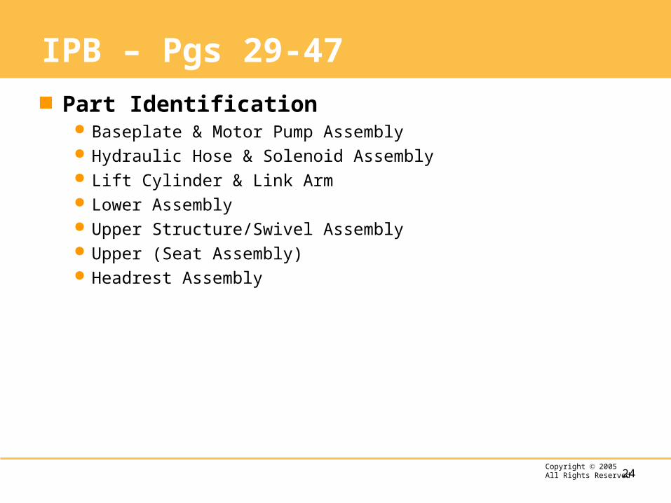
IPB – Pgs 29-47 Part Identification
Baseplate & Motor Pump Assembly Hydraulic Hose & Solenoid Assembly Lift Cylinder & Link Arm Lower Assembly Upper Structure/Swivel Assembly Upper (Seat Assembly) Headrest Assembly

25Copyright2005All Rights Reserved
A-dec 511 Dental Chair