Embed Size (px)
Citation preview
441
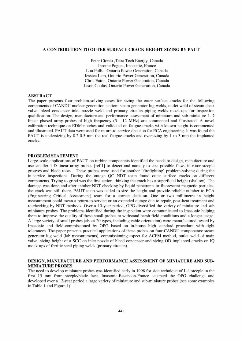
A CONTRIBUTION TO OUTER SURFACE CRACK HEIGHT SIZING BY PAUT
Peter Ciorau ,Tetra Tech Energy, Canada
Jerome Poguet, Imasonic, France
Lou Pullia, Ontario Power Generation, Canada
Jessica Lam, Ontario Power Generation, Canada
Chris Eaton, Ontario Power Generation, Canada
Jason Coulas, Ontario Power Generation, Canada
ABSTRACT
The paper presents four problem-solving cases for sizing the outer surface cracks for the following
components of CANDU nuclear generation station: steam generator lug welds, outlet weld of steam chest
valve, bleed condenser inlet nozzle weld and primary circuits piping welds mock-ups for inspection
qualification. The design, manufacture and performance assessment of miniature and sub-miniature 1-D
linear phased array probes of high frequency (5 - 12 MHz) are commented and illustrated. A novel
calibration technique on EDM notches and validated on fatigue cracks with known height is commented
and illustrated. PAUT data were used for return-to-service decision for ECA engineering. It was found the
PAUT is undersizing by 0.2-0.5 mm the real fatigue cracks and oversizing by 1 to 3 mm the implanted
cracks.
PROBLEM STATEMENT
Large-scale applications of PAUT on turbine components identified the needs to design, manufacture and
use smaller 1-D linear array probes [ref.1] to detect and namely to size possible flaws in rotor steeple
grooves and blade roots. . These probes were used for another “firefighting’ problem-solving during the
in-service inspections. During the outage QC NDT team found outer surface cracks on different
components. Trying to grind was the first action, thinking the crack has a superficial height (shallow). The
damage was done and after another NDT checking by liquid penetrants or fluorescent magnetic particles,
the crack was still there. PAUT team was called to size the height and provide reliable number to ECA
(Engineering Critical Assessment) team for a correct decision. One or two millimetre in height
measurement could mean a return-to-service or an extended outage due to repair, post-heat treatment and
re-checking by NDT methods. Over a 10-year period, OPG diversified the variety of miniature and sub
miniature probes. The problems identified during the inspection were communicated to Imasonic helping
them to improve the quality of these small probes to withstand harsh field conditions and a longer usage.
A large variety of small probes (about 20 types, including cable orientation) were manufactured, tested by
Imasonic and field-commissioned by OPG based on in-house high standard procedure with tight
tolerances. The paper presents practical applications of these probes on four CANDU components: steam
generator lug weld (lab measurements), commissioning aspect for ACFM method, outlet weld of main
valve, sizing height of a SCC on inlet nozzle of bleed condenser and sizing OD implanted cracks on IQ
mock-ups of ferritic steel piping welds (primary circuits).
DESIGN, MANUFACTURE AND PERFORMANCE ASSESSMENT OF MINIATURE AND SUB-
MINIATURE PROBES
The need to develop miniature probes was identified early in 1998 for side technique of L-1 steeple in the
first 15 mm from steeple/blade face. Imasonic-Besancon-France accepted the OPG challenge and
developed over a 12-year period a large variety of miniature and sub-miniature probes (see some examples
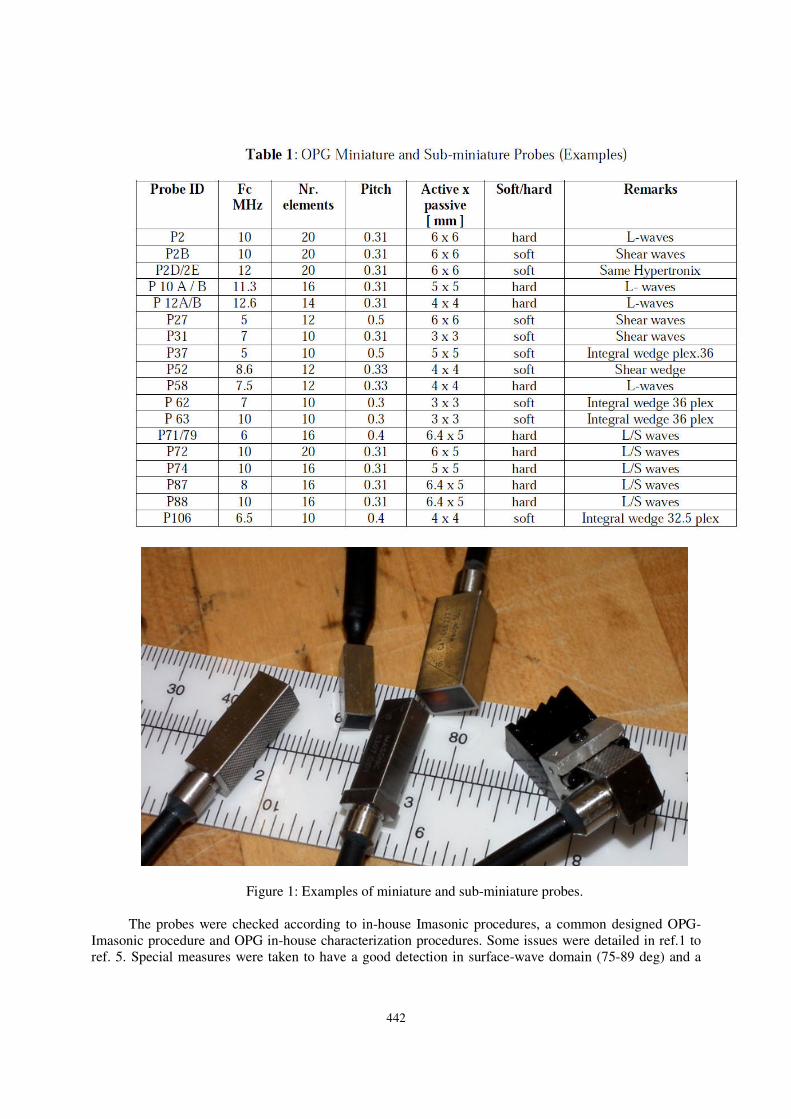
in Table 1 and Figure 1).
442
Figure 1: Examples of miniature and sub-miniature probes.
The probes were checked according to in-house Imasonic procedures, a common designed OPG-
Imasonic procedure and OPG in-house characterization procedures. Some issues were detailed in ref.1 to
ref. 5. Special measures were taken to have a good detection in surface-wave domain (75-89 deg) and a
443
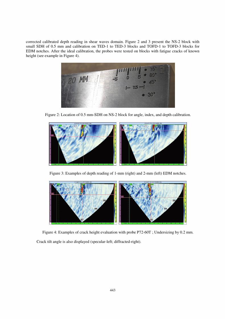
corrected calibrated depth reading in shear waves domain. Figure 2 and 3 present the NS-2 block with
small SDH of 0.5 mm and calibration on TED-1 to TED-3 blocks and TOFD-1 to TOFD-3 blocks for
EDM notches. After the ideal calibration, the probes were tested on blocks with fatigue cracks of known
height (see example in Figure 4).
Figure 2: Location of 0.5 mm-SDH on NS-2 block for angle, index, and depth calibration.
Figure 3: Examples of depth reading of 1-mm (right) and 2-mm (left) EDM notches.
Figure 4: Examples of crack height evaluation with probe P72-60T ; Undersizing by 0.2 mm.
Crack tilt angle is also displayed (specular-left; diffracted-right).
444
FIELD EXAMPLES
Outlet pipe of main valve – Crack in Excavation
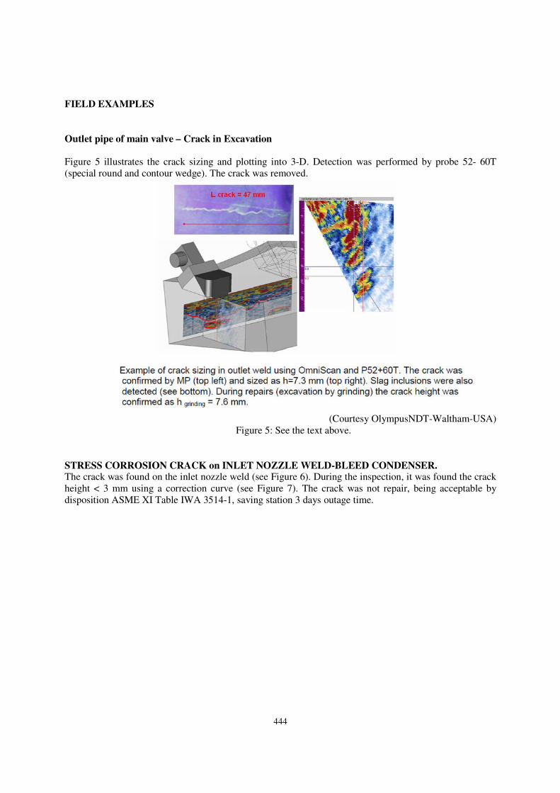
Figure 5 illustrates the crack sizing and plotting into 3-D. Detection was performed by probe 52- 60T
(special round and contour wedge). The crack was removed.
(Courtesy OlympusNDT-Waltham-USA)
Figure 5: See the text above.
STRESS CORROSION CRACK on INLET NOZZLE WELD-BLEED CONDENSER.
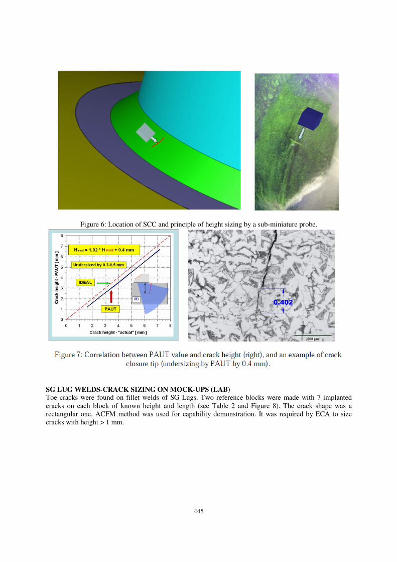
The crack was found on the inlet nozzle weld (see Figure 6). During the inspection, it was found the crack
height < 3 mm using a correction curve (see Figure 7). The crack was not repair, being acceptable by
disposition ASME XI Table IWA 3514-1, saving station 3 days outage time.
445
Figure 6: Location of SCC and principle of height sizing by a sub-miniature probe.
SG LUG WELDS-CRACK SIZING ON MOCK-UPS (LAB)
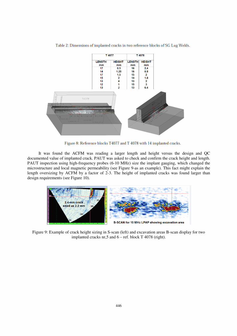
Toe cracks were found on fillet welds of SG Lugs. Two reference blocks were made with 7 implanted
cracks on each block of known height and length (see Table 2 and Figure 8). The crack shape was a
rectangular one. ACFM method was used for capability demonstration. It was required by ECA to size
cracks with height > 1 mm.
446
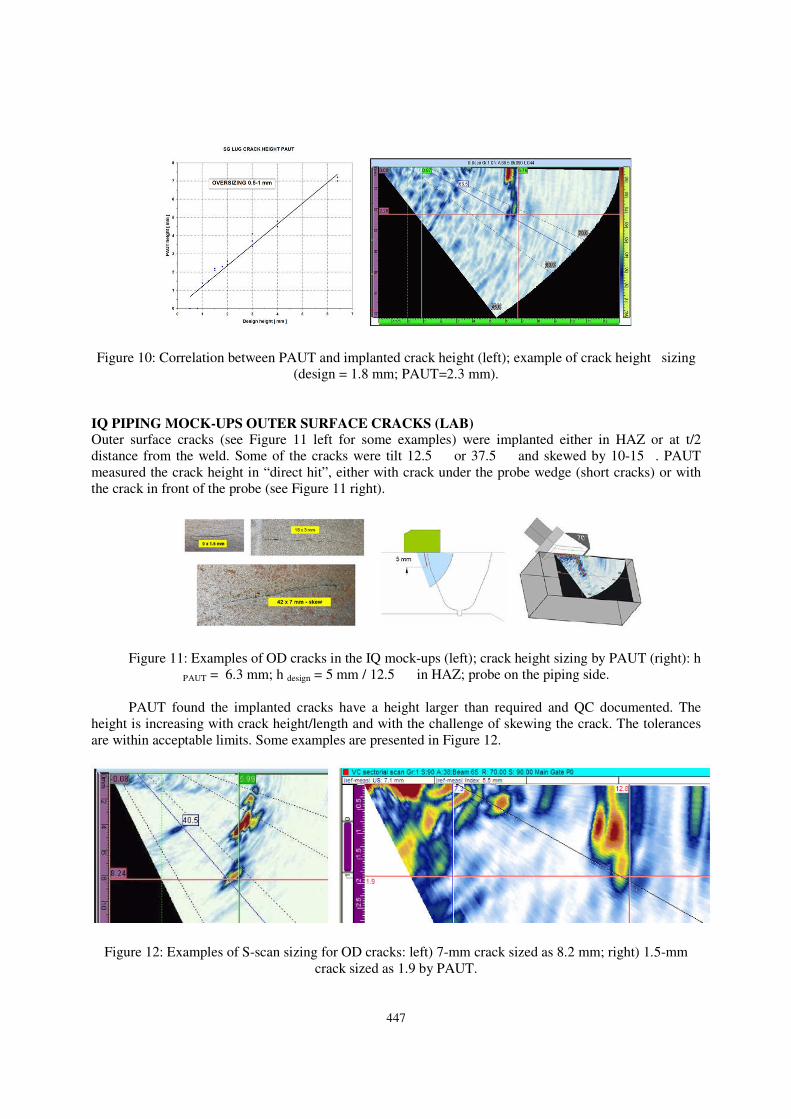
It was found the ACFM was reading a larger length and height versus the design and QC
documented value of implanted crack. PAUT was asked to check and confirm the crack height and length.
PAUT inspection using high-frequency probes (6-10 MHz) size the implant gauging, which changed the
microstructure and local magnetic permeability (see Figure 9-as an example). This fact might explain the
length oversizing by ACFM by a factor of 2-3. The height of implanted cracks was found larger than
design requirements (see Figure 10).
Figure 9: Example of crack height sizing in S-scan (left) and excavation areas B-scan display for two
implanted cracks nr,5 and 6 – ref. block T 4078 (right).
447
Figure 10: Correlation between PAUT and implanted crack height (left); example of crack height sizing
(design = 1.8 mm; PAUT=2.3 mm).
IQ PIPING MOCK-UPS OUTER SURFACE CRACKS (LAB)
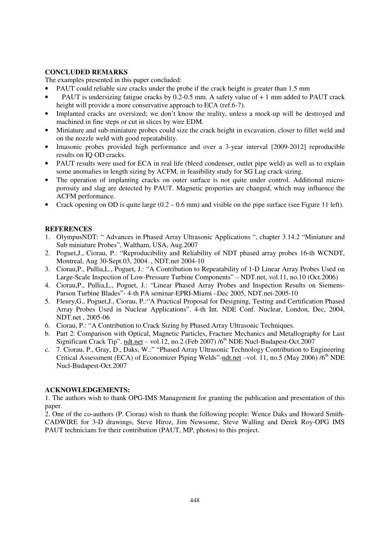
Outer surface cracks (see Figure 11 left for some examples) were implanted either in HAZ or at t/2
distance from the weld. Some of the cracks were tilt 12.5��or 37.5��and skewed by 10-15�. PAUT
measured the crack height in “direct hit”, either with crack under the probe wedge (short cracks) or with
the crack in front of the probe (see Figure 11 right).
Figure 11: Examples of OD cracks in the IQ mock-ups (left); crack height sizing by PAUT (right): h
PAUT = 6.3 mm; h design = 5 mm / 12.5��in HAZ; probe on the piping side.
PAUT found the implanted cracks have a height larger than required and QC documented. The
height is increasing with crack height/length and with the challenge of skewing the crack. The tolerances
are within acceptable limits. Some examples are presented in Figure 12.
Figure 12: Examples of S-scan sizing for OD cracks: left) 7-mm crack sized as 8.2 mm; right) 1.5-mm
crack sized as 1.9 by PAUT.
448
CONCLUDED REMARKS
The examples presented in this paper concluded:
• PAUT could reliable size cracks under the probe if the crack height is greater than 1.5 mm
• �PAUT is undersizing fatigue cracks by 0.2-0.5 mm. A safety value of + 1 mm added to PAUT crack
height will provide a more conservative approach to ECA (ref.6-7).
• Implanted cracks are oversized; we don’t know the reality, unless a mock-up will be destroyed and
machined in fine steps or cut in slices by wire EDM.
• Miniature and sub-miniature probes could size the crack height in excavation, closer to fillet weld and
on the nozzle weld with good repeatability.
• Imasonic probes provided high performance and over a 3-year interval [2009-2012] reproducible
results on IQ OD cracks.
• PAUT results were used for ECA in real life (bleed condenser, outlet pipe weld) as well as to explain
some anomalies in length sizing by ACFM, in feasibility study for SG Lug crack sizing.
• The operation of implanting cracks on outer surface is not quite under control. Additional micro-
porosity and slag are detected by PAUT. Magnetic properties are changed, which may influence the
ACFM performance.
• Crack opening on OD is quite large (0.2 – 0.6 mm) and visible on the pipe surface (see Figure 11 left).
REFERENCES 1. OlympusNDT: “ Advances in Phased Array Ultrasonic Applications “, chapter 3.14.2 “Miniature and
Sub miniature Probes”, Waltham, USA, Aug.2007
2. Poguet,J., Ciorau, P.: “Reproducibility and Reliability of NDT phased array probes 16-th WCNDT,
Montreal, Aug 30-Sept.03, 2004. , NDT.net 2004-10
3. Ciorau,P., Pullia,L., Poguet, J.: “A Contribution to Repeatability of 1-D Linear Array Probes Used on
Large-Scale Inspection of Low-Pressure Turbine Components” – NDT.net, vol.11, no.10 (Oct.2006)
4. Ciorau,P., Pullia,L., Poguet, J.: “Linear Phased Array Probes and Inspection Results on Siemens-
Parson Turbine Blades”- 4-th PA seminar-EPRI-Miami –Dec 2005, NDT.net-2005-10
5. Fleury,G., Poguet,J., Ciorau, P.:“A Practical Proposal for Designing, Testing and Certification Phased
Array Probes Used in Nuclear Applications”. 4-th Int. NDE Conf. Nuclear, London, Dec, 2004,
NDT.net , 2005-06
6. Ciorau, P.: “A Contribution to Crack Sizing by Phased Array Ultrasonic Techniques.
b. Part 2: Comparison with Optical, Magnetic Particles, Fracture Mechanics and Metallography for Last
Significant Crack Tip”. ndt.net – vol.12, no.2 (Feb 2007) /6th NDE Nucl-Budapest-Oct.2007
c. 7. Ciorau, P., Gray, D., Daks, W.:” “Phased Array Ultrasonic Technology Contribution to Engineering
Critical Assessment (ECA) of Economizer Piping Welds”-ndt.net –vol. 11, no.5 (May 2006) /6th NDE
Nucl-Budapest-Oct.2007
ACKNOWLEDGEMENTS:
1. The authors wish to thank OPG-IMS Management for granting the publication and presentation of this
paper.
2. One of the co-authors (P. Ciorau) wish to thank the following people: Wence Daks and Howard Smith-
CADWIRE for 3-D drawings, Steve Hiroz, Jim Newsome, Steve Walling and Derek Roy-OPG IMS
PAUT technicians for their contribution (PAUT, MP, photos) to this project.


![Fatigue Testing of Pipeline Welds and Heat …and the fatigue crack growth rate (FCGR) [10], unlike results observed with monotonically increasing loading such as tensile strength](https://img.pdfslide.us/doc/110x75/5e587e86c4154c6fd13029fa/fatigue-testing-of-pipeline-welds-and-heat-and-the-fatigue-crack-growth-rate-fcgr.jpg)