Embed Size (px)
Citation preview
Southern Nuclear Operating Company, Inc. 42 Inverness Center Parkway Birmingham, AL 35242
June 29, 2015
Docket Nos.: 52-025 ND-15-1152 52-026 10 CFR 50.90 U.S. Nuclear Regulatory Commission Document Control Desk Washington, DC 20555-0001
Southern Nuclear Operating Company Vogtle Electric Generating Plant Units 3 and 4
Revision 2 to Request for License Amendment: Use of AWS D1.1-2000 Criteria for Structural Welds (LAR-15-009R2)
Ladies and Gentlemen:
Pursuant to 10 CFR 52.98(c) and in accordance with 10 CFR 50.90, Southern Nuclear Operating Company (SNC) requested an amendment to the combined licenses (COLs) for Vogtle Electric Generating Plant (VEGP) Units 3 and 4 (License Numbers NPF-91 and NPF-92, respectively) on May 26, 2015. The requested amendment proposes to depart from Tier 2* and associated Tier 2 information in the Updated Final Safety Analysis Report (UFSAR) (which includes the plant-specific DCD Tier 2 information) to revise the application of American Institute of Steel Construction (AISC) N690-1994, Specification for the Design, Fabrication, and Erection of Steel Safety-Related Structures for Nuclear Facilities, to allow use of American Welding Society (AWS) D1.1-2000, Structural Welding Code - Steel, in lieu of the AWS D1.1-1992 edition identified in AISC N690-1994. The original LAR was supplemented by letter on May 28, 2015 (LAR-15-009S, SNC correspondence ND-15-0968), to revise the Tier 2* designations of some of the proposed changes to the UFSAR, and revised by letter on June 9, 2015 (LAR-15-009R1, SNC correspondence ND-15-1036), to address Nuclear Regulatory Commission (NRC) Staff questions and comments.
This second revision to the request for amendment (LAR-15-009R2) provides additional information related to the discussions of the proposed changes to the UFSAR language as provided in previous Enclosure 4 and additional revisions to the proposed changes to the UFSAR language as provided in previous Enclosure 5. These changes reflect the discussions from public meetings held on June 11 and June 18, 2015.
Enclosure 6 provides a complete replacement for the description, technical evaluation, regulatory evaluation (including the Significant Hazards Consideration Determination) and environmental considerations for the proposed changes (as most recently provided in Enclosure 4). Enclosure 7 provides a complete replacement for the markups depicting the requested changes to the VEGP Units 3 and 4 UFSAR (as most recently provided in Enclosure 5).
U.S. Nuclear Regulatory Commission ND-15-1152 Page 2 of 4
SNC also submitted a Preliminary Amendment Request on June 1, 2015, regarding use of these changes during construction prior to NRC action on the LAR.
This LAR does not attempt to address a related partial joint penetration and fillet weld combination weld issue identified by an NRC inspector. The combination welds are being addressed separately.
This letter contains no regulatory commitments.
SNC requests NRC staff approval of the license amendment by July 29, 2015, to support installation of seismic Category I and seismic Category II structures. Delayed approval of this license amendment could result in a delay in additional welding on seismic Category I and II structures and subsequent dependent construction activities. SNC expects to implement this proposed amendment within 30 days of approval of the requested changes.
In accordance with 10 CFR 50.91, SNC is notifying the State of Georgia of this LAR revision by transmitting a copy of this letter and enclosures to the designated State Official.
Should you have any questions, please contact Mr. Jason Redd at (205) 992-6435.
Mr. Wesley A. Sparkman states that: he is the Regulatory Affairs Licensing Manager, Nuclear Development, of Southern Nuclear Operating Company; he is authorized to execute this oath on behalf of Southern Nuclear Operating Company; and to the best of his knowledge and belief, the facts set forth in this letter are true.
Respectfully submitted,
SOUTHERN NUCLEAR OP
WAS/ERG/kms
Sworn to and subscribed before me this ?-~ day of cli0<?L NotaryPublic: 7~J ,~ ~ My commission expires: ~ I (2, ~((0
'2015 !1,,,,,, ............. ,,. '!II.,,.. o.'t.R T .. ·~. ~ -•••
~~ c..~"'········~ "' ""~..J '\ .~ f -.J •• •• ~ . •• •• v~ ~. '" ~ ~-· ~ *'' .\ ~ .; \
l 0:: '""t;'h-'i. =~:~1- :··~: ... : :! : 0 • _, . 'ks : : \ ' l'h • ·~~ : : ~· ~ . ~ ~·· '% ~ ' .I.:.: 4 \ ~<Y·... .~. <l !' ·~· Cb l il'! ,...J •• ...- to.. ..
~ ,..~ ········· ~,- ~ l'.t,, _, ·., AL a.e~ ,• ~,,~ "' .,•""' ,,, ............. .
U. S. Nuclear Regulatory Commission ND-15-1152 Page 3 of 4
Enclosures: 1) and 2) Provided with original submittal (completely replaced)
3) Provided with Supplement 1 submittal (completely replaced)
4) and 5) Provided with Revision 1 submittal (completely replaced)
6) Vogtle Electric Generating Plant (VEGP) Units 3 and 4 – Revised Request for License Amendment Regarding Use of AWS D1.1-2000 Criteria for Structural Welds (LAR-15-009R2)
7) Vogtle Electric Generating Plant (VEGP) Units 3 and 4 - Revised Proposed Changes to Licensing Basis Documents (LAR-15-009R2)
cc: Southern Nuclear Operating Company / Georgia Power Company
Mr. S. E. Kuczynski (w/o enclosures) Mr. J. A. Miller Mr. D. G. Bost (w/o enclosures) Mr. M. D. Meier Mr. M. D. Rauckhorst (w/o enclosures) Mr. J. T. Gasser (w/o enclosures) Mr. D. H. Jones (w/o enclosures) Ms. K. D. Fili (w/o enclosures) Mr. D. R. Madison Mr. T.W. Yelverton Mr. B. H. Whitley Mr. C. R. Pierce Mr. D. L. Fulton Mr. M. J. Yox Mr. J. C. Harrelson Mr. W. A. Sparkman Mr. J. P. Redd Document Services RTYPE: VND.LI.L00 File AR.01.02.06 Nuclear Regulatory Commission Mr. V. M. McCree (w/o enclosures) Mr. M. Delligatti (w/o enclosures) Mr. L. Burkhart (w/o enclosures) Mr. P. B. Kallan (w/o enclosures) Mr. C. Patel Ms. D. L. McGovern Mr. B. M. Bavol Ms. R. Reyes Ms. M. A. Sutton Mr. M. E. Ernstes Mr. G. Khouri Mr. L. M. Cain Mr. J. D. Fuller
U. S. Nuclear Regulatory Commission ND-15-1152 Page 4 of 4
Mr. C. B. Abbott Ms. S. Temple Mr. I. A. Anchondo State of Georgia Mr. J. H. Turner Oglethorpe Power Corporation Mr. M. W. Price Ms. K. T. Haynes Ms. A. Whaley Municipal Electric Authority of Georgia Mr. J. E. Fuller Mr. S. M. Jackson Dalton Utilities Mr. D. Cope CB&I Mr. J. Simmons (w/o enclosures) Ms. K. Stoner (w/o enclosures) Mr. C. A. Castell Westinghouse Electric Company, LLC Mr. R. Easterling (w/o enclosures) Mr. S. W. Gray (w/o enclosures) Mr. J. W. Crenshaw (w/o enclosures) Mr. C. D. Churchman (w/o enclosures) Mr. L. Woodcock Mr. P. A. Russ Mr. G. F. Couture Mr. M. Y. Shaqqo Other Mr. J. E. Hesler, Bechtel Power Corporation Ms. K. K. Patterson, Tetra Tech NUS, Inc. Dr. W. R. Jacobs, Jr., Ph.D., GDS Associates, Inc. Mr. S. Roetger, Georgia Public Service Commission Ms. S. W. Kernizan, Georgia Public Service Commission Mr. K. C. Greene, Troutman Sanders Mr. S. Blanton, Balch Bingham Mr. R. Grumbir, APOG Mr. J. R. Bouknight, South Carolina Electric & Gas Company Mr. D. Kersey, South Carolina Electric & Gas Company Mr. B. Kitchen, Duke Energy Mr. S. Franzone, Florida Power & Light
Southern Nuclear Operating Company
Vogtle Electric Generating Plant (VEGP) Units 3 and 4
ND-15-1152
Enclosure 6
Revised Request for License Amendment Regarding
Use of AWS D1.1-2000 Criteria for Structural Welds
(LAR-15-009R2)
(This Enclosure consists of 22 pages, including this cover page)
ND-15-1152 Enclosure 6 Use of AWS D1.1-2000 Criteria for Structural Welds (LAR-15-009R2)
Page 2 of 22
Table of Contents
1. Summary Description
2. Detailed Description
3. Technical Evaluation
4. Regulatory Evaluation
4.1 Applicable Regulatory Requirements/Criteria
4.2 Precedent
4.3 Significant Hazards Consideration Determination
4.4 Conclusions
5. Environmental Considerations
6. References
ND-15-1152 Enclosure 6 Use of AWS D1.1-2000 Criteria for Structural Welds (LAR-15-009R2)
Page 3 of 22
1. Summary Description
Pursuant to 10 CFR 52.98(c) and in accordance with 10 CFR 50.90, Southern Nuclear Operating Company (SNC), the licensee for Vogtle Electric Generating Plant (VEGP) Units 3 and 4, requests an amendment to Combined License (COL) Numbers NPF-91 and NPF-92, for VEGP Units 3 and 4, respectively.
This activity changes the design of welding for structures in the nuclear island and in the seismic Category II portions of the turbine building and annex building. The design change incorporates criteria of American Welding Society (AWS) D1.1-2000, Structural Welding Code - Steel, into the design of structures designed to the requirements of American Institute of Steel Construction (AISC) N690-1994, Specification for the Design, Fabrication, and Erection of Steel Safety-Related Structures for Nuclear Facilities, for use in lieu of the AWS D1.1-1992 version identified in AISC N690-1994. AWS D1.1-2000 is used to supplement the provisions in AISC N690-1994 for sizing criteria for welds joining steel tubular members, weld metal to use for ASTM A992 steel, and the application of directionality in the evaluation of fillet welds.
Supplemental provisions are added to the provisions in AWS D1.1-2000 for the application of directionality for linear fillet weld groups concentrically loaded in-plane to the axis of the weld that include elements oriented both longitudinally and transversely to the direction of applied load to address deformation of the welds. The change also specifies extension of the application of directionality provisions to linear and concentrically loaded (i.e., loaded through the center of gravity of the weld group) rectangular and circular fillet weld groups loaded out-of-plane to the axis of the weld to supplement the conditions specified in AWS D1.1-2000.
The use of AWS D1.1-2000 is necessary for future welding and for installed welding to resolve an item noted by a Nuclear Regulatory Commission (NRC) inspector. Note that this LAR (15-009) does not attempt to address a partial joint penetration (PJP) and fillet weld combination weld issue also identified by an NRC inspector. The combination welds are being addressed separately.
Changes to Tier 2 and Tier 2* information in the licensing basis are included to allow the use of the AWS D1.1-2000 criteria and supplemental provisions.
2. Detailed Description
The requirements for the steel portion of the nuclear island structures are based on the requirements in AISC N690-1994. AISC N690 includes the use of AWS D1.1-1992 for welding requirements including the design and sizing of the welds. The requirements for the concrete portion of the nuclear island structures are based on American Concrete Institute (ACI) 349-01. ACI 349-01 includes the use of AWS D1.1-2000 for welding requirements.
ND-15-1152 Enclosure 6 Use of AWS D1.1-2000 Criteria for Structural Welds (LAR-15-009R2)
Page 4 of 22
The proposed change simplifies the application of requirements from different codes and standards to the structural design through consistent use of the criteria for weld design in AWS D1.1-2000. The Updated Final Safety Analysis Report (UFSAR) cites AISC N690 and ACI 349 as applicable codes for these structural designs. Reference to AWS D1.1-2000 is added to these citations in the UFSAR as part of the proposed change for use in lieu of the AWS D1.1-1992 version identified in AISC N690-1994. AWS D1.1-2000 is added for use to replace and supplement specific provisions in AISC N690-1994 related to welding as identified in the proposed changes to UFSAR Subsections 3.8.3.2 and 3.8.4.2.
Reference to AWS D1.1-2000 is added where AISC N690 is identified as the applicable code for seismic Category I structures and components in UFSAR Subsections 3.6.2.3.4.2 (pipe whip restraints), 3A.1 (heating, ventilation and air conditioning (HVAC) ducts and their supports), 3F.1 (cable trays and their supports), and 3H.3.1 (auxiliary and shield buildings).
The technical changes incorporated into AWS D1.1-2000 either add more restrictive provisions or provide specific provisions for weld details not previously defined as follows:
• The sizing criteria for complete joint penetration groove welds for welding of tubular members in AWS D1.1-2000, Section 2.3.4.1 provide specific provisions for a weld configuration not included in AISC N690-1994. The provisions for groove welds for welding of tubular members are cited to clearly identify the provisions for such connections. Provisions for welded connections for tubular steel members (hollow structural shapes) are specifically excluded from AISC N690-1994.
• AWS D1.1-2000, Section 3.3 and Table 3.1 provide information not available in AISC N690-1994, Section Q1.4.4 regarding the weld metal to use for ASTM A992 structural shapes. The need for the addition of weld metal for A992 steel is driven by industry changes in structural steel shape availability, as ASTM A992 has generally replaced ASTM A36 for structural steel shapes.
• The criteria on the range of weld angles in AWS D1.1-2000, Figure 3.11 – Detail C, over which provisions for skewed T joints apply, are more restrictive than what was included in AWS D1.1-1992. These criteria do not replace or supplement specific provisions in AISC N690-1994 and therefore are not specifically included UFSAR text.
The information on allowable stress for weld strength is included in AISC N690-1994 Section Q1.5.3 and Table Q1.5.3. The technical changes included in the AWS D1.1-2000 edition also include criteria that consider load directionality on fillet welds and include an increase factor on structural fillet weld strength. This provision in AWS D1.1-2000 provides a supplemental set of provisions that are not included in AISC N690-1994 and AWS D1.1-1992.
The proposed change to the UFSAR also specifies that the use of the directionality provisions applies to rectangular and circular fillet weld groups concentrically loaded out-of-plane to the axis of the weld. This is a supplementary change because AWS D1.1-2000 does not specifically include application to these load configurations. The changes that permit the use of
ND-15-1152 Enclosure 6 Use of AWS D1.1-2000 Criteria for Structural Welds (LAR-15-009R2)
Page 5 of 22
provisions in AWS D1.1-2000 for the application of directionality are supplemented with additional provisions for linear weld groups that include elements oriented both longitudinally and transversely to the direction of the applied weld. The provisions added are consistent with provisions in AWS D1.1-2010 that address deformation capability of the elements in linear weld groups that combine elements oriented both longitudinally and transversely to the direction of applied load concentrically loaded in plane to the axis of the weld.
The portions of the turbine building and annex building adjacent to the auxiliary building are designed as seismic Category II structures to provide for structural integrity during seismic events. The seismic Category II portions of the turbine building and annex building are designed to the criteria of AISC N690 and ACI 349 as identified in UFSAR Subsection 3.7.2. Reference to AWS D1.1-2000 is also added to the list of codes for the design, qualification, fabrication, and inspection of the welding of seismic Category II structures in the UFSAR as part of the proposed change in UFSAR Subsections 3.3.2.3, 3.7.2, and 3.7.2.8.3. As part of this change, the application of the design requirements is changed to specifically include the seismic Category II portions of the turbine building by adding reference to the turbine building to the paragraph describing requirements for seismic Category II structures. The approved Design Control Document (Revision 19), Subsection 3.3.2.3 (fifth paragraph) identified the entire turbine building as “designed to seismic Category I structure tornado loading.” While a previous license amendment [Vogtle 3 and 4 COL Amendment No. 8] revised that fifth paragraph to specifically address the main portion of the turbine building, the change proposed in this LAR makes the content of Subsection 3.3.2.3 consistent with the previous discussions of the design of the first bay of the turbine building with regard to tornado loading.
This change activity does not change the supplemental requirements for steel and concrete structures in UFSAR Subsection 3.8.4.5. This change activity does not change the supplemental requirements for structural modules described in UFSAR Subsection 3.8.3, except for the changes described for AISC N690. This change activity does not change the design requirements for the shield building in UFSAR Subsection 3.8.4.5.5.
Licensing Basis Change Descriptions
The following describes the changes to Tier 2 and Tier 2* information in that it is proposed that AWS D1.1-2000 and supplemental provisions be identified as acceptable for use in lieu of the AWS D1.1-1992 version identified in the referenced design code, AISC N690-1994.
Reference to AWS D1.1-2000 is added where AISC N690 is identified as the applicable code throughout the UFSAR to provide consistent use of AWS D1.1 whenever AISC N690 is used. These additions are reflected in UFSAR Subsections 3.3.2.3, 3.6.2.3.4.2, 3.7.2, 3.7.2.8.3, 3.8.3.2, 3.8.4.2, 3A.1, 3F.1, and 3H.3.1. In UFSAR Subsections 3.8.3.2 and 3.8.4.2 specific provisions in AWS D1.1-2000 which replace provisions in AISC N690-1994 are identified. Also supplemental provisions applicable to the application of directionality for evaluation of fillet welds, consistent with provisions in AWS D1.1-2010, are identified. In locations where the AISC N690-1994 code is identified as Tier 2* information, the allowance to use AWS D1.1-2000 is
ND-15-1152 Enclosure 6 Use of AWS D1.1-2000 Criteria for Structural Welds (LAR-15-009R2)
Page 6 of 22
also identified as Tier 2* information. It is noted that AISC N690 is also referenced in UFSAR Subsection 5.4.10.1 for component supports but this section discussion already refers back to UFSAR Subsection 3.8.3 which is included in the proposed changes to include the use of AWS D1.1-2000.
1. In the third paragraph of UFSAR Subsection 3.3.2.3, incorporate the requirements for the turbine building and add reference to AWS D1.1-2000 for the design, qualification, fabrication, and inspection of seismic Category II structures. Also add a cross reference to supplemental requirements in UFSAR Subsections 3.8.4.4.1 and 3.8.4.5 for consistency with other code reference discussions.
2. In UFSAR Subsection 3.6.2.3.4.2, add reference to AWS D1.1-2000.
3. In the third paragraph of UFSAR Subsection 3.7.2, add reference to AWS D1.1-2000 for the design, qualification, fabrication, and inspection of seismic Category II structures.
4. In the third paragraph of UFSAR Subsection 3.7.2.8.3, add reference to AWS D1.1-2000 for the design, qualification, fabrication, and inspection of the turbine building first bay. Also add a cross reference to supplemental requirements in UFSAR Subsections 3.8.4.4.1 and 3.8.4.5 for consistency with other code reference discussions.
5. In UFSAR Subsection 3.8.3.2,
a. Add an entry for AWS D1.1-2000,
b. Specifically identify where this welding code is used in lieu of the provisions of AISC N690-1994,
c. Include information on the application of directionality for linear fillet welds and rectangular and circular weld groups concentrically loaded out-of-plane to the axis of the weld to supplement the configurations specified in AWS D1.1-2000, and
d. Include information on the application of directionality for linear fillet weld groups that include both longitudinally and transversely oriented elements concentrically loaded in-plane to the axis of the weld.
6. In UFSAR Subsection 3.8.4.2,
a. Add an entry for AWS D1.1-2000,
b. Specifically identify where this welding code is used in lieu of the provisions of AISC N690-1994,
c. Include information on the application of directionality for linear fillet welds and rectangular and circular weld groups concentrically loaded out-of-plane to the axis of the weld to supplement the configurations specified in AWS D1.1-2000, and
d. Include information on the application of directionality for linear fillet weld groups that include both longitudinally and transversely oriented elements concentrically loaded in-plane to the axis of the weld.
ND-15-1152 Enclosure 6 Use of AWS D1.1-2000 Criteria for Structural Welds (LAR-15-009R2)
Page 7 of 22
7. In UFSAR Subsection 3A.1, add reference to AWS D1.1-2000.
8. In UFSAR Subsection 3F.1, add reference to AWS D1.1-2000.
9. In UFSAR Subsection 3H.3.1, add reference to AWS D1.1-2000.
3. Technical Evaluation
The changes involve the use of AWS D1.1-2000 and the addition of supplemental provisions to provide criteria for the weld design, qualification, fabrication, and inspection for structures in the nuclear island and seismic Category II portions of the annex building and turbine building. The evaluations of these structures use criteria and requirements from applicable portions of AISC N690 and ACI 349. AISC N690-1994 is the code of record for design certification for steel design and it includes the use of AWS D1.1-1992 and other provisions related to welding. ACI 349-01 is the code of record for the AP1000 design certification for structural concrete design and includes the use of AWS D1.1-2000.
Specifically including the turbine building first bay under the requirements for seismic Category II in UFSAR Subsection 3.3.2.3 is a clarification of the requirements for the turbine building to be consistent with the requirements in UFSAR Subsection 3.7.2. UFSAR Subsections 3.3.2.3 and 3.7.2.8.3 are also revised for consistency with UFSAR Subsection 3.7.2 to include references to the supplemental requirements in UFSAR Subsections 3.8.4.4.1 and 3.8.4.5.
The proposed change adds AWS D1.1-2000 to the list of applicable codes and standards in the UFSAR. The AWS D1.1-2000 code is a general purpose structural welding code. It is developed and revised as a voluntary consensus standard by industry experts experienced in welding and weld design. Changes and additions to the AWS D1.1 code are supported by tests and evaluations generally reported in peer reviewed publications. Use of provisions in AWS D1.1-2000 provides an appropriate, conservative set of provisions for structural welding.
Section-by-section review of AWS D1.1-2000 demonstrates that the AWS D1.1-1992 requirements are met. Requirements provided in AWS D1.1-2000 are either: 1) equivalent; 2) administrative changes; 3) additional technical requirements that either add detail or fill requirement gaps; 4) additional technical requirements provided to standardize processes and procedures; or 5) alternative methods for evaluating fillet welds (i.e., an increase in strength due to loading direction). EPRI NP-5380 visual inspection acceptance criteria continue to be applied in accordance with AISC N690-1994, Section Q1.17.1.
A reconciliation review was completed to assess the differences between the AWS D1.1-1992 and AWS D1.1-2000 codes. The differences included in AWS D1.1-2000 add more restrictive requirements (e.g., requirements on maximum weld angle for skewed T joints and additional requirements for the minimum weld size for partial joint penetration groove welds in welded connections of tubular steel elements) or provide more specific requirements for weld design
ND-15-1152 Enclosure 6 Use of AWS D1.1-2000 Criteria for Structural Welds (LAR-15-009R2)
Page 8 of 22
details (e.g., specific requirements for minimum complete joint penetration groove weld size for tubular members) that were not specified or were excluded in AWS D1.1-1992 or AISC N690-1994. AWS D1.1-2000 includes requirements for partial joint penetration groove welds in welded connections of tubular steel elements. AISC N690-1994 excludes these weld requirements as not being needed for structures in nuclear power plants. The AP1000 design does use tubular steel elements in structures, structural frames, and connections of piping and component supports to safety related structures. Section 2.3.4.1 of AWS D1.1-2000 provides requirements for sizing of partial joint penetration groove welds in welded connections of tubular steel elements. That section is cited in the proposed changes to the UFSAR to clarify that these provisions are used despite the exclusion in AISC N690-1994.
A review was also completed to assess the provisions in AWS D1.1-2000 used to replace and supplement specific provisions in AISC N690-1994. The review identified provisions in AWS D1.1-2000 that provide requirements for features and configurations not included in AISC N690-1994 and requirements and criteria that are more specific in AWS D1.1-2000. The use of the AWS D1.1-2000 criteria and the supplemental provisions does not result in a significant increase in the stress in the weld. AWS D1.1-2000 adds weld metal requirements for ASTM A992 steel. ASTM A992 was not included in AWS D1.1-1992. ASTM A992 has generally replaced ASTM A36 for structural steel shapes and is utilized in the AP1000 design. These changes are not adverse to the performance or function of the steel structures. Use of the criteria in AWS D1.1-2000 for these features and configurations provides more certainty that the appropriate criteria are used. The safety margin is not significantly reduced with the use of the additional requirements. Therefore, the use of AWS D1.1-2000 and the supplemental provisions for the design and evaluation of the structures in the nuclear island and the seismic Category II structures in the turbine and annex buildings is not an adverse change with respect to the function of these structures.
These changes are not adverse to the performance or function of the steel structures. Thus, these changes can be similarly applied to welds in the AP1000 to continue to provide the necessary safety margin.
Directionality Provisions Included in AWS D1.1-2000
Technical changes included in the AWS D1.1-2000 edition include criteria that consider load directionality in linear fillet welds and include an increase factor on structural fillet weld strength. The increase in fillet weld strength in a weld group is dependent upon the angle of loading with respect to the weld axis, as provided in AWS D1.1-2000 Sections 2.14.4 and 2.14.5. The increase in strength for a fillet weld group loaded transverse to the axis of the weld as opposed to one loaded parallel to the axis of the weld has long been recognized in both AISC and AWS codes. This is because the stress distribution in the weld varies with the relative orientation of the load and weld axes.
AISC N690-1994 Commentary Section CQ1.5.3 states that “As in the past, the same allowable value is given to a transverse as to a longitudinal weld, even though the force the former can
ND-15-1152 Enclosure 6 Use of AWS D1.1-2000 Criteria for Structural Welds (LAR-15-009R2)
Page 9 of 22
resist is substantially greater than that of the latter.” The AWS D1.1-1992 Commentary C8.2 Part B (Allowable Unit Stresses) states that “A working stress equal to 0.3 times the tensile strength of the filler metal, as designated by the electrode classification, applied to the throat of a fillet weld has been shown by tests to provide a factor of safety ranging from 2.2 for shearing forces parallel to the longitudinal axis of the weld, to 4.6 for forces normal to the axis, under service loading.”
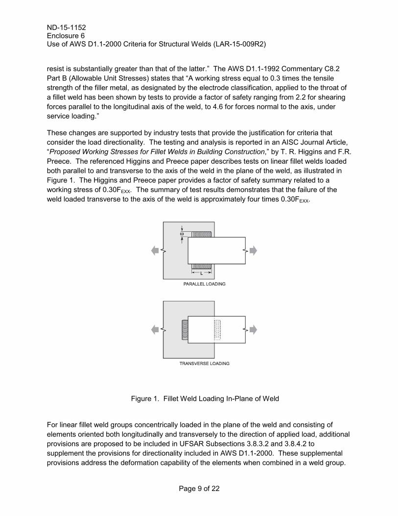
These changes are supported by industry tests that provide the justification for criteria that consider the load directionality. The testing and analysis is reported in an AISC Journal Article, “Proposed Working Stresses for Fillet Welds in Building Construction,” by T. R. Higgins and F.R. Preece. The referenced Higgins and Preece paper describes tests on linear fillet welds loaded both parallel to and transverse to the axis of the weld in the plane of the weld, as illustrated in Figure 1. The Higgins and Preece paper provides a factor of safety summary related to a working stress of 0.30FEXX. The summary of test results demonstrates that the failure of the weld loaded transverse to the axis of the weld is approximately four times 0.30FEXX.
Figure 1. Fillet Weld Loading In-Plane of Weld
For linear fillet weld groups concentrically loaded in the plane of the weld and consisting of elements oriented both longitudinally and transversely to the direction of applied load, additional provisions are proposed to be included in UFSAR Subsections 3.8.3.2 and 3.8.4.2 to supplement the provisions for directionality included in AWS D1.1-2000. These supplemental provisions address the deformation capability of the elements when combined in a weld group.
ND-15-1152 Enclosure 6 Use of AWS D1.1-2000 Criteria for Structural Welds (LAR-15-009R2)
Page 10 of 22
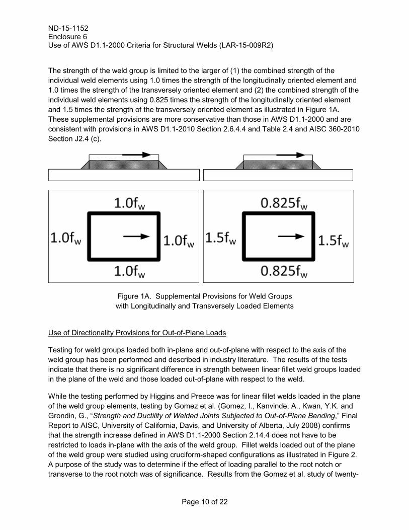
The strength of the weld group is limited to the larger of (1) the combined strength of the individual weld elements using 1.0 times the strength of the longitudinally oriented element and 1.0 times the strength of the transversely oriented element and (2) the combined strength of the individual weld elements using 0.825 times the strength of the longitudinally oriented element and 1.5 times the strength of the transversely oriented element as illustrated in Figure 1A. These supplemental provisions are more conservative than those in AWS D1.1-2000 and are consistent with provisions in AWS D1.1-2010 Section 2.6.4.4 and Table 2.4 and AISC 360-2010 Section J2.4 (c).
Figure 1A. Supplemental Provisions for Weld Groups with Longitudinally and Transversely Loaded Elements
Use of Directionality Provisions for Out-of-Plane Loads
Testing for weld groups loaded both in-plane and out-of-plane with respect to the axis of the weld group has been performed and described in industry literature. The results of the tests indicate that there is no significant difference in strength between linear fillet weld groups loaded in the plane of the weld and those loaded out-of-plane with respect to the weld.
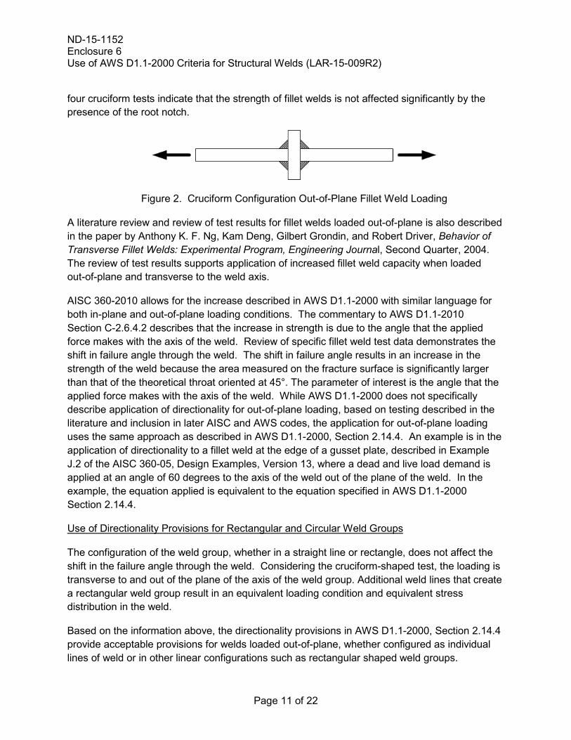
While the testing performed by Higgins and Preece was for linear fillet welds loaded in the plane of the weld group elements, testing by Gomez et al. (Gomez, I., Kanvinde, A., Kwan, Y.K. and Grondin, G., “Strength and Ductility of Welded Joints Subjected to Out-of-Plane Bending,” Final Report to AISC, University of California, Davis, and University of Alberta, July 2008) confirms that the strength increase defined in AWS D1.1-2000 Section 2.14.4 does not have to be restricted to loads in-plane with the axis of the weld group. Fillet welds loaded out of the plane of the weld group were studied using cruciform-shaped configurations as illustrated in Figure 2. A purpose of the study was to determine if the effect of loading parallel to the root notch or transverse to the root notch was of significance. Results from the Gomez et al. study of twenty-
ND-15-1152 Enclosure 6 Use of AWS D1.1-2000 Criteria for Structural Welds (LAR-15-009R2)
Page 11 of 22
four cruciform tests indicate that the strength of fillet welds is not affected significantly by the presence of the root notch.
Figure 2. Cruciform Configuration Out-of-Plane Fillet Weld Loading
A literature review and review of test results for fillet welds loaded out-of-plane is also described in the paper by Anthony K. F. Ng, Kam Deng, Gilbert Grondin, and Robert Driver, Behavior of Transverse Fillet Welds: Experimental Program, Engineering Journal, Second Quarter, 2004. The review of test results supports application of increased fillet weld capacity when loaded out-of-plane and transverse to the weld axis.
AISC 360-2010 allows for the increase described in AWS D1.1-2000 with similar language for both in-plane and out-of-plane loading conditions. The commentary to AWS D1.1-2010 Section C-2.6.4.2 describes that the increase in strength is due to the angle that the applied force makes with the axis of the weld. Review of specific fillet weld test data demonstrates the shift in failure angle through the weld. The shift in failure angle results in an increase in the strength of the weld because the area measured on the fracture surface is significantly larger than that of the theoretical throat oriented at 45°. The parameter of interest is the angle that the applied force makes with the axis of the weld. While AWS D1.1-2000 does not specifically describe application of directionality for out-of-plane loading, based on testing described in the literature and inclusion in later AISC and AWS codes, the application for out-of-plane loading uses the same approach as described in AWS D1.1-2000, Section 2.14.4. An example is in the application of directionality to a fillet weld at the edge of a gusset plate, described in Example J.2 of the AISC 360-05, Design Examples, Version 13, where a dead and live load demand is applied at an angle of 60 degrees to the axis of the weld out of the plane of the weld. In the example, the equation applied is equivalent to the equation specified in AWS D1.1-2000 Section 2.14.4.
Use of Directionality Provisions for Rectangular and Circular Weld Groups
The configuration of the weld group, whether in a straight line or rectangle, does not affect the shift in the failure angle through the weld. Considering the cruciform-shaped test, the loading is transverse to and out of the plane of the axis of the weld group. Additional weld lines that create a rectangular weld group result in an equivalent loading condition and equivalent stress distribution in the weld.
Based on the information above, the directionality provisions in AWS D1.1-2000, Section 2.14.4 provide acceptable provisions for welds loaded out-of-plane, whether configured as individual lines of weld or in other linear configurations such as rectangular shaped weld groups.
ND-15-1152 Enclosure 6 Use of AWS D1.1-2000 Criteria for Structural Welds (LAR-15-009R2)
Page 12 of 22
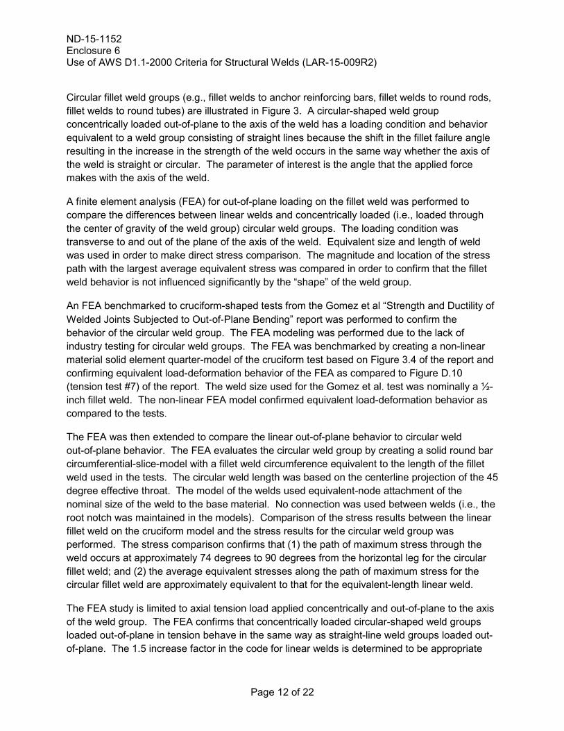
Circular fillet weld groups (e.g., fillet welds to anchor reinforcing bars, fillet welds to round rods, fillet welds to round tubes) are illustrated in Figure 3. A circular-shaped weld group concentrically loaded out-of-plane to the axis of the weld has a loading condition and behavior equivalent to a weld group consisting of straight lines because the shift in the fillet failure angle resulting in the increase in the strength of the weld occurs in the same way whether the axis of the weld is straight or circular. The parameter of interest is the angle that the applied force makes with the axis of the weld.
A finite element analysis (FEA) for out-of-plane loading on the fillet weld was performed to compare the differences between linear welds and concentrically loaded (i.e., loaded through the center of gravity of the weld group) circular weld groups. The loading condition was transverse to and out of the plane of the axis of the weld. Equivalent size and length of weld was used in order to make direct stress comparison. The magnitude and location of the stress path with the largest average equivalent stress was compared in order to confirm that the fillet weld behavior is not influenced significantly by the “shape” of the weld group.
An FEA benchmarked to cruciform-shaped tests from the Gomez et al “Strength and Ductility of Welded Joints Subjected to Out‐of‐Plane Bending” report was performed to confirm the behavior of the circular weld group. The FEA modeling was performed due to the lack of industry testing for circular weld groups. The FEA was benchmarked by creating a non-linear material solid element quarter-model of the cruciform test based on Figure 3.4 of the report and confirming equivalent load-deformation behavior of the FEA as compared to Figure D.10 (tension test #7) of the report. The weld size used for the Gomez et al. test was nominally a ½-inch fillet weld. The non-linear FEA model confirmed equivalent load-deformation behavior as compared to the tests.
The FEA was then extended to compare the linear out-of-plane behavior to circular weld out-of-plane behavior. The FEA evaluates the circular weld group by creating a solid round bar circumferential-slice-model with a fillet weld circumference equivalent to the length of the fillet weld used in the tests. The circular weld length was based on the centerline projection of the 45 degree effective throat. The model of the welds used equivalent-node attachment of the nominal size of the weld to the base material. No connection was used between welds (i.e., the root notch was maintained in the models). Comparison of the stress results between the linear fillet weld on the cruciform model and the stress results for the circular weld group was performed. The stress comparison confirms that (1) the path of maximum stress through the weld occurs at approximately 74 degrees to 90 degrees from the horizontal leg for the circular fillet weld; and (2) the average equivalent stresses along the path of maximum stress for the circular fillet weld are approximately equivalent to that for the equivalent-length linear weld.
The FEA study is limited to axial tension load applied concentrically and out-of-plane to the axis of the weld group. The FEA confirms that concentrically loaded circular-shaped weld groups loaded out-of-plane in tension behave in the same way as straight-line weld groups loaded out-of-plane. The 1.5 increase factor in the code for linear welds is determined to be appropriate
ND-15-1152 Enclosure 6 Use of AWS D1.1-2000 Criteria for Structural Welds (LAR-15-009R2)
Page 13 of 22
and conservative for circular weld groups. The FEA does not attempt to derive a circular-specific factor. The quantification of stress is only for the purpose of comparison.
In addition to showing a comparison of the ½-inch weld size, a ¼-inch fillet weld was studied to confirm that the weld size does not influence the result. A round hollow structural section was also studied to confirm that the weld behavior is applicable to both solid and tubular shapes.
The use of directionality for circular welds is limited to tension loading concentrically applied out-of-plane to the axis of the weld. For circular welds loaded in-plane to the axis of the weld, the angle of loading measured from the weld longitudinal axis is constantly varying. Due to this complexity, application of AWS D1.1-2000 Section 2.14.4 is excluded for circular welds loaded in-plane to the axis of the weld. The limitation on the use of directionality to out-of-plane load for circular weld groups is included in the licensing basis changes in UFSAR Subsections 3.8.3.2 and 3.8.4.2.
Figure 3. Circular Fillet Weld Group
Based on the information above, the directionality provisions in AWS D1.1-2000, Sections 2.14.4 and 2.14.5 provide acceptable provisions for rectangular and circular welds concentrically loaded out-of-plane.
AISC N690 includes exceptions for the use of AWS D1.1. Where those exceptions were applicable to use of some AWS D1.1-1992 requirements, they are also considered to be applicable to use of the equivalent requirement in the AWS D1.1-2000 version of the code.
Table Q1.5.3 of AISC N690 defines the allowable stress for the weld design. However, AISC N690 includes the use of AWS D1.1-1992 for welding requirements per AISC N690-1994 Section Q1.17. The weld allowable stress is the same in AWS D1.1-2000 compared to AISC N690-1994 except for the directionality consideration of a fillet weld loaded under an
ND-15-1152 Enclosure 6 Use of AWS D1.1-2000 Criteria for Structural Welds (LAR-15-009R2)
Page 14 of 22
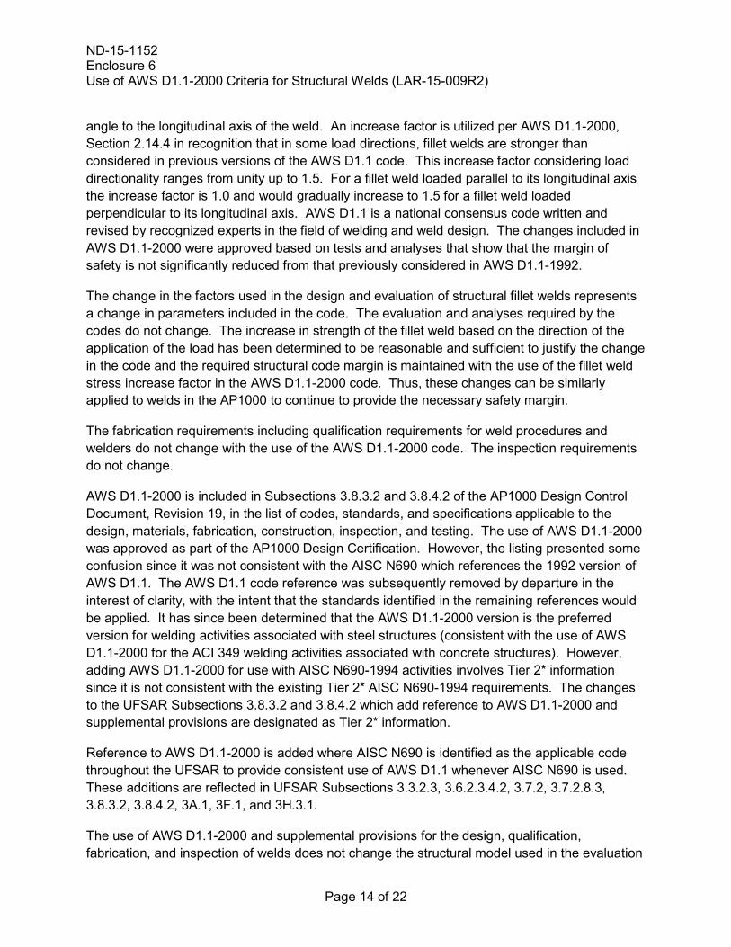
angle to the longitudinal axis of the weld. An increase factor is utilized per AWS D1.1-2000, Section 2.14.4 in recognition that in some load directions, fillet welds are stronger than considered in previous versions of the AWS D1.1 code. This increase factor considering load directionality ranges from unity up to 1.5. For a fillet weld loaded parallel to its longitudinal axis the increase factor is 1.0 and would gradually increase to 1.5 for a fillet weld loaded perpendicular to its longitudinal axis. AWS D1.1 is a national consensus code written and revised by recognized experts in the field of welding and weld design. The changes included in AWS D1.1-2000 were approved based on tests and analyses that show that the margin of safety is not significantly reduced from that previously considered in AWS D1.1-1992.
The change in the factors used in the design and evaluation of structural fillet welds represents a change in parameters included in the code. The evaluation and analyses required by the codes do not change. The increase in strength of the fillet weld based on the direction of the application of the load has been determined to be reasonable and sufficient to justify the change in the code and the required structural code margin is maintained with the use of the fillet weld stress increase factor in the AWS D1.1-2000 code. Thus, these changes can be similarly applied to welds in the AP1000 to continue to provide the necessary safety margin.
The fabrication requirements including qualification requirements for weld procedures and welders do not change with the use of the AWS D1.1-2000 code. The inspection requirements do not change.
AWS D1.1-2000 is included in Subsections 3.8.3.2 and 3.8.4.2 of the AP1000 Design Control Document, Revision 19, in the list of codes, standards, and specifications applicable to the design, materials, fabrication, construction, inspection, and testing. The use of AWS D1.1-2000 was approved as part of the AP1000 Design Certification. However, the listing presented some confusion since it was not consistent with the AISC N690 which references the 1992 version of AWS D1.1. The AWS D1.1 code reference was subsequently removed by departure in the interest of clarity, with the intent that the standards identified in the remaining references would be applied. It has since been determined that the AWS D1.1-2000 version is the preferred version for welding activities associated with steel structures (consistent with the use of AWS D1.1-2000 for the ACI 349 welding activities associated with concrete structures). However, adding AWS D1.1-2000 for use with AISC N690-1994 activities involves Tier 2* information since it is not consistent with the existing Tier 2* AISC N690-1994 requirements. The changes to the UFSAR Subsections 3.8.3.2 and 3.8.4.2 which add reference to AWS D1.1-2000 and supplemental provisions are designated as Tier 2* information.
Reference to AWS D1.1-2000 is added where AISC N690 is identified as the applicable code throughout the UFSAR to provide consistent use of AWS D1.1 whenever AISC N690 is used. These additions are reflected in UFSAR Subsections 3.3.2.3, 3.6.2.3.4.2, 3.7.2, 3.7.2.8.3, 3.8.3.2, 3.8.4.2, 3A.1, 3F.1, and 3H.3.1.
The use of AWS D1.1-2000 and supplemental provisions for the design, qualification, fabrication, and inspection of welds does not change the structural model used in the evaluation
ND-15-1152 Enclosure 6 Use of AWS D1.1-2000 Criteria for Structural Welds (LAR-15-009R2)
Page 15 of 22
of the nuclear island structures. The evaluation method for the seismic and structural evaluation of the nuclear island structures and the seismic Category II portions of the annex building and turbine building is not changed. The design of the nuclear island structures using AWS D1.1-2000 and supplemental provisions for the design, qualification, fabrication, and inspection of welds is in conformance with the applicable portions of ACI 349, the remaining applicable portions of AISC N690 not related to requirements for welding, including the supplemental requirements described in UFSAR Subsections 3.8.4.4.1 and 3.8.4.5, and the supplemental requirements identified in UFSAR Subsection 3.8.3 for structural modules. The design of the seismic Category II portions of the annex building and turbine building using AWS D1.1-2000 and supplemental provisions for welding is in conformance with the applicable portions of ACI 349 and the remaining applicable portions of AISC N690.
The proposed changes do not change the function, design, or operation of the systems and components supported by the walls, floors, floor modules and structural wall modules. The proposed changes do not change the function, design, or operation of the safety related systems and components. The proposed changes do not affect the prevention or mitigation of abnormal events (e.g., accidents, anticipated operational occurrences, earthquakes, floods and turbine missiles, or their safety or design analyses). The proposed changes do not involve, nor interface with, any structure, system or component accident initiator or initiating sequence of events, and thus, the probabilities of the accidents previously evaluated in the plant-specific DCD or UFSAR are not affected.
The proposed changes do not make changes to or affect safety-related equipment or a fission product barrier. No system or design function or equipment qualification would be adversely affected by the proposed changes. The changes do not result in a new failure mode, malfunction or sequence of events that could adversely affect a radioactive material barrier or safety-related equipment. The proposed changes do not allow for a new fission product release path, result in a new fission product barrier failure mode, or create a new sequence of events that would result in significant fuel cladding failures.
The proposed changes do not adversely affect any safety-related system, component, or equipment, design code, design code allowable value, function or design analysis, nor do they adversely affect any safety analysis input or result, or design/safety margin.
The proposed activity has no adverse effect on the ex-vessel severe accident. The design, geometry, and strength of the containment internal structures are not changed. The design and material selection of the concrete floor beneath the reactor vessel is not altered. The response of the containment to a postulated reactor vessel failure, including direct containment heating, ex-vessel steam explosions, and core concrete interactions is not altered by the changes to the detail design of welds. The design of the reactor vessel and the response of the reactor vessel to a postulated severe accident are not altered by the changes to the detail design of welds.
The proposed activity has no impact on the Aircraft Impact Assessment. The changes described are internal to the structures and do not impact the design or response of the
ND-15-1152 Enclosure 6 Use of AWS D1.1-2000 Criteria for Structural Welds (LAR-15-009R2)
Page 16 of 22
containment vessel and shield building. There is no change to protection of plant structures, systems, and components against aircraft impact provided by the design of the shield building. There is no change to the design of any of the key design features described in UFSAR Appendix 19F. The activity described does not change the overall design or construction of the shield building.
The proposed changes associated with this license amendment request provide for the use of AWS D1.1-2000 and supplemental provisions to provide criteria for the design, qualification, fabrication, and inspection of welds for nuclear island structures and the seismic Category II portions of the annex building and turbine building. The changes are internal to the structures and the configuration, thickness, and density of the structures are not changed. The proposed changes do not affect the radiological source terms (i.e., amounts and types of radioactive materials released, their release rates and release durations) used in the accident analyses, thus, the consequences of accidents are not affected. These changes do not affect the containment, control, channeling, monitoring, processing or releasing of radioactive and non-radioactive materials. The location and design of penetrations and the permeability of the concrete structures is not changed. No effluent release path is affected. The types and quantities of expected effluents are not changed. The functionality of the design and operational features that are credited with controlling the release of effluents during plant operation is not diminished. Therefore, neither radioactive nor non-radioactive material effluents are affected.
The thickness of the walls, floors, structural modules and floor modules and the density of the concrete are not changed; therefore, there is no adverse change to the shielding provided by the floors, walls, structural modules and floor modules. There is no change to plant systems or the response of systems to postulated accident conditions. There is no change to the predicted radioactive releases due to normal operation or postulated accident conditions. Plant radiation zones, controls under 10 CFR Part 20, and expected amounts and types of radiologically controlled materials are not affected by the proposed changes. Therefore, individual and cumulative radiation exposures do not change.
The change activity has no impact on the emergency plans or the physical security evaluation since there are no changes to the external configuration of walls, doors, or access to the Nuclear Island.
Summary
The proposed changes would revise the requirements for welding for seismic Category I and seismic Category II structures. The changes involve Tier 2* requirements for the seismic Category I and seismic Category II structures. This activity changes the requirements for welds in nuclear island structures and the seismic Category II portions of the turbine building and annex building. The design change incorporates criteria of American Welding Society (AWS) D1.1-2000 into the design, qualification, fabrication, and inspection of structures for
ND-15-1152 Enclosure 6 Use of AWS D1.1-2000 Criteria for Structural Welds (LAR-15-009R2)
Page 17 of 22
which the provisions of American Institute of Steel Construction (AISC) N690-1994 are applicable. The changes to the UFSAR that permit the use of provisions in AWS D1.1-2000 for the application of directionality are supplemented with additional provisions for linear weld groups concentrically loaded in the plane of the weld and consisting of elements oriented both longitudinally and transversely to the direction of the applied load. The changes also specify extension of the application of directionality provisions to linear and concentrically loaded (i.e., loaded through the center of gravity of the weld group) rectangular and circular fillet weld groups loaded out-of-plane to the axis of the weld to supplement the conditions specified in AWS D1.1. The proposed changes do not adversely affect the strength or response of the nuclear island seismic Category I structures or seismic Category II structures.
The above proposed changes do not adversely affect any safety-related equipment or function, design function, radioactive material barrier or safety analysis.
4. Regulatory Evaluation
4.1 Applicable Regulatory Requirements/Criteria
10 CFR Part 52, Appendix D, VIII.B.6 and VIII.B.5.a, require prior NRC approval for departure from Tier 2* information and for Tier 2 information departures that involve changes to Tier 2* information, respectively. The proposed amendment includes the use of AWS D1.1-2000 and supplemental provisions to provide criteria for the design, qualification, fabrication, and inspection of welds for nuclear island structures and the seismic Category II portions of the annex building and turbine building. This change specifies the use of AWS D1.1-2000 and supplemental provisions in lieu of AWS D1.1-1992 as identified in the AISC N690-1994 code, which is designated as a Tier 2* requirement for the design, qualification, fabrication, and inspection of these structures. Therefore, this change involves UFSAR Tier 2* information and a license amendment request (LAR) (as supplied herein) is required.
10 CFR Part 50, Appendix A, General Design Criterion (GDC) 1 requires that structures be designed, fabricated, erected, constructed, tested, and inspected to quality standards commensurate with the importance of the safety functions to be performed. The proposed change does not change the criteria for the design, analysis, and construction of the nuclear island structures and the seismic Category II portions of the annex building and turbine building except for those changes noted for welding. These structures remain in conformance with the code requirements identified and supplemented in the UFSAR; i.e., applicable portions of ACI 349, the remaining applicable portions of AISC N690, including the supplemental requirements described in UFSAR Subsections 3.8.4.4.1 and 3.8.4.5, and the supplemental requirements identified in the UFSAR Subsection 3.8.3 for structural modules.
10 CFR Part 50, Appendix A, GDC 2 requires that structures withstand the effects of earthquakes and appropriate combinations of the effects of normal and accident conditions, including the effects of environmental loadings, such as earthquakes and other natural
ND-15-1152 Enclosure 6 Use of AWS D1.1-2000 Criteria for Structural Welds (LAR-15-009R2)
Page 18 of 22
phenomena. The proposed changes have no impact on the seismic motions to which the nuclear island structures are subjected and no impact on the response of the nuclear island structures to seismic motions.
10 CFR Part 50, Appendix A, GDC 4 requires that systems structures and components can withstand the dynamic effects associated with missiles, pipe whipping, and discharging fluids, excluding dynamic effects associated with pipe ruptures, the probability of which is extremely low under conditions consistent with the design basis for the piping. The proposed changes do not change the configuration of the walls and floors which provide separation between sources and potential targets. The proposed changes have no impact on the capability of the systems, structures, and components to withstand dynamic effects associated with missiles, pipe whipping, and discharging fluids as required by this criterion. The proposed changes do not change the requirements for anchoring safety related components and supports to seismic Category I structures.
4.2 Precedent
No precedent is identified.
4.3 Significant Hazards Consideration Determination
The proposed amendment would revise the plant-specific Design Control Document (DCD) Tier 2 and involved Tier 2* material incorporated into the Updated Final Safety Analysis Report (UFSAR), by revising the requirement to utilize American Welding Society (AWS) D1.1-1992, Structural Welding Code - Steel, when meeting the American Institute of Steel Construction (AISC) N690-1994 requirements. The changes involve the replacement of AWS D1.1-1992 with AWS D1.1-2000 and additional supplemental provisions consistent with provisions in AWS D1.1-2010 to provide criteria for AISC N690 activities related to the design, qualification, fabrication, and inspection of welds for nuclear island structures and the seismic Category II portions of the annex building and turbine building.
An evaluation to determine whether or not a significant hazards consideration is involved with the proposed amendment was completed by focusing on the three standards set forth in 10 CFR 50.92, “Issuance of amendment,” as discussed below:
4.3.1 Does the proposed amendment involve a significant increase in the probability or consequences of an accident previously evaluated?
Response: No
The design functions of the nuclear island structures are to provide support, protection, and separation for the seismic Category I mechanical and electrical equipment located in the nuclear island. The nuclear island structures are structurally designed to meet seismic Category I requirements as defined in
ND-15-1152 Enclosure 6 Use of AWS D1.1-2000 Criteria for Structural Welds (LAR-15-009R2)
Page 19 of 22
Regulatory Guide 1.29. The design functions of the seismic Category II portions of the annex building and turbine building are to provide integrity for non-seismic items located in the proximity of safety-related items, the failure of which during a safe shutdown earthquake could result in loss of function of safety-related items.
The use of AWS D1.1-2000 and the supplemental provisions provide criteria for the design, qualification, fabrication, and inspection of welds for nuclear island structures and seismic Category II portions of the annex building and turbine building. These structures continue to meet the applicable portions of ACI 349, the remaining applicable portions of AISC N690 not related to requirements for welding, including the supplemental requirements described in UFSAR Subsections 3.8.4.4.1 and 3.8.4.5, and the supplemental requirements identified in UFSAR Subsection 3.8.3 for structural modules. The use of AWS D1.1-2000 and the supplemental provisions does not have an adverse impact on the response of the nuclear island structures, or seismic Category II portions of the annex building and turbine building to safe shutdown earthquake ground motions or loads due to anticipated transients or postulated accident conditions. The change does not impact the support, design, or operation of mechanical and fluid systems. There is no change to plant systems or the response of systems to postulated accident conditions. There is no change to the predicted radioactive releases due to normal operation or postulated accident conditions. The plant response to previously evaluated accidents or external events is not adversely affected, nor does the change described create any new accident precursors.
Therefore, the proposed amendment does not involve a significant increase in the probability or consequences of an accident previously evaluated.
4.3.2 Does the proposed amendment create the possibility of a new or different kind of accident from any accident previously evaluated?
Response: No
The proposed change includes the use of AWS D1.1-2000 and supplemental provisions to provide criteria for the design, qualification, fabrication, and inspection of welds for nuclear island structures and the seismic Category II portions of the annex building and turbine building. The proposed change provides a consistent set of requirements for welding of structures required to be designed to the requirements of ACI 349 and AISC N690. The change to the details does not change the design function, support, design, or operation of mechanical and fluid systems. The change to the welding criteria does not result in a new failure mechanism for the pertinent structures or new accident precursors. As a result, the design function of the structures is not adversely affected by the proposed change.

ND-15-1152 Enclosure 6 Use of AWS D1.1-2000 Criteria for Structural Welds (LAR-15-009R2)
Page 20 of 22
Therefore, the proposed amendment does not create the possibility of a new or different kind of accident from any accident previously evaluated.
4.3.3 Does the proposed amendment involve a significant reduction in a margin of safety?
Response: No
The AWS codes are consensus standards written, revised, and approved by industry experts experienced in welding and weld design. The proposed change adds AWS D1.1-2000 to the list of applicable codes and standards in the UFSAR and adds supplemental provisions consistent with AWS D1.1-2010. The 2000 edition includes criteria that consider directionality in the weld, which allows for an increase factor on structural fillet weld strength relative to the angle of load direction. Supplemental provisions are added to the provisions in AWS D1.1-2000 for the application of directionality for linear fillet weld groups concentrically loaded in-plane to the axis of the weld that include elements oriented both longitudinally and transversely to the direction of applied load to address deformation of the welds. The change also specifies extension of the application of directionality provisions to linear and concentrically loaded rectangular and circular fillet weld groups loaded out-of-plane to the axis of the weld to supplement the conditions specified in AWS D1.1. These changes are supported by tests that provide the justification for criteria that consider the directionality. These changes can be similarly applied to welds in the AP1000 to continue to provide the necessary safety margin.
Therefore, the proposed amendment does not involve a significant reduction in a margin of safety.
Based on the above, it is concluded that the proposed amendment does not involve a significant hazards consideration under the standards set forth in 10 CFR 50.92(c), and, accordingly, a finding of “no significant hazards consideration” is justified.
4.4 Conclusions
Based on the considerations discussed above, (1) there is reasonable assurance that the health and safety of the public will not be endangered by operation in the proposed manner, (2) such activities will be conducted in compliance with the Commission’s regulations, and (3) the issuance of the amendment will not be inimical to the common defense and security or to the health and safety of the public.
ND-15-1152 Enclosure 6 Use of AWS D1.1-2000 Criteria for Structural Welds (LAR-15-009R2)
Page 21 of 22
5. Environmental Considerations
The proposed amendment revises plant-specific Design Control Document (DCD) Tier 2 and involved Tier 2* material incorporated into the Updated Final Safety Analysis Report (UFSAR), through the use of AWS D1.1-2000 and supplemental provisions to provide consistent criteria for the design and evaluation of welding for selected structural design elements in the nuclear island structures and seismic Category II portions of the annex building and turbine building.
A review has determined that the proposed amendment would change a requirement with respect to installation or use of a facility component located within the restricted area, as defined in 10 CFR Part 20, or would change an inspection or surveillance requirement. However, facility construction and operation following implementation of the proposed amendment does not involve (i) a significant hazards consideration, (ii) a significant change in the types or a significant increase in the amounts of any effluents that may be released offsite, or (iii) a significant increase in individual or cumulative occupational radiation exposure. Accordingly, the proposed amendment meets the eligibility criteria for categorical exclusion set forth in 10 CFR 51.22(c)(9), in that:
(i) There is no significant hazards consideration.
As documented in Section 4.3, Significant Hazards Consideration Determination, of this license amendment request, an evaluation was completed to determine whether or not a significant hazards consideration is involved by focusing on the three standards set forth in 10 CFR 50.92, “Issuance of amendment.” The Significant Hazards Consideration determined that (1) the proposed amendment does not involve a significant increase in the probability or consequences of an accident previously evaluated; (2) the proposed amendment does not create the possibility of a new or different kind of accident from any accident previously evaluated; and (3) the proposed amendment does not involve a significant reduction in a margin of safety. Therefore, it is concluded that the proposed amendment does not involve a significant hazards consideration under the standards set forth in 10 CFR 50.92(c), and accordingly, a finding of “no significant hazards consideration” is justified.
(ii) There is no significant change in the types or significant increase in the amounts of any effluents that may be released offsite.
The proposed amendment involves changes unrelated to any aspect of plant construction or operation that would introduce any change to effluent types (e.g., effluents containing chemicals or biocides, sanitary system effluents, and other effluents), or affect any plant radiological or non-radiological effluent release quantities. Furthermore, the proposed changes do not affect any effluent release path or diminish the functionality of any design or operational features that are credited with controlling the release of effluents during plant operation. Therefore, it is concluded that the
ND-15-1152 Enclosure 6 Use of AWS D1.1-2000 Criteria for Structural Welds (LAR-15-009R2)
Page 22 of 22
proposed amendment does not involve a significant change in the types or a significant increase in the amounts of any effluents that may be released offsite.
(iii) There is no significant increase in individual or cumulative occupational radiation exposure.
The proposed amendment involves changes to the design details for welds related to AISC N690 activities for seismic Category I and II structures, systems, and components but, does not impact shielding. Plant radiation zones are not affected, nor are there any changes to the controls required under 10 CFR Part 20 that preclude a significant increase in occupational radiation exposure. Consequently, these changes have no effect on individual or cumulative occupational radiation exposure during plant operation. Therefore, it is concluded that the proposed amendment does not involve a significant increase in individual or cumulative occupational radiation exposure.
Based on the above review of the proposed amendment, it has been determined that anticipated construction and operational impacts of the proposed amendment do not involve (i) a significant hazards consideration, (ii) a significant change in the types or significant increase in the amounts of any effluents that may be released offsite, or (iii) a significant increase in the individual or cumulative occupational radiation exposure. Accordingly, the proposed amendment meets the eligibility criteria for categorical exclusion set forth in 10 CFR 51.22(c)(9). Therefore, pursuant to 10 CFR 51.22(b), no environmental impact statement or environmental assessment need be prepared in connection with the proposed amendment.
6. References
Higgens and Preece, 1969
https://www.aisc.org/store/p-296-proposed-working-stresses-for-fillet-welds-in-building-construction.aspx
Gomez et al, 2008
http://www.aisc.org/uploadedFiles/Research/Research_Reports/Kanvinde%20-%20Out%20of%20Plane%20Bending%20Welds.pdf
Ng et al, 2004
https://www.aisc.org/store/p-1105-behavior-of-transverse-fillet-welds-experimental-program.aspx
Southern Nuclear Operating Company
Vogtle Electric Generating Plant (VEGP) Units 3 and 4
ND-15-1152
Enclosure 7
Revised Proposed Changes to Licensing Basis Documents
(LAR-15-009R2)
(This Enclosure consists of 6 pages, including this cover page)
ND-15-1152 Enclosure 7 Revised Proposed Changes to Licensing Basis Documents (LAR-15-009R2)
Page 2 of 6
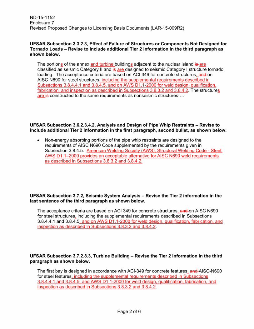
UFSAR Subsection 3.3.2.3, Effect of Failure of Structures or Components Not Designed for Tornado Loads – Revise to include additional Tier 2 information in the third paragraph as shown below.
The portions of the annex and turbine buildings adjacent to the nuclear island is are classified as seismic Category II and is are designed to seismic Category I structure tornado loading. The acceptance criteria are based on ACI 349 for concrete structures, and on AISC N690 for steel structures, including the supplemental requirements described in Subsections 3.8.4.4.1 and 3.8.4.5, and on AWS D1.1-2000 for weld design, qualification, fabrication, and inspection as described in Subsections 3.8.3.2 and 3.8.4.2. The structures are is constructed to the same requirements as nonseismic structures….
UFSAR Subsection 3.6.2.3.4.2, Analysis and Design of Pipe Whip Restraints – Revise to include additional Tier 2 information in the first paragraph, second bullet, as shown below.
• Non-energy absorbing portions of the pipe whip restraints are designed to the requirements of AISC N690 Code supplemented by the requirements given in Subsection 3.8.4.5. American Welding Society (AWS), Structural Welding Code - Steel, AWS D1.1–2000 provides an acceptable alternative for AISC N690 weld requirements as described in Subsections 3.8.3.2 and 3.8.4.2.
UFSAR Subsection 3.7.2, Seismic System Analysis – Revise the Tier 2 information in the last sentence of the third paragraph as shown below.
The acceptance criteria are based on ACI 349 for concrete structures, and on AISC N690 for steel structures, including the supplemental requirements described in Subsections 3.8.4.4.1 and 3.8.4.5, and on AWS D1.1-2000 for weld design, qualification, fabrication, and inspection as described in Subsections 3.8.3.2 and 3.8.4.2.
UFSAR Subsection 3.7.2.8.3, Turbine Building – Revise the Tier 2 information in the third paragraph as shown below.
The first bay is designed in accordance with ACI-349 for concrete features, and AISC-N690 for steel features, including the supplemental requirements described in Subsections 3.8.4.4.1 and 3.8.4.5, and AWS D1.1-2000 for weld design, qualification, fabrication, and inspection as described in Subsections 3.8.3.2 and 3.8.4.2.
ND-15-1152 Enclosure 7 Revised Proposed Changes to Licensing Basis Documents (LAR-15-009R2)
Page 3 of 6
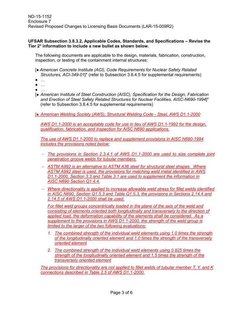
UFSAR Subsection 3.8.3.2, Applicable Codes, Standards, and Specifications – Revise the Tier 2* information to include a new bullet as shown below.
The following documents are applicable to the design, materials, fabrication, construction, inspection, or testing of the containment internal structures:
[ American Concrete Institute (ACI), Code Requirements for Nuclear Safety Related Structures, ACI-349-01]* (refer to Subsection 3.8.4.5 for supplemental requirements)
… … … [ American Institute of Steel Construction (AISC), Specification for the Design, Fabrication
and Erection of Steel Safety Related Structures for Nuclear Facilities, AISC-N690-1994]* (refer to Subsection 3.8.4.5 for supplemental requirements)
[ American Welding Society (AWS), Structural Welding Code - Steel, AWS D1.1-2000
AWS D1.1-2000 is an acceptable code for use in lieu of AWS D1.1-1992 for the design, qualification, fabrication, and inspection for AISC N690 applications.
The use of AWS D1.1-2000 to replace and supplement provisions in AISC N690-1994
includes the provisions noted below:
− The provisions in Section 2.3.4.1 of AWS D1.1-2000 are used to size complete joint penetration groove welds for tubular members.
− ASTM A992 is an alternative to ASTM A36 steel for structural steel shapes. Where ASTM A992 steel is used, the provisions for matching weld metal identified in AWS D1.1-2000, Section 3.3 and Table 3.1 are used to supplement the information in AISC N690 Section Q1.4.4.
− Where directionality is applied to increase allowable weld stress for fillet welds identified in AISC N690, Section Q1.5.3 and Table Q1.5.3, the provisions in Sections 2.14.4 and 2.14.5 of AWS D1.1-2000 shall be used.
For fillet weld groups concentrically loaded in the plane of the axis of the weld and consisting of elements oriented both longitudinally and transversely to the direction of applied load, the deformation capability of the elements shall be considered. As a supplement to the provisions in AWS D1.1-2000, the strength of the weld group is limited to the larger of the two following evaluations:
1. The combined strength of the individual weld elements using 1.0 times the strength of the longitudinally oriented element and 1.0 times the strength of the transversely oriented element
2. The combined strength of the individual weld elements using 0.825 times the strength of the longitudinally oriented element and 1.5 times the strength of the transversely oriented element
The provisions for directionality are not applied to fillet welds of tubular member T, Y, and K connections described in Table 2.5 of AWS D1.1-2000.
ND-15-1152 Enclosure 7 Revised Proposed Changes to Licensing Basis Documents (LAR-15-009R2)
Page 4 of 6
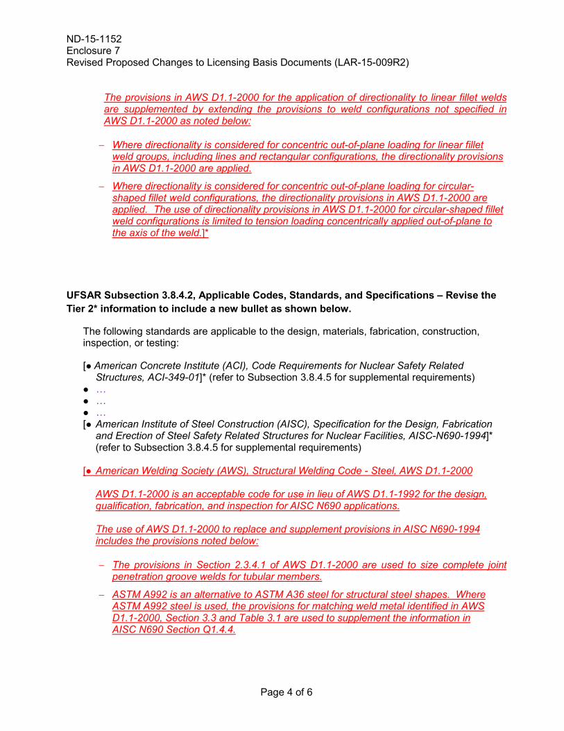
The provisions in AWS D1.1-2000 for the application of directionality to linear fillet welds are supplemented by extending the provisions to weld configurations not specified in AWS D1.1-2000 as noted below:
− Where directionality is considered for concentric out-of-plane loading for linear fillet
weld groups, including lines and rectangular configurations, the directionality provisions in AWS D1.1-2000 are applied.
− Where directionality is considered for concentric out-of-plane loading for circular-shaped fillet weld configurations, the directionality provisions in AWS D1.1-2000 are applied. The use of directionality provisions in AWS D1.1-2000 for circular-shaped fillet weld configurations is limited to tension loading concentrically applied out-of-plane to the axis of the weld.]*
UFSAR Subsection 3.8.4.2, Applicable Codes, Standards, and Specifications – Revise the Tier 2* information to include a new bullet as shown below.
The following standards are applicable to the design, materials, fabrication, construction, inspection, or testing:
[ American Concrete Institute (ACI), Code Requirements for Nuclear Safety Related Structures, ACI-349-01]* (refer to Subsection 3.8.4.5 for supplemental requirements)
… … … [ American Institute of Steel Construction (AISC), Specification for the Design, Fabrication
and Erection of Steel Safety Related Structures for Nuclear Facilities, AISC-N690-1994]* (refer to Subsection 3.8.4.5 for supplemental requirements)
[ American Welding Society (AWS), Structural Welding Code - Steel, AWS D1.1-2000
AWS D1.1-2000 is an acceptable code for use in lieu of AWS D1.1-1992 for the design, qualification, fabrication, and inspection for AISC N690 applications.
The use of AWS D1.1-2000 to replace and supplement provisions in AISC N690-1994
includes the provisions noted below:
− The provisions in Section 2.3.4.1 of AWS D1.1-2000 are used to size complete joint penetration groove welds for tubular members.
− ASTM A992 is an alternative to ASTM A36 steel for structural steel shapes. Where ASTM A992 steel is used, the provisions for matching weld metal identified in AWS D1.1-2000, Section 3.3 and Table 3.1 are used to supplement the information in AISC N690 Section Q1.4.4.
ND-15-1152 Enclosure 7 Revised Proposed Changes to Licensing Basis Documents (LAR-15-009R2)
Page 5 of 6
− Where directionality is applied to increase allowable weld stress for fillet welds identified in AISC N690, Section Q1.5.3 and Table Q1.5.3, the provisions in Sections 2.14.4 and 2.14.5 of AWS D1.1-2000 shall be used.
For fillet weld groups concentrically loaded in the plane of the axis of the weld and consisting of elements oriented both longitudinally and transversely to the direction of applied load, the deformation capability of the elements shall be considered. As a supplement to the provisions in AWS D1.1-2000, the strength of the weld group is limited to the larger of the two following evaluations:
1. The combined strength of the individual weld elements using 1.0 times the strength of the longitudinally oriented element and 1.0 times the strength of the transversely oriented element
2. The combined strength of the individual weld elements using 0.825 times the strength of the longitudinally oriented element and 1.5 times the strength of the transversely oriented element
The provisions for directionality are not applied to fillet welds of tubular member T, Y, and K connections described in Table 2.5 of AWS D1.1-2000.
The provisions in AWS D1.1-2000 for the application of directionality to linear fillet welds are supplemented by extending the provisions to weld configurations not specified in AWS D1.1-2000 as noted below:
− Where directionality is considered for concentric out-of-plane loading for linear fillet
weld groups, including lines and rectangular configurations, the directionality provisions in AWS D1.1-2000 are applied.
− Where directionality is considered for concentric out-of-plane loading for circular-shaped fillet weld configurations, the directionality provisions in AWS D1.1-2000 are applied. The use of directionality provisions in AWS D1.1-2000 for circular-shaped fillet weld configurations is limited to tension loading concentrically applied out-of-plane to the axis of the weld.]*
ND-15-1152 Enclosure 7 Revised Proposed Changes to Licensing Basis Documents (LAR-15-009R2)
Page 6 of 6
UFSAR Subsection 3A.1, Codes and Standards – Revise Tier 2 bullet to include new information as shown below.
The design of the HVAC ducts and their supports conform to the following codes and standards:
… … American Institute of Steel Construction (AISC), Specification for the Design, Fabrication
and Erection of Steel Safety Related Structures for Nuclear Facilities, AISC-N690-1994. American Welding Society (AWS), Structural Welding Code - Steel, AWS D1.1-2000 provides an acceptable alternative for AISC N690 for weld requirements as described in Subsections 3.8.3.2 and 3.8.4.2.
…
UFSAR Subsection 3F.1, Codes and Standards – Revise Tier 2 bullet to include new information as shown below.
The design of cable trays and their supports conform to the following codes and standards:
… American Institute of Steel Construction (AISC), Specification for the Design, Fabrication
and Erection of Steel Safety Related Structures for Nuclear Facilities, AISC-N690-1994. American Welding Society (AWS), Structural Welding Code - Steel, AWS D1.1-2000
provides an acceptable alternative for AISC N690 weld requirements as described in Subsections 3.8.3.2 and 3.8.4.2.
…
UFSAR Subsection 3H.3.1, Governing Codes and Standards – Revise Tier 2* bullet to include new information as shown below.
[The primary codes and standards used in the design of the auxiliary and shield buildings are listed below:
ACI 349-01, "Code Requirement for Nuclear Safety-Related Structure Steel" (refer to Subsection 3.8.4.5 for supplementary requirements and Subsection 3.8.4.4.1 for alternative requirements).
ANSI/AISC N690-1994, "Specification for the Design, Fabrication and Erection of Safety-
Related Steel Structures for Nuclear Facilities" (refer to subsection 3.8.4.5 for supplemental requirements). American Welding Society (AWS), Structural Welding Code - Steel, AWS D1.1-2000 provides an acceptable alternative for AISC N690 weld requirements as described in Subsections 3.8.3.2 and 3.8.4.2.]*