Embed Size (px)
Citation preview

ARTICLE
International Journal of Advanced Robotic Systems
A Comparison Study on Motion/ForceTransmissibility of Two Typical 3-DOFParallel Manipulators: The Sprint Z3 andA3 Tool HeadsRegular Paper
Xiang Chen1,2, Xin-Jun Liu1,2*, FuGui Xie1,2 and Tao Sun3
1 State Key Laboratory of Tribology & Institute of Manufacturing Engineering, Department of Mechanical Engineering, Tsinghua University,Beijing, PR China
2 Beijing Key Lab of Precision/Ultra-precision Manufacturing Equipment and Control, Tsinghua University, Beijing, China3 School of Mechanical Engineering, Tianjin University, Tianjin, China*Corresponding author(s) E-mail: [email protected]
Received 10 January 2013; Accepted 28 November 2013
DOI: 10.5772/57458
© 2014 The Author(s). Licensee InTech. This is an open access article distributed under the terms of the Creative Commons Attribution License(http://creativecommons.org/licenses/by/3.0), which permits unrestricted use, distribution, and reproduction in any medium, provided theoriginal work is properly cited.
Abstract
This paper presents a comparison study of two importantthree-degree-of-freedom (DOF) parallel manipulators, theSprint Z3 head and the A3 head, both commonly used inindustry. As an initial step, the inverse kinematics arederived and an analysis of two classes of limbs is carriedout via screw theory. For comparison, three transmissionindices are then defined to describe their motion/forcetransmission performance. Based on the same mainparameters, the compared results reveal some distinctcharacteristics in addition to the similarities between thetwo parallel manipulators. To a certain extent, the A3 headoutperforms the common Sprint Z3 head, providing a newand satisfactory option for a machine tool head in industry.
Keywords Parallel Manipulators, Sprint Z3 Head, A3Head, Comparison, Motion/Force Transmissibility
1. Introduction
In theory, parallel manipulators are capable of answeringthe increasing industrial need for high stiffness, compact‐ness, load-to-weight ratio, accuracy, etc. For this reason,parallel manipulators are preferable to serial ones in someapplications. In general, a parallel manipulator consists ofa moving platform that is connected to a fixed base bymeans of several limbs.
There has been extensive attention given to parallelmanipulators since Stewart developed the Gough-Stewartplatform [1] for use as an aircraft simulator [2]. A wealth ofresearch has been published on six-degree-of-freedom(DOF) Stewart-like parallel manipulators, and researchershave come to realize their limitations due to complex directkinematics, unsatisfactory workspace, and poor orienta‐tion capability [3]. However, it is possible for so-calleddefective parallel manipulators with fewer than six DOFsto overcome these disadvantages while retaining theadvantages of parallel manipulators [4]. A significant
1Int J Adv Robot Syst, 2014, 11:0 | doi: 10.5772/57458

amount of research has recently been devoted to low-mobility parallel manipulators. In fact, most of the parallelmanipulators used successfully in industrial applicationsbelong to the low-mobility category. Examples of suchcases are the Delta [5], Tricept [6], Exechon [7], and SprintZ3 heads [8], among others. Especially in thin-wall ma‐chining applications for structural aluminium aerospacecomponents, the emergence of the Sprint Z3 tool head(Figure 1) produced by the DS Technologie Company inGermany [8] has attracted widespread attention from themachine tool user community. Many advantages of theSprint Z3 head have been shown, including high speed,high rigidity, good dexterity, and large orientation capa‐bility [9, 10]. Inspired by the prototype of the Sprint Z3head, a new tool head named A3 (Figure 2), generating thesame DOFs as the Sprint Z3 head, i.e., 1T2R DOFs (onetranslation and two rotations), was developed by Huang etal. [11] at Tianjin University, China.
Both the Sprint Z3 and the A3 heads are so-called 3-[PP]Sparallel mechanisms, defined as mechanisms whose threespherical joints move in vertical planes intersecting at acommon line [12]. Such manipulators are referred to aszero-torsion mechanisms. Due to their similarities intopological configuration, they have some properties incommon. However, as architectures of industrial proto‐types there is some variation. Thus, it is necessary andreasonable to obtain a better understanding of this type ofparallel manipulator by studying the similarities anddifferences to facilitate better use of these tool heads inindustry.
To date, many research activities have concentrated on thedevelopment of high-rigidity and good-dexterity heavy-duty tool heads comprising 3-DOF parallel manipulatorsin application. Significant efforts have been directedtowards analysing the Sprint Z3 and A3 heads, includinginverse and direct kinematic analyses, dynamic analysis,and analysis of workspaces and orientation capabilities[13-16]. However, as far as the authors are aware, there hasnot yet been published a systematic comparison of the twoparallel manipulators. In addition, no existing literatureconsiders their performance in terms of the motion/forcetransmission capabilities, despite the well-known fact thatthe key function of a parallel manipulator is to transmitmotion/force between its input members and outputmembers.
This paper supplements previous efforts with regard tomotion/force transmissibility analysis based on the theoryof screws, and subsequently concentrates on the compari‐son of the two 3-DOF parallel manipulators commonlyused in industry [17]. The transmission performance atlasesare illustrated based on three proposed transmissionindices to depict the similarities and distinctions betweenthe two parallel manipulators. In addition, the goodtransmission workspaces are correspondingly presentedfor comparison purposes when the same main parametersare given.
Figure 1. Model of Sprint Z3 head [8]
Figure 2. CAD model of A3 head
The rest of this paper is arranged as follows. The mecha‐nisms of the Sprint Z3 head and the A3 head are describedand their inverse kinematics equations are derived inSection 2. In Section 3, a motion/force transmission analysisusing three indices based on screw theory is presented. Thecompared results of the motion/force transmission per‐formance for the Sprint Z3 head and the A3 head are shownin Section 4. Finally, the development of the A3 tool headand some conclusions are discussed in Section 5 andSection 6, respectively.
2. Structure description and kinematic analysis
2.1 Structure description
Both the Sprint Z3 head and the A3 head have three DOFs,in terms of one translation and two rotations, which thenproduce other parasitic motions. They can realize thefunction of serial A/B-axis tool heads and the linkedmovement of the two rotational DOFs. In general, boththese parallel tool heads are designed to implement high-speed five-axis milling applications by combining thehead’s three DOFs with another two translational DOFs,
2 Int J Adv Robot Syst, 2014, 11:0 | doi: 10.5772/57458

thereby generating a large translational workspace with thehybrid architecture.
The architecture behind the Sprint Z3 head is a 3-PRSparallel kinematic mechanism (Figure 3). The movingplatform is connected to a fixed base with three identicallimbs. Each limb consists of a prismatic joint (P), a revolutejoint (R) and a spherical joint (S) in series, connecting thefixed base to the moving platform. The P joint is actuated.All the joints connected to the base and mobile platform aresymmetrically distributed at vertices of the equilateraltriangles.
Figure 3. Schematics of 3-PRS parallel manipulator
The schematic diagram given in Figure 4 is a well-known3-RPS parallel mechanism, which is exactly the architecturebehind the A3 tool head. The moving platform is symmet‐rically connected to a base with three identical limbs. Eachlimb consists of a revolute joint (R), an actuated prismaticjoint (P), and a spherical joint (S) in series. The differencesin schematic appearance between the Z3 head and A3 headare the distributing sequences in all limbs.
2.2 Inverse kinematic analysis
The inverse kinematics of both the 3-DOF spatial parallelmanipulators under investigation here have already beenintensively studied [15, 16]. In this paper, we merely brieflypresent the results of the inverse kinematics analysis andpoint out some particular aspects.
As shown in Figure 3 and Figure 4, the Cartesian referencecoordinate frame O{X, Y, Z} is located at the centre point Oof the fixed triangle base platform. A moving coordinateframe o{x, y, z} is attached to the moving platform at centrepoint o. Considering that both manipulators have tworotations and one translation, we use the Tilt-and-Torsion(T&T) angles (φ, θ, σ) to describe the orientation of themoving platform, where φ, θ, σ are the azimuth, tilt, andtorsion angles, respectively [12]. Here, we let σ be equal to
0, indicating the zero-torsion property of this group ofmanipulators.
Figure 4. Schematics of a 3-RPS parallel mechanism
Under this description, the rotation matrix can be derivedas follows:
R(φ, θ, σ)= R(φ, θ, 0)=cos2φcosθ + sin2φ sinφcosφ(cosθ −1) cosφsinθsinφcosφ(cosθ −1) sin2φcosθ + cos2φ sinφsinθ
−cosφsinθ −sinφsinθ cosθ
(1)
First, we will carry out the inverse kinematic analysis of theSprint Z3 head. In the reference coordinate frame O{X, Y,Z}:
Bi =(Rcosαi, Rsinαi, h i)T , i =1, 2, 3 (2)
where αi =(2i −3)π / 3, R is the radius of the circumscribedcircle of the base triangle, and h i is the height of the i-th Rjoint (equalling the Z value of the R joint in the referencecoordinate frame).
p'i =(rcosαi, rsinαi, 0)T ; t =(x, y, z); Pi = R ⋅ p'i + t (3)
where i =1, 2, 3, p'i is the position vector of the i-th S jointin the moving coordinate frame, Pi is the position vector ofthe i-th S joints in the reference coordinate frame, and t isthe vector from point O, the origin of base frame, to pointo, the origin of the moving frame.
Since the length L of each limb is a constant, we can solvethe inverse kinematics via the following formula:
Bi −Pi = L , i =1, 2, 3 (4)
Next, we will consider the inverse kinematic analysis of theA3 head, carried out in the same way. The solution for a 3-RPS manipulator is written as:
di =(Rsi + t −ai) / si + t −ai , i =1, 2, 3 (5)
3Xiang Chen, Xin-Jun Liu, FuGui Xie and Tao Sun:A Comparison Study on Motion/Force Transmissibility of...

where di is the unit vector in the direction of the i-th limb,R is the rotational matrix mentioned above, si is thecoordinate vector of the i-th S joint measured in the movingframe, t is the vector from point O , the origin of the baseframe, to point O ', the origin of the moving frame, and ai isthe position vector of the i-th R joint measured in thereference coordinate frame.
Through Eqs. (4) and (5), we can solve the inverse kinematicsolutions of the Sprint Z3 and the A3 heads, respectively.It should be mentioned that the same practically realizableforced movements along the X and Y coordinates arereduced when taking φ, θ, z as generalized coordinates.These movements are referred to as the parasitic motions,which are dependent upon the generalized coordinates:
x = −12 rcos2φ(1−cosθ); y =
12 rsin2φ(1−cosθ) (6)
Here, we can derive two parasitic motions instead of three;this is different to [10] and [18] because zero-Torsion T&Tangles are used to describe the orientation of the platform.The relationships between the values of x/r, y/r and the twogeneralized coordinate angles φ, θ are shown in Figure 5and Figure 6, respectively.
Figure 5. The relationship between x/r and the two generalized coordinateangles φ, θ
Figure 6. The relationship between y/r and the two generalized coordinateangles φ, θ
3. Motion/force transmission performance analysis
3.1 Analysis of two classes of limbs in screw theory
In this contribution, screw theory will be employed as themathematical resource for the analysis of motion/forcetransmission of parallel manipulators. The theory of screwshas been demonstrated to be an easy and efficient mathe‐matical tool for solving both the first-order and higher-order kinematic analyses of closed chains [19]. Normally,twists and wrenches are screws that indicate the instanta‐neous motions of a rigid body and a system of forces ormoments applied on a rigid body, respectively. One of themerits of screw theory in analysing the twist and wrenchin parallel manipulators is that they are invariant withrespect to changes of coordinate frame [20].
As mentioned in Section 2.1, the Sprint Z3 head has threeidentical PRS limbs (Figure 7), while the A3 head has threeidentical RPS limbs (Figure 8). We consider these twoclasses of five-DOF limbs via screw theory, wherein the Sjoint can be regarded as a combination of three R joints. Asfor the PRS limb, in the local coordinate frame attached tothe R joints in Figure 7, five twist screws can be written as:
$1 =(0, 0, 0;0, 0, 1) (7)
$2 =(0, 1, 0;0, 0, 0) (8)
$3 =(1, 0, 0;0, − L sinα, 0) (9)
$4 =(0, 1, 0; L sinα, 0, − L cosα) (10)
$5 =(0, 0, 1;0, L cosα, 0) (11)
where α is the angle between the limb and x’-axis. The fivetwist screws are independent, and thus have only onereciprocal screw, which is referred to as the constraintwrench screw.
$c =(0, 1, 0; L sinα, 0, − L cosα) (12)
Indeed, the constraint wrench screw $c denotes a pure forcein the direction of the y’-axis passing through the centre ofS joint. Every PRS limb affords five DOFs while supplyinga constraint force. Therefore, a Sprint Z3 head bears threepure constraint forces limiting three DOFs, i.e., twotranslational DOFs and one rotational DOF.
Since the P joint connected to the base is actuated, thecorresponding screw is denoted as an input twist screw,which can be expressed as:
$I =$1 =(0, 0, 0;0, 0, 1) (13)
4 Int J Adv Robot Syst, 2014, 11:0 | doi: 10.5772/57458

Figure 7. PRS limb in Sprint Z3 head
If we let the input twist be locked for the time being, a newunit wrench, $T , which is reciprocal to all $i (i =2, 3, 4, 5)except for $I , and is different from $c, can then be found:
$T =(cosα, 0, sinα; 0, 0, 0) (14)
The unit wrench $T is referred to as the transmissionwrench. Physically, it is the unit wrench of actuationimposed by the actuated joint on the mobile platform. Thistransmission wrench $T is a pure force in the direction ofthe limb. Thus, as an integrated parallel manipulator, aSprint Z3 head has three input twist screws and threecorresponding transmission wrenches.
If we lock any two actuated joints to leave only one actuatedjoint, the manipulator will be single-DOF for the time being.In this case, only the unlocked transmission wrenchrepresented by $Ti can contribute to the moving platform,while all other transmission wrenches apply no work. Inother words, the two locked transmission wrenches$Tj ( j =1, 2, 3; j ≠ i) can be regarded as additional constraintwrenches at this time. Thereby, we can achieve one relatedoutput twist $Oi, as follows:
{$Tj $Oi =0 ( j =1, 2, 3; j ≠ i; )$Ck $Oi =0 (k =1, 2, 3) . (15)
For details on the rigorous proof and calculation process,the reader is referred to [17]. In a similar way, we can lockany other two actuated joints yielding other output twists.Thus, we can accordingly achieve three output twists in thismanipulator.
It is straightforward to demonstrate that a similar proce‐dure yields the twist and wrench analysis solution of anRPS limb in the A3 head. With respect to the local coordi‐nate frame attached to the R joints (Figure 8), five twistscrews can be written as:
$'1 =(1, 0, 0;0, 0, 0) (16)
$'2 =(0, 0, 0;0, cosβ, sinβ) (17)
$'3 =(1, 0, 0;0, lsinβ, − lcosβ) (18)
$'4 =(0, 1, 0; − lsinβ, 0, 0) (19)
$'5 =(0, 0, 1; lcosβ, 0, 0) (20)
where β indicates the angle between the limb and the y’’-axis, l is the instantaneous length of the telescopic limb.Then, the input twist screw, constraint wrench screw, andtransmission wrench of the limb are derived, respectively:
$'I =$'2 =(0, 0, 0;0, cosβ, sinβ) (21)
$'C =(1, 0, 0;0, lsinβ, − lcosβ) (22)
and
$'T =(0, lcosβ, lsinβ; 0, 0, 0) (23)
$'C stands for a pure force in the direction of the x’’ axispassing through the centre of the S joint, and $'T indicatesa pure force in the direction of the limb. These charactersare similar for the Sprint Z3 head.
In sum, for integrated parallel manipulators, both in theSprint Z3 head and the A3 head, we can correspondinglyachieve three input twists, three transmission wrenchesand three output twists, which will be used in the perform‐ance analysis of the parallel manipulator in terms of themotion/force transmissibility in the following section.
3.2 Performance index considering motion/force transmissibility
Figure 8. RPS limb in A3 head
5Xiang Chen, Xin-Jun Liu, FuGui Xie and Tao Sun:A Comparison Study on Motion/Force Transmissibility of...

As is well known, the essential roles of a parallel mecha‐nism are to generate output motion, i.e., transmittingmotion/force from its input members to its output mem‐bers, and to bear the external payloads, i.e., transmittingmotion/force from its output members to its input mem‐bers. Thus, the transmission performance should beconsidered together with the inputs and outputs. The threeindices input, output, and local motion/force transmissioncapabilities are defined in the following. We should notethat the theoretical basis of the corresponding indices hasbeen presented in our previous work [17].
a. Input transmission index
In a parallel manipulator, the actuators are always consid‐ered as the input members. To evaluate the motion/forcetransmissibility of the i-th input member, the powercoefficient between input twist and the related transmis‐sion wrench in the i-th limb is defined as the input trans‐mission index. This can be expressed as:
Γi=| $Ii $Ti |
| $Ii $Ti | maxi =1, 2, 3 (24)
where $Ii and $Ti are as mentioned in Section 3.1, and denotes the reciprocal product in screw theory operation.The physical meanings of the denominator elements|$Ii $Ti | max and numerator elements |$Ii $Ti | are theactual power and the potential maximal power of the inputmembers, respectively.
For an integrated parallel manipulator, we consider theminimum value of Γi of every limb as the input transmis‐sion index of the whole manipulator.
Γ =min(Γi) i =1, 2, 3 (25)
b. Output transmission index
In a similar way, the output transmission index of the i-thlimb can be defined as:
Λi=| $Ti $Oi |
| $Ti $Oi | maxi =1, 2, 3 (26)
where $Ti and $Oi are the transmission wrench screw andthe related output twist screw in the i-th limb. The indexcan be used to evaluate the motion/force transmissionperformance among the output members. Also, we take theminimum value of Λi of every limb as the output transmis‐sion index of the whole manipulator:
Λ =min(Λi) i =1, 2, 3 (27)
c. Local transmission index
For an integrated parallel manipulator, the transmissionperformance both in inputs and in outputs is supposed tobehave well. Thus, it is necessary and reasonable to take the
whole manipulator, including both input and outputmembers, into account when evaluating the motion/forcetransmission performance. Thus, a local transmission indexis defined as:
Δ =min{Γ, Λ} (28)
In this section, three indices have been defined to analysethe motion/force transmission capability in a parallelmanipulator. Three points should be noted here: i) all thesethree indices are frame-invariant, which means the advan‐tages of screw theory can be exploited; ii) since all thesethree indices indicate the motion/force transmission powercoefficients of the manipulator, they all range from 0 to 1;iii) in order to obtain good transmissibility between inputand output members, the three indices should be as largeas possible. Conventionally, a value of Δ ≥sin45 ≈0.7 isconsidered satisfactory, meaning that the parallel manipu‐lator shows good motion/force transmission capability atthe local configurations.
4. Comparison between the Sprint Z3 and A3 head basedon transmission indices
Based on the proposed three indices, we can analyse andmanifest the motion/force transmission performance of theSprint Z3 and A3 heads, respectively. Without loss ofgenerality, we can assume certain parameters for thesemanipulators: R =250mm, r =200mm, and L =500mm for thepurposes of comparison.
As these tool heads both generate three DOFs including onetranslation and two rotations, it is difficult to describe thetransmission performance considering both the transla‐tional and rotational DOFs in one two-dimensional atlas.Thus, the motion/force transmissibility in the translationalDOF and rotational DOFs should be taken into accountseparately.
Figure 9. Relationship between local transmission index Δ and value Z inthe Sprint Z3 head
6 Int J Adv Robot Syst, 2014, 11:0 | doi: 10.5772/57458

Figure 10. Relationship between local transmission index Δ and value Z inthe A3 head
Firstly, in the translational direction, the relationshipbetween the local transmission index, Δ, and value, Z, isillustrated. Figure 9 and Figure 10 show the relationshipsbetween index Δ and value Z by fixing the two rotationalangles φ =θ =0 in the Sprint Z3 and A3 heads, respectively.
Figure 9 demonstrates that the local transmission index,Δ, does not vary with the value, Z, for the Sprint Z3 head.This is due to the property that all actuation direction isparallel to the Z-axis, so the motion/force transmission isperformed homogeneously along the Z-axis. This charac‐teristic has been analysed theoretically in [21]. In contrast,the local transmission index generally increases with Z forthe A3 head (Figure 10). The index approaches a maximumvalue of 1 as the telescopic limbs extend out to infinity andbecome parallel, yielding best transmission performance.Dimensional restrictions of the mechanism prohibit this,except in one particular case. When the radii of the platformand base are equal, the three limbs will be parallel with bothrotational angles fixed, φ =θ =0. In this case, the motion/force transmissibility of the A3 head does not vary alongthe Z-axis (homogeneously along the Z-axis); the same istrue with the Sprint Z3 tool head.
These analytical results lay down a theoretical foundationfor the determination of the parameters of the A3 head. Wenow modify the assumed parameters to include the equalradius condition for the two manipulators:, R = r =250mm,L =500mm. These figures relate to the optimal resultspresented in [22].
Secondly, for the rotational workspace, we should evaluatethe motion/force transmissibility with the help of perform‐ance atlases. With the translational position arbitrarilyfixed at x =0, y =0, z =500mm, the performance atlases ofinput transmission index, output transmission index, andlocal transmission index of the Sprint Z3 head are illustrat‐ed in Figures 11, 12, and 13, respectively. Figure 14 showsthe distribution of the input transmission index of the A3head within the orientation workspace, while Figure 15depicts the distributions of both the output transmission
index and the local transmission index of the A3 head. Allthe performance atlases are illustrated in polar coordinates.In particular, the thick blue lines in Figures 11-13 andFigure 15 show the singularity loci characterized by a localtransmission index equal to zero (Δ =0). At the singularconfigurations, the manipulators cannot transmit anypower between the input and output members.
By comparing the input transmission indices, Γ, illustratedin Figures 11 and 14, it can be seen that the input transmis‐sion index in the Sprint Z3 head is less than unity while theindex in the A3 head is always equal to unity. Consideringthe physical meaning, when the directions of the inputtwist $I and the related transmission wrench $T are
collinear, such as in the RPS, SPS, and UPS limbs (U denotesthe universal joint) where the P joint is actuated, the inputtransmission index is always equal to its maximum valueof 1. In this case, the potential power can be fully transmit‐ted from its input members. Since the input transmissionindex, Γ, in the A3 head is equal to unity, we can simplifyEq. (28) as:
Δ =min{1, Λ}=Λ (29)
which means the local transmission index Δ is equal to theoutput transmission index Λ for any configuration of theA3 head.
By comparing Figures 13 and 15, it can be seen that themaximum reachable tilt angle, θmax, is a little larger for the
A3 head than for the Sprint Z3 head with the same struc‐tural parameters. That is to say the rotational workspace ofthe A3 head is larger than the Sprint Z3 head with the samestructural parameters and fixed translational position.
Figure 11. Distribution of the input transmission index in the orientationworkspace of the Sprint Z3 head
7Xiang Chen, Xin-Jun Liu, FuGui Xie and Tao Sun:A Comparison Study on Motion/Force Transmissibility of...
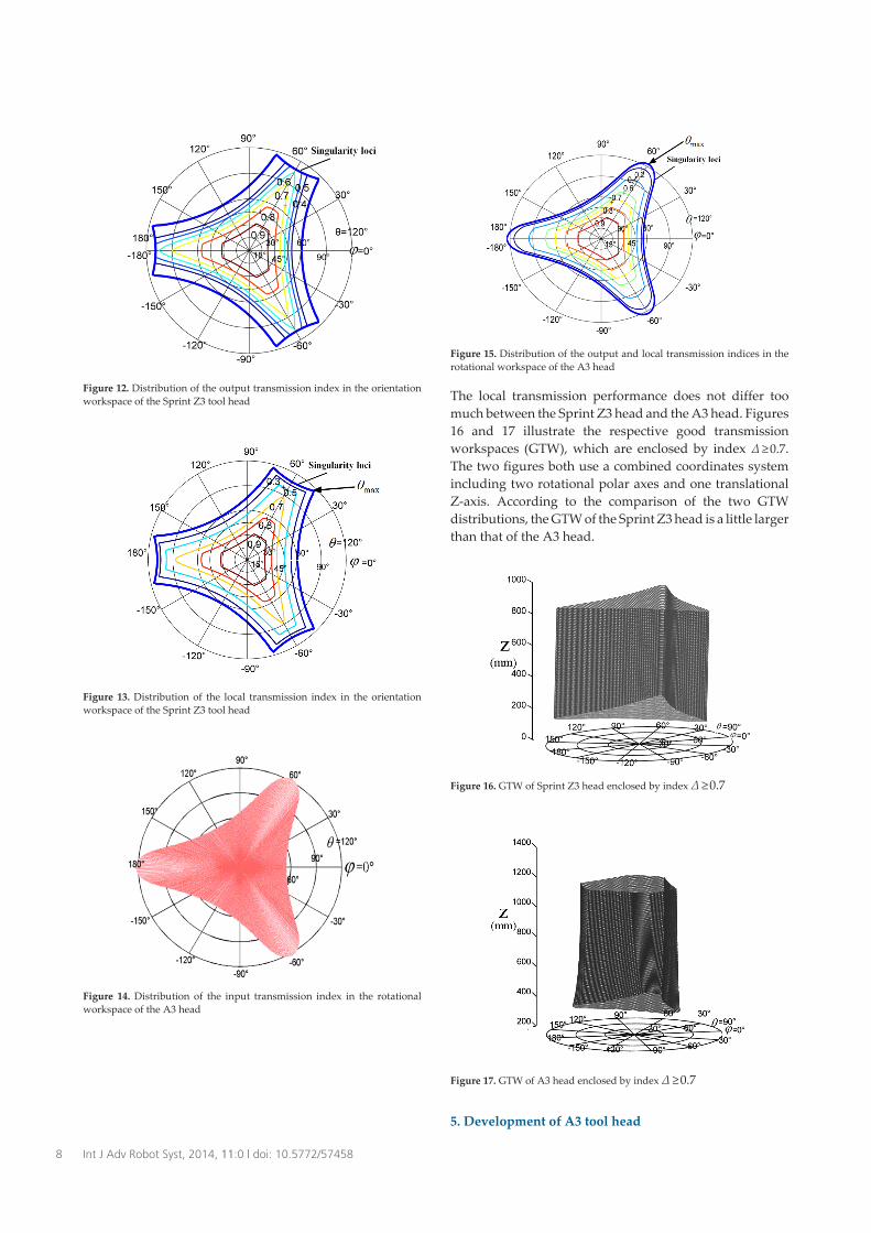
Figure 12. Distribution of the output transmission index in the orientationworkspace of the Sprint Z3 tool head
Figure 13. Distribution of the local transmission index in the orientationworkspace of the Sprint Z3 tool head
Figure 14. Distribution of the input transmission index in the rotationalworkspace of the A3 head
Figure 15. Distribution of the output and local transmission indices in therotational workspace of the A3 head
The local transmission performance does not differ toomuch between the Sprint Z3 head and the A3 head. Figures16 and 17 illustrate the respective good transmissionworkspaces (GTW), which are enclosed by index Δ ≥0.7.The two figures both use a combined coordinates systemincluding two rotational polar axes and one translationalZ-axis. According to the comparison of the two GTWdistributions, the GTW of the Sprint Z3 head is a little largerthan that of the A3 head.
Figure 16. GTW of Sprint Z3 head enclosed by index Δ ≥0.7
Figure 17. GTW of A3 head enclosed by index Δ ≥0.7
5. Development of A3 tool head
8 Int J Adv Robot Syst, 2014, 11:0 | doi: 10.5772/57458

An A3 tool head mechanism has been manufactured byTianjin University in China (Figure 18), which will furthercontribute to experiments on motion/force transmissionperformance.
Figure 18. Prototype of A3 tool head
6. Conclusions
The Sprint Z3 head and the A3 head share commonproperties, such as similar actuation in the prismatic pairs,1T2R DOFs with zero-torsion capability, and the sameparasitic motions. On the other hand, from the comparisonstudy of the two important tool heads in industry in termsof motion/force transmission performance, some distinc‐tions can be drawn:
1. In the case of unequal base and mobile platform radii,the motion/force transmission capability of the A3head gets better as the telescopic limbs extend. In thecase of equal radii, the A3 head mimics the Sprint Z3head’s homogenous transmission capability along theZ-axis. In contrast, due to its structural properties theSprint Z3 head can always possess homogeneousmotion/force transmission performance, regardless ofthe parameters.
2. The motion/force transmission power coefficient in theinput members of the Sprint Z3 head is always lessthan that of the A3 head, which has an input transmis‐sion index of unity. The power from the input mem‐bers of the A3 head can always be fully transmitted.
3. At the same fixed translational position, the maximumreachable tilt angle, θmax, of the A3 head is slightlygreater than that of the Sprint Z3 head, indicating thatthe A3 head has a larger rotational workspace than theSprint Z3 head with the same structural parameters.However, the GTW (the workspace enclosed byΔ ≥0.7) of the Sprint Z3 head is slightly greater than thatof the A3 head.
In sum, the comparison study results indicate that the A3head with optimal parameters outperforms the Sprint Z3head to some extent in terms of motion/force transmissi‐
bility, providing a desirable alternative for industrialapplication.
7. Acknowledgements
This project is supported by the National Natural ScienceFoundation of China (grant no. 51135008) and the NationalBasic Research Programme (973 Programme) of Chinaunder grant no. 2013CB035400.
8. References
[1] Stewart D (1965) A platform with six degrees offreedom. Proc. Inst. Mech. Eng. 180(5): 371-386.
[2] Umar A (2012) Design of a parallel robot with a largeworkspace for the functional evaluation of aircraftdynamics beyond the nominal flight envelope. Int.J. Adv. Robotic Sy. 9: 1-13.
[3] Dasgupta B, Mruthyunjaya T S (2000) The Stewartplatform manipulator: a review. Mech. Mach.Theory 35: 15-40.
[4] Xie F G, Liu X-J, Wang J S (2011) Performanceevaluation of redundant parallel manipulatorsassimilating motion/force transmissibility. Int. J.Adv. Robotic Sy. 8 (5): 113-124.
[5] Clavel R (1988) Delta: a fast robot with parallelgeometry, Proc. 18th Int. Symp. Ind. Robots, Sydney,Australia: 91-100.
[6] Siciliano B (1999) The Tricept robot: Inverse kine‐matics, manipulability analysis and closed-loopdirect kinematics algorithm. Robotica 17: 437-445.
[7] Bi Z M, Jin Y (2011) Kinematic modeling of Exechonparallel kinematic machine. Robot. Com-Int.Manuf. 27: 186-193.
[8] Wahl J (2000) Articulated Tool Head. Germany,WIPO Patent, No. WO/20 00/25976.
[9] Pond G, Carretero J A (2009) Architecture optimi‐zation of three 3-PRS variants for parallel kinematicmachining. Robot. Com-Int. Manuf. 25: 64-72.
[10] Carretero J A, Podhorodeski R P, Nahon M A,Gosselin C M (2000) Kinematic analysis andoptimization of a new three degree-of-freedomspatial parallel manipulator. J. Mech. D. 122(1):17-24.
[11] Huang T, Liu H T (2007) A parallel device havingdouble rotation freedoms and one translationfreedom. PCT Patent No. WO 2007/ 124637.
[12] Liu X-J, Bonev I A (2008) Orientation capability,error analysis, and dimensional optimization of twoarticulated tool heads with parallel kinematics. J.Manuf. Sci. Engn. 130: 011015-1-9.
9Xiang Chen, Xin-Jun Liu, FuGui Xie and Tao Sun:A Comparison Study on Motion/Force Transmissibility of...

[13] Tsai M S, Shiau T N, Tsai Y J, Chang T H (2003)Direct kinematic analysis of a 3-PRS parallelmechanism. Mech. Mach. Theory 38: 71-83.
[14] Peng B B, Li Z M, Wu K, Sun T (2011) Kinematiccharacteristics of 3-UPU parallel manipulator insingularity and its application. Int. J. Adv. RoboticSy. 8(4): 54-64.
[15] Li Y M, Xu Q S (2005) Kinematics and inversedynamics analysis for a general 3-PRS spatialparallel mechanism. Robotica 23: 219-229.
[16] Alexei S, Paul X (2006) Dynamics analysis of a 3-DOF parallel manipulator with R-P-S joints struc‐ture. Mech. Mach. Theory 42: 541-557.
[17] Wang J S, Wu C, Liu X-J (2010) Performanceevaluation of parallel manipulators: Motion/forcetransmissibility and its index. Mech. Mach. Theory45(10): 1462-1476.
[18] Li Q C, Chen Z, Chen Q H, et al. (2011) Parasiticmotion comparison of 3-PRS parallel mechanismwith different limb arrangements. Robot. Com-Int.Manuf. 27: 389-396.
[19] Rico J M, Duffy J (2000) Forward and inverseacceleration analyses of in-parallel manipulators. J.Mech. Des. 122(3): 299-303.
[20] Ball R S (1900) A treatise on the theory of screws.Cambridge University Press, Cambridge, UK.
[21] Liu X-J, Wang J S, Kim J (2006) Determination of thelink lengths for a spatial 3-DoF parallel manipula‐tor. J. Mech. D. 128: 365-373.
[22] Li Y G, Liu H T, Zhao X M, Huang T, Chetwynd DG (2010) Design of a 3-DOF PKM module for largestructural component machining. Mech. Mach.Theory 45: 941-954.
10 Int J Adv Robot Syst, 2014, 11:0 | doi: 10.5772/57458

![Model Updating Based on MDOF Transmissibility … Updating Based on MDOF Transmissibility Concept ... An example with interest ... cial code developed by ANSYS APDL [7]](https://img.pdfslide.us/doc/110x75/5b1c877c7f8b9a2d258fe46b/model-updating-based-on-mdof-transmissibility-updating-based-on-mdof-transmissibility.jpg)