Embed Size (px)
Citation preview
CLAWAR 2020: 23rd International Conference on Climbing and Walking Robots and the Support Technologies for Mobile Machines, Moscow, Russian Federation, 24-26 August 2020. https://doi.org/10.13180/clawar.2020.24-26.08.43
© CLAWAR Association Ltd 212
A COMPACT LASER SHEAROGRAPHY SYSTEM INTEGRATED WITH ROBOTIC CLIMBER FOR ON-SITE INSPECTION OF WIND TURBINE
BLADES
ZHIYAO LI, M. OSMAN TOKHI, ZHANFANG ZHAO
Division of the Electrical and Electronic Engineering, London South Bank University, London, United Kingdom
JIANXIN GAO*, HAITAO ZHENG TWI LTD, Cambridge, UK
* Corresponding author E-mail: [email protected]
Shearography is an optical technique in the field of non-destructive evaluation (NDE) of various materials, with the main advantages of non-contact and relatively large area of coverage in a single inspection. It has been widely acknowledged as an effective technique particularly for NDE of composite materials to detect subsurface defects such as delamination, disbond, cracks and impact damages. However, the use of shearography to inspect wind turbine blades (WTB) on site a wind tower is not proven, because a WTB is in constant vibration due to wind even when it is parked on a tower at low-speed wind. To address the problem, we aim to attach the shearography sit onto the WTB during inspection when the WTB is parked, the relatively motion between the shearography and the WTB is minimized within the tolerance of the shearography system. The ultimate goal is to develop a robot assisted shearography system able to inspect the WTBs on-site through remote control by operators on the ground (for onshore wind turbines) or on a vessel (for off-shore wind turbines), so that there is no need to send humans to the wind tower via a rope to do the inspections. This paper reports part of our research work surrounding the new shearography that is designed for integration with a robotic climber for on-site WTB inspection. It includes the principle of shearography, comparison of shearography with other NDE technologies, robotic application, experiments validation for fringe patterns, and description of post processing algorithms.
1. Introduction
Structural integrity is important for the safe operations of the engineering structures and industrial facilities. In a wind turbine, the wind turbine blades (WTBs) are a critical component whose structural failure may result in catastrophic consequence even hundred meters away from the site if part of a WTB is thrown away. As wind turbines are expected to generate electricity 90% of the time during a typical lifetime of 20 years, structural flaws in WTBs are of great concern [1]. Therefore, WTBs require regular inspection and maintenance in order to ensure defects caused or developed during operation can be found at the early stage. Otherwise, the small defects beneath the surface may develop into big ones, possibly leading to a catastrophic accident. Thus, engineers and scientists are looking for various methods to conduct NDE of WTBs after installation on a wind tower.
Numerous NDE techniques have been widely used in industry, but few can be applied to the inspection of in-situ WTBs. Ultrasonic testing is a point-wise contact inspection technique and is usually only suitable for homogeneous materials, hence is difficult to apply to on-site inspection of WTBs. Radiography especially computer tomography is a powerful technique widely used in industry. However, its deployment to the wind tower is difficult. Thermography is a promising NDE technique, but its application to on-site WTB inspection has yet to be
213
proven, given the environmental temperature change due to wind flow which will add considerable noise to the captured thermal images.
Shearography as an optical technique has the main advantages of non-contact and relatively large area of coverage in a single inspection. It was first proposed by Leendertz and Butters in 1973 [2] and was further developed by Hung since the 1980s [3,4,5]. Thus, shearography has been recognised as a powerful inspection technique, and has found wide application in a range of industries including the aerospace, automotive and shipbuilding sectors. Guelker [ 6 ] used shearography to inspect buildings and monuments, which showed a better result in comparison to other NDT methods. Hung [7] has pointed that shearography is more suitable for inspecting composite material because of its capability of measuring the derivatives of the. Niezrecki et al [8] have given a systematic comparison for five NDE methods based on a CX-100 blade sample for their performance. In their tests, shearography has shown better results in terms of full-field identification of flaws and subsurface defects. Likewise, a detailed comparison between different NDE techniques for WTB inspection has been summarized by Yang et al [9]. Hung et al [ 10 ] have developed fringe analysis and phase shift techniques for interpretation of shearography results, where typical butterfly fringe patterns indicate stress concentration caused by subsurface defects. By adopting phase shift technique [11], quantitative phase maps could be retrieved for further evaluation. Phase shift could be temporal and spatial based on different phase shift mechanisms. Temporal phase shift [12,13] is widely used for phase mapping which can yield relatively clearer results than those of spatial phase shift. However, temporal phase shift is usually only suitable for static or semi-dynamic conditions, and not in dynamic conditions such as on a wind tower [ 14 ]. Spatial phase shift requires more computational processing and the hardware is much complicated. Nevertheless, it is tempting to develop spatial phase shift as the real-time measurement technique in the demanding industrial conditions [15].
It should be noted that all existing shearography techniques are operated on the ground, and their application for on-site inspection of a WTB has not been demonstrated. Since the WTB is subject to constant vibration due to wind even when it is parked on a tower at low-speed wind, it is believed that the only solution for shearography to work on a wind tower is to attach it on the WTB surface during inspection while the WTB is parked so that the relatively motion between the shearography and the WTB is within the tolerance of the shearography system. The integration of NDE equipment with a robotic carrier or climber is the trend in industry. In fact, for application to WTBs, there are various choices of on-the-shelf robotic systems which can carry simple monitoring equipment such as visual inspection [16,17,18]. However, there are no reports showing a practical robot-assisted shearography for on-site WTB inspection. Our ultimate goal is to develop a robot-assisted shearography system, which is able to inspect the WTBs on-site through remote control without having to send humans to the wind tower via a rope to do the inspections. This paper reports part of the research work surrounding the new shearography that is designed for integration with a robotic climber for on-site WTB inspection. The principle and processing algorithms are also explained. A specific robotic climber which has a high payload and was developed by ICM (International Climbing Machines, USA) has been selected for integration. The climber has been further adapted by our project partners. The paper shows test evaluations of the shearography system, and feasibility study of post processing of phase shift analysis for future development.
2. Shearography design principle
Shearography or so called DSSPI (digital shearing speckle pattern interferometry) and its related systems such as ESPI [19] are based on different optical interferometers which split a single laser
214
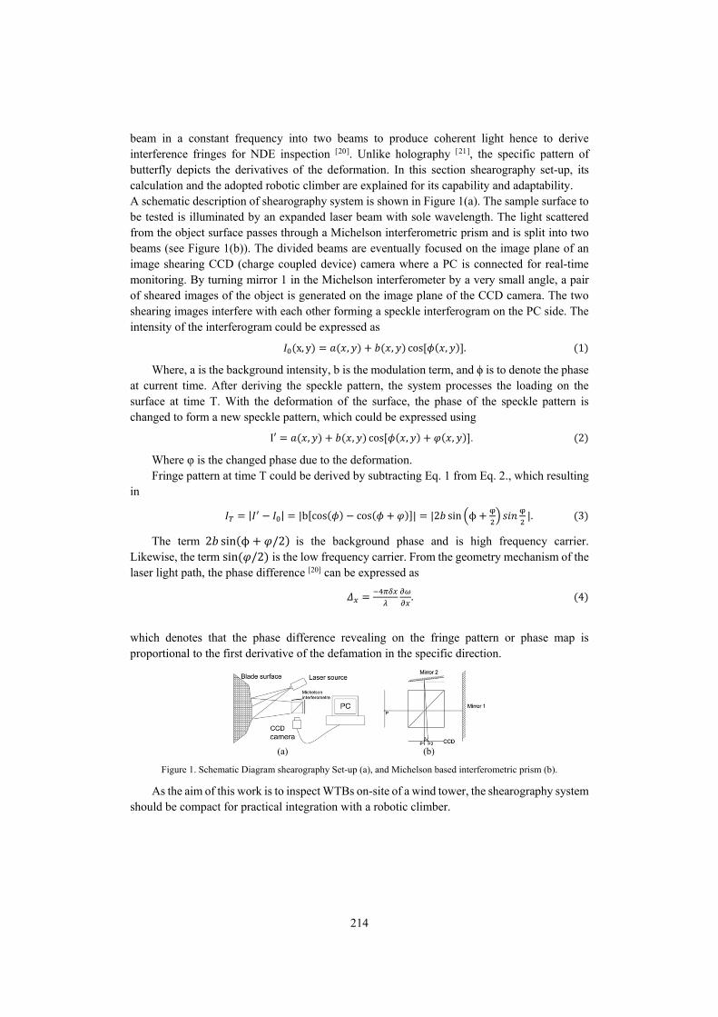
beam in a constant frequency into two beams to produce coherent light hence to derive interference fringes for NDE inspection [20]. Unlike holography [21], the specific pattern of butterfly depicts the derivatives of the deformation. In this section shearography set-up, its calculation and the adopted robotic climber are explained for its capability and adaptability. A schematic description of shearography system is shown in Figure 1(a). The sample surface to be tested is illuminated by an expanded laser beam with sole wavelength. The light scattered from the object surface passes through a Michelson interferometric prism and is split into two beams (see Figure 1(b)). The divided beams are eventually focused on the image plane of an image shearing CCD (charge coupled device) camera where a PC is connected for real-time monitoring. By turning mirror 1 in the Michelson interferometer by a very small angle, a pair of sheared images of the object is generated on the image plane of the CCD camera. The two shearing images interfere with each other forming a speckle interferogram on the PC side. The intensity of the interferogram could be expressed as
x, y , , cos , . 1
Where, a is the background intensity, b is the modulation term, and ϕ is to denote the phase at current time. After deriving the speckle pattern, the system processes the loading on the surface at time T. With the deformation of the surface, the phase of the speckle pattern is changed to form a new speckle pattern, which could be expressed using
I′ , , cos , , . 2
Where φ is the changed phase due to the deformation. Fringe pattern at time T could be derived by subtracting Eq. 1 from Eq. 2., which resulting
in
| | |b cos cos | |2 sin ϕ |. 3
The term 2 sin ϕ /2 is the background phase and is high frequency carrier. Likewise, the term sin /2 is the low frequency carrier. From the geometry mechanism of the laser light path, the phase difference [20] can be expressed as
. 4
which denotes that the phase difference revealing on the fringe pattern or phase map is proportional to the first derivative of the defamation in the specific direction.
(a) (b)
Figure 1. Schematic Diagram shearography Set-up (a), and Michelson based interferometric prism (b).
As the aim of this work is to inspect WTBs on-site of a wind tower, the shearography system should be compact for practical integration with a robotic climber.
215
3. Methodology
3.1. Shearography design and realization
Existing shearography systems on the market have implemented phase shift techniques for result quantification. The widely mentioned phase shift techniques are temporal phase shift [12,13] which will need static condition to process. Although dynamic phase shift [14] is currently being researched, it still requires several seconds to initiate the reference within fully static condition, which is not practical for shearography’s utilization on the WTB, because in the initialization process, the ambient condition is unpredictable and mostly is fully dynamic. For this reason, temporal real-time phase shift is hard to accomplished with automatic maneuvering on the sky. Spatial phase shift techniques on the other hand, require relatively complicated hardware configuration as well as expensive computational calculations. For example, if a four-camera spatial phase shift is applied on the WTB with automation, the overall weight of the shearography system will be well beyond the payload of the robotic climber.
To date, the most practical real-time NDE based on shearography technique is the subtraction of speckle pattern before and after loading. The step of the shearography process is shown in the flow chart of Figure 2.
Figure 2. Shearography working flow chart.
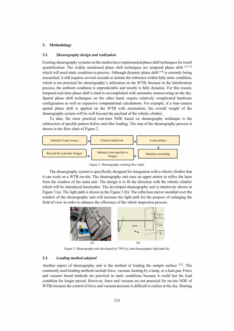
The shearography system is specifically designed for integration with a robotic climber that it can work on a WTB on-site. The shearography unit uses an upper mirror to reflex the laser from the window of the main unit. The design is to fit the direction with the robotic climber which will be introduced hereinafter. The developed shearography unit is intuitively shown in Figure 3 (a). The light path is shown in the Figure 3 (b). The reflection mirror installed over the window of the shearography unit will increase the light path for the purpose of enlarging the field of view in order to enhance the efficiency of the whole inspection process.
(a) (b)
Figure 3. Shearography unit developed by TWI (a), and shearography light path (b).
3.2. Loading method adopted
Another aspect of shearography unit is the method of loading the sample surface [22]. The commonly used loading methods include force, vacuum, heating by a lamp, or a heat gun. Force and vacuum based methods are practical in static conditions because it could last the load condition for longer period. However, force and vacuum are not practical for on-site NDE of WTBs because the control of force and vacuum pressure is difficult to realize in the sky. Heating
Initialize Laser source Camera turned on Load surface
Initialize recording Subtract from speckle to fringes
Record the real-time fringes
216
lamp was considered to have less control complexity by comparison with the above two methods, however, the heat exerted on the WTB surface is insufficient to deform the WTB for shearography inspection Moreover, the weight and size of a lamp is much higher than a heat air flow equipment. Therefore, heat gun was used for the loading process in this work.
3.3. Robotic climber
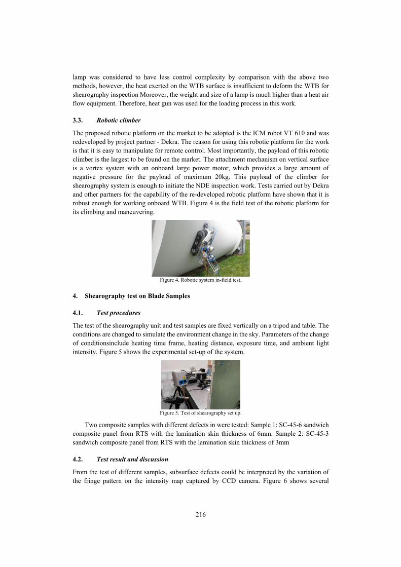
The proposed robotic platform on the market to be adopted is the ICM robot VT 610 and was redeveloped by project partner - Dekra. The reason for using this robotic platform for the work is that it is easy to manipulate for remote control. Most importantly, the payload of this robotic climber is the largest to be found on the market. The attachment mechanism on vertical surface is a vortex system with an onboard large power motor, which provides a large amount of negative pressure for the payload of maximum 20kg. This payload of the climber for shearography system is enough to initiate the NDE inspection work. Tests carried out by Dekra and other partners for the capability of the re-developed robotic platform have shown that it is robust enough for working onboard WTB. Figure 4 is the field test of the robotic platform for its climbing and maneuvering.
Figure 4. Robotic system in-field test.
4. Shearography test on Blade Samples
4.1. Test procedures
The test of the shearography unit and test samples are fixed vertically on a tripod and table. The conditions are changed to simulate the environment change in the sky. Parameters of the change of conditionsinclude heating time frame, heating distance, exposure time, and ambient light intensity. Figure 5 shows the experimental set-up of the system.
Figure 5. Test of shearography set up.
Two composite samples with different defects in were tested: Sample 1: SC-45-6 sandwich composite panel from RTS with the lamination skin thickness of 6mm. Sample 2: SC-45-3 sandwich composite panel from RTS with the lamination skin thickness of 3mm
4.2. Test result and discussion
From the test of different samples, subsurface defects could be interpreted by the variation of the fringe pattern on the intensity map captured by CCD camera. Figure 6 shows several
217
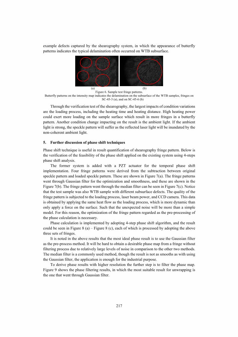
example defects captured by the shearography system, in which the appearance of butterfly patterns indicates the typical delamination often occurred on WTB subsurface.
(a) (b)
Figure 6. Sample test fringe patterns. Butterfly patterns on the intensity map indicates the delamination on the subsurface of the WTB samples, fringes on
SC-45-3 (a), and on SC-45-6 (b)
Through the verification test of the shearography, the largest impacts of condition variations are the loading process, including the heating time and heating distance. High heating power could exert more loading on the sample surface which result in more fringes in a butterfly pattern. Another condition change impacting on the result is the ambient light. If the ambient light is strong, the speckle pattern will suffer as the reflected laser light will be inundated by the non-coherent ambient light.
5. Further discussion of phase shift techniques
Phase shift technique is useful in result quantification of shearography fringe pattern. Below is the verification of the feasibility of the phase shift applied on the existing system using 4-steps phase shift analysis.
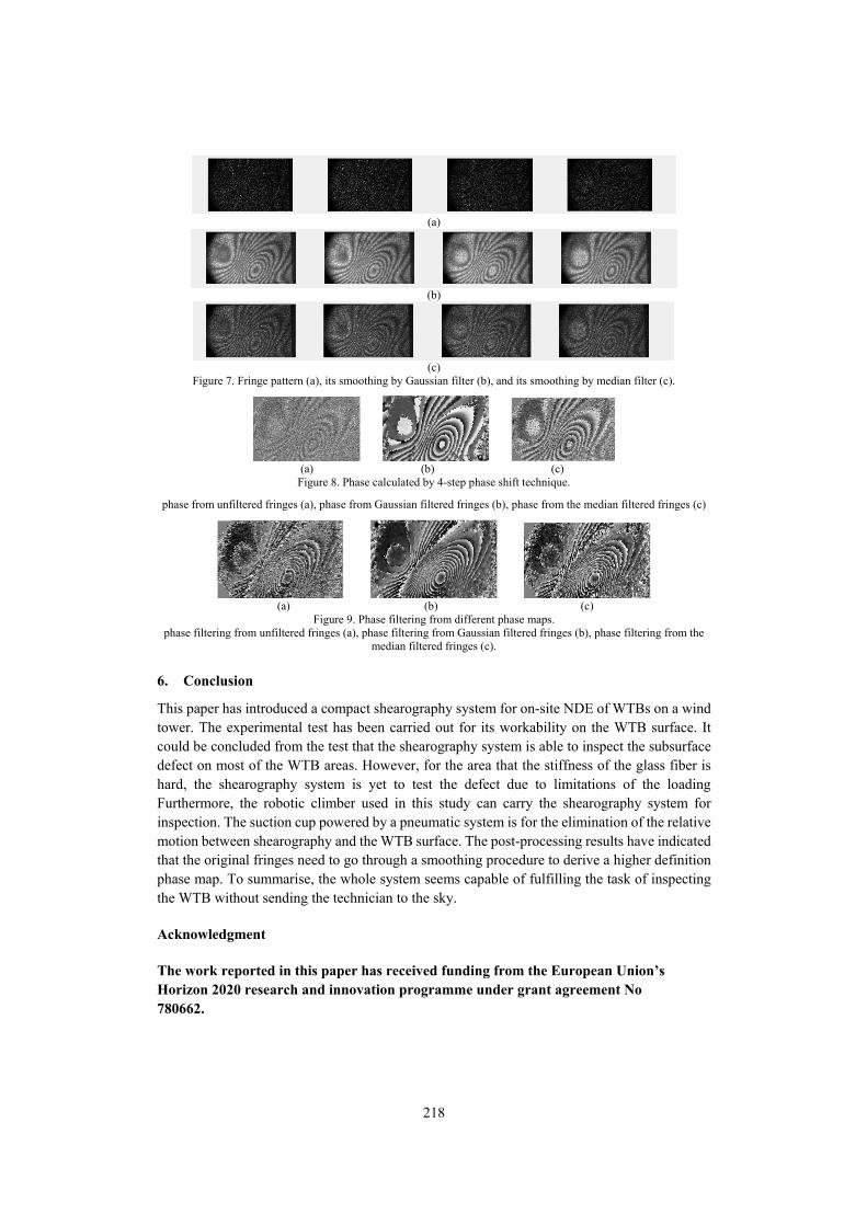
The former system is added with a PZT actuator for the temporal phase shift implementation. Four fringe patterns were derived from the subtraction between original speckle pattern and loaded speckle pattern. These are shown in Figure 7(a). The fringe patterns went through Gaussian filter for the optimization and smoothness, and these are shown in the Figure 7(b). The fringe pattern went through the median filter can be seen in Figure 7(c). Notice that the test sample was also WTB sample with different subsurface defects. The quality of the fringe pattern is subjected to the loading process, laser beam power, and CCD camera. This data is obtained by applying the same heat flow as the loading process, which is more dynamic than only apply a force on the surface. Such that the unexpected noise will be more than a simple model. For this reason, the optimization of the fringe pattern regarded as the pre-processing of the phase calculation is necessary.
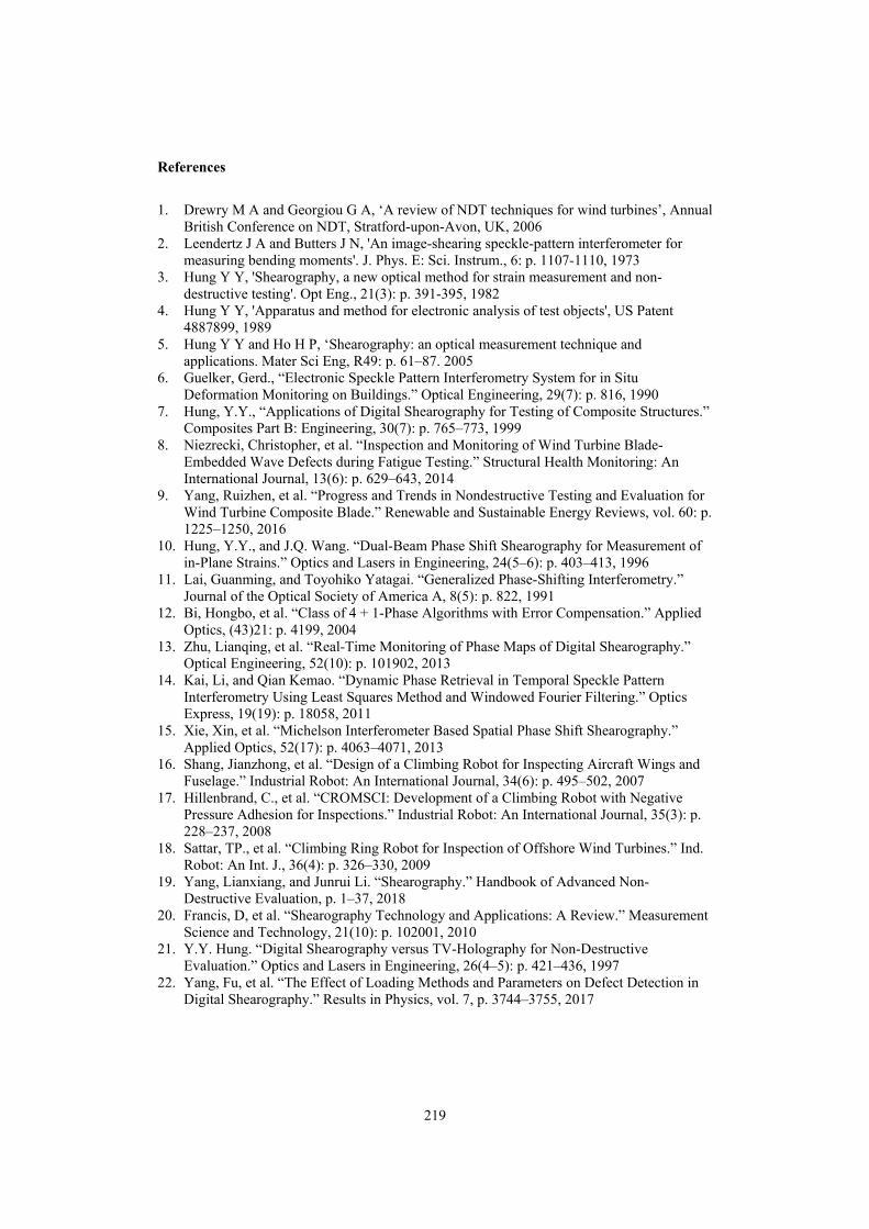
Phase calculation is implemented by adopting 4-step phase shift algorithm, and the result could be seen in Figure 8 (a) – Figure 8 (c), each of which is processed by adopting the above three sets of fringes.
It is noted in the above results that the most ideal phase result is to use the Gaussian filter as the pre-process method. It will be hard to obtain a desirable phase map from a fringe without filtering process due to relatively large levels of noise in comparison to the other two methods. The median filter is a commonly used method, though the result is not as smooths as with using the Gaussian filter, the application is enough for the industrial purpose.
To derive phase results with higher resolution the further step is to filter the phase map. Figure 9 shows the phase filtering results, in which the most suitable result for unwrapping is the one that went through Gaussian filter.
218
(a)
(b)
(c)
Figure 7. Fringe pattern (a), its smoothing by Gaussian filter (b), and its smoothing by median filter (c).
(a) (b) (c)
Figure 8. Phase calculated by 4-step phase shift technique.
phase from unfiltered fringes (a), phase from Gaussian filtered fringes (b), phase from the median filtered fringes (c)
(a) (b) (c)
Figure 9. Phase filtering from different phase maps. phase filtering from unfiltered fringes (a), phase filtering from Gaussian filtered fringes (b), phase filtering from the
median filtered fringes (c).
6. Conclusion
This paper has introduced a compact shearography system for on-site NDE of WTBs on a wind tower. The experimental test has been carried out for its workability on the WTB surface. It could be concluded from the test that the shearography system is able to inspect the subsurface defect on most of the WTB areas. However, for the area that the stiffness of the glass fiber is hard, the shearography system is yet to test the defect due to limitations of the loading Furthermore, the robotic climber used in this study can carry the shearography system for inspection. The suction cup powered by a pneumatic system is for the elimination of the relative motion between shearography and the WTB surface. The post-processing results have indicated that the original fringes need to go through a smoothing procedure to derive a higher definition phase map. To summarise, the whole system seems capable of fulfilling the task of inspecting the WTB without sending the technician to the sky.
Acknowledgment
The work reported in this paper has received funding from the European Union’s Horizon 2020 research and innovation programme under grant agreement No 780662.
219
References
1. Drewry M A and Georgiou G A, ‘A review of NDT techniques for wind turbines’, Annual British Conference on NDT, Stratford-upon-Avon, UK, 2006
2. Leendertz J A and Butters J N, 'An image-shearing speckle-pattern interferometer for measuring bending moments'. J. Phys. E: Sci. Instrum., 6: p. 1107-1110, 1973
3. Hung Y Y, 'Shearography, a new optical method for strain measurement and non-destructive testing'. Opt Eng., 21(3): p. 391-395, 1982
4. Hung Y Y, 'Apparatus and method for electronic analysis of test objects', US Patent 4887899, 1989
5. Hung Y Y and Ho H P, ‘Shearography: an optical measurement technique and applications. Mater Sci Eng, R49: p. 61–87. 2005
6. Guelker, Gerd., “Electronic Speckle Pattern Interferometry System for in Situ Deformation Monitoring on Buildings.” Optical Engineering, 29(7): p. 816, 1990
7. Hung, Y.Y., “Applications of Digital Shearography for Testing of Composite Structures.” Composites Part B: Engineering, 30(7): p. 765–773, 1999
8. Niezrecki, Christopher, et al. “Inspection and Monitoring of Wind Turbine Blade-Embedded Wave Defects during Fatigue Testing.” Structural Health Monitoring: An International Journal, 13(6): p. 629–643, 2014
9. Yang, Ruizhen, et al. “Progress and Trends in Nondestructive Testing and Evaluation for Wind Turbine Composite Blade.” Renewable and Sustainable Energy Reviews, vol. 60: p. 1225–1250, 2016
10. Hung, Y.Y., and J.Q. Wang. “Dual-Beam Phase Shift Shearography for Measurement of in-Plane Strains.” Optics and Lasers in Engineering, 24(5–6): p. 403–413, 1996
11. Lai, Guanming, and Toyohiko Yatagai. “Generalized Phase-Shifting Interferometry.” Journal of the Optical Society of America A, 8(5): p. 822, 1991
12. Bi, Hongbo, et al. “Class of 4 + 1-Phase Algorithms with Error Compensation.” Applied Optics, (43)21: p. 4199, 2004
13. Zhu, Lianqing, et al. “Real-Time Monitoring of Phase Maps of Digital Shearography.” Optical Engineering, 52(10): p. 101902, 2013
14. Kai, Li, and Qian Kemao. “Dynamic Phase Retrieval in Temporal Speckle Pattern Interferometry Using Least Squares Method and Windowed Fourier Filtering.” Optics Express, 19(19): p. 18058, 2011
15. Xie, Xin, et al. “Michelson Interferometer Based Spatial Phase Shift Shearography.” Applied Optics, 52(17): p. 4063–4071, 2013
16. Shang, Jianzhong, et al. “Design of a Climbing Robot for Inspecting Aircraft Wings and Fuselage.” Industrial Robot: An International Journal, 34(6): p. 495–502, 2007
17. Hillenbrand, C., et al. “CROMSCI: Development of a Climbing Robot with Negative Pressure Adhesion for Inspections.” Industrial Robot: An International Journal, 35(3): p. 228–237, 2008
18. Sattar, TP., et al. “Climbing Ring Robot for Inspection of Offshore Wind Turbines.” Ind. Robot: An Int. J., 36(4): p. 326–330, 2009
19. Yang, Lianxiang, and Junrui Li. “Shearography.” Handbook of Advanced Non-Destructive Evaluation, p. 1–37, 2018
20. Francis, D, et al. “Shearography Technology and Applications: A Review.” Measurement Science and Technology, 21(10): p. 102001, 2010
21. Y.Y. Hung. “Digital Shearography versus TV-Holography for Non-Destructive Evaluation.” Optics and Lasers in Engineering, 26(4–5): p. 421–436, 1997
22. Yang, Fu, et al. “The Effect of Loading Methods and Parameters on Defect Detection in Digital Shearography.” Results in Physics, vol. 7, p. 3744–3755, 2017


![Ultra-compact Laser Sensor [Amplifier Built-in] EX … and Brochures/ex-l200.pdfUltra-compact Laser Sensor Amplifier Built-in EX-L200 SERIES ... PNP output type available ... SPOT](https://img.pdfslide.us/doc/110x75/5aa8194e7f8b9aa2258b6a89/ultra-compact-laser-sensor-amplifier-built-in-ex-and-brochuresex-l200pdfultra-compact.jpg)