Embed Size (px)
Citation preview
JOHNS HOPKINS APL TECHNICAL DIGEST, VOLUME 30, NUMBER 4 (2012) 331
INTRODUCTIONFuture unmanned NASA missions to small planetary
bodies, such as asteroids, moons, and even comets, are anticipated in which extremely close station-keeping and soft landings would be accomplished with high accuracy, tight repeatability, and minimal risk. Accurate range, descent rate, attitude, and translational velocities must be measured to enable precision landing or prox-imity loitering at very low drift velocities (e.g., 1 cm/s)
in low-gravity environments. Operational ranges for the landing phase are expected to be at most a few kilome-ters down to less than 1 m.
Because of significant round-trip data link times, the proposed terminal guidance mode for landing must be executed by the subject spacecraft autonomously, inde-pendent of ground control. Poorly characterized landing sites may require real-time obstacle avoidance and can
PL has developed a compact laser altimeter capability to enable small spacecraft missions to rendezvous with low-gravity planetary bodies, such as asteroids,
comets, and moons. Precision range data have been shown to signif icantly improve spacecraft control in close-approach and landing scenarios, and not surprisingly, the data are most critical in the final descent phase where the spacecraft is within a few kilometers to a few meters from the target surface. These missions require both improved precision from previously flown lidar technologies as well as much reduced size, weight, and power given the resource-constrained class of missions likely to use this capability. APL has been pursuing a prototype laser altimeter that achieves the desired ranging accuracy and precision while requiring minimal resources from the spacecraft bus.
A Compact Laser Altimeter for Spacecraft Landing Applications
Jonathan R. Bruzzi, Kim Strohbehn, Bradley G. Boone, Samuel Kerem, Russell S. Layman, and Matthew W. Noble
J. R. BRUZZI ET AL.
JOHNS HOPKINS APL TECHNICAL DIGEST, VOLUME 30, NUMBER 4 (2012)332
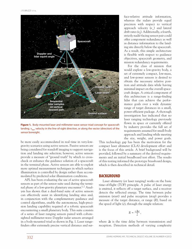
face-relative attitude information, whereas the radars provide equal precision with respect to vertical approach velocity (v) and lateral drift rates (v). Additionally, a fourth, strictly nadir-facing sensor pair could offer component redundancy as well as distance information to the land-ing site directly below the spacecraft. As a result, this simple architecture is flexible with respect to guidance objectives, spacecraft geometry, and mission redundancy requirements.
For the class of mission that would explore a low-gravity body, a set of extremely compact, low-mass, and low-power sensors is desired to obtain the necessary relative posi-tion and attitude data while having minimal impact on the overall space-craft design. A critical component of this architecture is a range-finding lidar that can achieve the perfor-mance goals over a wide dynamic range of target distances in a small, power-efficient package. A thorough investigation has indicated that no laser ranging technology previously flown in space or currently offered by industry provides the full set of requirements assumed for small-body approach and landing while meeting the size, weight, and power goals.
This technology gap has been the motivation for the compact laser altimeter (CLA) development effort and is the focus of this article. A brief background will be provided, followed by a summary of the derived require-ments and an initial breadboard test effort. The results of this testing informed the prototype brassboard design, which is then described in technical detail.
BACKGROUNDLaser altimetry (or laser ranging) works on the basic
time-of-flight (TOF) principle. A pulse of laser energy is emitted, it reflects off a target surface, and a receiver detects the reflected energy. The time between pulse emission (start) and pulse reception (stop) provides a measure of the target distance, or range (R), based on the speed of light (c), through the simple relation:
R c t2D= ,
where Dt is the time delay between transmission and reception. Detection methods of varying complexity
be more easily accommodated in real time in very-low-gravity scenarios using active sensors. Passive sensors are being considered for standoff imaging to support naviga-tion and landing site selection; however, active sensors provide a measure of “ground truth” by which to cross-check or enhance the guidance solution of a spacecraft in the terminal phase. Active sensors are able to exploit more optimal measurement techniques in which surface illumination is controlled by design rather than accom-modated by predicted solar illumination conditions.
APL has been evaluating the use of active spacecraft sensors as part of the sensor suite used during the termi-nal phase of a low-gravity planetary encounter.1, 2 Anal-ysis has shown that a dual-band suite of active sensors can effectively assist in identifying landing sites and, in conjunction with the complementary guidance and control algorithms, enable the autonomous, high-preci-sion landing capability required of a robotic spacecraft encountering a small planetary body. This suite consists of a series of laser ranging sensors paired with cobore-sighted millimeter-wave Doppler radar sensors arranged in a body-mounted triad as shown in Fig. 1. Laser range-finders offer extremely precise vertical distance and sur-
y x
z
vlos
120°
v||
v�
Spacecraft
Ground surface
Sequentiallidar samples
on verticaldescent path
Laser beam
Doppler beam
Doppler andlidar squint angle
Figure 1. Body-mounted laser and millimeter-wave sensor triad concept for spacecraft landing. vlos, velocity in the line-of-sight direction, or along the vector (direction) of the sensor boresight.
A COMPACT LASER ALTIMETER FOR SPACECRAFT LANDING
JOHNS HOPKINS APL TECHNICAL DIGEST, VOLUME 30, NUMBER 4 (2012) 333
DERIVED REQUIREMENTSAlthough space-based lidars and laser altimeters have
heritage back to the Apollo program, the requirements for heritage, nonlanding lidars are distinctly different from those for lidars that perform autonomous close approach and landing. Aside from those flown recently on the Japanese asteroid close-encounter mission, HAYABUSA (or MUSES-C),5 and the Air Force Research Laboratory’s experimental proximity operations spacecraft, XSS-11, the vast majority of space-based lidars have been used for long-standoff-range measurements and have therefore required both high laser energy and large receive apertures. A laser altimeter intended for a small-body encounter need not operate over very long distances; however, it must perform measurements over a large dynamic range of distances (i.e., from a few kilometers down to approximately 1 m). The measurements should also be highly accurate and have sufficient resolution, on the order of 1 cm, to enable precision control of the spacecraft in its approach to the surface. Real-time spacecraft guidance and control served by the altimeter would require more frequent measurement updates than typically provided by an instrument intended solely for
can be used to reveal char-acteristics of the target in addition to range, such as reflectance and roughness in the case of a hard target or, with additional analysis, chemical makeup in the case of an aerosol target, for example.
APL’s first venture into space-based laser altim-etry was with the Near Earth Asteroid Rendez-vous (NEAR) mission. The NEAR Laser Range-finder (NLR) was developed and flown by APL on the NEAR spacecraft launched in 1996.3 NLR successfully provided ranging mea-surements to the asteroid 433 Eros from a low-altitude orbit tens of kilometers to more than 100 kilometers above the asteroid’s surface. The altimetry data were used to map the topogra-phy of Eros and provide insight into its fundamental makeup. Although landing was not part of the original NLR or NEAR mission objectives, the mission con-cluded with a controlled landing on the asteroid’s sur-face; measurements from NLR were used to track the descent. Important lessons from the NLR development are being leveraged by the current CLA effort.
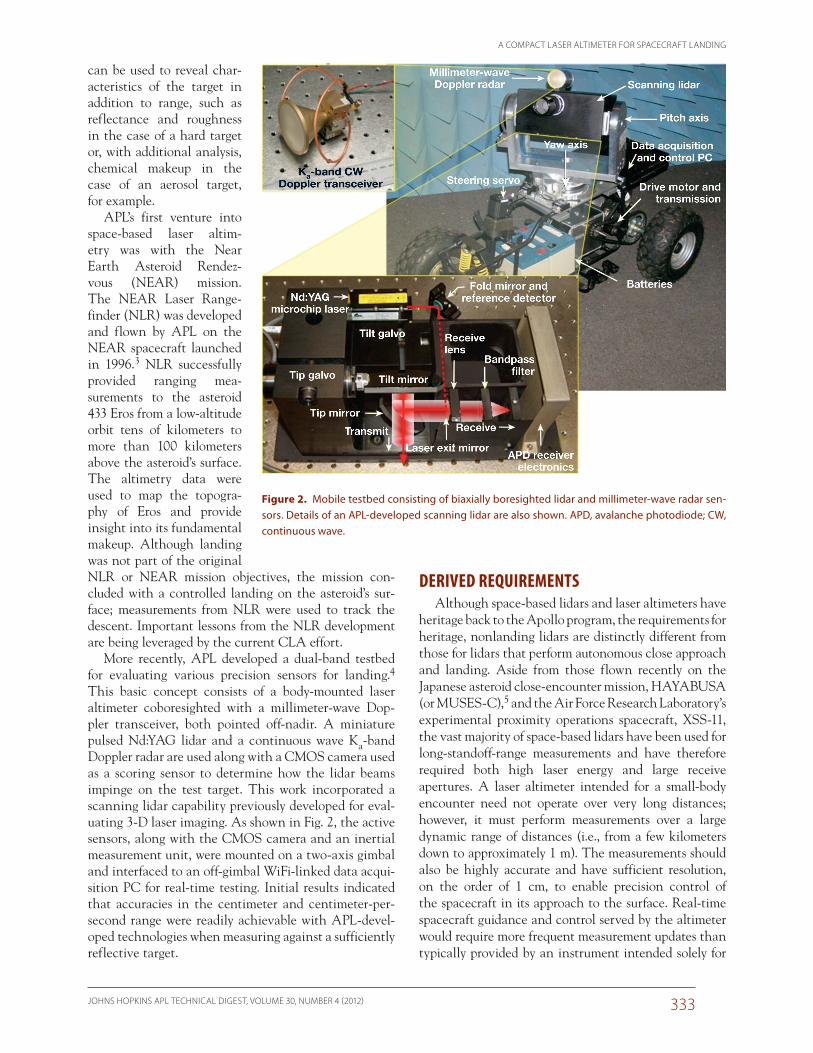
More recently, APL developed a dual-band testbed for evaluating various precision sensors for landing.4 This basic concept consists of a body-mounted laser altimeter coboresighted with a millimeter-wave Dop-pler transceiver, both pointed off-nadir. A miniature pulsed Nd:YAG lidar and a continuous wave Ka-band Doppler radar are used along with a CMOS camera used as a scoring sensor to determine how the lidar beams impinge on the test target. This work incorporated a scanning lidar capability previously developed for eval-uating 3-D laser imaging. As shown in Fig. 2, the active sensors, along with the CMOS camera and an inertial measurement unit, were mounted on a two-axis gimbal and interfaced to an off-gimbal WiFi-linked data acqui-sition PC for real-time testing. Initial results indicated that accuracies in the centimeter and centimeter-per-second range were readily achievable with APL-devel-oped technologies when measuring against a sufficiently reflective target.
Figure 2. Mobile testbed consisting of biaxially boresighted lidar and millimeter-wave radar sen-sors. Details of an APL-developed scanning lidar are also shown. APD, avalanche photodiode; CW, continuous wave.
J. R. BRUZZI ET AL.
JOHNS HOPKINS APL TECHNICAL DIGEST, VOLUME 30, NUMBER 4 (2012)334
resource allocation and sensor performance. How-ever, there are a number of design trades and consider-ations that were explored as part of a detailed analysis and breadboarding effort. For example, laser energy and direct current (DC) power consumption were traded against receive aper-ture and mass, and range measurement precision was traded against maximum distance capability.
Simple edge detection was selected for generat-
ing start and stop pulses in order to take advantage of APL-developed application-specific integrated circuits (ASICs) and to reduce the power and mass of the event-processing electronics.6 A consequence of using edge detection is that the stop-pulse timing must be done with a constant fraction discriminator (CFD) to make the pulse timing independent of pulse amplitude (an effect called “walk”). Therefore, effects of nonuniform target surface roughness and slope over the footprint of the transmit beam will also be included in the measure-ments, but they are not likely to be problematic because the beam spot will be quite small as the laser transmitter nears the target.
One design consideration paid particularly close attention was the transmit beam divergence. The laser beam may be biased to provide more overlap with the receiver field of view (FOV) at close range for short-distance operation or minimized to ensure the maxi-mum amount of reflected energy is captured within the FOV at long range. The breadboard effort concluded that not much overlap is required at close range after all because even a small amount of scatter from the target is detected given the relatively high laser pulse energy. However, close-range operation may require an addi-tional calibration step to account for the effects of close-in scatter, and attention may need to be paid to optimal ground spot size at critical ranges in order to ensure good backscatter from non-Lambertian or “worst-case” target surfaces.
Breadboard Design ApproachAnalysis was accompanied by a 2-year breadboard
design and performance characterization effort. To min-imize required spacecraft resources and ease transition to flight, a decision was made to keep the design archi-tecture simple and select components that have replace-ments with flight heritage. A compact lidar breadboard package was designed, built, and functionally tested in a
scientific study. Commercial lidars and laser rangefinders offer various advanced features and capabilities but may not be appropriate for operation in the space environment. These overarching themes, along with the highly constrained resource allocation expected for the class of mission pursuing small-body landing, have been the key drivers for developing the CLA. As previously stated, no single lidar technology previously flown in space or available from industry provides the full set of requirements assumed for small-body approach and landing, including the required precision, close-range capability, dynamic range, and update rate, while meeting the size, weight, and power goals.
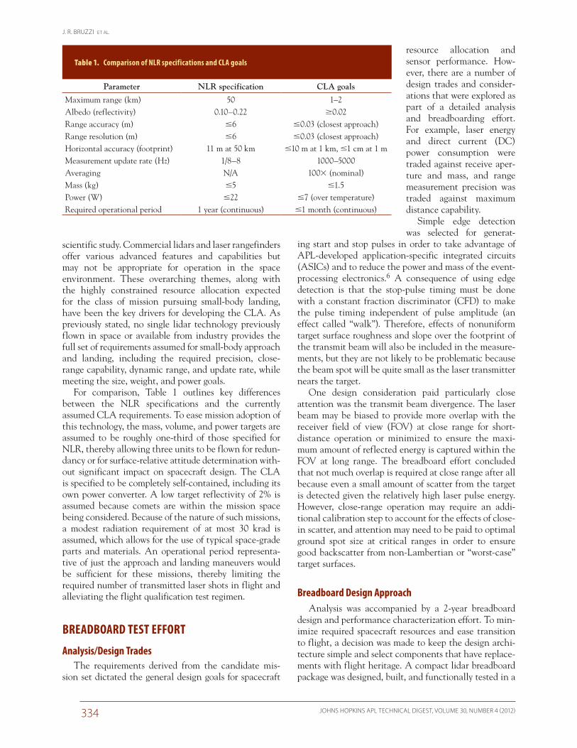
For comparison, Table 1 outlines key differences between the NLR specifications and the currently assumed CLA requirements. To ease mission adoption of this technology, the mass, volume, and power targets are assumed to be roughly one-third of those specified for NLR, thereby allowing three units to be flown for redun-dancy or for surface-relative attitude determination with-out significant impact on spacecraft design. The CLA is specified to be completely self-contained, including its own power converter. A low target reflectivity of 2% is assumed because comets are within the mission space being considered. Because of the nature of such missions, a modest radiation requirement of at most 30 krad is assumed, which allows for the use of typical space-grade parts and materials. An operational period representa-tive of just the approach and landing maneuvers would be sufficient for these missions, thereby limiting the required number of transmitted laser shots in flight and alleviating the flight qualification test regimen.
BREADBOARD TEST EFFORT
Analysis/Design TradesThe requirements derived from the candidate mis-
sion set dictated the general design goals for spacecraft
Table 1. Comparison of NLR specifications and CLA goals
Parameter NLR specification CLA goals
Maximum range (km) 50 1–2Albedo (reflectivity) 0.10–0.22 0.02Range accuracy (m) 6 0.03 (closest approach)Range resolution (m) 6 0.03 (closest approach)Horizontal accuracy (footprint) 11 m at 50 km 10 m at 1 km, 1 cm at 1 mMeasurement update rate (Hz) 1/8–8 1000–5000Averaging N/A 100 (nominal)Mass (kg) 5 1.5Power (W) 22 7 (over temperature)Required operational period 1 year (continuous) 1 month (continuous)
A COMPACT LASER ALTIMETER FOR SPACECRAFT LANDING
JOHNS HOPKINS APL TECHNICAL DIGEST, VOLUME 30, NUMBER 4 (2012) 335
ments by as much as 10 cm, as could variations in SNR, amplitude of the detector output, or the CFD threshold settings. An improved CFD circuit and adjunct ampli-tude detection circuit for calibration were therefore planned for the brassboard CLA unit.
Minimizing the effects of SNR was of particular interest during testing given the large dynamic range expected in flight. One approach being considered to reduce the effects of saturation at close range is to control the APD gain by dynamically varying its high-voltage bias. The amplitude of the detector output, and/or a sat-uration-detection circuit, could be used to reduce APD gain when necessary, or given sufficient calibration, the gain may be adjusted using a coarse range measurement to predict the optimal bias and threshold levels.
Thresholds may also be optimized for a range of oper-ating biases. Dynamic thresholding is already assumed for initial acquisition of a target in flight because target reflectance may not be well characterized. Adjusting the threshold as part of acquisition may also mitigate against reflections from dust suspended above a target surface that could provide false indication of the distance to the
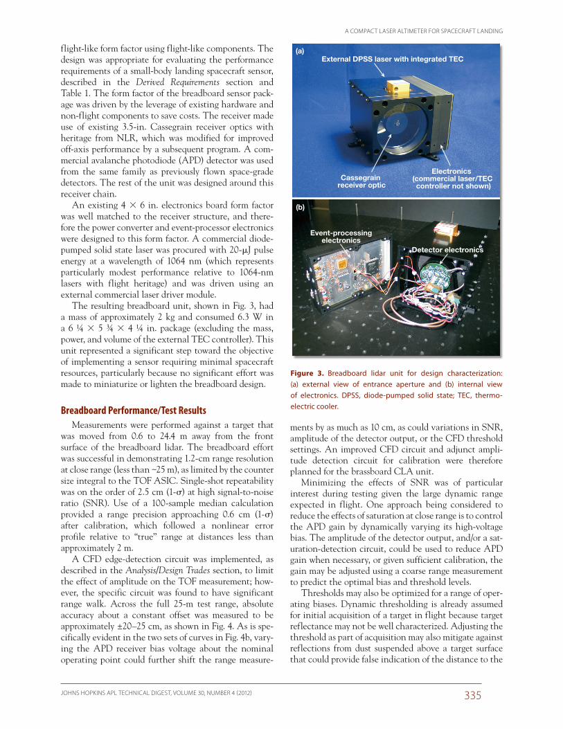
flight-like form factor using flight-like components. The design was appropriate for evaluating the performance requirements of a small-body landing spacecraft sensor, described in the Derived Requirements section and Table 1. The form factor of the breadboard sensor pack-age was driven by the leverage of existing hardware and non-flight components to save costs. The receiver made use of existing 3.5-in. Cassegrain receiver optics with heritage from NLR, which was modified for improved off-axis performance by a subsequent program. A com-mercial avalanche photodiode (APD) detector was used from the same family as previously flown space-grade detectors. The rest of the unit was designed around this receiver chain.
An existing 4 6 in. electronics board form factor was well matched to the receiver structure, and there-fore the power converter and event-processor electronics were designed to this form factor. A commercial diode-pumped solid state laser was procured with 20-mJ pulse energy at a wavelength of 1064 nm (which represents particularly modest performance relative to 1064-nm lasers with flight heritage) and was driven using an external commercial laser driver module.
The resulting breadboard unit, shown in Fig. 3, had a mass of approximately 2 kg and consumed 6.3 W in a 6 ¼ 5 ¾ 4 ¼ in. package (excluding the mass, power, and volume of the external TEC controller). This unit represented a significant step toward the objective of implementing a sensor requiring minimal spacecraft resources, particularly because no significant effort was made to miniaturize or lighten the breadboard design.
Breadboard Performance/Test ResultsMeasurements were performed against a target that
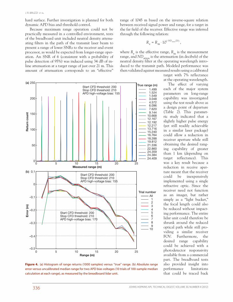
was moved from 0.6 to 24.4 m away from the front surface of the breadboard lidar. The breadboard effort was successful in demonstrating 1.2-cm range resolution at close range (less than ~25 m), as limited by the counter size integral to the TOF ASIC. Single-shot repeatability was on the order of 2.5 cm (1-s) at high signal-to-noise ratio (SNR). Use of a 100-sample median calculation provided a range precision approaching 0.6 cm (1-s) after calibration, which followed a nonlinear error profile relative to “true” range at distances less than approximately 2 m.
A CFD edge-detection circuit was implemented, as described in the Analysis/Design Trades section, to limit the effect of amplitude on the TOF measurement; how-ever, the specific circuit was found to have significant range walk. Across the full 25-m test range, absolute accuracy about a constant offset was measured to be approximately ±20–25 cm, as shown in Fig. 4. As is spe-cifically evident in the two sets of curves in Fig. 4b, vary-ing the APD receiver bias voltage about the nominal operating point could further shift the range measure-
External DPSS laser with integrated TEC
Cassegrain receiver optic
Electronics (commercial laser/TEC controller not shown)
(a)
Event-processingelectronics
Detector electronics
(b)
Figure 3. Breadboard lidar unit for design characterization: (a) external view of entrance aperture and (b) internal view of electronics. DPSS, diode-pumped solid state; TEC, thermo- electric cooler.
J. R. BRUZZI ET AL.
JOHNS HOPKINS APL TECHNICAL DIGEST, VOLUME 30, NUMBER 4 (2012)336
range of 1045 m based on the inverse-square relation between received signal power and range, for a target in the far field of the receiver. Effective range was inferred through the following relation:
10R Re m/ND 20– atten$= ^ h ,
where Re is the effective range, Rm is the measurement range, and NDatten is the attenuation (in decibels) of the neutral density filter at the operating wavelength intro-duced to the transmit path. Modeled performance was then validated against measured results using a calibrated
target with 7% reflectance at the operating wavelength.
The effect of varying each of the major system parameters on long-range capability was investigated using the test result above as a design point of departure (Table 2). This paramet-ric study indicated that a slightly higher pulse energy (yet still readily achievable in a similar laser package) could allow a reduction in receiver aperture while still obtaining the desired rang-ing capability of greater than 1 km (depending on target reflectance). This was a key result because a reduction in receive aper-ture meant that the receiver could be inexpensively implemented using a single refractive optic. Since the receiver need not function as an imager, but rather simply as a “light bucket,” the focal length could also be reduced without impact-ing performance. The entire lidar unit could therefore be shrunk around the reduced optical path while still pro-viding a similar receiver FOV. Furthermore, the desired range capability could be achieved with a photodetector responsivity available from a commercial part. The breadboard tests also provided insight into performance limitations that could be traced back
hard surface. Further investigation is planned for both dynamic APD bias and threshold control.
Because maximum range operation could not be practically measured in a controlled environment, tests of the breadboard unit included neutral density attenu-ating filters in the path of the transmit laser beam to present a range of lower SNRs to the receiver and event processor, as would be expected from longer-range oper-ation. An SNR of 6 (consistent with a probability of pulse detection of 95%) was induced using 34 dB of in-line attenuation at a target range of just over 21 m. This amount of attenuation corresponds to an “effective”
Start CFD threshold: 200Stop CFD threshold: 210APD high-voltage bias: 155
250(a)
(b)
200
150
100
50
0
0 5 10 15Range (m)
20 25
0 5 10 15Measured range (m)
20 25
Ret
urn
coun
t
0.1
0
–0.1
–0.2
–0.3
–0.4
–0.5
Err
or
(m)
Start CFD threshold: 200Stop CFD threshold: 210APD high-voltage bias: 155
Start CFD threshold: 200Stop CFD threshold: 210APD high-voltage bias: 170
1.499 1.524 1.549 3.048 4.572 6.096 7.620 9.14410.66812.16712.19212.21713.71615.24016.76418.28819.81221.33622.86024.35924.38424.409
True range (m)
All 1 2 3 4 5 6 7 8 9 10
Trial number
Figure 4. (a) Histogram of range returns (1000 samples) versus “true” range. (b) Absolute range error versus uncalibrated median range for two APD bias voltages (10 trials of 100-sample median calculation at each range), as measured by the breadboard lidar unit.

A COMPACT LASER ALTIMETER FOR SPACECRAFT LANDING
JOHNS HOPKINS APL TECHNICAL DIGEST, VOLUME 30, NUMBER 4 (2012) 337
all package is significantly smaller than any previously flown space-based lidar and consumes significantly less DC power for the measurement repetition rate achieved. The entire unit has a mass of 1.15 kg and a core volume of essentially a 4-in. cube, whereas the full envelope includ-ing the optics and mounting feet extends to 4.8 (W) 5.39 (L) 3.95 (H) in. Power consumption has yet to be characterized over a full range of baseplate temperatures but is roughly 12 W at ambient, dominated by the laser driver and associated temperature control electronics.
The lidar concept is intended not only to be efficient in terms of mass and power, but also inexpensive. A simple architecture and measurement scheme is imple-mented, and commercial optics and electronic compo-nents are used. The brassboard uses a modest-energy commercial laser source; however, the components and materials used within the flight laser will lever-age the investments of the many space missions that have already flown much higher-energy 1064-nm laser sources. (Numerous previous space-based lidars have even carried lasers with greater than three orders of magnitude higher pulse energy.)
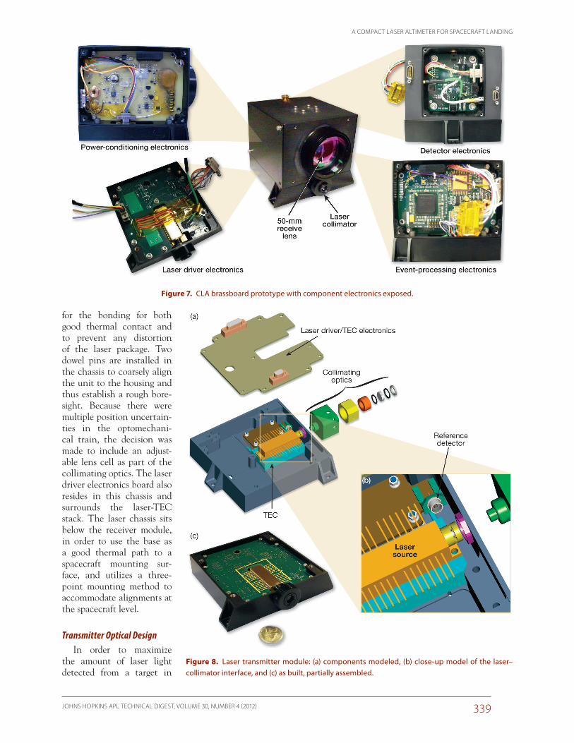
Transmitter ModuleThe laser transmitter, shown in Fig. 8, constitutes the
base of the CLA unit, providing the spacecraft mount-ing interface and a good heat transfer path. It houses the laser source, laser driver electronics, the required TEC and controlling electronics, and transmit beam collimat-ing optics. Given the relatively low-energy laser required for this application, the electronics are contained on a single 4 4 in. board, which surrounds the laser source
to specific design implementations. The package was consequently redesigned optically and electrically and miniaturized on the basis of the lessons learned in the breadboard characterization effort. A detailed descrip-tion of the resulting prototype CLA, as it was designed and built in brassboard form, follows.
BRASSBOARD PROTOTYPE DESIGN
Packaging ConceptThe brassboard CLA design is completely self-con-
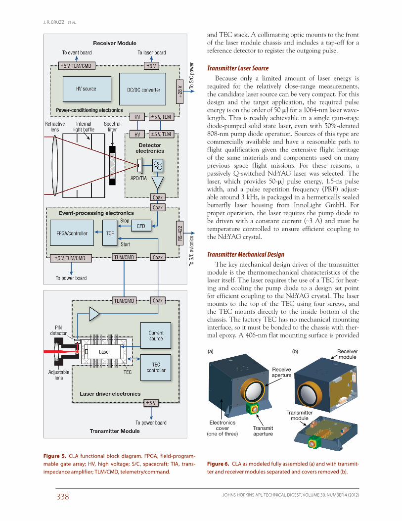
tained in one unit for ease of integration via a single mechanical interface, a single serial data interface, and a standard 28-V power bus connection. A block dia-gram of the unit is shown in Fig. 5. A biaxial optical design was chosen to separate the transmit path from the receive path so that the laser beam fully enters the receiver’s FOV only beyond a predetermined range. This helps avoid near-field backscatter that would saturate the detector and limit the lidar’s close-range operation. The brassboard unit contains two modules, transmitter and receiver, each having an optical, mechanical, and electronic aspect to its design. However, the majority of the structure and electronics resides within the receiver module. Given the biaxial optical design, the transmit-ter and receiver modules are designed to be separable, as shown in Fig. 6, enabling parallel development and test regimens. The physical architecture consists of a central optical chain surrounded by four electronics boards, as shown in Fig. 7, including the power conditioner, detec-tor, event processor, and laser driver boards. The over-
Table 2. Examination of maximum effective range capability relative to benchmark measurement
Impact of parameter change
Receiver FOV to transmitter
divergence overlap efficiency
Target reflectance
Pulse energy,
mJ
APD responsivity,
V/W
Total receiver diameter
(effective), mm
Effective range
capability, m
Benchmark (breadboard design point) 0.24 0.07 0.0211 200,000 77 1045.4
Effect of redesigning FOV to encom-pass full transmit spot
1 0.07 0.0211 200,000 77 2133.9
Effect of expected target reflectance 1 0.02 0.0211 200,000 77 1140.6
Effect of reducing receive aperture 1 0.02 0.0211 200,000 50 740.7
Effect of incorporating responsivity of space-grade APD
1 0.02 0.0211 770,000 50 1453.3
Effect of increasing laser energy 1 0.02 0.0500 770,000 50 2237.2
Effect of reverting to responsivity of commercial APD (brassboard design point)
1 0.02 0.0500 200,000 50 1140.2
Bold indicates the effective range meets the >1-km goal; italics indicate the effective range does not meet the >1-km goal.
J. R. BRUZZI ET AL.
JOHNS HOPKINS APL TECHNICAL DIGEST, VOLUME 30, NUMBER 4 (2012)338
and TEC stack. A collimating optic mounts to the front of the laser module chassis and includes a tap-off for a reference detector to register the outgoing pulse.
Transmitter Laser SourceBecause only a limited amount of laser energy is
required for the relatively close-range measurements, the candidate laser source can be very compact. For this design and the target application, the required pulse energy is on the order of 50 mJ for a 1064-nm laser wave-length. This is readily achievable in a single gain-stage diode-pumped solid state laser, even with 50%-derated 808-nm pump diode operation. Sources of this type are commercially available and have a reasonable path to flight qualification given the extensive flight heritage of the same materials and components used on many previous space flight missions. For these reasons, a passively Q-switched Nd:YAG laser was selected. The laser, which provides 50-mJ pulse energy, 1.5-ns pulse width, and a pulse repetition frequency (PRF) adjust-able around 3 kHz, is packaged in a hermetically sealed butterfly laser housing from InnoLight GmbH. For proper operation, the laser requires the pump diode to be driven with a constant current (~3 A) and must be temperature controlled to ensure efficient coupling to the Nd:YAG crystal.
Transmitter Mechanical DesignThe key mechanical design driver of the transmitter
module is the thermomechanical characteristics of the laser itself. The laser requires the use of a TEC for heat-ing and cooling the pump diode to a design set point for efficient coupling to the Nd:YAG crystal. The laser mounts to the top of the TEC using four screws, and the TEC mounts directly to the inside bottom of the chassis. The factory TEC has no mechanical mounting interface, so it must be bonded to the chassis with ther-mal epoxy. A 406-nm flat mounting surface is provided
Electronicscover
(one of three)Transmitaperture
Receiveaperture
Transmittermodule
Receivermodule
(a) (b)
Figure 6. CLA as modeled fully assembled (a) and with transmit-ter and receiver modules separated and covers removed (b).
Figure 5. CLA functional block diagram. FPGA, field-program-mable gate array; HV, high voltage; S/C, spacecraft; TIA, trans-impedance amplifier; TLM/CMD, telemetry/command.
A COMPACT LASER ALTIMETER FOR SPACECRAFT LANDING
JOHNS HOPKINS APL TECHNICAL DIGEST, VOLUME 30, NUMBER 4 (2012) 339
for the bonding for both good thermal contact and to prevent any distortion of the laser package. Two dowel pins are installed in the chassis to coarsely align the unit to the housing and thus establish a rough bore-sight. Because there were multiple position uncertain-ties in the optomechani-cal train, the decision was made to include an adjust-able lens cell as part of the collimating optics. The laser driver electronics board also resides in this chassis and surrounds the laser-TEC stack. The laser chassis sits below the receiver module, in order to use the base as a good thermal path to a spacecraft mounting sur-face, and utilizes a three-point mounting method to accommodate alignments at the spacecraft level.
Transmitter Optical DesignIn order to maximize
the amount of laser light detected from a target in
Figure 7. CLA brassboard prototype with component electronics exposed.
Figure 8. Laser transmitter module: (a) components modeled, (b) close-up model of the laser– collimator interface, and (c) as built, partially assembled.
J. R. BRUZZI ET AL.
JOHNS HOPKINS APL TECHNICAL DIGEST, VOLUME 30, NUMBER 4 (2012)340
C-mount threading to ease the attachment of neutral density filters during integration and test.
Transmitter Laser Driver ElectronicsThe laser driver electronics consist primarily of a
current driver and TEC controller. The electronics also houses the high-speed reference photodiode and pream-plifier used for detecting the rising edge of the outgoing laser pulse (although the brassboard design implements this circuit on a separate small electronics board mounted directly to the base of the transmitter chassis). The ref-erence detector signal is sent to the event-processing electronics to register the start of a range measurement. The use of high-efficiency DC/DC converters through-out the laser driver electronics results in minimal overall power consumption.
The laser current driver supplies current to the pump laser diode inside the laser head and is implemented as a constant current source, meaning that the current supplied is not affected by electrical variations in the laser diode. The driver is capable of sourcing current as high as 4.5 A and can be adjusted with a resolution of 10 mA. In order to protect the laser diode from current spikes, the current driver is implemented as a sequence of highly efficient DC/DC converters followed by a very accurate and fast linear regulator. The high-efficiency DC/DC converter precedes the linear regulator and con-verts the main 5-V power bus to a voltage slightly higher than the laser diode operational voltage. To maintain high efficiency, the voltage drop across the linear regula-tor is kept below 100 mV. The laser diode current and the voltage across the laser diode are monitored and available as telemetry.
The TEC driver consists of a high-efficiency voltage converter that supplies power to the TEC in order to heat or cool the laser diode. The temperature of the laser diode is measured through a thermistor internal to the butterfly laser package. The TEC control loop adjusts the power supplied from the converter to the TEC until the thermistor resistance reaches that of the required temperature. In addition, an error amplifier controls two pairs of ON/OFF complementary switches, which change the direction of the current flowing through the TEC, thereby selecting a cooling or heating mode of operation. The TEC is not sensitive to current spikes and therefore may be driven directly from an adjustable DC/DC converter, limiting energy waste to solely the converter loss. Parameters such as TEC voltage, TEC current, and laser diode and ambient temperatures are also monitored and available as telemetry.
Receiver ModuleThe receiver portion of the CLA mounts directly
on top of the laser transmitter module. The receiver module contains the receiving optics, photodetector,
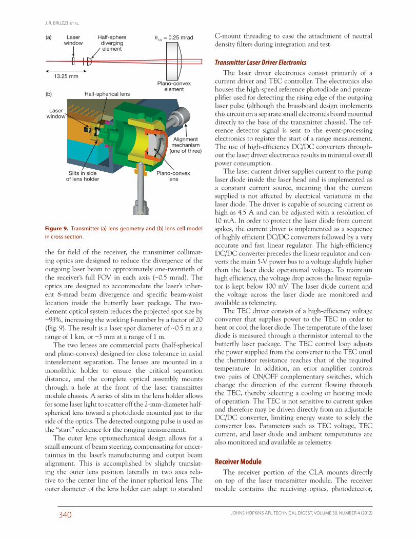
the far field of the receiver, the transmitter collimat-ing optics are designed to reduce the divergence of the outgoing laser beam to approximately one-twentieth of the receiver’s full FOV in each axis (~0.5 mrad). The optics are designed to accommodate the laser’s inher-ent 8-mrad beam divergence and specific beam-waist location inside the butterfly laser package. The two-element optical system reduces the projected spot size by ~93%, increasing the working f-number by a factor of 20 (Fig. 9). The result is a laser spot diameter of ~0.5 m at a range of 1 km, or ~3 mm at a range of 1 m.
The two lenses are commercial parts (half-spherical and plano-convex) designed for close tolerance in axial interelement separation. The lenses are mounted in a monolithic holder to ensure the critical separation distance, and the complete optical assembly mounts through a hole at the front of the laser transmitter module chassis. A series of slits in the lens holder allows for some laser light to scatter off the 2-mm-diameter half-spherical lens toward a photodiode mounted just to the side of the optics. The detected outgoing pulse is used as the “start” reference for the ranging measurement.
The outer lens optomechanical design allows for a small amount of beam steering, compensating for uncer-tainties in the laser’s manufacturing and output beam alignment. This is accomplished by slightly translat-ing the outer lens position laterally in two axes rela-tive to the center line of the inner spherical lens. The outer diameter of the lens holder can adapt to standard
Half-spherical lens
Laserwindow
Plano-convexlens
Alignmentmechanism
(one of three)
Slits in sideof lens holder
Half-spheredivergingelement
Plano-convexelement
Laserwindow
13.25 mm
�1/e = 0.25 mrad(a)
(b)
Figure 9. Transmitter (a) lens geometry and (b) lens cell model in cross section.
A COMPACT LASER ALTIMETER FOR SPACECRAFT LANDING
JOHNS HOPKINS APL TECHNICAL DIGEST, VOLUME 30, NUMBER 4 (2012) 341
which spillover of the reflected beam spot (relative to the detector area) would begin to detract from the detec-tor signal level. Given the biaxial optical design, how-ever, the overlap integral of the detector FOV and the reflected beam spot is even less at close range, thus better mitigating the saturation effect at touchdown distances. (At these extremely close ranges, even low amounts of scatter will be detected, albeit with an amount of cali-bration required to correct any nonlinear offsets from “true” range.)
Receiver Event-Processing ElectronicsThe event-processor board is a simplified version of
the event boards used in APL particle instruments. Its main task is to compute a TOF for laser start- and stop-pulse pairs. The start pulse is produced on the laser elec-tronics board (see Fig. 8). When the laser fires, a small amount of light is scattered sideways by the collimating lens. This flash is detected by a PIN photodiode refer-ence detector and amplified by the laser electronics. The stop pulse is generated from the laser return on the APD detector board, which is described in the Receiver Detector Electronics section. Based on the results of the breadboard test effort, an improved CFD ASIC is incorporated for stop-pulse timing. An amplitude mea-surement circuit is also included to allow for adaptive calibration using pulse amplitude in order to achieve the desired accuracy and precision.
The event-processor board uses a leading edge dis-criminator to produce a digital start pulse from the analog start pulse. The start timing does not suffer from walk, because the analog start-pulse does not vary sig-nificantly in amplitude. The analog stop pulse from the APD preamplifier is input to the CFD ASIC which, in turn, outputs a digital stop pulse. The digital start and
and an internal light baffle and provides the housing for the remainder of the electronics boards: event-pro-cessing electronics, detector electronics, and power-con-ditioning electronics. Therefore, external interfaces to the CLA are made through the receiver housing, which consists simply of two connectors: (i) a +28 VDC (nomi-nal) power input and (ii) a serial RS-422 telemetry and control interface. The electronics boards are located along the perimeter of the receiver optical path, each having its own access cover for ease of integration and test. Board interconnects are made via an internal har-nessing scheme, both within the receiver module and to the laser electronics below.
Receiver Mechanical DesignThe mechanical design of the receiver housing is rel-
atively simple. The drivers of the design were the size of the available “fixed” refractive lens and the optical focal length. Two side covers and an additional rear cover pro-vide access to all of the electronics. To accommodate alignment of the detector FOV with the transmit beam, the detector electronics position is adjustable using two pairs of removable micrometer stages (see Fig. 11). The manual micrometers translate the detector location in the “X” and “Y” planes. The “Z” location, or posi-tion relative to the focus, can be adjusted if necessary through the use of a shim behind the receiver lens. Once the detector is optimally positioned, it is then pinned into place, micrometers are removed, and the holes are plugged with threaded inserts. The receiver chassis attaches to the transmitter module with four screws and a mechanical shear lip to provide both coarse alignment with the transmitter and a light-tight interface.
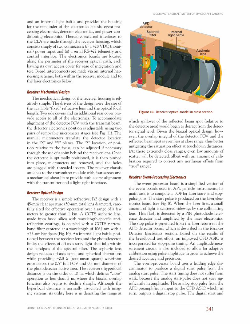
Receiver Optical DesignThe receiver is a simple refractive, F/2 design with a
45-mm clear aperture (50-mm total lens diameter), care-fully sized for effective operation over a range of a few meters to greater than 1 km. A COTS aspheric lens, made from fused silica with wavelength-specific anti-reflection coatings, is coupled with a COTS narrow-band filter centered at a wavelength of 1064 nm with a ±25-nm bandpass (Fig. 10). An internal light baffle, posi-tioned between the receiver lens and the photodetector, limits the effects of off-axis stray light that falls within the bandpass of the spectral filter. The aspheric lens design reduces off-axis coma and spherical aberrations while providing ~0.8 l (root-mean-square) wavefront error across the 0.5° full FOV and 0.8-mm diameter of the photodetector active area. The receiver’s hyper focal distance is on the order of 10 m, which defines “close” operation as less than 5 m, where the biaxial overlap function also begins to decline sharply. Although the hyperfocal distance is normally associated with imag-ing systems, its utility here is in denoting the range at
Spectral�lter
Asphericlens
Internallight baf�e
APDdetector
Asphericlens
Internallight baf�e
Spectral�lter
APDdetector
Figure 10. Receiver optical model in cross section.
J. R. BRUZZI ET AL.
JOHNS HOPKINS APL TECHNICAL DIGEST, VOLUME 30, NUMBER 4 (2012)342
flown as part of the Lunar Laser Ranging Instrument (LLRI) on the Indian Space Research Organisation’s (ISRO’s) Chandrayaan-1 spacecraft and is suitable for low-radiation-dose missions. It is straightforward, how-ever, to switch to a flight version by modifying the detec-tor preamp board to accommodate the slightly different flight package. The signal-processing circuitry would be unchanged with the exception of a few resistor values, and the detector board has enough unused area to make this change fairly straightforward.
When a laser pulse return illuminates the photode-tector, the transimpedance amplifier outputs a narrow voltage pulse with an approximately Gaussian shape and rise and fall times of 2 ns, limited by the transimped-ance amplifier bandwidth. This pulse is passed through a filter that is matched to the detector output pulse to improve the SNR. The filtered pulse is amplified and shaped to have a longer tail, as dictated by the CFD used in the event-processing electronics.
Receiver Power-Conditioning ElectronicsThe power-conditioning electronics consists of two
sections: the main power converter and a low-power, high-voltage source. The power converter accepts pri-mary power from the spacecraft bus and converts it to the +5-V and –5-V secondary power sources used by electronics throughout the unit. The secondary sources are galvanically isolated from the primary feed, which is nominally +28 VDC, although the converter accommo-dates an input range between +18 and +40 V. For sim-plicity, a radiation-hard COTS module is used, although higher efficiency could be achieved using a custom-designed converter for this application.
The high-voltage source provides an adjustable bias to the detector board, allowing for fine tuning of the APD receiver gain, as described in the Breadboard Performance/Test Results section. Both its design and hardware were leveraged from recent Juno spacecraft instrument designs. A variable DC voltage is converted to alternating current and then raised by a transformer to a higher alternating current voltage. A four-stage multiplier raises the voltage further and rectifies it to a DC level. The filter which follows attenuates the resid-ual switching noise to less than 50 mV (peak to peak). A control loop is used to tightly maintain the desired high-voltage value. The output may be controlled in 1-V steps between 0 and 500 V, while overall power consumption of the high-voltage source is limited to less than 50 mW.
BRASSBOARD INTEGRATION
IntegrationAs mentioned previously, the CLA allows for inde-
pendent transmitter and receiver development. Trans-
stop pulses are applied to a time-to-digital converter ASIC. The time-to-digital converter provides an 11-bit code and a valid event flag to a field-programmable gate array (FPGA). The scale of the least significant bit (LSB) of the time-to-digital converter is controlled by a calibration clock that is provided by the FPGA through the following relation, so that a variety of measurement distances can be accommodated:
DTLSB = Tcal/512 ,
where Tcal is the period of the calibration clock and DTLSB is the time measurement resolution. A 25-MHz calibration clock is used for ranges less than 24 m cor-responding to the finest round-trip single shot resolu-tion of 2.34 cm (1.17-cm target range). The calibration clock is divided down from the 50-MHz FPGA clock, so its period can be adjusted in the FPGA to increase the LSB for longer ranges. For a range of 1 km, a round-trip single shot resolution of 98.4 cm (49.2-cm target range) is obtained with a calibration clock frequency of 595 kHz. The digital start and stop pulses are also wired to the FPGA to allow it to determine the appropriate range scale and range gating.
In addition to the TOF processing, the event-pro-cessor board detects and digitizes the amplitude of the analog stop pulse so that compensation for saturation and multiple returns can be performed. The event board also monitors housekeeping data (temperatures, cur-rents, and voltages) and implements a command and telemetry RS-422 serial interface. Every serial command is answered by a serial output telemetry response. Typi-cally, commands and responses are exchanged at 10 Hz. A serial command sets various parameters, such as high voltage levels, thresholds, number of returns to pro-cess, and so forth. A common response would include a subset of the housekeeping data, a median of a selected number of returns, and some statistics such as the mini-mum, maximum, and number of missing returns.
Receiver Detector ElectronicsThe CLA uses a red-enhanced silicon APD hybrid
manufactured by PerkinElmer. This hybrid hosts the APD, which is biased in the linear gain region at a reverse bias between 275 and 425 V, and a transimped-ance amplifier to convert the APD photocurrent to a voltage pulse. The bias may be adjusted to reduce the effect of saturation on the CFD response at close range. The detector has an active area with 0.8 mm diameter, a responsivity of 200 kV/W at 1064 nm, and a rise time of 2 ns. The CLA brassboard uses a commercial detector similar to the flight versions used by NLR and several other space-based instruments, including the Mercury Laser Altimeter (MLA) flying on the MESSENGER (MErcury Surface, Space ENvironment, GEochemistry, and Ranging) spacecraft. The commercial detector has
A COMPACT LASER ALTIMETER FOR SPACECRAFT LANDING
JOHNS HOPKINS APL TECHNICAL DIGEST, VOLUME 30, NUMBER 4 (2012) 343
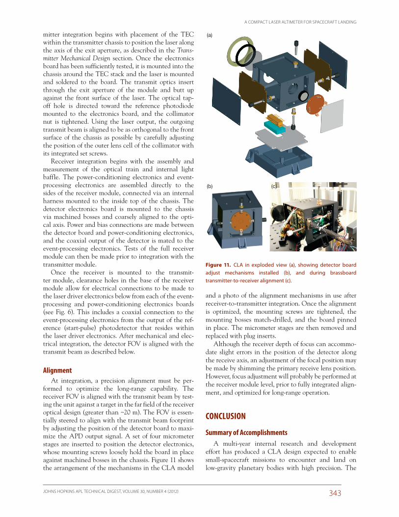
and a photo of the alignment mechanisms in use after receiver-to-transmitter integration. Once the alignment is optimized, the mounting screws are tightened, the mounting bosses match-drilled, and the board pinned in place. The micrometer stages are then removed and replaced with plug inserts.
Although the receiver depth of focus can accommo-date slight errors in the position of the detector along the receive axis, an adjustment of the focal position may be made by shimming the primary receive lens position. However, focus adjustment will probably be performed at the receiver module level, prior to fully integrated align-ment, and optimized for long-range operation.
CONCLUSION
Summary of AccomplishmentsA multi-year internal research and development
effort has produced a CLA design expected to enable small-spacecraft missions to encounter and land on low-gravity planetary bodies with high precision. The
mitter integration begins with placement of the TEC within the transmitter chassis to position the laser along the axis of the exit aperture, as described in the Trans-mitter Mechanical Design section. Once the electronics board has been sufficiently tested, it is mounted into the chassis around the TEC stack and the laser is mounted and soldered to the board. The transmit optics insert through the exit aperture of the module and butt up against the front surface of the laser. The optical tap-off hole is directed toward the reference photodiode mounted to the electronics board, and the collimator nut is tightened. Using the laser output, the outgoing transmit beam is aligned to be as orthogonal to the front surface of the chassis as possible by carefully adjusting the position of the outer lens cell of the collimator with its integrated set screws.
Receiver integration begins with the assembly and measurement of the optical train and internal light baffle. The power-conditioning electronics and event-processing electronics are assembled directly to the sides of the receiver module, connected via an internal harness mounted to the inside top of the chassis. The detector electronics board is mounted to the chassis via machined bosses and coarsely aligned to the opti-cal axis. Power and bias connections are made between the detector board and power-conditioning electronics, and the coaxial output of the detector is mated to the event-processing electronics. Tests of the full receiver module can then be made prior to integration with the transmitter module.
Once the receiver is mounted to the transmit-ter module, clearance holes in the base of the receiver module allow for electrical connections to be made to the laser driver electronics below from each of the event-processing and power-conditioning electronics boards (see Fig. 6). This includes a coaxial connection to the event-processing electronics from the output of the ref-erence (start-pulse) photodetector that resides within the laser driver electronics. After mechanical and elec-trical integration, the detector FOV is aligned with the transmit beam as described below.
AlignmentAt integration, a precision alignment must be per-
formed to optimize the long-range capability. The receiver FOV is aligned with the transmit beam by test-ing the unit against a target in the far field of the receiver optical design (greater than ~20 m). The FOV is essen-tially steered to align with the transmit beam footprint by adjusting the position of the detector board to maxi-mize the APD output signal. A set of four micrometer stages are inserted to position the detector electronics, whose mounting screws loosely hold the board in place against machined bosses in the chassis. Figure 11 shows the arrangement of the mechanisms in the CLA model
(b) (c)
(a)
Figure 11. CLA in exploded view (a), showing detector board adjust mechanisms installed (b), and during brassboard transmitter- to-receiver alignment (c).
J. R. BRUZZI ET AL.
JOHNS HOPKINS APL TECHNICAL DIGEST, VOLUME 30, NUMBER 4 (2012)344
will put into practice the calibration circuits designed into the CLA to correct for this effect and will allow a determination of the absolute accuracy achievable with the CLA at close range. The effects of temperature and suspended dust on sensor performance are also likely to be pursued for the expected environment of upcoming candidate missions.
The short-to-mid-range CLA is a critical element of a dual-band surface-relative navigation suite of sensors that enables autonomous small-body landing. It provides APL with a viable and cost-effective technology base in terms of performance, mass, and power for proposing competitive Discovery- and New Frontiers-class missions encountering small bodies. The inherent technology extends to scientific instruments with longer standoff ranges and may alternatively be integrated with a compact imager for short-range tracking and proximity operations about resident space objects.
ACKNOWLEDGEMENTS: This work was performed under the support of APL’s Civilian Space Internal Research and Development Program, largely as part of the Instrument Development Program. The team would like to thank Kevin Heffernan and Robert Gold for their support of this effort, Olivier Barnouin and James Kaidy for their mission- and system-level input, and Kevin Baldwin, David Brown, Gordon Maahs, Nick Paschalidis, William Torruellas, and Raymond Sova for their eager technical assistance and advice throughout the effort.
REFERENCES 1Kaidy, J., McGee, T., Criss, T., Heyler, G., Shyong, W., and Guzman,
J., “Spacecraft Precision Landing System for Low Gravity Bodies,” Proc. 33rd Annual AAS Rocky Mountain Guidance and Control Conf., Breckenridge, CO, paper 10-P02 (2010).
2Kaidy, J., McGee, T., Criss, T., Heyler, G., and Shyong, W., “Deimos Precision Lander Guidance, Navigation and Control Design,” in Proc. 61st International Astronautical Congress, Prague, Czech Republic, paper IAC-10.C1.6.7 (2010).
3Cole, T. D., “NEAR Laser Rangefinder: A Tool for the Mapping and Topologic Study of Asteroid 433 Eros,” Johns Hopkins APL Tech. Dig. 19(2), 142–157 (1998).
4Boone, B. G., Strohbehn, K., Kluga, B. E., Baldwin, K. C., Bruzzi, J. R., et al., “Dual-Band Spacecraft Sensor Suite for Lunar and Small-Body Landing,” in Laser Radar Technology and Applications XII, Proc. SPIE, Vol. 6550, M. D. Turner and G. W. Kamerman (eds.), SPIE, Belling-ham, WA (2007).
5Hashimoto, T., Kubota, T., and Mizuno, T., “Light Weight Sensors for the Autonomous Asteroid Landing of MUSES-c Mission,” Acta Astronautica 52(2–6), 381–388 (2003).
6Paschalidis, N. P., Stamatopoulos, N., Karadamoglou, K., Kottaras, G., Paschalidis, V., et al., “A CMOS Time of Flight System on a Chip for Spacecraft Instrumentation,” IEEE Trans. Nucl. Sci. 49(3), 1156–1163 (2002).
analysis and breadboard test phases have demonstrated the functionality and preliminary performance and ulti-mately informed the redesign and repackaging of a flight-like brassboard prototype. The performance objectives, which are distinct from those of heritage space-based lidars, are expected to be achieved, namely: high range resolution and accuracy, fast update rates, and accom-modation for the wide dynamic range expected at target close approach. The CLA is extremely compact, con-tained largely within the volume of a 4-in. cube, and requires minimal mass and power resources from the spacecraft platform.
Recent Progress and Next StepsInitial tests of the complete brassboard unit were per-
formed throughout 2011, including a series of aircraft- based flight tests. Vibration tests were successfully completed in advance of measurements made aboard a Cessna Turbo Skylane (T182) fixed-wing aircraft. This flight platform provided an opportunity to dem-onstrate the CLA at its expected long-range capabil-ity, which would otherwise only be inferred through close-range testing.
A maximum range greater than 1.3 km was consistently measured over a ground terrain that included desert mountains as well as crops; this range was limited only by an electronics setting that was not adjustable in flight (and was not limited by receiver sensitivity). Therefore, range capability is expected to be still greater for targets of similar reflectance. However, further characterization of the vegetation reflectance is required to deduce the maximum range capability expected for the dark celestial targets ultimately of interest. Long-range accuracy will also be characterized by using the onboard global positioning system (GPS) and inertial measurement unit (IMU) data recorded during CLA measurement periods; the data will be used to correlate the CLA measurements with a high-resolution digital elevation map that exists for the test region.
Close-range functionality and precision were also verified indoors from a range of 100 m to less than 1 m by using a calibrated reflectance target (7%). With an appropriate high-voltage bias setting, precision was measured to be around 1 cm (root mean square). Uncalibrated range accuracy was improved for the CLA relative to that of the breadboard lidar unit; however, some range “walk” remained because of the wide variation of receive pulse amplitude with lidar-target separation distance, particularly when operating at lower detector bias voltages. Additional planned tests
A COMPACT LASER ALTIMETER FOR SPACECRAFT LANDING
JOHNS HOPKINS APL TECHNICAL DIGEST, VOLUME 30, NUMBER 4 (2012) 345
Jonathan R. Bruzzi is the Principal Investigator of the APL CLA effort and was responsible for the system design and project management of the project. Mr. Bruzzi is a member of the Senior Professional Staff in the Space Department’s RF Engineering Group. He specializes in RF and optical communications systems and technologies. Kim Strohbehn is the Co-Investigator of the APL CLA effort and was also responsible for the event-processing and detector electronics. He is a member of the Principal Professional Staff in the Space Department’s Space Science Instrumen-tation Group. His primary interest is in space and astronomical instru-mentation. Bradley G. Boone is a Principal Professional Staff physicist in the Space Department’s RF Engineering Group and provided system-level performance requirements as Principal Investigator of the dual-band testbed effort. He has worked at APL in electro-optics for 34 years, sup-porting various active systems developments in laser communications and laser radar, in addition to prior work in advanced missile guidance, signal processing, superconducting devices, RF and optical sensors, and pattern-recognition systems. Samuel Kerem is a member of the Senior Professional Staff in the Space Department’s Space Science Instrumentation Group and was responsible for the laser driver and power converter electronics as part of this effort. Before joining APL, he worked for Corvis Corporation designing equipment for optical telecommunications. Russell S. Layman is a mechanical engineering designer and member of the Associate Pro-fessional Staff in the Space Department’s Space Science Instrumentation Group. He was responsible for the mechanical design and fabrication of the CLA breadboard and brassboard packages. He has designed numerous APL spacecraft and payloads, including the recent STEREO spacecraft. Matthew W. Noble is a member of the Senior Professional Staff in the
Space Department’s Space Science Instrumentation Group and has several years of experience in optical design and instrumentation. He was responsible for the optical design and testing of the CLA. He has designed optical systems for NASA sounding rocket programs and served as a test and integration field engineer on APL projects. His primary inter-ests are in space-borne imaging instrumentation. For further information on the work reported here, contact Jonathan Bruzzi. His e-mail address is [email protected].
The Authors
Kim StrohbehnJonathan R. Bruzzi
Bradley G. Boone
Samuel Kerem
Matthew W. Noble
Russell S. Layman
The Johns Hopkins APL Technical Digest can be accessed electronically at www.jhuapl.edu/techdigest.