Embed Size (px)
Citation preview
1
Department of Mechanical Engineering
For First year B.E./B.Tech Students Compiled by, Department of Mechanical & Civil Engineering Chettinad College of Engineering & Technology, Karur.
Basic Civil and Mechanical Engineering

2
3
A – CIVIL ENGINEERING
UNIT I SURVEYING AND CIVIL ENGINEERING MATERIALS 15
Surveying: Objects – types – classification – principles – measurements of
distances– angles – leveling – determination of areas – illustrative examples.
Civil Engineering Materials: Bricks – stones – sand – cement – concrete – steel sections.
UNIT II BUILDING COMPONENTS AND STRUCTURES 15
Foundations: Types, Bearing capacity – Requirement of good foundations.
Superstructure: Brick masonry – stone masonry – beams – columns – lintels –
roofing – flooring – plastering – Mechanics – Internal and external forces – stress – strain–
elasticity – Types of Bridges and Dams – Basics of Interior Design and Land scaping.
TOTAL: 30 PERIODS
B – MECHANICAL ENGINEERING
UNIT III POWER PLANT ENGINEERING 10
Introduction, Classification of Power Plants – Working principle of steam, Gas,
Diesel, Hydro-electric and Nuclear Power plants – Merits and Demerits – Pumps and
turbines – working principle of Reciprocating pumps (single acting and double acting)–
Centrifugal Pump.
UNIT IV I C ENGINES 10
Internal combustion engines as automobile power plant – Working principle of Petrol and
Diesel Engines – Four stroke and two stroke cycles – Comparison of four stroke and two
stroke engines – Boiler as a power plant.
UNIT V REFRIGERATION AND AIR CONDITIONING SYSTEM 10
Terminology of Refrigeration and Air Conditioning. Principle of vapour compression and
absorption system – Layout of typical domestic refrigerator – Window and Split type room
Air conditioner.

4
5
Civil Engineering

6
7
UNIT – I SURVEYING & CIVIL ENGINEERING MATERIALS
Physical properties Bulk density Chemical resistances Coefficient of softening Densities Density index Durability Porosity Specific heat Thermal conductivity Thermal capacity Water absorption Permeability
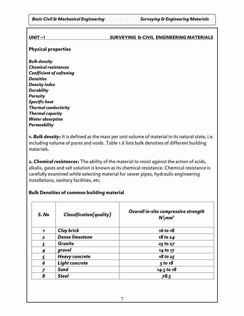
1. Bulk density: It is defined as the mass per unit volume of material in its natural state, i.e. including volume of pores and voids. Table 1.6 lists bulk densities of different building materials. 2. Chemical resistances: The ability of the material to resist against the action of acids, alkalis, gases and salt solution is known as its chemical resistance. Chemical resistance is carefully examined while selecting material for sewer pipes, hydraulic engineering installations, sanitary facilities, etc. Bulk Densities of common building material
S. No Classification(quality)
Overall in-situ compressive strength
N\mm2
1 Clay brick 16 to 18 2 Dense limestone 18 to 24 3 Granite 25 to 27 4 gravel 14 to 17 5 Heavy concrete 18 to 25 6 Light concrete 5 to 18 7 Sand 14.5 to 18 8 Steel 78.5
Basic Civil & Mechanical Engineering Surveying & Engineering Materials
8
3. Coefficient of softening: It is the ratio of compressive strength of material saturated with water to that in dry state. Materials having coefficient of softening more than or equal to 0.8 are referred to as the water –resisting materials.
4. Density: It is defined as the mass per unit volume of the material in its homogeneous state, i.e. neglecting the volume of pores and voids.
5. Density index: The ratio of bulk density of the material to its density is known as its density index. Thus, it denotes the degree to which its volume is filled up with solid matter. Density index for most of the building materials is less than unity.
6. Durability: The property of a material to resist the combined action of atmospheric and other factors is known as its durability. The life and maintenance cost of any structure depends upon the durability of the materials which it is composed of.
7. Porosity: The degree by which the volume of material is occupied by pores is termed as porosity. It is the ratio of volume of voids to the total volume of the specimen.
8. Specific heat: The term specific heat indicates the quantity of heat (ex-pressed in kilocalories) required to heat one N of material by one degree centigrade.
9. Thermal conductivity: Thermal conductivity of a material is defined as the amount of heat in kilocalories, that will flow through a unit area of the material with unit thickness in unit time and when the difference of temperature on its faces is also unity. The reciprocal of thermal conductivity of a material is termed as its thermal resistively.
10 Thermal capacities: The property by which the material absorbs heat is thermal as its termed as its thermal capacity. It is obtained by the following equation
T =H/(M (t1-t2) Where T = Thermal capacity in J\N*C H = Quantity of heat required to increase the temperature of a material from t1 to t2 in J M = mass of material in T1- T2 = Temperature difference of material before and after heating in * C
11. Water absorption: The ability of a material to absorb and retain water is termed as its water is absorption. It is expressed either as percentage of weight or percentage of volume of dry material. It mainly depends on the bulk den city and porosity of the material. 12. Permeability: The capacity of a material to allow water to pass through it under pressure is referred as its permeability. It denotes the quantity of water that will pass through a unit cross- sectional area of material in one hour at constant pressure.
Basic Civil & Mechanical Engineering Surveying & Engineering Materials
9
Mechanical properties The various mechanical properties of building material are as follows.
� Abrasion � Elasticity � Plasticity � Strength � Impact strength � Wear � Fatigue � Hardness � Brittleness � Ductility � Malleability � Toughness
Abrasion: It is the property of a material by which it resists the action of moving load. It is found by dividing the section, before and after abrasion with the area of abrasion.
Elasticity: The property by which a material regains its original shape and position after the removal of external load is known as elasticity.
Plasticity: It is the property of a material, by which no deformation vanishes, when it is relieved from the external load.
Strength: The ability of a material to resist failure under the action of external loads to which a material is commonly subjected to are compression, tension and bending. The corresponding strength is obtained by dividing the ultimate load with the cross-sectional area of the specimen.
Impact strength: It is defined as the quantity of work required to cause failure per unit of its volume. Thus, the impact strength indicates the toughness of the material.
Wear: The failure of a material under the combined actions of abrasion and impact is known as its wear. It is usually expressed as a percentage of loss in weight and it is very important to decide the suitability of a material for use of road surfaces, railway ballast, etc.
Fatigue: When the materials are subjected to repetitive fluctuating stress, they will fail at a stress much lower than that required to cause fracture under steady loads. This property is known as fatigue.
Brittleness: A material is said to be brittle when it cannot be drawn into a wire by tension. A brittle material fails suddenly under pressure without appreciable deformation preceding the failure. Concrete, glass, cast-iron, rock materials, etc. are some of the examples of brittle materials.
Basic Civil & Mechanical Engineering Surveying & Engineering Materials
10
Hardness: It is the ability of a material to resist penetration by a harder body. It plays an important role in deciding the workability and use of a material for floors and road surfaces. For stone materials, hardness can be determined with the help of Mohr’s scale of hardness. It is a list of ten materials arranged in the order of increasing hardness as shown in table 1.7. The leave of hardness of a material lies between the hard nesses of material, the one which scratches and the other which is scratched by the material to be tested.
Ductility: It is a property of a material by which it can be drawn into a wire by tension.
Malleability: The property by which a material can be uniformly extended in a direction without rupture is known as malleability. This property finds its applications in many operations such as forging, hot rolling, etc.
Toughness: Toughness is the property of a material that enables it to absorb energy with out fracture. This property is useful in shock loading.
1.1. Introduction
Surveying is the art of determining the relative position of points on, above or below the earth surface by direct or indirect measurements of distance, direction and elevation. 1.2. Objectives:
• The object of survey is to prepare the map or plan, so that it may represent the area on a horizontal plane. A plane or map is the horizontal projection of an area and shows only horizontal distances of the points.
• Vertical distances between the points are however shown b y contour lines or some other methods.
1.3. Purposes of surveying:
1. To produce up to date engineering plans of the areas in which work is going to be carried out which would be helpful for the design purpose.
2. To determine the required areas and volumes 0f land materials needed during construction.
3. To ensure the construction takes place in the correct relative and absolute position on the ground.
4. To record the final position of the construction including any design changes. 5. To provide permanent control points from which particularly important projects
can be surveyed.
Basic Civil & Mechanical Engineering Surveying & Engineering Materials
11
1.4. Primary division of surveying:
1.4.1. Plane surveying:
• In this type of surveying the mean surface of the earth is considered as a plane.
• All triangles formed by survey lines are considered as plane triangles in which small portions of earth surface are taken into account and spherical shape is neglected.
1.4.2. Geodetic surveying:
• Survey is which the shape (curvature) of the earth surface is taken in the account a higher degree of precision is exercised in linear and angular measurement is tanned as Geodetic Survey.
• A line connecting two points is regarded as an arc. Such surveys extend over large areas.
1.4.3. Principles of surveying:
Surveying is Location of a point by measurement from other points of reference and Working from whole to part.
1.5. Classification of surveying: 1.5.1. Classification based on the field Survey I. Land surveying: a. Topographical survey: The purpose is to gather survey data about the natural and man – made features of the land. b. Cadastral Survey: this is carried out to mark the boundaries of a land located within the city municipality, etc., c. City survey: This is made in connection with the construction of streets, water supply systems, sewers and other works. ii. Marine survey: It deals with bodies of water for purpose of navigation, harbor works. iii. Astronomical Survey: This carried out to understand the nature and the behavior of the heavily objects such as sun or any fixed star.
Basic Civil & Mechanical Engineering Surveying & Engineering Materials
12
1.5.2. Classification based on object of survey i. Engineering survey: to determination of quantities or to affords sufficient data for designing of engineering works such as roads and reservoirs. ii. Military survey: this is used for determining points of strategic importance. iii. Mine survey: this is exploding the mineral wealth. iv. Geological survey: This is used for determining the strata for earth’s crust. v. Archeological survey: This is used for unearthing relics of Antiquity.
1.5.3. Classification based on Instruments used
� Chain surveying
� Theologize surveying
� Plane table surveying
� Tachometric surveying
� Aerial surveying
� Photographic surveying.
1.5.4. Classification based on methods employed:
� Traverse surveying
� Triangulation surveying.
1.6. MEASUREMENT OF DISTANCES:
The distance between two points on the surface of earth can be determined by two methods: i. direct method, ii. Computative method
� Direct method: distances measured using tapes, chains etc.
� Computative method: Distance measured by using Tachometry, Triangulation.
Basic Civil & Mechanical Engineering Surveying & Engineering Materials
13
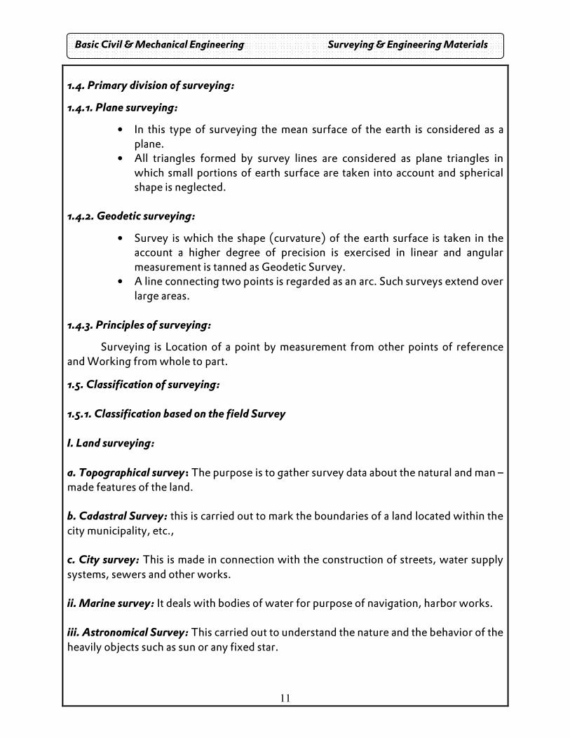
1.6.1. Chain surveying:
A. Linear measurements.
Principle: to provide a skeleton of frame
work consisting of a number of connected
triangles. The triangles are plotted from
the length of its sides, measured in the
field. The frame work consists of
equilateral triangles.
1.6.1.1. Terms used in Chain surveying:
Survey station: It is the main point on the chain line. Which can be at the beginning or at the end, these are called Main stations.
Subsidiary station: These are the station points which can be selected anywhere on the chain line for running the auxiliary line. It is also called as Tie station.
Base line: It is the longest of the main survey lines. This line is the main reference line for fixing the positions of various stations and also to fix the direction of the other lines.
Check line: It is used in the field in order to check the accuracy of the measurements made.
Survey lines:
The lines joining the main survey stations are called the survey lines. There are three types of survey lines, Base line, Check line and Tie line.
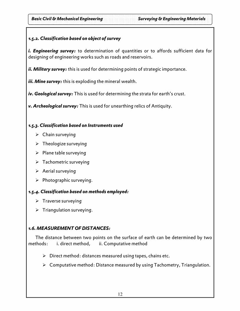
Tie line: The chain line joining the tie stations and subsidiary stations is called so. Off set:
• While survey is carried out, important details, such as boundaries, fences, buildings and towers are located with respect to main chain lines by means of lateral measurements.
• The two types of offsets show in figure, they are perpendicular and oblique offset.
Basic Civil & Mechanical Engineering Surveying & Engineering Materials
14
]
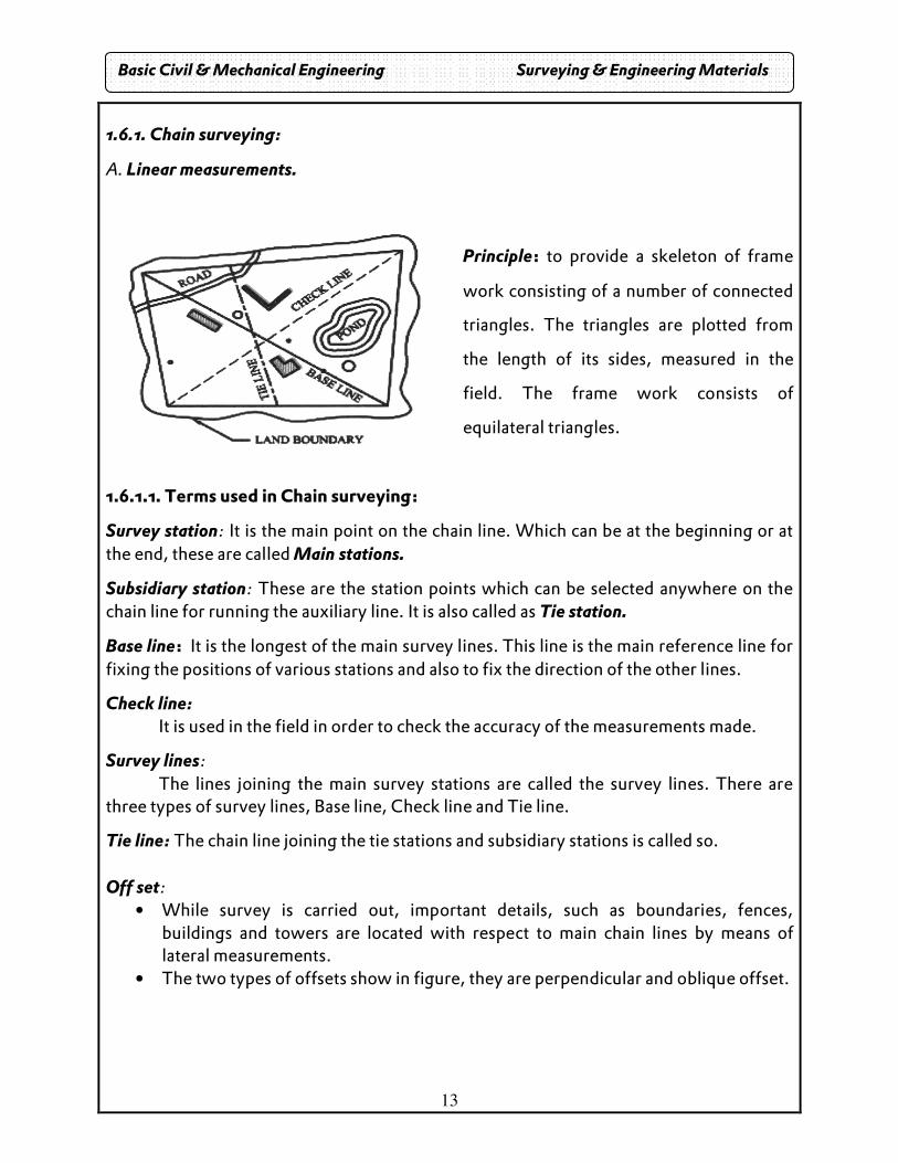
1.6.1.2. Compass • This instrument essentially consists of a freely suspended magnetic needle on a
pivot, which can move over graduated scale. • In addition to the above, it has an object vane and an eye vane which will be useful
to get the line of sight. • This instrument will be supported by a tripod stand while taking observations. • The two types of compass are : i. Prismatic compass and ii. Surveyors compass.
i. Prismatic compass • It is the most suitable type of rough surveys where speed is very important rather
than accuracy. • It is commonly used for the preliminary survey for a road, railway, military
purposes, a rough traverse etc. • The result from compass observation may be unrealistic in places where there is
more local attraction due to magnetic rock or iron ore deposits. • Fig shows the different parts of a prismatic compass.
Basic Civil & Mechanical Engineering Surveying & Engineering Materials
15
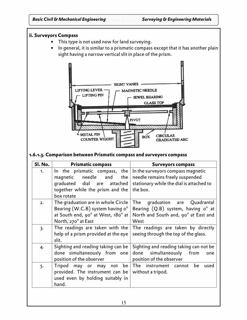
ii. Surveyors Compass • This type is not used now for land surveying. • In general, it is similar to a prismatic compass except that it has another plain
sight having a narrow vertical slit in place of the prism.
1.6.1.3. Comparison between Prismatic compass and surveyors compass
Sl. No. Prismatic compass Surveyors compass 1. In the prismatic compass, the
magnetic needle and the graduated dial are attached together while the prism and the box rotate
In the surveyors compass magnetic needle remains freely suspended stationary while the dial is attached to the box.
2. The graduation are in whole Circle Bearing (W.C.B) system having 0o at South end, 90o at West, 180o at North, 270o at East
The graduation are Quadrantal Bearing (Q.B) system, having 0o at North and South and, 90o at East and West
3. The readings are taken with the help of a prism provided at the eye slit.
The readings are taken by directly seeing through the top of the glass.
4. Sighting and reading taking can be done simultaneously from one position of the observer
Sighting and reading taking can not be done simultaneously from one position of the observer
5. Tripod may or may not be provided. The instrument can be used even by holding suitably in hand.
The instrument cannot be used without a tripod.
Basic Civil & Mechanical Engineering Surveying & Engineering Materials
16
1.6.1.4. Bearing:
Bearing is the horizontal angle between the reference meridian and survey line. It is measured in the clockwise direction. Bearings are classified into different types. They are
True Bearing Magnetic Bearing Whole Circle Bearing (W.C.B) Reduced Bearing (R.B) Fore Bearing (F.B) Back Bearing (B.B)
1. True Bearing
• True bearing of a line is the horizontal angle which makes with true meridian through one angle of the extremities of the line, measured always in the clockwise direction.
• The range of measurement is from 0o to 360o.
2. Magnetic Bearing
• The magnetic bearing of a line is the horizontal angle which makes with the magnetic meridian passing through one of the extremities of the line, measured always in the clockwise direction.
• The measuring range is from 0o to 360o.
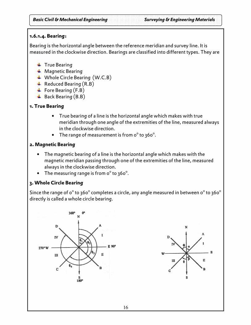
3. Whole Circle Bearing
Since the range of 0o to 360o completes a circle, any angle measured in between 0o to 360o directly is called a whole circle bearing.
Basic Civil & Mechanical Engineering Surveying & Engineering Materials
17
4. Reduced Bearing or Quadrantal Bearing
In this system, the bearing of a line is measured eastward or westward from North or south whichever is nearer.
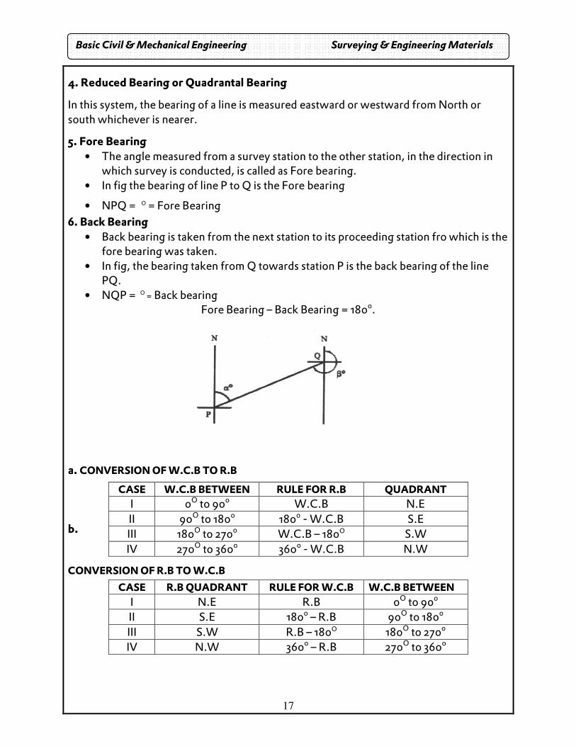
5. Fore Bearing • The angle measured from a survey station to the other station, in the direction in
which survey is conducted, is called as Fore bearing. • In fig the bearing of line P to Q is the Fore bearing
• NPQ = O = Fore Bearing
6. Back Bearing • Back bearing is taken from the next station to its proceeding station fro which is the
fore bearing was taken. • In fig, the bearing taken from Q towards station P is the back bearing of the line
PQ. • NQP = O = Back bearing
Fore Bearing – Back Bearing = 180o.
a. CONVERSION OF W.C.B TO R.B b.
CONVERSION OF R.B TO W.C.B
CASE W.C.B BETWEEN RULE FOR R.B QUADRANT
I 0O to 90o W.C.B N.E II 90O to 180o 180o - W.C.B S.E III 180O to 270o W.C.B – 180O S.W IV 270O to 360o 3600 - W.C.B N.W
CASE R.B QUADRANT RULE FOR W.C.B W.C.B BETWEEN
I N.E R.B 0O to 90o II S.E 180o – R.B 90O to 180o III S.W R.B – 180O 180O to 270o IV N.W 3600 – R.B 270O to 360o
Basic Civil & Mechanical Engineering Surveying & Engineering Materials
18
Problems:
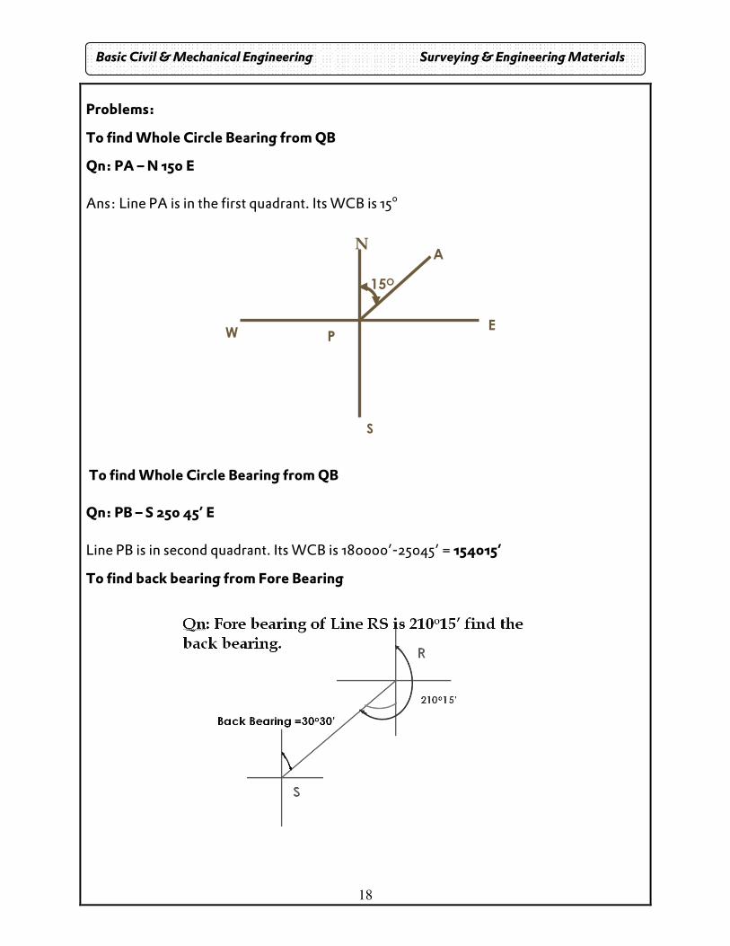
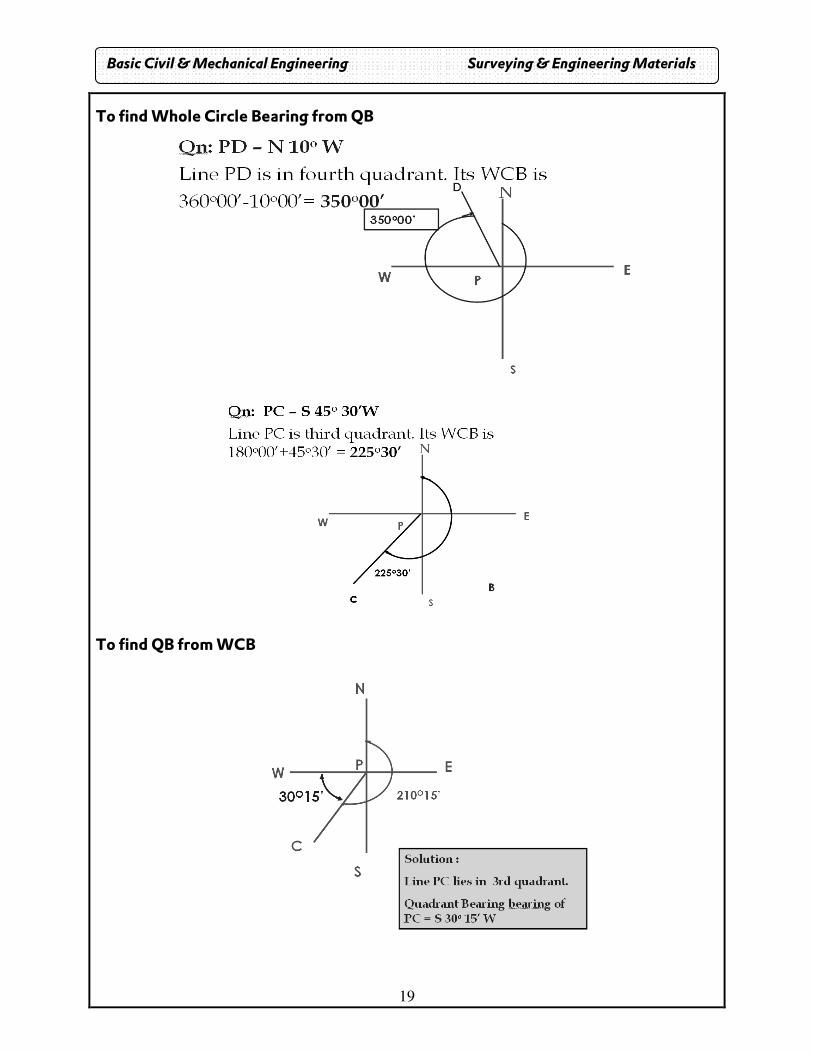
To find Whole Circle Bearing from QB
Qn: PA – N 15o E Ans: Line PA is in the first quadrant. Its WCB is 15o
To find Whole Circle Bearing from QB Qn: PB – S 25o 45’ E Line PB is in second quadrant. Its WCB is 180o00’-25o45’ = 154o15’
To find back bearing from Fore Bearing
N
E
S
W
15O
P
A
Basic Civil & Mechanical Engineering Surveying & Engineering Materials
19
To find Whole Circle Bearing from QB
To find QB from WCB
Basic Civil & Mechanical Engineering Surveying & Engineering Materials
20
1.7. LEVELLING Leveling is a branch of surveying the object of which is:
(1) To find the elevations of given points with respect to a given or assumed datum,
(2) To establish points at a given elevation or at different elevations with respect to
a given or assumed datum.
1.7.1. PRINCIPLES OF LEVELLING • The principles of level lies in furnishing a horizontal line of sight and find the
vertical distance of the points above or below the line of site.
• A line of sight is provided with a level, and a graduated leveling staff provides the
vertical height of a station with reference to the level line.
1.7.2. INSTRUMENTS USED FOR LEVELLING
The instrument commonly used in direct Levelling is:
(1) A level (2) A levelling staff.
1.7.2.1. LEVEL A Level consists of the following four parts:
1 A telescope to provide line of sight
1. A level tube to make the line of sight horizontal
2. A levelling head (tribrach and trivet stage) to bring the
3. Bubble in its centre of run
4. A tripod to support the instrument.
1.7.2.1.1. Types of levels
1. Dumpy level 2. Wye level 3.Reversible level 4.Tilting level
1. Dumpy level
1. The dumpy level consists of a telescope tube firmly secured in two collars fixed by
screws to the stage carried by the vertical spindle.
2. The modern form of dumpy level has the telescope tube and the vertical spindle
cast in one piece and a long bubble tube is attached to the top of the telescope. This
form is known as solid dumpy.
Basic Civil & Mechanical Engineering Surveying & Engineering Materials
21
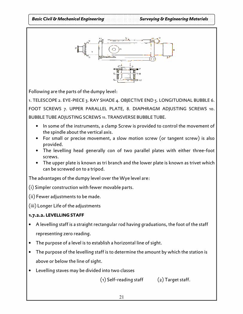
Following are the parts of the dumpy level:
1. TELESCOPE 2. EYE-PIECE 3. RAY SHADE 4. OBJECTIVE END 5. LONGITUDINAL BUBBLE 6.
FOOT SCREWS 7. UPPER PARALLEL PLATE, 8. DIAPHRAGM ADJUSTING SCREWS 10.
BUBBLE TUBE ADJUSTING SCREWS 11. TRANSVERSE BUBBLE TUBE.
• In some of the instruments, a clamp Screw is provided to control the movement of the spindle about the vertical axis.
• For small or precise movement, a slow motion screw (or tangent screw) is also provided.
• The levelling head generally con of two parallel plates with either three-foot screws.
• The upper plate is known as tri branch and the lower plate is known as trivet which can be screwed on to a tripod.
The advantages of the dumpy level over the Wye level are:
(i) Simpler construction with fewer movable parts.
(ii) Fewer adjustments to be made.
(iii) Longer Life of the adjustments
1.7.2.2. LEVELLING STAFF
• A levelling staff is a straight rectangular rod having graduations, the foot of the staff
representing zero reading.
• The purpose of a level is to establish a horizontal line of sight.
• The purpose of the levelling staff is to determine the amount by which the station is
above or below the line of sight.
• Levelling staves may be divided into two classes
(1) Self-reading staff (2) Target staff.
Basic Civil & Mechanical Engineering Surveying & Engineering Materials
22
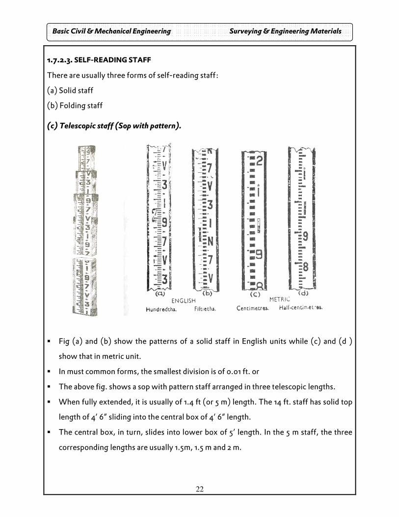
1.7.2.3. SELF-READING STAFF
There are usually three forms of self-reading staff:
(a) Solid staff
(b) Folding staff
(c) Telescopic staff (Sop with pattern).
� Fig (a) and (b) show the patterns of a solid staff in English units while (c) and (d )
show that in metric unit.
� In must common forms, the smallest division is of 0.01 ft. or
� The above fig. shows a sop with pattern staff arranged in three telescopic lengths.
� When fully extended, it is usually of 1.4 ft (or 5 m) length. The 14 ft. staff has solid top
length of 4’ 6” sliding into the central box of 4’ 6” length.
� The central box, in turn, slides into lower box of 5’ length. In the 5 m staff, the three
corresponding lengths are usually 1.5m, 1.5 m and 2 m.
Basic Civil & Mechanical Engineering Surveying & Engineering Materials
23
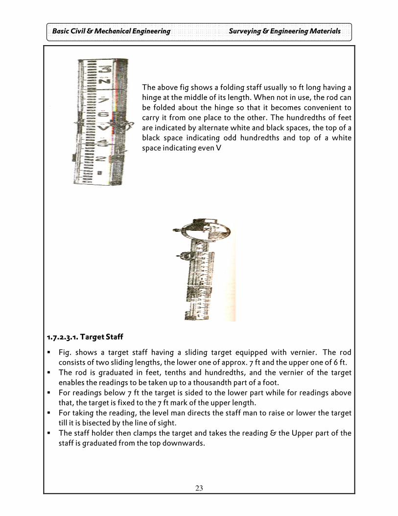
The above fig shows a folding staff usually 10 ft long having a hinge at the middle of its length. When not in use, the rod can be folded about the hinge so that it becomes convenient to carry it from one place to the other. The hundredths of feet are indicated by alternate white and black spaces, the top of a black space indicating odd hundredths and top of a white space indicating even V
1.7.2.3.1. Target Staff
� Fig. shows a target staff having a sliding target equipped with vernier. The rod consists of two sliding lengths, the lower one of approx. 7 ft and the upper one of 6 ft.
� The rod is graduated in feet, tenths and hundredths, and the vernier of the target enables the readings to be taken up to a thousandth part of a foot.
� For readings below 7 ft the target is sided to the lower part while for readings above that, the target is fixed to the 7 ft mark of the upper length.
� For taking the reading, the level man directs the staff man to raise or lower the target till it is bisected by the line of sight.
� The staff holder then clamps the target and takes the reading & the Upper part of the staff is graduated from the top downwards.
Basic Civil & Mechanical Engineering Surveying & Engineering Materials
24
CLASSIFICATION OF LEVELLING
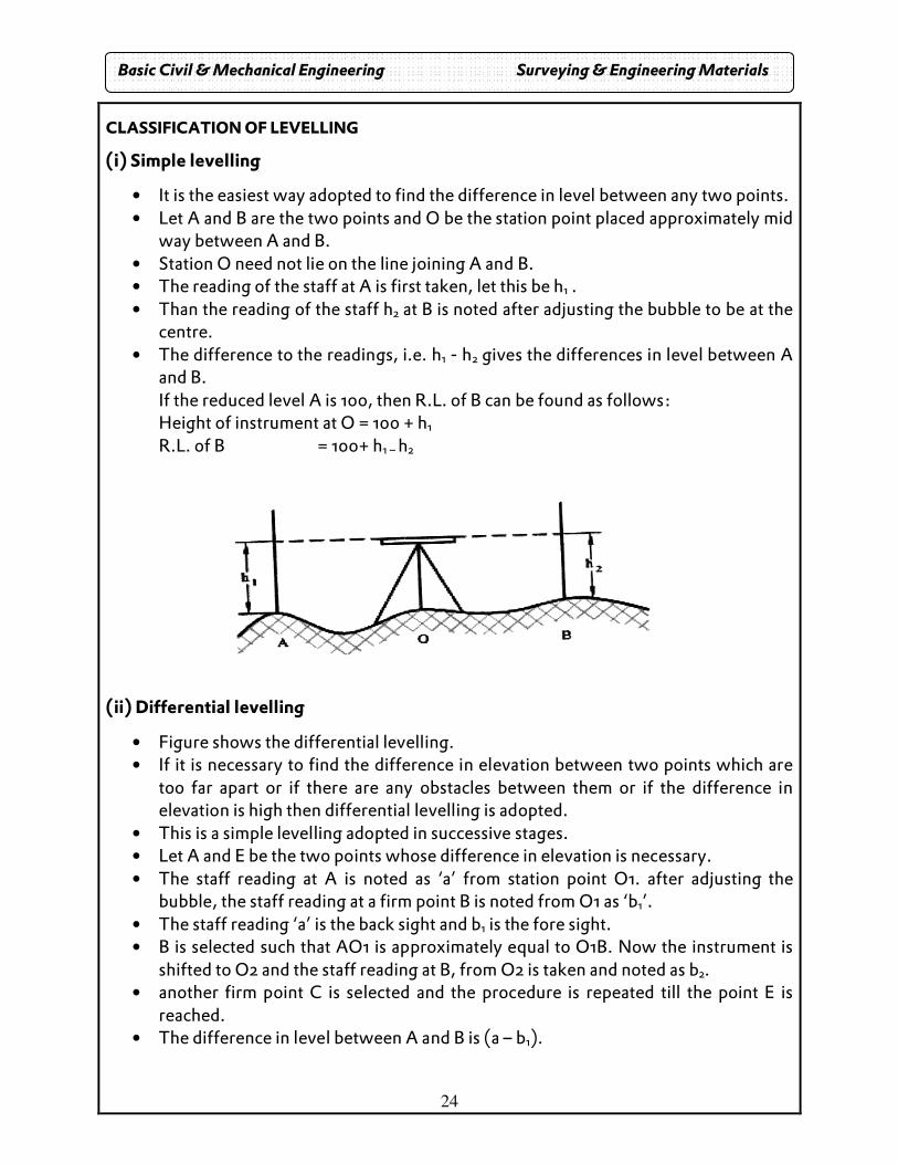
(i) Simple levelling
• It is the easiest way adopted to find the difference in level between any two points. • Let A and B are the two points and O be the station point placed approximately mid
way between A and B. • Station O need not lie on the line joining A and B. • The reading of the staff at A is first taken, let this be h1 . • Than the reading of the staff h2 at B is noted after adjusting the bubble to be at the
centre. • The difference to the readings, i.e. h1 - h2 gives the differences in level between A
and B. If the reduced level A is 100, then R.L. of B can be found as follows: Height of instrument at O = 100 + h1
R.L. of B = 100+ h1 – h2
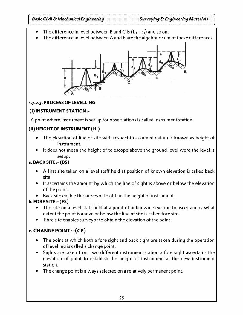
(ii) Differential levelling
• Figure shows the differential levelling. • If it is necessary to find the difference in elevation between two points which are
too far apart or if there are any obstacles between them or if the difference in elevation is high then differential levelling is adopted.
• This is a simple levelling adopted in successive stages. • Let A and E be the two points whose difference in elevation is necessary. • The staff reading at A is noted as ‘a’ from station point O1. after adjusting the
bubble, the staff reading at a firm point B is noted from O1 as ‘b1’. • The staff reading ‘a’ is the back sight and b1 is the fore sight. • B is selected such that AO1 is approximately equal to O1B. Now the instrument is
shifted to O2 and the staff reading at B, from O2 is taken and noted as b2. • another firm point C is selected and the procedure is repeated till the point E is
reached. • The difference in level between A and B is (a – b1).
Basic Civil & Mechanical Engineering Surveying & Engineering Materials
25
• The difference in level between B and C is (b2 – c1) and so on. • The difference in level between A and E are the algebraic sum of these differences.
1.7.2.3. PROCESS OF LEVELLING
(i) INSTRUMENT STATION:-
A point where instrument is set up for observations is called instrument station.
(ii) HEIGHT OF INSTRUMENT (HI)
• The elevation of line of site with respect to assumed datum is known as height of instrument.
• It does not mean the height of telescope above the ground level were the level is setup.
a. BACK SITE:- (BS)
• A first site taken on a level staff held at position of known elevation is called back site.
• It ascertains the amount by which the line of sight is above or below the elevation of the point.
• Back site enable the surveyor to obtain the height of instrument. b. FORE SITE:- (FS)
• The site on a level staff held at a point of unknown elevation to ascertain by what extent the point is above or below the line of site is called fore site.
• Fore site enables surveyor to obtain the elevation of the point.
c. CHANGE POINT: -(CP)
• The point at which both a fore sight and back sight are taken during the operation of levelling is called a change point.
• Sights are taken from two different instrument station a fore sight ascertains the elevation of point to establish the height of instrument at the new instrument station.
• The change point is always selected on a relatively permanent point.
Basic Civil & Mechanical Engineering Surveying & Engineering Materials
26
d. INTERMEDIATE SIGHT:- (IS)
• The F.S taken on a level staff held at points between two turning points to determine the elevation of points is known as intermediate sight.
• It may be noted that for one setting of the level there will be only a back sight and fore sight but there can be a number of intermediate sights.
1.7.2.4. ERRORS IN LEVELLING:-
Errors in leveling may be categorized into 1. Personal error 2. Errors due to natural factors 3. Instrumental error
1. PERSONAL ERROR:- Personal error include the following (i) Error in sighting:
• This is caused when it is difficult to see the exact coincide of the crosshairs and the staff graduation.
• This may be either due to long sights or due to poor focusing of the crosshair.
• Some times atmospheric air, atmospheric condition also cause on error in sighting.
• This error is accidental and may be classified as compensative.
(ii) Error in manipulation:-
• This is due to careless setting up of the level neither the telescope nor the tripod should be disturbed while taking readings.
• The instrument should be set up on a firm ground and carefully leveled. • Take care that the bubble is centre when the readings are observed. • If the bubble is not centered a Horizontal axis telescope gets inclined affecting the
staff readings. • The error is more for long sights & less for short sights. • To avoid the error the observer should develop the habit of checking the bubble
before and after taking reading.
(iii) Non Vertically of staff :
• If the staff is not held vertical during observation of the staff reading the observed value will be higher than the actual value.
• The staff should be held vertical using a plumb bob.
Basic Civil & Mechanical Engineering Surveying & Engineering Materials
27
2. Error is reading the staff:
These error generally committed are (i) Reading the staff up side down. (ii) Reading top or bottom hair instead of center hair. (iii) Concentrating the attention on decimal part of reading and entering the whole
value wrongly. (iv) Reading the inverted staff as a vertically held staff.
3. Error is recording & computation:- Common errors is recording are (i) Entering the reading in the wrong column that is B.S reading in the I.S or F.S column. (ii) recording the reading with digits inter change. (iii) Omitting on entry. (iv) Adding the F.S reading instead of subtracting with and subtracting a B.S reading instead of adding. Problem:
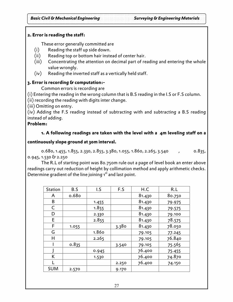
1. A following readings are taken with the level with a 4m leveling staff on a
continuously slope ground at 30m interval.
0.680, 1.455, 1.855, 2.330, 2.855, 3.380, 1.055, 1.860, 2.265, 3.540 , 0.835, 0.945, 1.530 & 2.250
The R.L of starting point was 80.750m rule out a page of level book an enter above readings carry out reduction of height by collimation method and apply arithmetic checks. Determine gradient of the line joining 1st and last point.
Station B.S I.S F.S H.C R.L
A 0.680 81.430 80.750 B 1.455 81.430 79.975 C 1.855 81.430 79.575 D 2.330 81.430 79.100 E 2.855 81.430 78.575 F 1.055 3.380 81.430 78.050 G 1.860 79.105 77.245 H 2.265 79.105 76.840 I 0.835 3.540 79.105 75.565 J 0.945 76.400 75.455 K 1.530 76.400 74.870 L 2.250 76.400 74.150
SUM 2.570 9.170
Basic Civil & Mechanical Engineering Surveying & Engineering Materials
28
Arithmetic check
∑ BS - ∑ FS = RL of last point – RL of first point
2.570 – 9.170 = 74.150 – 80.750 = - 6.600
Gradient is 6.600m in 360m
∴∴∴∴ slope = 1 in 54.54
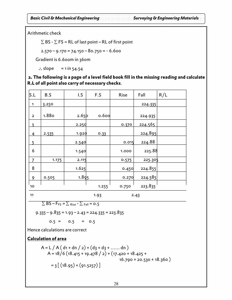
2. The following is a page of a level field book fill in the missing reading and calculate R.L of all point also carry of necessary checks. S.L B.S I.S F.S Rise Fall R/L
1 3.250 224.335 2 1.880 2.650 0.600 224.935
3 2.250 0.370 224.565
4 2.535 1.920 0.33 224.895
5 2.540 0.015 224.88
6 1.540 1.000 225.88
7 1.175 2.115 0.575 225.305
8 1.625 0.450 224.855
9 0.505 1.895 0.270 224.585
10 1.255 0.750 223.835
11 1.93 2.43
∑ BS – FFS = ∑ Rise - ∑ Fall = 0.5
9.335 – 9.835 = 1.93 – 2.43 = 224.335 = 223.835
0.5 = 0.5 = 0.5
Hence calculations are correct
Calculation of area
A = L / A ( d1 + dn / 2) + (d3 + d3 + …… dn ) A = 18/6 (18.415 + 19.478 / 2) + (17.420 + 18.425 +
16.790 + 20.530 + 18.360 ) = 3 [ (18.95) + (91.5257) ]
Basic Civil & Mechanical Engineering Surveying & Engineering Materials
29
= 331.46 m²
(or) A = L’ /3 [ (∑ (end co-ordinates ) + 4 (sum of even ordinate) + 2 (sum of add ordinate) ] A = 3/3 [18.415 + 19.478] + 4 [17.720 + 16.790 + 18.360] + 2 [18.425 + 20.530]
� 37.893 + 4 [52.87] + 2 [38.96] + 211.48 + 77.91 � 327.3 m²
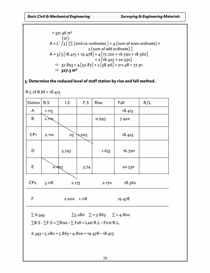
3. Determine the reduced level of staff station by rise and fall method. R.L of B.M = 18.415 Station B.S I.S F.S Rise Fall R/L
A 1.115 18.415
B 2.110 0.995 7.420
CP1 2.110 05 1.005 18.425
D 3.745 1.635 16.790
E 0.005 3.74 20.530
CP2 3.118 2.175 2.170 18.360
F 2.000 1.118 19.478
∑ 6.343 ∑5.280 ∑ = 5.863 ∑ = 4.800
∑B.S - ∑F.S = ∑Rise – ∑ Fall = Last R.L – First R.L. 6.343 – 5.280 = 5.863 – 4.800 = 19.478 – 18.415
Basic Civil & Mechanical Engineering Surveying & Engineering Materials
30
Chapter – II : BRICKS 1.8. General:
• Bricks are the most commonly used building material. • It is made from soil generally clay. • The clay is moulded to form rectangular blocks of standard size, which are
dried and then burnt at a high temperature. • This makes a dense and compact material called brick. • Easy availability, good strength, durability and insulating and fire resisting
properties of good bricks made them as the most essential building material.
1.9. COMPOSITION: (a) alumina (b) oxide of iron (c) silica (d) magnesia (e) lime
Alumina: A good brick contains about 20% to 30% alumina. Silica: A good brick contains about 50% to 60% of silica. It prevents cracking. Lime: A small quantity of lime not exceeding 5% is desirable. It prevents shrinkage. Oxide of iron: A small quantity of oxide 5% to 6% is desirable. It also imports red color.
Harmful ingredients:
Lime & alkalis:
The excess of lime and alkalis causes the brick to melt and lost its shape. Iron pyrites:
If iron pyrites are present in brick they are disintegrated during burning.
Organic matter:
This organic matter in brick earth assists in burning. But if such matter is not completely burnt the bricks become porous.
Basic Civil & Mechanical Engineering Surveying & Engineering Materials
31
1.10. QUALITIES OF GOOD BRICK:
� It should be table moulded. � It should have uniform color � It should be free from cracks � It should have low thermal conductivity � It should not break on hard ground when dropped from a height of 1m. � It should have min strength of 3.5N/mm2 .
1.11. CLASSIFICATION: � unburnt or sun dried bricks � burnt bricks
a. Unburnt bricks: They are dried with the help of heat received from the sun after the process of moulding. b. Burnt bricks: They are classified into four categories:
1. First Class 2. Second class 3. Third class 4. Fourth class.
1. First class:
• These are well burnt and regular size and shape. • The minimum crushing strength will be 10.5N/mm2. • it is used for superior works.
2. Second class: • Used at places where brick work is to be provided with coat of plaster. • The surfaces of the bricks are rough and slightly irregular in shape. • The minimum crushing strength will be 7 N/mm2.
3. Third class:
• The bricks are ground moulded. • These bricks are not hard but rough with irregular and distorted edges. • These give a dull sound when struck with each other. • These bricks are used for temporary works and at places where rainfall is not
heavy. • The minimum crushing strength will be 3.5N/mm2.
Basic Civil & Mechanical Engineering Surveying & Engineering Materials
32
4. Fourth class:
• This bricks are over burnt bricks. • With irregular shape and dark colour. • They used as aggregates for concrete in foundations, floors.
Uses:
I. It is used for construction of walls. II. It is used as refractory material
III. It is used in construction of chimney IV. Bricks with cavities are known as hollow bricks used for front wall
structures V. Sand-line bricks used for ornamental works
1.12. MOULDING OF BRICKS:
1.12.1. Hand moulding: • It is done by rectangular box with open at top and bottom. • it may be wood or steel.
1.12.2. Types: a. Ground moulding: b. Table moulding
a. GROUND MOULDING:
• First small portion of ground is cleared and leveled. • Fine sand is sprinkled over it. • Moulding is dipped in water and kept on ground and clay is pressed by hand
so that all corners are filled with clay sand excess is scraped by strikes. • Process is repeated fill the ground is covered with bricks. • After that bricks become dry, it is sent for next of drying.
b. TABLE MOULDING:
Instead of ground in table the table used is the size of 2mx1m.
• When bricks are manufactured in huge quantity these are done by machines.
• The machine containing the rectangular opening under pressure, it is cut into strips by wire fixed in frames.
ii. DRYING OF BRICKS:
• This is done in drying yards. • Bricks are stacked in 8 to 10 bricks in each row and they are dried for 5 to 12 days
Basic Civil & Mechanical Engineering Surveying & Engineering Materials
33
iii. BURNING: • It imports hardness and strength of bricks. • It must be done carefully because unburnt bricks remains soft and over burnt bricks
become brittle and hence break easily. • It is done in kilns.
Characteristics of good bricks
Shape and size: Bricks should be truly rectangular in shape with sharp edges and plane faces. The size of the bricks should comply with that specified for the purpose.
Physical proprieties: Good bricks should be hard, sound and well burnt and should give a metallic sound when struck with another brick or with hammer. They should have uniform colour and fine compact texture. When brick is dropped down from a height of one meter on another brick, it should not break. This bricks should be free from fissures, cracks, pebbles, nodules of free lime, etc.
Compressive strength: Good bricks should have high compressive strength for better durability. Building bricks have a compressive strength of about 5 to 40N/mm2 when tested on flat position depending upon their type and quality.
Flexural strength: This is the resistance of bricks to bending. The flexural strength of building bricks varies from 7 to 20 N/mm2 depending upon their type and quality.
Water absorption: This is determined by knowing the quantity of water absorbed by a brick when immersed in water under standard conditions. The brick should not absorb water more than 20% of its own weight.
Presence of soluble salts: The salts like sulphates of calcium, magnesium, sodium and potassium present in bricks cause efflorescence on the surface of masonry when they get dissolved in water. The water allowable percentage of soluble salts in bricks is 0.5 to 2.5. If they are present in large quantities, they keep the masonry permanently in a damp condition and cause decay in bricks due to crystallization. Thus, bricks containing a higher percentage of soluble salts have resistance to weathering.
Resistance to weathering: Bricks should have high resistance to frost action. The unburnt constituents of clay, if present in bricks, chemically combine with water to bring about decay in the bricks. As said earlier, the presence of soluble salts in excess quantity makes the bricks less resistant to weathering.
Thermal conductivity and sound insulation: Good building bricks have low thermal conductivity and high sound insulation properties. Light weight and hollow blocks have better sound insulation and low thermal conductivity.
Basic Civil & Mechanical Engineering Surveying & Engineering Materials
34
Fire resistance of bricks: The bricks possess very high resistance to fire. They are non-combustible and non-inflammable.
Expansion of bricks: The bricks should not undergo a large change in volume on wetting. An excessive volume change on wetting indicates the under-burnt nature of bricks.
Uses of bricks
• Bricks are used for the construction of walls in houses and other structures.
• Bricks are used in the construction of bridges and dams.
• Bricks are used in the construction of kerbs, islands, etc. in roads. In all the above ,
first class bricks are used for superior works, second class bricks for ordinary
works, third class bricks for unimportant works.
• Bricks are used for paving. Such bricks are called paving bricks.
• Perforated and hallow bricks are used for heat insulation purposes.
• Pressed bricks are used for decorative works and very high quality works.
• Fire bricks are used for lining the interiors of furnaces, flues, ovens, chimneys,
boilers and other fire places subjected to the action of high heat and fire.
Basic Civil & Mechanical Engineering Surveying & Engineering Materials
35
Chapter – III STONES
General
• Stones are naturally available building materials. • They are obtained from occurring rocks. • The properties of stones normally depend on the type of rock from which they are
formed.
1.13. Classifications: � Geological � Physical � Chemical
a. Geological: i. Igneous rock: The rocks which are formed by cooling of magma are known as igneous rocks which are inside earth’s surface. ii. Sedimentary rocks:
• They are formed by deposition of products of weathering on the pre existing rocks. • These products due to wind, rain, frost etc... • E.g.: limestone, gypsum.
iii. Metamorphic: When the preexisting rocks are subjected to great heat and pressure they are changed in character and forms metamorphic rocks. E.g.: marble b. Physical:
� Stratified rocks � Unstratified rocks � Foliated
i. Stratified: These rocks possess planes of stratification or cleavage and such rocks can be easily being split up along these planes.
ii. Unstratified: These rocks do not have any definite planes.
Basic Civil & Mechanical Engineering Surveying & Engineering Materials
36
iii. Foliated: These rocks have a tendency to be split up into definite direction only. c. Chemical classifications:
� Siliceous � Argillaceous � Calcareous
I. Siliceous: In these silica predominates. It is hard and durable.
ii. Argillaceous: In these clay predominates. These are hard and durable.
iii. Calcareous in this calcium predominates. The durability depends upon the constitutes present. 1.13.1. Qualities of good building stone:
� It should be homogeneous in structure. � It should be free from cracks. � It should be easily workable. � It must be fire resistant. � It should be easily obtainable.
1.13.2. Quarrying:
� By hand tool � By blasting
a. By hand tools: They are executed by pick-axes hammer, chisels, etc.. b. By blasting: In this process explosives are used. c. Uses:
o Stones are used for pavements o Used for foundations o Ballast in railways o Used for bridges, dams, etc…
Basic Civil & Mechanical Engineering Surveying & Engineering Materials
37
1.13.3. A GOOD BUILDING STONE SHOULD HAVE THE FOLLOWING QUALITIES:
a. Appearance:
• For face work it should have fine, compact texture. • Light colored stone is preferred as it is more durable.
b. Structure:
• A broken stone should not be dull in appearance and should have uniform texture free from cavities, cracks and patches of loose or soft material.
• Stratifications should not be visible to naked eye.
c. Strength: • A stone should be strong and durable to withstand the disintegrating action
of weather. • Compressive strength of building stones in practice range between 60 to
200 N/mm2. d. Weight:
• It is an indication of the porosity and density. • For stability of structures such as dams, retaining walls etc. • heavier stones are required, whereas for arches, vaults, domes etc. • light stones are used.
e. Hardness:
• This property is important for floors, pavements, aprons of bridges; etc. • The hardness is determined by the Mohr’s scale.
f. Toughness:
• The measure of impact that a stone can withstand is defined as toughness. • The stone used should be tough when vibratory or moving loads are
anticipated. g. Porosity and absorption:
• Porosity depends on the mineral constituents, cooling time and structural formation.
• A porous stone disintegrates as the absorbed rain water freezes, expands and causes cracking.
• Permissible water absorption for some of the stoners is given in table. h. Seasoning: The stone should be will seasoned.
Basic Civil & Mechanical Engineering Surveying & Engineering Materials
38
i. Weathering:
The resistance of stone against the wear and tear due to natural agencies should be high.
j. Workability:
Stone should be workable so that cutting, dressing and bringing it out in the required shape and size may not be uneconomical.
k. Fire resistance:
• Stones should be free from calcium carbonate, oxides of iron, and minerals having different coefficients of thermal expansion.
• Limestone, however can withstand a little higher temperature ie Up to 8000C after which they disintegrate.
l. Specific Gravity: The specific Gravity of most of the stones lies between 2.3 to 2.5
m. Thermal Movement:
• Thermal movements alone are usually not trouble some. However joints in coping and parapets open out inletting the rain water causing trouble.
• An exposure of one side of marble slab to heat may cause that side to expand and the slab warps.
• On cooling the slab does not go back to its original shape
Basic Civil & Mechanical Engineering Surveying & Engineering Materials
39
Chapter – IV SANDS
General:
• Stones are naturally available building materials. • They are obtained from occurring rocks. • The properties of stones normally depend on the type of rock from which they are
formed • Sand is formed by the decomposition of sand stones due to various effects of
weather.
1.14. Functions of sand: The sand is used in the concrete for the following purpose:
a. Bulk: It does not increase the strength of the mortar but if bulk is increased the cost is reduced.
b. Shrinkage: It prevents excessive shrinkage during drying
c. Strength: It helps in the adjustment of strength by variation of its ratio with cement.
d. Surface area: It sub divides the paste of binding material and increase the surface area.
e. Classifications: � Pit sand � River sand � Sea sand
i. Pit sand: • It is excavated from the depth of about 1m to 2m. • It consists of sharp angular grains which are free from salts.
ii. River sand:
• It is obtained from bank of bed of river. • It consist of fine rounded grain and available in clean condition.
iii. Sea sand:
• It is obtained from sea shores. • It consists of fire rounded grains and contains salt. • These salts attract moisture from the Atmosphere and not used for
engineering purpose.
Basic Civil & Mechanical Engineering Surveying & Engineering Materials
40
Classification:
� Fine sand � Coarse sand � Gravelly
i. Fine sand: The sand passing through a screen with clear opening 1.5875mm and used for plastering.
ii. Coarse sand: This sand passing through a screen with clear with clear openings 3.175mm and used for masonry. iii. Gravelly sand: This sand passing through a screen with clear openings as 7.62mm and used for concrete work. 1.14.1. BULKING OF SAND: The presence of moisture in sand increases the volume of sand and it is known as bulking of sand.
1.14.2. PROPERTIES:
1. It should be chemically inert 2. It should be clean. 3. It should not contain salts. 4. It should be well graded.
1.14.3. TESTS: CLAY:
1. Specific Gravity test: A glass of water is taken out and sand is placed. It is vigorously shaken and allowed to settle. If clay is present its layer is formed on top of sand.
2. The color of sand will indicate the purity. 3. Add sodium hydroxide to sand and stride. If the color of solution changes to brown and it indicates the presence of organic matter.
Basic Civil & Mechanical Engineering Surveying & Engineering Materials
41
Chapter – V CEMENT
General:
• Cement is the product obtained by burning a well – proportioned mixture of calcareous material, such as lime stone, and argillaceous material, such as clay, at very high temperature.
• It has adhesive and cohesive properties. • It is a binding material used with stones, sand, bricks, building blocks etc. • the cement – water paste can bond well with aggregates to form a strong rock –
like mass called concrete. • The basic of cement and water after setting looks in colour and hardness like a
variety of stone found in Portland in England which is therefore called as “Portland cement”.
1.15. Constituents:
1. Argillaceous 2. Calcareous
In argillaceous clay is the main ingredient and un calcareous calcium carbonate is
the main ingredient. 1.15.1. Setting Action:
• When water is added to cement, the ingredients of cement react chemically with water and forms various complicated chemical compounds which import strength to cement.
• This phenomenon is called as hardening. 1.15.2. Manufacturing of cement:
1. Mixing of raw materials 2. Burning 3. Grinding
1.15.3. Mixing of raw materials: There are two methods,
1. Dry process 2. wet process
Basic Civil & Mechanical Engineering Surveying & Engineering Materials
42
Basic Civil & Mechanical Engineering Surveying & Engineering Materials
43
Basic Civil & Mechanical Engineering Surveying & Engineering Materials
44
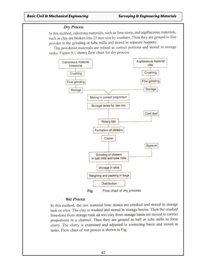
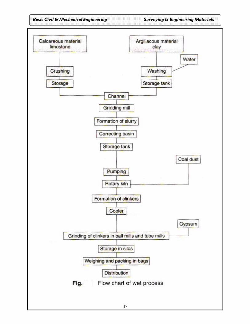
1. Dry process:
� In this limestone and clay are separately reduced to 25mm in crushers.
� After drying these materials are grinded in ball mills. � Then they are mixed in correct proportions and these materials are
stored in storage tank. 2. Wet process:
• In wet process limestone is crushed and stored in storage tanks. Clay is washed and stored in barrios.
• They are mixed and grinded in ball mill to form slurry and stored in storage tank.
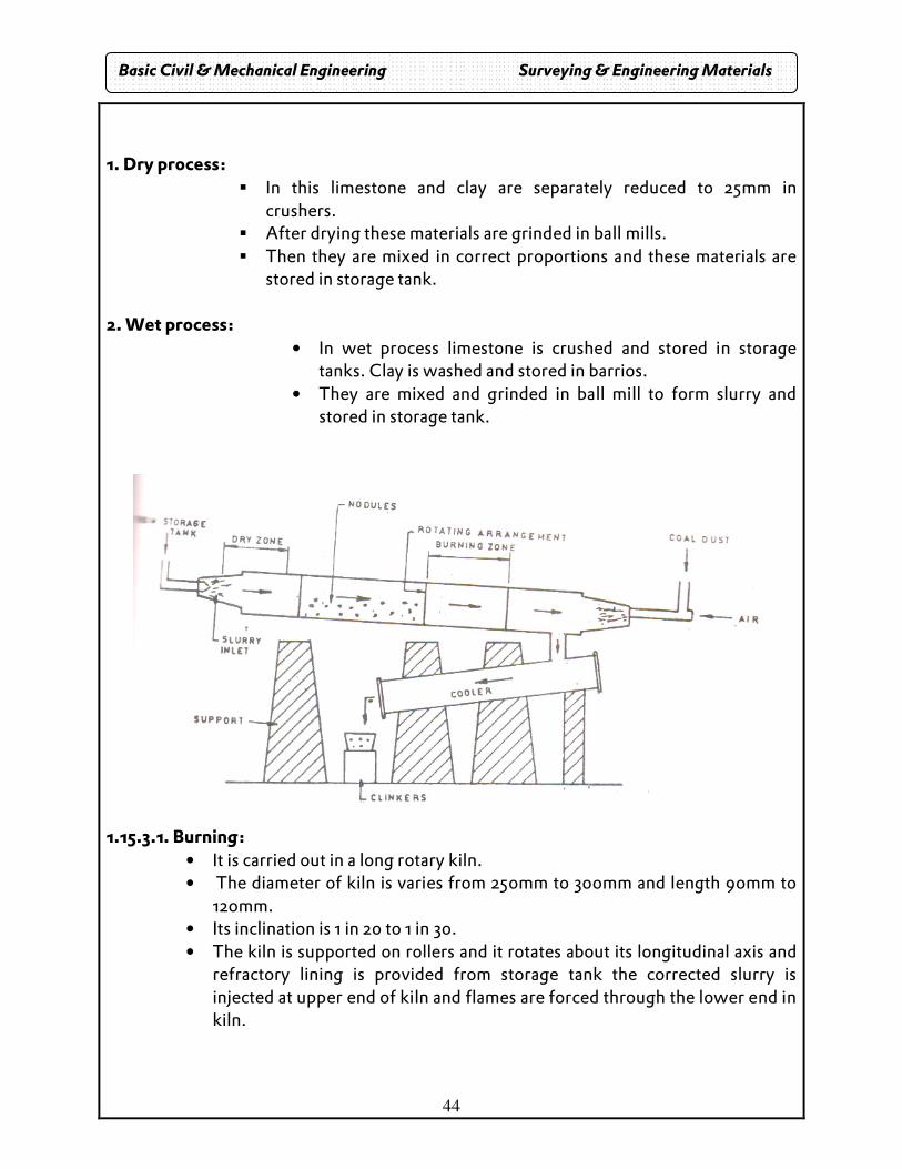
1.15.3.1. Burning:
• It is carried out in a long rotary kiln. • The diameter of kiln is varies from 250mm to 300mm and length 90mm to
120mm. • Its inclination is 1 in 20 to 1 in 30. • The kiln is supported on rollers and it rotates about its longitudinal axis and
refractory lining is provided from storage tank the corrected slurry is injected at upper end of kiln and flames are forced through the lower end in kiln.
Basic Civil & Mechanical Engineering Surveying & Engineering Materials
45
• The portion of kiln near upper end is known as dry zone and water from slurry is evaporated.
• As the dried slurry descends towards the burning zone. • Co2 is evaporated and it is converted into small lumps. • Then it reaches the burning zone (1500o C to 1700 o C) and lime and clay are
fused to form hard bulk of Portland cement known as clinkers. • The size of clinkers varies from 5mm to 10mm. • When the clinkers are cooled in the coolers.
1.15.3.2. Grinding:
• It is done in ball mills. • Here gypsum is added to control the initial setting. • If gypsum is not added it would set as soon as water is added. • Then it is stored, weighted and packed in bags, each bag of cement contains
50kg of cement. (or 0.035m3 Volume of cement). 1.15.3.3. PROPERTIES:
1. The color should be in uniform. 2. Free from lumps. 3. Weight of magnesia not exceeds 5%. 4. Weight of sulphur not exceeds 2.75%. 5. If small quantity of cement is thrown into bucket of water, it should sink. 6. It gives strength to the masonry 7. It gives an excellent binding material 8. It is easily workable 9. It posses a good plasticity. 10. the compressive strength of mortar in 1:3 mix after 7 days should not be
less than 22 N/mm2 and 33 N/mm2 after 28 days. 11. Final Setting time should not more than 10 hrs, and initial setting time
should not be less than 30 min.
1.15.4. TYPES: 1. Quick setting cement:
• It is produced by adding small percent of aluminum sulphate and cement. • The setting action starts within few minutes after addition of water. • USE: to lay concrete under water.
2. Expanding cement: The cement expands during by the addition of sulpho-aluminate.
USE: for repairing concrete surfaces.
Basic Civil & Mechanical Engineering Surveying & Engineering Materials
46
3. Rapid hardening: High strength is obtained by adding in gradients at high temperature and increasing
lime content. USE: speedy construction work.
4. White cement: It is white in color and it is free from coloring ingredients such as iron oxide,
manganese oxide etc. USE: used for floor furnish and plaster works and plaster works, aerodrome
marketing.
5. Coloring cement: It is obtained by mixing suitable materials chromium oxide-green cobalt-blue iron
oxide- brown color. USE: manufacturing of files, swimming pools, tennis courts.
6. Hydrophobic Cement:
• This type of cement contains admixtures which decrease the wetting ability of cement grains.
• The usual hydrophobic admixtures are acid, napthene soap, oxidized petroleum etc.
• When water is added to hydrophobic cement, the absorption films are turn off the surface and they do not in any way, prevent the normal hardening of cement.
• However, in initial stage, the gain in strength is less as hydrophobic films on cement grains prevent the interaction with water.
• When hydrophobic cement is used, the fine pores in concrete are uniformly distributed and thus the frost resistance and the water resistance of such concrete are considerably increased.
7. Low heat cement:
• The considerable heat is produced during the setting action of cement. • In order to reduce the amount of heat this type of cement is used. • It contains lower percentage of di-calcium silicate C2 S of about 46 %
8. Pozzolana Cement:
• The pozzolana is a volcanic powder. • It is found in Italy near Vesuvius. • It resembles surkhi which is prepared by burning bricks made form ordinary
soils. • The percentage of pozzolana material should be between 10 – 30.
Basic Civil & Mechanical Engineering Surveying & Engineering Materials
47
9. Quick setting cement:
• This cement is produced by adding a small percentage of aluminum sulphate and by finely grinding the cement.
• The percentage of gypsum or retarded setting action is also greatly reduced. • The addition of aluminum sulphate and fineness of grinding are responsible
for acceleration the setting action of cement the setting action of cement starts within five minutes after addition of water and it becomes hard like stone in less than 30 minutes or so.
10. Rapid hardening cement:
• The initial and final setting times of this cement are the same as those of ordinary cement. But it attains high strength in early days.
• It contains high percentage of tribalism silicate C3 S to the extent of about 56%.
10. Sulphate resisting cement:
• In this cement, the percentage of tricalcium aluminate C3 A is kept below 5% and it results in the increase in resisting power against sulphates.
• This cement is used for structures which are likely to be damaged by severe alkaline conditions such as canal linings, Culverts, siphons etc.
1.15.5. Physical tests available for cement
Fineness:
The degree of fineness of cement is the measure of the mean size of the grain it. There are three methods for testing fineness. a. Sieve Method b. Air permeability test c. Sedimentation Method.
Basic Civil & Mechanical Engineering Surveying & Engineering Materials
48
Chapter – VI CONCRETE
General: • Concrete is a mixture of cement, fine aggregate(sand), coarse aggregate and water
in suitable proportion.
• The mix is then placed in moulds or forms and a plastic mass is formed.
• The plastic mass is cured and it becomes hard solid mass called Concrete.
• The chemical reaction between the cement and water, known as hydration of
cement, causes the hardening.
• The cement and water form a paste, which upon hardening binds the aggregates to
a permanent mass called concrete.
• The mortar used in concrete called matrix.
• The cement is called binding material.
1.16. Constituents:
Cement: Selection of particular type depends on specific conditions. Aggregates: Coarse aggregates: Aggregates pass through 20mm mesh. E.g.: Stone, broken brick.
Fine aggregates: Aggregates pass through 4.75mm mesh. E.g.: Sand.
Water: Purpose of water:
1. To form the paste. 2. Enables the concrete mix to flow into moulds.
1.16.1. Workability: Workability is defined as the ease with which it can be mixed, transported and placed. Wet concrete more workable than dry concrete. 1.16.2. Batching: The measurement of materials for making concrete is known as Batching. Weight Batch -> cement. Weight Batch -> aggregates.
Basic Civil & Mechanical Engineering Surveying & Engineering Materials
49
1.16.3. MIXING: Mass becomes homogeneous and uniform. There are two types
1. Hand mixing. 2. Machine mixing.
a. Transporting: Mortar pan, bucket and rope Belt conveyors are used. b. Placing:
It should be placed in systematic manner to yield maximum result.
c. Compacting: It should be compared to eliminate air bubbles and obtain maximum density.
d. Curing: It should be wet at least for 7 days to promote continued hydration.
e. PURPOSE: 1. Increases durability. 2. Reduces shrinkage. 3. Increases wear resistance.
1.16.4. Types: a. Plain Cement Concrete: It is mixture of cement, sand, crushed rock and water.
1. Free from corrosion. 2. High compressive strength. 3. It binds rapidly with steel.
b. R.C.C: Plains concrete strong in compression but weak in tension. To increase the tensile strength steel bars are embedded in concrete known as R.C.C. c. Pre Stressed Concrete: Here high tensile steel wires are used instead of mild steel bars. There are two types:
1. Pre tensioning 2. Post tensioning.
Basic Civil & Mechanical Engineering Surveying & Engineering Materials
50
1. Pre Tensioning: � The wires are initially stressed and concrete is cost.
2. Post tensioning:
� The wires are placing inside the concrete and then stressed. It saves the concrete and steel 50 to 80% compared with R.C.C.
d. Pre-cast concrete:
� It is manufactured in factory and transmitted to site. Advantages:
1. They are finished with accuracy. 2. High quality. 3. It is completed in short time. 4. It can be dismantled when required and they are suitable used else
where. Ordinary port land cement: Most common cement used in mortar and concrete Use: multistoried residential building, clams, bridges slaps, poles, pipes High density concrete: High density concrete is prepared by adding high density materials like steel shot, iron shot, lead shot, and barites along with regular aggregates. High density concrete is used for shield walls in nuclear power plants, sea walls and other similar structures that require to be highly dense. Polymer concrete: Polymer concrete is produced by adding monomers along with regular aggregates. These monomers are polymerized subsequently. Polymers are compounds whose molecules are formed by combining a large number of simple molecules. Polymer concrete is used for wall facing and curtain walls. Fibre reinforced concrete: Fibre reinforced concrete is prepared by adding fibers of glass, carbon, nylon and similar materials. The length, diameter and quantity of fibers added to the concrete may vary depending upon the use and desired strength. Fibre reinforced concrete is used in places where higher strength and impact resistance are called for. Prestressed concrete: Cement concrete introduced with prestressed steel bars of high tensile strength is called prestressed concrete. The steel bars may be pre-tensioned or post-tensioned.
Basic Civil & Mechanical Engineering Surveying & Engineering Materials
51
1.16.5. Factors that affect workability of concrete
a) Water content b) Micro proportions c) Size of aggregates d) Shape of aggregates e) Surface textures of aggregate
1.16.7. Explain the slump test
• Slump test is the most commonly used method of measuring consistency of concrete.
• It can be employed either in laboratory or at work site. • It is not a suitable method for very wet or very dry concrete. • However, it can be used to check quality of concrete and gives an indication of the
uniformity of concrete from batch to batch. • Additional information on workability and quality of concrete can be obtained by
observing the manner in which concrete slumps. • Quality of concrete can also be further assessed by giving a blows with tamping rod
to the base plate and observing the flow. • The apparatus far conducting the slump test, essentially consists of a metallic in the
form of a function of a cone having the internal dimensions as under: • Bottom diameter : 20cm • Top diameter : 10cm and Height : 30cm
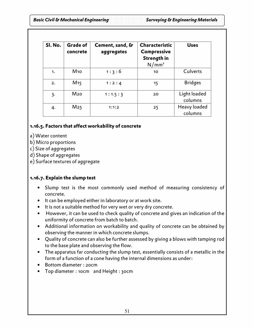
Sl. No. Grade of concrete
Cement, sand, & aggregates
Characteristic Compressive Strength in
N/mm2
Uses
1. M10 1 : 3 : 6 10 Culverts
2. M15 1 : 2 : 4 15 Bridges
3. M20 1 : 1.5 : 3 20 Light loaded columns
4. M25 1:1:2 25 Heavy loaded columns
Basic Civil & Mechanical Engineering Surveying & Engineering Materials
52
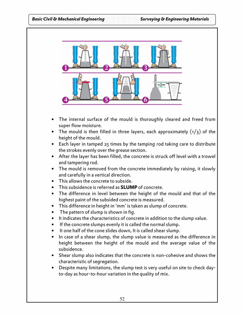
• The internal surface of the mould is thoroughly cleared and freed from
super flow moisture. • The mould is then filled in three layers, each approximately (1/3) of the
height of the mould. • Each layer in tamped 25 times by the tamping rod taking care to distribute
the strokes evenly over the grease section. • After the layer has been filled, the concrete is struck off level with a trowel
and tampering rod. • The mould is removed from the concrete immediately by raising, it slowly
and carefully in a vertical direction. • This allows the concrete to subside. • This subsidence is referred as SLUMP of concrete. • The difference in level between the height of the mould and that of the
highest paint of the subsided concrete is measured. • This difference in height in ‘mm’ is taken as slump of concrete. • The pattern of slump is shown in fig. • It indicates the characteristics of concrete in addition to the slump value. • If the concrete slumps evenly it is called the normal slump. • It one half of the cone slides down, It is called shear slump. • In case of a shear slump, the slump value is measured as the difference in
height between the height of the mould and the average value of the subsidence.
• Shear slump also indicates that the concrete is non-cohesive and shows the characteristic of segregation.
• Despite many limitations, the slump test is very useful on site to check day-to-day as hour-to-hour variation in the quality of mix.
Basic Civil & Mechanical Engineering Surveying & Engineering Materials
53
• The slump test gives warning to correct the causes for change of slump value.
• Due to simplicity of the test it is popularly used to find workability of fresh concrete in spite if that many workability tests are in vogue.
1.16.8. Bulking of sand
• Increase in volume of sand due to moisture content is called bulking. • Sand volume increases by 20% at a moisture content of 4% when compared
to dry sand. • Due to bulking of sand suitable correction in quantity of sand should be
made during volume batching of concrete.
Properties
1. Concrete has high compressive strength and low tensile strength. For M 15 concrete, the characteristic compressive strength is 15N/mm2 and permissible tensile strength 2N/mm2
2. Richer mixes increase the strength of concrete.
3. The strength of concrete increases with age. For all practical purposes, the concrete is deemed to have attained its full strength in one month’s time
4. Good hardened concrete is dense, the density being2410kg/m3.
5. The water –cement ratio of good workable concrete is 0.5to0.6. With the use of vibrators, this value can be reduced and greater strength attained.
6. Concrete shrinks while hardening. The shrinkage strain of concrete is approximately 0. 0003.
7. The modulus of elasticity of concrete is 14kN/mm2 or 14 GN/m2.
Uses of cement concrete
1. Cement concrete is used for many types of building works. beams, lintels, staircases, bridges, silos, etc, are cast using cement concrete with steel reinforcement. 2. Concrete is used for columns, water tank and front facing of dams. 3. it is used for piles in foundation and heavily loaded columns. 4. Lean mix of cement concrete is used for the rear portion of dams and general mass concreting in foundations, retaining walls, bridge piers, culverts, etc 5. It is also used in the fabrication of precast railway sleepers and piles.
54
Chapter VII STEEL
1.17. Introduction
• Generally steel is suitable for all constructional purposes. • The steel is the composition of iron and carbon based on the carbon content
it is classified into three types. (i) Wrought iron: carbon content upto 0.15% (ii) Steel: carbon content from 0.25 % to 1.5% (iii) Cast iron: carbon content from 2% to 4 %
Wrought iron is of fibers nature and it is suitable to resist tensile stresses. Steel is strong in compression as well as in tension. Cast iron is granular and can take only compressive stresses.
1.17.1. Manufacture of steel � Bessemer process � Cementation process � Duplex process � Open hearth process
1.17.2. Properties of steel 1. It can be readily forged 2. It can be magnetized permanently 3. It is not easily attacked by salt water 4. It rusts easily and rapidly 5. Melting point of mild steel is 400˚C 6. Hard steel melting point is 1300˚C
1.17.3. Market forms are available in steel
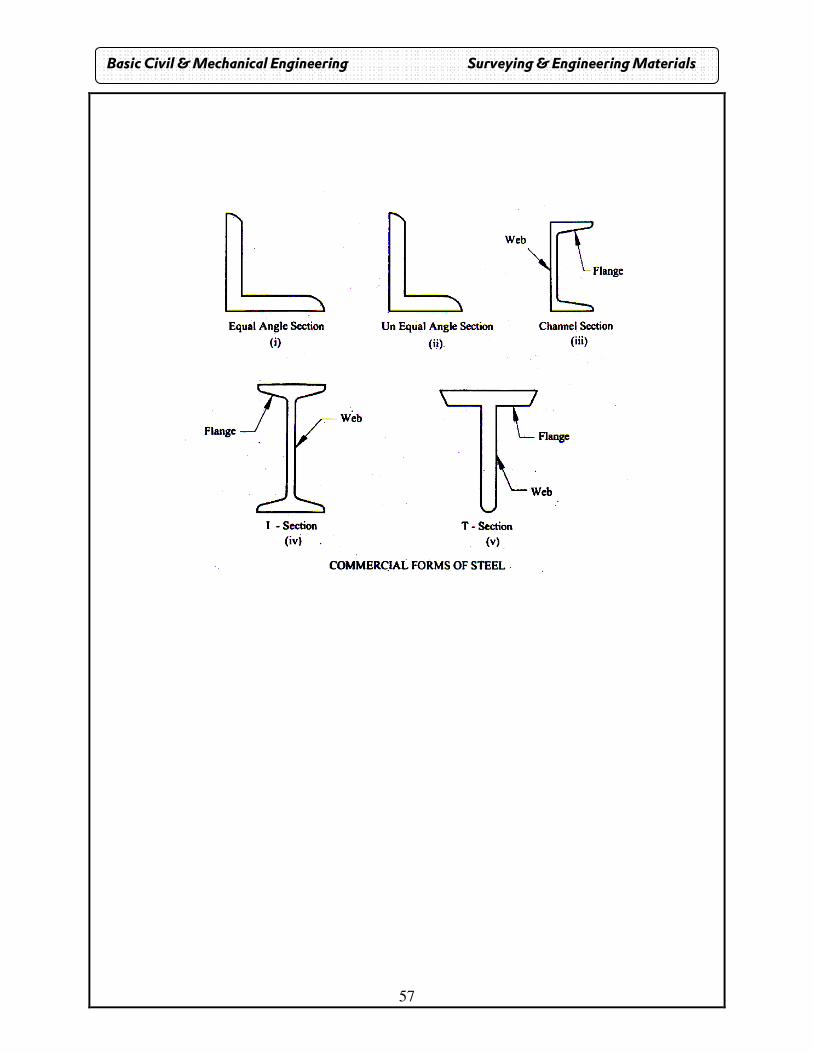
i. Angle section • The angle sections may be of equal legs or the unequal legs as shown in figure
a. Equal angle section: The equal angle sections available in size varying form 20 mm *20mm*3 mm to
200mm* 200mm*25 mm.the corresponding weights per meter length are respectively 9n t0 736 N.
b. Unequal sections The un-equal angle sections are available in sizes varying from
30 mm*20mm*3 mm to 200mm* 1500 mm*18 mm.the corresponding weights per meter length are respectively 11N and 469 N
Basic Civil & Mechanical Engineering Surveying & Engineering Materials
55
ii. Channel sections
• A channel sections is designed by the height of the web and width of flange .
• These sections are available in sizes varying from 100 mm* 45mm to 400 mm*
100mm.
• The corresponding weighs perimeter length is respectively 58 N and 494 N.
• Bridges etc.
v. Flat bars
These are available in suitable width varying from10mm to 400mm width thickness
varying from 3 mm to 4omm.they are widely used in the construction of bars.
vi. I-sections
• These are popularly known as the rolled steel joints beams (RSJ). If consists of two
flanges connected buy a web as shown in this fig,.
• It is designated by overall depth, width of flange and weight perimeter length.
• Varying of sizes: 75m x 50mm at 61 N to 600mm x 210 mm at995N.
• Joist of size 300mm x 150mm of 377N.The wide flange beams are available in sizes
varying from 150mm x 100 mm 170N to 600 mm x 250m at 1451N.
vii. Plates
• The plate sections of steel are available in different sizes of thickness
varying from 5mm to 50mm.
• The corresponding weights per square meter 392N and 3925N respectively.
i) To connect steel beams for extension of the length.
ii) To serve as tension members of steel roof truss and
iii) To form built up sections.
Basic Civil & Mechanical Engineering Surveying & Engineering Materials
56
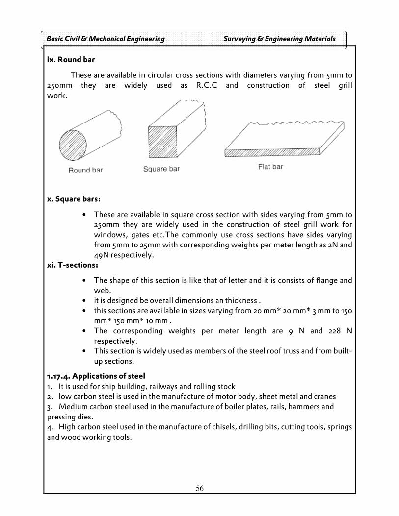
ix. Round bar
These are available in circular cross sections with diameters varying from 5mm to 250mm they are widely used as R.C.C and construction of steel grill work.
x. Square bars:
• These are available in square cross section with sides varying from 5mm to 250mm they are widely used in the construction of steel grill work for windows, gates etc.The commonly use cross sections have sides varying from 5mm to 25mm with corresponding weights per meter length as 2N and 49N respectively.
xi. T-sections:
• The shape of this section is like that of letter and it is consists of flange and web.
• it is designed be overall dimensions an thickness . • this sections are available in sizes varying from 20 mm* 20 mm* 3 mm to 150
mm* 150 mm* 10 mm . • The corresponding weights per meter length are 9 N and 228 N
respectively. • This section is widely used as members of the steel roof truss and from built-
up sections.
1.17.4. Applications of steel 1. It is used for ship building, railways and rolling stock 2. low carbon steel is used in the manufacture of motor body, sheet metal and cranes 3. Medium carbon steel used in the manufacture of boiler plates, rails, hammers and pressing dies. 4. High carbon steel used in the manufacture of chisels, drilling bits, cutting tools, springs and wood working tools.
Basic Civil & Mechanical Engineering Surveying & Engineering Materials
57
Basic Civil & Mechanical Engineering Surveying & Engineering Materials
58
UNIT II BUILDING COMPONENTS AND STRUCTURES
Building components
Building of structure has two components:
1 Foundation
2 Super structures
Foundation: The lower part of building, which is located below the ground leave.
Super structure: The part of building above the ground leave
Beaming capacity as soil: The maximum load per unit area that the soil will resist safely
without any displacement. It is used to determine 1) strength 2) behavior
Safe bearing capacity: maximum pressure which the soil can carry safely without shear
failure.
Increasing bearing capacity: 1) Increasing foundation depth 2) Drawing subsoil water 3)
compacting the soil
Functions of foundation: 1) to transmit the load 2) To avoid the failure
Requirements : 1) The foundation should be regid2) The foundation should be safe
against shear 3) The foundation should be strong to protect the building against
damage.4) Incase of foundation in slopping ground, the edges distance should be
sufficient to protect against corrosion 5) The foundation should not have difference in
level which can cause overlapping stress
Types of foundation: 1) Shallow 2) Deep
Shallow: It the depth as foundations equal to or less than its with, it is called shallow
Deep: equal (or) greater than………..
Types:1) Spread 2) combined 3) Strap 4)Mat (or) raft
Spread: Based on column 1) single footing 2) stepped 3) slopped
Single footing: If the base is provided with single column then it is known as single
footing
59
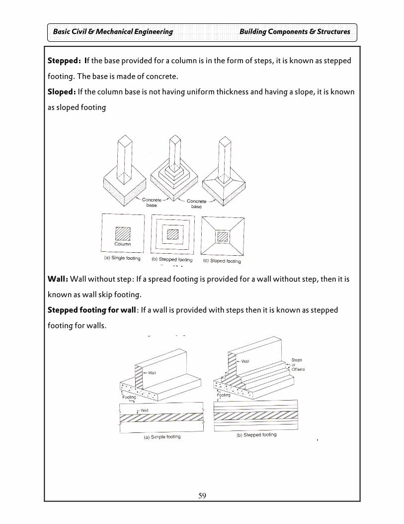
Stepped: If the base provided for a column is in the form of steps, it is known as stepped
footing. The base is made of concrete.
Sloped: If the column base is not having uniform thickness and having a slope, it is known
as sloped footing
Wall: Wall without step: If a spread footing is provided for a wall without step, then it is
known as wall skip footing.
Stepped footing for wall: If a wall is provided with steps then it is known as stepped
footing for walls.
.
Basic Civil & Mechanical Engineering Building Components & Structures
60
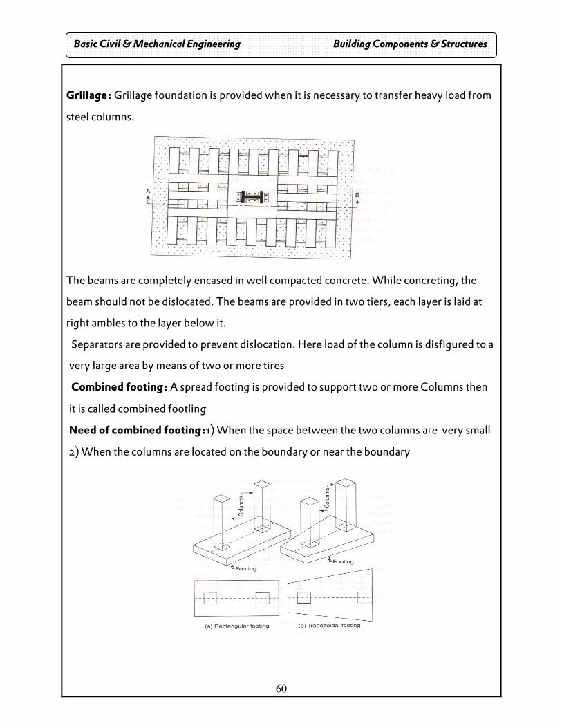
Grillage: Grillage foundation is provided when it is necessary to transfer heavy load from
steel columns.
The beams are completely encased in well compacted concrete. While concreting, the
beam should not be dislocated. The beams are provided in two tiers, each layer is laid at
right ambles to the layer below it.
Separators are provided to prevent dislocation. Here load of the column is disfigured to a
very large area by means of two or more tires
Combined footing: A spread footing is provided to support two or more Columns then
it is called combined footling
Need of combined footing:1) When the space between the two columns are very small
2) When the columns are located on the boundary or near the boundary
Basic Civil & Mechanical Engineering Building Components & Structures
61
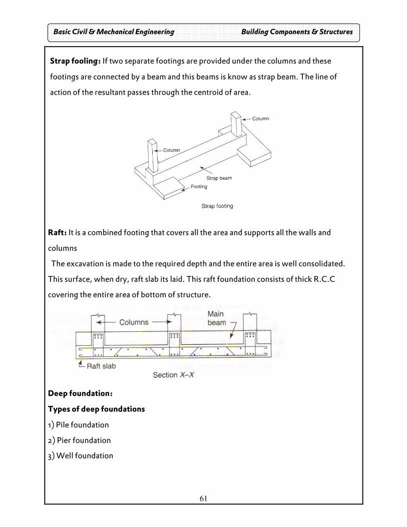
Strap fooling: If two separate footings are provided under the columns and these
footings are connected by a beam and this beams is know as strap beam. The line of
action of the resultant passes through the centroid of area.
Raft: It is a combined footing that covers all the area and supports all the walls and
columns
The excavation is made to the required depth and the entire area is well consolidated.
This surface, when dry, raft slab its laid. This raft foundation consists of thick R.C.C
covering the entire area of bottom of structure.
Deep foundation:
Types of deep foundations
1) Pile foundation
2) Pier foundation
3) Well foundation
Basic Civil & Mechanical Engineering Building Components & Structures
62
Pile foundation
When a soil of low bearing capacity for a greater depth and it is not possible to increase
the strength of soil by compaction, the loads are taken to a low level by means of vertical
members called piles, which may be timber, concrete or steel.
Need of pile foundation
1. Providing raft foundation is not economical
2. when pumping of subsoil is costly
3. load to be transmitted is large
4. When it is difficult to adopt normal foundation.
5. when considerable fluctuation of ground water level occurs seasonally
Classification of piles based on use
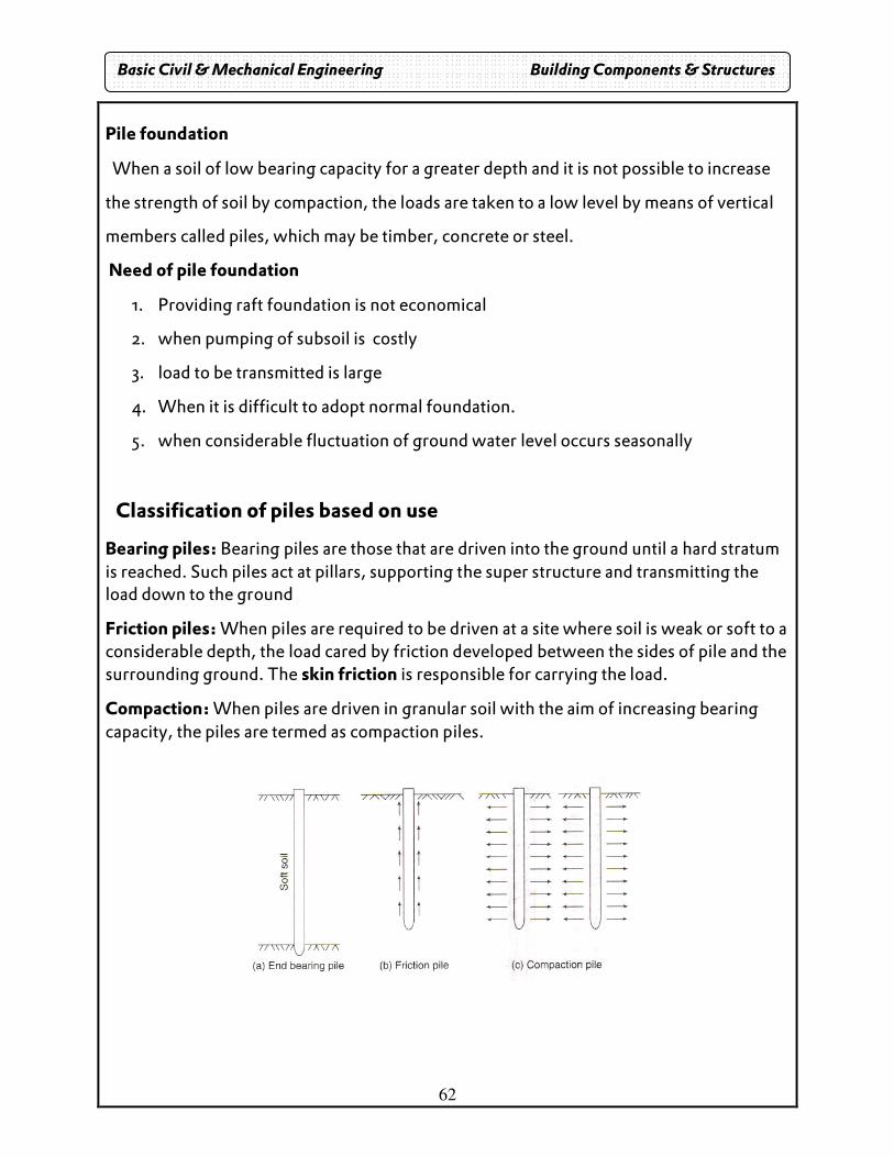
Bearing piles: Bearing piles are those that are driven into the ground until a hard stratum is reached. Such piles act at pillars, supporting the super structure and transmitting the load down to the ground
Friction piles: When piles are required to be driven at a site where soil is weak or soft to a considerable depth, the load cared by friction developed between the sides of pile and the surrounding ground. The skin friction is responsible for carrying the load.
Compaction: When piles are driven in granular soil with the aim of increasing bearing capacity, the piles are termed as compaction piles.
Basic Civil & Mechanical Engineering Building Components & Structures
63
Classification based on material:
1. Concrete
2. Timber
3. Steel
4. Composite
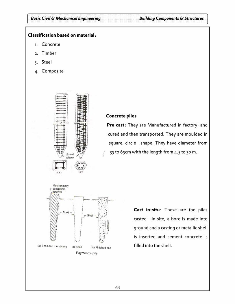
Concrete piles
Pre cast: They are Manufactured in factory, and
cured and then transported. They are moulded in
square, circle shape. They have diameter from
35 to 65cm with the length from 4.5 to 30 m.
Cast in-situ: These are the piles
casted in site, a bore is made into
ground and a casting or metallic shell
is inserted and cement concrete is
filled into the shell.
Basic Civil & Mechanical Engineering Building Components & Structures
64
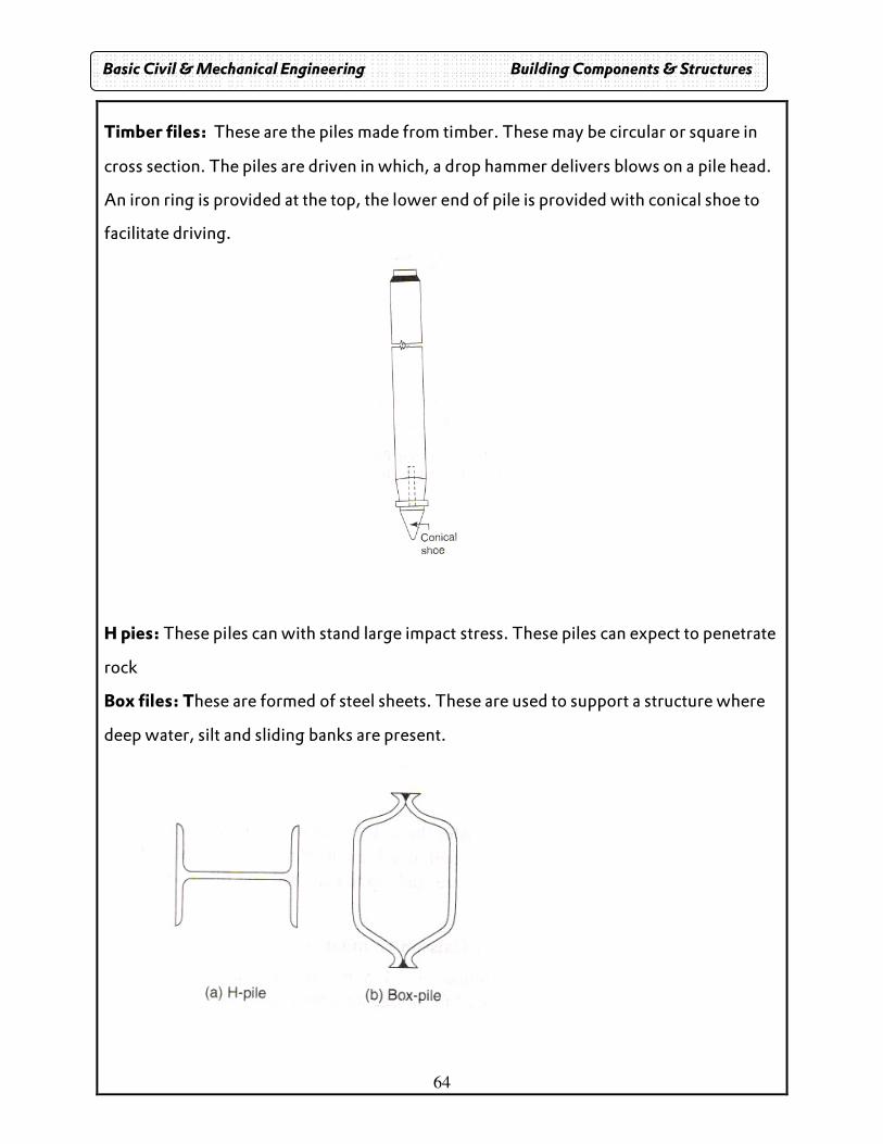
Timber files: These are the piles made from timber. These may be circular or square in
cross section. The piles are driven in which, a drop hammer delivers blows on a pile head.
An iron ring is provided at the top, the lower end of pile is provided with conical shoe to
facilitate driving.
H pies: These piles can with stand large impact stress. These piles can expect to penetrate
rock
Box files: These are formed of steel sheets. These are used to support a structure where
deep water, silt and sliding banks are present.
Basic Civil & Mechanical Engineering Building Components & Structures
65
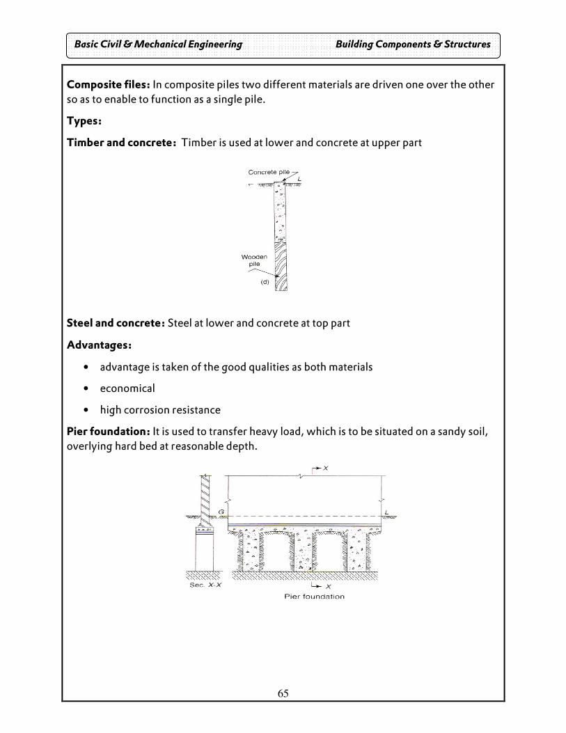
Composite files: In composite piles two different materials are driven one over the other so as to enable to function as a single pile.
Types:
Timber and concrete: Timber is used at lower and concrete at upper part
Steel and concrete: Steel at lower and concrete at top part
Advantages:
• advantage is taken of the good qualities as both materials
• economical
• high corrosion resistance
Pier foundation: It is used to transfer heavy load, which is to be situated on a sandy soil, overlying hard bed at reasonable depth.
Basic Civil & Mechanical Engineering Building Components & Structures
66
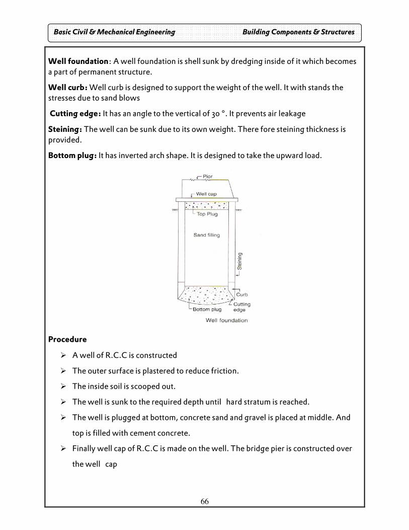
Well foundation: A well foundation is shell sunk by dredging inside of it which becomes a part of permanent structure.
Well curb: Well curb is designed to support the weight of the well. It with stands the stresses due to sand blows
Cutting edge: It has an angle to the vertical of 30 °. It prevents air leakage
Steining: The well can be sunk due to its own weight. There fore steining thickness is provided.
Bottom plug: It has inverted arch shape. It is designed to take the upward load.
Procedure
� A well of R.C.C is constructed
� The outer surface is plastered to reduce friction.
� The inside soil is scooped out.
� The well is sunk to the required depth until hard stratum is reached.
� The well is plugged at bottom, concrete sand and gravel is placed at middle. And
top is filled with cement concrete.
� Finally well cap of R.C.C is made on the well. The bridge pier is constructed over
the well cap
Basic Civil & Mechanical Engineering Building Components & Structures
67
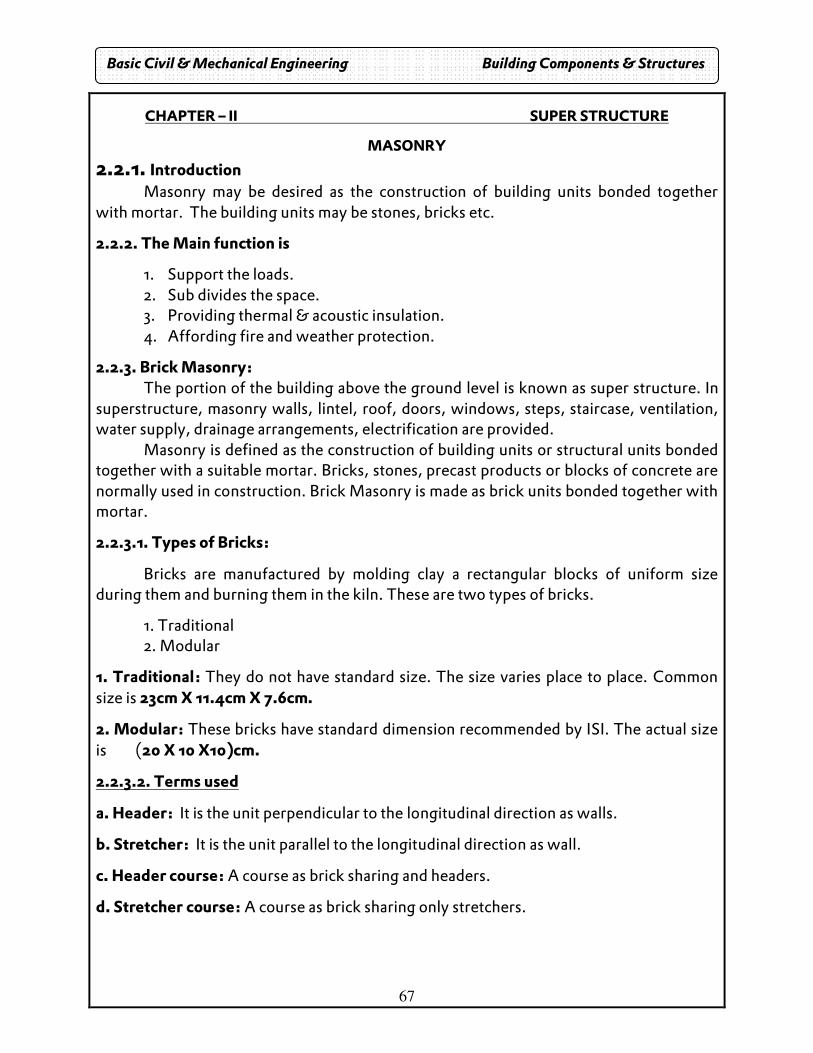
CHAPTER – II SUPER STRUCTURE
MASONRY
2.2.1. Introduction Masonry may be desired as the construction of building units bonded together with mortar. The building units may be stones, bricks etc.
2.2.2. The Main function is
1. Support the loads. 2. Sub divides the space. 3. Providing thermal & acoustic insulation. 4. Affording fire and weather protection.
2.2.3. Brick Masonry: The portion of the building above the ground level is known as super structure. In
superstructure, masonry walls, lintel, roof, doors, windows, steps, staircase, ventilation, water supply, drainage arrangements, electrification are provided.
Masonry is defined as the construction of building units or structural units bonded together with a suitable mortar. Bricks, stones, precast products or blocks of concrete are normally used in construction. Brick Masonry is made as brick units bonded together with mortar.
2.2.3.1. Types of Bricks:
Bricks are manufactured by molding clay a rectangular blocks of uniform size during them and burning them in the kiln. These are two types of bricks.
1. Traditional 2. Modular
1. Traditional: They do not have standard size. The size varies place to place. Common size is 23cm X 11.4cm X 7.6cm.
2. Modular: These bricks have standard dimension recommended by ISI. The actual size is (20 X 10 X10)cm.
2.2.3.2. Terms used
a. Header: It is the unit perpendicular to the longitudinal direction as walls.
b. Stretcher: It is the unit parallel to the longitudinal direction as wall.
c. Header course: A course as brick sharing and headers.
d. Stretcher course: A course as brick sharing only stretchers.
Basic Civil & Mechanical Engineering Building Components & Structures
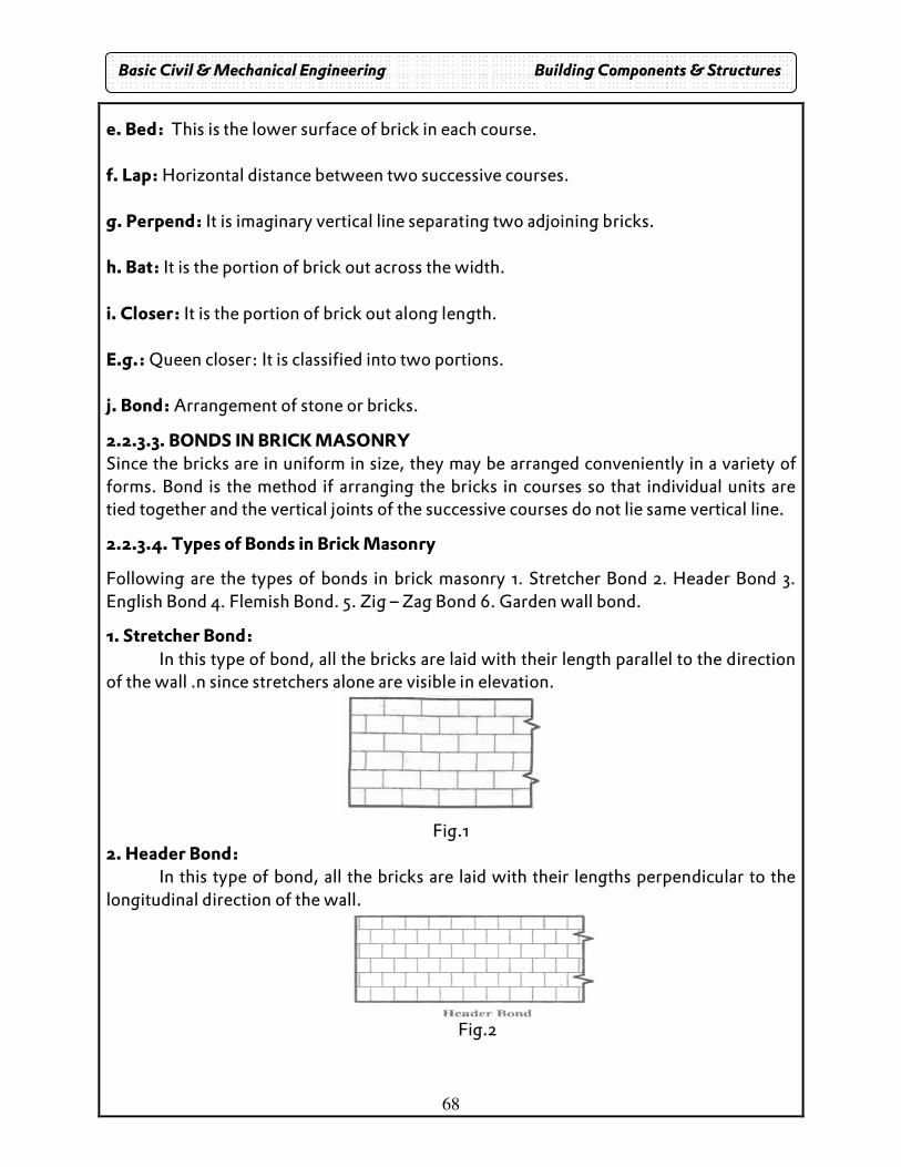
68
e. Bed: This is the lower surface of brick in each course. f. Lap: Horizontal distance between two successive courses. g. Perpend: It is imaginary vertical line separating two adjoining bricks. h. Bat: It is the portion of brick out across the width. i. Closer: It is the portion of brick out along length. E.g.: Queen closer: It is classified into two portions. j. Bond: Arrangement of stone or bricks.
2.2.3.3. BONDS IN BRICK MASONRY Since the bricks are in uniform in size, they may be arranged conveniently in a variety of forms. Bond is the method if arranging the bricks in courses so that individual units are tied together and the vertical joints of the successive courses do not lie same vertical line.
2.2.3.4. Types of Bonds in Brick Masonry
Following are the types of bonds in brick masonry 1. Stretcher Bond 2. Header Bond 3. English Bond 4. Flemish Bond. 5. Zig – Zag Bond 6. Garden wall bond.
1. Stretcher Bond: In this type of bond, all the bricks are laid with their length parallel to the direction of the wall .n since stretchers alone are visible in elevation.
Fig.1
2. Header Bond: In this type of bond, all the bricks are laid with their lengths perpendicular to the
longitudinal direction of the wall.
Fig.2
Basic Civil & Mechanical Engineering Building Components & Structures
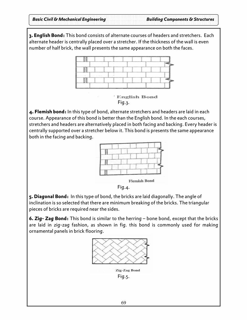
69
3. English Bond: This bond consists of alternate courses of headers and stretchers. Each alternate header is centrally placed over a stretcher. If the thickness of the wall is even number of half brick, the wall presents the same appearance on both the faces.
Fig.3.
4. Flemish bond: In this type of bond, alternate stretchers and headers are laid in each course. Appearance of this bond is better than the English bond. In the each courses, stretchers and headers are alternatively placed in both facing and backing. Every header is centrally supported over a stretcher below it. This bond is presents the same appearance both in the facing and backing.
Fig.4.
5. Diagonal Bond: In this type of bond, the bricks are laid diagonally. The angle of inclination is so selected that there are minimum breaking of the bricks. The triangular pieces of bricks are required near the sides.
6. Zig- Zag Bond: This bond is similar to the herring – bone bond, except that the bricks are laid in zig-zag fashion, as shown in fig. this bond is commonly used for making ornamental panels in brick flooring.
Fig.5.
Basic Civil & Mechanical Engineering Building Components & Structures
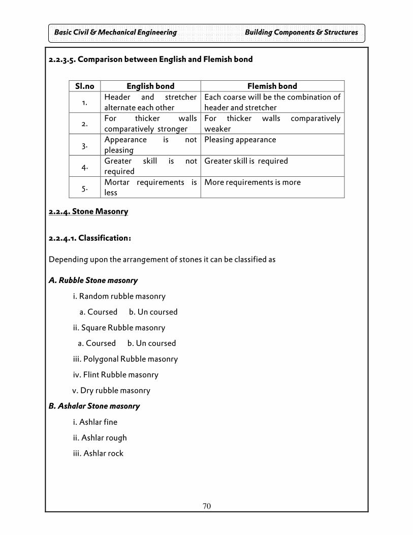
70
2.2.3.5. Comparison between English and Flemish bond
Sl.no English bond Flemish bond
1. Header and stretcher alternate each other
Each coarse will be the combination of header and stretcher
2. For thicker walls comparatively stronger
For thicker walls comparatively weaker
3. Appearance is not pleasing
Pleasing appearance
4. Greater skill is not required
Greater skill is required
5. Mortar requirements is less
More requirements is more
2.2.4. Stone Masonry
2.2.4.1. Classification: Depending upon the arrangement of stones it can be classified as A. Rubble Stone masonry
i. Random rubble masonry
a. Coursed b. Un coursed
ii. Square Rubble masonry
a. Coursed b. Un coursed
iii. Polygonal Rubble masonry
iv. Flint Rubble masonry
v. Dry rubble masonry
B. Ashalar Stone masonry
i. Ashlar fine
ii. Ashlar rough
iii. Ashlar rock
Basic Civil & Mechanical Engineering Building Components & Structures
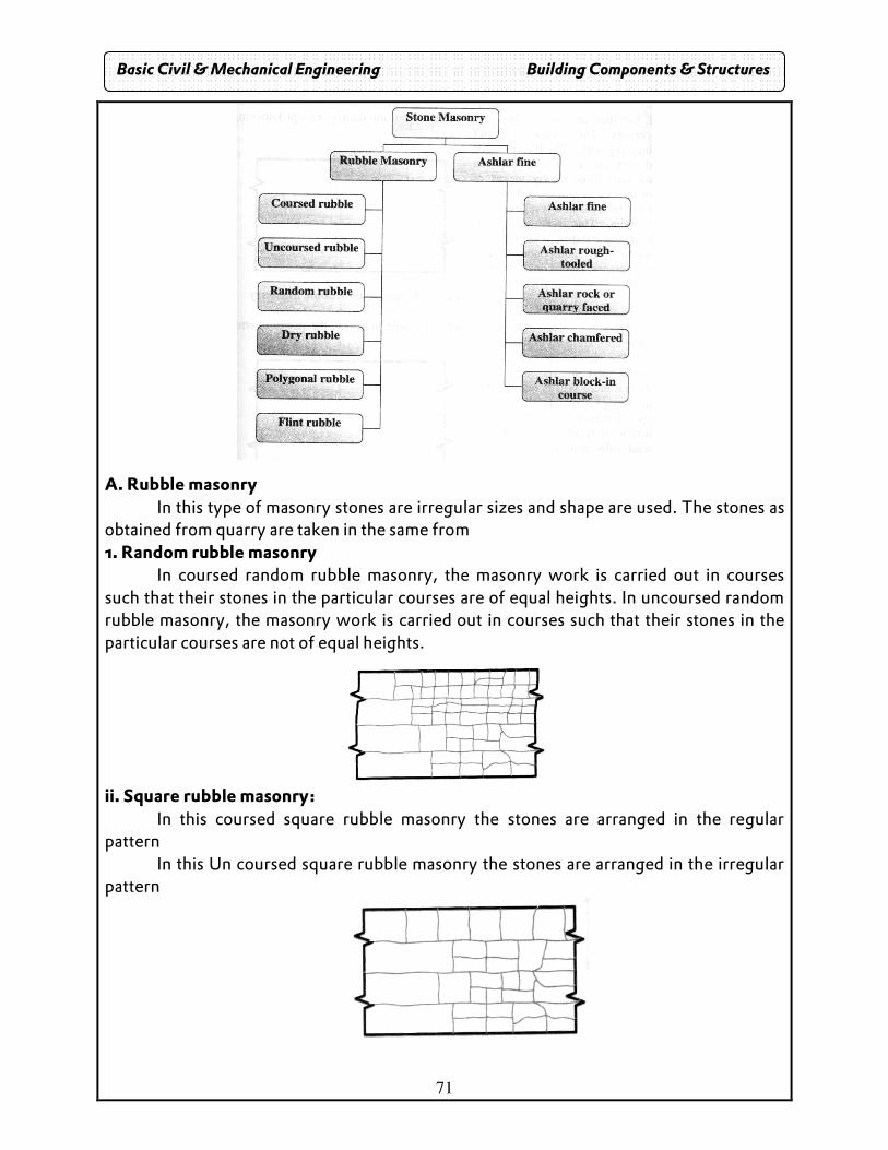
71
A. Rubble masonry In this type of masonry stones are irregular sizes and shape are used. The stones as obtained from quarry are taken in the same from 1. Random rubble masonry In coursed random rubble masonry, the masonry work is carried out in courses such that their stones in the particular courses are of equal heights. In uncoursed random rubble masonry, the masonry work is carried out in courses such that their stones in the particular courses are not of equal heights.
ii. Square rubble masonry: In this coursed square rubble masonry the stones are arranged in the regular pattern
In this Un coursed square rubble masonry the stones are arranged in the irregular pattern
Basic Civil & Mechanical Engineering Building Components & Structures
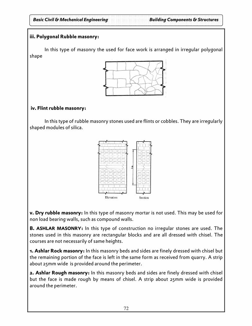
72
iii. Polygonal Rubble masonry:
In this type of masonry the used for face work is arranged in irregular polygonal shape
iv. Flint rubble masonry: In this type of rubble masonry stones used are flints or cobbles. They are irregularly shaped modules of silica.
v. Dry rubble masonry: In this type of masonry mortar is not used. This may be used for non load bearing walls, such as compound walls.
B. ASHLAR MASONRY: In this type of construction no irregular stones are used. The stones used in this masonry are rectangular blocks and are all dressed with chisel. The courses are not necessarily of same heights.
1. Ashlar Rock masonry: In this masonry beds and sides are finely dressed with chisel but the remaining portion of the face is left in the same form as received from quarry. A strip about 25mm wide is provided around the perimeter.
2. Ashlar Rough masonry: In this masonry beds and sides are finely dressed with chisel but the face is made rough by means of chisel. A strip about 25mm wide is provided around the perimeter.
Basic Civil & Mechanical Engineering Building Components & Structures
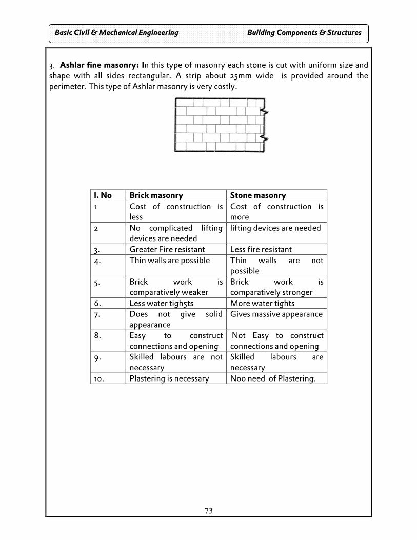
73
3. Ashlar fine masonry: In this type of masonry each stone is cut with uniform size and shape with all sides rectangular. A strip about 25mm wide is provided around the perimeter. This type of Ashlar masonry is very costly.
l. No Brick masonry Stone masonry 1 Cost of construction is
less Cost of construction is more
2 No complicated lifting devices are needed
lifting devices are needed
3. Greater Fire resistant Less fire resistant 4. Thin walls are possible Thin walls are not
possible 5. Brick work is
comparatively weaker Brick work is comparatively stronger
6. Less water tigh5ts More water tights 7. Does not give solid
appearance Gives massive appearance
8. Easy to construct connections and opening
Not Easy to construct connections and opening
9. Skilled labours are not necessary
Skilled labours are necessary
10. Plastering is necessary No0 need of Plastering.
Basic Civil & Mechanical Engineering Building Components & Structures
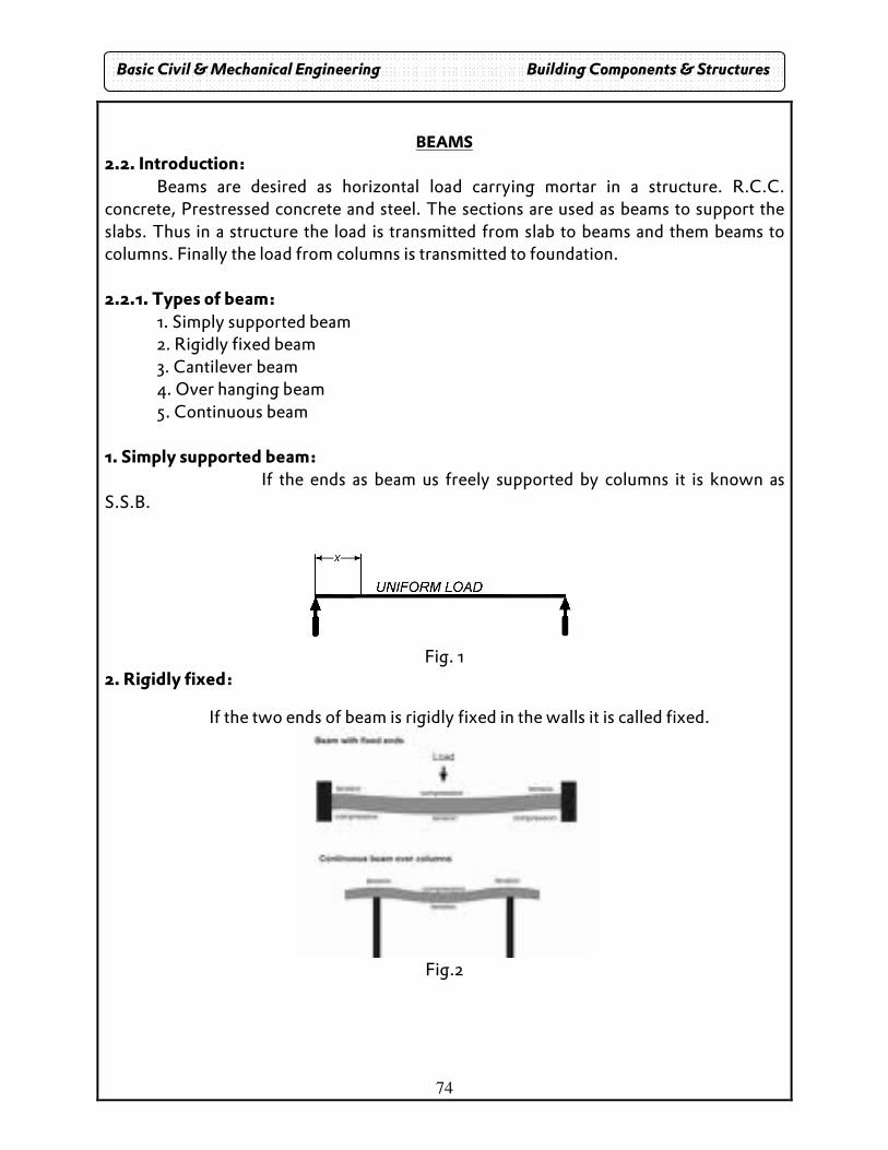
74
BEAMS
2.2. Introduction: Beams are desired as horizontal load carrying mortar in a structure. R.C.C. concrete, Prestressed concrete and steel. The sections are used as beams to support the slabs. Thus in a structure the load is transmitted from slab to beams and them beams to columns. Finally the load from columns is transmitted to foundation. 2.2.1. Types of beam: 1. Simply supported beam 2. Rigidly fixed beam 3. Cantilever beam 4. Over hanging beam 5. Continuous beam 1. Simply supported beam: If the ends as beam us freely supported by columns it is known as S.S.B.
Fig. 1
2. Rigidly fixed:
If the two ends of beam is rigidly fixed in the walls it is called fixed.
Fig.2
Basic Civil & Mechanical Engineering Building Components & Structures
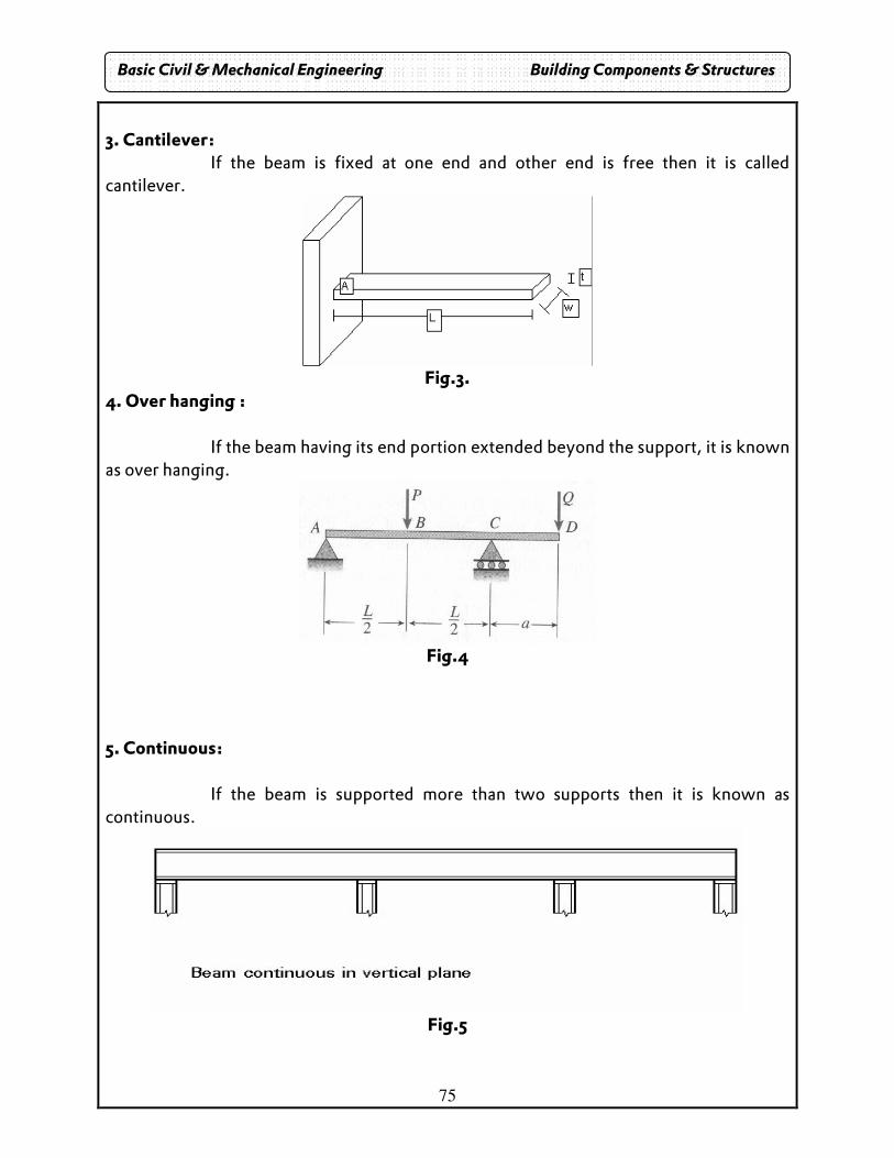
75
3. Cantilever: If the beam is fixed at one end and other end is free then it is called cantilever.
Fig.3.
4. Over hanging : If the beam having its end portion extended beyond the support, it is known as over hanging.
Fig.4
5. Continuous: If the beam is supported more than two supports then it is known as continuous.
Fig.5
Basic Civil & Mechanical Engineering Building Components & Structures
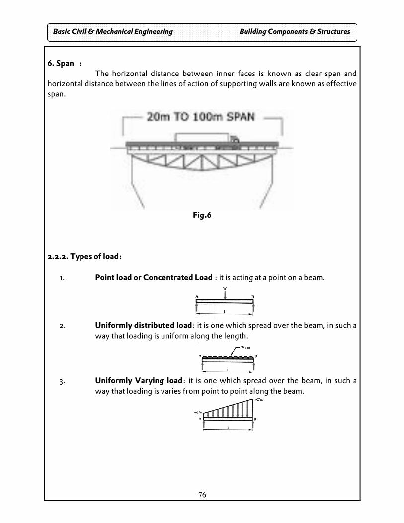
76
6. Span : The horizontal distance between inner faces is known as clear span and horizontal distance between the lines of action of supporting walls are known as effective span.
Fig.6
2.2.2. Types of load:
1. Point load or Concentrated Load : it is acting at a point on a beam.
2. Uniformly distributed load: it is one which spread over the beam, in such a
way that loading is uniform along the length.
3. Uniformly Varying load: it is one which spread over the beam, in such a
way that loading is varies from point to point along the beam.
Basic Civil & Mechanical Engineering Building Components & Structures
77
COLUMNS
2.3. General
Any structural member or elements used to support compressive loads is called column. The columns have various shapes, such as square, rectangular, circular, hexagonal and octagonal. They are constructed of timber, brick, and stone, reinforced cement concrete and steel sections.
R.C.C. columns and steel columns are commonly used. R.C.C columns are used in R.C.C columns are used in R.C.C framed structures and steel columns are used in steel frames. In the framed structure, the columns transfer the load from the slab or roof, beam, live and all dead loads to the foundation.
The failure of the column depends on the length of the member compared to its cross-sectional dimension.
The vertical load carrying member is called column. E.g. R.C.C. and steel. 2.3.1. Slenderness Ratio
The ratio of effective length of the column to its least lateral dimension is called slenderness ratio.
The effective length of the column depends end condition of the column. Based on the slenderness ratio, the column are classified into long column and short column 2.3.2. Types:
1. Long column
2. Short column
1. Long column: Left / r <= 12, in the long column, the ultimate load is influenced by slenderness. This causes the additional bending due to transverse deformations. The long column fails by buckling. 2. Short column: Left / r > 12, in the short column, the strength of the materials and dimensions of cross section govern the ultimate load. The short column fails by yielding or crushing.
Basic Civil & Mechanical Engineering Building Components & Structures
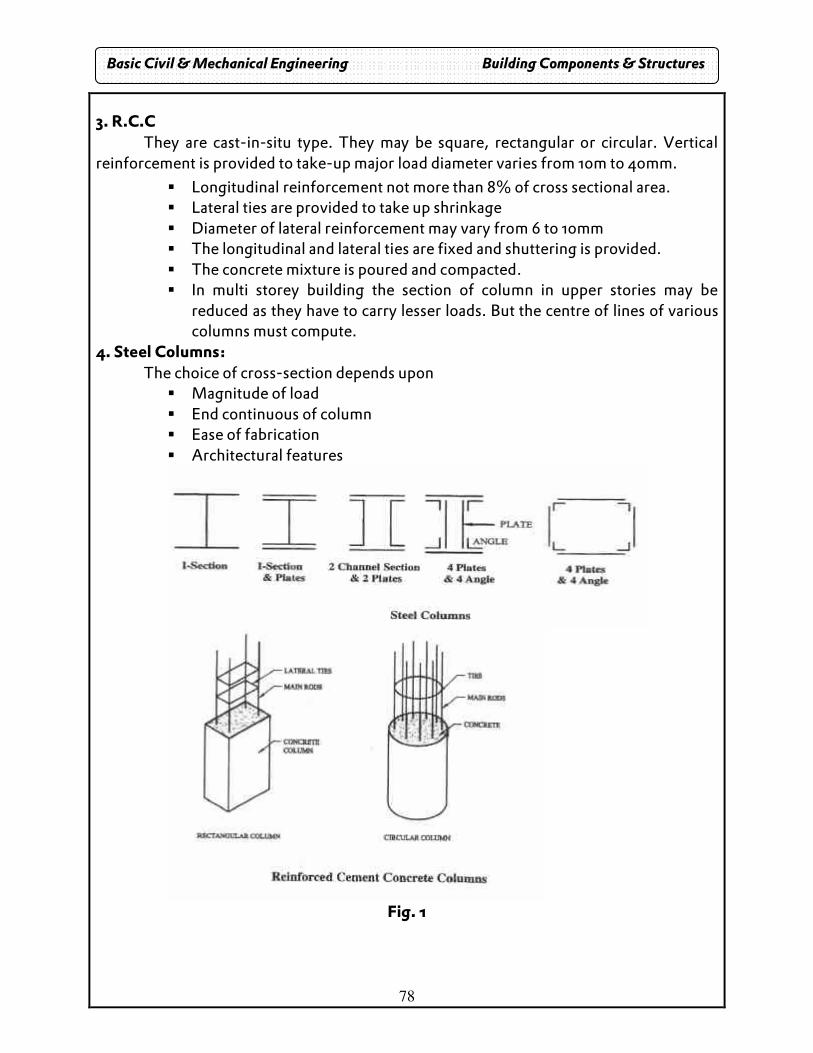
78
3. R.C.C They are cast-in-situ type. They may be square, rectangular or circular. Vertical reinforcement is provided to take-up major load diameter varies from 10m to 40mm.
� Longitudinal reinforcement not more than 8% of cross sectional area. � Lateral ties are provided to take up shrinkage � Diameter of lateral reinforcement may vary from 6 to 10mm � The longitudinal and lateral ties are fixed and shuttering is provided. � The concrete mixture is poured and compacted. � In multi storey building the section of column in upper stories may be
reduced as they have to carry lesser loads. But the centre of lines of various columns must compute.
4. Steel Columns: The choice of cross-section depends upon
� Magnitude of load � End continuous of column � Ease of fabrication � Architectural features
Fig. 1
Basic Civil & Mechanical Engineering Building Components & Structures
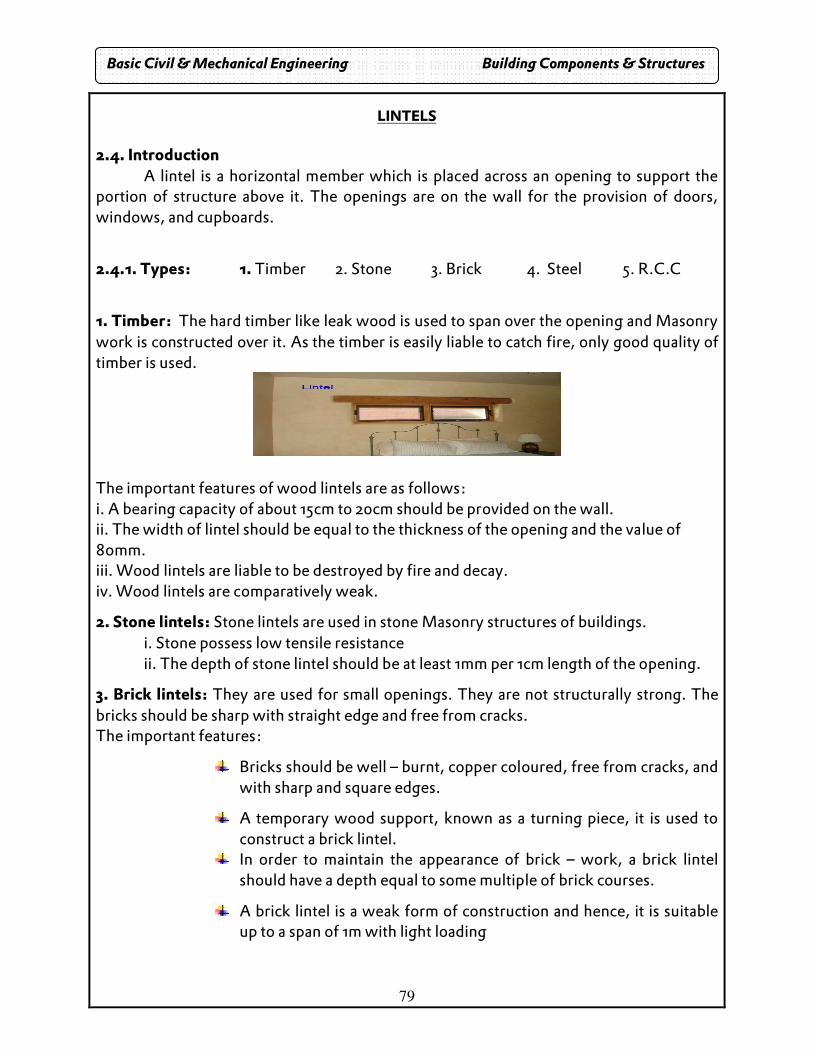
79
LINTELS
2.4. Introduction A lintel is a horizontal member which is placed across an opening to support the portion of structure above it. The openings are on the wall for the provision of doors, windows, and cupboards.
2.4.1. Types: 1. Timber 2. Stone 3. Brick 4. Steel 5. R.C.C
1. Timber: The hard timber like leak wood is used to span over the opening and Masonry work is constructed over it. As the timber is easily liable to catch fire, only good quality of timber is used.
The important features of wood lintels are as follows: i. A bearing capacity of about 15cm to 20cm should be provided on the wall. ii. The width of lintel should be equal to the thickness of the opening and the value of 80mm. iii. Wood lintels are liable to be destroyed by fire and decay. iv. Wood lintels are comparatively weak.
2. Stone lintels: Stone lintels are used in stone Masonry structures of buildings. i. Stone possess low tensile resistance ii. The depth of stone lintel should be at least 1mm per 1cm length of the opening.
3. Brick lintels: They are used for small openings. They are not structurally strong. The bricks should be sharp with straight edge and free from cracks. The important features:
Bricks should be well – burnt, copper coloured, free from cracks, and with sharp and square edges.
A temporary wood support, known as a turning piece, it is used to construct a brick lintel.
In order to maintain the appearance of brick – work, a brick lintel should have a depth equal to some multiple of brick courses.
A brick lintel is a weak form of construction and hence, it is suitable up to a span of 1m with light loading
Basic Civil & Mechanical Engineering Building Components & Structures
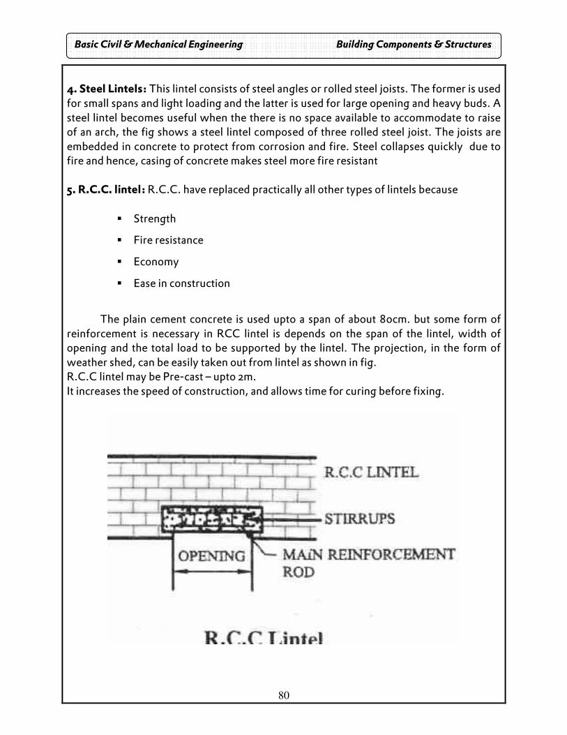
80
4. Steel Lintels: This lintel consists of steel angles or rolled steel joists. The former is used for small spans and light loading and the latter is used for large opening and heavy buds. A steel lintel becomes useful when the there is no space available to accommodate to raise of an arch, the fig shows a steel lintel composed of three rolled steel joist. The joists are embedded in concrete to protect from corrosion and fire. Steel collapses quickly due to fire and hence, casing of concrete makes steel more fire resistant 5. R.C.C. lintel: R.C.C. have replaced practically all other types of lintels because
� Strength
� Fire resistance
� Economy
� Ease in construction
The plain cement concrete is used upto a span of about 80cm. but some form of
reinforcement is necessary in RCC lintel is depends on the span of the lintel, width of opening and the total load to be supported by the lintel. The projection, in the form of weather shed, can be easily taken out from lintel as shown in fig. R.C.C lintel may be Pre-cast – upto 2m. It increases the speed of construction, and allows time for curing before fixing.
Basic Civil & Mechanical Engineering Building Components & Structures
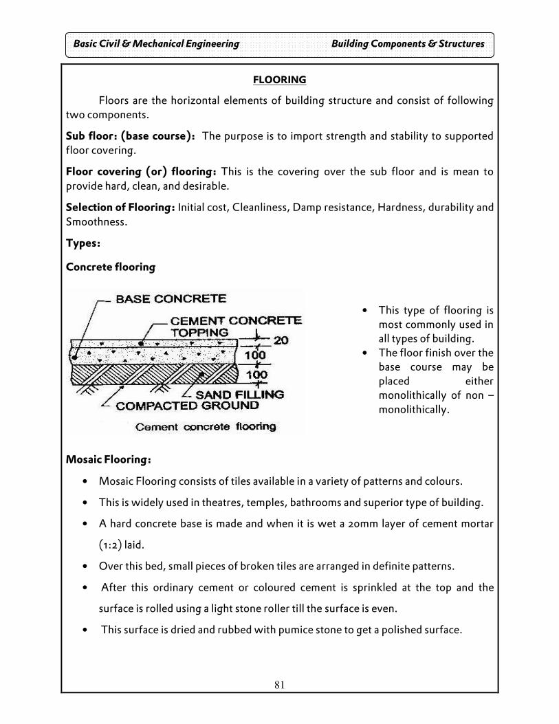
81
FLOORING
Floors are the horizontal elements of building structure and consist of following two components.
Sub floor: (base course): The purpose is to import strength and stability to supported floor covering.
Floor covering (or) flooring: This is the covering over the sub floor and is mean to provide hard, clean, and desirable.
Selection of Flooring: Initial cost, Cleanliness, Damp resistance, Hardness, durability and Smoothness.
Types:
Concrete flooring
• This type of flooring is
most commonly used in all types of building.
• The floor finish over the base course may be placed either monolithically of non – monolithically.
Mosaic Flooring:
• Mosaic Flooring consists of tiles available in a variety of patterns and colours.
• This is widely used in theatres, temples, bathrooms and superior type of building.
• A hard concrete base is made and when it is wet a 20mm layer of cement mortar
(1:2) laid.
• Over this bed, small pieces of broken tiles are arranged in definite patterns.
• After this ordinary cement or coloured cement is sprinkled at the top and the
surface is rolled using a light stone roller till the surface is even.
• This surface is dried and rubbed with pumice stone to get a polished surface.
Basic Civil & Mechanical Engineering Building Components & Structures
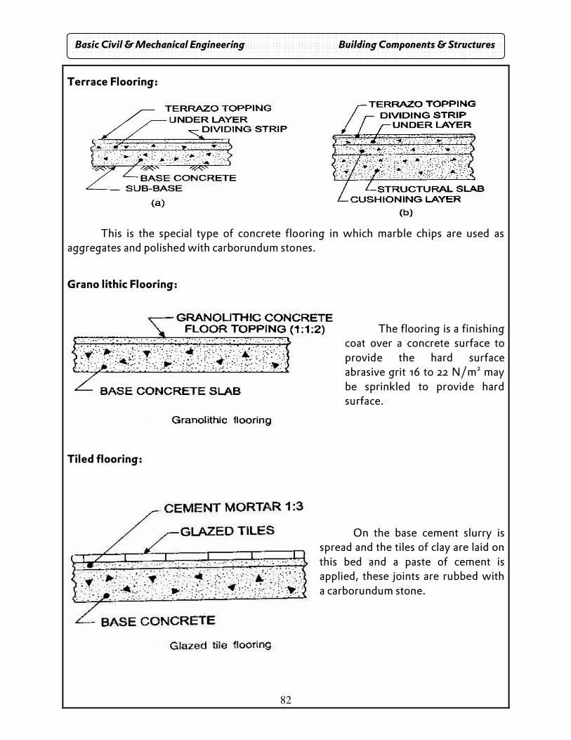
82
Terrace Flooring:
This is the special type of concrete flooring in which marble chips are used as aggregates and polished with carborundum stones.
Grano lithic Flooring:
The flooring is a finishing coat over a concrete surface to provide the hard surface abrasive grit 16 to 22 N/m2 may be sprinkled to provide hard surface.
Tiled flooring:
On the base cement slurry is spread and the tiles of clay are laid on this bed and a paste of cement is applied, these joints are rubbed with a carborundum stone.
Basic Civil & Mechanical Engineering Building Components & Structures
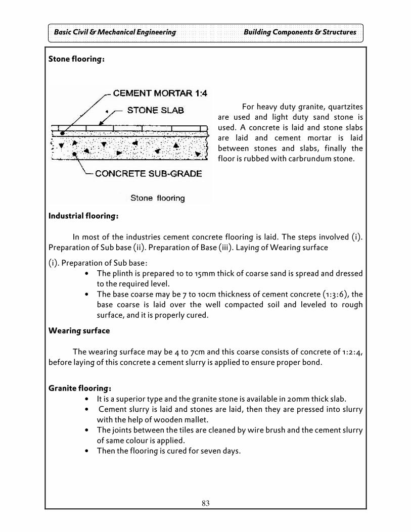
83
Stone flooring:
For heavy duty granite, quartzites are used and light duty sand stone is used. A concrete is laid and stone slabs are laid and cement mortar is laid between stones and slabs, finally the floor is rubbed with carbrundum stone.
Industrial flooring: In most of the industries cement concrete flooring is laid. The steps involved (i). Preparation of Sub base (ii). Preparation of Base (iii). Laying of Wearing surface
(i). Preparation of Sub base: • The plinth is prepared 10 to 15mm thick of coarse sand is spread and dressed
to the required level. • The base coarse may be 7 to 10cm thickness of cement concrete (1:3:6), the
base coarse is laid over the well compacted soil and leveled to rough surface, and it is properly cured.
Wearing surface
The wearing surface may be 4 to 7cm and this coarse consists of concrete of 1:2:4, before laying of this concrete a cement slurry is applied to ensure proper bond.
Granite flooring: • It is a superior type and the granite stone is available in 20mm thick slab. • Cement slurry is laid and stones are laid, then they are pressed into slurry
with the help of wooden mallet. • The joints between the tiles are cleaned by wire brush and the cement slurry
of same colour is applied. • Then the flooring is cured for seven days.
Basic Civil & Mechanical Engineering Building Components & Structures
84
PLASTERING
Plastering is the process of covering rough walls and uneven surfaces.
Objectives: To provide smooth surface
To conceal defective workmanship.
To protect the surface from the atmospheric agencies.
To provide satisfactory base for white washing.
Requirements of Good Plastering:
� It should not shrink while drying.
� It should adhere firmly.
� It should provide decorative appearance.
Types of plastering:
Cement plastering: It is a mixture of cement and sand, and the ratio depends upon the nature of work.
Mud Plaster: It is the mixture of clay, bricks, loose soil and chopped straw, and hemp, this is mixed with water and left for 7 days and then it is again mixed and applied.
Lime plaster: Equal volumes of lime and sand is used, sand used for plaster should be clean and free from organic impurities to improve the strength a small quantity cement is also added.
Water proof plaster:
• One part of cement and two part s of sand and pulverized alum. • In order to make water proof soap water is used.
Method:
• The m0rtar joints racked out to a depth of 20mm and the surface is cleaned and well watered.
• A preliminary coat is applied and the first coat of plaster is now applied with a thickness of 9 to 10mm.
• The second coat is applied after 6 hours and the thickness will be 3 to 12mm. • The complete process is allowed to set for 24 hours and it is well watered for at
least one week.
Basic Civil & Mechanical Engineering Building Components & Structures
85
Defects of plastering:
• Formation of cracks due to improper preparation of background surface, structural
defects, etc.
• Multiple hair cracks seen on plastered surface known as crazing.
• Flaking or peeling due to imperfect bond between successive coats of plaster.
• Bubble like swelling or blistering of plastered surface seen mostly on the inner
surfaces.
• Uneven or undulating surface due to poor workmanship.
• Formation of efflorescence (white crystalline substance seen on the surface) due
to the presence of salts in plaster materials, bricks, sand and /or water used.
Basic Civil & Mechanical Engineering Building Components & Structures
86
MECHANICS Stress and its types
• When a body is acted upon by some load (or) external force, it undergoes deformation (i.e. change in shape or dimensions)
• Stress is defined as the internal resistance offered by the material to the extremely applied force, expressed per unit area.
A
P=σ
tionofAreaA
loadappliedP
stress
sec=
=
=σ
Types of stresses:
1. Axial stress 2. Bearing stress 3. Bending stress 4. Shear stress
Types of axial stress:
1. Tensile stress 2. Compressive stress.
Strain. Strain is defined as the ratio of change in length to the original length of the member
Change in length (dl) Strain = Original length (l)
Tensile stress and tensile strain.
When the resistance offered by a section of a member is against an increase in length, the section is said to offer tensile stress.
Tensile stress ( )A
p
ASC
ceresisInternalt
==..
tanσ
Tensile strain:
The strain corresponding to tensile stress is tensile strain.
lengthOriginal
lengthIncrease
l
lestrainTensile ==
σ
Basic Civil & Mechanical Engineering Building Components & Structures
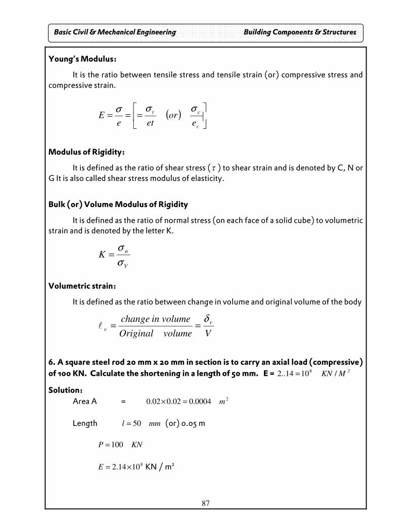
87
Young’s Modulus:
It is the ratio between tensile stress and tensile strain (or) compressive stress and compressive strain.
( )
===
c
ct
eor
eteE
σσσ
Modulus of Rigidity:
It is defined as the ratio of shear stress (τ ) to shear strain and is denoted by C, N or G It is also called shear stress modulus of elasticity.
Bulk (or) Volume Modulus of Rigidity
It is defined as the ratio of normal stress (on each face of a solid cube) to volumetric strain and is denoted by the letter K.
V
nK
σ
σ=
Volumetric strain:
It is defined as the ratio between change in volume and original volume of the body
VvolumeOriginal
volumeinchange v
v
δ==l
6. A square steel rod 20 mm x 20 mm in section is to carry an axial load (compressive)
of 100 KN. Calculate the shortening in a length of 50 mm. E = 28/1014..2 MKN=
Solution: Area A = 2
0004.002.002.0 m=×
Length mml 50= (or) 0.05 m
KNP 100=
8
1014.2 ×=E KN / m2
Basic Civil & Mechanical Engineering Building Components & Structures
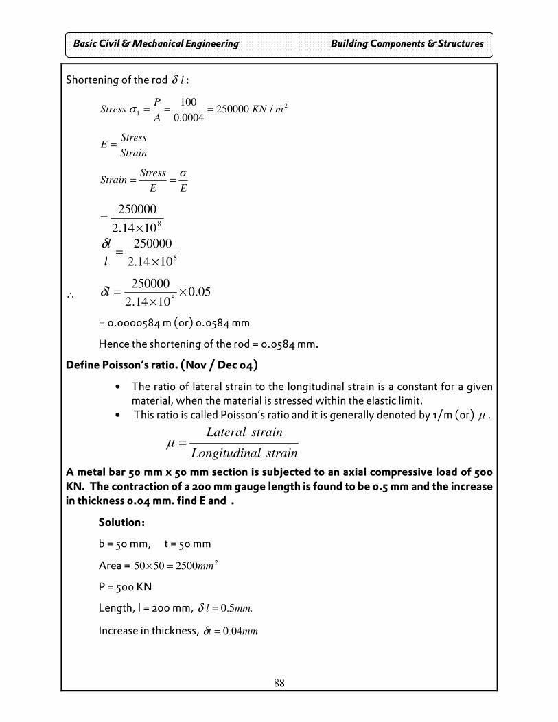
88
Shortening of the rod :lδ
2
1/250000
0004.0
100mKN
A
PStress ===σ
Strain
StressE =
EE
StressStrain
σ==
8
1014.2
250000
×=
8
1014.2
250000
×=
l
lδ
∴ 05.01014.2
250000
8×
×=lδ
= 0.0000584 m (or) 0.0584 mm
Hence the shortening of the rod = 0.0584 mm.
Define Poisson’s ratio. (Nov / Dec 04)
• The ratio of lateral strain to the longitudinal strain is a constant for a given material, when the material is stressed within the elastic limit.
• This ratio is called Poisson’s ratio and it is generally denoted by 1/m (or) µ .
strainalLongitudin
strainLateral=µ
A metal bar 50 mm x 50 mm section is subjected to an axial compressive load of 500 KN. The contraction of a 200 mm gauge length is found to be 0.5 mm and the increase in thickness 0.04 mm. find E and .
Solution:
b = 50 mm, t = 50 mm
Area = 225005050 mm=×
P = 500 KN
Length, l = 200 mm, .5.0 mml =δ
Increase in thickness, mmt 04.0=δ
Basic Civil & Mechanical Engineering Building Components & Structures
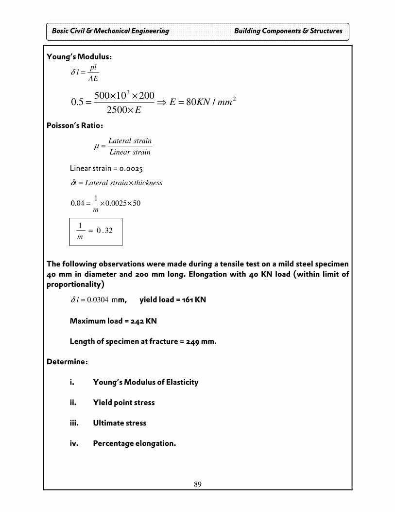
89
Young’s Modulus:
AE
pll =δ
2
3
/802500
200105005.0 mmKNE
E=⇒
×
××=
Poisson’s Ratio:
strainLinear
strainLateral=µ
Linear strain = 0.0025
thicknessstrainLateralt ×=δ
500025.01
04.0 ××=m
The following observations were made during a tensile test on a mild steel specimen 40 mm in diameter and 200 mm long. Elongation with 40 KN load (within limit of proportionality)
0304.0=lδ mm, yield load = 161 KN
Maximum load = 242 KN Length of specimen at fracture = 249 mm. Determine:
i. Young’s Modulus of Elasticity ii. Yield point stress iii. Ultimate stress iv. Percentage elongation.
32.01
=m
Basic Civil & Mechanical Engineering Building Components & Structures
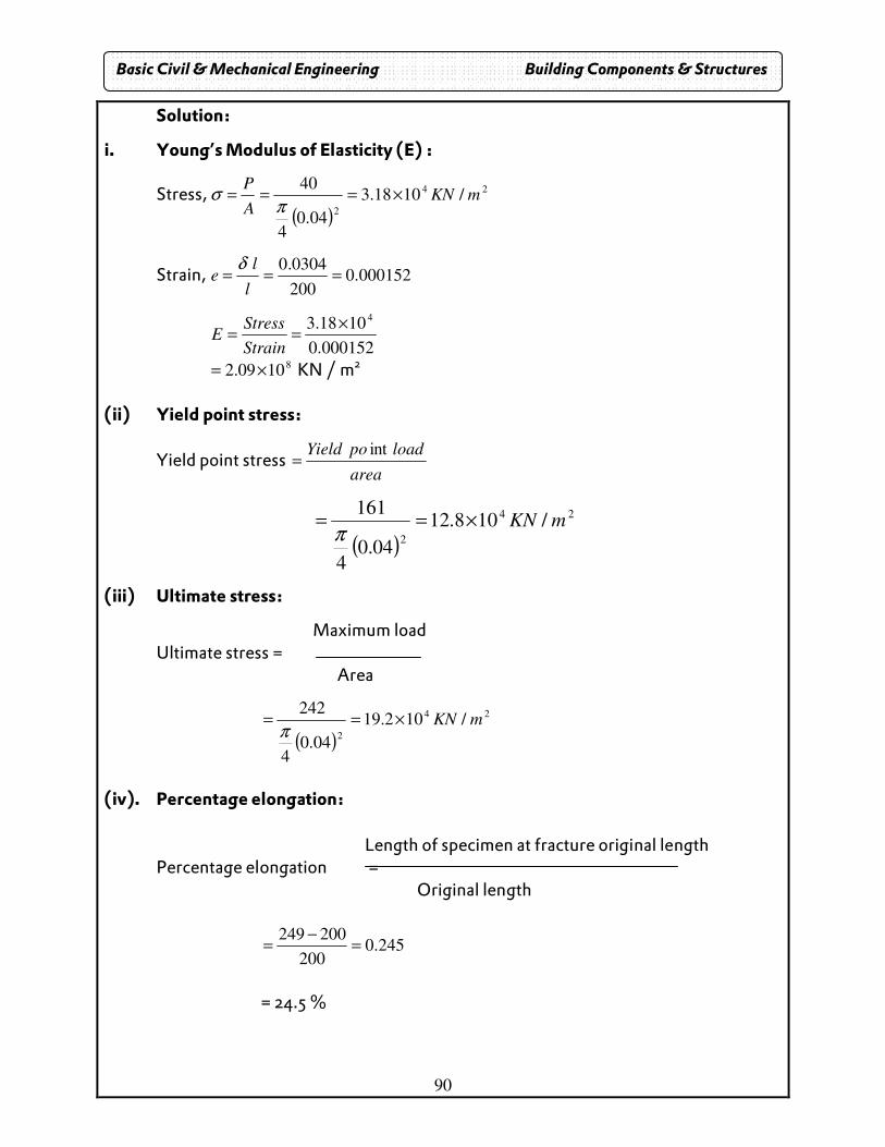
90
Solution:
i. Young’s Modulus of Elasticity (E) :
Stress, ( )
24
2
/1018.3
04.04
40mKN
A
P×===
πσ
Strain, 000152.0200
0304.0===
l
le
δ
000152.0
1018.34×
==Strain
StressE
81009.2 ×= KN / m2
(ii) Yield point stress:
Yield point stress area
loadpoYield int=
( )
24
2
/108.12
04.04
161mKN×==
π
(iii) Ultimate stress:
Maximum load Ultimate stress = Area
( )
24
2
/102.19
04.04
242mKN×==
π
(iv). Percentage elongation: Length of specimen at fracture original length Percentage elongation = Original length
245.0200
200249=
−=
= 24.5 %
Basic Civil & Mechanical Engineering Building Components & Structures
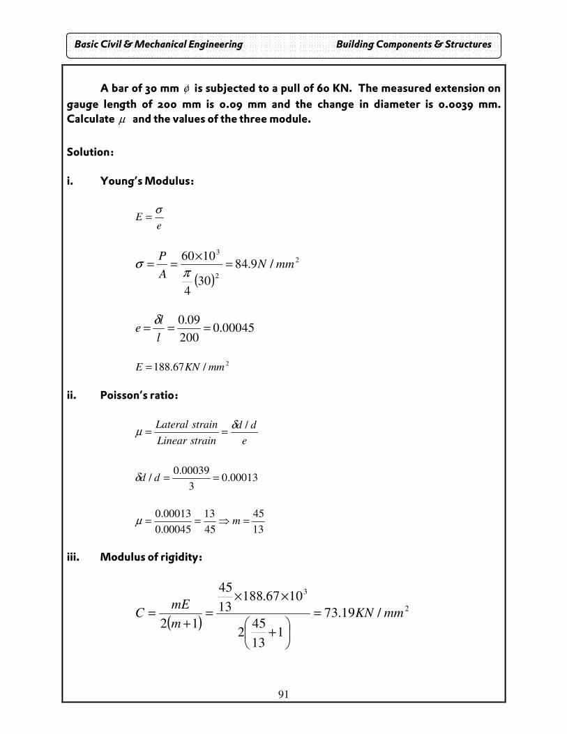
91
A bar of 30 mm φ is subjected to a pull of 60 KN. The measured extension on
gauge length of 200 mm is 0.09 mm and the change in diameter is 0.0039 mm. Calculate µ and the values of the three module.
Solution: i. Young’s Modulus:
e
Eσ
=
( )
2
2
3
/9.84
304
1060mmN
A
P=
×==
πσ
00045.0200
09.0===
l
le
δ
2
/67.188 mmKNE = ii. Poisson’s ratio:
e
dd
strainLinear
strainLateral /δµ ==
00013.03
00039.0/ ==ddδ
13
45
45
13
00045.0
00013.0=⇒== mµ
iii. Modulus of rigidity:
( )2
3
/19.73
113
452
1067.18813
45
12mmKN
m
mEC =
+
××
=+
=
Basic Civil & Mechanical Engineering Building Components & Structures
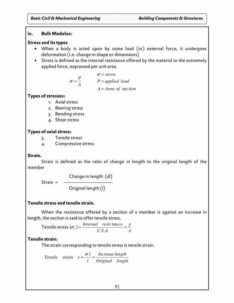
92
iv. Bulk Modulus:
Stress and its types • When a body is acted upon by some load (or) external force, it undergoes
deformation (i.e. change in shape or dimensions) • Stress is defined as the internal resistance offered by the material to the extremely
applied force, expressed per unit area.
A
P=σ
tionofAreaA
loadappliedP
stress
sec=
=
=σ
Types of stresses: 1. Axial stress 2. Bearing stress 3. Bending stress 4. Shear stress
Types of axial stress: 3. Tensile stress 4. Compressive stress.
Strain. Strain is defined as the ratio of change in length to the original length of the member
Change in length (dl) Strain = Original length (l)
Tensile stress and tensile strain.
When the resistance offered by a section of a member is against an increase in length, the section is said to offer tensile stress.
Tensile stress ( )A
p
ASC
ceresisInternalt
==..
tanσ
Tensile strain: The strain corresponding to tensile stress is tensile strain.
lengthOriginal
lengthIncrease
l
lestrainTensile ==
σ
Basic Civil & Mechanical Engineering Building Components & Structures
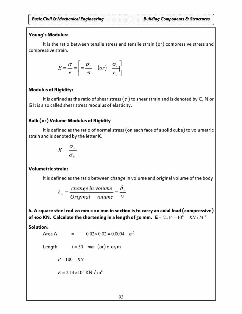
93
Young’s Modulus:
It is the ratio between tensile stress and tensile strain (or) compressive stress and compressive strain.
( )
===
c
ct
eor
eteE
σσσ
Modulus of Rigidity:
It is defined as the ratio of shear stress (τ ) to shear strain and is denoted by C, N or G It is also called shear stress modulus of elasticity.
Bulk (or) Volume Modulus of Rigidity
It is defined as the ratio of normal stress (on each face of a solid cube) to volumetric strain and is denoted by the letter K.
V
nK
σ
σ=
Volumetric strain:
It is defined as the ratio between change in volume and original volume of the body
VvolumeOriginal
volumeinchange v
v
δ==l
6. A square steel rod 20 mm x 20 mm in section is to carry an axial load (compressive)
of 100 KN. Calculate the shortening in a length of 50 mm. E = 28/1014..2 MKN=
Solution:
Area A = 20004.002.002.0 m=×
Length mml 50= (or) 0.05 m
KNP 100=
8
1014.2 ×=E KN / m2
Basic Civil & Mechanical Engineering Building Components & Structures
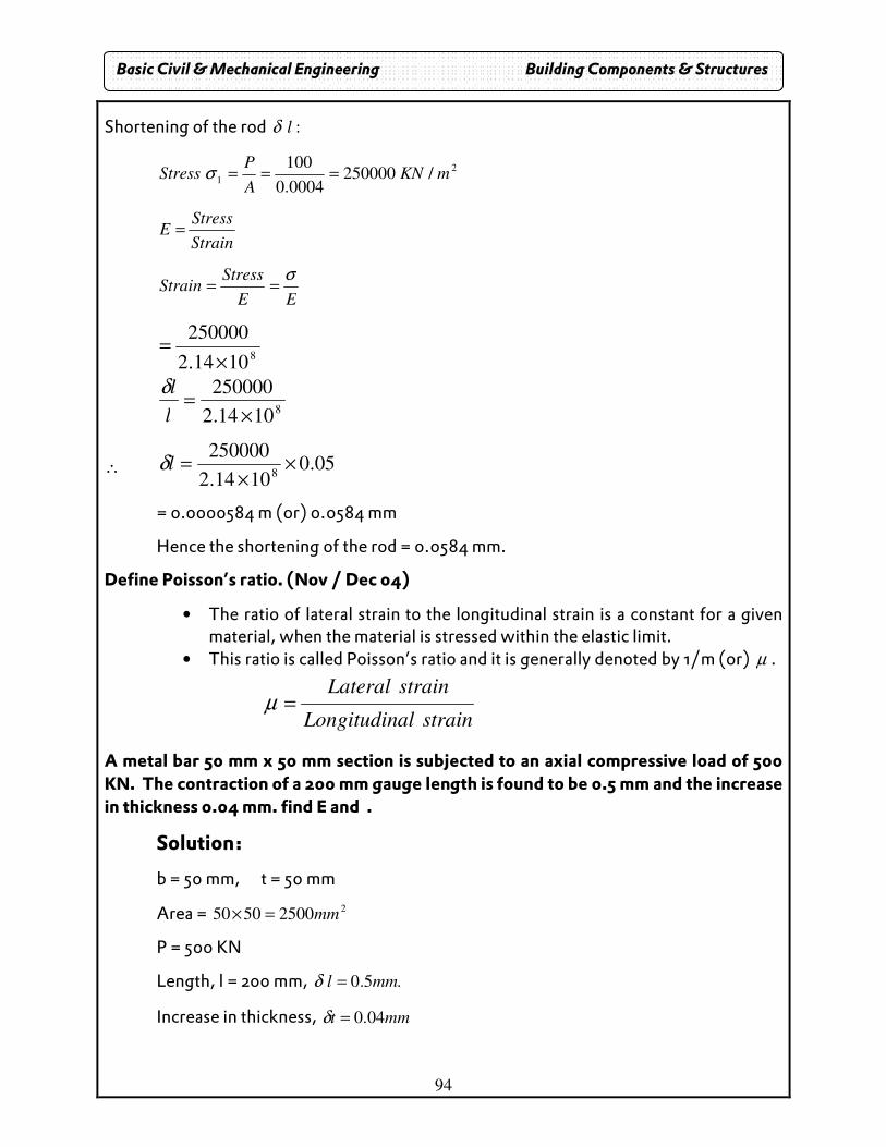
94
Shortening of the rod :lδ
2
1/250000
0004.0
100mKN
A
PStress ===σ
Strain
StressE =
EE
StressStrain
σ==
8
1014.2
250000
×=
8
1014.2
250000
×=
l
lδ
∴ 05.01014.2
250000
8×
×=lδ
= 0.0000584 m (or) 0.0584 mm
Hence the shortening of the rod = 0.0584 mm.
Define Poisson’s ratio. (Nov / Dec 04)
• The ratio of lateral strain to the longitudinal strain is a constant for a given material, when the material is stressed within the elastic limit.
• This ratio is called Poisson’s ratio and it is generally denoted by 1/m (or) µ .
strainalLongitudin
strainLateral=µ
A metal bar 50 mm x 50 mm section is subjected to an axial compressive load of 500 KN. The contraction of a 200 mm gauge length is found to be 0.5 mm and the increase in thickness 0.04 mm. find E and .
Solution:
b = 50 mm, t = 50 mm
Area = 225005050 mm=×
P = 500 KN
Length, l = 200 mm, .5.0 mml =δ
Increase in thickness, mmt 04.0=δ
Basic Civil & Mechanical Engineering Building Components & Structures
95
Young’s Modulus:
AE
pll =δ
2
3
/802500
200105005.0 mmKNE
E=⇒
×
××=
Poisson’s Ratio:
strainLinear
strainLateral=µ
Linear strain = 0.0025 thicknessstrainLateralt ×=δ
500025.01
04.0 ××=m
The following observations were made during a tensile test on a mild steel specimen 40 mm in diameter and 200 mm long. Elongation with 40 KN load (within limit of proportionality) 0304.0=lδ mm, yield load = 161 KN
Maximum load = 242 KN
Length of specimen at fracture = 249 mm. Determine:
v. Young’s Modulus of Elasticity
vi. Yield point stress
vii. Ultimate stress
viii. Percentage elongation.
32.01
=m
Basic Civil & Mechanical Engineering Building Components & Structures
96
Solution:
i. Young’s Modulus of Elasticity (E):
Stress, ( )
24
2
/1018.3
04.04
40mKN
A
P×===
πσ
Strain, 000152.0200
0304.0===
l
le
δ
000152.0
1018.34×
==Strain
StressE
81009.2 ×= KN / m2
(ii) Yield point stress:
Yield point stress area
loadpoYield int=
( )
24
2
/108.12
04.04
161mKN×==
π
(iii) Ultimate stress:
Maximum load Ultimate stress = Area
( )
24
2
/102.19
04.04
242mKN×==
π
(iv). Percentage elongation:
Length of specimen at fracture original length Percentage elongation = Original length
245.0200
200249=
−=
= 24.5 %
Basic Civil & Mechanical Engineering Building Components & Structures
97
A bar of 30 mm φ is subjected to a pull of 60 KN. The measured extension on gauge
length of 200 mm is 0.09 mm and the change in diameter is 0.0039 mm. Calculate µ
and the values of the three module.
Solution:
i. Young’s Modulus:
e
Eσ
=
( )
2
2
3
/9.84
304
1060mmN
A
P=
×==
πσ
00045.0200
09.0===
l
le
δ
2/67.188 mmKNE =
ii. Poisson’s ratio:
e
dd
strainLinear
strainLateral /δµ ==
00013.03
00039.0/ ==ddδ
13
45
45
13
00045.0
00013.0=⇒== mµ
iii. Modulus of rigidity:
( )2
3
/19.73
113
452
1067.18813
45
12mmKN
m
mEC =
+
××
=+
=
iv. Bulk Modulus:
( )2
3
/95.148
213
453
1067.18813
45
23mmKN
m
mEK =
−
××=
−=
Basic Civil & Mechanical Engineering Building Components & Structures
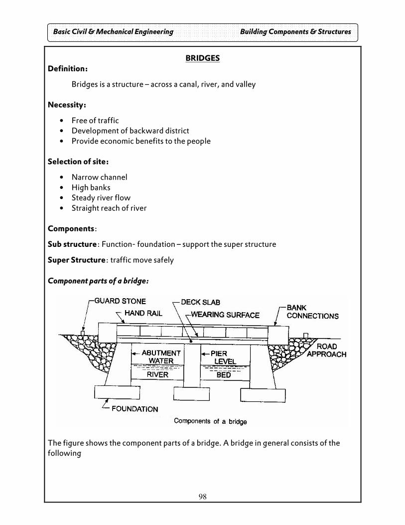
98
BRIDGES Definition:
Bridges is a structure – across a canal, river, and valley
Necessity:
• Free of traffic • Development of backward district • Provide economic benefits to the people
Selection of site:
• Narrow channel • High banks • Steady river flow • Straight reach of river
Components:
Sub structure: Function- foundation – support the super structure
Super Structure: traffic move safely
Component parts of a bridge:
The figure shows the component parts of a bridge. A bridge in general consists of the following
Basic Civil & Mechanical Engineering Building Components & Structures
99
Deck with road surface: Deck is the top horizontal portion of the bridge. The road way is formed on the deck. The deck may be made of R.C.C. or prestressed concrete or steel girders and joints. The deck is laid over the piers and abutments. Piers: The intermediate supports (columns) that transmit the load from the deck to the foundation below are called piers. The piers may be constructed of masonry, concrete or R.C.C... There may be one, two or more piers depending upon the length of the bridge and the span between the piers. Abutments: The two end supports of a bridge are called abutments. As piers, abutments also carry the vertical loads. In addition, they withstand the horizontal thrust developed and transmit the same to the soil. The bank connections like wing walls are constructed adjoining the abutments. Foundations: Foundations from the bottommost part of a bridge. The type of foundation adopted depends upon the nature of the subsoil and the magnitude of the load transmitted. Well foundation and piles are some types of bridge foundations adopted. Bank connections: Bank connections like wing walls and return walls provide a firm connection between the bridge abutments and the road embankment (approach). They also retain the embankment earth. They direct the water into the spans of the bridge. Road approach: Road approach is the form of embankment properly protected on the slopes by revetment. Hand rails: Hand rails are erected on the sides along the length of the bridge. They serve as guard for the users and prevent the possibility of any user falling by slip. Guard stones: Guard stones available on both sides indicate the presence of a bridge to the road users approaching the bridge at a distance. Further, they give an idea about the width of the bridge and guide the vehicles fro a safe entry into the bridge. River bed: is the top earth surface of the river. MFL is the maximum flood level for which the bridge is designed. Materials used: Bridges are constructed by using stone masonry, brick masonry, reinforced cement concrete, pre-cast concrete, prestressed concrete, iron and steel and timber.
Basic Civil & Mechanical Engineering Building Components & Structures
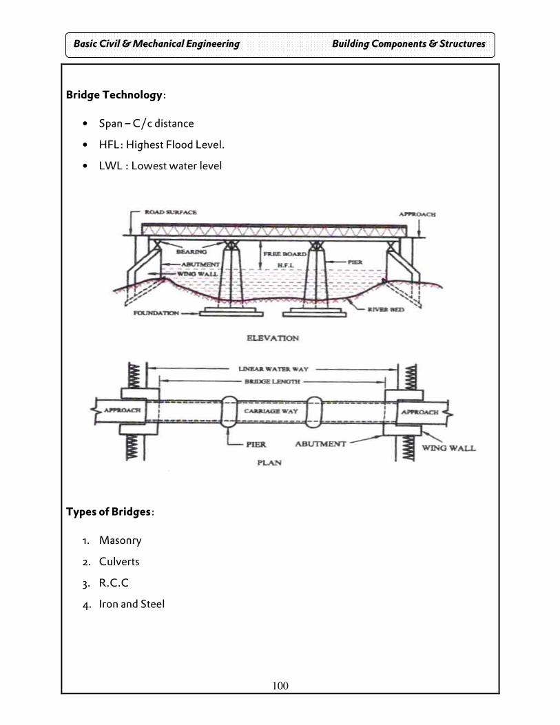
100
Bridge Technology:
• Span – C/c distance
• HFL: Highest Flood Level.
• LWL : Lowest water level
Types of Bridges:
1. Masonry
2. Culverts
3. R.C.C
4. Iron and Steel
Basic Civil & Mechanical Engineering Building Components & Structures
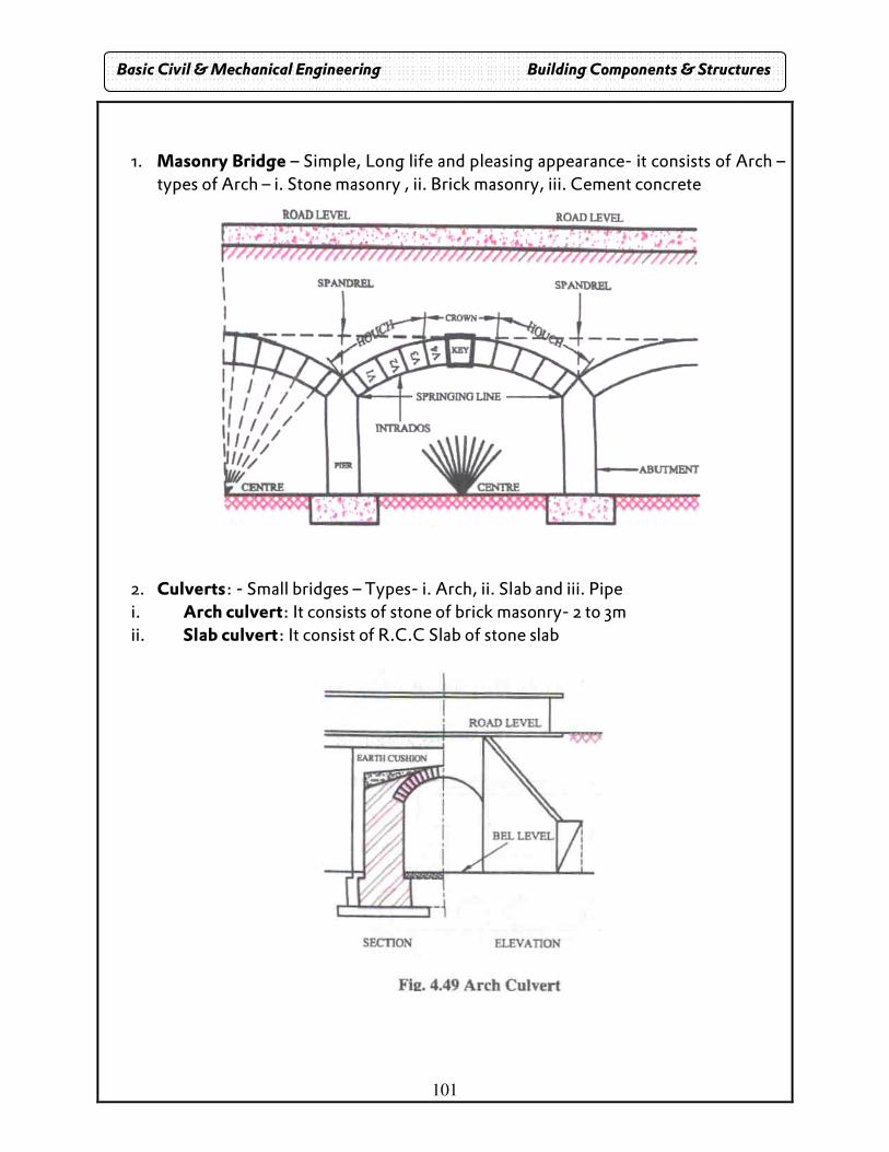
101
1. Masonry Bridge – Simple, Long life and pleasing appearance- it consists of Arch – types of Arch – i. Stone masonry , ii. Brick masonry, iii. Cement concrete
2. Culverts: - Small bridges – Types- i. Arch, ii. Slab and iii. Pipe i. Arch culvert: It consists of stone of brick masonry- 2 to 3m ii. Slab culvert: It consist of R.C.C Slab of stone slab
Basic Civil & Mechanical Engineering Building Components & Structures
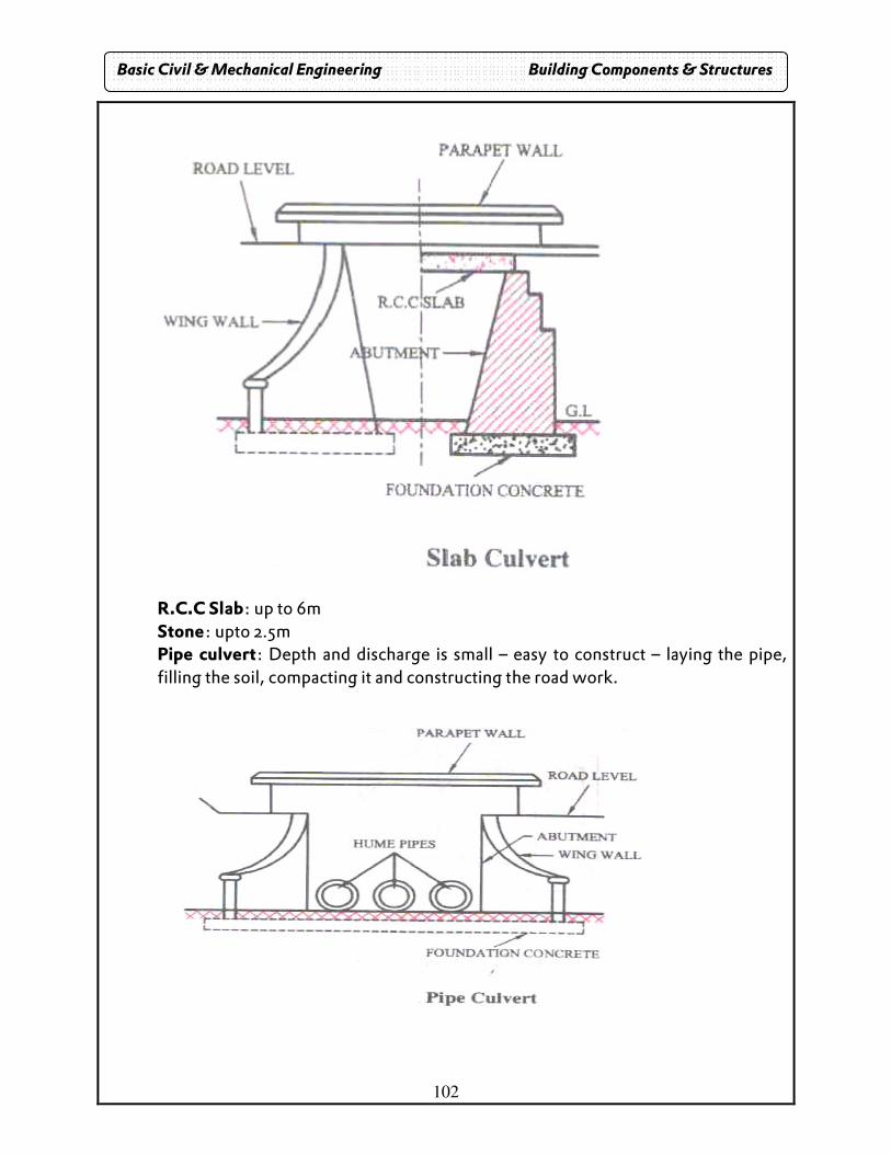
102
R.C.C Slab: up to 6m Stone: upto 2.5m Pipe culvert: Depth and discharge is small – easy to construct – laying the pipe, filling the soil, compacting it and constructing the road work.
Basic Civil & Mechanical Engineering Building Components & Structures
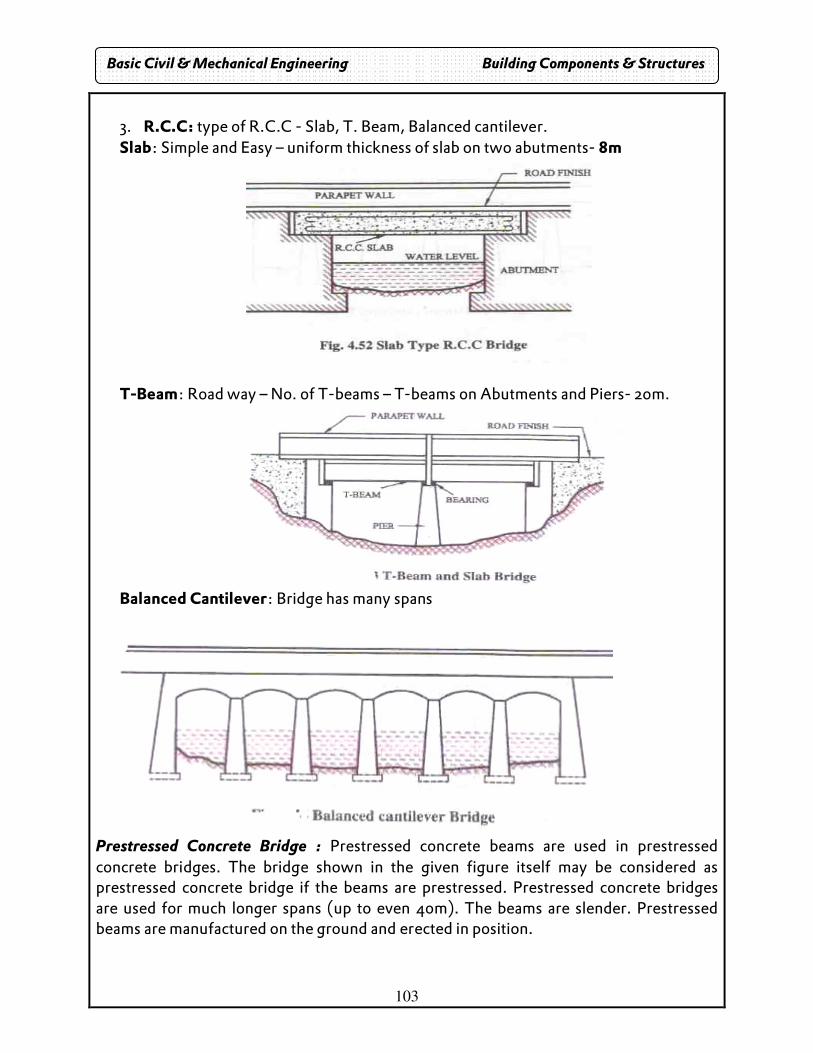
103
3. R.C.C: type of R.C.C - Slab, T. Beam, Balanced cantilever. Slab: Simple and Easy – uniform thickness of slab on two abutments- 8m
T-Beam: Road way – No. of T-beams – T-beams on Abutments and Piers- 20m.
Balanced Cantilever: Bridge has many spans
Prestressed Concrete Bridge : Prestressed concrete beams are used in prestressed concrete bridges. The bridge shown in the given figure itself may be considered as prestressed concrete bridge if the beams are prestressed. Prestressed concrete bridges are used for much longer spans (up to even 40m). The beams are slender. Prestressed beams are manufactured on the ground and erected in position.
Basic Civil & Mechanical Engineering Building Components & Structures
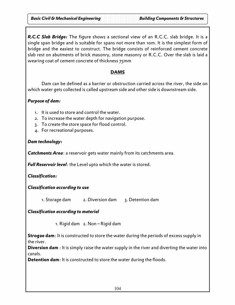
104
R.C.C Slab Bridge: The figure shows a sectional view of an R.C.C. slab bridge. It is a single span bridge and is suitable for spans not more than 10m. It is the simplest form of bridge and the easiest to construct. The bridge consists of reinforced cement concrete slab rest on abutments of brick masonry, stone masonry or R.C.C. Over the slab is laid a wearing coat of cement concrete of thickness 75mm
DAMS
Dam can be defined as a barrier or obstruction carried across the river, the side on which water gets collected is called upstream side and other side is downstream side.
Purpose of dam:
1. It is used to store and control the water. 2. To increase the water depth for navigation purpose. 3. To create the store space for flood control. 4. For recreational purposes.
Dam technology:
Catchments Area: a reservoir gets water mainly from its catchments area.
Full Reservoir level: the Level upto which the water is stored.
Classification:
Classification according to use 1. Storage dam 2. Diversion dam 3. Detention dam Classification according to material 1. Rigid dam 2. Non – Rigid dam Strogae dam: It is constructed to store the water during the periods of excess supply in the river. Diversion dam : It is simply raise the water supply in the river and diverting the water into canals. Detention dam: It is constructed to store the water during the floods.
Basic Civil & Mechanical Engineering Building Components & Structures
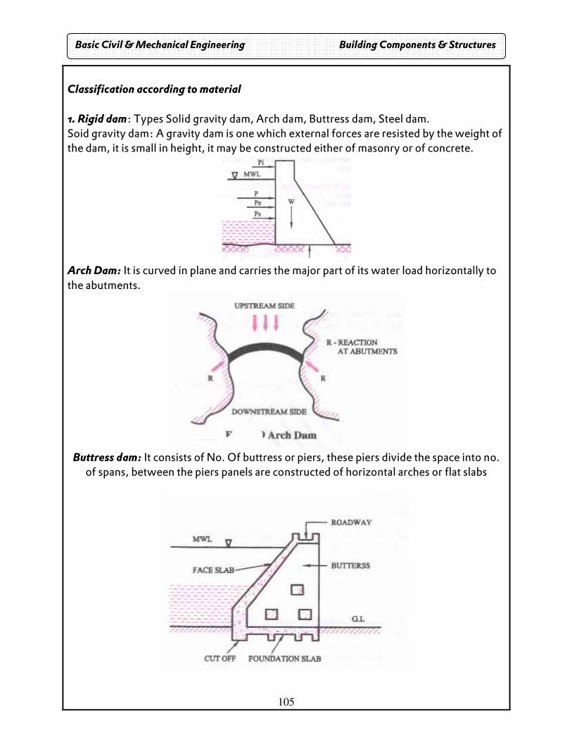
105
Classification according to material 1. Rigid dam: Types Solid gravity dam, Arch dam, Buttress dam, Steel dam. Soid gravity dam: A gravity dam is one which external forces are resisted by the weight of the dam, it is small in height, it may be constructed either of masonry or of concrete.
Arch Dam: It is curved in plane and carries the major part of its water load horizontally to the abutments.
Buttress dam: It consists of No. Of buttress or piers, these piers divide the space into no.
of spans, between the piers panels are constructed of horizontal arches or flat slabs
Basic Civil & Mechanical Engineering Building Components & Structures
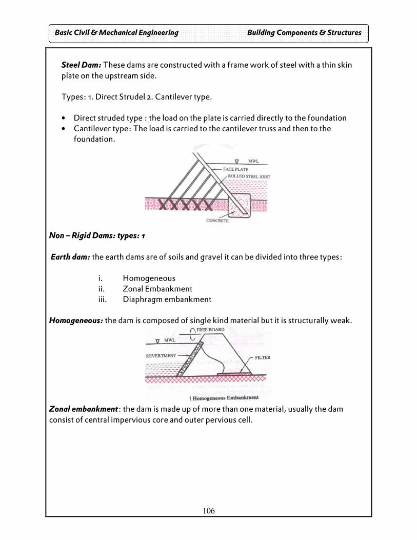
106
Steel Dam: These dams are constructed with a frame work of steel with a thin skin plate on the upstream side. Types: 1. Direct Strudel 2. Cantilever type. • Direct struded type : the load on the plate is carried directly to the foundation • Cantilever type: The load is carried to the cantilever truss and then to the
foundation.
Non – Rigid Dams: types: 1 Earth dam: the earth dams are of soils and gravel it can be divided into three types:
i. Homogeneous ii. Zonal Embankment iii. Diaphragm embankment
Homogeneous: the dam is composed of single kind material but it is structurally weak.
Zonal embankment: the dam is made up of more than one material, usually the dam consist of central impervious core and outer pervious cell.
Basic Civil & Mechanical Engineering Building Components & Structures
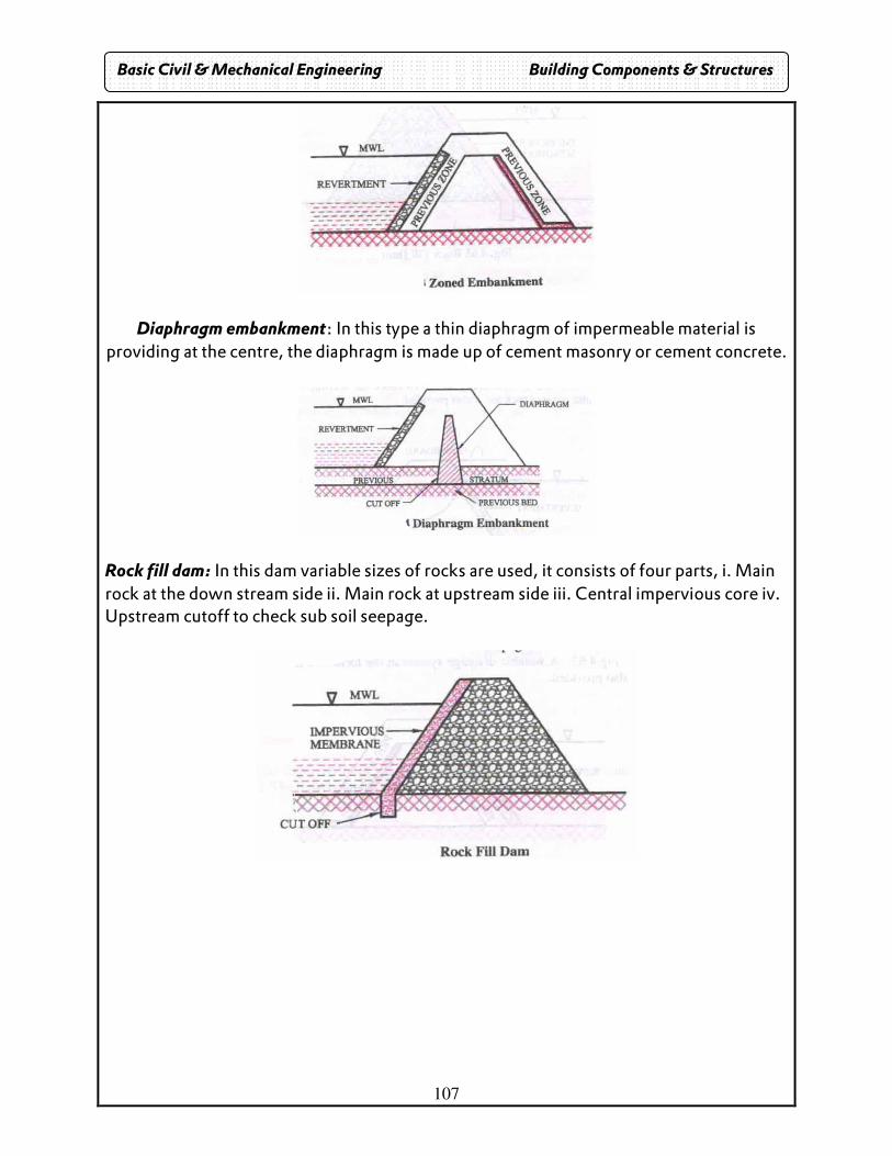
107
Diaphragm embankment: In this type a thin diaphragm of impermeable material is providing at the centre, the diaphragm is made up of cement masonry or cement concrete.
Rock fill dam: In this dam variable sizes of rocks are used, it consists of four parts, i. Main rock at the down stream side ii. Main rock at upstream side iii. Central impervious core iv. Upstream cutoff to check sub soil seepage.
Basic Civil & Mechanical Engineering Building Components & Structures
108
Two Mark Questions & Answers

109
110
UNIT I SURVEYING AND CIVIL ENGINEERING MATERIALS
1. Define Civil Engineering.
� Civil Engineering is the branch of engineering which aims to provide a comfortable and safe living for the people.
2. What are the major specializations of Civil Engineering?
� Structural engineering � Geotechnical Engineering � Fluid Mechanics, Hydraulics and Hydraulic machines � Transportation Engineering � Water supply, sanitary and environmental engineering � Irrigation Engineering � Surveying, leveling and remote sensing
3. What are the various functions of Civil Engineer?
� Investigation � Surveying � Planning � Design � Execution � Running and maintenance � Research and development
4. What are the classifications of Bricks?
� First class bricks � Second class bricks � Third class bricks � Over burnt (Fourth class) bricks
5. What are the constituents of bricks?
� Alumina – 20 to 30% � Silica – 50 – 60%to � Lime - Up to 5% � Oxide of iron – 5 or 6% � Magnesia
Basic Civil & Mechanical Engineering Two Mark Questions & Answers
111
6. What are the three types of classifications of rocks?
� Geological Classification � Physical Classification � Chemical Classification
7. How do you classify the rocks based on chemical classification?
� Siliceous rocks � Argillaceous rocks � Calcareous rocks
8. How do you classify the rocks based on the geological classification?
� Igneous rocks � Sedimentary rocks � Metamorphic rocks
9. How do you classify the rocks based on the physical classification?
� Stratified rocks � Un-Stratified rocks � Foliated
10. Write short notes on quarrying and dressing of stones?
� Quarrying: Stones are obtained from rocks by quarrying. Quarrying of stones is done at some depth below the top surface of rock where the effects of weathering are not found. Only the dense and good quality of stones can be obtained.
� Quarrying may be done with hand tools hand tools by the process of excavating, wedging or heating. Soft varieties of stones like lime stone and marble are quarried by using channeling machines. Dense and compact rocks are quarried by blasting. Different explosives are used for blasting of rocks.
� Dressing: Quarried stones may be used as they are or they may be crushed to
pieces. Quarried stones are dressed differently depending upon the types of stones and the nature of works for which they are used. The stones are dressed to have hammer-dressed surface, tooled surface, cut stone surface rubbed surface or polished surface.
Basic Civil & Mechanical Engineering Two Mark Questions & Answers
112
11. What are the various types of cement?
� Ordinary Portland cement � Rapid hardening cement � Sulphate resisting cement � Low heat cement � Quick setting cement � High alumina cement
11. Define mortar.
� The term mortar is used to indicate a paste prepared by adding required quantity of water to a mixture of binding material (cement or Lime) and fine aggregate.
12. What are the mortars used for plastering?
� Cement mortar, lime mortar or cement-lime mortar is used for plastering. 13. What are the materials used for preparing mortar?
� Cement mortar: Cement and sand. � Lime mortar: Lime (class B and C) and sand. � Cement-lime mortar: Cement, lime and sand.
14. What are the requirements for flooring?
The basic requirements of any flooring are,
� Strength and durability � Low cost of construction and maintenance � Good resistance to temperature and fire � Non-slipperiness � Good appearance
15. Define cement concrete.
� Cement concrete may be defined as a building material obtained by mixing cement, fine and course aggregate (crushed rock) and water in suitable proportions.
Basic Civil & Mechanical Engineering Two Mark Questions & Answers
113
16. What are the various types of concretes?
� Light weight concrete � High density concrete � Polymer concrete � Fiber reinforced concrete
17. How do you classify the steel according to its carbon content?
� Low carbon steel 0.1 - to 0.25% � Medium carbon steel – 0.25 to 0.7% � High carbon steel – 0.7 to 1.5%
18. Define foundation
� Foundation or substructure is the lower portion of the building, usually located below the ground level, which transmits the load of super structure to the supporting soil.
19. Specify the objective s of foundation.
� To distribute the load coming on the structure on a larger area. � To support the load � To prepare a level surface for concreting and masonry work.
� Define the bearing capacity of soil.
� This term is used to indicate the maximum load per unit area, which the soil will
resist safely without displacement. Ultimate bearing capacity of soil
� Safe bearing capacity of the soil = Factor of safety 20. Define ultimate bearing capacity of soil.
� It is defined as gross pressure intensity (maximum load on the soil per unit area) at the base of the foundation at which the soils fails by shear.
21. What are the three types of loads borne by foundation?
� Dead load Live load Wind load
Basic Civil & Mechanical Engineering Two Mark Questions & Answers
114
22. What are the essential requirements of good foundation?
� The foundation should be, so located that it is able to resist any unexpected future influence, which may adversely affect its performance.
� The foundation should be stable or safe against any possible failure. � The foundation should not be settle or defect to such an extent that will impair its
usefulness. 23. What are the types of foundations?
� Shallow foundation � Isolated footing � Combined footing � Strip footing – 1. Simple footing 2. Stepped footing
24. Deep foundation
� Pile foundation � Under-reamed piles.
25. Define surveying and explain the basic principle.
� Surveying is the science of large scale geometrical measurement on the earth – surface to establish the position and size or is the art of science to determine the relative position on the surface of the earth or below the earth.
� Principle: Location of point from two basic points working from the whole part. 26. What are the classifications of survey?
� Depending up on the location or field survey. � Depending up on the objects. � Depending up on the methods. � Depending up on the instruments used.
27. What is the basic principle of chain surveying? And list out the instruments used in chain surveying.
� The principle of chain surveying is dividing the area into no of triangles. � Instruments used: Chain, Tape, Arrow, Pegs, Ranging rods, offset rods, plumb bob
and Cross staff.
Basic Civil & Mechanical Engineering Two Mark Questions & Answers
115
28. What are the types of bearing?
� Magnetic bearing: The angle between any line and magnetic meridian. � True bearing: The bearing between any line and geographic meridian.
29. Define leveling.
� Leveling may be defined as the art of determining the relative height or elevations of points on earth surface.
30. List out advantages and disadvantages of chain surveying.
� Advantages:
� It is simple � Less cost � It is accuracy for small area.
� Disadvantages:
� Less accuracy � It is not used for larger area.
31. Write down the geological classification of rocks.
� Igneous rocks: Granite, Basalt � Sedimentary rocks: Gravel, Lime stone � Metamorphic rocks: Marble.
32. What is mean by natural bed of stone?
� Rocks have distinct plane of division along which stone can be easily split. 33. What are the good qualities of stone?
� Percentages of absorption of water not exceed 0.6%. � It should be uniform in colour.
34. Write down the standard size of brick.
� Size: (19 X 9 X 9) cm, Weight: 3 to 3.5 kg.
Basic Civil & Mechanical Engineering Two Mark Questions & Answers
116
35. Write down the composition of good brick.
� Alumina – 20 to 30%, Silica – 50 to 60%, Lime 3 to 5%, Magnesia 2 to 3%, Oxide of iron 5 to 6%
36. What are the tests conducted for bricks?
� Water absorption test, Crushing strength test, Soundness test. 37. What are the main constituents of cements?
� Argillaceous (Lime stone and silica), Calcareous (Clay and gypsum). 38. Write any two properties of cement.
� Excellent binding system, good resisting to moisture. 39. What is the function of gypsum and chromium oxide?
� Gypsum: Slows the setting time of cement. � Chromium oxide: It gives green colour to cement.
40. What are the tests for fresh concrete?
� Slum test, Compact factor test. 41. What is the purpose of curing?
� It reduces the drying, Shrinkage and promotes the hydration. 42. What are the properties of concrete?
� High compressive strength reduces the abrasion. 43. What is mean by M15 concrete?
� M – Mix, 15 – Characteristic strength of 15cm3. 4. What is the percentage of carbon content in the cast iron and mild steel?
� Cast iron: - 2 to 4% Mild steel: 0.1 to 0.25%
Basic Civil & Mechanical Engineering Two Mark Questions & Answers
117
UNIT II BUILDING COMPONENTS AND STRUCTURES 1. Define super structure.
� Super structure consists of maximum of walls, doors, window sand lintels. The purpose of super structure is to provide the necessary utility of the building, structural safety, fire safety, sanitation and ventilation.
2. Define header course.
� This is the brick laid with its breath or width parallel to the face or direction of the wall. A course containing is a header course.
3. Define stretcher course.
� This is the brick laid with its length parallel to the face or direction of a wall. A layer of bricks containing stretcher is called stretcher course.
4. Define Bond.
� It is an arrangement of stones or bricks, such that no continuous vertical joints are formed.
5. Define Lap.
� The horizontal distance between the vertical joints in two successive courses is termed as lap.
6. Define Queen closer.
� This is obtained by cutting the brick longitudinally into two equal parts. This is generally placed near the quoin header to obtain necessary lap.
7. Define king closer.
� This is obtained by cutting a triangular portion of the brick such that half a header and half stretcher are obtained on the adjoining cut faces.
8. Define Bat.
� It is the portion of the brick cut across the width. Thus a bat is smaller in length than the full bricks. If the length of the brick is equal to half the length of the original brick, it is known as half bat.
Basic Civil & Mechanical Engineering Two Mark Questions & Answers
118
9. What are the various types of bond in brick work?
� Stretcher bond � Header bond � Flemish bond � English bond.
10. Define masonry.
� Masonry may be defined as the construction building units bonded together with mortar.
11. Define brick masonry.
� Brick masonry is made of brick units bonded together with mortar. Two essential components of brick masonry are:
� Brick � Mortar
12. Define stone masonry
� Stone masonry is made of stone units bonded together with mortar. 13. Define corbel
� A corbel is a projecting stone which is usually provided to serve as a support for roof truss, beam, weather shed, etc.
14. What are the classifications of stone masonry?
� Rubble masonry � Coursed rubble masonry � Uncoursed rubble masonry � Random rubble masonry
� Ashlar masonry. 15. Define Beam.
� Beams are structural members that can carry transverse loads, which produce bending moments and shear. Beams may be horizontal or sloping.
Basic Civil & Mechanical Engineering Two Mark Questions & Answers
119
16. Define Column.
� Columns are structural elements used primarily to support compressive loads. They may be constructed of timber, stone or brick masonry, reinforced cement concrete or steel section.
17. Define lintel
� A lintel is a horizontal member, which is placed across an opening to support the portion of the structure above it. The width of the lintel is equal to the width of the wall.
18. What are the various types of lintels?
� Wood lintel � Stone lintel � Brick lintel � Steel lintel � Reinforced cement concrete lintel
19. Define roofing
� A roof is the uppermost part of a building which is supported on structural members and covered with roofing materials to give protection to the building against rain, wind, heat, snow, etc.
20. Define steel truss.
� Truss is a pin jointed frame of axially located members. Steel trusses are used for pitched roofs especially in industrial buildings. Steel trusses are normally adopted for spans greater than 12m.
21. List out some of the roof coverings for pitched roof?
� Thatch roofing � Half round tiles � Shingles � Patent tiles
Basic Civil & Mechanical Engineering Two Mark Questions & Answers
120
22. Define weather proof course.
� Weather proof course is also known as weathering course. Weathering course is a layer provided on the top of R.C.C or Madras terrace roof to protect the roof from the weathering agencies like rain, wind, sun, and snow.
23. Define flooring.
� Floors are the elements of building structure, which divide the building into different levels for the purpose of creating more accommodation within a limited space.
24. What are the two components of flooring?
� A sub floor � Floor covering
25. What are factors considered in selection of flooring?
� Initial cost � Cleanliness � Damp resistance � Thermal insulation � Fire resistance
26. What are the different materials used for flooring?
� Mud � Stones � Bricks � Concrete � Mosaic
27. What are the various types of flooring?
� Concrete flooring � Mosaic flooring � Terrazzo flooring � Tiled flooring
Basic Civil & Mechanical Engineering Two Mark Questions & Answers
121
28. Define damp proofing
� Damp proofing is the method adopted to prevent the entry of dampness into a building, so as to keep them dry, habitable and safe.
29. Define plastering.
� Plastering is a process of covering rough walls and uneven surfaces in the construction of houses and other structures with a plastic material called plaster or mortar.
30. What are the objectives of plastering?
� To provide an even, smooth, regular, clean and durable finished surface and hence to improve the appearance
� To protect the surfaces from the effects of atmospheric agencies. � TO connect the effective workmanship.
31. What are the four types of plasters?
� Lime plaster � Cement plaster � Mud plaster � Water proof plaster
32. Define valuation.
� Valuation is the technique of estimating or determining the fair price or value of property such as a building, a factory, other engineering structures of various types, land, etc.
33. What are the various methods used for valuation of building?
� Rental method of valuation � Direct comparison with capitalized value � Valuation based on profit � Valuation based on loss.
Basic Civil & Mechanical Engineering Two Mark Questions & Answers
122
34. Define the following terms.
� Stress: The load resisting per unit area is termed as stress. The unit is N/mm2. � Strain: The ratio between changes in dimension to its original dimension. � Linear strain: The ratio between change in length its original length
� = Change in length/Original length = ∂l/L � Lateral strain: Change in diameter/Original diameter = ∂d/D � Hooks Law: Within the elastic limit stress is directly proportional to the strain
� E = Stress/Strain. N/mm2 � Young’s Modulus:
� E = Stress/Strain. N/mm2 � Bulk Modulus:
� K = Direct stress/Volumetric strain = σ/ev in N/mm2 � Shear stress = Shear stress/Shear strain � Poison’s Ratio (µ) = 1/m = Lateral strain/Longitudinal or linear strain.
35. Write the relationship three modules
� E = 2C (1+1/m), E = 3K (1-2m), E = 9KC/3K + C. 36. Define factor of safety.
� It is the ratio between the ultimate stress to the working stress. � FOS = Ultimate stress/Working stress.
37. What is mean by lintel and where it is used?
� Small size beam provided at the top of the door opening is called lintel. Lintel acts like a beam and transverse the load vertically to supporting walls.
38. What is the difference between beams and columns?
� Beam: It is a horizontal structural member � Column: It is vertical structural member
39. How do you differentiate long and short column?
� Long column: L/D ≥ 12m � Short column: L/D ≤ 12m
Basic Civil & Mechanical Engineering Two Mark Questions & Answers
123
40. What is meant by dead load and live load?
� Dead Load: Self weight of various components � Live Load: super imposed load on structure.
41. Define foundation, Basement, super structure.
� Foundation: The portion of the building which comes below the building (sub structure).
� Objective of Foundation: To spread the load over the larger area and ensure the safety.
� Basement: The portion of the building between Ground level and plinth level � Super structure: The portion of the building which comes plinth and roof level.
42. What are the types of foundation?
� Shallow Foundation: It is opted for light structure, soils have high bearing capacity (B/D<2).
� Deep Foundation: It is opted for heavy structure, soils have low bearing capacity (B/D>2).
43. What is mean by pile foundation and explain the types of piles?
� Pile foundation is used if the soil is loose and the structure is tall and heavy. � Types of pile: End bearing pile and friction pile.
44. What is mean by machine foundation?
� Foundation for machine is designed to make entire arrangement safe during operation. Concrete is for machine foundation M15. E.g.: Reciprocating machine, Impact machine.
45. What is mean by flooring and what are the requirements?
� Flooring is the horizontal area in any floor of the area. � Requirements: Low cost, Good appearance, Sound and thermal insulation,
smoothness. � Materials used for flooring: Mud, Tiles, Stone, Bricks, Granite, Marble, Concrete.
Basic Civil & Mechanical Engineering Two Mark Questions & Answers
124
46. Define roof and what are the requirements?
A roof is the upper most part of the building which is supported on the structural members and covered with roofing material.
Requirements: Water proof, Dust proof and exclude sun’s heat. It should be made up of durable material, it should present a pleasing appearance, good ventilation.
47. Define Ridge and Eaves.
� Ridge: Apex of inclined roof. � Eaves: Lower edge of inclined roof.
49. What are the purposes of valuation?
� To fix the municipal tax of the property, for sale of property. 50. Compare the trapezoidal and Simpson’s rule.
� Trapezoidal rule: Area computed is approximate. Boundary between the ordinate is sight.
� Simpson’s rule: Area computed is accurate. Boundary between the ordinate is parabola.
51. What is the use of culvert?
� Culvert is the small bridge span up to 6m. 52. What is the carriage way, catchments area, run off?
� Carriage way: Minimum linear distance between the edges of surface. � Catchment area: It is the area which contributed surplus water present. � Run off: Freely flowing rain water.
53. Give the example of storage and diversion dam.
� Storage dam: Mettur dam, Sathanoor dam. � Diversion dam: Grand anaicut (Kallanai dam)
Basic Civil & Mechanical Engineering Two Mark Questions & Answers
125
54. Write down the components of reservoir.
� Pool of water on the upstream side. � Spill way � Irrigation canals
Question Bank
1. List the four operations involved in the manufacturing of a brick 2. What is the difference between a plan and a map? 3. State the principles of surveying. 4. What is quarrying & dressing of stones? 5. Difference between shallow foundation and deep foundation 6. Compare stone masonry and Brick masonry. 7. Comment on column and lintel 8. State the purpose of plastering 9. Classify the types of column based on its conditions. 10. List the basic components of a bridge. 11. Define surveying. 12. State the objects of surveying. 13. State the types of surveying. 14. What are the principles of surveying
Basic Civil & Mechanical Engineering Two Mark Questions & Answers
126
Mechanical Engineering

127
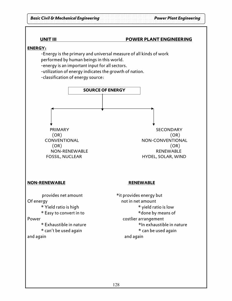
128
UNIT III POWER PLANT ENGINEERING
ENERGY: -Energy is the primary and universal measure of all kinds of work performed by human beings in this world.
-energy is an important input for all sectors. -utilization of energy indicates the growth of nation. -classification of energy source:
SOURCE OF ENERGY
PRIMARY SECONDARY (OR) (OR)
CONVENTIONAL NON-CONVENTIONAL (OR) (OR)
NON-RENEWABLE RENEWABLE FOSSIL, NUCLEAR HYDEL, SOLAR, WIND
NON-RENEWABLE RENEWABLE
provides net amount *it provides energy but
Of energy not in net amount * Yield ratio is high * yield ratio is low * Easy to convert in to *done by means of
Power costlier arrangement * Exhaustible in nature *In exhaustible in nature * can’t be used again * can be used again
and again and again
Basic Civil & Mechanical Engineering Power Plant Engineering
129
TYPES OF ENERGY: Energy from water � Hydel energy
Energy from sun � solar energy Energy from wind � wind energy Energy from tides � tidal energy Energy from earth’s core � geothermal energy
SOURCES OF ENERGY:
(i) fossil fuels (ii) energy stored in water (iii) nuclear energy (iv) geo-thermal energy
1. FOSSIL FUELS:
SOLID FUELS: Naturally occurring solid fuels include wood, coal, lignite (brown coal). LIQUID FUELS: petroleum, diesel GASEOUS FUELS: Natural gas from petroleum wells.
Fossil fuels � coal 60% of total coal � eastern BIHAR & WEST BENGAL
N.L.C. � 900 MW, ENNORE � 450 MW 2. ENERGY FROM H20:
Potential energy of water at high level used for electrical power IN 100%
60% � Himalayan Brahmaputra, INDUS, GANGES 15% � CENTRAL INDIA (Narmada, Tapti, Mahanadi) 15% � SOUTHERN INDIA (Kaveri, Krishna, Godavari)
3. NUCLEAR ENERGY:
Small amount of fuel � great energy 1 kg U235 � 4500 tonnes of high grade coal U235 � Bihar, Rajasthan, Chennai. Disposal of U235 + 0N1 � Ba + Kr Kalpakkam � IGCAR
4. SOLAR ENERGY: The heat energy contained in rays of sun.
SUN � EARTH (3.7 X 10²⁰ )MW (1.8 X 10¹¹ )MW IIT � BOMBAY BHEL � HYDERABAD
Basic Civil & Mechanical Engineering Power Plant Engineering
130
5. WIND ENERGY: Using wind at suitable velocity. Used in south TAMIL NADU
6. TIDAL ENERGY: Using potential energy of tides P = ½(ρAV3) Requires minimum height & site: Gulf of Kutch
7. GEO-THERMAL ENERGY:
Thermal energy naturally available in the form of steam in some in some part of the earth under earth surface -2020 The exhausting of fossil fuel
R&D: Renewable energy � solar & wind
Basic Civil & Mechanical Engineering Power Plant Engineering
131
THERMAL POWER PLANT
INTRODUCTION:
• Coal and air are the fuel in steam power plant. • Coal gets oxidized and release large amount of energy. • This energy is transferred to H2O and it is converted into high pressure
steam. • This pressure steam is made to undergo expansion and it produces
mechanical works which is referred to as torque.
ESSENTIAL PARTS:
• Coal and ash circuit • Air and flue gas circuit • Feed water and stream circuit • Cooling water circuit
COAL AND ASH CIRCUIT: • Coal is then transported to the coal mine yard through logistics. Here coal is
stored and drawn when needed. • Then it is carried by conveyors to coal preparation center. • Here coal is pulverized in order to increase its surface area. This promotes
rapid combustion. • The product by combustion (flue gas) transfers the heat to boiler. • After that it passes to chimney through air pre heater. • Ash resulting from combustion of coal in the boiler furnace collects at the
back of boiler and • It is removed to ash storage ash disposal. The Indian coal contains 30 to 40 %
ash. • Power plant of 100MW produces 20 to25 tonnes of hot ash per hour. • Sufficient space near power plant is essential to dispose such large quantity
of ash.
AIR AND FLUE GAS: • Air is taken from atmosphere. • Air is heated in air pre heater by the heat of flue gas which is passing to
chimney. • The hot air is supplied to the boiler. • The flue gases after combustion in the furnace pass around the boiler tubes.
The flue gas then passes through dust collector. Economizer and pre heater before being exhausted
Basic Civil & Mechanical Engineering Power Plant Engineering
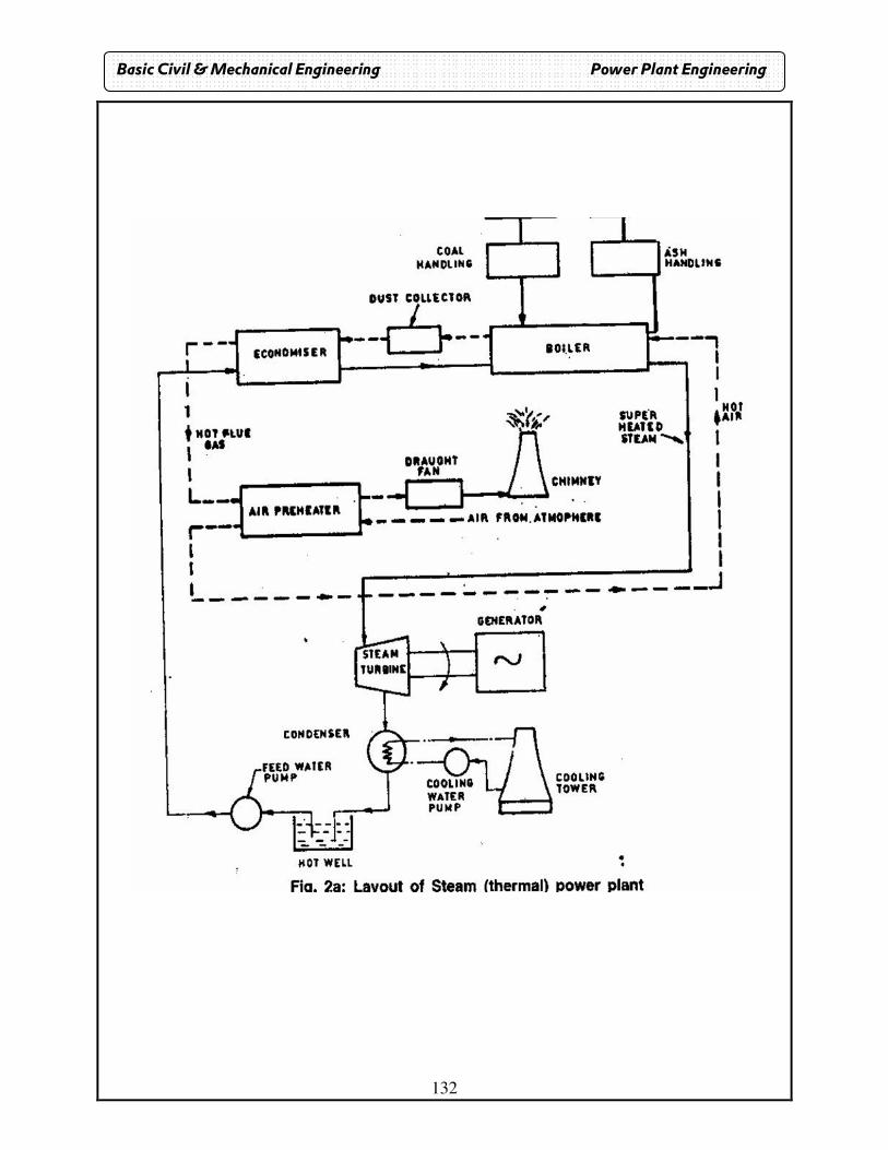
132
Basic Civil & Mechanical Engineering Power Plant Engineering
133
FEEDWATER AND STREAM CIRCUIT: • The feed water is pumped to boil by using the feed pumps. The feed water
enters economizer.
• Where it is preheated by the flue gas.
• It saves the fuel consumption.
• Then it enters into the boiler where it is converted into high pressure steam.
• This super heated steam drives the turbine coupled to the generator to
produce electricity.
• The steam coming out of the turbine is of energy lost state and is condensed
in the condenser and again sent to feed water pump.
COOLING WATER CIRCUIT: • Cold water is used for condensing steam in the condenser.
• The coolant on absorbing passes on to top of a cooling tower from where it
is sprayed through nozzles.
• It is cooled by the cold air entering along the periphery of the cooling tower
from the bottom and traveling in upward direction.
• The hot coolant giving up its heat to air becomes cool and gets collected at
bottom of tower.
• The cold water is once again circulated by the coolant pump to condenser.
• Water required for condensing the steam may be taken from the sources.
ADVANTAGES: • Initial cost is low.
• Erection and commissioning less tones
DISADVANTAGES: • Non renewable source
• If the plant is away from coal mine the transportation is difficult
• Causes air pollution
• Life of thermal plant is less than hydro plant.
Basic Civil & Mechanical Engineering Power Plant Engineering
134
HYDRO POWER PLANT
INTRODUCTION: Hydro means water. This power plant utilizes the potential energy of water stored in dam built across the river. The potential energy of water is used to run the water turbine to which electric generator is coupled. This mechanical energy is converted into electric energy by means of generator.
COMPONENTS: WATER RESERVIOR: Availability- stored- headrace.
- Continuous availability of water is the basic necessity of plant. - Water collected from catchment area and stored in dam. - The level of water in the reservoir is called head race level.
DAM: - The function of dam is to increase the height of water level which
increases the reservoir capacity. - This height is known as working head.
SPILL WAY: Water after a certain level in the reservoir flows through the spillway and keep the level of water is maintained constant. PRESSURE TUNNEL: It carries water from reservoir to surge tank.
SURGE TANK: There is sudden increases pressure in the penstock due to sudden back flow of water as the load on the turbine is reduced. This sudden rise of pressure in the penstock is known as water hammer. The surge tank is introduced between the dam and power house to reduce the pressure in the penstock otherwise the penstock will be damaged. It also acts as supply tank when load on turbine is accelerated and acts as storage tank when load on turbine is decelerated.
WATER TURBINE: -The common prime movers are pelton wheel, Francis and Kaplan Pelton wheel- >70m high head Francis - 15-70m medium level Kaplan - <15 low head -The potential energy of water is converted into mechanical energy.
DRAFT TUBE: The water level to the tail race through draft tube which is connected to outlet of turbine.
Basic Civil & Mechanical Engineering Power Plant Engineering
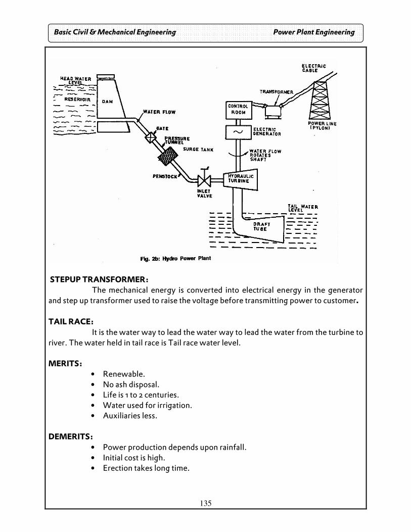
135
STEPUP TRANSFORMER: The mechanical energy is converted into electrical energy in the generator and step up transformer used to raise the voltage before transmitting power to customer. TAIL RACE: It is the water way to lead the water way to lead the water from the turbine to river. The water held in tail race is Tail race water level. MERITS:
• Renewable. • No ash disposal. • Life is 1 to 2 centuries. • Water used for irrigation. • Auxiliaries less.
DEMERITS:
• Power production depends upon rainfall. • Initial cost is high. • Erection takes long time.
Basic Civil & Mechanical Engineering Power Plant Engineering
136
NUCLEAR POWER PLANT
Basic principle:
• Nuclear power plant differs from conventional steam power plant only in steam generating part.
• There is no change in the turbo-alternator and the condensing system.
• The nuclear fuel which is present in commercial use is uranium. Scientists say that 1 kg of U235 Produce as much energy as can be produced by burning 2500 tonnes of high grade coal.
• Uranium exists in the isotopic form of U235 which is unstable. When a neutron enters the nucleus of U235 , the nucleus splits in to two equal fragments and also releases 2.5 fast moving neutrons with a velocity of 1.5 X 10 ^ 7 meters/sec producing a large amount of energy , nearly 200 millions electro-volts. This is called “nuclear fission”.
Chain reaction:
• The neutrons released during the fission can be made to fission with other nuclei of U235 causing a chain reaction.
• A chain reaction produces enormous amount of heat, which is used to produce steam.
• The chain reaction under controlled conditions can produce extremely large amount of energy causing atomic explosion.
• Energy liberated in chain reaction is according to Einstein law, is E=MV2 where
M= mass in grams, E=energy liberated, V= speed of light=3x10^10 cm/sec Out of 2.5 neutrons released in fission of each nuclei of U235, one neutron is used to sustain the chain reaction, 0.9 neutron is used to converted into fissionable material PU239 and 0.6 neutron is absorbed by control rod and coolant moderator.
• Function of moderator is to reduce the energy of neutrons evolved during fission in order to maintain the chain reaction.
• The moderators which are commonly used are ordinary water and heavy water.
Basic Civil & Mechanical Engineering Power Plant Engineering
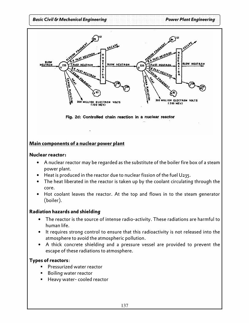
137
Main components of a nuclear power plant
Nuclear reactor:
• A nuclear reactor may be regarded as the substitute of the boiler fire box of a steam power plant.
• Heat is produced in the reactor due to nuclear fission of the fuel U235. • The heat liberated in the reactor is taken up by the coolant circulating through the
core. • Hot coolant leaves the reactor. At the top and flows in to the steam generator
(boiler).
Radiation hazards and shielding
• The reactor is the source of intense radio-activity. These radiations are harmful to human life.
• It requires strong control to ensure that this radioactivity is not released into the atmosphere to avoid the atmospheric pollution.
• A thick concrete shielding and a pressure vessel are provided to prevent the escape of these radiations to atmosphere.
Types of reactors: � Pressurized water reactor � Boiling water reactor � Heavy water- cooled reactor
Basic Civil & Mechanical Engineering Power Plant Engineering
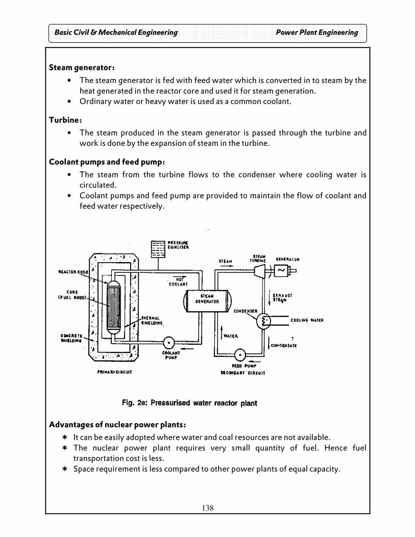
138
Steam generator:
• The steam generator is fed with feed water which is converted in to steam by the heat generated in the reactor core and used it for steam generation.
• Ordinary water or heavy water is used as a common coolant.
Turbine:
• The steam produced in the steam generator is passed through the turbine and work is done by the expansion of steam in the turbine.
Coolant pumps and feed pump:
• The steam from the turbine flows to the condenser where cooling water is circulated.
• Coolant pumps and feed pump are provided to maintain the flow of coolant and feed water respectively.
Advantages of nuclear power plants:
� It can be easily adopted where water and coal resources are not available. � The nuclear power plant requires very small quantity of fuel. Hence fuel
transportation cost is less. � Space requirement is less compared to other power plants of equal capacity.
Basic Civil & Mechanical Engineering Power Plant Engineering
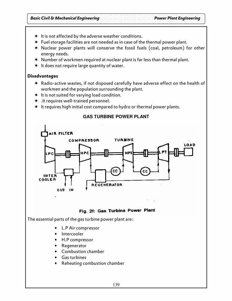
139
� It is not affected by the adverse weather conditions. � Fuel storage facilities are not needed as in case of the thermal power plant. � Nuclear power plants will conserve the fossil fuels (coal, petroleum) for other
energy needs. � Number of workmen required at nuclear plant is far less than thermal plant. � It does not require large quantity of water.
Disadvantages
� Radio-active wastes, if not disposed carefully have adverse effect on the health of workmen and the population surrounding the plant.
� It is not suited for varying load condition. � .It requires well-trained personnel. � It requires high initial cost compared to hydro or thermal power plants.
GAS TURBINE POWER PLANT
The essential parts of the gas turbine power plant are:
• L.P Air compressor • Intercooler • H.P compressor • Regenerator • Combustion chamber • Gas turbines • Reheating combustion chamber
Basic Civil & Mechanical Engineering Power Plant Engineering
140
L.P AIR COMPRESSOR: Atmospheric air is drawn in and passed through the air filter. It then flows in to the low pressure compressor. Major percentage of power developed (66%) by the turbine is used to run the compressor. The power required to run the compressor can be reduced by compressing the air in two stages, i.e., in low pressure and high pressure compressors and also by incorporating an intercooler between the two.
INTERCOOLER: Intercooler is used to reduce the work of the compressor and increase the efficiency. The energy required to compress air is proportional to the air temperature at inlet. Therefore if intercooling is carried out between the stages of compression, total work can be reduced.
H.P COMPRESSOR: From the intercooler, the compressed air enters the high pressure compressor, where it is further compressed to a high pressure. Then it is passed into the regenerator.
REGENERATOR: In the simple open cycle system the heat of the turbine exhaust gases goes as waste. To make use of this heat a regenerator is used. COMBUSTION CHAMBER: Hot air from regenerator flows to the combustion chamber. Fuel (natural or coal gas kerosene) is injected into the combustion chamber and burns in the stream of hot air. The products of combustion, comprising a mixture of gases at high temperature and pressure are passed to the turbine. GAS TURBINES: Products of combustion are expanded in high pressure turbine and then in low pressure turbine. The part of the work developed by the gases passing through the turbines is used to run the compressor and the remaining (about 34%) is used to generate electric power. Open cycle and closed cycle systems: When the heat is given to the air by mixing and burning the fuel in the air and the gases coming out of the turbine are exhausted to the atmosphere, the cycle is known as “open cycle system”. If the heat to the working medium (air or any other suitable gas) is given without directly burning the fuel in the air and the same working medium is used again and again, the cycle is known as “closed cycle system”. REHEATING COMBUSTION CHAMBER: The output of the plant can be further improved by providing a reheating combustion chamber between high pressure and low pressure turbines. In this, fuel is added to reheat the exhaust gases of high pressure turbine. The addition of the regenerator, intercooler and reheating combustion chamber increases the overall efficiency of the plant.
Basic Civil & Mechanical Engineering Power Plant Engineering
141
Operation of gas turbine power plant
The following are the steps of operation of gas turbine power plant. Refer to the layout of gas turbine power plant.
� First, atmospheric air is passed through the air filter. � The purified air is passed to the low-pressure compressor (LPC). Here the air is
compressed to a certain extent. � Now the air is passed to the intercooler. The temperature of outlet air from LPC
is reduced in inter cooler. � After this, the air is passed to the high-pressure compressor (HPC). Here the air
is again compressed to high pressure. � Now the air is passed through the regenerator where it absorbs heat from
outgoing exhaust gases. � The high temperature, high pressure air is mixed with fuel and burnt in the
combustion chamber (CC). � The burnt gas mixture first expands through the high pressure gas turbine
(HPT) and rotates the turbine shaft. � Not all the heat and mechanical energy of burnt gas is utilized in running HPT.
Therefore, the gas is reheated again in combustion chamber (CC). � The burnt gas is again passed through the low pressure turbine (LPT) where it
rotates the turbine shaft. � The exhaust gas of low-pressure turbine is sent through the regenerator to
atmosphere. � In the regenerator the burnt gas heats the incoming air from HPC. � Since the turbines namely HPT and LPT are connected to load, useful work is
done. ADVANTAGES:
� Low initial cost compared to steam power plant. � Quick starting of the plant. � Low maintenance cost. � The running speed is very large,(40000 to 100000 RPM).
DISADVANTAGES:
� Net work output is low since most of the power is used to run the compressors. � High pitch noise due to very high speed. � Part load efficiency is poor compared to diesel power plant.
Basic Civil & Mechanical Engineering Power Plant Engineering
142
PUMPS AND TURBINES
Introduction
Man has been trying to find out some convenient ways of lifting water to higher levels for water supply and irrigation purposes from wells, ponds, etc. The idea of lifting water by centrifugal force was first given by the Italian engineer Vinci in the end of the 16th century.
Pump: Pump is a hydraulic machine driven by a motor. The pump converts the mechanical energy developed by reciprocating or rotating motion of the pump into hydraulic energy. The hydraulic energy is in the form of pressure energy. This pressure energy is converted into potential energy, ass the liquid is lifted from a lower level to higher level.
Uses of pumps
� Used to transfer the oil from the reservoir to its proper place in I.C. Engines.
� Used to circulate water in the condenser (called condensate pump) for condensing
steam in power plants.
� Used to force the lubricating oil into the moving or rotating parts of I.C. Engines.
� Used to feed the water into the boiler (called feed water pump) in power plants.
� Used for irrigation purposes and in chemical industries, petroleum industries.
� Used to remove the condensed steam from the condenser (called condensate
extraction pump) etc.
Classification of Pumps
Pumps may be broadly classified as the following two types Positive Displacement Pump: It is a pump in which the liquid is sucked and then pushed due to the thrust exerted on it, by a moving member. This results in lifting the liquid to the required height. Example: Reciprocating pump Rotary dynamic Pump: It is a rotating element, called impeller. As the liquid passes through the impeller its angular momentum changes. This results in an increase in the pressure energy of the liquid. Example: Centrifugal pump
Basic Civil & Mechanical Engineering Pumps & Turbines
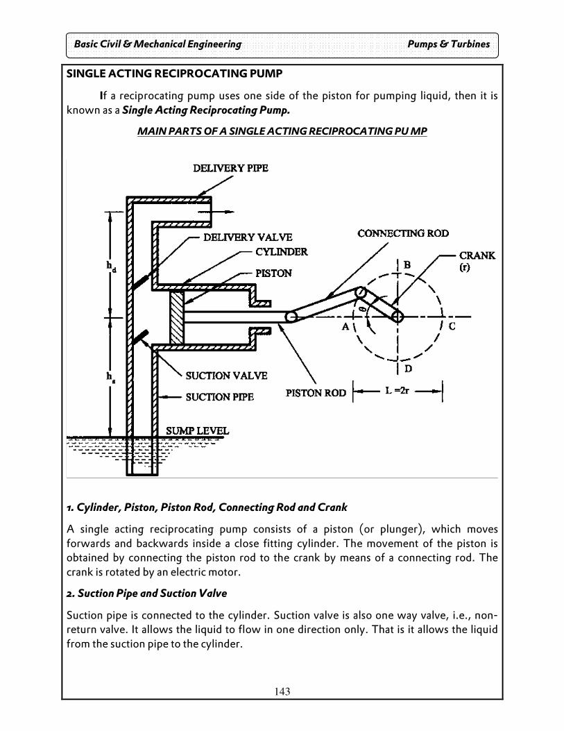
143
SINGLE ACTING RECIPROCATING PUMP
If a reciprocating pump uses one side of the piston for pumping liquid, then it is known as a Single Acting Reciprocating Pump.
MAIN PARTS OF A SINGLE ACTING RECIPROCATING PU MP
1. Cylinder, Piston, Piston Rod, Connecting Rod and Crank
A single acting reciprocating pump consists of a piston (or plunger), which moves forwards and backwards inside a close fitting cylinder. The movement of the piston is obtained by connecting the piston rod to the crank by means of a connecting rod. The crank is rotated by an electric motor.
2. Suction Pipe and Suction Valve
Suction pipe is connected to the cylinder. Suction valve is also one way valve, i.e., non-return valve. It allows the liquid to flow in one direction only. That is it allows the liquid from the suction pipe to the cylinder.
Basic Civil & Mechanical Engineering Pumps & Turbines
144
3. Delivery Pipe and Delivery Valve Delivery pipe is connected to the cylinder. Delivery valve is also one way valve or non-return valve. It allows the liquid to flow in one direction only. That is, it allows the liquid from the cylinder to the delivery pipe. Working principle When a crank starts rotating the piston moves to and fro in the cylinder. When the crank is at A, the piston is at the extreme left position in the cylinder called Inner Dead Centre. Suction stroke
As the crank rotates from A to C (i.e. crank angle increases from 0o to 180o), the piston moves towards right in the cylinder. This is called suction stroke. Now, the volume covered by the piston within the cylinder increases. On the free surface of water in, atmospheric pressure acts. Thus there is a pressure difference at the two ends of the suction pipe which connects the sump and cylinder. During this stroke, the non return valve at the delivery side will be closed by the atmospheric pressure existing in the delivery pipe. At end of this stroke, the cylinder will be full of water . Since, the water is continuously sucked in to the cylinder, this stroke is called suction stroke. At the end of this stroke, since the pressure in the cylinder is atmospheric, the suction valve is closed. Return Stroke or Delivery Stroke When the crank rotates from C to A (i.e. crank angle increases from 180o to 360o), the piston from its extreme right position starts moving towards left in the cylinder. This is known as Return or Delivery stroke. The movement of piston towards left increases the pressure of the liquid inside the cylinder to a pressure more than atmospheric pressure. Therefore, the suction valve closes and delivery valve opens . Now the liquid inside the cylinder is forced into the delivery pipe through valve. Consequently, the liquid is raised to the required height.
Basic Civil & Mechanical Engineering Pumps & Turbines
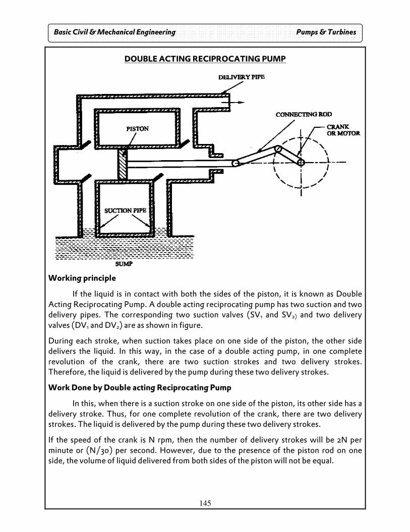
145
DOUBLE ACTING RECIPROCATING PUMP
Working principle
If the liquid is in contact with both the sides of the piston, it is known as Double Acting Reciprocating Pump. A double acting reciprocating pump has two suction and two delivery pipes. The corresponding two suction valves (SV1 and SV2) and two delivery valves (DV1 and DV2) are as shown in figure.
During each stroke, when suction takes place on one side of the piston, the other side delivers the liquid. In this way, in the case of a double acting pump, in one complete revolution of the crank, there are two suction strokes and two delivery strokes. Therefore, the liquid is delivered by the pump during these two delivery strokes.
Work Done by Double acting Reciprocating Pump
In this, when there is a suction stroke on one side of the piston, its other side has a delivery stroke. Thus, for one complete revolution of the crank, there are two delivery strokes. The liquid is delivered by the pump during these two delivery strokes.
If the speed of the crank is N rpm, then the number of delivery strokes will be 2N per minute or (N/30) per second. However, due to the presence of the piston rod on one side, the volume of liquid delivered from both sides of the piston will not be equal.
Basic Civil & Mechanical Engineering Pumps & Turbines
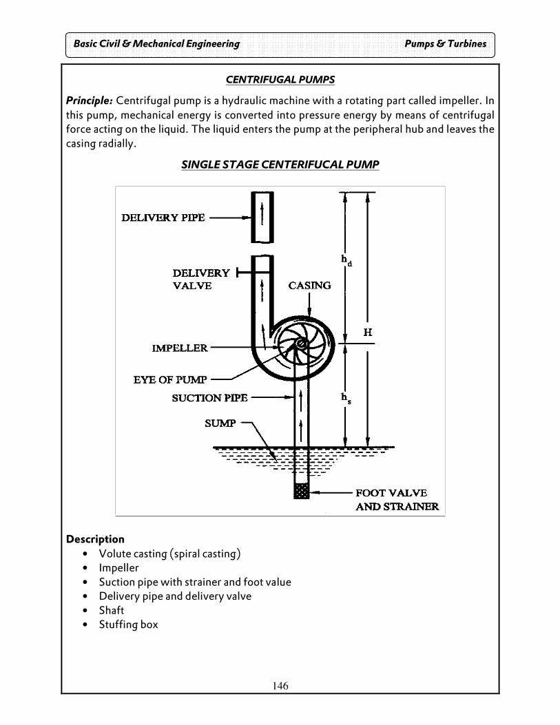
146
CENTRIFUGAL PUMPS
Principle: Centrifugal pump is a hydraulic machine with a rotating part called impeller. In this pump, mechanical energy is converted into pressure energy by means of centrifugal force acting on the liquid. The liquid enters the pump at the peripheral hub and leaves the casing radially.
SINGLE STAGE CENTERIFUCAL PUMP
Description
• Volute casting (spiral casting) • Impeller • Suction pipe with strainer and foot value • Delivery pipe and delivery valve • Shaft • Stuffing box
Basic Civil & Mechanical Engineering Pumps & Turbines
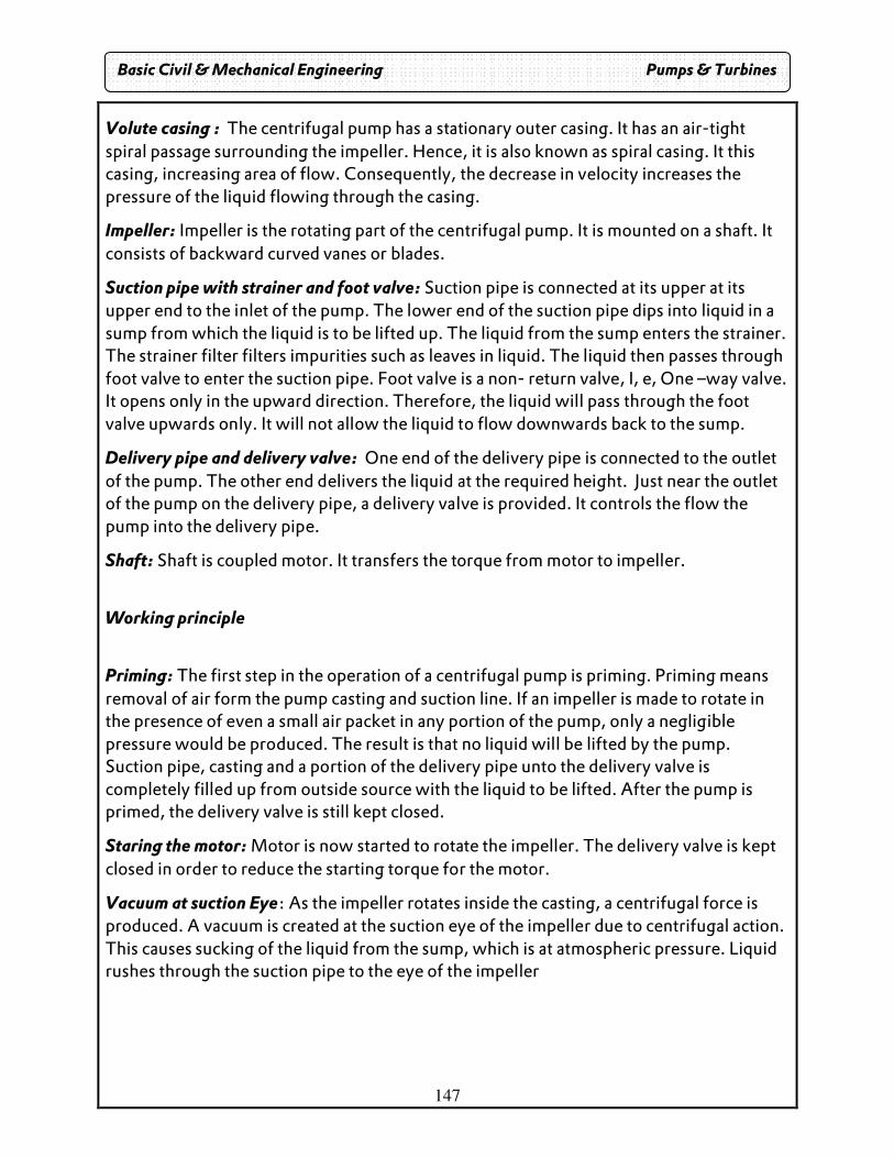
147
Volute casing : The centrifugal pump has a stationary outer casing. It has an air-tight spiral passage surrounding the impeller. Hence, it is also known as spiral casing. It this casing, increasing area of flow. Consequently, the decrease in velocity increases the pressure of the liquid flowing through the casing.
Impeller: Impeller is the rotating part of the centrifugal pump. It is mounted on a shaft. It consists of backward curved vanes or blades.
Suction pipe with strainer and foot valve: Suction pipe is connected at its upper at its upper end to the inlet of the pump. The lower end of the suction pipe dips into liquid in a sump from which the liquid is to be lifted up. The liquid from the sump enters the strainer. The strainer filter filters impurities such as leaves in liquid. The liquid then passes through foot valve to enter the suction pipe. Foot valve is a non- return valve, I, e, One –way valve. It opens only in the upward direction. Therefore, the liquid will pass through the foot valve upwards only. It will not allow the liquid to flow downwards back to the sump.
Delivery pipe and delivery valve: One end of the delivery pipe is connected to the outlet of the pump. The other end delivers the liquid at the required height. Just near the outlet of the pump on the delivery pipe, a delivery valve is provided. It controls the flow the pump into the delivery pipe.
Shaft: Shaft is coupled motor. It transfers the torque from motor to impeller.
Working principle
Priming: The first step in the operation of a centrifugal pump is priming. Priming means removal of air form the pump casting and suction line. If an impeller is made to rotate in the presence of even a small air packet in any portion of the pump, only a negligible pressure would be produced. The result is that no liquid will be lifted by the pump. Suction pipe, casting and a portion of the delivery pipe unto the delivery valve is completely filled up from outside source with the liquid to be lifted. After the pump is primed, the delivery valve is still kept closed.
Staring the motor: Motor is now started to rotate the impeller. The delivery valve is kept closed in order to reduce the starting torque for the motor.
Vacuum at suction Eye: As the impeller rotates inside the casting, a centrifugal force is produced. A vacuum is created at the suction eye of the impeller due to centrifugal action. This causes sucking of the liquid from the sump, which is at atmospheric pressure. Liquid rushes through the suction pipe to the eye of the impeller
Basic Civil & Mechanical Engineering Pumps & Turbines
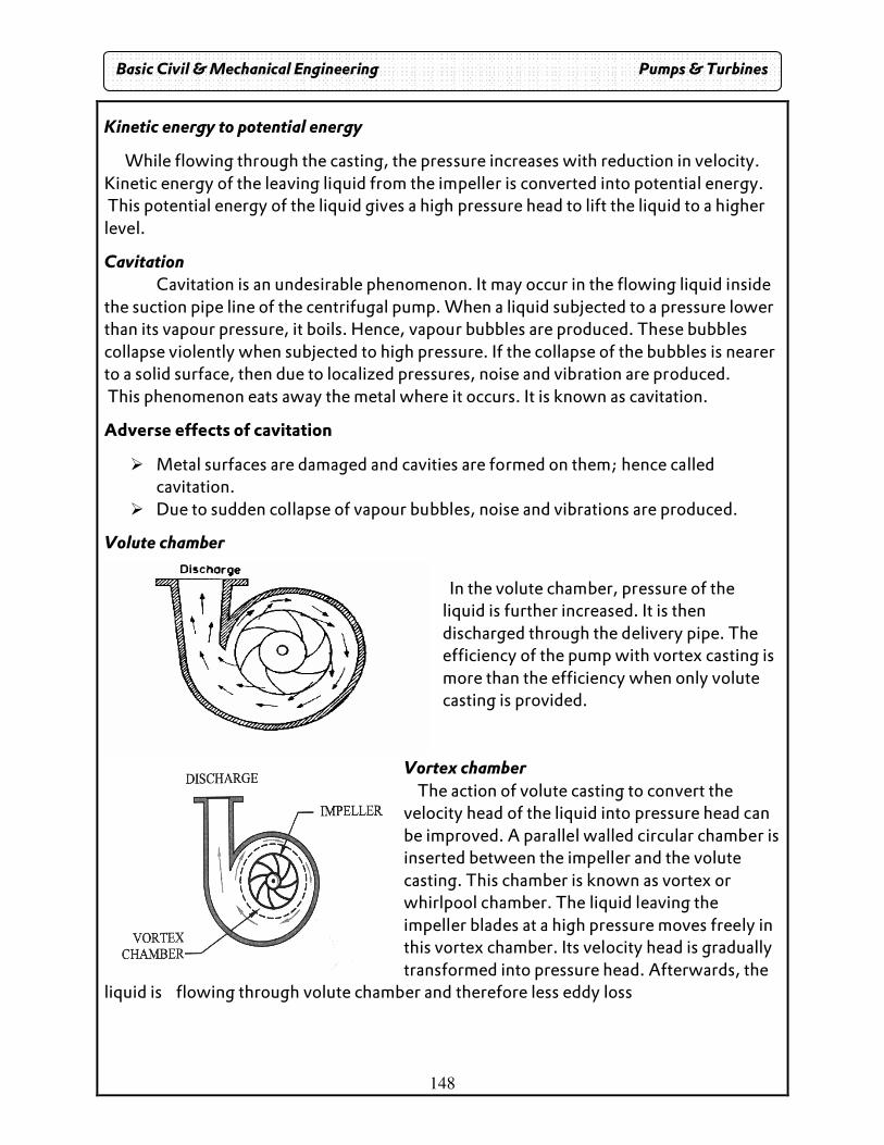
148
Kinetic energy to potential energy
While flowing through the casting, the pressure increases with reduction in velocity. Kinetic energy of the leaving liquid from the impeller is converted into potential energy. This potential energy of the liquid gives a high pressure head to lift the liquid to a higher level.
Cavitation Cavitation is an undesirable phenomenon. It may occur in the flowing liquid inside
the suction pipe line of the centrifugal pump. When a liquid subjected to a pressure lower than its vapour pressure, it boils. Hence, vapour bubbles are produced. These bubbles collapse violently when subjected to high pressure. If the collapse of the bubbles is nearer to a solid surface, then due to localized pressures, noise and vibration are produced. This phenomenon eats away the metal where it occurs. It is known as cavitation.
Adverse effects of cavitation
� Metal surfaces are damaged and cavities are formed on them; hence called cavitation.
� Due to sudden collapse of vapour bubbles, noise and vibrations are produced.
Volute chamber In the volute chamber, pressure of the liquid is further increased. It is then discharged through the delivery pipe. The efficiency of the pump with vortex casting is more than the efficiency when only volute casting is provided.
Vortex chamber The action of volute casting to convert the velocity head of the liquid into pressure head can be improved. A parallel walled circular chamber is inserted between the impeller and the volute casting. This chamber is known as vortex or whirlpool chamber. The liquid leaving the impeller blades at a high pressure moves freely in this vortex chamber. Its velocity head is gradually transformed into pressure head. Afterwards, the
liquid is flowing through volute chamber and therefore less eddy loss
Basic Civil & Mechanical Engineering Pumps & Turbines
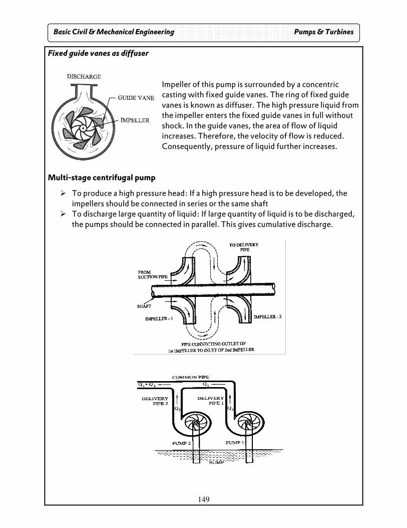
149
Fixed guide vanes as diffuser Impeller of this pump is surrounded by a concentric casting with fixed guide vanes. The ring of fixed guide vanes is known as diffuser. The high pressure liquid from the impeller enters the fixed guide vanes in full without shock. In the guide vanes, the area of flow of liquid increases. Therefore, the velocity of flow is reduced. Consequently, pressure of liquid further increases.
Multi-stage centrifugal pump
� To produce a high pressure head: If a high pressure head is to be developed, the impellers should be connected in series or the same shaft
� To discharge large quantity of liquid: If large quantity of liquid is to be discharged, the pumps should be connected in parallel. This gives cumulative discharge.
Basic Civil & Mechanical Engineering Pumps & Turbines
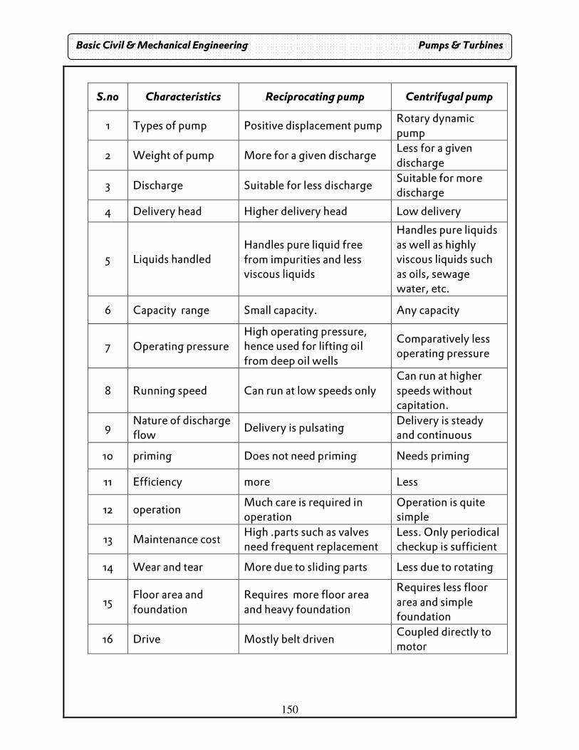
150
S.no Characteristics Reciprocating pump Centrifugal pump
1 Types of pump Positive displacement pump Rotary dynamic pump
2 Weight of pump More for a given discharge Less for a given discharge
3 Discharge Suitable for less discharge Suitable for more discharge
4 Delivery head Higher delivery head Low delivery
5 Liquids handled Handles pure liquid free from impurities and less viscous liquids
Handles pure liquids as well as highly viscous liquids such as oils, sewage water, etc.
6 Capacity range Small capacity. Any capacity
7 Operating pressure High operating pressure, hence used for lifting oil from deep oil wells
Comparatively less operating pressure
8 Running speed Can run at low speeds only Can run at higher speeds without capitation.
9 Nature of discharge flow
Delivery is pulsating Delivery is steady and continuous
10 priming Does not need priming Needs priming
11 Efficiency more Less
12 operation Much care is required in operation
Operation is quite simple
13 Maintenance cost High .parts such as valves need frequent replacement
Less. Only periodical checkup is sufficient
14 Wear and tear More due to sliding parts Less due to rotating
15 Floor area and foundation
Requires more floor area and heavy foundation
Requires less floor area and simple foundation
16 Drive Mostly belt driven Coupled directly to motor
Basic Civil & Mechanical Engineering Pumps & Turbines

151
UNIT IV I C ENGINES
EC ENGINE:
Combustion of fuel takes place outside working cylinder. Combustion of fuel takes palace in a boiler. The steam so produced is made to act on the piston.
I C ENGINE Combustion of fuel takes place inside working cylinder.
I C Engines
Spark (Petrol) Compression ignition (diesel) 4s 2s 4s 2s
Engine Cylinder:
o It is a sleeve into which close fitting piston com slide to make strokes o The cylinder head contains the position for placing the inlet and exhaust
valves. Piston:
The piston is connected to a mechanism which control its sliding. The moment of the piston changes the volume and provides combustion.
Piston rings: It provides Pressure fight seal and it is used for Heat conduction. It Prevents oil
entering between piston and wall.
Piston pin: It connects piston and connecting rod.
Connecting rod: It converts up & down motion into rotary motion.
Crank: It receives power from connecting rod and transmits the power to the crank shaft.
Crank Case:
It holds cylinder and crank shaft and serves as oil sump.
Basic Civil & Mechanical Engineering Internal Combustion Engines

152
TERMINOLOGY: Bore: The inside dia of cylinder. Stroke: Linear distance measured parallel to axis of cylinder from TDC to BDC. TDC: Extreme position of piston on the top volume is maximum. BDC: Extreme position of piston on the top volume is minimum. Compression ratio: Ratio of volume when piston is at BDC to when the piston is at TDC.
FOUR STROKE PETROL ENGINE
DEFINITION: In 4 stroke there is one power stroke in every 4 strokes (or) two rows of cranks. It is also known as S.I. Engine because spark plug ignites the air –fuel mixture.
SUCTION: During suction stroke inlet value opens and air –fuel mixture is sucked into cylinder - The piston moves from TDC to BDC - During suction stroke the exhaust value is closed
Basic Civil & Mechanical Engineering Internal Combustion Engines

153
COMPRESSION STROKE:
� Both inlet and exhaust valve are closed.
� The piston moves from BDC to TDC.
� The air –fuel mixture is compressed.
� Shortly below piston reaches TDC, the charge is ignited by means of spark
plug and pressure. The combustion occurs. These two strokes complete
one revolution.
POWER STROKE:
� During this Stroke both valves remain closed.
� Due to rise in pressure the piston is pushed down with great force and the
piston reaches BDC.
� his is also working stroke as the work is down by expression of hot gases.
EXHAUST:
� During this stroke the exhaust valve opens.
� The movement of piston from BDC to TDC pushes out the hot exhaust gases
through exhaust valve.
� This computes the cycle again the inlet value opens and operations are repeated.
FOUR STROKE DIESEL ENGINE:
Diesel engine is also knows as IC since ignitions takes place due to high
temperature produced during the compression as air . The fuel is injected in the form as fine spray with help of fuel injector.
Suction:
� During suction stroke the inlet value opens and air is down into cylinder.
� The piston moves from TDC to BDC
� The exhaust value is closed in this stroke.
Basic Civil & Mechanical Engineering Internal Combustion Engines

154
Basic Civil & Mechanical Engineering Internal Combustion Engines

155
Compression Stroke:
o Both inlet and exhaust value are closed.
o The piston moves from BDC to TDC.
o The air is compressed to high pressure & temperature.
o Just below piston reaches TDC, the fuel ignited in the form of spray through
fuel injector.
o At this movement the fuel ignited and started burning and high pressure
produced.
Power Stroke:
o This high pressure focuses the piston down from exhausted TDC to BDC. It is also known as working stroke because the work is done by the gases. During this strokes both values remains closed.
Exhaust:
� Here the inlet valve is closed and the exhaust valve is kept opened
and the waste gases are sent out through this valve only.
� The piston moves from BDC to TDC
� The crank shaft will make 2 complete revolutions.
TWO STROKE PETROL
- In 2 strokes engine there is one power stroke for every 2 strokes.
- It will be easier to describe the cycle beginning at end as compression
stroke.
FIRST STROKE (Power and Exhaust):
o Shows the piston at the end of compression.
o Spark plug is ignited.
o The pressure and temperature increased and hence the gases push the
piston downwards producing power stroke.
Basic Civil & Mechanical Engineering Internal Combustion Engines

156
o When the piston moves down the exhaust port opens and the products of
combustion are exhausted to the atmosphere causing exhaust stroke.
o A little later the compressed mixture of air and fuel is transferred to upper
part of cylinder, and the exhaust gases are pushed out with help of
compressed charge. This is known as scavenging.
Basic Civil & Mechanical Engineering Internal Combustion Engines

157
SECOND STROKE (Suction and Compression):
� As the piston moves upwards it covers the transfer port. Therefore the flow of
charge is stopped.
� The upward motion of piston lowers the pressure in the crank case below the
atmosphere and fresh air fuel mixture is introduced into crank case through inlet
port producing suction stroke.
� A little later, the piston covers the exhaust port and actual compression of charge
starts causing compression stroke and the operations are repeated.
� Thus the cycle is completed with in two strokes.
TWO-STROKE DIESEL ENGINE
Definition: In 2 strokes engine there is one power stroke for every 2 strokes. It will be
easier to describe the cycle beginning at end as compression stroke.
Introduction: The air enclosed in the cylinder and it is compressed and its temperature
rises. Diesel which can’t be vaporized and it is injected with the help of fuel injector. The
working is similar to that of petrol engine except fuel injector is used instead 0f spark plug
and air is used as inlet instead of air fuel mixture in petrol engine.
FIRST STROKE (Power and Exhaust):
o Shows the piston at the end of compression.
o Fuel is injected from fuel injector.
o The pressure and temperature increased and hence the gases push the piston
downwards producing power stroke.
o When the piston moves down the exhaust port opens and the products of
combustion are exhausted to the atmosphere causing exhaust stroke.
o A little later the air is transferred to upper part of cylinder, and the exhaust gases
are pushed out with help of compressed charge. This is known as scavenging.
Basic Civil & Mechanical Engineering Internal Combustion Engines

158
SECOND STROKE (Suction and Compression):
� As the piston moves upwards it covers the transfer port. Therefore the flow of
charge is stopped.
� The upward motion of piston lowers the pressure in the crank case below the
atmosphere and fresh air is introduced into crank case through inlet port producing
suction stroke.
� A little later, the piston covers the exhaust port and actual compression of charge
starts causing compression stroke and the operations are repeated.
� Thus the cycle is completed with in two strokes.

159
S. No Details Petrol engine Diesel engine
1 Fuel Ignition By spark plug (spark- ignition) Engine
By hot compressed air (compression-ignition
engine) 2 Charge during
suction stroke Air and fuel mixture are
admitted Air alone is admitted and
fuel is injected 3 Compression ratio Low (6 to 8) High (16 to 20)
4 Fuel admission Through Carburetor Through fuel injector
5 Cycle of operations Otto cycle (Constant volume cycle)
Diesel cycle (Constant pressure cycle)
6 Engine speed High speed – about 3000 rpm
Low speed 400 – 1500 rpm
7 Engine starting in cold weather
Easy Difficult due to high compression ratio
8 Engine cost Less more
9 Fuel consumption More Less
10 Fuel cost Less More
11 Maintenance Requires change of spark plug after few thousand
kilometers
Fuel injection doesn’t require frequent
maintenance. 12 Weight Light Heavy
13 Uses Automobiles and aero planes
Buses, tractors, trucks etc
14 Vibration and noise Almost nil More due to high operating pressure.
15 Vehicle chassis Due to less weight of engine and smooth
working, vehicle chassis is not made very strong
Due to heavy weight of engine and more vibration,
chassis is made extra strong.
Basic Civil & Mechanical Engineering Internal Combustion Engines

160
UNIT V REFRIGERATION AND AIR CONDITIONING SYSTEM
Principle:
Continuous extractions of heat from a body for e.g. if some space is to be kept to say -5oC. The heat is extracted continuously as it flows due to leakage through the walls. It is based on 2nd law of Thermodynamics: It is impossible for a self acting machine working in a cyclic manner to transfer the heat from a body at a low temperature to a body at higher temperature without aid of external source.
Terminology
Refrigeration: The processes of removing heat to reduce its temperature lower than
surroundings.
Refrigerator: This equipment is used for producing and maintaining the temperature in a space
below the atmospheric temperature.
Refrigerant: It is a working fluid used in the refrigerator such that liquid evaporates at lower
temperature and it will absorb the heat extracted from surroundings.
Capacity of Refrigerator: It is the rate at which heat can be exhausted from the cold body i.e., amount of
refrigerant is produced. It is expressed in terms of tons of refrigeration [one tone of refrigeration is equal to
amount of refrigeration produced by melting of 1 tone of ice in 24hrs] =3.5 kj/sec.
Coefficient of performance: It is the ratio of heat absorbed to work done.
C.O.P. =heat absorbed/ Work done
Important refrigerants: � Ammonia - boiling point -33oC � Freon - boiling point - -30oC
Properties: � low boiling point � low specific heat � low volume � Should have high C.O.P. � non explosive � non toxic
Basic Civil & Mechanical Engineering Refrigeration & Air-Conditioning

161
Vapour Compression Refrigerator: Evaporator:
It consists of coiled tube which is installed in the refrigerated space. The evaporator tube is connected to a Rotary compressor. The delivery side of the compressor is connected to a condenser. The condenser is connected to throttle value (or) expansion value.
Working: o The low pressure low, low temperature Vapour enters into
Compressor and compressor increases pressure and temperature. o The compressed high pressure and high temperature vapour enters into
condenser. o In the condenser the vapour cools and becomes liquid. Therefore high
pressure low temperature liquid enters into the throttle value. o The throttle value reduces the pressure and this low pressure low
temperature liquid enters into evaporator and this liquid absorbs the heat from the refrigerator space and evaporates. This will lower the temperature in the refrigerator space and this vapour is again compressed to high pressure and high temperature in the compressor and operations are repeated.
o The required low temperature is maintained by a thermostat which is used to switch ON or OFF the compressor or by a relay.
Basic Civil & Mechanical Engineering Refrigeration & Air-Conditioning

162
VAPOUR ABSORPTION
o The Vapour Absorption differs from vapor compression type only in the method of compressor. The compressor is replaced by absorber, generator and pump.
o AQUA- AMMONIA (H2O + NH3) is used and by subsequent heating it gives of vapor low pressure weak NH3 solution which is sprayed on top of the absorber.
o The NH3 vapor is absorbed by the solution and producing low pressure
strong NH3 solution. o The pump pumps strong solution to heat exchanger.
Basic Civil & Mechanical Engineering Refrigeration & Air-Conditioning

163
o This HP strong. NH3 enters into H.E. where it is heated by HT weak NH3 from generator
o Therefore HP, HT strong NH3 solution is produced in H.E. and it is sent to generator
o The HP, HT Vapour is produced in the generator by heating the solution in the generator using external source like heater.
o The solution in the generator becomes weak and it is passed to absorber through throttle value & H.E. where pressure and temp is reduced. This is again circulated.
o This H.P. H.T. Vapour is sent to condenser and HP, CT NH3 liquid is produced
o Then it is sent to throttle value where it produces LP,LT NH3 liquid. o The ammonia absorbs the heat and evaporates to produce the cooling effect o The NH3 vapor is again sent to absorber and process is repeated.
WINDOW AIR CONDITIONING
Psychometric: Study of behavior of air and water vapour mixture.
Moisture: The water vapour pressure in air
Humidity: The amount of water vapour pressure in air.
Relative Humidity. The ratio of mass of water vapour to total mass of air.
Normal R.H.60%, Hot Weather (23 0C, 60%)
Principle: � Air conditioning system for dry weather e.g. Delhi
� Temp 40oC & R.H. 15 to 20% comfort condition: 23oC & 60% RH Air passes
through Dampers and it controls the air.
� Than air Passes through filter which removes dust .
� Then it passes through cooling coil where temperature is reduced and it passes
through spray type humidifier where humidity is increased.
Vapour compression Vapour Absorption 1. Lower Capacity Higher capacity eg. 1000 tones 2. Noisy operation Quiet operation 3. Low C.O.P. High C.O.P. 4. High Maintenance cost Lower maintenance cost 5. C.O.P. decreases at full load C.O.P increases at full load.
Basic Civil & Mechanical Engineering Refrigeration & Air-Conditioning

164
WET WEATHER (15 0C, 75%)
� The cool air passes through cooling coil, where water Vapour is removed and then
passes through heater and temp is increased.
Working principle of Window Air-conditioning � The low pressure low temperature refrigerant enters into compressor which
increases the pressure.
� This air enters into a condenser which is cooled by air from the fan.
� Then this low temperature high pressure air enters into throttle value and pressure
is reduced.
Basic Civil & Mechanical Engineering Refrigeration & Air-Conditioning

165
� Then low temperature low pressure liquid enters into evaporator. � The Blower sucks warm surrounding air from the room and forces on to the
evaporator. � The liquid in the evaporator evaporates and takes the heat from the air and cooled
it. This cooled air is flowing into room. � The thermostat is provided to compressor to maintain the desired temperature,
which is operated by on or off switch. � A damper is used to regulate the fresh air supply.
Advantages:
� Low cost � Operation control is easy. � More COP.
Dis advantages:
Noisy operation. More vibration. Requires more space
Basic Civil & Mechanical Engineering Refrigeration & Air-Conditioning

166
Split Air Conditioning
Split type: Now a day’s split air conditioner is being used because, it is more efficient and
less noisy. The noise making components like compressor and condenser are fitted
outside. It has two main components: out door, Indoor
Out door: Out door unit consist of compressor and condenser.
Indoor unit: It consists of power cables, Refrigerant tubes and evaporator. In earlier days
our Air- conditioners used CFC, which affects the ozone layer. It is stopped in the year
1995. Now it uses HCFC (Halogenated CFC). And a thermostat is used to heat the room at
constant temperature.
Working principle of Split Air-conditioning
� The low pressure low temperature refrigerant enters into compressor which
increases the pressure.
� This air enters into a condenser which is cooled by air from the fan.
Basic Civil & Mechanical Engineering Refrigeration & Air-Conditioning

167
� Then this low temperature high pressure air enters into throttle value and pressure
is reduced.
� Then low temperature low pressure liquid enters into evaporator.
� The Blower sucks warm surrounding air from the room and forces on to the
evaporator.
� The liquid in the evaporator evaporates and takes the heat from the air and cooled
it. This cooled air is flowing into room.
� The thermostat is provided to compressor to maintain the desired temperature,
which is operated by on or off switch.
� A damper is used to regulate the fresh air supply.
Advantages:
� Noiseless operation.
� Less vibration.
� Compact unit.
Disadvantages:
High cost
Operation control is difficult.
COP is poor.
More leakage because of longer line.
COMPARISON OF UNITARY SYSTEM AND CONTROL SYSTEM
Unitary system Control system
1. Factory assembled File assembled 2. Located near conditioned space Away from conditioned space 3. Duct work is eliminated Duct work is reduced 4. More persons required Less persons is required. 5. System failure affect only one room
System failure affects all room.
Basic Civil & Mechanical Engineering Refrigeration & Air-Conditioning

168
Domestic Refrigerator layout.
Basic Civil & Mechanical Engineering Refrigeration & Air-Conditioning

169

170
Two Mark Questions & Answers

171

172
UNIT III POWER PLANT ENGINEERING
1. What are the different sources of energy?
� Hydro power, nuclear energy, fossil fuels, wind energy, solar energy, tidal power, and geo thermal energy.
2. Name four non-renewable sources of energy.
� Liquid fuels like petrol, solid fuels like coal, gaseous fuels like natural gas and nuclear fuels like uranium, thorium.
3. Name some renewable sources of energy.
� Renewable sources of energy are also called as alternative sources. They are solar energy, hydal energy, tidal energy, wind energy and geo thermal energy.
4. What is the difference between renewable and non- renewable energy sources of energy?
� Renewable sources of energy are not consumed and inexhaustible, examples are solar energy and wind energy. Non-renewable sources of energy are either consumed or converted into other forms. Examples are coal and petrol.
5. Give two applications of wind energy.
� Wind can be used to run the power plant to generate electricity � To pump water.
6. Name four solid fuels.
� Coke, Coal, Wood, and Peat. 7. Name four liquid fuels.
� Petrol, Diesel, Kerosene, and Furnace oil.
8. Name four gaseous fuels.
� Natural gas, producer gas, flue gas, blast furnace gas.
Basic Civil & Mechanical Engineering Two Mark Questions & Answers

173
9. Name two nuclear fuels.
� Uranium and plutonium. 10. Name four nuclear reactor sites in India.
� Narora – Uttar Pradesh � Kalpakkam – Tamilnadu (Near Chennai) � Kakrapur – Gujarat (Near Surat)
11. What are the disadvantages of wind energy?
� Occupies large area � Noisy operation � Initial investment is high
12. Give two applications of nuclear energy.
� Nuclear power plants to generate electricity � Nuclear missiles (war heads)
13. Is coal as a fossil fuel?
� Yes, coal is a fossil fuel. 14. What is meant by tide?
� The rise and fall of sea water at intervals is called tide. 15. How are tide caused?
� Tides are caused by the gravitational attraction of the moon and sun on the ocean.
� About 70% of the tide is produced due to the moon and 30% due to the sun. 16. What is geo thermal energy?
� It is the energy present as heat (thermal energy) in the earth’s crust.
Basic Civil & Mechanical Engineering Two Mark Questions & Answers

174
17. What is the other name for nuclear energy?
� The other name for nuclear for nuclear is atomic energy. 18. What is bio-mass?
� Bio-mass is organic matter produced by plants, forest corps, industrial waste, animal waste, sewer, vegetable waste, pig manures and other organic waste. By using this waste bio-mass waste is obtained.
19. What is bio-gas?
� Bio-gas is also called as gobar gas. It is the gas obtained by fermenting bio-mass. This gas can be used for cooking. The gas consists of methane (55%), carbon dioxide (35%), nitrogen (2.4%), Hydrogen (7.6%), and traces of other gases.
20. How much of wind speed is considered for economical power generation?
� A mean annual wind speed of about 20m above 20m above the ground of 18 km/ph is considered as a minimum requirement for economic power generation of electricity.
21. Mention the applications of solar energy.
� (i) Solar cooking (ii) solar pumping (iii) Solar furnaces (iv) Solar heating of buildings (v) solar water heater (vi) Solar coolers (vii) Solar distillation and solar power generation.
22. Define power plant.
� Power plant is a machine or assemblage of equipments that produces and delivers a flow of electrical energy.
23. What are the different types of power plants?
� Steam power plant � Hydel power plant � Nuclear power plant � Gas turbine power plant � Tidal power plant
Basic Civil & Mechanical Engineering Two Mark Questions & Answers

175
24. Give the function of condenser in steam power plant.
� Condenser is used to condense the steam from the turbine and again fed to the boiler.
25. What is the function of moderator in a nuclear power plant?
� Moderator is used to slow down the fast moving electrons in the nuclear reactor, which are produced during nuclear fission.
26. Give important factors to be considered for selecting hydroelectric power plant.
� Availability of water � Water storage � Water head � Distance form load centre.
27. Mention the reason for preferring steam power plant to other power plants.
� Less space required. � Initial cost is low. � Respond to changing load. � Continuous power generation.
28. What is a cooling tower? Give its uses.
� Cooling tower is an arrangement where cold water is sprayed to cool the water coming out of the condenser.
29. What are the nuclear fuels used in the nuclear reactor?
� Uranium235, Uranium238, plutonium. 30. What is the function of penstock pipe?
� Penstock is closed pipe made of steel or concrete used for supplying water from surge tank to the turbine.
Basic Civil & Mechanical Engineering Two Mark Questions & Answers

176
31. What is mean by nuclear fission?
� Nuclear fission is the process of splitting the nucleus of fissionable material like uranium into two or more fragments with release of enormous amount of energy.
32. What is the function of intercooler in gas turbine power plant?
� Inter cooler is used to reduce the work of the compressor and increase the efficiency.
33. Name the different components of a gas turbine power plant.
� Low pressure compressor, High pressure compressor, Intercooler, regenerator, Combustion chamber, low pressure turbine and high pressure turbine.
34. Briefly explain what radiation shielding means?
� A thermal shield is provided through steel lining and another shield of thick concrete is also provided around the nuclear reactor. This is called radiation shielding and is used to protect the reactor. This is called radiation shielding and is used to protect the reactor against the harmful rays and fast neutrons.
35. What are the different types of hydro power plants?
� High head hydro power plants. � Medium head hydro power plants. � Low head hydro power plants.
36. State the disadvantages of steam power plant.
� Erection requires long time. � Less efficiency. � Transportation of fuel is a problem.
37. Mention the application of gas turbine power plants.
� Petrochemical industries. � Used in air craft and ships. � Standby unit.
Basic Civil & Mechanical Engineering Two Mark Questions & Answers

177
38. What are the different types of wind mill?
� Horizontal axis wind mill – (a) Single bladed (b) Multi blade. � Vertical axis wind mill - (a) Savonious type (b) Derrieus type.
39. State the advantages of tidal power plant.
� Tidal energy is inexhaustible in nature. � Free from pollution. � Requires smaller land area. � No fuel is required.
40. Define steam turbine.
� A steam turbine is prime mover which converts heat energy in the steam into mechanical work.
41. State the main parts of a steam turbine.
� Nozzle � Rotor � Rotor blades
42. How steam turbines are classified?
� Impulse turbine � Reaction turbine
43. Give an example for reaction turbine.
� Parson’s turbine. 44. State the limitations of an impulse turbine.
� Suitable for low pressure steam � Out let velocity of steam.
Basic Civil & Mechanical Engineering Two Mark Questions & Answers

178
45. What is the difference between impulse and reaction turbine?
� In a impulse turbine, the steam coming out of the turbine has only kinetic energy, where as in reaction turbine, the steam out of the turbine has both pressure and kinetic energy.
46. Relative velocity of steam increases in reaction turbine. Give reason.
� The relative velocity of steam increases in moving blades of the reaction turbine due to the continuous expansion of steam.
47. What are the advantages of centrifugal pump?
� The cost of a centrifugal pump is less as it has fewer parts. � Installation and maintenance are easier and cheaper. � It is compact and as smaller size and weight.
48. What is meant by centrifugal pump?
If the mechanical energy is converted, into pressure energy by means of centrifugal force acting on the fluid, the hydraulic machine is called centrifugal pump.
49. What is meant by reciprocation pump?
If the mechanical energy is converted into hydraulic energy (or pressure energy) by sucking the liquid into a cylinder in which a piston is reciprocating (moving backward and forwards), which exert the thrust on the liquid and increases its hydraulic energy (pressure energy), the pump is called reciprocating pump.
50. What is meant by multistage pump?
To get the high head, number of impeller are connected in series on the same shaft is called multistage pump.
51. What is meant by priming?
Before starting the pump, air from suction pipe, casing and portion of delivery pipe up to the valve is replaced by water. The operation of replacing the air with water in the pump is called priming.
Basic Civil & Mechanical Engineering Two Mark Questions & Answers

179
52. Difference between single acting reciprocating pump and double acting reciprocating pump?
S.No Single acting Reciprocating Pump
Double acting Reciprocating Pump
1. It has one suction pipe and one delivery pipe.
It has two suction pipe and two delivery pipe.
2. One complete revolution of the crank there are one delivery stroke.
One complete revolution of the crank there are two delivery stroke.
53. Difference between Centrifugal Pump and Reciprocating Pump?
S.no Centrifugal Pump Reciprocating Pump 1. The discharge is continuous and
smooth The discharge is not continuous. It is fluctuating and pulsating.
2. It can be used for lifting highly viscous liquids.
It is meant for small discharge and high heads.
3. It can handle large quantity of liquid.
It handles small quantity of liquid only.
54. Name different types of conventional and non conventional power plants.
CONVENTIONAL NON CONVENTIONAL
Or Renewable or Primary or Non – Renewable or Secondary
Steam hydro electric
Diesel solar
Nuclear tidal
Geothermal
55. What is minimum wind speed and minimum tide height required for power
generation?
� Minimum wind speed: 18kmph
� Minimum tide height: 5m
Basic Civil & Mechanical Engineering Two Mark Questions & Answers

180
56. Name the prime mover in steam power, hydro power plant.
� Steam power plant: steam turbine
� Hydro power plant: hydraulic turbine
57. What is water head and head race?
� Water head: Difference between head race level and tail race level.
� Head race: the level of water stored in the reservoir.
58. What are the classifications of turbine?
� Pelton wheel=>high head=> >70m
� Francis=>medium head=>15-70m
� Kaplan=>low head=> <15m
59. What is the purpose of surge tank?
� It helps to prevent the damage to penstock by water hammer.
60. Define water hammer.
� The pressure in the penstock is known as water hammer.
61. What is the function of moderator and indicate the materials?
� It is used to reduce the speed of fast moving neutrons.
� Materials: heavy water, graphite, beryllium.
62. What is the use of intercooler in gas turbine power plant?
� It is located in between L.p compressor and H.p compressor and it is used to
reduce the load of compressor.
63. What are ebb tides and flood tides?
� When the level of water is above mean sea level=>ebb tide.
� When the level of water is below sea level =>flood tide.
Basic Civil & Mechanical Engineering Two Mark Questions & Answers

181
64. What is the use of turbine?
� Turbine is a rotary engine that extracts energy from a working flood
such as steam, gas and water. a working flood possesses potential and
kinetic energy into mechanical energy.
65. What are the different types of turbine and compare them?
IMPULSE REACTION
It consists of separate fixed it consists of fixed blades and
Nozzles and rotating blades moving blades both acting as nozzles
Steam expands fully in nozzle it expands partly in fixed blades
Overall efficiency is low high
Very much suitable for small high power generation
Power generation
66. What is the use of pump and classify its type?
� It is used to rise or transfer fluids.
Application:
� Draining, sewage, irrigation, chemical industries
Positive displacement pump:
� Here fluid is forced (inlet) into finite space and then it is sealed by
mechanical means. Then the fluid is forced out (discharged).
� E.g.: reciprocating
Roto dynamic:
� Here free passage between the inlet and outlet without sealing.
� E.g.: centrifugal pump
Basic Civil & Mechanical Engineering Two Mark Questions & Answers

182
67. What is the difference between centrifugal and reciprocating pump?
� CENTRIFUGAL PUMP: low head and high discharge
� RECIPROCATING PUMP: high head and low discharge
68. What is mean by multistage pump?
� It contains two or more impellers. it helps to develop high head and high
discharge.
69. What are advantages of centrifugal pump?
� It is reliable.
� It runs smoothly.
� They are easy to install.
� It is compact in size.
70. What are the classifications of centrifugal pumps?
� Radial flow.
� Mixed flow.
� Axial flow.
71. What is the difference between single acting and double acting reciprocating pump?
� In single acting one inlet and one outlet and in double acting there are two inlets
and two outlets. Therefore the discharge is high in double acting reciprocating
pump.
72. Name the Gas, Diesel, Hydel, Thermal and Nuclear power plants in Tamilnadu?
Gas Power Plant
� Perungulam (Natural gas),
� Kovikalappal (oil),
� Basin Bridge (naphtha)
Diesel Power Plant:
� Vasvi (CMS India Limited),
� Samayanallur (Balaji power corporation Ltd)
� Samalpatti (samalpatti Power Corporation).
Basic Civil & Mechanical Engineering Two Mark Questions & Answers

183
Hydel Power Plant:
� Kundah, Kadamparai, Mettur.
Nuclear Power Plant:
� Kalpakkam (Madrs Atomic Power Station),
� Kudankulam (Kudankulam Nuclear Power Plant)
Thermal Power Plant
� Ennore, Neyveli, North Madras and Tuticorin,
73. Define High pressure boilers.
High pressure boilers are used in power plants to generate steam at a high pressure. The
modern high pressure boilers used for power generation have steam capacities ranging
from 40 to 650 tonnes/h with pressure up to 200bar and maximum steam temperature of
about 6000C.
74. What are the special features of high pressure boilers?
� Provision of tubings and drums
� Forced water circulation
� Evaporation of water above critical pressure resulting in the saving of latent heat
� Use of supersaturated steam for heating water.
Basic Civil & Mechanical Engineering Two Mark Questions & Answers

184
UNIT IV I C ENGINES
1. What is an engine?
� An engine is a device used for converting heat energy into mechanical energy by combustion of a fuel.
2. What are the types of heat engine?
� Internal combustion engine (I.C. Engine) � External Combustion engine (E.C. Engine)
3. What is mean by S.I. Engine? Why is it called so?
� Petrol engine is called is as spark ignition, because the combustion of fuel takes place by means of a spark produced by the spark plug.
4. What is mean by C.I. Engine? Why it is called so?
� Diesel is called as compression ignition engine, because the combustion takes place due to the heat produced by the compression of air-fuel mixture.
5. Spark plug is necessary to run a --------------------------- engine.
� Ans: Petrol 6. Give the main components of a petrol engine.
� Cylinder, cylinder head, piston, connecting rod, valves, spark plug, crank shaft, cam shaft and fly wheel.
7. Number of working strokes per minute for a four stroke cycle engines are -------------- the speed of the engine.
� Ans: Half. 8. A petrol engine works on ----------------- cycle.
� Ans: Otto
Basic Civil & Mechanical Engineering Two Mark Questions & Answers

185
9. ----------------- is used to mix fuel and air in a petrol engine.
� Ans: Carburetor. 10. What is a four stroke engine?
� In a four stroke engine, one power stroke is completed for every stokes of the piston or during two revolutions of the crank shaft.
11. Diesel engine works on the principle of ------------------------------ cycle.
� Ans: Diesel cycle. 12. What is the function of a carburetor?
� To mix the fuel with air in correct proportion and to evaporate the fuel with fast moving air.
� To regulate the supply of air -fuel mixture entering into the engine cylinders. 13. What is the fundamental difference between two-stroke and four-stroke engine?
� In four- stroke engine one power stroke is obtained in two revolutions of crank shaft where as in two- stroke engine , one power stroke is obtained in each revolution of crank shaft.
14. Why fuel is injected in a C.I. engine?
� The fuel used in C.I. engine cannot be vaporized and hence injected into the cylinder in the form of fine spray.
15. Define carburetor.
� Carburetor is a device used for mixing the air with petrol in correct proportion. 16. Mention the types of ignition systems used in petrol engine.
� Battery (or) coil ignition system. � Magneto ignition system
Basic Civil & Mechanical Engineering Two Mark Questions & Answers

186
17. State the function of choke in a petrol engine.
� Choke is provided for easy starting of the engine. It allows rich mixture into the cylinder by reducing the amount of air present in the mixture.
18. What is the function of a spark plug?
� Spark plug is a device used to ignite the compressed air fuel mixture by producing an electric spark.
19. The gap between the central electrode and earth electrode of a spark plug is ----------
� Ans: 0.4mm 20. The device used to supply correct quantity of fuel into the cylinder of a diesel engine is ---------------.
� Ans: Fuel pump 21. Define fuel injector
� Fuel injector is a device is device used to atomize the fuel and to deliver the fuel to the cylinder of a diesel engine in the form of fine spray.
22. What are the types of cooling systems used in I.C. engine?
� Air cooling. � Water cooling.
23. Mention the types of water cooling on I.C. engines.
� Natural circulation system � Forced circulation system
24. Define lubrication.
� Lubrication is the process of applying lubricant between the surfaces of contact of two moving parts.
Basic Civil & Mechanical Engineering Two Mark Questions & Answers

187
25. Mention some engine parts that require frequent lubrication.
� Cylinder, piston and piston rings. � Main bearings � Crank shaft � Valves etc.
26. What are the types of lubrications for I. C. engines?
� Mist lubrication. � Wet lubrication.
27. Compression ratio of petrol engine is in the range of (a) 2 to 3 (b) 3 to 5 (c) 7 to 10 (d) 16 to 20
� Ans: (c) 7 to 10 28. Compression ratio of diesel engine is in the rang e of (a) 8 to 10 (b) 10 to 15 (c) 16 to 20 (d) 20 and above
� Ans: (c) 16 t0 20. 29. Fuel injector is used in (a) S.I. engines (b) C.I. engines (c) Gas engines.
� Ans: (b) C.I. engines. 30. What is mean by internal combustion engine?
� Internal combustion engine (I.C. engine) is a heat engine where combustion of fuel (petrol/diesel) with air takes place inside the engine cylinder.
31. What are the main parts of the internal combustion engine?
� The main parts of an internal combustion engine are cylinder, piston, piston rings, piston pin, crank shaft, connecting rod, crank case, valves and flywheel.
Basic Civil & Mechanical Engineering Two Mark Questions & Answers

188
32. How I.C. engines are classified?
� I.C. engines are classified as spark ignition engines (S.I. engines) and compression ignition engines (C.I. engines). Another classification of I.C. engines are (1) Four stroke engine (2) two stroke engine.
33. What are the four stroke of an I.C. engine?
� Suction stroke, compression stroke, expansion or power stroke, working stroke and exhaust stroke.
34. What is mean by stroke in an I.C. engine?
� A stroke refers to the linear distance between the two extreme positions of the piston. This distance is measured parallel along the axis of the cylinder.
35. Name the two extreme positions occupied by the piston?
� The two extreme positions occupied by the occupied by the piston in a cylinder are Top dead centre (TDC) and Bottom dead centre (BDC).
36 Name the important systems in an I.C. engine.
� Fuel system, ignition system, cooling system, lubricating system and air system. 37. What is the main purpose of fuel system in an I.C. engine?
� Storage and supply of fuel for combustion of engines is the main purpose of fuel system.
38. What are the important components of fuel system?
� Fuel filters, fuel tank, carburetor (for S.I.engine), fuel pump and fuel injector (for C.I. engine).
39. What is the basic function of ignition system?
� Ignition system is used in a spark ignition engine to ignite the air fuel mixture in the cylinder
Basic Civil & Mechanical Engineering Two Mark Questions & Answers

189
40. What are the two types of ignition system?
� (1) Battery ignition system (2 ) Magneto ignition system 41. Why cooling system is necessary in an I.C. engine?
� Combustion of air-fuel mixture in the cylinder produces very high temperature in the range of 20000C. This heat may cause expansion of cylinder wall, cylinder head, piston and other parts resulting in abnormal ignition. Cooling system is used to maintain the temperature within limits so that normal ignition occurs.
42. What is the purpose of lubrication system used in I.C. engines?
� Lubricating system is used to reduce the friction between the moving parts and thus reduces its wear and tear. It also cools and cleans the moving parts.
43. What is the compression ratio of an I.C. engine?
� The compression ratio of an I.C. engine is defined as the ratio of maximum cylinder
volume to minimum cylinder volume.
� 44. What is meant by scavenging in I.C. engine?
� Scavenging refers to the process of removing burnt gases during exhaust stroke with the help of incoming charge and deflector.
45. State the purpose of flywheel.
� Flywheel is used to sustain the movement of the piston even during non-power strokes.(Suction, compression and exhaust strokes)
46. What is meant by TDC?
� TDC means top dead centre, it is the extreme position of the piston at the top end of the cylinder in a vertical engine.
Basic Civil & Mechanical Engineering Two Mark Questions & Answers

190
47. What is meant by BDC?
� BDC means Bottom dead centre, it is the extreme position of the piston at the bottom of the cylinder in vertical engine.
48. What is function of I.C. engine?
� I.C. engine is used to produce mechanical energy by burning fuel such as petrol or diesel inside the cylinder.
49. What is the cycle used in SI engine?
� The cycle used in SI engine is OTTO CYCLE. 50. What is the fuel used in SI & CI engine?
� The fuel used in SI & CI engines are PETROL & DIESEL respectively. 51. What is the standard ratio of air-fuel mixture for an SI engine?
� The standard ratio of air-fuel mixture for SI engine is 15:1. 52. What is the crank shaft revolution in 2 Stroke and 4 Stroke?
� 2 Stroke - one revolution. � 4 Stroke - two revolutions.
53. What are the sequences in 4 Stroke engine?
� Suction stroke � Compression stroke � Power stroke � Exhaust stroke
54. What is the use of piston ring?
� The piston is used to lubricating oil on the cylinder walls
Basic Civil & Mechanical Engineering Two Mark Questions & Answers

191
55. What is the use of connecting rod?
� Connecting rod is used as the linear or reciprocating motion of the piston into the rotary motion of crankshaft.
56. What is the use of flywheel?
� It is used to minimize the fluctuation of energy in crankshaft 57. What is the ratio of petrol engine and diesel engine?
� Petrol engine- 7 to 10. � Diesel engine- 15 to 20
58. What is the fundamental difference between 2-stroke and 4-Stroke engine?
� In four stroke engine one power stroke is obtained in two revolutions of crankshaft where as in two stroke engine, one power stroke is obtained in each revolution of crankshaft.
59. Write Short notes on Fly wheel?
� Fly wheel is a fairy large wheel mounted on the crank shaft. During the power stroke, fly wheel stores excess energy and releases it during the other strokes. Thus fly wheel ensures minimum variation in speed.
60. What is clearance volume?
� The volume of cylinder above the top of the piston when the piston is at TDC is called clearance volume.
61. What is gudgeon pin?
� The pin which is used to connect connecting rod and piston is known as gudgeon pin.
Basic Civil & Mechanical Engineering Two Mark Questions & Answers

192
62. Define Otto cycle.
� Ina four stroke cycle petrol engine (also known as spark ignition engine), four strokes of the piston, namely suction, compression, expansion and exhaust take place in one cycle of operation in two revolutions of the crank shaft. This system of operation is known as Otto cycle.
63. What is Scavenging?
� The process of cleaning or removing the burnt exhaust gas by the incoming compressed air-fuel (petrol) mixture is known as scavenging.
STEAM GENERATORS 1. How boilers are classified?
� According to flow of water and gases Fire tube boilers Water tube boilers
� According to pressure Low pressure boilers High pressure boilers 2. Mention the advantages of high pressure boilers?
� Rate of steam production is high � Steam produced at a pressure pf more than 890 bar. � Superheated steam can be produced.
3. State the main function of a boiler
� The main function of a boiler is to evaporate water into steam at a higher pressure.
Basic Civil & Mechanical Engineering Two Mark Questions & Answers

193
4. How modern boilers differ from olden day boilers? Give four important points.
� Steam is produced at high rate. � Steam is produced at a higher pressure. � Suitable mountings avoid the danger and provide safe operation and control. � Boiler accessories fitted increases the efficiency.
5. What is the use of an economizer in a high pressure boiler?
� Economizer extracts the heat from the hot flue gases going out of the boiler and preheats the water that is fed to the boiler.
6. What is the difference between mountings and accessories in a boiler?
� Boiler mountings are fitted in the boiler for safe operation and control steam generation where as boiler accessories increases the boiler efficiency of the boiler.
7. Name any two mountings of a boiler?
� Pressure gauge � Water gauge
8. What is a boiler?
� Boiler is a closed vessel in which steam is generated from water by the application of heat and the pressure being higher than the atmosphere.
9. State the main components of a boiler.
� Shell, furnace, chimney, manhole, super heater etc. 10. What is the purpose of super heater in a high pressure boiler?
� Super heater is used to increase the temperature of the steam above its saturation temperature.
11. Name any two steam boiler accessories.
� Economizer � Air preheater.
Basic Civil & Mechanical Engineering Two Mark Questions & Answers

194
12. What do you understand by forced circulation boiler?
� In this type of boiler, water is circulated by a pump driven by a motor. � Example: La-Mont Boiler.
13. State the different types of safety valves used in a boiler.
� Dead weight safety valve. � Lever safety valve � Spring loaded safety valve.
14. State the function of air preheater.
� It preheats the air supplied to the combustion chamber by using the heat of the flue gases.
15. Give an example for a water tube boiler.
� Babcock and Wilcox boiler. UNIT V REFRIGERATION AND AIR CONDITIONING SYSTEM 1. Define refrigeration.
� Refrigeration is the process of reducing and maintaining the temperature of a body below the general temperature.
2. What is refrigerator?
� Refrigerator is equipment used to reduce and maintain the temperature below the atmospheric temperature by removing the heat from the space continuously.
3. What is refrigerant?
� A refrigerant is the working fluid usually liquid or gas which is used in the refrigerator. A liquid whose “saturation temperature” is below the temperature to be produced by refrigeration is chosen as the refrigerant. Such a liquid will evaporate at lower temperatures and will absorb the heat from the surroundings.
Basic Civil & Mechanical Engineering Two Mark Questions & Answers

195
4. Define capacity of refrigerator.
� Capacity is the rate at which heat can be extracted from the cold body, i.e, the rate at which refrigeration can be produced. The capacity is expressed in terms of tons of refrigeration.
5. Define one ton.
� One ton of the refrigeration is equal to the amount of refrigeration produced by melting 1ton of ice in 24 hours.
6. Give some examples for refrigerant.
� Ammonia, carbon-di-oxide, Freon-12, Chloro fluoro carbon, Methyl chloride etc. 7. Define COP
� COP is the ratio of heat extracted and work input. Heat extracted
� Coefficient of performance of a refrigerator (COP) = Work input 8. Mention the classification of refrigeration.
� Vapour compression refrigeration. � Vapour absorption refrigeration.
9. Mention the type of refrigerators.
� Primary refrigerators � Secondary refrigerators.
10. Give some properties of a good refrigerant.
� It should have low freezing point and boiling point. � It should be easily liquefied. � It should have high COP. � It should absorb high latent heat.
Basic Civil & Mechanical Engineering Two Mark Questions & Answers

196
11. State the function of a compressor.
� Compressor is used to compress the low pressure vapour refrigerant. 12. Mention some applications of refrigeration.
� In preserving food, fruits and drugs. � Used in refineries. � Manufacturing of ice. � In manufacturing industries
13. Define air conditioning.
� Air conditioning is the process of conditioning the air according to the human comfort irrespective of external conditions.
14. What is the purpose of air conditioner?
� Air conditioners control the temperature, moisture, cleanly ness and movement of indoor air. It cools the air when the weather is hot/ It warms the air when whether is cold. By controlling air movement, air conditioning brings fresh air into a room and pushes out stale air. This makes the air inside the room fresh and pure.
15. What is the application of refrigeration?
� In chemical industries for separating liquefying gases and vapours � In manufacturing ice. � For the preservation of perishable food items in cold storages � For cooling water. � For controlling humidity of air in the manufacture of papers � For the preservation of medicines � For the preservation of blood, tissues etc in hospitals. � For comfort air-conditioning in hospitals, theaters etc.
16. What is psychrometry?
� It is study of behavior of moist air (mixture of air and water & water vapour) together with their measurement and control is known as psychrometry.
Basic Civil & Mechanical Engineering Two Mark Questions & Answers

197
17. What is dry air?
� Dry air is the mixture of nitrogen (77% by weight) and oxygen (23% by weight). 18. What is moist air?
� It is a mixture of dry air and water vapour the amount of water vapour vary with temperature. It increases with decrease in temperature and decreases with the increase in temperature.
19. What is water vapour?
� It is the moisture present in the dry air. The moisture content in air is an important factor in all air-conditioning system.
20. Mention four industrial applications of air conditioning.
� (1) Food industry (2) Photographic industry (3) Textile industry (4) Printing industry.
21. Define relative humidity.
� It is the ratio of water vapour in a given volume of air at given temperature, to the mass of water vapour present in the same volume under same temperature of air when it is fully saturated.
22. Define DBT.
� The temperature of air measured by the ordinary thermometer is called dry bulb temperature.
23. Define WBT
� The temperature of air measured by the ordinary thermometer when it is covered by a wet cloth is known as wet bulb temperature.
24. Mention the types of air conditioning.
� Comfort air conditioning. � Industrial air conditioning
Basic Civil & Mechanical Engineering Two Mark Questions & Answers

198
25. What are the three methods of heat transfer?
� There are three methods of heat transfer by which the substances take place by direct contact; it is called conduction, convection and radiation.
26. Explain the three methods of heat transfer. Conduction
� When heat transfer takes place by direct contact between two substances, it is called conduction process of heat transfer.
Convection
� It is the process of heat transfer in which molecules of liquids and gases move due to the change in temperature and pressure. In convection the transfer of heat does not take place from substance to substance; instead it involves transfer of heated substance from one place to another.
Radiation
� It is the process of heat transfer in which transfer of heat takes place through electromagnetic waves, for example radio and T.V. Signals also travel through electromagnetic waves. In radiation process, energy can be transferred through empty space (vacuum), radiation does not require any substance or medium for transfer of heat from one place to another.
� Examples: Heat from sun to earth, heat from an electric heater.
27. Distinguish between sensible heat and latent heat.
� When heat is removed or added to a substance it causes temperature change in the substance, this heat is called sensible heat.
� When heat is removed or added to a substance and there is no change in
temperature of the substance, but instead the physical state of the substance changes (i.e. from solid to liquid or gas) this is called Latent heat.
Basic Civil & Mechanical Engineering Two Mark Questions & Answers

199
28. What is Enthalpy of refrigerant?
� Enthalpy of a refrigerant id defined as the quantity of heat required to convert one kilogram of vapour refrigerant at 00C into wet vapour at constant pressure. Enthalpy is denoted by h. The unit of enthalpy is KJ/Kg.
29. What are the refrigerants used in refrigeration & air conditioning?
� Air: Air is used as refrigerant in aircrafts. However, its COP is low.
� Ammonia (NH3): Ammonia is used as refrigerant in cold storage plants and ice manufacturing companies. Though ammonia has high refrigeration effect, it is not used in domestic air conditioning or refrigeration due to its toxicity and Inflammability (ability to be set on fire).
� Carbon dioxide (CO2): Carbon dioxide occupies less space. It is used in
refrigerators fitted in ships. CO2 is non-toxic and non-inflammable.
� Sulphur dioxide (SO2): SO2 forms sulphuric acid when it comes in contact with water. Sulphuric acid corrodes metals. Now-a-days it is not used.
� Freon-12: Freon-12 is a combination of fluorine and chlorine. It is non-corrosive,
non-flammable and non-toxic. It is used as refrigerant in domestic refrigerators, air conditioners and water coolers.
30. Define VAV and CAV.
� VAV (Variable Air Volume): VAV refers to an air conditioning system which varies the volume of air supplied into the room to sit the requirements.
� CAV (Constant Air Volume): CAV refers to an air conditioning system where the
volume of air supplied into room is constant.
Basic Civil & Mechanical Engineering Two Mark Questions & Answers

200
Diesel power plant Diesel engine power plants are suitable for small and medium outputs
• They are quite suitable for mobile power generation and are widely used in land, air and marine transportation.
• They can be used as stand- by power plants. • They can be used for generating power up to 50MW. • Diesel power plants have high overall efficiency.
Equipments of diesel power plant:
The diesel engine power plant consists of the following parts Diesel Engine:
• It is the central, power producing elements in the power plant. • It is a compression ignition engine. • They engine may be of two or four stroke, but the two stroke engine is more
favored. • Usually multi cylinder engines are used. • Atmospheric air enters the cylinders of the diesel engine and is then compressed. • At the end of compression, the temperature and pressure of air reach high valves. • The fuel(diesel) is now injected into the cylinder through the fuel injectors and
ignited. • The fuel burns and the products of combustion expand and exert force on the
piston, which reciprocates inside the cylinder. • This motion is converted into rotary motion of the crankshaft and fly wheel. • The engine is directly coupled to the alternator. • The torque available at the engine shaft rotates the alternator there by generating
electricity. • The gases after expansion are expelled from the cylinder by the piston. • These gases then pass through a silencer, which reduces the noise of the gases
before they are let out into the atmosphere. Starting system: • A compressed air system is used for starting the engine. • The high compression ratio involved in a diesel engine makes starting by hand-
cranking difficult and so mechanical cranking must be resorted to. • Generally compressed air, electric ranking motors and auxiliary gasoline engine are
employed for this purpose.

201
• Large stationary diesel power plants are generally started using compressed air. • During the starting period, compressed air is injected to one or more cylinder. • This air exerts thrust on the piston moving it down. • At the same time some other cylinders may be starting their suction strokes, to
which the compressed air is injected and the same sequence of events follow. • Once the engine gains sufficient momentum due to the thrust of the injected air,
the air supply is cut off and oil injection is started and the engine “drifts” on its momentum.
Fuel supply system: • Liquid fuels are used in diesel engines(IC engines) on account of their high calorific
valve and ease of storage and handling. • The amount of fuel to be stored depends on the service hours (running hours of the
power plant) and is different for different installations. • The fuel delivered to the power plant is received in storage tanks. • Pumps draw the oil from the storage tanks and supply it to “day tank” which supply
the day to day oil requirements of the engine. • The day tank is placed at grater elevation than the engine so that fuel flows by
gravity, unassisted by external power. • The fuel from the day tank passes through a filter which removes the impurities
present in the fuel before it is injected into the cylinder of the engine. Air intake system: • A large diesel engine required considerable amount of air for combustion. • The atmospheric air will vary in temperature and dust content. • The air system is provided with a filter to remove dirt which may otherwise cause
excessive wear of the engine. • The filters may be of oil-impingement, oil-bath or dry type. Exhaust system: • An exhaust manifold is provided to the diesel engine for conveying the exhaust
gases to the atmosphere. • The exhaust system should silence the exhaust noise to requisite levels. • The muffling of the exhaust noise is met by using silencers. • The gases must be discharged sufficiently high above the ground level to avoid low
level pollution of air. Cooling system: • The temperatures existing in the engine cylinder due to the burning of the fuel are
in the order of 15000c _ 20000 c. • These temperatures may cause uneven expansion of the engine parts such as
cylinder head, walls-piston and exhaust valves. • In the extreme, it may even cause break down of the lubricating oil.

202
• Thus a well designed cooling system is essential for proper cooling of the engine and for a long life of the engine but at the same time it should not provided excessive cooling of the engine.
• Cooling water is kept, on absorbing the heat from the cylinder passes on to a heat exchanger where it gives up its heat to the raw water and this raw water is subsequently cooled in a cooling tower before being once again sent back to the engine cylinders.
Lubricating system: • This is essential to reduce the wear and tear of the moving parts. • Lubricating system is also used to cool the engine to a certain extent. • In a lubricating system, the oil which is hot after lubricating the various parts of the
engine returns to the lubricating tank. • The hot lubricating oil is then sent to the oil cooler where it is cooled by the cold
water coming out of the heat exchanger. • Form the oil cooler, it enters the diesel engine for the purpose of lubrication
Advantages • Handling of fuel is easy and only small space for fuel storage is required. • It can be loaded near the load centre. • It can start quickly. • The plant is smaller in size than a steam power plant of the same capacity. • The operating of the plant is easy and requires less number of personnel. • The thermal efficiency of diesel engine is higher than that of steam power plants. • It requires less amount of water for cooling.
Impulse turbine
Principle
Impulse is defended as the force exerted on an object when a jet of fluid (liquid or gas) strikes the object with a velocity. In an impulse turbine, the high pressure high temperature steam from the boiler expands through a fixed nozzle. The high velocity jet of steam leaves the nozzle and is made it impact upon the blades. The blades are fitter on the periphery of a rotor. The rotor is mounted on a shaft. The shaft rotates due to the impulsive force exerted by the steam jet on the blades.
Reaction Turbine
Reaction is the force obtained on a body when a fluid leaves the body with higher velocity. Assume that high pressure high temperature steam from the boiler is sent to a hallow cylindrical rotor. The rotor has a few openings arranged radially through tubes. The ends of the tubes are shaped as nozzles. Steam expands as it passes through the nozzles. The expansion of steam caused back ward thrust on is known as reaction. Due to the reaction, the rotor will rotate in a direction opposite to the direction of steam flow.

203
Comparison of Impulse & Reaction Turbines
S. No Impulse Turbine Reaction turbine
Question Bank for unit - I
1. What is chain surveying? 2. When is chain surveying most suitable? 3. What are the principles of chain surveying? 4. What is a well – conditioned triangle and an ill- conditioned triangle? 5. What are the equipments or instruments used for chain surveying? Explain. 6. Explain what is meant by metric chain with a sketch. 7. What is ranging rod? 8. What is use of a cross staff? 9. Define the following terms with a sketch:
i. Base line ii. Tie line iii. Check line iv. Main survey stations v. Tie stations.
10 Define offset. 11. What is compass survey? 12. What is traverse? 13. Explain closed and open traverse with a sketches. 14. What are the types of compass? 15. Explain the parts of a prismatic compass? 16. How does surveyor’s compass differ from prismatic compass? 17. Compare prismatic compass and Surveyors compass? 18. Define the bearing of a line. 19. What are true and magnetic bearings? 20. Define Whole circle Bearing and Reduced bearing. 21. Convert the following whole circle Bearing into reduced bearing:

204
i. 25o ii. 140o30` iii. 215o iv. 290o15` 22. Convert the following reduced bearing into whole circle bearings: i. S13o 30` E ii. N 50o 20` E iii. S 27o 45` W iv. N 16o35` W. 23. What is local attraction? 24. Compare chain surveying and compass surveying. 25. Define leveling. 26. Define the following terms : Horizontal line, Datum line, Elevation 27. Define: B.S, F.S, I.S and Change point. 28. Define Bench Mark. 29. What are the principles of leveling? 30. Explain the parts of dummy level with neat sketch. 31. Describe in detail (i). Simple leveling (ii). Differential leveling with a sketch. 32. What is leveling staff? 33. Explain height of Instrument method of reducing levels. 34. Describe rise and fall method of reducing the levels. 35. Compare Height of collimation method and rise and fall method. 36. In a leveling work, the following readings are taken successively: 0.360, 0.765, 1.480, 2.385, 3.80, 1.735, 0.865, 2.400, 2.010, 0.080, 0.990, 1.850, 3.570, 1.350, and 2.20. The position of the instrument was changed after 5th, 9th and 13th readings. Find the reduced levels of all points. Take R.L of first point as 100.00. Apply the check.. 37. Using the data given in 36. find the R.L of all points by rise and fall method. 38. What is the difference between transit and non-transit theodolite? 39. Define Contour. What are the characteristics of contour lines? Mention the use of Contour maps. 40. How do you calculate the areas by geometrical figures?. 41. What are the methods for computation of areas by ordinates? 42. State trapezoidal rule and explain. 43. State Simpson’s rule and explain.
CONSTRUCTION MATERIALS – Bricks: 1. Explain the classification of rocks. 2. What is igneous rocks? Give examples. 3. What is metamorphic rock? 4. How is a sedimentary rock formed? 5. Define quarrying of stones. 6. Define quarrying of stones. 7. Explain the various methods of quarrying. 8. What is the purpose of dressing of stone? 9. Briefly explain the types of dressing of stones. 10. Describe the qualities of good stone.

205
11. Describe the qualities of good stone. 12. List the various uses of stones. 13. Write a short notes on the following: a). Granite, b). Marble c). Sand stone d).
Laterite. 14. Define mortar. 15. Differentiate between cement mortar and lime mortar. 16. List the properties of good mortar. 17. Mention the uses of mortar. 18. What are the ingredients of mortar? 19. What are the functions of cement in mortar? 20. Briefly outline the functions of lime mortar. 21. Mention the sources of sand. 22. How is sand classified? 23. What are the characteristics of good sand? 24. What are the functions of sand in mortar? 25. Write brief notes on : i. Surkhi, ii. Cinder 26. What are the functions performed by water in the preparation of mortar? 27. Describe the types of mortar and its uses. 28. Explain the properties and uses of the following: (i). Cement Mortar (ii). Lime
mortar 29. Differentiate between hydraulic and non-hydraulic lime mortars. 30. Explain special mortars. 31. What are the use of mud mortar? 32. Describe in detail the selection of mortar, its composition, and various applications. 33. What is cement? 34. What is OPC? 35. Mention the ingredients of Portland cement. 36. Differentiate between setting and hard curing cement. 37. Name the chemical compounds of cement. 38. List the main operations involved in manufacturing of cement. 39. Differentiate between dry and wet process in manufacturing of cement. 40. Describe the dry process with a neat sketch. 41. What are the properties of good cement? 42. What is PPC?. 43. Mention the applications Hydraulic cement and blast furnace slag cement. 44. What is white cement? 45. Write brief notes on Sulphate resisting cement and rapid hardening cement, 46. Define concrete. 47. What are the ingredients of concrete? 48. Differentiate between PCC and RCC? 49. Define water- cement ratio.

206
50. How does W/C affect the strength of concrete? 51. Define workability of concrete. 52. Define grade of concrete. 53. What is characteristic strength of concrete? 54. Describe the properties of cement concrete. 55. What is batching and what are its methods. 56. Describe the step by step procedure of various concreting operations. 57. Define curing. What are the methods of curing? 58. What is RCC? Enumerate its uses. 59. What is prestressed concrete? 60. List the advantages of light weight concrete. 61. What is cellular concrete? 62. Differentiate between segregation and bleeding of concrete. 63. Describe the various types of concrete and mention the advantages. 64. Explain in detail FRC? 65. Write brief notes on Precast concrete. 66. What are the categories of metal? 67. What are the three categories of ferrous metals? 68. How cast iron manufactures? 69. Describe the manufacturing of steel by Bessemer process. 70. What is cementation process? 71. What are the main types of steel? 72. Enumerate the properties of mild steel. 73. List the various application of mild steel. 74. Mention the properties of medium carbon steel. 75. What are the properties of high carbon steel? 76. Describe in detail the various forms of steel with neat sketches. 77. Write a detailed notes on steel I-Section and T-section. UNIT – II 1. Define Foundation. 2. What are the components in any structure? 3. Define bearing capacity of soil. 4. What is ultimate bearing capacity? 5. What is safe bearing capacity of soil? 6. What are the methods of improving bearing capacity of soil? 7. Mention the primary functions of any foundation. 8. What are functions or objectives of foundation? 9. Enumerate the requirements of good foundation? 10. Explain the types of shallow foundation?

207
11. Differentiate between the isolated and combined footing. 12. Explain stepped footing, Sloped footing. 13. Under what circumstances, combined footing is provided? 14. Describe the flat of mat foundation. 15. What is pile foundation? Under what situation, it is provided? 16. Explain the types of piles based on function or use. 17. Write a short note on precast and cast in situ concrete pile. 18. What is composite pile? 19. List the various failure of foundation. 20. Describe the various components of a well foundation with a neat sketch. 21. What is caisson or well foundation? 22. Define Masonry. 23. What is Brick and stone masonry? 24. Differentiate the traditional and Modular bricks. 25. Define the following terms: Stretcher, Header, Bat, King closer, Frog. 26. List the rules to be followed to achieve a good bond. 27. Outline the meaning of “Bond” in brick masonry. 28. Enumerate the different types bond in brick masonry and mention their special
features. 29. What is an English and Flemish bond? 30. Comparison between English and Flemish bonds? 31. Define the following terms: Sill, Corbel, Coping, Quoin, Buttress. 32. What is rubble masonry? 33. What do you mean by Random Rubble masonry with neat sketches? 34. Define Ashlar masonry and explain in detail. 35. Describe in detail the important points to be observed while supervising the stone
masonry work. 36. Compare the characteristics Brick and Stone masonry. 37. Define beam and mention their types. 38. Mention various types of beams based on their support conditions. 39. What is the difference between clear span and effective span? 40. What are the various loads act on a beam? 41. How the beams are classified based on type of material used? 42. Define Column. 43. Define slenderness ratio 44. Differentiate between long and Short column. 45. Describe in detail about RCC columns indicating the advantages and
disadvantages. 46. What are the various cross sections of steel columns? 47. Describe the various types of lintels with neat sketches and mention their
advantages and disadvantages.

208
48. List the important requirement of a roof. 49. Define pitched roof. 50. Define the following terms: Battens, Eaves, Ridge, Principal rafter, Gable, Purlin. 51. Explain lean to roof and couple roof with neat sketches. 52. What are the various forms of roof trusses? 53. Compare the advantages and steel trusses over timber trusses. 54. What are the factors considered in selecting of composite roof? 55. Explain the following terms: GI sheet, AC sheet. 56. Explain the various types of roof coverings of pitched roof. 57. Describe king – post truss and Queen post truss with neat sketches. 58. Enumerate the different types of steel trusses and their uses. 59. Describe the construction procedure of Madras terrace roof with neat sketch. 60. Define Curved roof. And what are the important advantages of curved roof? 61. What are the advantages and disadvantages of providing a flat roof? 62. Enumerate the requirements of a floor. 63. Name the components of a floor. 64. mention the materials that are used for floor coverings or floor finish. 65. Describe the various types of floorings and discuss its materials and demerits. 66. List the uses of mud flooring. 67. Explain the procedure of Cement concrete flooring and mention its uses. 68. Explain granolithic flooring is done. 69. Write a brief notes on terrazzo flooring. 70. Write down the step – by- step procedure of mosaic flooring. 71. What are the advantages of tiled flooring? 72. What is asphalt flooring? 73. What are the factors based on which a flooring material is selected? 74. Define plaster and plastering. 75. Outline the requirements of good plaster. 76. Name the different types of mortars used in plastering. 77. What is cement mortar? 78. Describe how the cement mortar is used in plastering. 79. Explain the method of plastering using a lime mortar. 80. What is water proof mortar? 81. Describe the method of plastering in masonry wall using cement mortar. 82. Define mechanics. 83. What are internal and external forces? 84. Define stress. 85. Differentiate between tensile and compressive stress. 86. Define strain. Describe in detail tensile and compressive strain. 87. Define Volumetric strain. 88. Define shear stress and shear strain.

209
89. Define lateral strain. 90. What is elasticity and what do you mean by elastic limit? 91. State Hook’s law. 92. Define Young’s modulus. 93. Define the following : Shear modulus and Bulk modulus. 94. What is poisons ratio? 95. Write the relation between the following:
a. Young’s modulus and Rigidity modulus b. Young’s modulus and Bulk modulus. c. Three elastic moduli.
96. Draw stress – strain curve for mild steel and explain its salient features. 97. What is ultimate stress? 98. What is working stress? 99. What is yield stress? 100. Define factor of safety. 101. What are elastic constants? 102. What are the major components of a bridge explain with neat sketch? 103. What is abutment? 104. What is the difference between a pier and an abutment? 105. What is the function of bearing in bridges? 106. Describe the classification of bearing in bridges? 107. Define the following terms: HFL, Free Board, Culvert, Cause way. 108. What is wing wall in bridge? 109. Describe in detail the construction of RCC bridge. 110. Describe in detail the construction of (i). RCC slab bridge (ii). RCC T-beam
bridge and slab bridge. 111. What is balanced cantilever bridge? 112. Explain the construction of an RCC bow string girder bridge with a sketch. 113. Enumerate the various types of steel bridges and explain with sketches. 114. Describe a suspension bridge with a neat sketch. 115. What are the situations under which the arch bridges are preferred? 116. Mention the purposes for dam is constructed. 117. Describe the important factors to be considered while selecting a site for dam
construction. 118. Explain how the dams are classified based on use? 119. What is the purpose of constructing (i). Storage dam (ii). Diversion dam (iii).
Detention dam 120. What are the types of dams based on hydraulic design? 121. Describe with neat sketches (i). Non over flow dam and (ii). Overflow dam. 122. What are the types of rigid dams? 123. Write a brief notes on (i). Arch dam (ii). Buttress dam.

210
124. What are the advantages of steel dams? 125. Explain the disadvantages of timber dams? 126. Describe in detail rock fill dam with neat sketches. 127. What is called interior design? Outline its significances. 128. Compare engineering and architecture. 129. What is functional requirements in interior design? 130. List the important factors considered in interior design. 131. Define landscaping. 132. Explain the principles of composition in landscaping. 133. Write short note on landscape design. 134. Describe in detail the various methods of landscaping.
INDEX
SL.NO. CONTENT PAGE NO. CIVIL
1. Unit – I
Physical properties
7 2 Mechanical properties 9 3. Surveying 10 4. Objective of Surveying 11 5. Types 11 6. Measurement of Distances 12 7. Measurement of Angles 16 8. Levelling 20 9. Problems in surveying 27
Chapter – II Civil Engineering Materials
Bricks
30
10. Classification 31 11. Characteristics 33 12. Stones – Classification 35 13. Qualities 37 14. Sand 39 15. Cement 41 16. Manufacturing 44 17. Properties 45 18. Types 45
Basic Civil & Mechanical Engineering

211
19. Concrete 48 20. Types 49 21. Slump Test 51 22. Steel 54 23. Market forms of steel 54
UNIT – II Building components and its Structures
24. Sub Structure: Shallow foundation 58 Deep Foundation 61
25. Super Structure: Masonry 67 26. Types of Bonds 68 27. Comparison 73 28. Beams : Types 74 29. Columns 77 30. Lintels 79 31. Flooring 81 32. Plastering 84 33. Mechanics & Problems 86 34. Bridges: Components 98 35. Types 101 36. Dams 104 37. Two marks Q & A 108
MECHANICAL UNIT – III
POWER PLANTS
38. Thermal Power plants 131 39. Hydro Power plants 134 40. Nuclear Power plants 136 41. Gas Turbine Power plants 139 42. Diesel Power plants Annexture 1 43. Pumps 142 44. Turbines Annexure 2 45. Reciprocating 143 46. Centrifugal 146
UNIT – IV I.C Engines
47. Four stroke Petrol 152 48. Four stroke Diesel 153 49. Two stroke Petrol 155 50. two stroke Diesel 157
Basic Civil & Mechanical Engineering

212
UNIT – V REFRIDGERATION AND AIRCONDITIONING
51. Vapour Compression 161 52. Vapour Absorption 162 53. Window Air-conditioning 163 54. Split Air – conditioning 166


![Civil III Surveying i [10cv34] Notes](https://img.pdfslide.us/doc/110x75/55cf861d550346484b9462b2/civil-iii-surveying-i-10cv34-notes.jpg)