Embed Size (px)
DESCRIPTION
ILC-doc-392. A Cartoon Description of Linear Accelerators. Rob Kutschke NML Controls Meeting February 19, 2007. Caveat. My background is detectors not accelerators. - PowerPoint PPT Presentation
Citation preview
A Cartoon Description of Linear Accelerators
Rob Kutschke
NML Controls Meeting
February 19, 2007
ILC-doc-392
2/19/2007 Rob Kutschke, Linac Cartoons 2
Caveat
• My background is detectors not accelerators.
• Many of you may know more than I do about some part or other. Please feel free to add comments and to correct any mistakes I have made.
2/19/2007 Rob Kutschke, Linac Cartoons 3
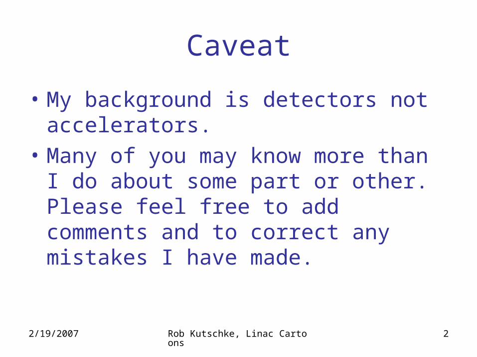
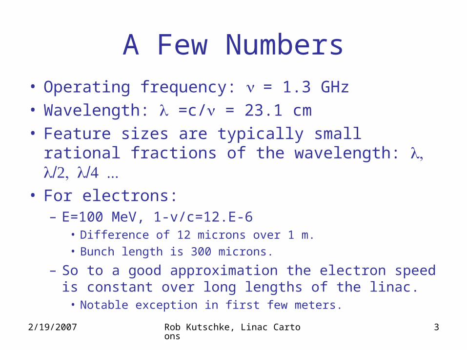
A Few Numbers• Operating frequency: = 1.3 GHz• Wavelength: =c/ = 23.1 cm• Feature sizes are typically small rational
fractions of the wavelength: • For electrons:
– E=100 MeV, 1-v/c=12.E-6• Difference of 12 microns over 1 m.• Bunch length is 300 microns.
– So to a good approximation the electron speed is constant over long lengths of the linac.
• Notable exception in first few meters.
2/19/2007 Rob Kutschke, Linac Cartoons 4
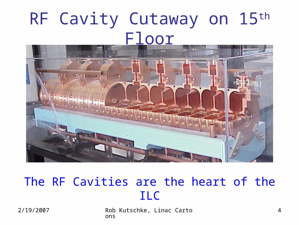
RF Cavity Cutaway on 15th Floor
The RF Cavities are the heart of the ILC
2/19/2007 Rob Kutschke, Linac Cartoons 5
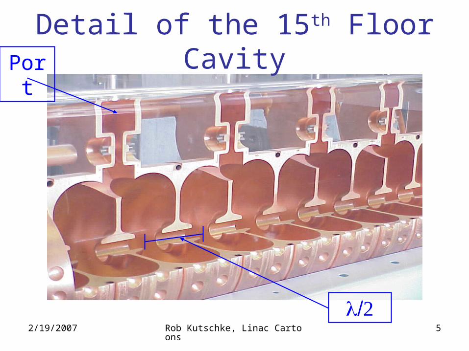
Detail of the 15th Floor Cavity
Port
2/19/2007 Rob Kutschke, Linac Cartoons 6
• RF energy enters via ports– ILC has only one port per 9 cell cavity (?).
• Energy bounces around inside the cavity cells. Bouncing waves interfere with each other.
• Shape designed to get standing wave interference pattern with the property that the on axis electric field is:– Parallel to the axis.– Oscillates in strength (+ and - ).
• Close to axis the transverse components are small.• Far from axis the field is complicated.• Q of ILC cavity needs to be 1010. High Q implies:
– Higher on axis field for a given input power at correct frequency.– Tighter demands on accuracy and stability of the input power.– Tight mechanical and material tolerances.
• Cavities can be tuned to respond to the correct frequency.
2/19/2007 Rob Kutschke, Linac Cartoons 7
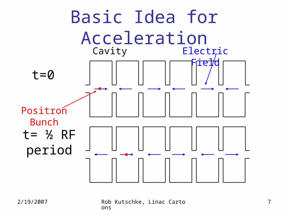
t= ½ RF period
t=0
Electric FieldCavity
Positron Bunch
Basic Idea for Acceleration
2/19/2007 Rob Kutschke, Linac Cartoons 8
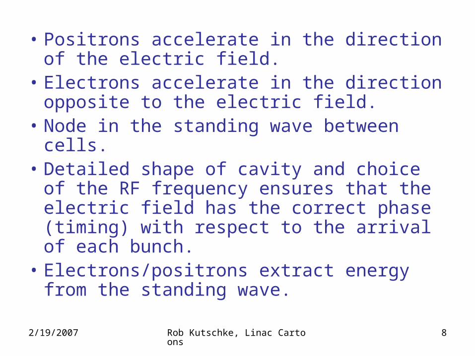
• Positrons accelerate in the direction of the electric field.
• Electrons accelerate in the direction opposite to the electric field.
• Node in the standing wave between cells.• Detailed shape of cavity and choice of the
RF frequency ensures that the electric field has the correct phase (timing) with respect to the arrival of each bunch.
• Electrons/positrons extract energy from the standing wave.
2/19/2007 Rob Kutschke, Linac Cartoons 9
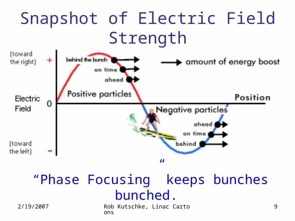
Snapshot of Electric Field Strength
“Phase Focusing” keeps bunches bunched.
2/19/2007 Rob Kutschke, Linac Cartoons 10
• Operate close to max field strength:– Gives maximum acceleration
• But not too close:– No phase focusing exactly at max.– Actually defocuses if bunch straddles max.
• High frequency, short bunch length and long accelerator length make it harder to precisely control the timing of the RF relative to the arrival of the bunch at every cell.
2/19/2007 Rob Kutschke, Linac Cartoons 11
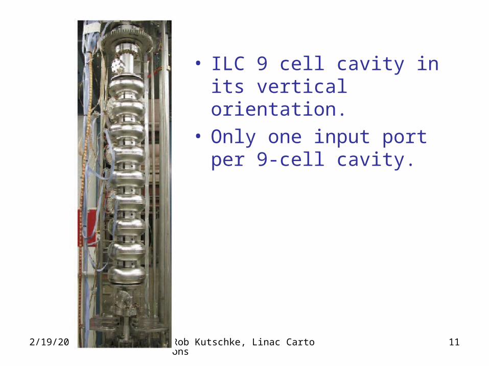
• ILC 9 cell cavity in its vertical orientation.
• Only one input port per 9-cell cavity.
2/19/2007 Rob Kutschke, Linac Cartoons 12
Why 9 Cells per Cavity?
• If too few cells/cavity the packing fraction is too small.– Need things like bellows between cavities to allow for
thermal expansion.– Other reasons?
• If too many cells/cavity:– Production yield issues. – Peak accelerating field drops with number of cells
( really another sort of yield issue ).– Other reasons? Approximation of constant speed
fails????
2/19/2007 Rob Kutschke, Linac Cartoons 13
What Are the Other Parts For?
• Delivering power to RF cavities.
• Corrections for imperfections.– Includes focusing of off-axis particles.
• Feedback and monitoring.
2/19/2007 Rob Kutschke, Linac Cartoons 14
Klystron
• A narrow band RF amplifier.• Phase of output waveform controlled by a
reference wave ( from low level RF ).• Amplitude of output frequency governed by
power delivered by the RF Modulator ( think of it as a power supply for the klystron ).
• More info: – http://en.wikipedia.org/wiki/Klystron– http://www2.slac.stanford.edu/vvc/accelerator.html
2/19/2007 Rob Kutschke, Linac Cartoons 15
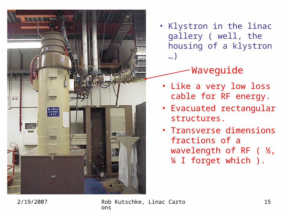
• Klystron in the linac gallery ( well, the housing of a klystron …)
Waveguide
• Like a very low loss cable for RF energy.
• Evacuated rectangular structures.
• Transverse dimensions fractions of a wavelength of RF ( ½, ¼ I forget which ).
2/19/2007 Rob Kutschke, Linac Cartoons 16
• Bunch extracts energy from the standing wave.• What happens if you put power into a cavity but
no bunch comes through?– Energy bounces around the cavity and comes back
out the wave guide.• Time scale (???).
– Need to protect klystron from reflected power• Circulator (recirculator, isolator … not sure of name ) directs
reflected energy to a load.
• Bunch does not remove 100% of the energy so some always bounces back. (Check this?).– Modulator should be programmed to supply less
energy if a small bunch is expected. • Or else input energy is just transported to dump. Wasteful.
– Is this controlled by low level RF?
2/19/2007 Rob Kutschke, Linac Cartoons 17
• What happens if you send an on axis beam down an unpowered cavity?– It creates a standing wave in the cavity ( which runs out
the waveguide if attached ).
• What about an off axis beam?– Creates higher order modes (HOM) in the cavity.
• Excites other patterns of standing waves at different frequencies.
• Need to get rid of this energy by putting a second port on the cavity (at a location that does not disturb the primary standing wave much ).
• Connect a waveguide to this other port and send the higher order mode energy to a load.
• Drum head example?
• Offaxis beam in powered cavity is the same.
2/19/2007 Rob Kutschke, Linac Cartoons 18
• Can use the HOM port for diagnostics.
• I vaguely recall the ILC design has three ports: main power input, HOM and diagnostics. Need to check.
• Can also check cavity performance with and without beam by measuring the reflected power.
• For the first few meters of the linac the electron speed is much less than c and special treatment is needed.
2/19/2007 Rob Kutschke, Linac Cartoons 19
Dewars, Cryostats, Cryomodules• Dewar:
– Vessel with vacuum insulation (thermos bottle).– Contents is not under vacuum; vacuum is in the walls.
• Cryostat:– A device used to maintain constant low temperature.– Usually two layers of dewars: liquid nitrogen layer
outside and liquid helium layer inside.• I guess ILC ones are like this (don’t really know).
• Cryomodule:– 3 cavities ( 9+9+8) cells enclosed in a single cryostat. – 8 cell cavity also holds some magnets
• Focusing, correcting??? Not sure.
2/19/2007 Rob Kutschke, Linac Cartoons 20
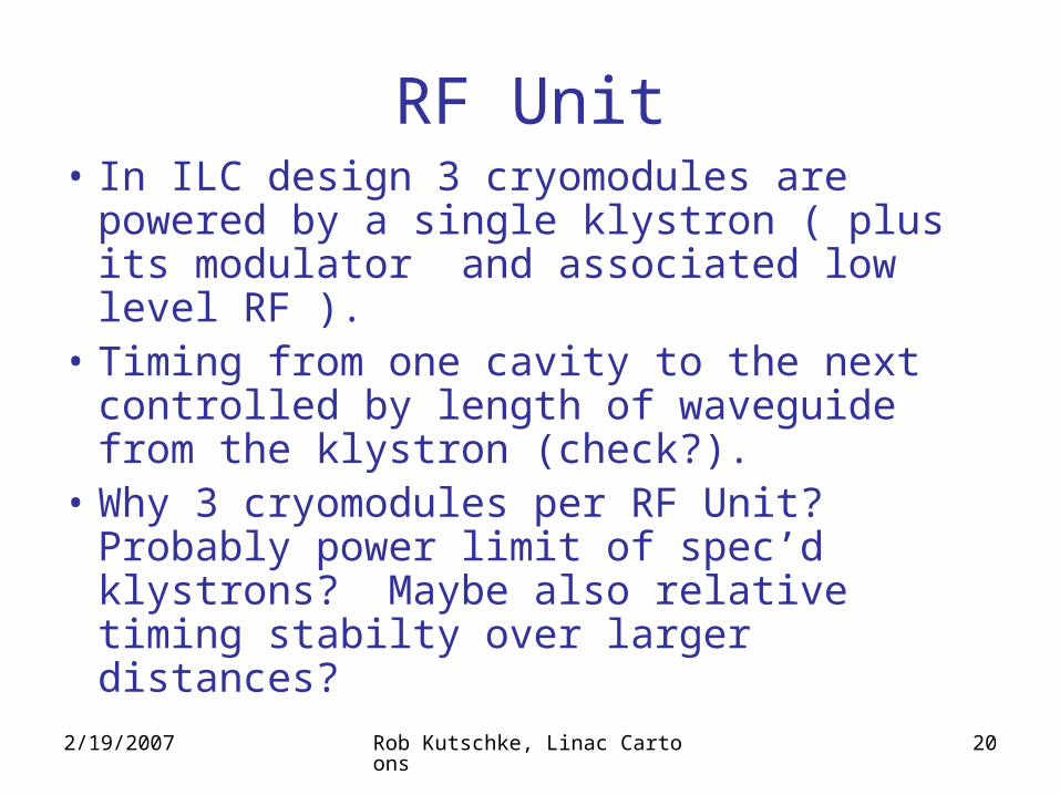
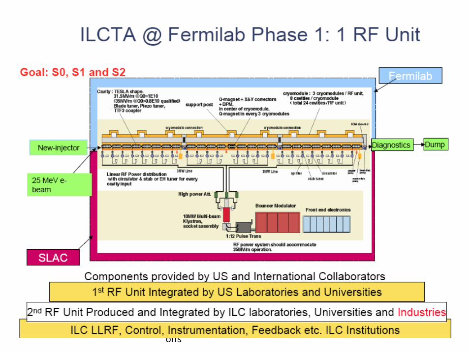
RF Unit• In ILC design 3 cryomodules are powered
by a single klystron ( plus its modulator and associated low level RF ).
• Timing from one cavity to the next controlled by length of waveguide from the klystron (check?).
• Why 3 cryomodules per RF Unit? Probably power limit of spec’d klystrons? Maybe also relative timing stabilty over larger distances?
2/19/2007 Rob Kutschke, Linac Cartoons 21
2/19/2007 Rob Kutschke, Linac Cartoons 22
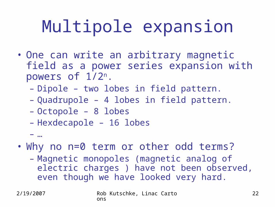
Multipole expansion
• One can write an arbitrary magnetic field as a power series expansion with powers of 1/2n.– Dipole – two lobes in field pattern.– Quadrupole – 4 lobes in field pattern.– Octopole – 8 lobes– Hexdecapole – 16 lobes– …
• Why no n=0 term or other odd terms?– Magnetic monopoles (magnetic analog of electric
charges ) have not been observed, even though we have looked very hard.
2/19/2007 Rob Kutschke, Linac Cartoons 23
Dipole Magnet – Old Style
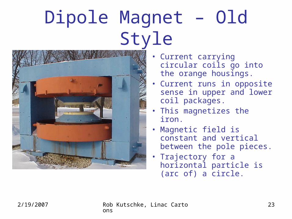
• Current carrying circular coils go into the orange housings.
• Current runs in opposite sense in upper and lower coil packages.
• This magnetizes the iron.• Magnetic field is constant
and vertical between the pole pieces.
• Trajectory for a horizontal particle is (arc of) a circle.
2/19/2007 Rob Kutschke, Linac Cartoons 24
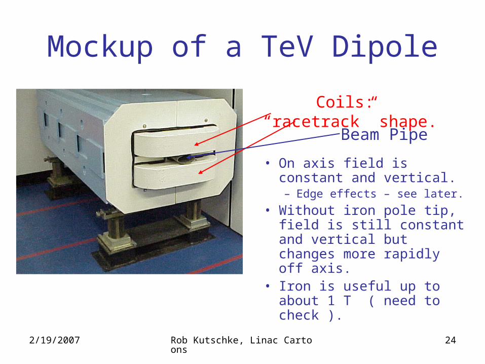
Mockup of a TeV Dipole
Coils: “racetrack” shape.
Beam Pipe
• On axis field is constant and vertical.– Edge effects – see later.
• Without iron pole tip, field is still constant and vertical but changes more rapidly off axis.
• Iron is useful up to about 1 T ( need to check ).
2/19/2007 Rob Kutschke, Linac Cartoons 25
Dipole Magnets• TeV magnets have iron, like the old magnet
shown a few pages back. – The shape of the field between the pole tips is
governed by the shape of the iron.– Can be sloppier about coil construction.
• For fields over about 1 Tesla, iron saturates.• To get stronger fields, just use coils without iron.
– Tougher construction tolerances for coils.– To get really strong fields you need very high
currents: use superconducting coils to keep losses low.
2/19/2007 Rob Kutschke, Linac Cartoons 26
Quadrupole Magnets• What happens if a particle is not traveling exactly along
the cavity axis, or if the axes of all cavities are not perfectly lined up.– Particle starts to drift transversely.
• Focused back to the beam axis by quads.– Four current loops.
• Quads focus (FO) in x and defocus (DO) in y ( or vise versa ). – Or pick any pair of orthogonal transverse coords.
• If a FODO pair have the correct separation there is net focusing in both planes.
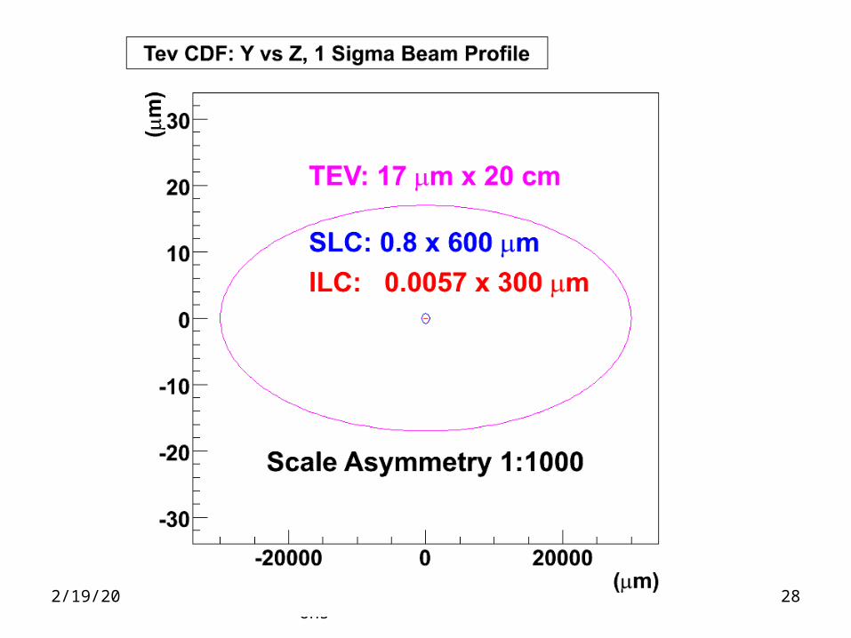
• During acceleration the beam is only focused enough to keep it in the “sweet spot” of the machine.– At IP the beam is tightly focused.
• Spot size times divergence is conserved.
2/19/2007 Rob Kutschke, Linac Cartoons 27
2/19/2007 Rob Kutschke, Linac Cartoons 28
2/19/2007 Rob Kutschke, Linac Cartoons 29
Corrector Magnets.• Dipoles and quads have end effects,
construction tolerances, materials defects …• These produce higher order multi-pole
components.• Need to have higher order magnets to correct for
the errors induced by these effects:– Sextupole– Octopole– Hexadecapole– …
• Positions of these magnets are fixed. To make the corrections, one varies the currents in them.
2/19/2007 Rob Kutschke, Linac Cartoons 30
Kicker Magnet• Magnet used to move particles from one
trajectory to another. Example: injection or extraction into MI, TeV, Booster …– Always a dipole?
• Magnet and associated power supply must have fast rise and fall times.– Do not want to disrupt leading and trailing bunches,
just the one you want.
• Often the bore needs to be wider than a typical magnet to accommodate the two trajectories.
2/19/2007 Rob Kutschke, Linac Cartoons 31
Making Positrons• The ILC will accelerate bunch trains of about 1 ms in
length, 5 times a second.– Duty cycle is about 1/200.
• During the off-cycle, electrons will be accelerated partway down the main linac and diverted to an undulator.– Static, period magnetic structure with very high magnetic field
gradients.– This wiggles the beam to radiate forward going photons.– Then you steer the electrons out of the way.
• Put a sheet of high-Z material (Pb?) in the path of the photons: produces electron-positron pairs ( plus junk).
• Keep the positrons and throw the rest away.– Do this with magnetic and electric fields.
2/19/2007 Rob Kutschke, Linac Cartoons 32
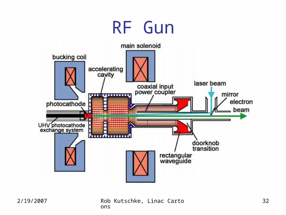
RF Gun
2/19/2007 Rob Kutschke, Linac Cartoons 33
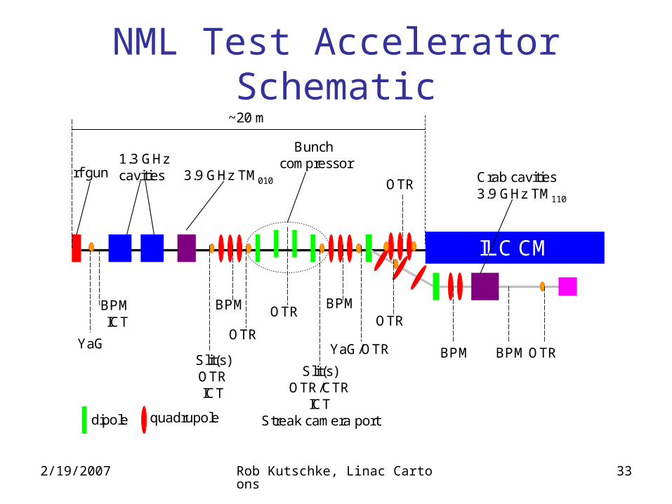
NML Test Accelerator Schematic
ILC CM
rf gun 3.9 GHz TM010
1.3 GHz cavities
Bunch compressor
Crab cavities3.9 GHz TM110
BPM BPM
Slit(s)OTRICT
OTR
Slit(s)OTR/CTR
ICTStreak camera port
YaG/OTR
OTR
BPM BPM
OTR
OTR
OTRYaG
BPM ICT
~20 m
dipole quadrupole
2/19/2007 Rob Kutschke, Linac Cartoons 34
Still to come
• Faraday Cup– Metal, cup-shaped electrode.– Used to measure ion currents. Think of a closed electric circuit
in which part of the path is not a wire but a stream of ions or electrons traveling in vacuum. The rest of the path is a more traditional electric circuit.
– Not sure how it is used here. I guess it is used to measure the electron current somewhere in the RF gun.
• Dark Current.• Magnetic Chicane bunch compressor.• Superconducting.
2/19/2007 Rob Kutschke, Linac Cartoons 35
Not Ready for Prime Time
2/19/2007 Rob Kutschke, Linac Cartoons 36
IQ Plot
• Could mean a few things. This is my guess.• Many observable things can be represented as a
complex number. – An RF signal at a fixed frequency has a magnitude and phase.
• I and Q are just the real and imaginary parts of the complex number. ( Sometimes the polar representation might be more useful).
• Language comes from the idea that you are measuring the amounts of some signal that are “In phase” and “in Quadrature” with a reference signal.
• Or it could refer to something totally different.
2/19/2007 Rob Kutschke, Linac Cartoons 37
More Trivia
• When a pulse of energy comes down wave guide from klystron, it induces currents in the walls of the cavity.
• These currents repell and attract each other ( known as Lorentz forces ).
• These forces distort the cavity.• Piezoelectric actuators are present to predistort
the cavity in the opposite direction so that the Lorentz force fixes the problem.