Embed Size (px)
Citation preview
1
Waveguide, cavities,
linear accelerators and RFQs
Lars Hjorth Præstegaard
Aarhus University Hospital
Aarhus University Hospital, Århus Sygehus
Outline
• Waveguides
• Cavities
• Linear accelerators (linacs)
– Accelerating structures
– Traveling and standing wave acceleration
– Longitudinal dynamics
– Beam loading
• RFQ linear accelerator
2
Waveguides
Aarhus University Hospital, Århus Sygehus
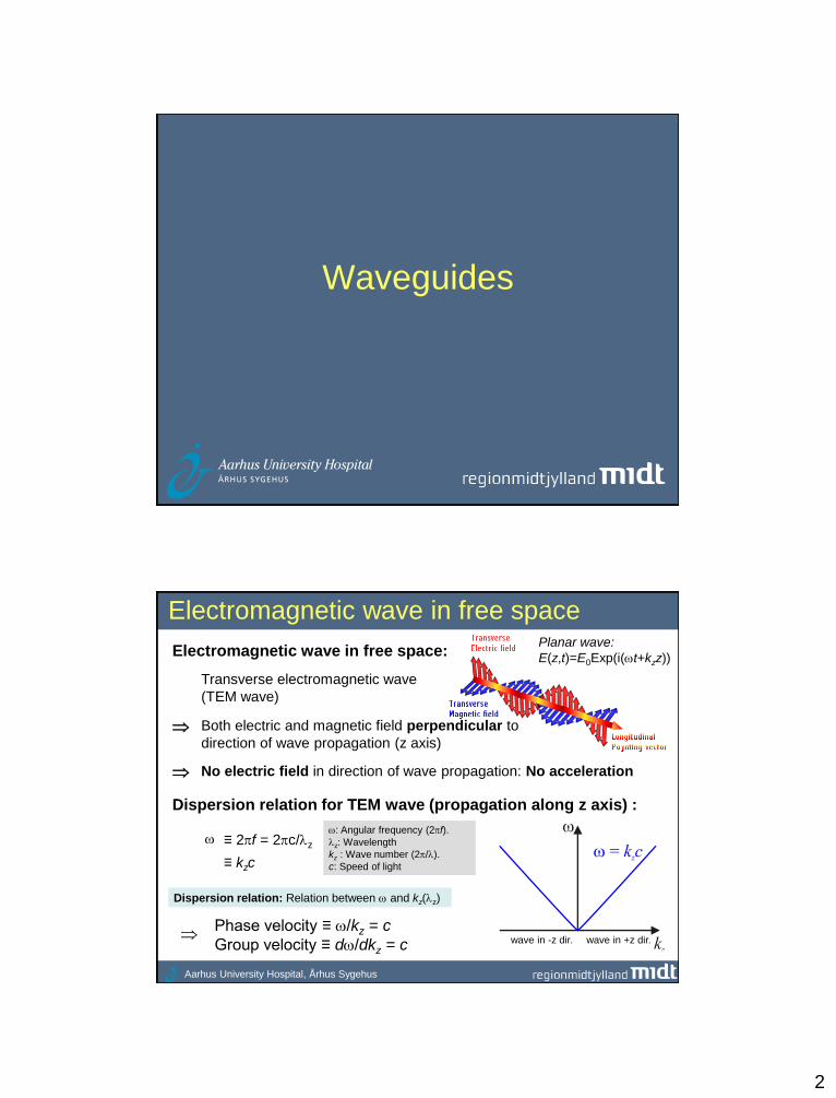
Electromagnetic wave in free space
Electromagnetic wave in free space:
Transverse electromagnetic wave
(TEM wave)
No electric field in direction of wave propagation: No acceleration
Both electric and magnetic field perpendicular to
direction of wave propagation (z axis)
: Angular frequency (2f).
z: Wavelength
kz : Wave number (2/).
c: Speed of light
Dispersion relation for TEM wave (propagation along z axis) :
Phase velocity ≡ /kz = c
Group velocity ≡ d/dkz = c
≡ 2f = 2c/z
≡ kzc
Dispersion relation: Relation between and kz(z)
Planar wave:
E(z,t)=E0Exp(i(t+kzz))
wave in +z dir. wave in -z dir.

3
Aarhus University Hospital, Århus Sygehus
z
z
Waveguide: Boundary conditions
Wave propagation
in +z direction
Solutions with a longitudinal field component must
be present in a waveguide (internal reflection)
Maxwell + boundary conditions No TEM wave in hollow waveguide
n
Conductor boundary conditions:
Conductor = equipotential: Ez=0
Conductor skin depth << : Bz/n=0
Aarhus University Hospital, Århus Sygehus
Waveguide: Solutions of wave equation
Wave equation for EZ (see appendix):
0,01
2
2
2
surfacezz EEtc
0,01
2
2
2
surface
zz
n
BB
tc
TE solution (Ez=0) exist:
Not suited for particle
acceleration
Wave equation for Bz:
TM solution (Bz=0) exist:
Suited for particle
acceleration
n TM: Transverse magnetic
TE: Transverse electric
From Ez and Bz, E and B
can easily be determined

4
Aarhus University Hospital, Århus Sygehus
Waveguide: Disp. relation for TM wave
Ansatz: zkωti
zzzex,yEr,tE
Oscillation with angular frequency
Propagation in +z direction
Wavelengthz=2/kz()
Physical field: Real component
yxEc
kyxE zzzt ,,
2
22
TM eigenvalue equation:
Ansatz
+ TM wave equation
Dispersion relation for TM
waveguide modes:
22
,2
2
znc kkc
Generator
frequency
Free space
solution
wave in +z dir. wave in -z dir.
No wave propagation below cut-
off frequency c,1 ≡ ckc,1 : Stopband
n'th eigenvalue (infinite number of
eigenvalues: waveguide modes)
n=1
n=2
n=3
kz
-kc,n2
2
2
2
2
yxtEz,surface=0
Aarhus University Hospital, Århus Sygehus
Waveguide: Phase and group velocity
Phase velocity and group velocity:
12
2
, z
nc
z k
kc
k
12
2
,
z
ncz
g
k
k
c
k
> c < c
Generator
frequency
Free space
solution
wave in +z dir. wave in -z dir.
Stopband
n=1
n=2
n=3
kz
5
Aarhus University Hospital, Århus Sygehus
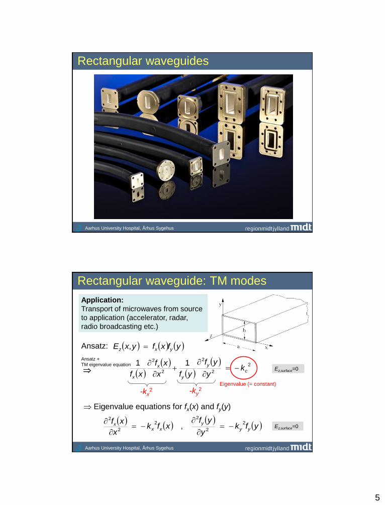
Rectangular waveguides
Aarhus University Hospital, Århus Sygehus
Rectangular waveguide: TM modes
Application:
Transport of microwaves from source
to application (accelerator, radar,
radio broadcasting etc.)
Ansatz: yfxfyxE yxz ,
Ansatz +
TM eigenvalue equation
2
2
2
2
2 11c
y
y
x
x
ky
yf
yfx
xf
xf
yfky
yfxfk
x
xfyy
y
xxx 2
2
22
2
2
,
Eigenvalue (= constant)
-kx2 -ky
2
Eigenvalue equations for fx(x) and fy(y)
Ez,surface=0
Ez,surface=0
6
Aarhus University Hospital, Århus Sygehus
22
222
b
n
a
mkkk yxmnc
,
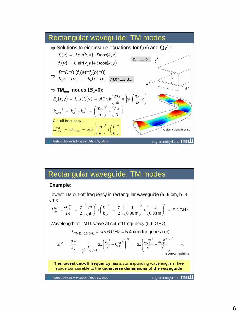
Rectangular waveguide: TM modes
Solutions to eigenvalue equations for fx(x) and fy(y) :
xkBxkAxf xxx cossin
ykDykCyf yyy cossin Ez,surface=0
B=D=0 (fx(a)=fy(b)=0)
kxa = m , kyb = n
TMnm modes (Bz=0):
Color: Strength of Ez
22
b
n
a
mcck mnc
TM
mnc ,,
m,n=1,2,3,..
y
b
nx
a
mACyfxfyxE yxz
sinsin,
Cut-off frequency:
Aarhus University Hospital, Århus Sygehus
Rectangular waveguide: TM modes
GHz .m .m .
,
, 65030
1
060
1
222
2222
11
11
c
b
n
a
mcf
TM
cTM
c
Example:
Lowest TM cut-off frequency in rectangular waveguide (a=6 cm, b=3
cm):
Wavelength of TM11 wave at cut-off frequnecy (5.6 GHz):
TM11, 5.6 GHz = c/5.6 GHz = 5.4 cm (for generator)
The lowest cut-off frequency has a corresponding wavelength in free
space comparable to the transverse dimensions of the waveguide
½
,,
½
,11 2
2
11
2
2
112
112
2
222
cck
ck
TM
c
TM
cTM
c
z
TM
22
2
2
znc kkc
,
(in waveguide)
7
Aarhus University Hospital, Århus Sygehus
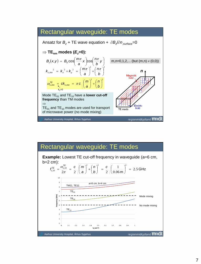
Rectangular waveguide: TE modes
TEnm modes (Ez=0):
Ansatz for Bz + TE wave equation + Bz/n,surface=0
n 22
222
b
n
a
mkkk yxmnc
,
y
b
nx
a
mByxBz
coscos, 0
22
b
n
a
mcck mnc
TE
mnc ,,
m,n=0,1,2,... (but (m,n) (0,0))
Mode TE01 and TE10 have a lower cut-off
frequency than TM modes
TE01 and TE10 modes are used for transport
of microwave power (no mode mixing)
kz=0
Aarhus University Hospital, Århus Sygehus
Rectangular waveguide: TE modes
GHz .m .
,
, 52060
1
222
222
10
10
c
b
n
a
mcf
TE
cTE
c
Example: Lowest TE cut-off frequency in waveguide (a=6 cm,
b=2 cm):
TE10
TE01
TM11, TE11 a=6 cm, b=4 cm
Mode mixing
No mode mixing
TE20

8
Aarhus University Hospital, Århus Sygehus
Rectangular waveguide: TE modes
1 possible mode
2 possible modes
Mode mixing in bend
(change of geometry)
a=6 cm, b=2 cm
a=6 cm, b=2 cm
Aarhus University Hospital, Århus Sygehus
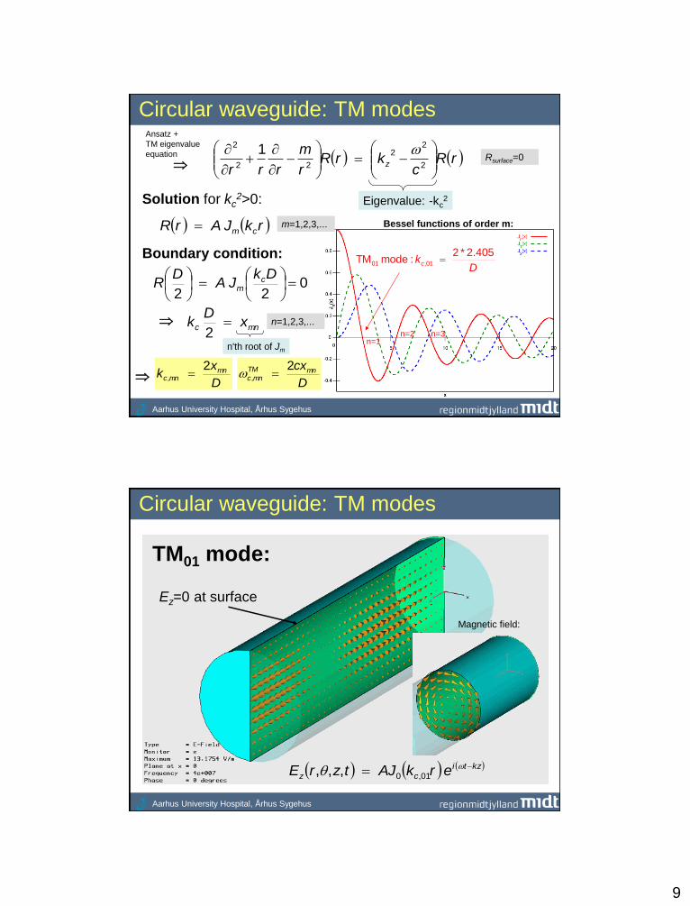
Circular waveguide: TM modes
Ansatz for circular waveguide:
TM eigenvalue equation in cylindrical coordinates:
D
z
m=0,1,2,.. (number of azimuthal oscillations) mrRrEz cos,
D: Diameter
Ez,surface=0
2
2
22
2 11
rrrrt
,,
2
22
rEc
krE zzzt
-kc,n2
9
Aarhus University Hospital, Århus Sygehus
mnc xD
k 2
Circular waveguide: TM modes
rRc
krRr
m
rrrz
2
22
22
2 1
Eigenvalue: -kc2 Solution for kc
2>0:
rkJArR cm
Boundary condition:
022
DkJA
DR c
m
n'th root of Jm
D
xk mn
mnc
2,
n=1 n=2
Dkc
405.2*2 :mode TM 01,01
n=3
Rsurface=0
D
cxmnTM
mnc
2,
n=1,2,3,...
Ansatz +
TM eigenvalue
equation
Bessel functions of order m: m=1,2,3,...
Aarhus University Hospital, Århus Sygehus
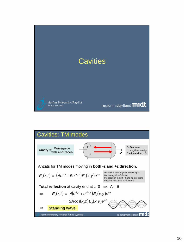
Circular waveguide: TM modes
Ez=0 at surface
kzti
cz erkAJtzrE 01,0,,,
TM01 mode:
Magnetic field:
10
Cavities
Aarhus University Hospital, Århus Sygehus
Cavities: TM modes
Anzats for TM modes moving in both -z and +z direction:
ti
z
zkzk
z eyxEBeAetE zz ,, r
Oscillation with angular frequency
Wavelengthz=2/kz()
Propagation in both -z and +z directions
Physical field: real component
Total reflection at cavity end at z=0 A = B
ti
z
zikzik
z eyxEeeAtE zz ,, r
ti
zz eyxEzkA ,cos2
Standing wave
D
z
l
Waveguide
with end faces Cavity ≡
D: Diameter
l: Length af cavity
Cavity end at z=0

11
Aarhus University Hospital, Århus Sygehus
Cavities: TM modes
Boundary condition at cavity ends (Et=0)
0sin,,,,,0,, ti
ztt elkyxCtlyxEtyxE
Requires some
derivation
Transverse electric field of standing wave:
ti
zt ezkyxCtzyxE sin,,,,
kzl = q q
lz
2
Only certain resonant frequencies are present in a cavity
Dispersion relation for cavity:
q=0,1,2,...
2
222
2
2
l
qk
cc
1. Also valid for TE mode, except that q=0 do not exist (Et=0)
2. Resonant frequency of q=0 mode is independent of length
of cavity
Aarhus University Hospital, Århus Sygehus
Cylindrical cavity: TM modes
D
z
l
Cylindrical cavity:
Preferred design for
acceleration of charged
particles)
2
222
2
222 2
l
q
D
xc
l
qkc mn
c
TM
mnq
Resonant frequencies of TM modes:
TM010 mode:
[cm] D
GHz .952201010
D
cxf TM
Note:
Wille specifies r≡c/fr=2c/r. This is
the generator wavelength
corresponding to resonant frequency
(different to the wavelength of the
wave in the cavity)
12
Aarhus University Hospital, Århus Sygehus
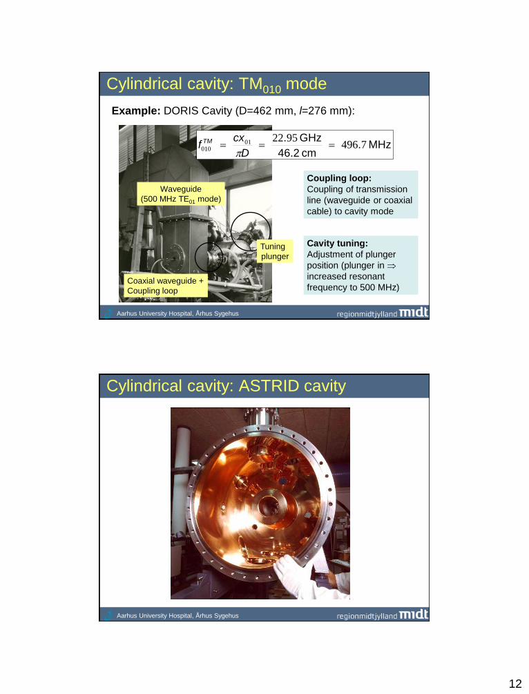
Cylindrical cavity: TM010 mode
Example: DORIS Cavity (D=462 mm, l=276 mm):
MHz .cm 46.2
GHz .7496
952201010
D
cxf TM
Tuning
plunger
Coupling loop:
Coupling of transmission
line (waveguide or coaxial
cable) to cavity mode
Cavity tuning:
Adjustment of plunger
position (plunger in
increased resonant
frequency to 500 MHz)
Waveguide
(500 MHz TE01 mode)
Coaxial waveguide +
Coupling loop
Aarhus University Hospital, Århus Sygehus
Cylindrical cavity: ASTRID cavity
13
Aarhus University Hospital, Århus Sygehus
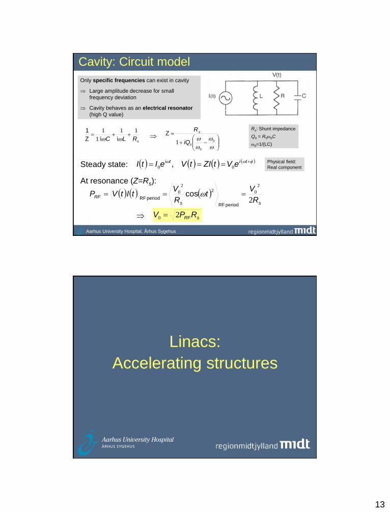
Cavity: Circuit model
Only specific frequencies can exist in cavity
Large amplitude decrease for small
frequency deviation
Cavity behaves as an electrical resonator
(high Q value)
sRLC
11
1
1
iiZ
1
0
0
01 iQ
RsZRs: Shunt impedance
Q0 = R00C
0=1/(LC)
Steady state:
ss
RFR
Vt
R
VtItVP
2
2
022
0
period RF
period RFcos
sRFRPV 20
titi eVtZItVeItI 00 ,
At resonance (Z=Rs):
Physical field:
Real component
Linacs:
Accelerating structures
14
Aarhus University Hospital, Århus Sygehus
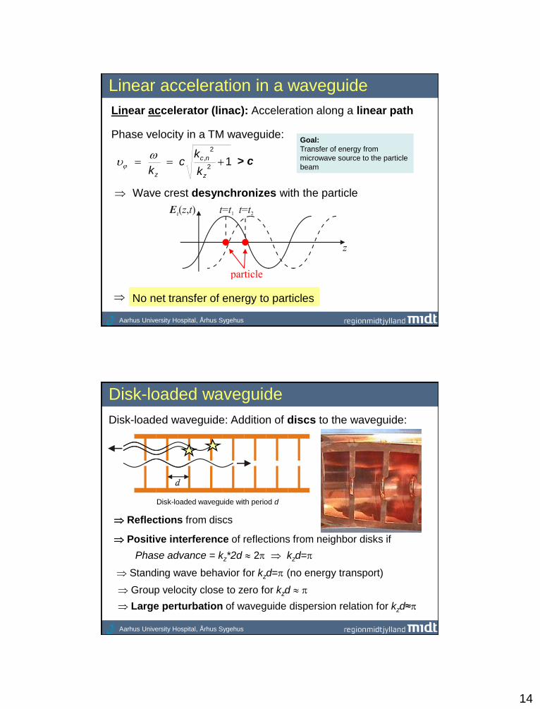
Linear acceleration in a waveguide
Phase velocity in a TM waveguide:
No net transfer of energy to particles
Wave crest desynchronizes with the particle
12
2
, z
nc
z k
kc
k
> c
Linear accelerator (linac): Acceleration along a linear path
Goal:
Transfer of energy from
microwave source to the particle
beam
Aarhus University Hospital, Århus Sygehus
Disk-loaded waveguide
Reflections from discs
Disk-loaded waveguide: Addition of discs to the waveguide:
Positive interference of reflections from neighbor disks if
Disk-loaded waveguide with period d
Phase advance = kz*2d 2 kzd=
Large perturbation of waveguide dispersion relation for kzd≈
Standing wave behavior for kzd= (no energy transport)
Group velocity close to zero for kzd
15
Aarhus University Hospital, Århus Sygehus
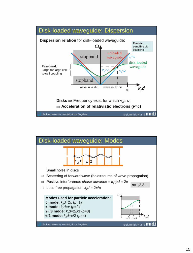
Disk-loaded waveguide: Dispersion
Dispersion relation for disk-loaded waveguide:
wave in +z dir. wave in -z dir.
Passband:
Large for large cell-
to-cell coupling
Electric
coupling via
beam iris
kzd
Disks Frequency exist for which = c
Acceleration of relativistic electrons (v=c)
Aarhus University Hospital, Århus Sygehus
Disk-loaded waveguide: Modes
Loss-free propagation: kzd = 2/p p=1,2,3,...
Modes used for particle acceleration:
0 mode: kzd=2 (p=1)
mode: kzd= (p=2)
2/3 mode: kzd=2/3 (p=3)
/2 mode: kzd=/2 (p=4)
Small holes in discs
Positive interference: phase advance = kz*pd = 2
p=2
Scattering of forward wave (hole=source of wave propagation)

16
Linacs:
Traveling wave (TW)
acceleration
Aarhus University Hospital, Århus Sygehus
Traveling wave (TW) acceleration
• Disk-loaded waveguide (slowed-down wave)
• TM wave and beam travels synchronous
• Input of RF power at first cell
• Output of RF power at last cell
• Injection of beam along axis of waveguide
RF load
Beam source
Resistive loss in walls
+ Energy transfer to beam
Reduction of microwave
power along waveguide
RF power in
17
Aarhus University Hospital, Århus Sygehus
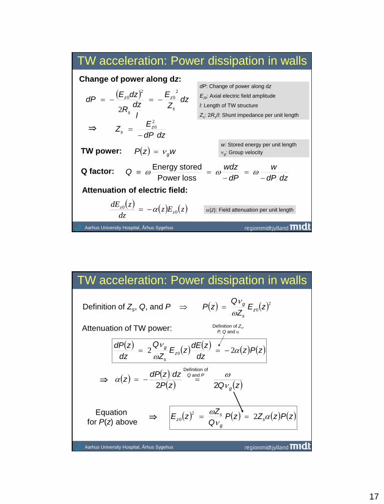
TW acceleration: Power dissipation in walls
Change of power along dz: dP: Change of power along dz
Ez0: Axial electric field amplitude
l: Length of TW structure
Zs: 2Rs/l: Shunt impedance per unit length
TW power:
dzdP
w
dP
wdzQ
loss Power
storedEnergy
wzP g
Q factor:
w: Stored energy per unit length
g: Group velocity
(z): Field attenuation per unit length
Attenuation of electric field:
zEz
dz
zdEz
z0
0
dz
Z
E
l
dzR
dzEdP
s
z
s
z
2
0
2
0
2
dzdP
EZ z
s
2
0
Aarhus University Hospital, Århus Sygehus
TW acceleration: Power dissipation in walls
Definition of Zs, Q, and P 20 zEZ
QzP z
s
g
zQzP
dzzdPz
g
22
Attenuation of TW power:
zPzdz
zdEzE
Z
Q
dz
zdPz
s
g
22 0
Definition of
Q and P
zPzZzPQ
ZzE s
g
sz
2
2
0 Equation
for P(z) above
Definition of Zs,
P, Q and

18
Aarhus University Hospital, Århus Sygehus
l
elqEdzeEqW
l
z
l
z
z
1
00 0
0
0
TW acceleration: Constant impedance
Constant impedance accelerating structure:
Uniform cell geometry
Q, Zs, g and do not depend on z
z
z
z
eE
zE
00
0
Energy gain for synchronous particle at wave crest:
l: Length of TW structure
Maximum of K (l=1.26):
Ez0(l) = 0.28Ez0(0) , P(l) = 0.08 P(0) (remaining power in load)
Low l: High power loss in load
High l: High power dissipation to walls
Tuning of K by changing g (disk aperture)
Importance of shunt impedance K (typically K≈0.8)
lPZql
es
l
01
2
K = 0.903
Equation
for Ez02
Aarhus University Hospital, Århus Sygehus
TW acceleration: Constant gradient
Constant gradient accelerating structure:
Ez0 does not depend on z (change of structure geometry):
• g and depends on z (sensitive to structure geometry)
• Q and Zs=Ez02/(-dP/dz) do not depend on z (approximately correct)
dP(z)/dz = constant z
l
PlPPzP
00
llP
P
dzzzP
zdP
00
2
Use of equation for attenuation of TW power:
zPz
dz
zdP2
l
dzzePlP0
2 ,0
19
Aarhus University Hospital, Århus Sygehus
TW acceleration: Constant gradient
Energy gain for synchronous particle at wave crest:
lqEdzEqW z
l
z 00 0
0
0 Tuning of K by changing g (disk aperture)
Importance of shunt impedance
22
0 10 e
l
PZ
dz
zdPZzE s
sz
Maximum of K (=):
21
0 el
P
dz
zdP
2110 e
l
zPzP
K (typically K≈0.8)
K = 1
lPZeq s 01 2
Expression
for Zs
Ez0(l) = P(l) = 0 (infinite filling time as g=0)
Aarhus University Hospital, Århus Sygehus
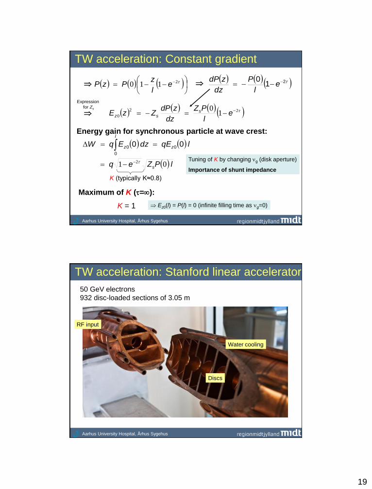
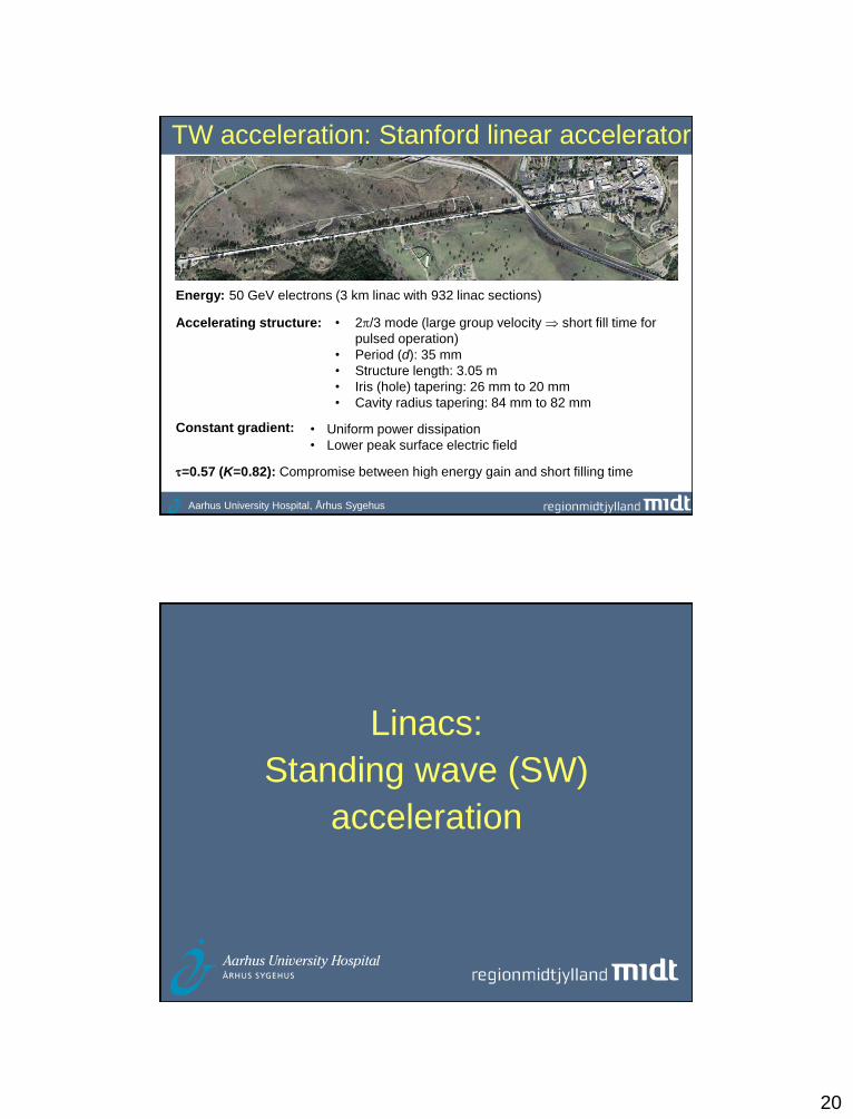
TW acceleration: Stanford linear accelerator
50 GeV electrons
932 disc-loaded sections of 3.05 m
Water cooling
RF input
Discs
20
Aarhus University Hospital, Århus Sygehus
TW acceleration: Stanford linear accelerator
Constant gradient:
Energy: 50 GeV electrons (3 km linac with 932 linac sections)
• Uniform power dissipation
• Lower peak surface electric field
Accelerating structure: • 2/3 mode (large group velocity short fill time for
pulsed operation)
• Period (d): 35 mm
• Structure length: 3.05 m
• Iris (hole) tapering: 26 mm to 20 mm
• Cavity radius tapering: 84 mm to 82 mm
=0.57 (K=0.82): Compromise between high energy gain and short filling time
Linacs:
Standing wave (SW)
acceleration
21
Aarhus University Hospital, Århus Sygehus
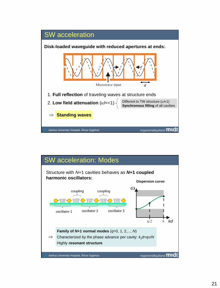
SW acceleration
1. Full reflection of traveling waves at structure ends
Disk-loaded waveguide with reduced apertures at ends:
Standing waves
Different to TW structure (l1)
Synchronous filling of all cavities 2. Low field attenuation (l<<1)
d
Aarhus University Hospital, Århus Sygehus
SW acceleration: Modes
Family of N+1 normal modes (q=0, 1, 2,..., N)
Characterized by the phase advance per cavity: kzd=q/N
Highly resonant structure
Structure with N+1 cavities behaves as N+1 coupled
harmonic oscillators:
oscillator 1 oscillator 2 oscillator 3
coupling coupling
Dispersion curve:
kd
22
Aarhus University Hospital, Århus Sygehus
0 1 2 3 4 5 6
q=3 (pi/2 mode)
q=4 (2*pi/3 mode)
q=6 (pi mode)
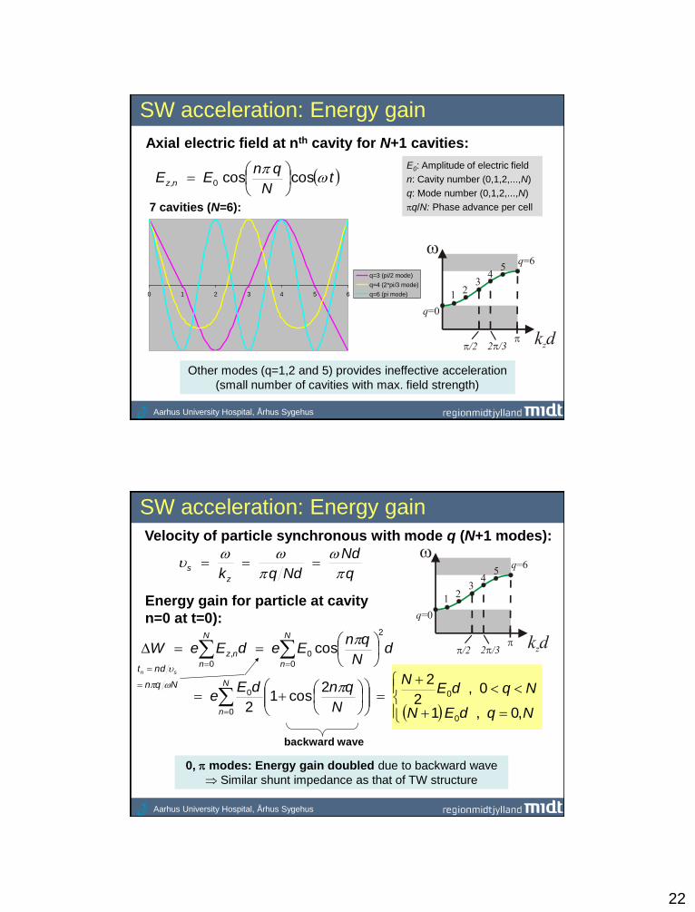
SW acceleration: Energy gain
tN
qnEE nz
coscos0,
Axial electric field at nth cavity for N+1 cavities:
E0: Amplitude of electric field
n: Cavity number (0,1,2,...,N)
q: Mode number (0,1,2,...,N)
q/N: Phase advance per cell 7 cavities (N=6):
Other modes (q=1,2 and 5) provides ineffective acceleration
(small number of cavities with max. field strength)
Aarhus University Hospital, Århus Sygehus
SW acceleration: Energy gain
Velocity of particle synchronous with mode q (N+1 modes):
q
Nd
Ndqkz
s
Energy gain for particle at cavity
n=0 at t=0):
N
n
N
n
nz dN
qnEedEeW
0
2
0
0
, cos
backward wave
0, modes: Energy gain doubled due to backward wave
Similar shunt impedance as that of TW structure
Nqn
ndt sn
NqdEN
NqdEN
N
qndEe
N
n ,0,1
0,2
22
cos12
0
0
0
0
23
Aarhus University Hospital, Århus Sygehus
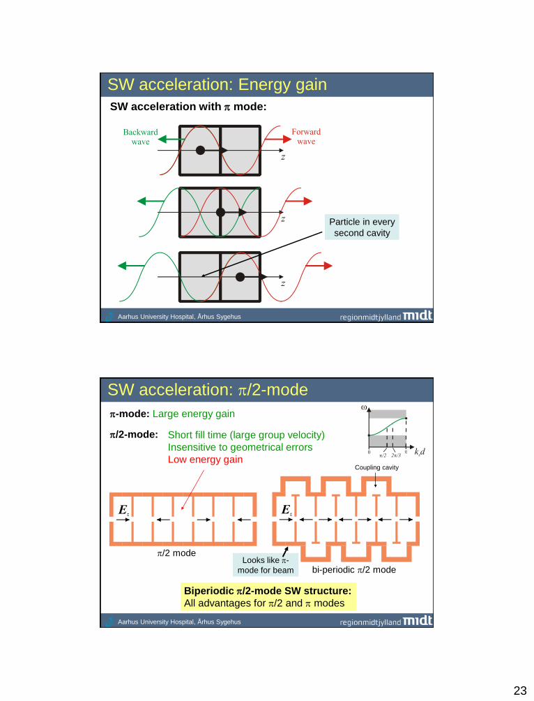
SW acceleration: Energy gain
SW acceleration with mode:
Particle in every
second cavity
Aarhus University Hospital, Århus Sygehus
SW acceleration: /2-mode
-mode: Large energy gain
Short fill time (large group velocity)
Insensitive to geometrical errors
Low energy gain
/2-mode:
/2 mode
bi-periodic /2 mode
Coupling cavity
Biperiodic /2-mode SW structure:
All advantages for /2 and modes
Looks like -
mode for beam
24
Aarhus University Hospital, Århus Sygehus
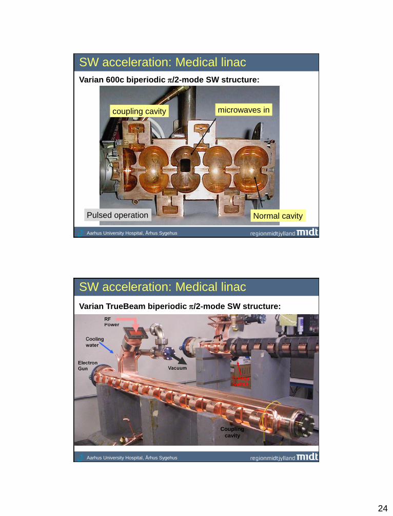
SW acceleration: Medical linac
Varian 600c biperiodic /2-mode SW structure:
microwaves in coupling cavity
Normal cavity Pulsed operation
Aarhus University Hospital, Århus Sygehus
SW acceleration: Medical linac
Varian TrueBeam biperiodic /2-mode SW structure:
Coupling
cavity
25
Aarhus University Hospital, Århus Sygehus
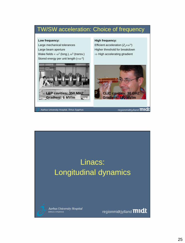
TW/SW acceleration: Choice of frequency
Low frequency:
Large mechanical tolerances
Large beam aperture
Wake fields 2 (long.), 3 (transv.)
Stored energy per unit length (-2)
High frequency:
Efficient acceleration (Zs½)
Higher threshold for breakdown
High accelerating gtradient
LEP cavities: 350 MHZ
Gradient: 6 MV/m
CLIC cavities: 30 GHZ
Gradient: 150 MV/m
Linacs:
Longitudinal dynamics
26
Aarhus University Hospital, Århus Sygehus
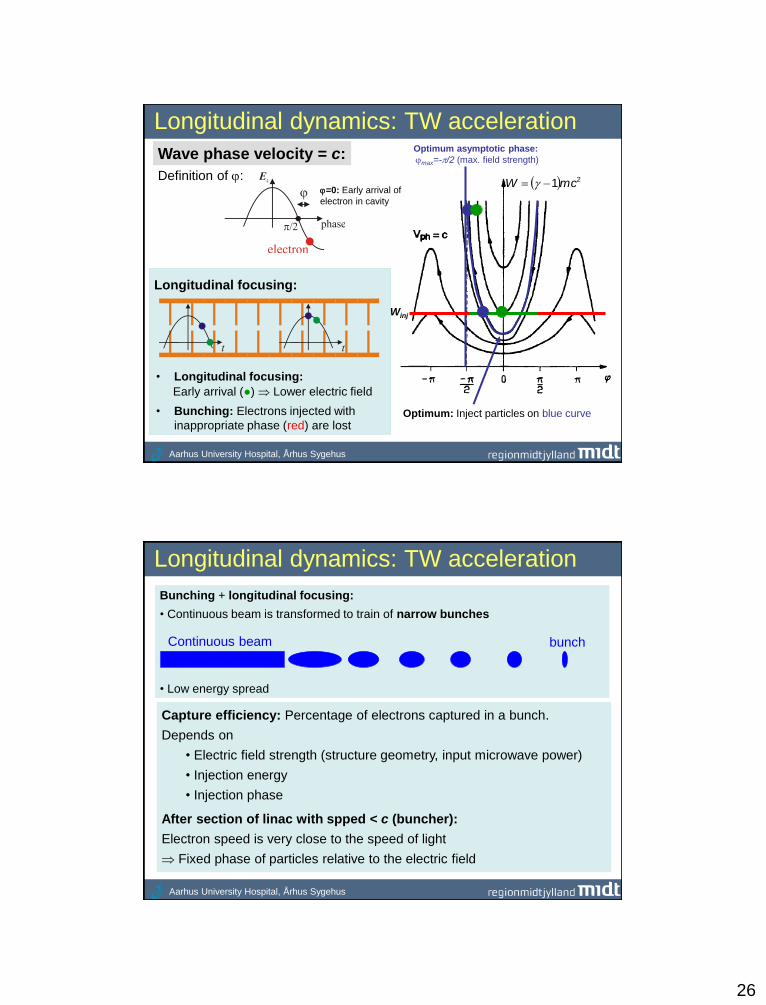
Longitudinal dynamics: TW acceleration
21mcW
Optimum: Inject particles on blue curve
Wave phase velocity = c:
Winj
Definition of :
Longitudinal focusing:
• Longitudinal focusing:
• Bunching: Electrons injected with
inappropriate phase (red) are lost
=0: Early arrival of
electron in cavity
Optimum asymptotic phase:
max=-/2 (max. field strength)
Early arrival (●) Lower electric field
Aarhus University Hospital, Århus Sygehus
Longitudinal dynamics: TW acceleration
Bunching + longitudinal focusing:
• Continuous beam is transformed to train of narrow bunches
• Low energy spread
Continuous beam bunch
Capture efficiency: Percentage of electrons captured in a bunch.
Depends on
• Electric field strength (structure geometry, input microwave power)
• Injection energy
• Injection phase
After section of linac with spped < c (buncher):
Electron speed is very close to the speed of light
Fixed phase of particles relative to the electric field
27
Linacs:
Beam loading
Aarhus University Hospital, Århus Sygehus
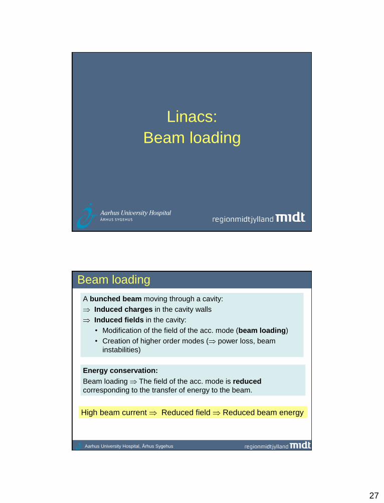
Beam loading
A bunched beam moving through a cavity:
Induced charges in the cavity walls
Induced fields in the cavity:
• Modification of the field of the acc. mode (beam loading)
• Creation of higher order modes ( power loss, beam
instabilities)
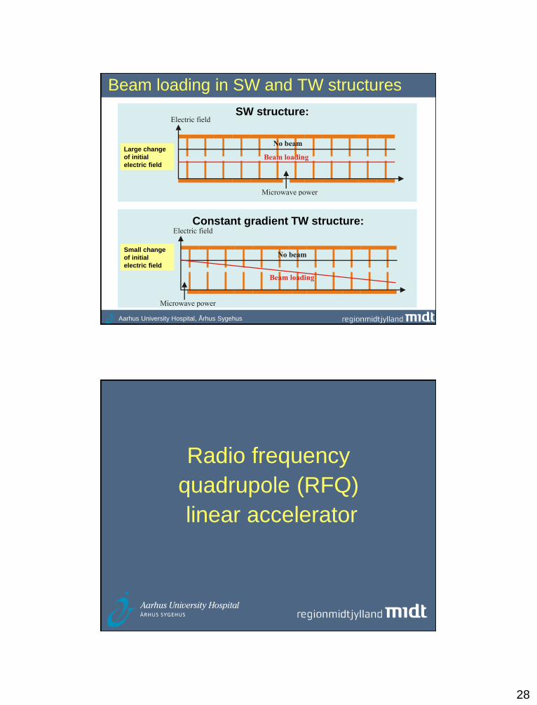
Energy conservation:
Beam loading The field of the acc. mode is reduced
corresponding to the transfer of energy to the beam.
High beam current Reduced field Reduced beam energy
28
Aarhus University Hospital, Århus Sygehus
Beam loading in SW and TW structures
SW structure:
Constant gradient TW structure:
Small change
of initial
electric field
Large change
of initial
electric field
Radio frequency
quadrupole (RFQ)
linear accelerator
29
Aarhus University Hospital, Århus Sygehus
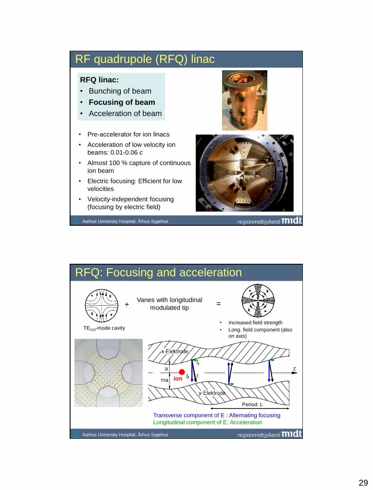
RF quadrupole (RFQ) linac
RFQ linac:
• Bunching of beam
• Focusing of beam
• Acceleration of beam
• Pre-accelerator for ion linacs
• Acceleration of low velocity ion
beams: 0.01-0.06 c
• Almost 100 % capture of continuous
ion beam
• Electric focusing: Efficient for low
velocities
• Velocity-independent focusing
(focusing by electric field)
Aarhus University Hospital, Århus Sygehus
RFQ: Focusing and acceleration
Transverse component of E : Alternating focusing
Longitudinal component of E: Acceleration
ion
Period: L
Vanes with longitudinal
modulated tip
TE210-mode cavity • Increased field strength
• Long. field component (also
on axis)
+ =
30
Aarhus University Hospital, Århus Sygehus
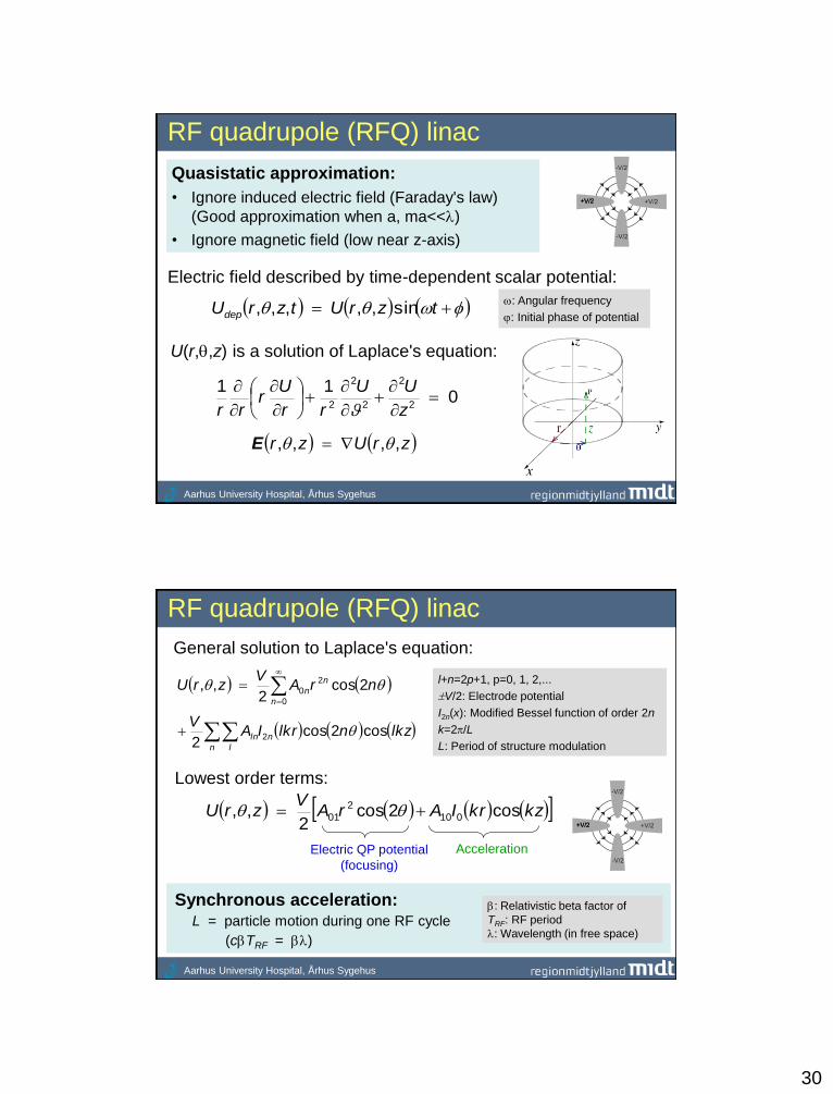
RF quadrupole (RFQ) linac
Quasistatic approximation:
• Ignore induced electric field (Faraday's law)
(Good approximation when a, ma<<)
• Ignore magnetic field (low near z-axis)
011
2
2
2
2
2
z
UU
rr
Ur
rr
: Angular frequency
: Initial phase of potential tzrUtzrUdep sin,,,,,
Electric field described by time-dependent scalar potential:
U(r,,z) is a solution of Laplace's equation:
zrUzr ,,,, E
Aarhus University Hospital, Århus Sygehus
RF quadrupole (RFQ) linac
General solution to Laplace's equation:
n l
nln
n
n
n
lkznlkrIAV
nrAV
zrU
cos2cos2
2cos2
,,
2
0
2
0
l+n=2p+1, p=0, 1, 2,...
V/2: Electrode potential
I2n(x): Modified Bessel function of order 2n
k=2/L
L: Period of structure modulation
Lowest order terms:
kzkrIArAV
zrU cos2cos2
,, 010
2
01
Electric QP potential
(focusing)
Acceleration
: Relativistic beta factor of
TRF: RF period
: Wavelength (in free space)
Synchronous acceleration: L = particle motion during one RF cycle
(cTRF = )

31
Aarhus University Hospital, Århus Sygehus
RF quadrupole (RFQ) linac
Boundary condition on electrode:
2
2,0,0,0,V
maUaU
period=L=
mkaIkaIm
mA
00
2
2
10
1
2010201 1
1
akaIA
aA
Large m: Large acceleration
Small a: Large focusing
Focusing
Acceleration
+V/2
Aarhus University Hospital, Århus Sygehus
RF quadrupole (RFQ) linac
Electric field components:
kzkrIkAV
z
UE
rVAU
rE
kzkrIkArAV
r
UE
z
r
sin2
2sin1
cos2cos22
010
01
11001
Acceleration
(also on axis as I0(0)=1)
32
More examples
Aarhus University Hospital, Århus Sygehus
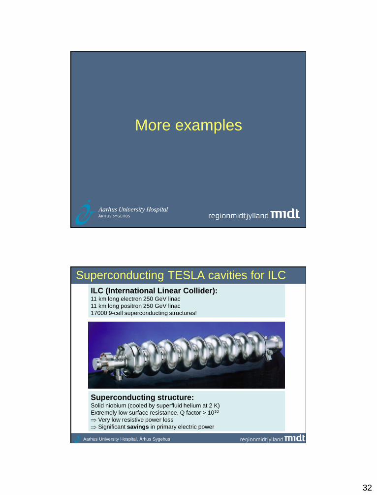
Superconducting TESLA cavities for ILC
Superconducting structure: Solid niobium (cooled by superfluid helium at 2 K)
Extremely low surface resistance, Q factor > 1010
Very low resistive power loss
Significant savings in primary electric power
ILC (International Linear Collider): 11 km long electron 250 GeV linac
11 km long positron 250 GeV linac
17000 9-cell superconducting structures!
33
Aarhus University Hospital, Århus Sygehus
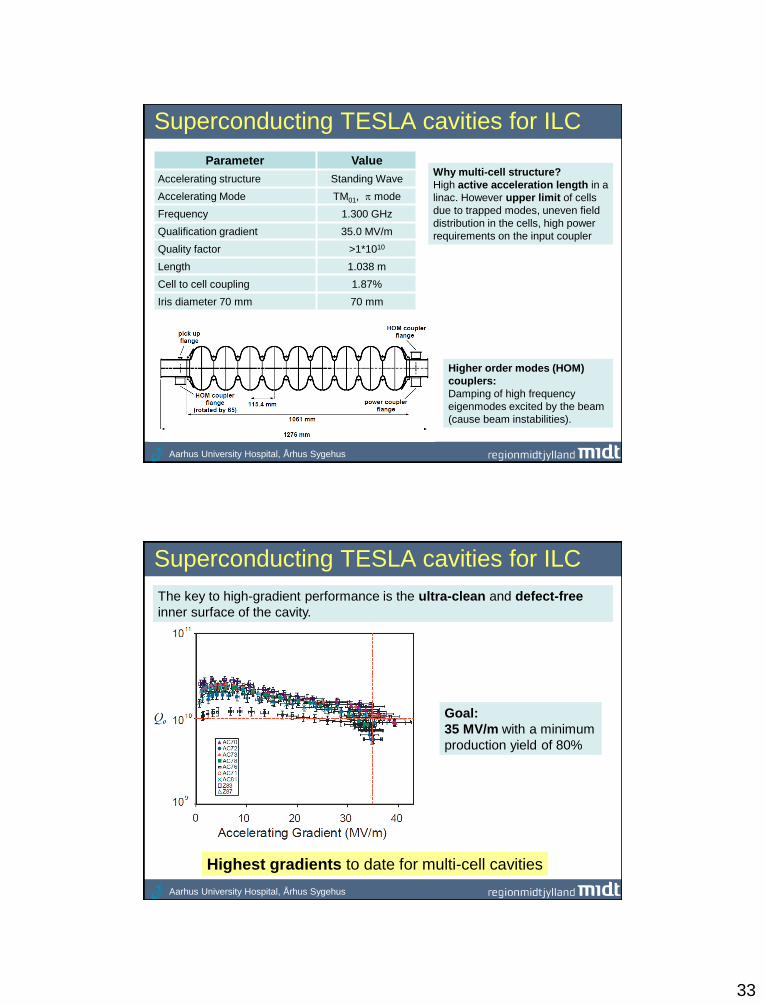
Superconducting TESLA cavities for ILC
Higher order modes (HOM)
couplers:
Damping of high frequency
eigenmodes excited by the beam
(cause beam instabilities).
Parameter Value
Accelerating structure Standing Wave
Accelerating Mode TM01, mode
Frequency 1.300 GHz
Qualification gradient 35.0 MV/m
Quality factor >1*1010
Length 1.038 m
Cell to cell coupling 1.87%
Iris diameter 70 mm 70 mm
Why multi-cell structure?
High active acceleration length in a
linac. However upper limit of cells
due to trapped modes, uneven field
distribution in the cells, high power
requirements on the input coupler
Aarhus University Hospital, Århus Sygehus
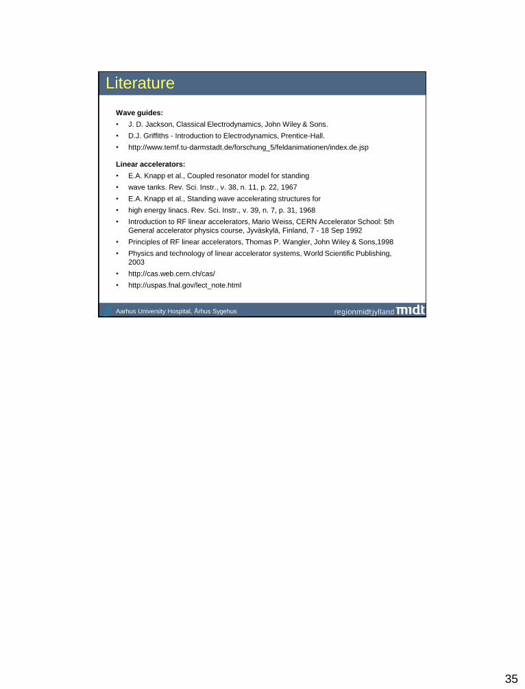
Superconducting TESLA cavities for ILC
The key to high-gradient performance is the ultra-clean and defect-free
inner surface of the cavity.
Highest gradients to date for multi-cell cavities
Goal:
35 MV/m with a minimum
production yield of 80%

34
Appendix
Aarhus University Hospital, Århus Sygehus
01
0
2
2
2
EBE
BEEB
E
tct
tt
Maxwell's equations without any sources:
Wave equation
0 E
t
BE
0 B
tc
EB
2
1
01
2
2
2
B
tcWave equation for magnetic field:
Wave equation for electric field:
0 E
t
BE
tc
EB
2
1Laplace operator
2
2
2
2
2
2
zyxAAA ,
35
Aarhus University Hospital, Århus Sygehus
Literature
Wave guides:
• J. D. Jackson, Classical Electrodynamics, John Wiley & Sons.
• D.J. Griffiths - Introduction to Electrodynamics, Prentice-Hall.
• http://www.temf.tu-darmstadt.de/forschung_5/feldanimationen/index.de.jsp
Linear accelerators:
• E.A. Knapp et al., Coupled resonator model for standing
• wave tanks. Rev. Sci. Instr., v. 38, n. 11, p. 22, 1967
• E.A. Knapp et al., Standing wave accelerating structures for
• high energy linacs. Rev. Sci. Instr., v. 39, n. 7, p. 31, 1968
• Introduction to RF linear accelerators, Mario Weiss, CERN Accelerator School: 5th
General accelerator physics course, Jyväskylä, Finland, 7 - 18 Sep 1992
• Principles of RF linear accelerators, Thomas P. Wangler, John Wiley & Sons,1998
• Physics and technology of linear accelerator systems, World Scientific Publishing,
2003
• http://cas.web.cern.ch/cas/
• http://uspas.fnal.gov/lect_note.html

![arXiv:1710.11546v1 [physics.app-ph] 31 Oct 2017 · Experimental observation of a large, low frequency Lamb band gap induced by periodic cross-like cavities in a polymer waveguide](https://img.pdfslide.us/doc/110x75/5b92e2c109d3f232708cb5dd/arxiv171011546v1-31-oct-2017-experimental-observation-of-a-large-low.jpg)