Embed Size (px)
Citation preview
Chalmers University of Technology
University of Gothenburg
Department of Computer Science and Engineering
Göteborg, Sweden, June 2010
A Battery Management Unit
Master of Science Thesis in the programmes Integrated Electronic System
Design & Secure and Dependable Computer Systems
HEIDI FISK
JOHAN LEIJGÅRD

The Author grants to Chalmers University of Technology and University of Gothenburg
the non-exclusive right to publish the Work electronically and in a non-commercial
purpose make it accessible on the Internet.
The Author warrants that he/she is the author of the Work, and warrants that the Work
does not contain text, pictures or other material that violates copyright law.
The Author shall, when transferring the rights of the Work to a third party (for example a
publisher or a company), acknowledge the third party about this agreement. If the Author
has signed a copyright agreement with a third party regarding the Work, the Author
warrants hereby that he/she has obtained any necessary permission from this third party to
let Chalmers University of Technology and University of Gothenburg store the Work
electronically and make it accessible on the Internet.
A Battery Management Unit
HEIDI FISK
JOHAN LEIJGÅRD
© HEIDI FISK, June 2010.
© JOHAN LEIJGÅRD, June 2010.
Examiner: JAN JONSSON
Chalmers University of Technology
University of Gothenburg
Department of Computer Science and Engineering
SE-412 96 Göteborg
Sweden
Telephone + 46 (0)31-772 1000
Department of Computer Science and Engineering
Göteborg, Sweden June 2010

Preface This thesis was done as a part of the Masters programme in Computer Science and Engineering
at Chalmers University of Technology.
We would like to thank QRTECH for giving us the opportunity to work in this exciting field.
Special thanks to our project supervisor at QRTECH, Linus Lundin, for all his guidance and
support. We would also like to thank Texas Instruments and the group working on the
bq76PL537 for all their help and ABATEL, our supplier and sponsor of the battery cells. We are
also grateful for the feedback on the thesis from our examiner Jan Jonsson.
And last, but not least, a big thanks to friends and family for their support.

Abstract Emissions from vehicles and decreasing oil resources are pressing matters in today’s society.
Electric vehicles are considered, by some, to be the solution to those problems. For years the
available batteries have been too heavy and inefficient to be used in commercial electric
vehicles. This thesis considers a new cell technology, LiFePO4, which was investigated and
implemented into a battery pack for a prototype electric go-cart. The LiFePO4 cells need to be
supervised by an efficient Battery Management Unit to function. The Battery Management
Unit implemented in this thesis was based on minimal hardware combined with a prototype
board for active cell balancing. The results show that it is possible to build such a lightweight
Battery Management Unit, but with the loss of accuracy in the system.
Keywords: State of charge, Battery Management, LiFePO4, Li-Ion, active cell balancing, electric
vehicle
Table of contents List of Abbreviations ...................................................................................................................... 1
1. Introduction............................................................................................................................... 2
1.1 Background.......................................................................................................................... 2
1.2 Battery Management Unit .................................................................................................. 3
1.3 Method ................................................................................................................................ 4
1.4 Scope ................................................................................................................................... 4
1.5 Limitations ........................................................................................................................... 4
1.6 Organization ........................................................................................................................ 5
2. Theory of batteries .................................................................................................................... 7
2.1 Battery construction............................................................................................................ 7
2.11 Primary and secondary cells .......................................................................................... 7
2.12 Cell structure ................................................................................................................. 7
2.13 Cell set-up ...................................................................................................................... 8
2.14 C rate ............................................................................................................................. 8
2.15 The LiFePO4 battery technology .................................................................................... 9
2.2 Batteries in EV ................................................................................................................... 11
2.21 Economics of EV .......................................................................................................... 11
2.22 Weight of batteries ..................................................................................................... 11
2.23 Temperature ............................................................................................................... 12
2.24 Power consumption in a car ........................................................................................ 13
2.3 Charging ............................................................................................................................ 14
2.31 Charging technologies ................................................................................................. 14
2.32 Effects of overcharging ................................................................................................ 15
2.33 Re-generative braking ................................................................................................. 15
2.4 Safety of batteries in electric vehicles............................................................................... 15
2.5 Environmental effects and recycling ................................................................................. 16
3. Theory of Battery Management Units .................................................................................... 17
3.1 State of Charge SOC .......................................................................................................... 17
3.11 Voltage measuring ...................................................................................................... 17
3.12 Coulomb measurement ............................................................................................... 19
3.13 Other possibilities to determine SOC .......................................................................... 19
3.14 SOC dependability ....................................................................................................... 19

3.2 Cell balancing .................................................................................................................... 19
3.21 Balancing in parallel and series connected cells ......................................................... 20
3.22 Passive cell balancing .................................................................................................. 20
3.23 Active cell balancing .................................................................................................... 21
3.24 Algorithms for cell balancing ....................................................................................... 23
3.3 Safety Functions in BMU ................................................................................................... 23
3.4 Reliability and fault tolerance ........................................................................................... 23
3.41 Battery pack ................................................................................................................ 24
3.42 BMU ............................................................................................................................. 25
3.43 Charging methods ....................................................................................................... 25
4. Project implementation .......................................................................................................... 26
4.1 Battery ............................................................................................................................... 26
4.11 Go-cart specification and battery requirements ......................................................... 26
4.12 Cell specification and design of battery pack .............................................................. 27
4.13 Charging method for the battery pack ........................................................................ 30
4.14 Extending the battery pack ......................................................................................... 30
4.2 System design .................................................................................................................... 30
4.21 Hardware design ......................................................................................................... 31
4.22 Communication ........................................................................................................... 34
4.3 BMU ................................................................................................................................... 36
4.31 SOC .............................................................................................................................. 36
4.32 Balancing ..................................................................................................................... 38
4.33 Safety ........................................................................................................................... 40
4.34 Extending the BMU ..................................................................................................... 40
4.4 Tools .................................................................................................................................. 41
5. Discussion ................................................................................................................................ 43
6. Conclusion ............................................................................................................................... 45
References ................................................................................................................................... 46
Appendix ........................................................................................................................................ I
A. UML description of the software ........................................................................................... I
B. Specification of the LiFePO4 cell ............................................................................................ II
C. List of battery companies ...................................................................................................... V
1
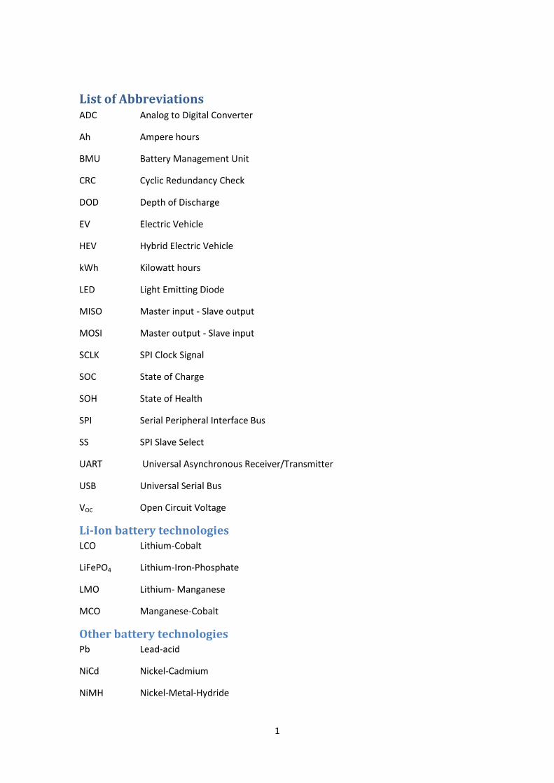
List of Abbreviations ADC Analog to Digital Converter
Ah Ampere hours
BMU Battery Management Unit
CRC Cyclic Redundancy Check
DOD Depth of Discharge
EV Electric Vehicle
HEV Hybrid Electric Vehicle
kWh Kilowatt hours
LED Light Emitting Diode
MISO Master input - Slave output
MOSI Master output - Slave input
SCLK SPI Clock Signal
SOC State of Charge
SOH State of Health
SPI Serial Peripheral Interface Bus
SS SPI Slave Select
UART Universal Asynchronous Receiver/Transmitter
USB Universal Serial Bus
VOC Open Circuit Voltage
Li-Ion battery technologies LCO Lithium-Cobalt
LiFePO4 Lithium-Iron-Phosphate
LMO Lithium- Manganese
MCO Manganese-Cobalt
Other battery technologies Pb Lead-acid
NiCd Nickel-Cadmium
NiMH Nickel-Metal-Hydride
2
1. Introduction The combination of the worlds need for lower emissions, non-fossil energy sources and the
development of battery technologies has opened up new possibilities for the future of
automotives. With hybrid electric vehicles already on the market, the automotive industry is
looking at pure electric vehicles to meet these global demands [1][2]. Today’s battery
technologies have a higher energy per weight ratio but the new chemical structures bring on
new challenges concerning battery management and safety [1]. One of the technologies with
the highest energy density is the Lithium-Ion cell [1][3]. Although it has been used for years,
this technology is still expensive. When used as a single energy source in an electric vehicle a
large amount of cells is needed. Therefore, the need to prolong the battery lifetime, as well as
using its full capacity, is of the utmost importance. A new type of Lithium-Ion cell technology is
used in the project.
QRTECH AB is a Swedish company focused on developing embedded systems. The company
has years of experience working in the automotive industry. An electric vehicle was designed
by QRTECH to test new technologies for future automotive projects. With a smaller electric
vehicle, such as the QRTECH go-cart, new ideas and technologies can be implemented and
tested quicker and at a lesser cost. Old implementations in the go-cart can be easily extended
or substituted with newer technologies.
The aim of this thesis was to produce a battery pack with a battery management unit for the
above mentioned go-cart. This included designing and assembling the battery pack from single
cells, responsibility for safety functions, set-up and programming of the hardware.
Starting with the background for the project and the history of electric vehicles this first
chapter summarizes the basics in electric vehicle technology: its advantages and limitations,
cell technologies and the need for intelligent battery management systems. The outline for the
project with methods and limitations are described at the end of this chapter.
1.1 Background Some might think the electric vehicles (EVs) of today are ultramodern and somewhat futuristic,
but the truth is the dawn of the electric vehicle (EV) belongs to a different century altogether.
The history of the EV began in the early 1800s. By the mid 30's both Volta's invention of the
battery and the electric motor by Faraday had been engineered into the first electric road
vehicle [1].
Both the design of the cars and the battery technologies evolved during the 19th century. For
instance, the discovery of the first re-chargeable battery in 1859 by Gaston Planté [1][4][5]
furthered the development of EVs. The main principle of Planté’s lead-acid battery has not
changed since those early years and it is still the most used battery technology today [4]. The
lead-acid battery made it possible to store higher amounts of energy, but with the cost of
increased weight. Despite this weight limitation, EVs were still competitive and held a third of
the automotive market in the early 1900s [1]. The competing technologies at that time were
fuel and steam. The golden age of the EV ended in 1912 when the cost and the limited driving
range could no longer compete against the popularity of the gasoline car. In the United States,
3
EVs were quickly overrun by Fords new Model T [1]. With the smaller market share, the cost of
producing EVs increased even more and many companies ended up bankrupt [1].
Since then there has been limited amount of EVs and hybrid EVs built by automotive
companies, most of them mainly for research [5].
With the pressure on decreasing emissions and oil dependence, hybrid EVs are becoming more
common, not just as prototypes, but also as consumer vehicles [5]. The successful Toyota Prius
model is an example of that. It is a series-parallel hybrid [6] that combines the advantages of
EVs with today’s combustion engines. In such a hybrid set-up, the cars run on an electrical
engine when at start-stop and low speed driving, while using fossil fuels for longer rides at
higher speeds, as well as for re-charging the battery. Today it is possible to build lighter
vehicles, use re-generative braking and more energy efficient batteries. Even so, pure EVs have
a minimal share of the consumer market due to problems concerning top speed, range, safety
and charge times. A pure EV on the market in 2010 is the “Think City” car by Think that has a
top speed of 100km/h, a maximum range of 180km and a charge time of 13 hours1 [7].
The largest cost item in an EV is the battery needed to run the electric engine, but even with
the higher capacities of Lithium-Ion (Li-Ion) batteries EVs cannot compete against fuel vehicles.
For example, the Boston-Power battery Swing has an energy density of 180 Wh/kg [8] which is
high for batteries, but low compared to a conventional fuel such as Diesel with an energy
density of 12700 Wh/kg [9].
Today’s battery technologies have advantages, but they also bring new challenges. The Li-Ion
technology gives a more reliable and steady current, but is highly sensitive for under and over
voltage. These cause degradation of the battery and, in worst case, even explosion due to
thermal runaway [10]. Thermal runaway is further discussed in section 2.23 Temperature.
1.2 Battery Management Unit The management of the battery in an EV is of great importance since improving battery life-
time will reduce cost as well as runtime for the vehicle. The battery status must be known and
managed to achieve a longer lifetime and a higher level of safety and reliability. Even with
LiFePO4 cells that are more reliable than earlier Li-Ion cell technologies, the risk of thermal
runaway, explosion and early degradation remains [11]. The cells in an EV battery pack are
expensive; today they are the largest cost item in an EV. Any deterioration in lifetime or
capacity leads to a need for more cells to compensate for the loss. Therefore, the cells in a
battery pack have to be controlled individually in order to optimize the stored energy. Safety
and reliability in the automotive industry are of greatest importance and the high energy
density in a battery is a critical safety concern. Measures have to be taken to protect the
battery itself, the vehicle, its passengers and the surrounding environment. An intelligent
Battery Management Unit (BMU) can control and manage cells individually, thus prolonging
the lifetime, increasing the capacity and managing the safety of the battery.
1 13 hours when charging at 230V and 14A

4
1.3 Method This section describes the method used in the project for this master thesis.
Part 1- Studies
The first part of the project consisted of exhaustive studies in electrical and hybrid vehicles and
different available battery and BMU technologies, such as balancing algorithms and
management. This included testing different algorithms and electronics for the final BMU.
Since the project includes so many different areas, a large amount of time was spent on
planning how to realize the project.
Part 2 - Implementation
The second part of the project consisted of an implementation phase of the found solution for
a battery pack. In addition to the development of software and assembly of hardware, the cells
for the project needed to be found. Before the software implementation, a BMU prototype
was simulated using Matlab and Simulink. In Excel different algorithms for active cell balancing
were simulated and analyzed. The different parts of the project, both software and hardware,
were built piecewise to ease troubleshooting. During the project, the software was developed
for and tested on a smaller platform with fewer cells. A reason for this was that only 6 cells
were available at the beginning of the project.
Part 3- Finalization
The software needed to be altered to fit the final cell set-up and the devices at hand. Testing
was done throughout the process. The final step was to combine the implemented BMU and
the battery cells into a complete battery pack.
1.4 Scope The project for the thesis consisted of modelling and simulating a minimal BMU and the
programming and assembly of the control unit and battery pack. The main goal of this project
was to develop a small, cost efficient and safe battery management unit to be implemented in
an electric go-cart. The use of active cell balancing, as well as balancing in general, is a complex
area which will be discussed throughout this thesis. An evaluation board with active cell
balancing from Texas Instruments was used.
The main difficulties in the project were to find algorithms for cell balancing and to implement
the final system on limited hardware. Therefore, the focus of the project was on finalizing the
actual battery pack. Although testing, simulation and analysis of the software and hardware
was done throughout the thesis, deeper analysis of the final battery pack was outside the
scope of this thesis.
1.5 Limitations The cell technology implemented in this project is the LiFePO4. Although other cells or energy
sources could be considered for an EV, this was a choice made by QRTECH. The LiFePO4 cells
are, at the moment, the most stable technology with a sufficient amount of energy to be
interesting for EV developments in the near future. One of the major reasons for developing
EVs is to lower emissions and the environmental effects caused by the conventional cars used
5
in today’s society. This report does not take into account the environmental impacts caused by
the LiFePO4 cells nor does it focus on energy sources for charging the batteries.
The BMU in this project will not include a State of Health (SOH) since the cells for the go-cart
will be changed over time. A simple SOH could be implemented, but would require batteries to
be tagged and for the user to notify the BMU which cells are in use. Instead, implementing a
small, efficient and accurate State of Charge to be run on limited hardware will be the
objective.
Even though temperatures greatly effect the performance and capacity of Li-Ion cells, the
implemented State of Charge (SOC) will not take into account any temperature changes. It is
assumed that the prototype will only be used within the optimal temperature range of +20-
30°C. The safety functions in a real EV should monitor the battery pack temperature and signal
if it reaches a critical level. The battery pack for the go-cart will only consist of a smaller
amount of cells. Therefore, it will not be necessary to monitor the pack temperature.
In this project both active and passive cell balancing schemes are considered, but the final
implementation only includes active cell balancing. Balancing could be done at any time and
the aim is to even out voltage differences between cells. Due to the complexities of balancing
algorithms within active cell balancing, the project will only focus on balancing cells after a full
charge and without a connected load.
Since the implementation phase of the project consists of constructing a battery pack for an
EV, the main focus in this report will be on EVs, even though HEVs will be discussed.
As stated in 1.4 Scope, the project will focus on the design and implementation of a BMU.
Although some tests will be done, major testing and analysis of the BMU and battery will be
outside the scope of this project.
The go-cart at QRTECH is being built in parallel with this thesis project. Therefore, it will not be
possible to test the final battery pack in the go-cart within the limits of this thesis. Further tests
and integration of the system into the go-cart will be continued by QRTECH.
1.6 Organization Chapter 2 with sections 2.1-2.3 summarizes the theory in battery technologies, electric vehicle
implementations and the charging of batteries. Chapter 2 then continues with sections 2.4-2.5
which address safety issues and environmental aspects concerning battery driven vehicles.
Chapter 3 contains the theory of Battery Management Units. The basics of a BMU are
described in this section, with a greater focus on its core functions: State of Charge in section
3.1 and Cell balancing in section 3.2. Sections 3.3 and onwards summarize the safety, reliability
and fault tolerance concerning a BMU.
Chapter 4 describes the project for this thesis. It begins with a short description of the go-cart
at QRTECH for which the battery pack is designed for. It then, continues with the design of the

6
battery pack. An overview of the final system is described in section 4.2. In sections 4.3, the
implemented BMU and SOC for the go-cart are presented.
The results of the project are discussed in chapter 5.
Finally in chapter 6, some of the conclusions from the project are stated. This includes both the
implementation and the field of EVs.
7
2. Theory of batteries This chapter covers theories in the field of EVs, the different available batteries, charging,
Battery Management Units (BMU) and State of Charge (SOC) technologies. It also includes a
section concerning the safety and recycling in relation to EVs.
2.1 Battery construction Many different battery technologies have evolved since the 1800s and Volta’s first battery [5].
No matter what technology a battery is based on, the main idea is still the same: to convert
chemical energy into electric energy.
2.11 Primary and secondary cells
A battery consists of one or more cells. Cells are usually classified as primary or secondary
cells. Primary cells are not re-chargeable, their chemical structure will not tolerate re-charging
and so an empty battery of this type will need to be discarded. The advantages of primary cells
are low cost, long shelf-life and ease of use [4]. Secondary cells are more complicated than
primary cells and do not have the advantages of primary cells. Even their energy density is
lower, but they are re-chargeable and can be re-used. This makes secondary cells a better
candidate for portable applications, EVs and other high energy consuming products [4]. There
are different secondary battery types and Lithium-Ion is the umbrella term for the lithium
technology.
2.12 Cell structure
A cell consists of an electrolyte and two electrodes called anode and cathode. The anode is the
reducing electrode and gives up electrons [4]. The cathode is the oxidizing electrode due to its
ability to accept electrons [4]. The electrolyte and electrodes can be constructed of different
materials and the cell technologies are named based on these. A common electrolyte usually
consists of a liquid such as water containing dissolved salts, acids or alkalis to improve ionic
conductivity. There are also technologies based on dry or gel electrolytes. In a discharging
battery connected to an electric circuit, electrons move from the negative electrode to the
positive electrode through the load circuit. During charge, the process is reversed and the
electrodes change tasks, causing the electrons to move in the opposite direction. This charging
process converts electric energy back to chemical energy.
An important factor affecting the performance of a cell is the internal impedance. The
impedance consists of different types of resistance due to the chemical structures in the cell.
These consume a part of the available energy in a cell and emit heat, causing a voltage drop
during operation (also called IR drop or Ohmic Polarization). Weight and active material may
differ in cells due to imperfect production processes, causing the impedance to differ even
between cells within a production series [12]. The theoretical energy stored in a cell is only
theoretical and is, at its best, available at low operation currents where the effects of the
internal impedance are small [4]. For many applications, especially EVs, low currents are not an
option. Cells for a battery pack should be chosen from the same production series to at least
minimize the differences stated above. Cell differences have great impact in EV battery packs
8
which contain hundreds of cells. Even small imbalances will affect the EVs performance and
the lifetime of its battery pack [13].
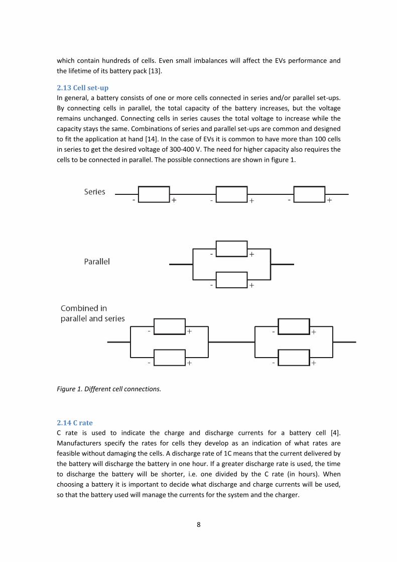
2.13 Cell set-up
In general, a battery consists of one or more cells connected in series and/or parallel set-ups.
By connecting cells in parallel, the total capacity of the battery increases, but the voltage
remains unchanged. Connecting cells in series causes the total voltage to increase while the
capacity stays the same. Combinations of series and parallel set-ups are common and designed
to fit the application at hand [14]. In the case of EVs it is common to have more than 100 cells
in series to get the desired voltage of 300-400 V. The need for higher capacity also requires the
cells to be connected in parallel. The possible connections are shown in figure 1.
Figure 1. Different cell connections.
2.14 C rate
C rate is used to indicate the charge and discharge currents for a battery cell [4].
Manufacturers specify the rates for cells they develop as an indication of what rates are
feasible without damaging the cells. A discharge rate of 1C means that the current delivered by
the battery will discharge the battery in one hour. If a greater discharge rate is used, the time
to discharge the battery will be shorter, i.e. one divided by the C rate (in hours). When
choosing a battery it is important to decide what discharge and charge currents will be used,
so that the battery used will manage the currents for the system and the charger.
9
Where h represents the time in hours for discharging at rate C. For example discharging a
battery with the capacity of 20 Ah, at 1C will discharge the battery with a constant current of
20 A. The total discharge time will then be 1 hour. If using a C-rate of 5C for the same battery,
the constant current will be 100 A with a discharge time of 1/5 hour, i.e. 12 minutes.
2.15 The LiFePO4 battery technology
Due to lithium’s high density of power and energy, it is a perfect candidate as an electrode
material [4][15]. Power density is a measure of energy throughput during discharge and energy
density is the amount of stored energy. Only Aluminum and Magnesium have better
properties, however lithium is preferred because of its low reactivity and better mechanical
characteristics [4]. Even so, lithium still reacts strongly with water, releasing hydrogen and
forming lithium hydroxide [16]. This reaction emits heat and may ignite the hydrogen and
cause the lithium to burn. It should, therefore, be handled with care and the electrolyte in
Lithium batteries should preferably be non-aqueous2 [4].
A Li-Ion battery cell contains other compounds than lithium, the actual amount of lithium is as
small as 3% [17]. When discharging a Li-Ion cell, the electrons in the electrode are released and
move through the external circuit providing energy, while the ions move through the
electrolyte. When charging a cell, the work is reversed, thus moving the ions back through the
electrolyte creating a swinging motion. The Li-Ion batteries are sometimes referred to as swing
batteries due to the swinging movement of the ions [1]. There are many different Li-Ion cells
with varying compound set-ups, for example, LiCoO2, LiMn2O4 and LiFePO4, and others.
2 The Lithium-Water battery is an exception
10
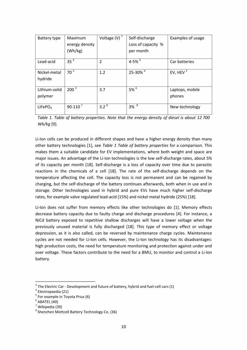
Battery type Maximum
energy density
(Wh/kg)
Voltage (V) 7 Self-discharge
Loss of capacity %
per month
Examples of usage
Lead-acid 35 3 2 4-5% 4 Car batteries
Nickel-metal
hydride
70 3 1.2 25-30% 4 EV, HEV 5
Lithium-solid
polymer
200 3 3.7 5% 6 Laptops, mobile
phones
LiFePO4 90-110 7 3.2 8 3% 8 New technology
Table 1. Table of battery properties. Note that the energy density of diesel is about 12 700
Wh/kg [9].
Li-Ion cells can be produced in different shapes and have a higher energy density than many
other battery technologies [1], see Table 1 Table of battery properties for a comparison. This
makes them a suitable candidate for EV implementations, where both weight and space are
major issues. An advantage of the Li-Ion technologies is the low self-discharge rates, about 5%
of its capacity per month [18]. Self-discharge is a loss of capacity over time due to parasitic
reactions in the chemicals of a cell [18]. The rate of the self-discharge depends on the
temperature affecting the cell. The capacity loss is not permanent and can be regained by
charging, but the self-discharge of the battery continues afterwards, both when in use and in
storage. Other technologies used in hybrid and pure EVs have much higher self-discharge
rates, for example valve regulated lead-acid (15%) and nickel metal hydride (25%) [18].
Li-Ion does not suffer from memory effects like other technologies do [1]. Memory effects
decrease battery capacity due to faulty charge and discharge procedures [4]. For instance, a
NiCd battery exposed to repetitive shallow discharges will have a lower voltage when the
previously unused material is fully discharged [18]. This type of memory effect or voltage
depression, as it is also called, can be reversed by maintenance charge cycles. Maintenance
cycles are not needed for Li-Ion cells. However, the Li-Ion technology has its disadvantages:
high production costs, the need for temperature monitoring and protection against under and
over voltage. These factors contribute to the need for a BMU, to monitor and control a Li-Ion
battery.
3 The Electric Car - Development and future of battery, hybrid and fuel-cell cars (1)
4 Electropaedia (21)
5 For example in Toyota Prius (6)
6 ABATEL (40)
7 Wikipedia (39)
8 Shenzhen Mottcell Battery Technology Co. (36)
11
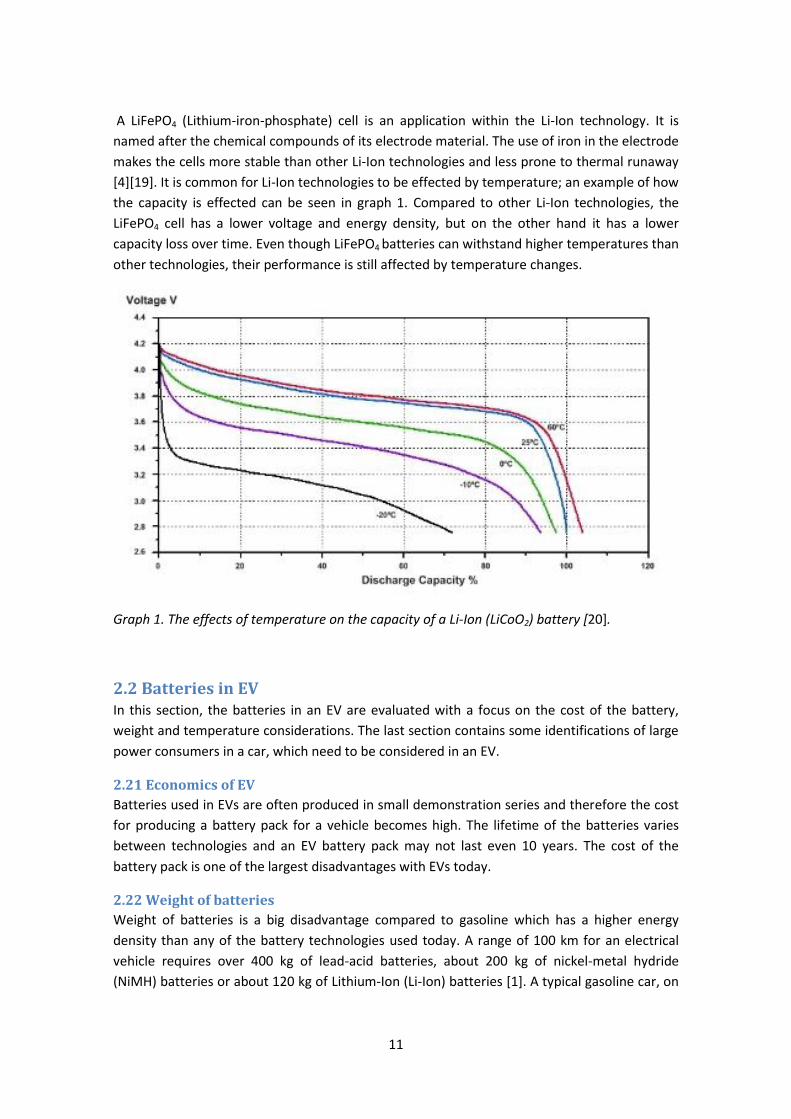
A LiFePO4 (Lithium-iron-phosphate) cell is an application within the Li-Ion technology. It is
named after the chemical compounds of its electrode material. The use of iron in the electrode
makes the cells more stable than other Li-Ion technologies and less prone to thermal runaway
[4][19]. It is common for Li-Ion technologies to be effected by temperature; an example of how
the capacity is effected can be seen in graph 1. Compared to other Li-Ion technologies, the
LiFePO4 cell has a lower voltage and energy density, but on the other hand it has a lower
capacity loss over time. Even though LiFePO4 batteries can withstand higher temperatures than
other technologies, their performance is still affected by temperature changes.
Graph 1. The effects of temperature on the capacity of a Li-Ion (LiCoO2) battery [20].
2.2 Batteries in EV In this section, the batteries in an EV are evaluated with a focus on the cost of the battery,
weight and temperature considerations. The last section contains some identifications of large
power consumers in a car, which need to be considered in an EV.
2.21 Economics of EV
Batteries used in EVs are often produced in small demonstration series and therefore the cost
for producing a battery pack for a vehicle becomes high. The lifetime of the batteries varies
between technologies and an EV battery pack may not last even 10 years. The cost of the
battery pack is one of the largest disadvantages with EVs today.
2.22 Weight of batteries
Weight of batteries is a big disadvantage compared to gasoline which has a higher energy
density than any of the battery technologies used today. A range of 100 km for an electrical
vehicle requires over 400 kg of lead-acid batteries, about 200 kg of nickel-metal hydride
(NiMH) batteries or about 120 kg of Lithium-Ion (Li-Ion) batteries [1]. A typical gasoline car, on
12
the other hand, may only need about 10 liters for the same range. Development is needed to
improve battery performance and weight to make EVs more comparable to conventional cars.
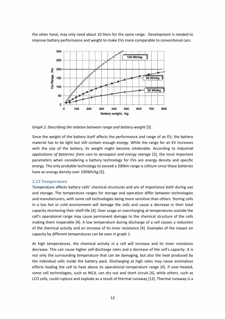
Graph 2. Describing the relation between range and battery weight [5]
Since the weight of the battery itself affects the performance and range of an EV, the battery
material has to be light but still contain enough energy. While the range for an EV increases
with the size of the battery, its weight might become intolerable. According to Industrial
applications of batteries: from cars to aerospace and energy storage [5], the most important
parameters when considering a battery technology for EVs are energy density and specific
energy. The only probable technology to exceed a 200km range is Lithium since these batteries
have an energy density over 100Wh/kg [5].
2.23 Temperature
Temperature affects battery cells’ chemical structures and are of importance both during use
and storage. The temperature ranges for storage and operation differ between technologies
and manufacturers, with some cell technologies being more sensitive than others. Storing cells
in a too hot or cold environment will damage the cells and cause a decrease in their total
capacity shortening their shelf-life [4]. Over usage or overcharging at temperatures outside the
cell’s operational range may cause permanent damage to the chemical structure of the cells
making them inoperable [4]. A low temperature during discharge of a cell causes a reduction
of the chemical activity and an increase of its inner resistance [4]. Examples of the impact on
capacity by different temperatures can be seen in graph 1.
At high temperatures, the chemical activity in a cell will increase and its inner resistance
decrease. This can cause higher self-discharge rates and a decrease of the cell’s capacity. It is
not only the surrounding temperature that can be damaging, but also the heat produced by
the individual cells inside the battery pack. Discharging at high rates may cause anomalous
effects leading the cell to heat above its operational temperature range [4]. If over-heated,
some cell technologies, such as NiCd, can dry out and short circuit [4], while others, such as
LCO cells, could rupture and explode as a result of thermal runaway [13]. Thermal runaway is a
13
chemical reaction caused in heated cells where the inner temperature causes more heat to be
exerted leading the cell to be exposed to hundreds of degrees Celsius. Some Li-Ion
technologies are especially prone to thermal runaway and caution should be taken during
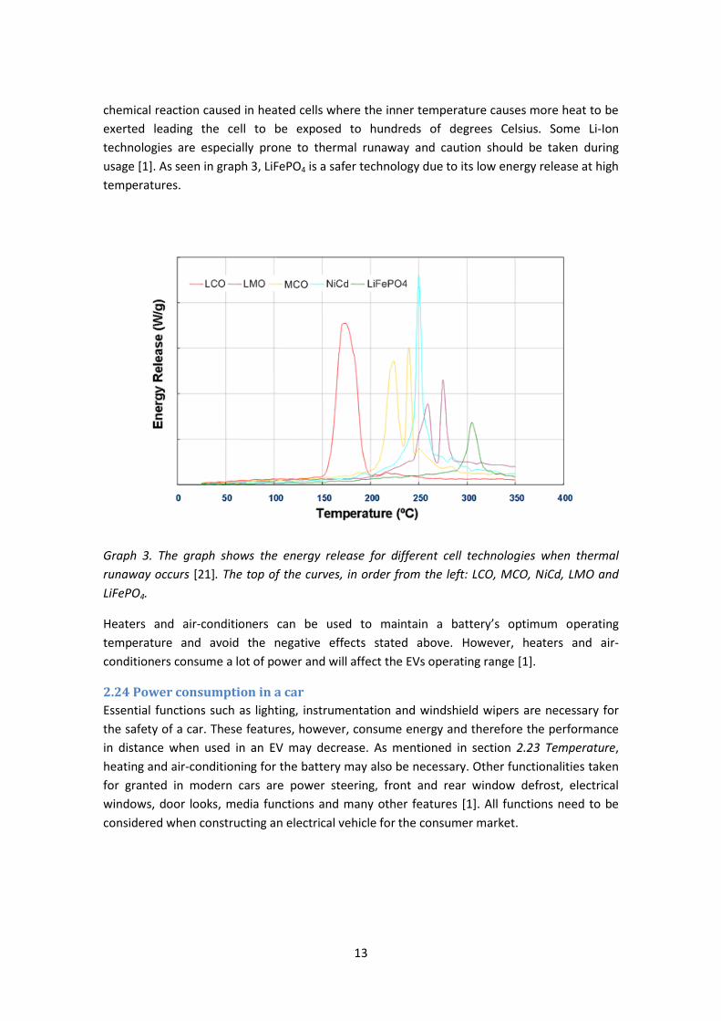
usage [1]. As seen in graph 3, LiFePO4 is a safer technology due to its low energy release at high
temperatures.
Graph 3. The graph shows the energy release for different cell technologies when thermal
runaway occurs [21]. The top of the curves, in order from the left: LCO, MCO, NiCd, LMO and
LiFePO4.
Heaters and air-conditioners can be used to maintain a battery’s optimum operating
temperature and avoid the negative effects stated above. However, heaters and air-
conditioners consume a lot of power and will affect the EVs operating range [1].
2.24 Power consumption in a car
Essential functions such as lighting, instrumentation and windshield wipers are necessary for
the safety of a car. These features, however, consume energy and therefore the performance
in distance when used in an EV may decrease. As mentioned in section 2.23 Temperature,
heating and air-conditioning for the battery may also be necessary. Other functionalities taken
for granted in modern cars are power steering, front and rear window defrost, electrical
windows, door looks, media functions and many other features [1]. All functions need to be
considered when constructing an electrical vehicle for the consumer market.
14
2.3 Charging This chapter discusses the charging of an EV and describes the different methods used today. It
also considers some of the difficulties faced when designing charging methods. Only the
charging technologies available to Li-Ion batteries have been accounted for in this section.
2.31 Charging technologies
Not all charging methods are suitable for Li-Ion cells due to their sensitivity to overheating and
under and over voltage. Compared to other technologies, the amount of parasitic processes is
low, thus minimizing the benefits of using more complex charging methods [4]. For example,
pulse charging would minimize the gas forming in a cell, but this is not a problem in the non
aqueous Li-Ion [4]. Overcharging is wasteful and damages both Li-Ion batteries and other
technologies [18]. According to Electric vehicle battery systems [18], overcharging is most likely
the biggest factor in reducing battery life [18].
Charging can be done at different rates, see 2.14 C rate above. When considering charging
methods for an EV, the most common rate being discussed is slow charge. In general, a typical
car is used during the day and has range of 40 km with an average energy consumption of 0.2
kWh per km [1]. With an optimal discharge rate of 80% this gives a total of 10 kWh needed for
the average commuter car per day and could easily be charged over night during an 8 hour
period [1]. This does, however, raise the question of fast charging EV batteries when needed.
At the moment, battery and EV manufacturers are working on enabling fast and flexible
charging for Li-Ion cells. Some have had successful results with fast charging, for example the
Think car company that has managed to charge from zero to 80 percent capacity in 15 minutes
[22]. Still, little is known of the long-term effects of such charging. Other research is focused on
changing the chemical structures in the Li-Ion cells to improve their charge performance
[23][24].
Some charging methods are described below.
Constant voltage
A constant voltage is applied until the battery voltage matches the charge voltage. This
method, combined with safety functions, can be used to charge Li-Ion batteries as long as the
current is limited. [18][21]
Constant current:
The voltage over the battery is varied during charging while the current maintains a fixed rate.
Charging is aborted when the battery voltage reaches its maximum value. This way of charging
makes it possible to keep track of the current input to the battery. On the other hand, charging
with a high current may cause overheating and electrolyte leakage in some batteries [18]. This
method can be used for Li-Ion batteries as long as the voltage is kept within range; if the
voltage reaches the over voltage limit safety functions should abort charging. This charging
method is mostly used for nickel metal hydride batteries. [18][21]

15
Pulse charge:
Charging the battery with a current pulse enables the charge rate to be more controlled.
Between pulses there is a short rest period. Voltage measurements can be done during pauses,
preferably at the end of the rest periods when the chemicals have stabilized a little. The
downside of this charging method is the duration; the pauses between pulses increase the
charge time compared to other charging methods. This method can be applied to Li-Ion, but is
mainly used for lead-acid batteries. [18][21]
Combined charge
Many EV charging systems combine constant voltage and constant current charging methods.
At first, constant voltage is applied to fill up the main part of the battery. Then a small constant
current is used for fine tuning, slowly charging the battery to its full capacity. Combining the
two reduces the risk of overcharging and damaging the battery. [18][21]
2.32 Effects of overcharging
Overcharging damages Li-Ion cells and can result in degraded cell capacity [13]. But early
charge termination due to safety functions against overloading may also have negative effects
on the available cell capacity. The safety functions abort charging as soon as one cell reaches
its over voltage threshold. The other cells will then be undercharged thus resulting in a
reduced available capacity [25]. These problems could be solved by intelligent cell balancing,
increasing both the available capacity and the battery’s lifetime.
2.33 Re-generative braking
Cars used in city and suburban traffic are subject to a large amount of repetitive start and stop
motions. Re-generative braking can be used to store energy otherwise lost when braking and
provide up to 15 percent extra range for a car [1][18]. The electric motor in an EV can be used
as a generator [1], as in the Toyota Prius hybrid EV [6]. To capture the momentum at
deceleration the generator is used to convert kinetic energy back to electric energy [18]. When
braking, the generator supplies the battery with a current which enables charging during drive
[1]. Both hybrid and pure EVs can benefit from re-generative braking.
Although it has energy saving benefits, re-generative braking exposes the battery to sudden
and high currents forcing it to fast charge [18]. This could be a problem with some battery
technologies, for example Li-Ion, where fast charging could damage the cells.
2.4 Safety of batteries in electric vehicles In the case of a car crash, it is important that the battery does not cause further damage.
Therefore, collision zones and guards for the battery need to be designed, to keep the battery
intact and in a safe place. Batteries and cables can be damaged and injure passengers with
acids, high temperatures and electric shocks [1]. One way to avoid injuries caused by the
batteries is to isolate the electric system and separate it from the vehicle chassis [1].
When short-circuits occur the energy stored in a battery is converted into heat within the
battery pack [4]. To prevent this, the terminals should be isolated and preferably have
16
different connectors to avoid mix-ups [4]. Additional protection against short-circuiting could
be fuses, circuit breakers and temperature sensors.
2.5 Environmental effects and recycling Lithium compositions, especially Lithium-Ion, in batteries are a fairly new technology.
Therefore, the long term usage and effects it might have on the environment are still
unknown. According to New metals and metalloids in society [26] there was still no recycling of
lithium in Sweden in 1999 and readings done at that time show minimal amounts of lithium in
the environment. On the other hand, Lithium-Ion is known to be a neurotoxin in humans and
long term exposure could lead to death [16].
For battery powered EVs to be environmentally acceptable, recycling methods are needed for
the batteries, especially when they may contain toxic material. Examples of batteries that
contain toxic materials are lead-acid batteries, nickel-cadmium batteries and Lithium-Ion
batteries [1]. At the time of recycling, it is important to gather all the components of the
battery, not only the most hazardous materials [17]. Even materials that are not dangerous
may have large effects at high concentrations if they spread or leak out of control [17]. For
example, in lead acid batteries, not only is lead a hazard, but also the electrolyte containing
sulfuric acid as well [17].
Even if the batteries are spent and thrown away, there may still be some remaining power.
This can be a risk if the batteries are not handled correctly during recycling [27]. The materials
can be toxic and need to be handled correctly to avoid injuries and environmental impacts
[27]. Since the beginning of lithium battery recycling in the USA, there have been great
improvements, from basic collection for disposal to more advanced material separation [28].
There are advantages and disadvantages with all recycling methods. One method described in
Recycling the Lithium battery [27] just melts the batteries with common metal smelting. This
method blends batteries into metals. This mixture of different metals can be refined and
separated by specialized companies [27]. Another method developed by Toxco Inc. is said to
recover 98 percent of the available lithium [28]. It is recovered as lithium carbonate which can
be converted into electrolyte and re-used in lithium batteries [28].
Recycling rates and recycling methods of batteries have been improved and developed over
time caused by new demands and new battery technologies. For instance, lead acid batteries
which have been used for a long time have a recycling rate that is better than 90 percent9 [17].
The recycling process is easier and requires less energy with nickel-cadmium and acid batteries
compared to zinc and lithium batteries [17] because cadmium and lead oxide are more easily
reduced back to pure metal.
9 In the United States
17
3. Theory of Battery Management Units A Battery Management Unit (BMU) monitors and controls a battery pack. The basic
functionalities in a BMU consist of safety functions, voltage and current measuring, State of
Charge (SOC) and temperature monitoring.
For Li-Ion battery packs, battery management is essential. Due to the nature of the Li-Ion
technology, the cells need to be controlled individually. For example, without a BMU, a Li-Ion
cell could easily be discharged under its voltage limit and be irreversibly damaged. As
mentioned in the introductory section 1.2 Battery Management Unit, individual control over
the cells also enables optimization of the stored energy, improving lifetime, safety and cost of
the battery pack. In an EV, a BMU is needed to keep track of the battery’s capacity status and
also to increase the safety and reliability of the vehicle.
3.1 State of Charge SOC To know how much capacity remains in a battery the SOC (State of Charge) is needed. SOC in
an EV is the same as a fuel gauge in a combustion engine; it is a measurement of the remaining
capacity of what the battery can deliver. SOC is usually stated as an estimation of the
remaining capacity, where 100% represents a fully charged battery. There are different ways
to measure the SOC, voltage and coulomb measuring being the most common.
3.11 Voltage measuring
The voltage of a battery is fairly easy to measure, but the quality of the estimated SOC based
on voltage measuring is hard to determine. For a Li-Ion battery where the charge and
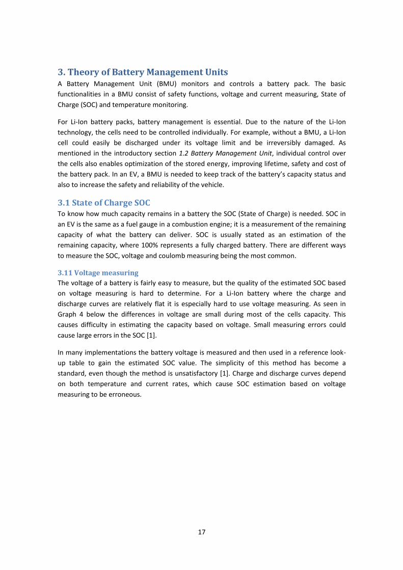
discharge curves are relatively flat it is especially hard to use voltage measuring. As seen in
Graph 4 below the differences in voltage are small during most of the cells capacity. This
causes difficulty in estimating the capacity based on voltage. Small measuring errors could
cause large errors in the SOC [1].
In many implementations the battery voltage is measured and then used in a reference look-
up table to gain the estimated SOC value. The simplicity of this method has become a
standard, even though the method is unsatisfactory [1]. Charge and discharge curves depend
on both temperature and current rates, which cause SOC estimation based on voltage
measuring to be erroneous.
18
Graph 4. Discharge curve for a 10Ah LiFePO4 cell. The voltage differences are small during most
of the cells capacity. See, for instance, the range 30-90% capacity where it is very difficult to
estimate capacity based on voltage since the difference is only a few mV.
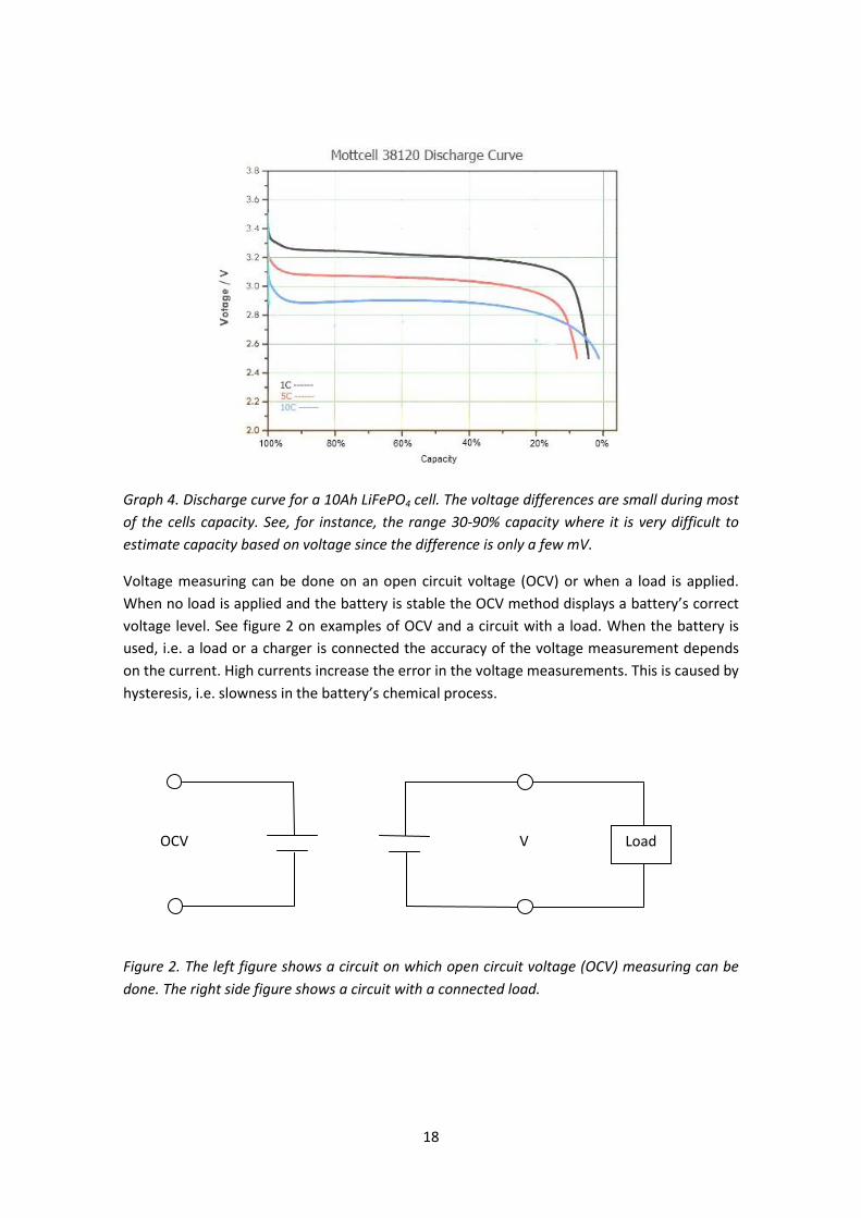
Voltage measuring can be done on an open circuit voltage (OCV) or when a load is applied.
When no load is applied and the battery is stable the OCV method displays a battery’s correct
voltage level. See figure 2 on examples of OCV and a circuit with a load. When the battery is
used, i.e. a load or a charger is connected the accuracy of the voltage measurement depends
on the current. High currents increase the error in the voltage measurements. This is caused by
hysteresis, i.e. slowness in the battery’s chemical process.
Figure 2. The left figure shows a circuit on which open circuit voltage (OCV) measuring can be
done. The right side figure shows a circuit with a connected load.
OCV Load V

19
3.12 Coulomb measurement
SOC can be estimated by keeping track of the in and out flowing currents of the battery. The
usual implementation of this method involves integration and is therefore a more expensive
solution. Integration requires more hardware and calculations to give an accurate estimation.
Another issue with Coulomb measurement (also called Coulomb counting) is how to manage
sudden current spikes. If the sampling frequency is too low currents spikes can be missed and
the coulomb counter will be inaccurate. This causes the SOC to drift away from its real value.
To minimize the errors due to drifting problems, the coulomb counter could be reset or re-
calibrated to its real value. When this is done the SOC will be accurate again.
3.13 Other possibilities to determine SOC
The difficulties concerning accuracy in SOC estimation have necessitated the development of
more techniques other than basic voltage and current measuring. Some methods could include
a battery cell model which can be used to correct the estimated SOC during runtime. Other
SOC estimations use more advanced methods such as neural networks [29], fuzzy logic and
readings of the chemical compositions and impedance of the cell [21]. Although there is
research within those areas, their actual implementation in real applications is unknown.
Other methods that currently have been used are filters, especially Kalman filters which
improve the estimation accuracy [30].
3.14 SOC dependability
A well defined SOC model should consider the changes in the battery’s capacity due to
temperature variations and the battery’s aging counted in charge cycles [10]. It is also
important to be aware that high temperatures damage the battery and cause it to age
prematurely. Batteries are considered aged and should not be used when the maximum
capacity is at 80% of its original capacity [1]. The error in the SOC estimation will increase if the
present capacity is used as the full capacity in SOC calculations. The decreasing capacity must
be considered when designing a SOC model.
The use of only voltage measuring cannot be seen as a sufficient method for SOC estimation.
Many implementations combine Coulomb and voltage measurement, some with other
techniques as well.
3.2 Cell balancing Even batteries produced from the same batch will never be identical [13]; there are always
small differences in self-discharge rate, capacity and impedance [4][13][14]. Therefore, the
cells in a battery pack may have different voltage levels after the battery has been fully
charged. To avoid damaging the cells due to imbalance in the battery pack, cell balancing is
used to reduce the difference in voltage between the cells. This gives cells longer lifetime and
more available capacity [14][25].
The differences between cells are especially important for Li-Ion batteries, since they are
sensitive to overcharging and deep discharge [11][13]. Imbalance in Lead-acid, NiMH and NiCd
batteries due to overcharging can be handled by a chemical short-circuit [25].
20
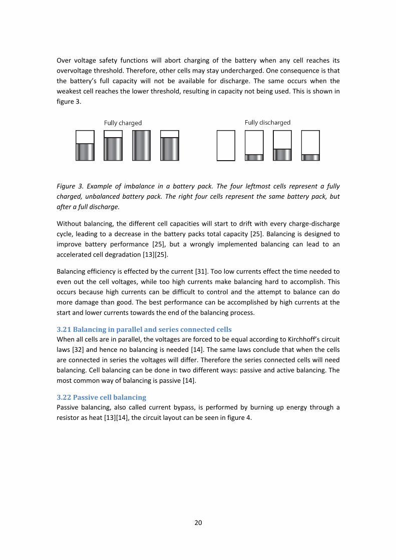
Over voltage safety functions will abort charging of the battery when any cell reaches its
overvoltage threshold. Therefore, other cells may stay undercharged. One consequence is that
the battery’s full capacity will not be available for discharge. The same occurs when the
weakest cell reaches the lower threshold, resulting in capacity not being used. This is shown in
figure 3.
Figure 3. Example of imbalance in a battery pack. The four leftmost cells represent a fully
charged, unbalanced battery pack. The right four cells represent the same battery pack, but
after a full discharge.
Without balancing, the different cell capacities will start to drift with every charge-discharge
cycle, leading to a decrease in the battery packs total capacity [25]. Balancing is designed to
improve battery performance [25], but a wrongly implemented balancing can lead to an
accelerated cell degradation [13][25].
Balancing efficiency is effected by the current [31]. Too low currents effect the time needed to
even out the cell voltages, while too high currents make balancing hard to accomplish. This
occurs because high currents can be difficult to control and the attempt to balance can do
more damage than good. The best performance can be accomplished by high currents at the
start and lower currents towards the end of the balancing process.
3.21 Balancing in parallel and series connected cells
When all cells are in parallel, the voltages are forced to be equal according to Kirchhoff’s circuit
laws [32] and hence no balancing is needed [14]. The same laws conclude that when the cells
are connected in series the voltages will differ. Therefore the series connected cells will need
balancing. Cell balancing can be done in two different ways: passive and active balancing. The
most common way of balancing is passive [14].
3.22 Passive cell balancing
Passive balancing, also called current bypass, is performed by burning up energy through a
resistor as heat [13][14], the circuit layout can be seen in figure 4.
21
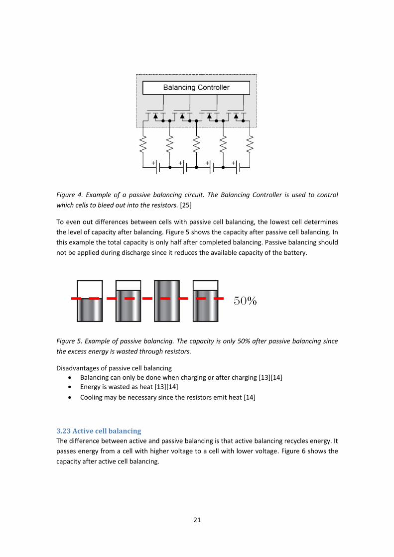
Figure 4. Example of a passive balancing circuit. The Balancing Controller is used to control
which cells to bleed out into the resistors. [25]
To even out differences between cells with passive cell balancing, the lowest cell determines
the level of capacity after balancing. Figure 5 shows the capacity after passive cell balancing. In
this example the total capacity is only half after completed balancing. Passive balancing should
not be applied during discharge since it reduces the available capacity of the battery.
Figure 5. Example of passive balancing. The capacity is only 50% after passive balancing since
the excess energy is wasted through resistors.
Disadvantages of passive cell balancing
Balancing can only be done when charging or after charging [13][14]
Energy is wasted as heat [13][14]
Cooling may be necessary since the resistors emit heat [14]
3.23 Active cell balancing
The difference between active and passive balancing is that active balancing recycles energy. It
passes energy from a cell with higher voltage to a cell with lower voltage. Figure 6 shows the
capacity after active cell balancing.
22
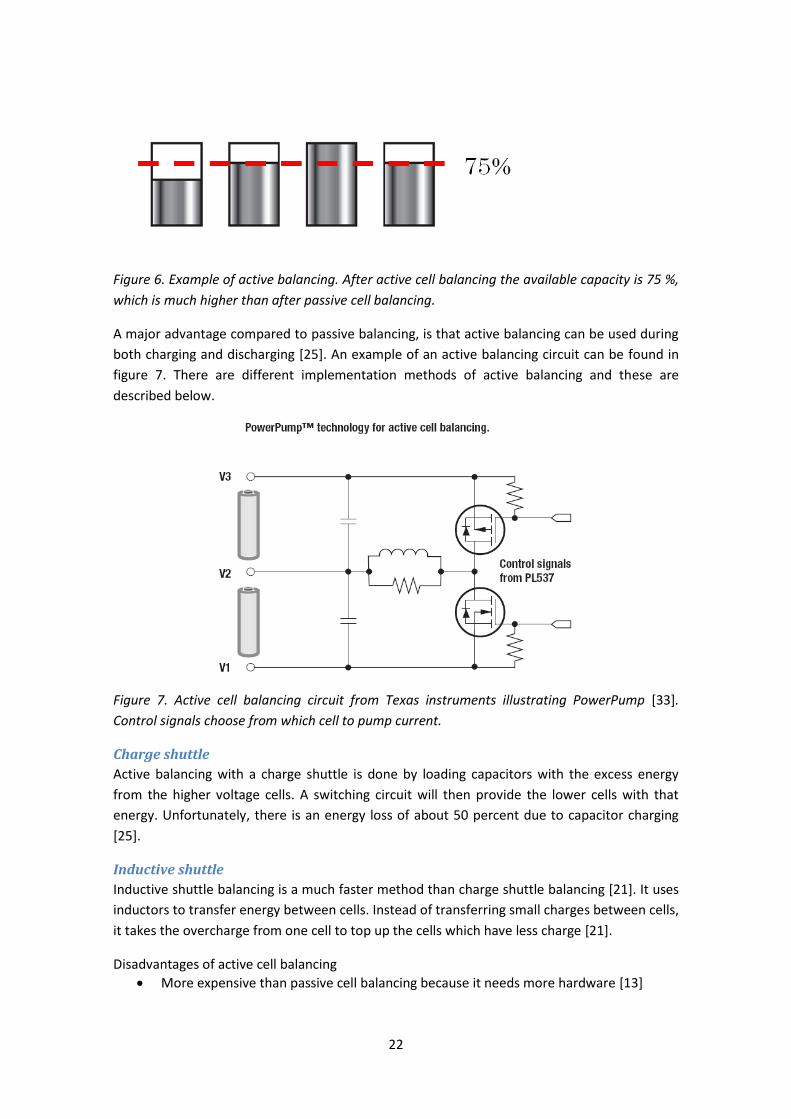
Figure 6. Example of active balancing. After active cell balancing the available capacity is 75 %,
which is much higher than after passive cell balancing.
A major advantage compared to passive balancing, is that active balancing can be used during
both charging and discharging [25]. An example of an active balancing circuit can be found in
figure 7. There are different implementation methods of active balancing and these are
described below.
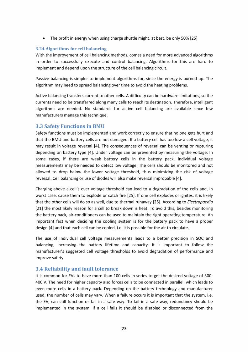
Figure 7. Active cell balancing circuit from Texas instruments illustrating PowerPump [33].
Control signals choose from which cell to pump current.
Charge shuttle
Active balancing with a charge shuttle is done by loading capacitors with the excess energy
from the higher voltage cells. A switching circuit will then provide the lower cells with that
energy. Unfortunately, there is an energy loss of about 50 percent due to capacitor charging
[25].
Inductive shuttle
Inductive shuttle balancing is a much faster method than charge shuttle balancing [21]. It uses
inductors to transfer energy between cells. Instead of transferring small charges between cells,
it takes the overcharge from one cell to top up the cells which have less charge [21].
Disadvantages of active cell balancing
More expensive than passive cell balancing because it needs more hardware [13]
23
The profit in energy when using charge shuttle might, at best, be only 50% [25]
3.24 Algorithms for cell balancing
With the improvement of cell balancing methods, comes a need for more advanced algorithms
in order to successfully execute and control balancing. Algorithms for this are hard to
implement and depend upon the structure of the cell balancing circuit.
Passive balancing is simpler to implement algorithms for, since the energy is burned up. The
algorithm may need to spread balancing over time to avoid the heating problems.
Active balancing transfers current to other cells. A difficulty can be hardware limitations, so the
currents need to be transferred along many cells to reach its destination. Therefore, intelligent
algorithms are needed. No standards for active cell balancing are available since few
manufacturers manage this technique.
3.3 Safety Functions in BMU Safety functions must be implemented and work correctly to ensure that no one gets hurt and
that the BMU and battery cells are not damaged. If a battery cell has too low a cell voltage, it
may result in voltage reversal [4]. The consequences of reversal can be venting or rupturing
depending on battery type [4]. Under voltage can be prevented by measuring the voltage. In
some cases, if there are weak battery cells in the battery pack, individual voltage
measurements may be needed to detect low voltage. The cells should be monitored and not
allowed to drop below the lower voltage threshold, thus minimizing the risk of voltage
reversal. Cell balancing or use of diodes will also make reversal improbable [4].
Charging above a cell’s over voltage threshold can lead to a degradation of the cells and, in
worst case, cause them to explode or catch fire [25]. If one cell explodes or ignites, it is likely
that the other cells will do so as well, due to thermal runaway [25]. According to Electropaedia
[21] the most likely reason for a cell to break down is heat. To avoid this, besides monitoring
the battery pack, air-conditioners can be used to maintain the right operating temperature. An
important fact when deciding the cooling system is for the battery pack to have a proper
design [4] and that each cell can be cooled, i.e. it is possible for the air to circulate.
The use of individual cell voltage measurements leads to a better precision in SOC and
balancing, increasing the battery lifetime and capacity. It is important to follow the
manufacturer’s suggested cell voltage thresholds to avoid degradation of performance and
improve safety.
3.4 Reliability and fault tolerance It is common for EVs to have more than 100 cells in series to get the desired voltage of 300-
400 V. The need for higher capacity also forces cells to be connected in parallel, which leads to
even more cells in a battery pack. Depending on the battery technology and manufacturer
used, the number of cells may vary. When a failure occurs it is important that the system, i.e.
the EV, can still function or fail in a safe way. To fail in a safe way, redundancy should be
implemented in the system. If a cell fails it should be disabled or disconnected from the
24
battery pack. In this chapter, some failures, risks, their effects and prevention methods are
presented.
3.41 Battery pack
The battery pack is protected by the BMU. Failure of cells cannot be completely avoided by
using a BMU, but, in the case of a failure, the BMU can detect and carry out precautions to
minimize the damage.
A short-circuit inside a battery cell, while rare [21], cannot be prevented by the BMU, fuses or
other external safety functions. The risk with internal short-circuit is total failure of the cell and
can be minimized by operating the battery pack within its recommended temperature range
[21].
In the case of high pressure10 caused by abuse or faulty sensors, the BMU cannot act. Instead,
a safety vent should be installed to prevent the battery from rupturing. In the case of an
accident, Electropaedia [21] states that EV batteries in general are a lower hazard than a full
tank of petrol.
In a Li-Ion battery pack that lacks a proper BMU, exchanging old or damaged cells will not
improve the battery. Instead, charging and discharging the battery with the new cell will cause
an accelerated degradation of the weaker cells. The exchanged cell will not increase the SOC
because the SOC is, in general, measured by the weakest cell [34]. Therefore, the whole
battery pack should be replaced when a cell fails [21].
The quality of the cells in the battery pack will also determine the failure rate. Higher quality
cells improve the whole battery pack. A battery pack contains a lot of series and parallel
connections and the failure rate of the whole battery pack is the sum of all failure rates of the
components (in this case battery cells and cables). Therefore, testing is needed to confirm the
quality and reliability of the cells and identify potential risks and hazards [21]. Different battery
technologies have their own specific cell construction, thus failing differently [21]. The
likelihood of failure in new cell technologies is higher since they often are produced manually
[21]. This increases the differences in cell capacity and inner resistance compared to cells that
have been mass-produced. Other failure possibilities are aging and abuse [21]. Often a single
failure does not directly lead to a complete breakdown of the cell, instead it usually degrades
the cells performance, i.e. reduced capacity, higher self-discharge etcetera [21]. According to
[21], the different failure modes when a complete breakdown occurs are: open circuit, short
circuit, explosion and fire. The failure mode cannot be predicted beforehand and depends on
the circumstances [21].
Improvements of lithium batteries have made them more reliable and safer to use [21]. Their
cell chemistry and more reliable manufacturing process are two of the improvements. The
BMU introduction has also improved the safety and enabled better operating conditions for
the battery cells.
10
Not all batteries.
25
Further improvements on the reliability of the battery pack can be performed by:
Using cells with higher capacity and C-rate than specified for the project to reduce the
risk of wear out
Substituting larger cells for smaller cells connected in parallel. Using parallel batteries
has the following benefits: in general they have lower failure rate, in case of failure it
has less stored energy that can damage the system and a failure of one cell will not
cause the entire battery pack to fail [21]
Implementing redundancy so that a single failure can be contained and the EV can
continue to operate. This can be done by dividing the battery pack into sections that
can be bypassed in case of failure [21]
3.42 BMU
As mentioned previously, the BMU monitors the battery pack and protects it from under-
/overvoltage and damaging temperatures. In the case of failure of the BMU caused, for
example, by sensor failures or loss of power, it is possible that the battery pack may be
overcharged or over discharged. This can be improved by redundancy in the BMU.
It is important that the BMU can detect insulation problems within the battery pack and shut
down the battery to avoid current leakage [18]. An inertia switch disconnects the battery pack
when it senses a fast deceleration as in a car accident [18].
3.43 Charging methods
An EV battery can be charged in two ways: conductive and inductive coupling [18]. The big
differences between the methods are that conductive coupling uses a physical cable while
inductive coupling uses inductive transmission caused by electromagnetic fields. An EV is going
to be used in all weather and the safety of charging is important. In the case of inductive
charging, the driver does not come in contact with any electrical interfaces. Conductive
coupling must be proper isolated and the user should not be able to short-circuit the EV or the
charging equipment [18]. It is also necessary to not connect or disconnect cables to the EV
during charging, in order to avoid electrical arcs [18]. To protect users, the charging equipment
should have a ground-fault circuit [18]. In inductive charging, this problem is minimized since
no cables are used.
26
4. Project implementation In this chapter, the implementation of the project is described and the design choices are
justified. First the choices regarding the assembly of the battery pack are discussed, such as
the connections and the specific cell for the implementation. This is then followed by an
overview of the system design, descriptions of the hardware and communication between
devices. Finally, the BMU implementation with its different parts is introduced.
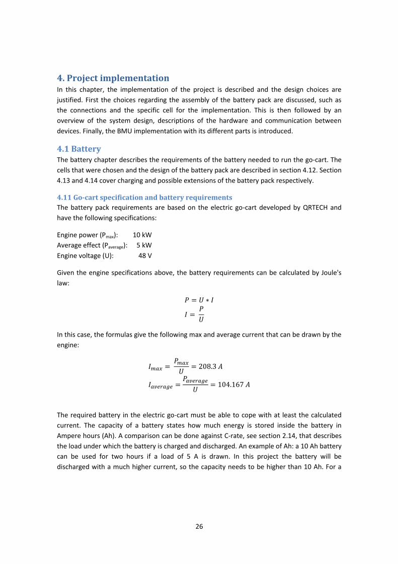
4.1 Battery The battery chapter describes the requirements of the battery needed to run the go-cart. The
cells that were chosen and the design of the battery pack are described in section 4.12. Section
4.13 and 4.14 cover charging and possible extensions of the battery pack respectively.
4.11 Go-cart specification and battery requirements
The battery pack requirements are based on the electric go-cart developed by QRTECH and
have the following specifications:
Engine power (Pmax): 10 kW
Average effect (Paverage): 5 kW
Engine voltage (U): 48 V
Given the engine specifications above, the battery requirements can be calculated by Joule's
law:
In this case, the formulas give the following max and average current that can be drawn by the
engine:
The required battery in the electric go-cart must be able to cope with at least the calculated
current. The capacity of a battery states how much energy is stored inside the battery in
Ampere hours (Ah). A comparison can be done against C-rate, see section 2.14, that describes
the load under which the battery is charged and discharged. An example of Ah: a 10 Ah battery
can be used for two hours if a load of 5 A is drawn. In this project the battery will be
discharged with a much higher current, so the capacity needs to be higher than 10 Ah. For a
27
drive time between 5-8 minutes11, the battery capacity must be 20 Ah. Calculation of time is
shown below:
The shortest driving time is when the highest current Imax is drawn and the driving time will
increase when the current decreases. The calculated Iaverage gives us an average of the time for
driving, see the calculations below:
Note that the max current (Imax) will only be drawn for a short period, i.e. for a couple of
seconds. The average is a more likely estimation. Another important aspect in selecting cells is
to keep down the weight and volume, since the battery pack will be placed on a go-cart.
Figure 8. The electric go-cart at QRTECH [35]
4.12 Cell specification and design of battery pack
At the time of writing, LiFePO4 is considered by many to be the near future battery technology
for EVs [19][1]. As stated previously, LiFePO4 cells provide enough capacity and power to be
applicable in modern EVs. It also has lower weight and is safer than other battery technologies.
11
Specification by QRTECH (35)
28
After the cell requirement for the project was determined, the right batteries needed to be
located through a cell manufacturer. Appendix C contains a list of all LiFePO4 cell suppliers that
were considered. ABATEL, a consultancy firm within battery solutions, provided the project
with cells from Shenzhen Mottcell Battery Technology.
Cell specification
The cells used in the project will be parallel connected to achieve the desired capacity of 20
Ah. The parallel cell pack has following specifications:
Voltage: 3.2 V
Capacity: 20 Ah
Constant current: ≤200 A
Max current: ≤300 A
Cycle life: 2000 cycles12
Min / max voltage: 2.0 V / 3.65 V
Internal resistance: <10 mΩ
Self discharge: 3% per month13
Weight: 700 g
A more detailed description of the cells can be found in Appendix B.
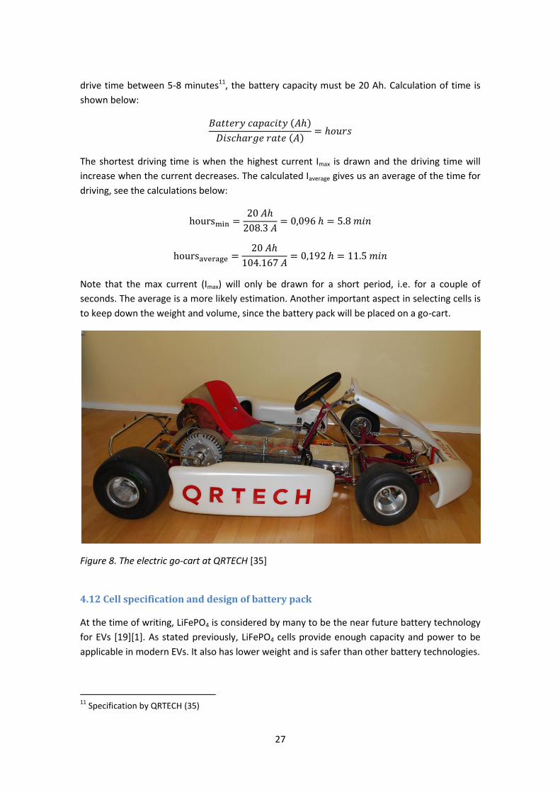
The decision to have two cells in parallel was made to reduce the exhaustion which can occur
with a single cell, as described in section 3.41 Battery pack. Other cells that were considered
for the implementation had 20 Ah per cell, but the discharge current rates were lower.
Therefore, they could not be used in the go-cart since it needs high currents rates. To achieve
the required voltage of 48 V for the engine, a series connection was also needed in the battery
pack. Since each cell has a nominal voltage of 3.2 the battery pack needed 15 series connected
cells. The total weight for the battery pack was 15*0.7 = 10.5 kg, which is quite low.
12
Higher than 70% of its capacity, see Appendix C 13
Temperature 25±5°C
29
Figure 9. Picture of the LiFePO4 battery pack. The cells are shown connected in parallel.
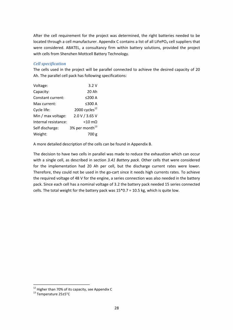
Discharge curves
Discharge curves are constructed by discharging the battery pack at different C-rates. These
curves were needed to design and test a SOC. Graph 5 below shows the discharge curves for
the LiFePO4cell used in this project. The top curve represents discharging a cell at 1 C, which in
this case means discharging for 1 hour at a constant current of 20 A. The middle curve
represents discharging at 5 C, i.e. five times faster discharging than the top curve. Thus, the
middle curve discharges with a constant current of 200A which takes about 12 minutes.
Graph 5. The discharge curve for the LiFePO4 battery cells used in the project [36].
30
4.13 Charging method for the battery pack
The battery pack is charged with a power supply using a constant voltage of 48 V and a
constant current of max 10 A. Safety functions will abort charging if any cell reaches the over
voltage limit of 3.6 V. The nominal voltage of a LiFePO4 cell is about 3.2 V, but it can sustain
higher voltages. The cells used in this project have a top limit of 3.6 V. As stated in section 3.3
Safety Functions in BMU, charging above its limit will damage the cell. To charge the battery at
10 A to 100% of its capacity will take about 2 hours14.
After a charge, the battery is left to rest. A period of 30 minutes is enough for the cells to
stabilize and result in more accurate voltage readings [37]. Balancing takes place after the rest
period. Now the SOC can be investigated to see if a new round of charging should be
performed. High imbalance can cause the capacity to be much lower than feasible, see chapter
3.2.
4.14 Extending the battery pack
To boost the capacity and range of the go-cart, more cells can be connected in parallel.
Although it would not require major changes to the implemented BMU, a higher capacity
would increase the cost, space and weight of the battery pack. These three factors limit the
range of the go-cart, but the main idea with this master thesis was to construct a battery pack
for testing, not to enable the same speed or range as in a real car.
Extensions to a battery pack to increase its voltage can be managed by extending the BMU and
adding more balancing boards. Only minor changes to the BMU would be needed since the
code is generic.
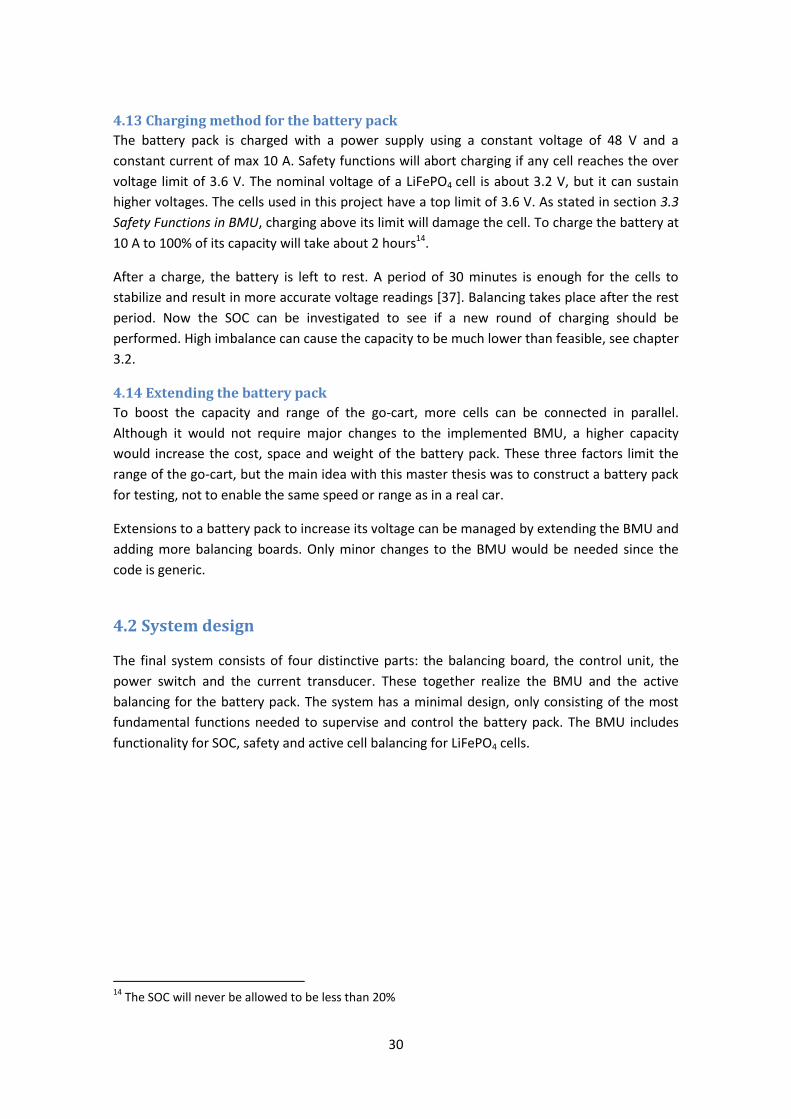
4.2 System design
The final system consists of four distinctive parts: the balancing board, the control unit, the
power switch and the current transducer. These together realize the BMU and the active
balancing for the battery pack. The system has a minimal design, only consisting of the most
fundamental functions needed to supervise and control the battery pack. The BMU includes
functionality for SOC, safety and active cell balancing for LiFePO4 cells.
14
The SOC will never be allowed to be less than 20%
31
Figure 10. Overview of the implemented system.
As seen in figure 10 the system consists of two major blocks, the control unit and the balancing
board. The control unit contains a microcontroller on a BMU board and works as the host of
the system, with the balancing board as slave. The balancing board has 3 devices, which
control 5 cells each. The cells are connected as stated in the previous section 4.1 Battery. The
relay is the power switch for the system; it is used to cut off the power to the engine or
charger. It is controlled by safety functions inside the BMU. A current transducer is needed to
measure the current through the battery, for more details on this see the section below about
the Current Transducer. The communications interface and protocol between the control unit
and the balancing board are described in section 4.22 Communication. In debug mode, the
communication to the PC is used for printing messages. The communication to the control unit
from the PC is handled by a hardware programmer from Atmel and is not described in this
thesis.
4.21 Hardware design
The main reason for starting this project at QRTECH was to try out new technology, ideas and
hardware. Since QRTECH has previously worked on similar, but larger BMU projects, they had
experience in this field and could suggest hardware fitting the project. Through QRTECHs
contact with Texas Instruments, the project was supplied with a brand new prototype unit,
bq76PL537, with active balancing and internal voltage measuring. The prototype was
examined and tested to see if it could be integrated in the project. Since the results were
adequate and active balancing is highly interesting, the rest of the project was designed
around the prototype. Previous EV projects at QRTECH had lead to the development of a
circuit board for a BMU. This circuit board was also to be tested in the project and became the
base for the projects control unit. As stated in the introduction, one of the main goals was to
implement a small, but yet efficient BMU. Therefore, the choice of control unit fell upon the
32
Atmel Mega 168. The microcontroller and other hardware used in this project are described in
the following sections.
Control unit
An 8-bit microcontroller from Atmel was used as the control unit. The Atmel Mega 168
(ATmega168) was chosen by QRTECH for the project first and foremost due to its compatibility
with their previously designed BMU board. More general benefits of the ATmega168 are low
cost and low power consumption [38]. ATmega168 also has an internal Analog to Digital
Converter (ADC) which was needed for this project. The ADC was used for converting the
measurements from current flows; for further details see Current transducer below. The main
drawback of the ATmega168 is the limited memory space which greatly affected the layout of
the project. The available memory had massive impact on the system design in general, forcing
the BMU to be slimmed down to its core functions. While the limited memory affected every
aspect of the design, the performance of the ATmega168 had the largest impact on the SOC
design. Floating point operations and large integration calculations had to be excluded. These,
in turn, effect the accuracy of the SOC estimation.
In the final implementation, the ATmega168 included the BMU and initialization of the
balancing board. The implemented BMU had control over charging procedures, SOC, balancing
algorithm and safety functions. For debugging purposes, a UART communications interface
was used to output messages on a PC. The software was programmed in C with AVR Studio
and debugged in Eclipse.
Current transducer
A HASS 100-S current transducer was used to measure the current flow in and out of the
battery. The current transducer surrounds the power cable and senses the magnetic field
caused by the current. A current in the range +/- 300A can be measured and the HASS 100-S
outputs a voltage between 0-5V. The zero reference voltage is 2,5 V. The voltage output can be
converted through the Atmega168 internal ADC to a digital representation. The digital value is
then converted to a value representing the current. Those currents can then be used for
current counting within the BMU.
BMU board
The BMU circuit board was developed by QRTECH for EV implementations. The board suited
the project and was chosen as the base of the control unit. It consists of a printed circuit board
and component schematics. Before it could be used, the components had to be ordered,
assembled and soldered by hand. The components used were diodes and resistors for
protection, LEDs for indication, USB interface for debugging purposes, a power converter to
supply the board with 5 V and filters to reduce noise. After each major group of components
had been soldered, the voltages were measured to check if they were properly mounted. The
final BMU board can be seen in figure 11.
It was not possible to test the BMU board fully until the ATmega168 had been soldered and
programmed. Some difficulties with setting-up the board were caused by differences in the
schematics and the printed circuit board. For instance, some of the connections on the board
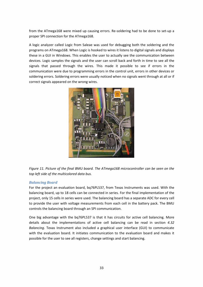
33
from the ATmega168 were mixed up causing errors. Re-soldering had to be done to set-up a
proper SPI connection for the ATmega168.
A logic analyzer called Logic from Saleae was used for debugging both the soldering and the
programs on ATmega168. When Logic is hooked to wires it listens to digital signals and displays
these in a GUI in Windows. This enables the user to actually see the communication between
devices. Logic samples the signals and the user can scroll back and forth in time to see all the
signals that passed through the wires. This made it possible to see if errors in the
communication were due to programming errors in the control unit, errors in other devices or
soldering errors. Soldering errors were usually noticed when no signals went through at all or if
correct signals appeared on the wrong wires.
Figure 11. Picture of the final BMU board. The ATmega168 microcontroller can be seen on the
top left side of the multicolored data bus.
Balancing Board
For the project an evaluation board, bq76PL537, from Texas Instruments was used. With the
balancing board, up to 18 cells can be connected in series. For the final implementation of the
project, only 15 cells in series were used. The balancing board has a separate ADC for every cell
to provide the user with voltage measurements from each cell in the battery pack. The BMU
controls the balancing board through an SPI communication.
One big advantage with the bq76PL537 is that it has circuits for active cell balancing. More
details about the implementations of active cell balancing can be read in section 4.32
Balancing. Texas Instrument also included a graphical user interface (GUI) to communicate
with the evaluation board. It initiates communication to the evaluation board and makes it
possible for the user to see all registers, change settings and start balancing.
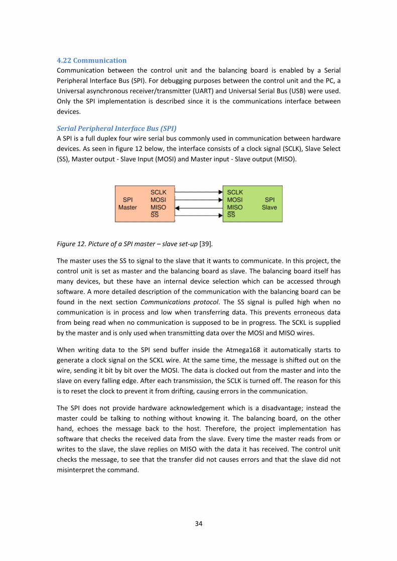
34
4.22 Communication
Communication between the control unit and the balancing board is enabled by a Serial
Peripheral Interface Bus (SPI). For debugging purposes between the control unit and the PC, a
Universal asynchronous receiver/transmitter (UART) and Universal Serial Bus (USB) were used.
Only the SPI implementation is described since it is the communications interface between
devices.
Serial Peripheral Interface Bus (SPI)
A SPI is a full duplex four wire serial bus commonly used in communication between hardware
devices. As seen in figure 12 below, the interface consists of a clock signal (SCLK), Slave Select
(SS), Master output - Slave Input (MOSI) and Master input - Slave output (MISO).
Figure 12. Picture of a SPI master – slave set-up [39].
The master uses the SS to signal to the slave that it wants to communicate. In this project, the
control unit is set as master and the balancing board as slave. The balancing board itself has
many devices, but these have an internal device selection which can be accessed through
software. A more detailed description of the communication with the balancing board can be
found in the next section Communications protocol. The SS signal is pulled high when no
communication is in process and low when transferring data. This prevents erroneous data
from being read when no communication is supposed to be in progress. The SCKL is supplied
by the master and is only used when transmitting data over the MOSI and MISO wires.
When writing data to the SPI send buffer inside the Atmega168 it automatically starts to
generate a clock signal on the SCKL wire. At the same time, the message is shifted out on the
wire, sending it bit by bit over the MOSI. The data is clocked out from the master and into the
slave on every falling edge. After each transmission, the SCLK is turned off. The reason for this
is to reset the clock to prevent it from drifting, causing errors in the communication.
The SPI does not provide hardware acknowledgement which is a disadvantage; instead the
master could be talking to nothing without knowing it. The balancing board, on the other
hand, echoes the message back to the host. Therefore, the project implementation has
software that checks the received data from the slave. Every time the master reads from or
writes to the slave, the slave replies on MISO with the data it has received. The control unit
checks the message, to see that the transfer did not causes errors and that the slave did not
misinterpret the command.
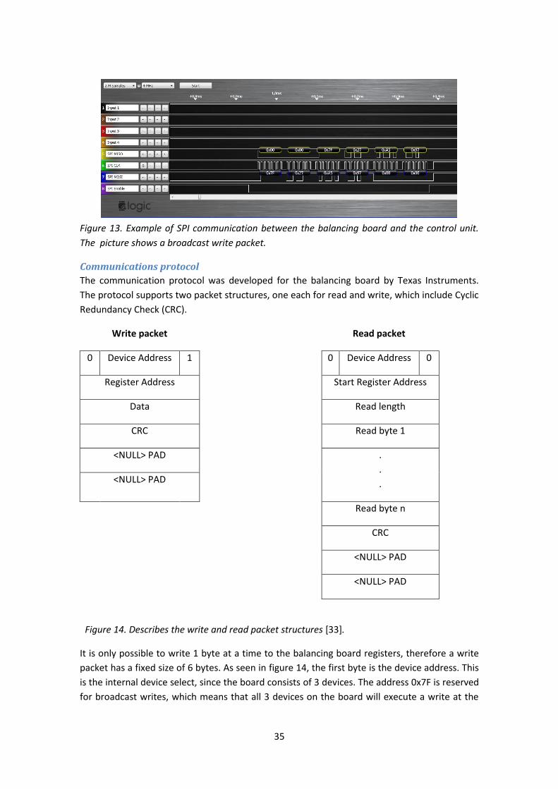
35
Figure 13. Example of SPI communication between the balancing board and the control unit.
The picture shows a broadcast write packet.
Communications protocol
The communication protocol was developed for the balancing board by Texas Instruments.
The protocol supports two packet structures, one each for read and write, which include Cyclic
Redundancy Check (CRC).
Write packet Read packet
0 Device Address 1 0 Device Address 0
Register Address Start Register Address
Data Read length
CRC Read byte 1
<NULL> PAD .
.
. <NULL> PAD
Read byte n
CRC
<NULL> PAD
<NULL> PAD
Figure 14. Describes the write and read packet structures [33].
It is only possible to write 1 byte at a time to the balancing board registers, therefore a write
packet has a fixed size of 6 bytes. As seen in figure 14, the first byte is the device address. This
is the internal device select, since the board consists of 3 devices. The address 0x7F is reserved
for broadcast writes, which means that all 3 devices on the board will execute a write at the
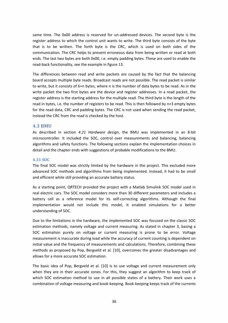
36
same time. The 0x00 address is reserved for un-addressed devices. The second byte is the
register address to which the control unit wants to write. The third byte consists of the byte
that is to be written. The forth byte is the CRC, which is used on both sides of the
communication. The CRC helps to prevent erroneous data from being written or read at both
ends. The last two bytes are both 0x00, i.e. empty padding bytes. These are used to enable the
read-back functionality, see the example in figure 13.
The differences between read and write packets are caused by the fact that the balancing
board accepts multiple byte reads. Broadcast reads are not possible. The read packet is similar
to write, but it consists of 6+n bytes, where n is the number of data bytes to be read. As in the
write packet the two first bytes are the device and register addresses. In a read packet, the
register address is the starting address for the multiple read. The third byte is the length of the
read in bytes, i.e. the number of registers to be read. This is then followed by n+3 empty bytes
for the read data, CRC and padding bytes. The CRC is not used when sending the read packet,
instead the CRC from the read is checked by the host.
4.3 BMU As described in section 4.21 Hardware design, the BMU was implemented in an 8-bit
microcontroller. It included the SOC, control over measurements and balancing, balancing
algorithms and safety functions. The following sections explain the implementation choices in
detail and the chapter ends with suggestions of probable modifications to the BMU.
4.31 SOC
The final SOC model was strictly limited by the hardware in the project. This excluded more
advanced SOC methods and algorithms from being implemented. Instead, it had to be small
and efficient while still providing an accurate battery status.
As a starting point, QRTECH provided the project with a Matlab Simulink SOC model used in
real electric cars. The SOC model considers more than 30 different parameters and includes a
battery cell as a reference model for its self-correcting algorithms. Although the final
implementation would not include this model, it enabled simulations for a better
understanding of SOC.
Due to the limitations in the hardware, the implemented SOC was focused on the classic SOC
estimation methods, namely voltage and current measuring. As stated in chapter 3, basing a
SOC estimation purely on voltage or current measuring is prone to be error. Voltage
measurement is inaccurate during load while the accuracy of current counting is dependent on
initial value and the frequency of measurements and calculations. Therefore, combining these
methods as proposed by Pop, Bergveld et al. [10], overcomes the greater disadvantages and
allows for a more accurate SOC estimation.
The basic idea of Pop, Bergveld et al. [10] is to use voltage and current measurement only
when they are in their accurate zones. For this, they suggest an algorithm to keep track of
which SOC estimation method to use in all possible states of a battery. Their work uses a
combination of voltage measuring and book-keeping. Book-keeping keeps track of the currents
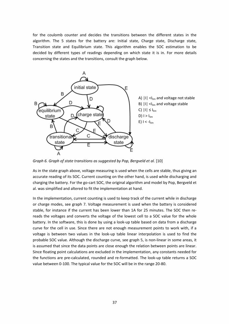
37
for the coulomb counter and decides the transitions between the different states in the
algorithm. The 5 states for the battery are: Initial state, Charge state, Discharge state,
Transition state and Equilibrium state. This algorithm enables the SOC estimation to be
decided by different types of readings depending on which state it is in. For more details
concerning the states and the transitions, consult the graph below.
A) |I| <Ilim and voltage not stable
B) |I| <Ilim and voltage stable
C) |I| ≤ Ilim
D) I > Ilim
E) I < -Ilim
Graph 6. Graph of state transitions as suggested by Pop, Bergveld et al. [10]
As in the state graph above, voltage measuring is used when the cells are stable, thus giving an
accurate reading of its SOC. Current counting on the other hand, is used while discharging and
charging the battery. For the go-cart SOC, the original algorithm and model by Pop, Bergveld et
al. was simplified and altered to fit the implementation at hand.
In the implementation, current counting is used to keep track of the current while in discharge
or charge modes, see graph 7. Voltage measurement is used when the battery is considered
stable, for instance if the current has been lower than 1A for 25 minutes. The SOC then re-
reads the voltages and converts the voltage of the lowest cell to a SOC value for the whole
battery. In the software, this is done by using a look-up table based on data from a discharge
curve for the cell in use. Since there are not enough measurement points to work with, if a
voltage is between two values in the look-up table linear interpolation is used to find the
probable SOC value. Although the discharge curve, see graph 5, is non-linear in some areas, it
is assumed that since the data points are close enough the relation between points are linear.
Since floating point calculations are excluded in the implementation, any constants needed for
the functions are pre-calculated, rounded and re-formatted. The look-up table returns a SOC
value between 0-100. The typical value for the SOC will be in the range 20-80.
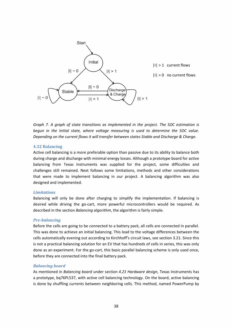
38
|I| > 1 current flows
|I| ≈ 0 no current flows
Graph 7. A graph of state transitions as implemented in the project. The SOC estimation is
begun in the Initial state, where voltage measuring is used to determine the SOC value.
Depending on the current flows it will transfer between states Stable and Discharge & Charge.
4.32 Balancing
Active cell balancing is a more preferable option than passive due to its ability to balance both
during charge and discharge with minimal energy losses. Although a prototype board for active
balancing from Texas Instruments was supplied for the project, some difficulties and
challenges still remained. Next follows some limitations, methods and other considerations
that were made to implement balancing in our project. A balancing algorithm was also
designed and implemented.
Limitations
Balancing will only be done after charging to simplify the implementation. If balancing is
desired while driving the go-cart, more powerful microcontrollers would be required. As
described in the section Balancing algorithm, the algorithm is fairly simple.
Pre-balancing
Before the cells are going to be connected to a battery pack, all cells are connected in parallel.
This was done to achieve an initial balancing. This lead to the voltage differences between the
cells automatically evening out according to Kirchhoff’s circuit laws, see section 3.21. Since this
is not a practical balancing solution for an EV that has hundreds of cells in series, this was only
done as an experiment. For the go-cart, this basic parallel balancing scheme is only used once,
before they are connected into the final battery pack.
Balancing board
As mentioned in Balancing board under section 4.21 Hardware design, Texas Instruments has
a prototype, bq76PL537, with active cell balancing technology. On the board, active balancing
is done by shuffling currents between neighboring cells. This method, named PowerPump by
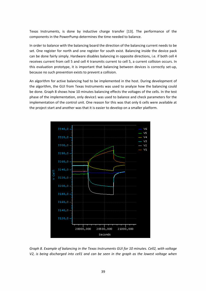
39
Texas Instruments, is done by inductive charge transfer [13]. The performance of the
components in the PowerPump determines the time needed to balance.
In order to balance with the balancing board the direction of the balancing current needs to be
set. One register for north and one register for south exist. Balancing inside the device pack
can be done fairly simply. Hardware disables balancing in opposite directions, i.e. if both cell 4
receives current from cell 5 and cell 4 transmits current to cell 5, a current collision occurs. In
this evaluation prototype, it is important that balancing between devices is correctly set-up,
because no such prevention exists to prevent a collision.
An algorithm for active balancing had to be implemented in the host. During development of
the algorithm, the GUI from Texas Instruments was used to analyze how the balancing could
be done. Graph 8 shows how 10 minutes balancing effects the voltages of the cells. In the test
phase of the implementation, only device1 was used to balance and check parameters for the
implementation of the control unit. One reason for this was that only 6 cells were available at
the project start and another was that it is easier to develop on a smaller platform.
Graph 8. Example of balancing in the Texas Instruments GUI for 10 minutes. Cell2, with voltage
V2, is being discharged into cell1 and can be seen in the graph as the lowest voltage when

40
discharging. Cell1, with voltage V1, is the second highest cell being charged. After charging,
about 30 minutes is needed for the cells to stabilize. Therefore, the voltages just after
balancing, as shown at the end of the graph, are not yet accurate.
Balancing algorithm
The algorithm should balance both between devices and in the device pack. To simplify the
implementation of the balancing, two different algorithms were designed, one for balancing
between devices and one for balancing in the device pack.
Balancing between devices
First the device with highest voltage balances its current to the device with lowest voltage. The
direction in north and south registers need to be set. In max and min devices the directions are
decided before the balancing of the device, namely by choosing to forward current to the
lowest cell in the device and draw current from the cell with highest voltage.
After a balancing period, directions are recalculated, i.e. to choose new max and min devices.
Also, new min and max cells are located within those devices. Then balancing starts again and
is finished when the differences between devices are smaller than the decided limit. A rest
period of 30 minutes must now occur to allow the voltages to stabilize. One difficulty with the
device to device balancing algorithm is to avoid collisions between devices, since no safety
mechanisms are implemented in the hardware.
Balancing in device pack
After the balancing between devices is complete, balancing in the device pack will be
performed. Two possible solutions exist, all cells balance to the lowest or balance to a local
minimum. After modeling cell balancing in Excel, it was decided to choose the latter option.
The chosen algorithm to be implemented has simpler calculations and seems to be more
effective when small cell differences exist. The main idea is to avoid drift caused by complex
and untested algorithms.
4.33 Safety
In order to avoid under and over voltages, safety functions need to be implemented. During all
the states of the go-cart (charging, balancing, driving), safety checks are continuously executed
to determine under and over voltages. All states are aborted by sending signals to a relay that
disables the battery connection to the electric co-cart. Fuses are also used to limit the current
drawn.
4.34 Extending the BMU
During the project many alterations to the BMU were discussed. Due to the limitations of this
thesis, many of them could not be implemented during the project. Instead, some of the
suggestions are listed in this section with a short description of the main idea and the probable
benefits of the changes.
Improvements of SOC
The implemented SOC accuracy will decrease over time and it does not contain any advanced
self-correcting algorithms. Therefore, it will keep drifting away from its real value when
41
discharging due to the drift in the current counter. Many papers that were studied made use
of filters such as Kalman filters. By using filters, it should be possible to better the accuracy of
the SOC. A microcontroller with higher capacity would be needed for such an improvement.
It would be interesting to use parallel processors for a BMU project. The accuracy of the
current counting is dependent on the frequency of its readings. If one micro controller would
be programmed to only do current counting, the frequency would be higher than on the
ATmega168. At the moment, there are too many other functions that need to run in sequence
between current readings. This type of parallelism could also be implemented in a single
ATmega168 if re-writing the software to be driven by interrupts.
Voltage measurements for SOC estimation could be used more often if there was a correcting
algorithm for the voltage levels. The algorithm could calculate the difference between the real
and the measured voltage. Then, a more accurate SOC could be accomplished. This would
require a larger and faster microcontroller to handle more detailed information about the
cells.
Improvements of balancing
Balancing algorithms can be more optimized to perform better. Also the balancing algorithm
can be executed several times with rest period between, to minimize drift caused by
hysteresis. Balancing can also be performed several times, before, during and after charging.
4.4 Tools A varied set of software tools were used during the project. Only the major ones are listed
below.
AVR Studio
AVR Studio is a free Integrated Development Environment (IDE) for developing 8-bit AVR
applications in Windows environments [38]. It has support for the ATmega168 which was used
in the project. AVR Studio includes an assembler, a compiler, a simulator and a debugging
interface.
Eclipse
Eclipse is a free IDE for various programming languages. It can be extended with different plug-
ins. In this project Eclipse Galileo, C/C++ Development Tools and an external C compiler were
used to program and debug software for the BMU.
Matlab, Simulink and Real Time Workshop
A broad description of Matlab is that it is a program used for numerical computing. It can be
used for instance manipulating matrixes, plotting graphs and calculating equations. Simulink,
an add-on for Matlab, is a graphical block diagramming tool that was used to simulate a BMU
model. In Simulink, it is possible to simulate certain scenarios which can occur in a BMU. For
instance, it was possible to see if safety functions were working properly and what the SOC
value was during a simulated run. Simulink combined with the add-on Real Time Workshop
made it possible to generate C code from models. Since Real Time Workshop has support for

42
the ATmega168 it was used for generating code. The generated code was examined in the
project, but never used in the final implementation.
Microsoft Office Excel
Excel is a spreadsheet application. It can handle both basic calculations and programs. A
simulation of a balancing algorithm in Excel was provided by Texas Instruments. Therefore, the
rest of the simulations for the balancing algorithms were also implemented in Excel. The
program was used for data calculations and for simulating cell balancing algorithms.
Saleae Logic analyzer
Saleae Logic analyzer consists of a GUI and a hardware analyzer which is coupled in the
communication wires between devices. The analyzer listens to signals passing between the
devices and proved to be helpful when troubleshooting communication between devices.
43
5. Discussion The magnitude of this project was not discovered until long after it had begun. The abundance
of new articles published within the fields of battery management units, electric vehicles and
cell technologies show that improving battery systems is indeed an important and pressing
matter. Many difficulties remain in these fields and they are far too great to all be considered
given the limitations of this thesis. This project narrowed its focus instead to an investigation
of the available technologies and their applications in electric vehicles.
Today, most of the Li-Ion cell manufacturers are located in Asia. This creates difficulties in
ordering new cell technologies, such as the LiFePO4. It can be hard to locate good suppliers
and manufacturers. Since most production facilities are located in Asia, the time between
order and delivery may be longer than expected. Obtaining cells that match their specifications
accurately may prove difficult, let alone finding the correct specifications, discharge curves and
other important technical data. It is, therefore, important to properly test the new cells before
integrating them into a commercial product. The first large Li-Ion battery factory in Europe is
to open in 2010, which may speed up the use of and research in new battery technologies.
During the project, a large amount of time was taken to locate suitable cells for the battery
pack. A meeting was arranged with ABATEL, a Swedish battery supplier, who provided the cells
for our project. Although, the battery pack for the go-cart is finalized, major testing remains. At
this point in time, it is difficult to estimate how well the cells will cope with the high current
rates generated by the go-cart.
As stated in section 4.14 Extending the battery pack and 4.34 Extending the BMU, there is
room for improvement in the project. The battery pack could be extended without major
changes to the BMU and many different enhancements could be added to the BMU itself.
Changing the microcontroller would allow further extensions of the SOC and balancing
algorithm. For instance, a higher precision in measurements and calculations could be met by
using floating point calculations. The impact of these improvements on the go-cart is unknown
and further analysis is needed.
A balancing algorithm had to be implemented in this project, since no algorithms for large
amount of cells exist. Some previous algorithms, such as the ones in the PowerPump balancers
from Texas Instruments, can only manage a few cells. It would not be possible to implement
active cell balancing for the go-cart with these algorithms. At the moment, it is not feasible to
implement active balancing in EVs since the balancing currents are too low and the process
would take too long. Even future improvements in the amount of current transferred during
active balancing will not alone solve the problems associated with this balancing method. It is
just as important to develop algorithms that can efficiently and accurately handle active
balancing on a large scale. The algorithm used in this project is not efficient enough to be used
in real EVs. Although the implemented algorithm could be optimized further for the go-cart, it
is outside the scope of this thesis. Optimizing a general balancing algorithm, testing and
analyzing it would be a thesis in its own right.

44
It has been stated throughout this thesis that balancing has benefits for the available capacity
and the life-time of the battery. Since weaker cells drift when connected in series, it is
reasonable to assume that balancing will improve the capacity of the pack. We were, however,
unable to find research with sufficient data to support this assumption. The overall benefits of
balancing, in terms of measureable values and comparisons of different techniques, have not
been presented in any independent research. For example, there are no comparisons between
an initial balancing of a battery pack and repetitive balancing throughout the life-time of a
battery. The question remains as to how large the improvements of balancing really are.
Errors in prototype hardware are common and during the project some setbacks were caused
by unknown hardware failures. For instance, there were discrepancies between data sheets
and hardware. Some of the minor errors caused delays, while larger ones damaged the
hardware which had to be replaced. As a result of the delays, there was not enough time to do
more than basic testing of the system. Although the project was successful in developing a
BMU and a battery pack with active balancing, a proper evaluation of the final product is still
needed. Testing of the final battery pack and improvements of the go-cart will continue at
QRTECH.
45
6. Conclusion Battery systems are a complicated area in which many different engineering fields come
together. During the project many different problems emerged, ranging from algorithms,
programming and testing to the construction and implementation of electric circuits. Even
though the broad compass of required skills was a limiting factor, we were able to complete a
battery pack with a BMU for the prototype go-cart at QRTECH.
Due to the limitations mentioned in the discussion, it would not be possible to use the
implemented BMU in a real electric car. Although this project focuses on EV implementations,
today Li-Ion cells are used in many different portable devices. Some, such as computers and
modern mobile phones, usually have processors and software that can control the cells
without a large effort. There are also other portable devices, for instance power tools and
medical devices, which are more limited when it comes to hardware and weight. These may
need an efficient, light weight and cheap BMU for the battery pack. The use of a BMU, as
implemented in this project, may be more appropriate in other kind of products than EVs.
In general, many difficulties remain to better the battery systems used in EVs. The accuracy
and methods of measurements, as well as the active balancing currents and algorithms could
all be improved. For instance, the SOC estimation methods presented in this thesis are
inadequate and more research is needed to find a more optimal solution. Although the
improvements of battery systems are important to illuminate, it is not the hardware or the
software of the battery systems that limit the breakthrough of EVs into the commercial
market. For an EV, the cost and capacity of the cells still remain as the most limiting factors.
Active balancing is a more desired balancing method for EVs, but the only feasible method at
the moment is passive balancing. Given further refinements, it will be the preferred balancing
method in the near future.
The LiFePO4 battery technology used in this project has many benefits compared to the
batteries in the hybrid EVs and the pure EVs of today. For instance, designing a battery pack of
LiFePO4 should result in a safer battery due to its more stable chemical properties. Exchanging
a battery pack of NiMH cells, as used in the Toyota Prius hybrid EV, for a LiFePO4 pack would
decrease the amount of cells needed in series connections by almost two thirds. This would
have positive effects on both the cost and weight of the battery pack. LiFePO4 looks to be a
promising battery technology for use in future EV´s.

46
References
1. Teratani, Tatsuo, et al. Energy-saving Technologies for Automobiles. s.l. : Wiley InterScience,
2007.
2. Yevgen Barsukov. Battery Cell Balancing: What to balance and How. s.l. : Texas Instruments,
2005.
3. Texas Instruments. Data sheet. s.l. : Texas Instruments, 2009.
4. Woodbank Communications Ltd. Electropaedia. [Online] [Cited: 02 11, 2010.]
http://www.mpoweruk.com/.
5. Ars Technica. Lithium breakthrough could charge batteries in 10 seconds. [Online] 2009.
[Cited: 03 26, 2010.] http://arstechnica.com/science/news/2009/03/lithium-breakthrough-
could-charge-batteries-in-10-seconds.ars.
6. Encyclopaedia Britannica. Ohm's Law. [Online] [Cited: 03 30, 2010.]
http://search.eb.com.proxy.lib.chalmers.se/eb/article-9056866.
7. MIT News. Re-engineered battery material could lead to rapid recharging of many devices.
[Online] 2009. [Cited: 03 26, 2010.] http://web.mit.edu/newsoffice/2009/battery-material-
0311.html.
8. Boston Power. Swing 4400 Battery. [Online] 2010. [Cited: 03 30, 2010.] http://www.boston-
power.com.
9. Think. Think City. [Online] 2010. [Cited: 03 30, 2010.] http://www.thinkev.com/The-THINK-
City.
10. Toyota. Toyota Prius. [Online] [Cited: 04 09, 2010.] http://www.toyota.com/.
11. Think. Zero to 80 Percent in 15 minutes: New Benchmark for EV Fast-charging. [Online]
2010. [Cited: 03 30, 2010.] http://www.thinkev.com/Press-Material/Press-releases/Zero-to-80-
Percent-in-15-minutes-New-Benchmark-for-EV-Fast-charging.
12. Affanni, A., et al. EV Battery State of Charge: Neural network based estimation. s.l. : IEEE,
2003.
13. Andersson, P. and Collin, O. Parameterization of a 14,5Ah LiFePO4 battery cell. Göteborg :
Chalmers University of Technology, 2009.
14. Bonfiglio, Carl and Roessler, Werner. A Cost Optimized Battery Management System with
Active Cell Balancing for Lithium Ion Battery Stacks. s.l. : IEEE, 2009.
15. Broussely, M. and Pistoia, G. Industrial applications of batteries: from cars to aerospace
and energy storage. s.l. : Elsevier, 2007.
47
16. Dhameja, Sandeep. Electric vehicle battery systems. Boston : Newnes, 2001.
17. Dubarry, Matthieu, Vuillaume, Nicolas and Liaw, Bor Yann. Origins and accommodation of
cell variations in Li-ion battery pack modeling. s.l. : Wiley InterScience, 2009.
18. Jungst, Rudholph G. Recycling of electric vehicle batteries. s.l. : Elsevier Science, 2001.
19. Kuhn, Brian, Pitel, Grant and Krein, Philip. Electrical Properties and Equalization of
Lithium-Ion Cells in Automotive Applications. s.l. : IEEE, 2005.
20. Lewis, Richard. Sax's Dangerous Properties of Industrial Materials. s.l. : John Wiley & Sons,
2004.
21. Linden, David and Reddy, Thomas. Handbook of batteries. New York : McGraw-Hill, 2002.
22. Martines, Carlos, et al. Using Cell Balancing to Maximize the Capacity of Multi-cell Li-Ion
Battery Packs. s.l. : Intersil, 2005.
23. Miller, David and McLaughlin, Bill. Recycling the Lithium battery. s.l. : Elsevier Science,
2001.
24. Morrow, Hugh. Environmental and human Health impact assessments of battery systems.
s.l. : Elsevier Science, 2001.
25. Park, Hong-Sun, et al. Two-Stage Cell Balancing Scheme for Hybrid Electric Vehicle Lithium-
Ion Battery Strings. Korea : Korea Advanced Institute of Science and Technology, 2007.
26. Pop, Valter, et al. Battery Management Systems - Accurate State-of-Charge Indication for
Battery-Powered Applications. Netherlands : Springer, 2008.
27. Pop, Valter, et al. State-of-Charge Indication in Portable Applications. s.l. : IEEE, 2005.
28. Qiang, et al. An adaptive algorithm of NiMH battery state of charge estimation for hybrid
electric vehicle. s.l. : IEEE, 2008.
29. Sternbeck, John and Österlund, Per. Nya metaller och metalloider i samhället. Stockholm :
Institutet för vatten- och luftvårdsforskning, 1999.
30. Wen, Sihua. Cell balancing buys extra run time and battery life. s.l. : Texas Instruments,
2009.
31. Westbrook, Michael H. The Electric Car - Development and future of battery, hybrid and
fuel-cell car. s.l. : The Institution of Electrical Engineers, 2001.
32. Xu, Jie, et al. Design and Study on the State of Charge Estimation for Lithium-ion Battery
Pack in Electric Vehicle. Hangzhou, China : s.n., 2009.
33. Shenzhen Mottcell Battery Technology Co. Data sheet for LiFePO4 cell 38120. 2010.

48
34. QRTECH. QRTECH. [Online] 2010. [Cited: 02 02 2010.] http://www.qrtech.se.
35. Wikipedia. Wikipedia. [Online] 2010. [Cited: 05 04 2010.] http://www.wikipedia.com.
36. Atmel. Atmel. [Online] [Cited: 12 05 2010.] http://www.atmel.com/.
37. Kultgen, Michael. Managing high-voltage lithium-ion batteries in HEVs. s.l. : Linear
Technology Corp, 2009.
38. Kultgen, Mike and Munson, Jon. Battery Stack Monitor Extends Life of Li-Ion Batteries in
Hybrid Electric Vehicles. s.l. : Linear Technology Corp, 2009.
39. ABATEL. ABATEL. [Online] 2010. [Cited: 30 03 2010.] http://www.abatel.se.
40. IBT POWER. LITHIUM ION TECHNICAL DATA. [Online] 2010. [Cited: 10 05 2010.]
http://www.ibt-power.com/Battery_packs/Li_Ion/Lithium_ion_tech.html.
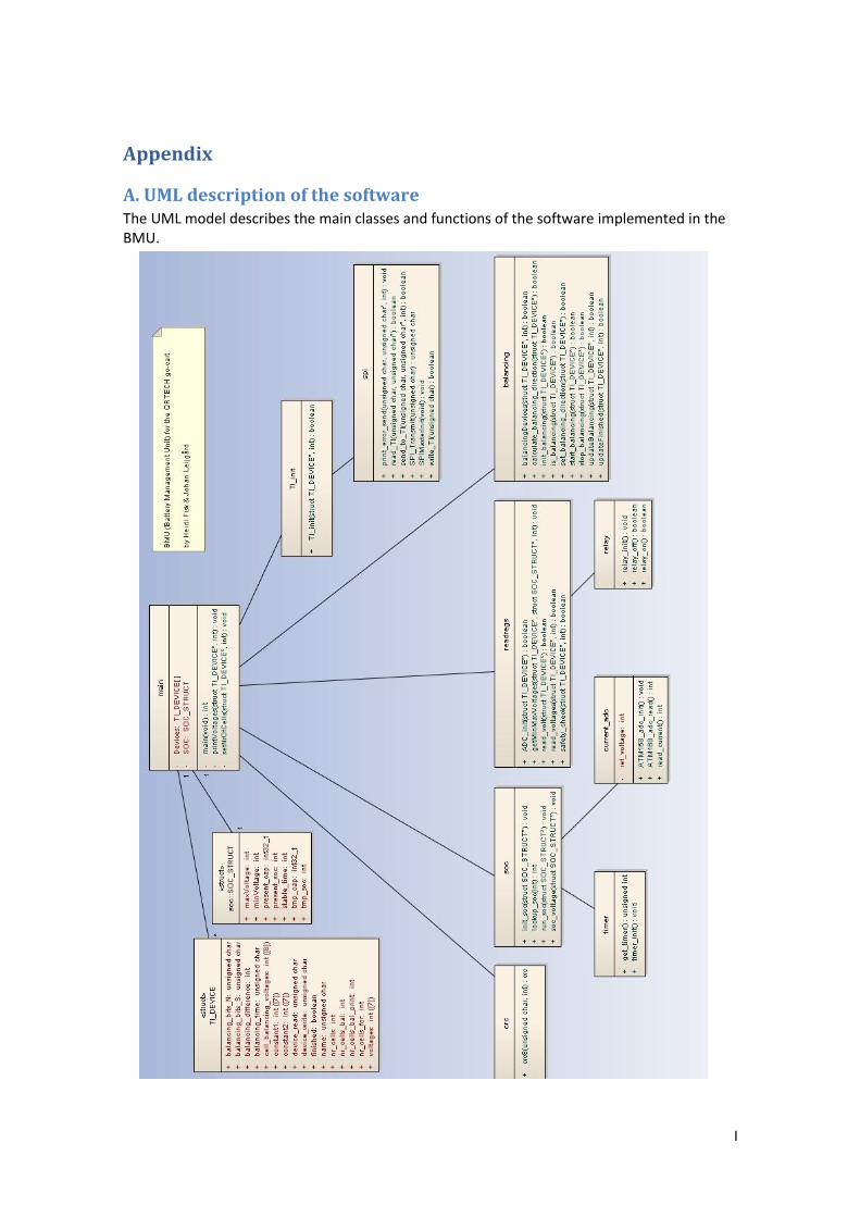
I
Appendix
A. UML description of the software The UML model describes the main classes and functions of the software implemented in the BMU.
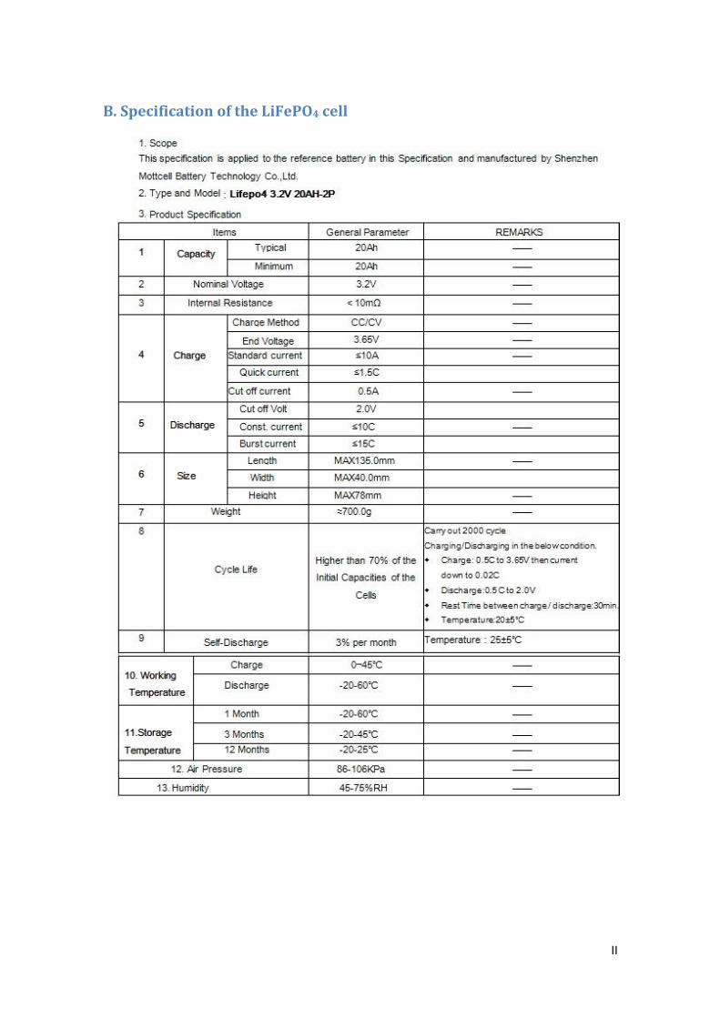
II
B. Specification of the LiFePO4 cell
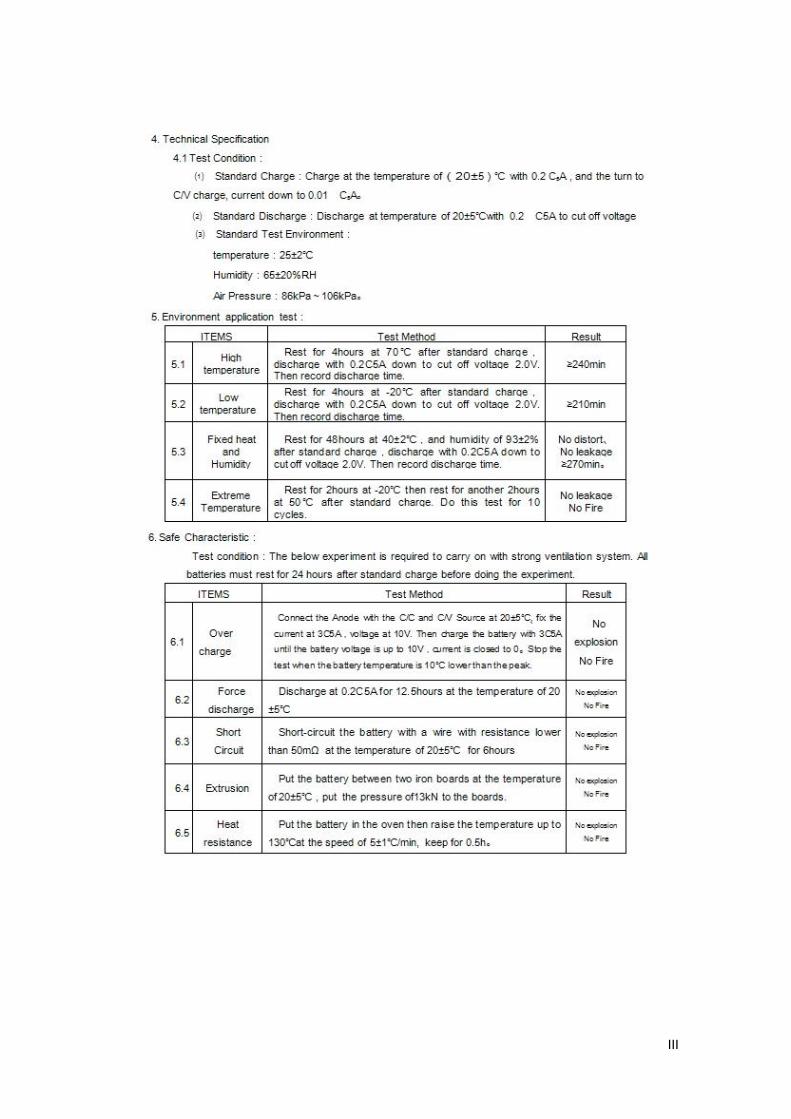
III

IV
Shenzhen Mottcell Battery Technology Co.,Ltd Model Number: 3.2V 20AH-2P Data sheet number: SM-QS-HW-90022, VERSION: A/0 Date: 2010-3-1 Tel +86-755-2230-6827 Http://www.mottcell.com, Email: [email protected]

V
C. List of battery companies
A123
An American battery company
http://www.a123systems.com/
ABATEL
A Swedish battery supplier
http://www.abatel.com
Enertech
An American battery company within Enerdel
http://www.enertechint.com/
EIG Battery
A Korean and American battery company
http://www.eigbattery.com/
European Batteries
A European battery company with a factory in Finland
http://www.europeanbatteries.com/solutions/cells
Life Batt
An American battery supplier
http://www.lifebatt.com/cellspecs.html
Peak Battery
An American battery supplier
http://www.peakbattery.com/index.html