Embed Size (px)
Citation preview
A 3D-PRINTED 1 MG LEGGED MICROROBOT RUNNING AT 15 BODY LENGTHS
PER SECOND Ryan St. Pierre1*, Walker Gosrich2, and Sarah Bergbreiter1
1 Department of Mechanical Engineering and the Institute for Systems Research, University of Maryland,
College Park, Maryland, USA 2Department of Mechanical and Aerospace Engineering, The State University of New York at Buffalo,
Buffalo, New York, USA
ABSTRACT
This work presents an experimental platform for studying the
locomotion of small-scale (<100 mg) legged microrobots. Robot
chassis were fabricated with microscale 3D printing and embedded
permanent magnets provide actuation. The design integrates a full
rotational friction bearing in the hip joint, capable of actuation up
to 150 Hz with no visible signs of wear after rotating at 100 Hz for
over 1,000,000 cycles. The robot presented in this work weighs 1
mg and is observed running at speeds up to 37.3 mm/s (14.9 body
lengths per second) providing initial insights on the dynamics of
legged locomotion at ant-scales.
INTRODUCTION Empirical biological scaling laws show an increase in relative
velocity (body length per second) with decreasing body mass [1].
However, as robots are scaled down, their relative speeds pale in
comparison to biological counterparts. An understanding of the
dynamics of legged locomotion at insect scales is needed to inform
design and control of microrobots. Large-scale robots, such as
RHex (7 kg) [2], provide a platform for understanding both the
morphology and control of legged locomotion. The large size of
RHex enables versatility and flexibility within the platform,
allowing design components, such as legs, to be changed easily.
By incorporating microscale 3D printing with magnetic actuation,
this work provides a versatile platform to study legged locomotion
of robots with a mass over 1,000,000 times smaller than RHex.
The final robot tested in this work is shown in Figure 1.
Making ant-scale microrobotics, specifically robots less than
100 mg in body mass, is an impressive feat in itself. One of the
more successful microrobots, an 80 mg thermally actuated
microrobot, presented in [3] used thermal actuation to raise and
lower legs. However, the stride length and stride frequency of this
robot was limited, showing top speeds up to 6 mm/s (0.8 body
lengths per second). The 10 mg solar powered microrobot
presented in [4] incorporated actuation, control, and power to
achieve a robot capable of autonomous movement, although not
appreciable forward propulsion. More recently, the walking robot
(18 mg) presented in [5] incorporated electrostatic actuators to
generate foot paths in vertical and horizontal directions and
demonstrated speeds up to 0.7mm/s (0.15 body lengths per
second).
These same microrobots can serve as physical models for
understanding milligram-scale legged locomotion. Legged robots
with lead zirconate titanate (PZT) were developed to investigate
the dynamics of contact interactions in microrobotic legs [6], with
more recent, similarly structured, legged microrobots weighing 4.4
g and 379 mg demonstrating walking at 0.06 body lengths per
second and 0.1 body lengths per second, respectively [7]. The 25
mg robot fabricated in [8] incorporated compliant materials to
create a microrobot with passively articulated legs. By taking
advantage of the passive degrees of freedom and incorporating
magnetic actuation this robot achieved top speeds of 5 body
lengths per second.
Similar to the experimental platform presented in [9], this
work takes advantage of 3D printing to create a chassis for a
legged robot. By incorporating permanent magnets as a form of
wireless actuation the mechanical aspects of legged locomotion
can be studied. Additionally, magnetic actuation provides insights
into the torque requirements as well as the mechanical power
required to achieve motion.
Figure 1: Fabricated 1 mg, 2.5 mm x 1.6 mm x 0.7 mm
quadrupedal microrobot pictured with a desiccated bullet ant head
(Paraponera clavata).
ROBOT DESIGN AND FABRICATION The robot design is similar to RHex [2] and the quadrupedal
robots presented in [9]. Each leg of the robot is shaped like a “C”,
providing a rolling contact with the ground. A friction bearing at
each hip enables a full rotary motion of the leg from the torque on
an embedded permanent magnet.
The microrobots were fabricated using direct laser writing for
3D printing at the microscale. The process is described in Figure 2.
A sacrificial layer of 20% dextran (Dextran 70 Sigma-Aldrich) was
spin-coated on to an ITO-coated glass slide (Nanoscribe) at 1,500
rpm for 1 minute (Figure 2A). The microrobot structure is
patterned using dip-in laser lithography (DiLL) with a Nanoscribe
Photonic Professional GT using the 25X objective (Carl Zeiss
Microscopy) and a negative tone photoresist (IP-S Nanoscribe).
After printing, the microrobots were developed in propylene glycol
monomethyl ether acetate (PGMEA) for 2 hours. The slide was
removed from the PGMEA bath and rinsed with isopropyl alcohol
(IPA) to wash away the PGMEA and excess photoresist. The
microrobots were released from the sacrificial layer by dissolving
the dextran with deionized (DI) water. The microrobots were then
978-1-940470-03-0/HH2018/$25©2018TRF 59 Solid-State Sensors, Actuators and Microsystems WorkshopHilton Head Island, South Carolina, June 3-7, 2018DOI 10.31438/trf.hh2018.16
placed in a bath of IPA and sonicated overnight in a heated bath
(3510 MTH Branson) to remove any excess photoresist in the
rotary joints of the robot. Once fully cleaned, 250 µm cube
magnets (C0005-10, SuperMagnetMan) were manually placed in
the hip joints and secured with cyanoacrylate (Loctite 401). The
final fabricated robot is shown in Figure 1. The orientation of the
dipoles of the embedded magnets mechanically programs the gait
for the microrobot. In this work, the dipoles were aligned in the
same direction, creating a pronking (4-legged hopping) gait.
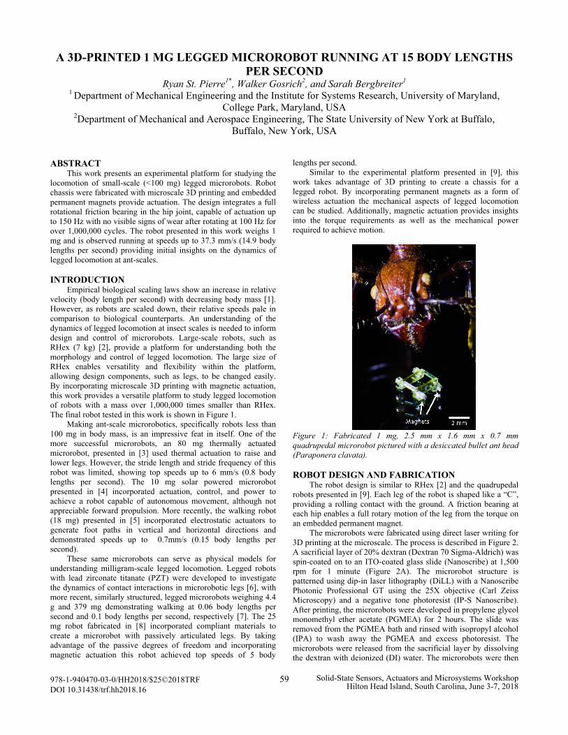
Figure 2: Fabrication process for direct laser writing and
embedded permanent magnets for actuation.
EXPERIMENTAL SETUP Robots were actuated in a custom-made two-axis Helmholtz
coil system, used to generate a two-dimensional rotating magnetic
field, providing a torque on the embedded magnets and actuating
the legs. A schematic of the interaction is shown in Figure 3. The
coil brackets are 3D printed (UPrint Plus SE Stratasys) and
wrapped with 22 gauge enameled magnet wire. The vertical coil
pair has a nominal diameter of 120 mm and 60 turns of wrapping,
while the horizontal pair has a nominal diameter of 160 mm and 50
turns of wrapping. To create a rotating magnetic field, each
channel of a 2-channel arbitrary function generator (AFG3022C
Tektronix) was connected to a current amplifier (TS200-0A Accel
Instruments). The output of each channel of the function generator
is set to balance the coils, creating a symmetric rotating field with
a magnitude of 0.78 mT. The dipole of the 250 µm cube magnets
was estimated from the volume and material of the magnets as 17.8
A-mm2. Using the point-dipole model in [10], the maximum
applied torque is calculated as
𝜏𝑚𝑎𝑥 = 𝜇0ℎ 𝑚𝑟. ( 1)
Where 𝜇0 is the is the magnetic permeability, 𝜇0 = 4π x 10-7 N/A2
(in vacuum), h is the magnetic field from the coil, and mr is the
magnetic dipole of the embedded permanent magnets. The
maximum applied torque was calculated as 13.8 µN-mm.
To track the motion of the robot, the robot was filmed in the
sagittal plane with a high-speed camera (Fastcam UX100) at 1,000
fps equipped with a macro lens (Zeiss Makro-Planar T* 2/100mm
ZF.2 Macro Lens). The field of view of the macro lens was
approximately 19 mm wide, accommodating 7.5 body lengths of
travel. The motion of the robot was tracked using markerless
tracking software (TEMA Image Systems).
Figure 3: The microrobot is actuated in a rotating magnetic field
(B), resulting in a torque applied to each of the embedded magnets
in the hip joints. The vertical and horizontal components of the
magnetic field are generated from each coil pair.
CHARACTERIZATION OF 3D PRINTED
ROTATIONAL BEARINGS Fully rotational microdevices are limited in their performance
by surface forces, such as friction, while solid-solid interfaces in
rotating parts often suffer from wear, further decreasing
performance. To minimize the effect of friction in rotary devices,
contact needs to be limited by either micro-ball bearings [11],
hydro-dynamic bearings [12], air bearings created through
magnetic or electrostatic suspension [13,14], or a liquid film
[15,16]. While most of these strategies require complex
manufacturing processes with tight tolerances, the bearings used in
this work were printed monolithically, requiring only a single
fabrication step. A solid model and photograph of the bearing is
shown in Figure 5.
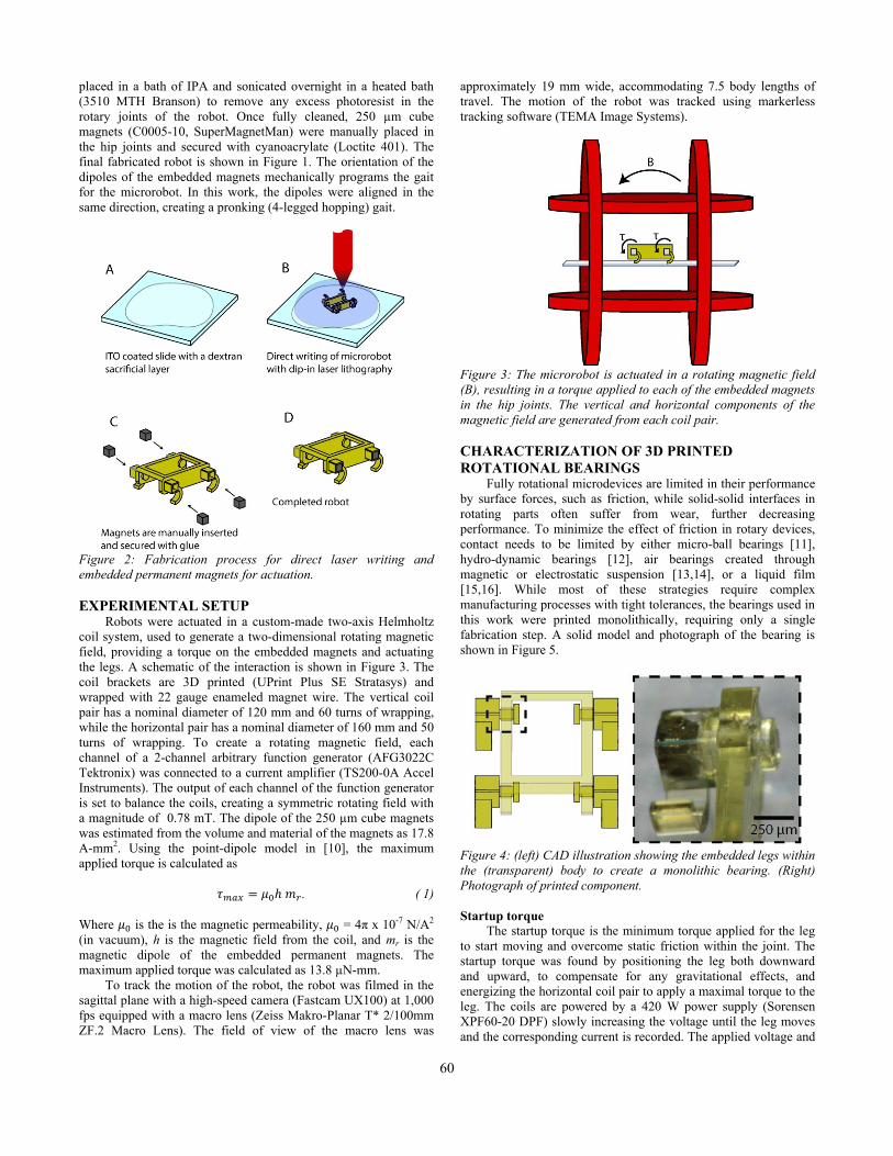
Figure 4: (left) CAD illustration showing the embedded legs within
the (transparent) body to create a monolithic bearing. (Right)
Photograph of printed component.
Startup torque
The startup torque is the minimum torque applied for the leg
to start moving and overcome static friction within the joint. The
startup torque was found by positioning the leg both downward
and upward, to compensate for any gravitational effects, and
energizing the horizontal coil pair to apply a maximal torque to the
leg. The coils are powered by a 420 W power supply (Sorensen
XPF60-20 DPF) slowly increasing the voltage until the leg moves
and the corresponding current is recorded. The applied voltage and
60
current to the coil is 1.63±0.02 V and 0.55±0.00 A, resulting in a
field of 0.31 mT, and a calculated start up torque of 5.47 µN-mm.
Actuation response
The robot was suspended without ground contact and actuated
from 10 Hz to 180 Hz in 10 Hz increments. High-speed video of
the leg rotating was recorded at 2,500 fps (Fastcam UX100) and
processed in markerless tracking software (TEMA Image Systems)
to determine the average rotational speed. Figure 5 shows the
average rotational speed of the leg as a function of the driving
frequency of the coil system. The leg rotation matches the
actuation frequency up to 150 Hz. At higher frequencies, the
rotation of the leg is no longer in sync with the rotating field.
Higher rotation frequencies can be achieved with a stronger
magnetic field or by reducing the friction in the joint, though
neither is explored here. A lumped parameter approximation of the
viscous damping can be estimated from [11],
𝜔𝑆−𝑂 =𝜏
𝑐 (2)
where 𝜔𝑆−𝑂 is the step-out frequency when the magnets are no
longer in sync, 𝜏 is the maximum applied torque, calculated from
eq. 1, and c is the viscous damping. The viscous damping in the
system was calculated as 13.7 µN-µm-s/rad.
Figure 5: The average rotational frequency of a leg of the
microrobot not in contact with the ground vs rotating magnetic
field frequency. The solid line represents the average and the
shaded area represents the standard deviation over more than five
rotations. The dashed line visualizes when the rotational frequency
of the leg is equal to the driving frequency.
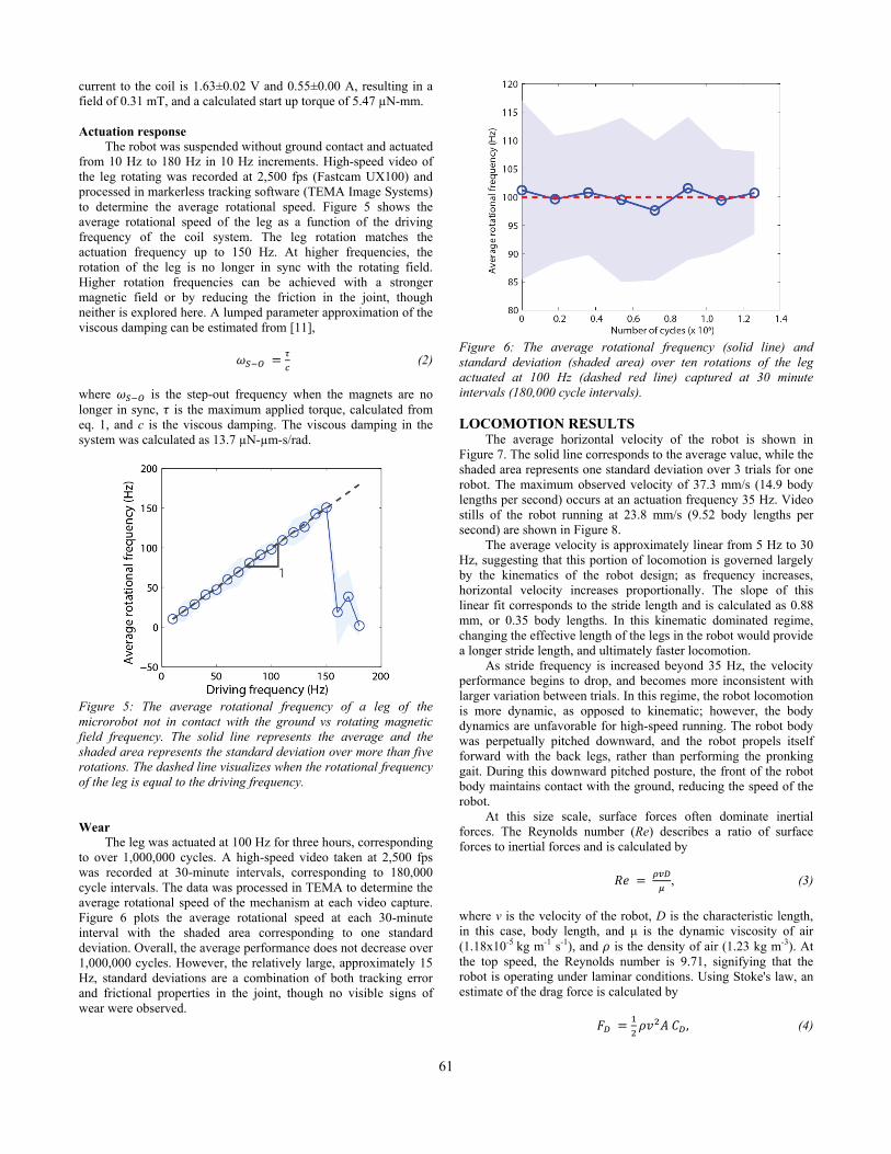
Wear
The leg was actuated at 100 Hz for three hours, corresponding
to over 1,000,000 cycles. A high-speed video taken at 2,500 fps
was recorded at 30-minute intervals, corresponding to 180,000
cycle intervals. The data was processed in TEMA to determine the
average rotational speed of the mechanism at each video capture.
Figure 6 plots the average rotational speed at each 30-minute
interval with the shaded area corresponding to one standard
deviation. Overall, the average performance does not decrease over
1,000,000 cycles. However, the relatively large, approximately 15
Hz, standard deviations are a combination of both tracking error
and frictional properties in the joint, though no visible signs of
wear were observed.
Figure 6: The average rotational frequency (solid line) and
standard deviation (shaded area) over ten rotations of the leg
actuated at 100 Hz (dashed red line) captured at 30 minute
intervals (180,000 cycle intervals).
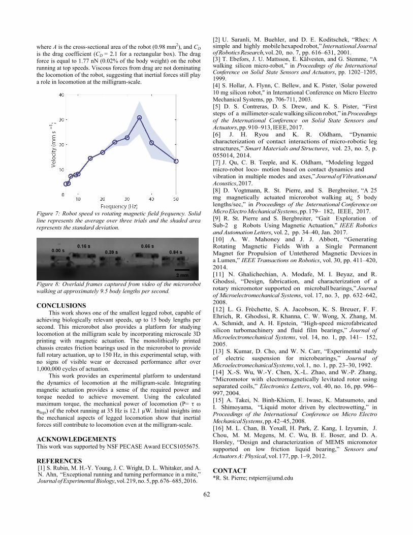
LOCOMOTION RESULTS The average horizontal velocity of the robot is shown in
Figure 7. The solid line corresponds to the average value, while the
shaded area represents one standard deviation over 3 trials for one
robot. The maximum observed velocity of 37.3 mm/s (14.9 body
lengths per second) occurs at an actuation frequency 35 Hz. Video
stills of the robot running at 23.8 mm/s (9.52 body lengths per
second) are shown in Figure 8.
The average velocity is approximately linear from 5 Hz to 30
Hz, suggesting that this portion of locomotion is governed largely
by the kinematics of the robot design; as frequency increases,
horizontal velocity increases proportionally. The slope of this
linear fit corresponds to the stride length and is calculated as 0.88
mm, or 0.35 body lengths. In this kinematic dominated regime,
changing the effective length of the legs in the robot would provide
a longer stride length, and ultimately faster locomotion.
As stride frequency is increased beyond 35 Hz, the velocity
performance begins to drop, and becomes more inconsistent with
larger variation between trials. In this regime, the robot locomotion
is more dynamic, as opposed to kinematic; however, the body
dynamics are unfavorable for high-speed running. The robot body
was perpetually pitched downward, and the robot propels itself
forward with the back legs, rather than performing the pronking
gait. During this downward pitched posture, the front of the robot
body maintains contact with the ground, reducing the speed of the
robot.
At this size scale, surface forces often dominate inertial
forces. The Reynolds number (Re) describes a ratio of surface
forces to inertial forces and is calculated by
𝑅𝑒 = 𝜌𝑣𝐷
𝜇, (3)
where v is the velocity of the robot, D is the characteristic length,
in this case, body length, and μ is the dynamic viscosity of air
(1.18x10⁻⁵ kg m-1 s-1), and 𝜌 is the density of air (1.23 kg m-3). At
the top speed, the Reynolds number is 9.71, signifying that the
robot is operating under laminar conditions. Using Stoke's law, an
estimate of the drag force is calculated by
𝐹𝐷 =1
2𝜌𝑣2𝐴 𝐶𝐷, (4)
61
where A is the cross-sectional area of the robot (0.98 mm2), and CD
is the drag coefficient (CD = 2.1 for a rectangular box). The drag
force is equal to 1.77 nN (0.02% of the body weight) on the robot
running at top speeds. Viscous forces from drag are not dominating
the locomotion of the robot, suggesting that inertial forces still play
a role in locomotion at the milligram-scale.
Figure 7: Robot speed vs rotating magnetic field frequency. Solid
line represents the average over three trials and the shaded area
represents the standard deviation.
Figure 8: Overlaid frames captured from video of the microrobot
walking at approximately 9.5 body lengths per second.
CONCLUSIONS This work shows one of the smallest legged robot, capable of
achieving biologically relevant speeds, up to 15 body lengths per
second. This microrobot also provides a platform for studying
locomotion at the milligram scale by incorporating microscale 3D
printing with magnetic actuation. The monolithically printed
chassis creates friction bearings used in the microrobot to provide
full rotary actuation, up to 150 Hz, in this experimental setup, with
no signs of visible wear or decreased performance after over
1,000,000 cycles of actuation.
This work provides an experimental platform to understand
the dynamics of locomotion at the milligram-scale. Integrating
magnetic actuation provides a sense of the required power and
torque needed to achieve movement. Using the calculated
maximum torque, the mechanical power of locomotion (P= τ ω
nlegs) of the robot running at 35 Hz is 12.1 µW. Initial insights into
the mechanical aspects of legged locomotion show that inertial
forces still contribute to locomotion even at the milligram-scale.
ACKNOWLEDGEMENTS This work was supported by NSF PECASE Award ECCS1055675.
REFERENCES [1] S. Rubin, M. H.-Y. Young, J. C. Wright, D. L. Whitaker, and A. N. Ahn, “Exceptional running and turning performance in a mite,” Journal of Experimental Biology, vol. 219, no. 5, pp. 676–685, 2016.
[2] U. Saranli, M. Buehler, and D. E. Koditschek, “Rhex: A simple and highly mobile hexapod robot,” International Journal of Robotics Research, vol. 20, no. 7, pp. 616–631, 2001. [3] T. Ebefors, J. U. Mattsson, E. Kalvesten, and G. Stemme, “A walking silicon micro-robot,” in Proceedings of the International Conference on Solid State Sensors and Actuators, pp. 1202–1205, 1999. [4] S. Hollar, A. Flynn, C. Bellew, and K. Pister, \Solar powered
10 mg silicon robot," in International Conference on Micro Electro
Mechanical Systems, pp. 706-711, 2003.
[5] D. S. Contreras, D. S. Drew, and K. S. Pister, “First
steps of a millimeter-scale walking silicon robot,” in Proceedings
of the International Conference on Solid State Sensors and
Actuators, pp. 910–913, IEEE, 2017.
[6] J. H. Ryou and K. R. Oldham, “Dynamic
characterization of contact interactions of micro-robotic leg
structures,” Smart Materials and Structures, vol. 23, no. 5, p.
055014, 2014.
[7] J. Qu, C. B. Teeple, and K. Oldham, “Modeling legged
micro-robot loco- motion based on contact dynamics and
vibration in multiple modes and axes,” Journal of Vibration and
Acoustics, 2017.
[8] D. Vogtmann, R. St. Pierre, and S. Bergbreiter, “A 25
mg magnetically actuated microrobot walking at¿ 5 body
lengths/sec,” in Proceedings of the International Conference on
Micro Electro Mechanical Systems, pp. 179– 182, IEEE, 2017.
[9] R. St. Pierre and S. Bergbreiter, “Gait Exploration of
Sub-2 g Robots Using Magnetic Actuation,” IEEE Robotics
and Automation Letters, vol. 2, pp. 34–40, Jan. 2017.
[10] A. W. Mahoney and J. J. Abbott, “Generating
Rotating Magnetic Fields With a Single Permanent
Magnet for Propulsion of Untethered Magnetic Devices in
a Lumen,” IEEE Transactions on Robotics, vol. 30, pp. 411–420,
2014.
[11] N. Ghalichechian, A. Modafe, M. I. Beyaz, and R.
Ghodssi, “Design, fabrication, and characterization of a
rotary micromotor supported on microball bearings,” Journal
of Microelectromechanical Systems, vol. 17, no. 3, pp. 632–642,
2008.
[12] L. G. Frechette, S. A. Jacobson, K. S. Breuer, F. F.
Ehrich, R. Ghodssi, R. Khanna, C. W. Wong, X. Zhang, M.
A. Schmidt, and A. H. Epstein, “High-speed microfabricated
silicon turbomachinery and fluid film bearings,” Journal of
Microelectromechanical Systems, vol. 14, no. 1, pp. 141– 152,
2005.
[13] S. Kumar, D. Cho, and W. N. Carr, “Experimental study
of electric suspension for microbearings,” Journal of
Microelectromechanical Systems, vol. 1, no. 1, pp. 23–30, 1992.
[14] X.-S. Wu, W.-Y. Chen, X.-L. Zhao, and W.-P. Zhang,
“Micromotor with electromagnetically levitated rotor using
separated coils,” Electronics Letters, vol. 40, no. 16, pp. 996–
997, 2004.
[15] A. Takei, N. Binh-Khiem, E. Iwase, K. Matsumoto, and
I. Shimoyama, “Liquid motor driven by electrowetting,” in
Proceedings of the International Conference on Micro Electro
Mechanical Systems, pp. 42–45, 2008.
[16] M. L. Chan, B. Yoxall, H. Park, Z. Kang, I. Izyumin, J.
Chou, M. M. Megens, M. C. Wu, B. E. Boser, and D. A.
Horsley, “Design and characterization of MEMS micromotor
supported on low friction liquid bearing,” Sensors and
Actuators A: Physical, vol. 177, pp. 1–9, 2012.
CONTACT *R. St. Pierre; [email protected]
62