Embed Size (px)
Citation preview

Feedback Control of a Legged Microrobot with On-Board Sensing
Remo Bruhwiler, Benjamin Goldberg, Neel Doshi, Onur Ozcan,Noah Jafferis, Michael Karpelson, and Robert J. Wood
Harvard University, John A. Paulson School of Engineering and Applied Sciences, Cambridge, MA, USA
Abstract— Full autonomy remains a challenge for miniaturerobotic platforms due to mass and size requirements of on-board power and control electronics. This paper presents asolution to these challenges with a 2.3g autonomous leggedrobot. An off-the-shelf optical mouse sensor is adapted foruse on the Harvard Ambulatory Microrobot (HAMR) byreducing the sensor weight by 36% and achieving a positionerror below 11% when suspended 3mm above a cardstocksurface. The position data is combined with data from agyroscope for feedback control of both position and orientation.A microcontroller processes the sensor data and commandsa controlled gait to HAMR that is powered by a battery, aboost converter and high voltage drive electronics. Solar cellsare used as an alternative source providing enough power forautonomous operation of the robot. The resulting deviation fora controlled straight-line walk using both sensors to minimizelateral deviation and angular error is only 4.6%, compared toan error of 31% in an uncontrolled, straight-line walk.
I. INTRODUCTION
Small crawling robots show great potential in applicationssuch as search and rescue, exploration of hazardous envi-ronments and infrastructure inspection. Inexpensive robotscould operate in large collectives performing missions thatare too dangerous for humans or require access to extremelyconfined spaces. Wireless and self controlled behavior is akey requirement for these applications.
Robots at larger scales such as the DASH robot [1]are able to carry on-board power and sensors but exceed20g and are more than 10cm long. Also at a larger scale,two optical mouse sensors were used for orientation andposition control of a wheeled robot [2] with feedback controlimplemented on-board using a microcontroller. Additionally,Fuchiwaki et al. confirmed that a combination of two opticalmouse sensors (they used the Avago ADNS-2051 sensor ina piezoelectric driven microrobot) provides robust data foraccurate path navigation [3]. Finally, a 10mg, solar powered,legged robot demonstrated open-loop locomotion in [4].
The legged microrobot used in this work is the Har-vard Ambulatory Microrobot (HAMR). The latest version,HAMR-VP, is 4.4 cm in length, weighs 1.27 g (withouton-board electronics and sensing) and has been shown tolocomote at speeds exceeding to 10 body lengths per second(44 cm/s) and carry payloads greater than its own bodyweight while tethered to off-board power supplies [5]. Previ-ous versions of HAMR have demonstrated on-board powerand voltage amplification to drive the piezoelectric actuators([6],[7]) but have lacked feedback control.
The desired sensor for motion control provides 2-D po-sition and angular heading state information for real-time
Fig. 1. HAMR-VP, modified to include on-board power, sensing andcontrol.
feedback control. An optical mouse sensor and a MEMSgyroscope are chosen as the most promising combination ofsensors and is integrated into the robot. An optical mousesensor provides position information relative to a startingpoint. Off-the-shelf optical mouse sensors such as the onedescribed in this paper have the additional advantage ofcoming pre-packaged with signal conditioning that performsthe optical flow calculations and provides velocity estimatesvia a standard communication protocol.
The complete system is shown in Fig.1 and a list ofthe mass of the components is presented in table I. Beforefeedback control is performed, the optical mouse sensoris characterized and the overall power requirements forthe robot are determined. Locomotion properties are theninvestigated at low and high frequencies in section III-B. Therobot is controlled with a PID controller described in sectionIV that varies the phase of all four lift actuators simultane-ously. Varying the leg phasing allows the control system tocommand turns as well as performing lateral maneuvers. Aminimum turning radius of 14 mm and maximum lateralspeed (perpendicular to the heading of the robot) of 1 cm/sis possible.
The robot presented in this paper is the first insect-scalerobot capable of on-board feedback control.
II. SENSOR CHARACTERIZATION
The basic principle of an optical mouse sensor is the samefor most packages and manufacturers. The beam comingfrom the sensor emitted by an LED reflects against theground. The reflections are magnified by a lens and captured
2015 IEEE/RSJ International Conference on Intelligent Robots and Systems (IROS)Congress Center HamburgSept 28 - Oct 2, 2015. Hamburg, Germany
978-1-4799-9993-4/15/$31.00 ©2015 IEEE 5727

TABLE IMASS OF HAMR-VP WITH ON-BOARD CONTROL, SENSING AND
POWER
Part WeightBase HAMR-VP from [5] 1270 mg
Control and Gyroscope Board 375 mgMouse Sensor Board 277 mg
Boost Converter Board 245 mgSolar Cells 75 mg
Glue and miscellaneous 58 mgAutonomous HAMR-VP 2.3 g
by an image sensor array. The sensor array passes theinformation to an on-board controller which calculates thedeviations in x and y directions by comparing successiveframes [8].
The main advantages of using an optical mouse are thatthe measurement is not subject to drift, they are low-cost,high precision, and have minimal computation requirements.
A. Optical Mouse Sensor for legged locomotion
Given the maximum payload carrying capacity of 1.35 gfrom [5], the weight limit for such a sensor must be in therange of a few hundred milligrams to be carried by the robotand allow for other power and control electronics. These tightpayload constraints favor a solution with only one opticalsensor. The “low power LED integrated slim mouse sensor”(Avago ADNS-3530) produced by Avago Technologies ischosen for position sensing due to the following benefits. Thesensor is one of the smallest optical mouse sensors availableon the market. In addition, it is a low power (3.6 mAactive and 0.04 mA resting at 3.3 V) optical navigationsensor with an automatic power management mode, makingit ideal for power-sensitive applications [9]. High speedmotion is possible since the device can operate at speeds of∼ 50 cm/s and accelerations of 8 g. In addition, it has an on-chip oscillator and an integrated LED to minimize externalcomponents. The chip itself is 12.9 mm in length, 9.6 mm inwidth and 1.69 mm in height; close to, but within the limitsof HAMR’s payload capacity.
Changes in position are measured by optically acquiringsequential surface images and mathematically determiningthe direction and magnitude of movements. The sensorcontains an image acquisition system, a digital signal pro-cessor (DSP) and a four wire serial port. Surface imagesare processed by the DSP to determine the direction anddistance of motion. This information can then be read bythe microcontroller from the sensor serial port.
B. Optical Mouse Sensor Characterization
To characterize the sensor, a 3D plotter with accuracy of± 50 µm (Shapeoko 2) is used to make specific translationalmovements in x-, y-, and z-directions over a white cardstocksurface with the sensor attached. The intention is to readdata from the sensor and compare it to the ground truthprovided by the commanded plotter movements. The plotteris programmed to produce a square path at varying heightsabove the ground. This distance can then be compared to the
0 20 40 60 80 100
0
20
40
60
80
100
X (mm)
Y (m
m)
Plotter TrajectorySensor Trajectory
Fig. 2. A measured square trajectory is compared to a reference trajectory.The dashed blue line represents the sensor reading, and the orange linerepresents the reference.
sensor distance and the accuracy of the sensor as a functionof distance from the ground can be determined. Accordingto the data sheet [9] the sensor accuracy degrades withincreasing distance between the sensor and the surface. SinceHAMR rolls and pitches during locomotion, the sensor errorat various distances is important to characterize. The sensoris moved in a square trajectory twice at each height andthen the vertical distance is increased by 1 mm to measureperformance at six different sensor heights.
An example measurement and reference trajectory arecompared in Fig. 2. The error is determined by the percentagedeviation of the upper right corner of the square. This isdetermined by computing the vector sum of the deviation ofthis point and dividing by the total distance traveled, in thiscase 20 cm in x direction and 20 cm in y direction.
Tests are performed at vertical distances of 1 mm up to6 mm. As expected, a larger distance between the lens andthe surface results in increased error as shown in Fig. 3.Based on the maximum roll and pitch rotations of 0.2 radiansas measured in [10], the sensor should be placed at a nominalheight of 1.5 mm in order to avoid hitting the ground. Therocking will result in a maximum height of approximately3 mm, which, based on these measurements and the sensorcharacterization in Fig.3, should allow the x and y positionsof HAMR to be estimated with an error of less than 10%.
The same characterization tests are conducted with themodified sensor board. To minimize the influence of theoptical components (such as alignment of the lens), themeasurements are taken on the exact same sensor board withsome passive parts (i.e. resistors and capacitors) manuallyremoved. The results of the tests are presented in Fig. 3.The percent path deviation of the original sensor board andthe modified board are nearly identical for vertical distancesbetween 1 mm and 5 mm. A large difference in performanceis visible at a distance of 6 mm. This is most likely dueto small differences in the test surface which can resultin large differences in the measured distance. However, forHAMR, the maximum anticipated sensor height is 3 mm, andtherefore the focus is on the region of 1 mm to 5 mm. In this
5728

1 1.5 2 2.5 3 3.5 4 4.5 5 5.5 60
20
40
60
80
100
Sensor Height (mm)
Path
Dev
iatio
n (%
)
With Passive ComponentsWithout Passive Components
Fig. 3. The path deviation as a funciton of height with (blue) and without(orange) passive components.
target region there is no significant difference between sensorboard with passive elements and without. As a result, futureversions of the sensor board are built without any additionalpassive elements.
C. Gyroscope on HAMR
A MEMS gyroscope (Invensense, MPU9150) is used inaddition to the optical mouse sensor to provide angular head-ing measurements. This sensor has been used and character-ized on a flapping wing micro air vehicle in prior work [11]but was limited to tethered operation. The implementationof the sensor in this paper is an on-board configuration thatcommunicates with a microcontroller (ATMEGA168).
The gyroscope utilized is a part of a 9-axis inertialmeasurement unit (IMU) which consists of a gyroscope, ac-celerometer, and magnetometer sensors on x, y, and z-axes.However, due to noise issues, the use of sensor informationother than gyroscope data is avoided for this version. Thesensor sends the raw gyroscope data to the microprocessorusing I2C bus, which is then filtered and integrated. Thefilter used is a simple, Savitzky-Golay type low pass filter.The filtered data is numerically integrated in order to findthe roll-pitch-yaw angles, and the orientation of the robot isthe yaw angle found with this integration.
The orientation measurements are not as accurate aspresented in [11]. The main reason behind this is the simplefilter that is implemented in this work. The filter in [11]is implemented on a computer running a real-time MatlabxPC operating system with built-in filter libraries; hence,there were few issues with the processing power. On HAMR,similar implementation is conducted on a microcontrollerwithout any built-in library and very limited processingpower. Using a better filter on the microcontroller wouldimprove the orientation estimation.
III. ON-BOARD POSITION SENSING
The optical mouse sensor board consists of a lens, theoptical mouse sensor and a supporting PCB. The integrationof these three components is discussed in this section withspecial attention paid to the weight-saving modifications.
A. Making the Sensor Lighter
To reduce unnecessary weight, sections of the base platecan be removed by laser micro-machining excess materialoff the PCB typically intended for mounting the sensor.Small sections of the PCB that contain vias and supportthe semiconductor elements will remain. The original sensorweight is reduced from 244 mg to 204 mg.
The “lens plate” consists of two crucial elements: Thefirst is a plastic molded illumination lens and the second isan imaging lens used for magnification. Those two elementsare located close to each other, covering the LED and thephoto array of the sensor. With a simple rectangle shaped cutprofile everything but those two elements can be removedand the original lens weight of 125 mg can be reduced to32 mg. Fig.4 shows the lens and sensor after these weightreduction steps.
A crucial part of making a light sensor board is designinga lightweight and sturdy PCB. The PCB supports the sensorand holds it in place under the robot providing reliableelectrical and mechanical contact.
TOP
BOTTOM
Control Board
Optical Mouse Sensor
Boost Converter
Ground Connection
Fig. 4. The optical mouse sensor including lens stack (bottom left). Theboard is connected mechanically on all four sides of the “X” shape tothe bottom of the robot and electrically with manually soldered wires tothe control board. The control board (top left) includes the microcontroller,gyroscope, programming ‘tail’, and electrical and mechanical connections tothe actuators. The boost converter board (top right) amplifies a low voltagesupply (e.g. from a battery or solar cells) to the 200V operating point for thepiezoelectric actuators. Electrical and mechanical ground connections to theactuators (bottom right). All boards are connected electrically by manuallysoldering individual strands of wire to the control board.
Fig. 4 presents the integration with the sensor board readyfor HAMR. After fabrication of the 37mg PCB, the opticalmouse sensor is soldered to the PCB using a reflow process.In a last step the protective covering on the lens is removedand the lens (after cutting away the unnecessary parts) isglued on top of the sensor above the LED and the photo
5729

array. This has to be done carefully as accurate alignment ofthe lens to the photo array is crucial for good sensor readings.The complete sensor board weighs 277mg and is shown inFig. 4.
B. Results with on-board sensing
The sensor board is then mounted to the bottom of HAMRby attaching the four arms of the ‘X’ shaped PCB to the twobottom composite rails of the robot with cyanacrolate glue.
For initial tests, the sensor is wired to an off-board Arduinofor computation and communication. The test setup in thiscase consists of two independent systems: One is the “robot”setup which includes HAMR, a computer controlling therobot, and a power source. The second system is the “sensor”system which consists of the sensor board, an Arduino, anda laptop to collect the data coming from the Arduino. Thosetwo systems are connected electrically via a tether to HAMR.The force imparted from the tether has a negligible effect onthe walking motion.
0 20 40 60 80 100 120 140−20
−15
−10
−5
0
X (mm)
Y (m
m)
SensorCamera
Fig. 5. A test walk of HAMR at 10Hz walking frequency with theattached sensor. Both lines represent the trajectory traveled by HAMR inbody coordinates.
The results from a walking test at 10Hz is shown in Fig. 5.Data from the sensor is plotted against data from an overheadcamera and vision tracking (Phantom v7.3 and Xcitex-ProAnalyst) with an accuracy of ±0.5mm. The tracking softwaredetermines the center of mass and orientation of the robotwhich are transformed into the body coordinates and areplotted in Fig. 5. The error in Fig. 5 can be calculated bycomparing error in the total distance in X and Y directionsbetween the sensor and the camera. For a trial with the robotrunning at a frequency of 10Hz, the cumulative, straight-lineerror is 10.22%. These results are consistent with the initialaccuracy estimations from the 3D plotter tests in section II-Bfor a sensor height between 3-4mm.
To determine if the walking frequency influences error,further tests are conducted. For example, the gait frequencycould influence rocking which would result in significant upand down movement of the lens relative to the surface. Asinvestigated in the previous sections, this difference in heightaffects the accuracy of the system. To understand how thespeed influences the error, two additional measurements areconducted at 20Hz and 30Hz. For the 20Hz test, an error
of approximately 8.28% was observed whereas the resultingerror of the 30Hz test was approximately 11.18%.
The first conclusion is that the sensor measurement isconsistently less than the camera measurement for all testedfrequencies. This indicates that the sensor “loses” data on theway. This might be because of the vertical movement of therobot; HAMR could be lifted out of the range of the sensorfor a short time during the step (too far away from ground)and could lose the distance traveled during this time. Thiserror is exacerbated by other sources of error including lenscontamination and surface imperfections.
The second and most important conclusion is that thesensor error is in the range of 8% to 11% which is sufficientfor use in HAMR position control. The error seems not to beinfluenced by the traveling speed of the robot. Furthermore,the sensor has to be mounted as close as possible to theground and while taking the walking motion of HAMR intoaccount (up and down movement of the sensor) a maximumerror between 8% to 11% is to be expected.
IV. FEEDBACK CONTROL ON HAMR
This section describes the integration of the optical mousesensor, a gyroscope, a microcontroller and power electronicsto control the actuators. The only connection to the robot isa four wire tether which provides power (200V as well as3.3V), a ground connection and a debugging wire. In Fig. 1,HAMR is shown with a top PCB that includes a controller(ATmega168), power electronics and a gyroscope (MPU-9150). The bottom PCB carries the optical mouse sensor.
A. Closed Loop Control of HAMR
Two manually tuned PID controllers (see Fig. 6) minimizethe error between the measured orientation and position andthe desired values.
PID Controller
Walk Signals
PID Controller
Power ElectronicsBody Dynamics
LateralVelocity
Micro Controller
Gyro
Mouse Sensor
Σ
Fig. 6. Schematic of the on-board control loop. Both sensors provide datawhich are fed into the microcontroller (right) resulting in drive signals tothe actuators.
The feedback controller takes the measured angle andlateral deviation as well as both desired values into accountand calculates the resulting orientation phase and ‘crabbing’(lateral) phase. The orientation phase and crab phases areadded to the nominal gait phasing. These updated valuesare then read by the signal generation block to achieve thedesired path. The actuator drive scheme and leg phasing
5730

TABLE IILEG PHASING FOR ORIENTATION AND LATERAL CONTROL
Leg Nominal LiftPhase w.r.t Swing
Orientationoc
Lateral Posi-tion lc
Front Left 90◦ +φ1 +φ2Front Right 90◦ −φ1 −φ2Rear Right 90◦ −φ1 +φ2Rear Left 90◦ +φ1 −φ2
for turning is explained in detail in [5]. The commandedsignal phase for each leg is controlled independently and iscalculated as the following: φ = 90◦ + oc + lc with oc andlc defined in table II. The two independent PID controllersupdate φ1 and φ2 of table II as defined in equations (1) and(2).
φ1 = Korp eor +Kor
d
d
dteor +Kor
i
∫eor (1)
φ2 = Klatp elat +Klat
d
d
dtelat +Klat
i
∫elat (2)
where K{or,lat}p ,K
{or,lat}d ,K
{or,lat}i are PID gains for the
orientation and lateral controllers and eor and elat areorientation and lateral errors, respectively.
The control loop executes functions including walkingand updating variables such as sensor values and controlcommands. The only function which is executed in everyiteration is the signal generation, (block “Walk Signals” inFig. 6) which runs at 1kHz and takes the most recent outputof the PID controller as an input and defines the required legphases based on table II to achieve the desired trajectory.
The sensor readings must be limited below their maximumbandwidth to achieve a walking frequency of 10 Hz giventhe choice of microcontroller. For example, the position mea-surement from the optical mouse sensor is updated at 100 Hz,the gyroscope is updated at 25 Hz, and the control values(corrections to the nominal gait phasing) are updated at ∼3 Hz. The presented update rates are experimentally found tobe the minimum update rates required for accurate trajectoryfollowing at 10 Hz leg actuation. One main considerationis that the gyroscope takes significantly longer to updatecompared to the the control commands or the optical mousesensor values since the signal must be filtered and integratedto obtain the robot heading. However, if the update doesn’ttake place regularly, the angular error increases drastically.
B. Straight trajectories
Performing a straight walk is possible when feedbackcontrol with both sensors is used. The lateral deviation aswell as the angle of the robot relative to the desired trajectoryare minimized. With an overhead camera, a high speedvideo of HAMR is taken while performing a straight linewalk (Phantom v7.3). A second trial for an uncontrolledwalk is performed to compare both deviations from thedesired trajectory. The two videos are then processed with avideo tracking software (Xcitex-Pro Analyst) to extract thetrajectory of the center of mass.
0 20 40 60 80 100 120 140 160 180 200 220−60
−50
−40
−30
−20
−10
0
X (mm)
Y (m
m)
Controlled WalkUncontrolled Walk
Fig. 7. Results of tracking the center of mass of the robot. The line in blueshows the path of HAMR performing a controlled walk and the orange lineallows a comparison with an uncontrolled walk.
Fig. 7 shows the tracked center of mass for controlledand uncontrolled motions starting at the origin with an angleof zero degrees between the robot and the x-axis. HAMRperforms a straight walk for 200mm. This results in anerror of 4.6% lateral deviation for the controlled case incomparison to 31% path error for an uncontrolled walk.
The explanation for the error in an uncontrolled walklikely lies in asymmetric mechanics. For example, if onetransmission swings or lifts slightly more than the others, thiscan result in small but constant crabbing and turning motions.These accumulating errors can be verified by investigatingthe lateral deviation and heading angle presented in Fig. 7.
Errors arising from walk mechanics can be minimized withthe two sensors and the presented feedback controller. Thereason for the closed-loop error of 4.6% is likely due toimperfections in the sensors. In the controlled walk, both thelateral and orientation errors are zero at the end of the walkwhen observed through the debugging line. This indicatesthat an error in the angle as well as in the lateral deviationhas developed without being measured by the sensors. Mostlikely this is due to noise, slow update rates, drift in the IMU,and the fact that both “lose measurements” as described insection II-B where the error increases if the sensor is notclose enough to the ground.
0 20 40 60 80 100 120 140 160 180 200−20
−15
−10
−5
0
5
10
15
20
X (mm)
Ang
le (d
eg)
Controlled WalkUncontrolled Walk
Fig. 8. The angle of the robot for the uncontrolled walk (orange) andcontrolled case (blue).
5731
A robust minimization of the heading deviation is difficultdue to the characteristics of the gyroscope. First, a filter hasto be applied to extract reliable data from the noisy readings.Second, an integration of the angular velocity in the mainloop can result in poor estimation because a) the update ratemight not be fast enough (ideally the gyroscope should beread at 1kHz or higher), b) the shaking and rocking motionsof HAMR might affect readings and c) the gyroscope’sinherent drift in time. Therefore it is challenging to extractone resulting angle in the z direction only. Nevertheless theestimated angle of the gyroscope was used in the feedbackloop and roughly minimized (see Fig. 8). This resulted in anoscillation around the x axis which is closer to a straight walkthan a constantly increasing angular error when uncontrolled.The RMS error of the heading in the trial shown in figure 8for the controlled walk is 3.6% compared to 6.3% in the theuncontrolled walk.
V. ON-BOARD POWER
On-board power is a crucial element of autonomy. First,the power consumption must be analyzed in order to evaluatepossible supply or storage mechanisms. Those sources mustmatch the requirements of HAMR, including a weight limitof approximately 1.35g for all additional systems includingsensing and control.
Two sources, a battery (“GM300910” from PowerStream)and solar cells (“ELO solar cells 1-6615-8” from MicoLinkDevices) are successfully tested for this HAMR version. Thesame boost converter works in both cases.
A. Power Consumption
The power consumption is a critical factor for an on-boardpower supply as the source, which has to meet the demandand at the same time not degrade walking significantly. Aninvestigation is conducted to determine the power require-ments of the robot by measuring the voltage and the currentfor the 3V line and the 200V line separately. With thosemeasurements, a total power consumption is determined.
0 50 100 150 200 250 300 350 400−0.4
−0.3
−0.2
−0.1
0
0.1
0.2
0.3
Time (ms)
Pow
er (W
)
200V Source3V Source
Fig. 9. Power of HAMR when walking. The orange line is the powerconsumption of the high voltage line (primarily due to actuators and powerelectronics) and the blue is the 3V supply (mainly controller and sensors).
Fig. 9 shows the resulting plot of both power measure-ments. As expected, both plots reveal a certain periodicity
for a gait frequency of around 6 to 7Hz. Averaging overthe power consumption of the low voltage line results in22.0mW. Doing the same for the high voltage part revealsthat a supply has to meet 60.1mW to power the 200V line fora total of 82.1mW average power consumption. Consideringthe fact that higher peak power is needed (as can be seenin Fig. 9) and the efficiency of the boost converter (72% atmaximum according to [12]) has to be taken into account,this 82.1mW is a rough approximation of the minimal powerrequirements.
B. Power Source
Two power sources are considered for this prototype: Abattery and solar cells. Batteries have already been success-fully used for previous HAMR versions in [7], howeverbatteries have the drawback of low energy density resultingin short lifetime and/or large relative mass. The tests in [7]successfully demonstrated walking at an actuation frequencyof 20Hz for two minutes using a 330mg, 8mAh lithiumpolymer battery (“GM300910” from PowerStream).
Recent advances in solar cell fabrication has increased theefficiency (up to 30%) for very thin-film cells. The solarcells in a 2S3P configuration can provide up to 240mWwith a very bright flashlight (“The Torch” from WickedLasers) 6 inches above the cells, or approximately four Sun’sof luminosity. Tests have shown that currents of around47mA at a voltage of 5V are achieved in these conditions.These specifications fit well with the power requirements andpayload capacity of HAMR with an overall weight of 75mgand an area of 19mm in length and 12mm in width.
C. Boost Converter
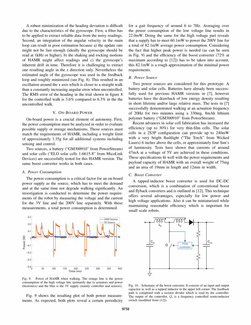
A tapped-inductor boost converter is used for DC-DCconversion, which is a combination of conventional boostand flyback converters and is outlined in [12]. This techniqueoffers several advantages, especially for low power andhigh voltage applications. Also it can be miniaturized whilemaintaining reasonable efficiency which is important forsmall scale robots.
Fig. 10. Schematic of the boost converter. It consists of an input and outputcapacitor as well as a tapped inductor in the upper left corner. The feedbackpath is completed with a resistor divider which is read by the controller.The output of the controller, Q, is a frequency controlled semiconductorswitch (modified from [12]).
5732
During a typical switching cycle, the switch Q (see Fig.10) is turned on, and current builds up in the primary winding(marking LP ). As Q is turned off, the energy stored inthe magnetic core is discharged to the high voltage outputthrough both windings. In this manner the capacitor, CHV , ischarged. To control the output voltage a controller is neededwhich modulates the switching frequency. This is representedby the blue “PFM controller” block in Fig. 10. The output ismonitored using a resistor divider and an analog comparator.If the voltage falls beneath a certain level a switching cycleis initiated delivering energy to the output capacitor and theload.
D. On-Board Power ResultsWith the 8mAh battery a HAMR can walk for approx-
imately 3 minutes. During this time all sensors were onand reading continuously. Furthermore both microcontrollers(one on the control board and one in the power converter)were running. Having a separate microcontroller for the boostconversion allows the sensor and leg controller to maintainthe same gait frequency and sensor accuracy.
An alternative to the use of batteries is depicted in Fig.1. The solar cells were demonstrated to provide sufficientpower to autonomously actuate HAMR’s legs. Feedbackcontrol tests, however, were unable to be performed dueto the heat of the light source which warped the cells andelectrical connections and did not allow enough time for theexperiments to be conducted. As the cells are significantlylighter than the batteries, though, it is feasible to carrymore than six cells and operate in reduced intensity light;eventually this can allow HAMR to perform a controlledwalk, even on a cloudy day.
VI. CONCLUSION
A 2.3g autonomous device with control and sensing abil-ities is presented. Sensing both angle and position of therobot provides the ability for path control; for example, astraight line walk is successfully demonstrated. The sensordata is sufficient for this application, although faster andbetter filtered readings from the gyroscope can improvethe heading control accuracy. A detailed investigation ofposition data offered by the optical mouse sensor showedgood accuracy and robustness to HAMR’s walking dynamics.The on-board control of the robot successfully minimized theerrors in angle and lateral deviation with the provided sensordata. On-board power can be provided by either a battery orsolar cells feeding a DC-DC converter. With all of thesesystems on-board, HAMR is able to sense and control thepath autonomously. Future work will investigate new controlstrategies for arbitrary trajectory following, wireless com-munication and additional sensing capabilities. Furthermore,custom integrated circuits (similar to those in [13]) will beinvestigated to achieve lower component weights and fastersensing and actuation frequencies.
VII. ACKNOWLEDGMENTS
The authors would like to thank all Harvard MicroroboticsLaboratory group members for their invaluable discussions.
This work is partially funded by the Wyss Institute forBiologically Inspired Engineering and the National ScienceFoundation. This material is based upon work supportedby the National Science Foundation Graduate Research Fel-lowship under Grant Number DGE1144152. Any opinion,findings, and conclusions or recommendations expressed inthis material are those of the authors and do not necessarilyreflect the views of the National Science Foundation.
REFERENCES
[1] P. Birkmeyer, K. Peterson, and R. S. Fearing, “Dash: A dynamic 16ghexapedal robot.” IEEE, 2009, pp. 2683–2689.
[2] J. Cooney, W. Xu, and G. Bright, “”Visual dead-reckoning for motioncontrol of a Mecanum-wheeled mobile robot”,” MECHATRONICS,vol. 14, no. 6, pp. 623–637, JUL 2004.
[3] O. Fuchiwaki, N. Tobe, H. Aoyama, D. Misaki, and T. Usuda,“Automatic micro-indentation and inspection system by piezo drivenmicro robot with multiple inner sensors,” in 2005 IEEE InternationalConference on Mechatronics and Automations, Vols 1-4, ConferenceProceedings, Gu, J and Liu, PX, Ed. IEEE, 2005.
[4] S. Hollar, A. Flynn, C. Bellew, and K. Pister, “Solar powered 10 mgsilicon robot,” in Micro Electro Mechanical Systems, 2003. MEMS-03 Kyoto. IEEE The Sixteenth Annual International Conference on.IEEE, 2003, pp. 706–711.
[5] A. T. Baisch, O. Ozcan, B. Goldberg, D. Ithier, and R. J. Wood, “Highspeed locomotion for a quadrupedal microrobot,” The InternationalJournal of Robotics Research, p. 0278364914521473, 2014.
[6] M. Karpelson, B. H. Waters, B. Goldberg, B. Mahoney, O. Ozcan,A. Baisch, P.-M. Meyitang, J. R. Smith, and R. J. Wood, “A wirelesslypowered, biologically inspired ambulatory microrobot,” in Roboticsand Automation (ICRA), 2014 IEEE International Conference on.IEEE, 2014, pp. 2384–2391.
[7] A. T. Baisch, C. Heimlich, M. Karpelson, and R. J. Wood, “HAMR3:An Autonomous 1.7g Ambulatory Robot,” in Intelligent Robots andSystems (IROS), 2011 IEEE/RSJ International Conference on. IEEE,2011, pp. 5073–5079.
[8] D. Sekimori and F. Miyazaki, “”Precise Dead-Reckoning for MobileRobots using Multiple Optical Mouse Sensors”,” Springer Nether-lands, vol. 76, no. 2, pp. 145–151, 2007.
[9] Avago Technologies Inc., “ADNS-3530 Optical Mouse Sensor DataSheet,” www.avago.com, 2014.
[10] B. F. Seitz, B. Goldberg, N. Doshi, O. Ozcan, D. L. Christensen, E. W.Hawkes, M. R. Cutkosky, and R. J. Wood, “Bio-inspired mechanismsfor inclined locomotion in a legged insect-scale robot,” in 2014 IEEEInternational Conference on Robotics and Biomimetics (ROBIO) ,December 5-10, 2014, Bali, Indonesia, 2014, pp. 791–796.
[11] S. Fuller, A. Sands, A. Haggerty, M. Karpelson, and R. Wood,“Estimating attitude and wind velocity using biomimetic sensors on amicrorobotic bee,” in 2013 IEEE International Conference on Roboticsand Automation (ICRA), 2013 2013, Conference Paper, pp. 1374–80, 2013 IEEE International Conference on Robotics and Automation(ICRA), 6-10 May 2013, Karlsruhe, Germany.
[12] M. Karpelson, G.-Y. Wei, and R. J. Wood, “Driving high voltagepiezoelectric actuators in microrobotic applications,” SENSORS ANDACTUATORS A-PHYSICAL, vol. 176, pp. 78–89, APR 2012.
[13] X. Zhang, M. Lok, T. Tong, S. Chaput, S. K. Lee, B. Reagen, H. Lee,D. Brooks, and G.-Y. Wei, “A multi-chip system optimized for insect-scale flapping-wing robots.”
5733