Embed Size (px)
Citation preview
HAL Id: hal-00714370https://hal.archives-ouvertes.fr/hal-00714370
Submitted on 8 Jan 2013
HAL is a multi-disciplinary open accessarchive for the deposit and dissemination of sci-entific research documents, whether they are pub-lished or not. The documents may come fromteaching and research institutions in France orabroad, or from public or private research centers.
L’archive ouverte pluridisciplinaire HAL, estdestinée au dépôt et à la diffusion de documentsscientifiques de niveau recherche, publiés ou non,émanant des établissements d’enseignement et derecherche français ou étrangers, des laboratoirespublics ou privés.
Control of a Magnetic Microrobot Navigating inMicrofluidic Arterial Bifurcations through Pulsatile and
Viscous FlowKarim Belharet, David Folio, Antoine Ferreira
To cite this version:Karim Belharet, David Folio, Antoine Ferreira. Control of a Magnetic Microrobot Navigating inMicrofluidic Arterial Bifurcations through Pulsatile and Viscous Flow. IEEE/RSJ International Con-ference on Intelligent Robots and Systems (IROS’2012), Oct 2012, Vilamoura, Algarve, Portugal.pp.2559-2564, �10.1109/IROS.2012.6386030�. �hal-00714370�
Control of a Magnetic Microrobot Navigating in Microfluidic ArterialBifurcations through Pulsatile and Viscous Flow
Karim Belharet, David Folio and Antoine Ferreira
Abstract— Navigating in bodily fluids to perform targeteddiagnosis and therapy has recently raised the problem ofrobust control of magnetic microrobots under real endovascularconditions. Various control approaches have been proposedin the literature but few of them have been experimentallyvalidated. In this paper, we point out the problem of navigationcontrollability of magnetic microrobots in high viscous fluidsand under pulsatile flow for endovascular applications. Weconsider the experimental navigation along a desired trajectory,in a simplified millimeter-sized arterial bifurcation, operating influids at the low-Reynolds-number regime where viscous dragsignificantly dominates over inertia. Different viscosity envi-ronments are tested under a systolic pulsatile flow compatiblewith heart beating. The control performances in terms tracking,robustness and stability are then experimentally demonstrated.
I. INTRODUCTION
Recent developments of microelectromechanical systems(MEMS) make possible to fabricate untethered biomedicalmicrorobots that can be injected intravenously to accom-plish targeted drug delivery tasks. Benefiting from theirsmall size and biocompatible properties, swimming micro-robots are able to reach and function within regions thatare unsuitable for traditional devices, which make them agood choice for controlled drug delivery microrobot. Mostof swimming approaches consequently rely upon magneticfields to wirelessly transmit power to the microrobot. Thisproof-of-concept was first studied using electromagnets [1]and superconducting magnets [2], [3] in phantom devices.Rapidly, magnetic manipulation of therapeutic ferromagneticnanoparticles (magnetic drug delivery) has progressed fromanimal to human clinical trials for shallow targets. It iscurrently limited to static magnets as yet there is no activefeedback control in this arena. Recently, magnetic micro-robots have received a lot of attention since they are able toprovide large motion forces and move in liquid environmentswith very low (less than one) Reynolds number environment(i.e., the ratio of inertial force to viscous force). Magneticpropulsion and steering for ferromagnetic microparticles,also has been employed [4] in which the magnetic forceand torque of a microrobot were induced independently byMaxwell and Helmhotz coil fields [5], [6]. Magnetic helicalmedical microrobots, inspired by the propulsion of bacterialflagella, are promising for use in open fluids for destroyingkidney stones in real human body [4], or for surgery inophtalmic procedures [7], [8]. Finally, magnetotactic bacteria
The authors are with the Laboratoire PRISME, Ecole NationaleSuperieure d’Ingenieurs de Bourges, 88 Bld Lahitolle, F-18020 Bourges;France. E-mail: {firstName.Name}@ensi-bourges.fr
actuated thanks to embedded or attached ferromagnetic mate-rial has been demonstrated [9]. All these contributions pointout the problem of navigation controllability of magneticmicrorobots in high viscous fluids and under pulsatile flowwhen experimental endovascular applications are considered.Recently, a new approach referred to as magnetic resonancenavigation has been proposed to steer and track in real timeendovascular magnetic carriers in deep tissues to target areasof interest [10]. As it focuses on in-vivo feasibility studiesof the microrobot pulling concept, developed model is linear[11] and in turn the synthesis of control laws relies onlinear PID approaches. Authors in [12] report instabilitiesand important oscillations around the equilibrium, especiallywhen the blood stream is modeled as a pulsatile flow. Theexperiments figure out a lack of robustness to noise andunmodeled dynamics. To overcome these limitations, weanalyze in this study a magnetic microrobot body navi-gating within a microfluidic chip under real physiologicalconditions. We consider the experimental navigation along adesired trajectory, in a simplified arterial bifurcation geom-etry, operating in fluids at the low-Reynolds-number regimewhere viscous drag significantly dominates over inertia. Dif-ferent viscosity environments are tested (ranging from 100%water-to-100% glycerol) under a systolic pulsatile flow. Wedemonstrate experimentally that the generalized predictivecontroller (GPC), developed previously in [13], is sufficientlyrobust against nonlinear model uncertainties (e.g. drag forceand viscosity), external perturbations (systolic pulsatile flow)and noisy trajectory tracking measurements.
This paper is organized as follows. First, Section II intro-duces an experimental setup that is used to operate magneticmicrorobots in microfluidic arterial bifurcations. Section 3provides an overview of the physics of control of a micro-robot using generalized predictive control (GPC) strategy.Section 4 presents experiments to illustrate the efficiency androbustness of the predictive navigation control approach w.r.t.different viscous medium and pulsatile flows. Finally, Section5 discusses the advantages of the predictive navigation andsome limitations related to the complexity of endovascularstructure network. This paper is concluded in Section 6.
II. EXPERIMENTAL SETUPA. Magnetic Setup
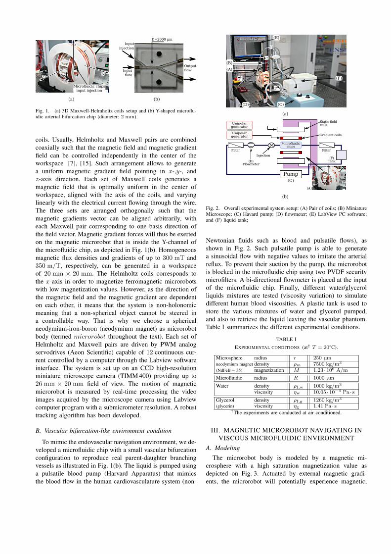
The experimental setup used to generate the 3D controlledmagnetic fields is shown in Fig. 1(a) and has been devel-oped specifically for the experiments (AeonScientificTM ,ETH Zurich) [14]. The system consists of three nestedsets of Maxwell coils and one nested set of Helmholtz
(a) (b)
Fig. 1. (a) 3D Maxwell-Helmholtz coils setup and (b) Y-shaped microflu-idic arterial bifurcation chip (diameter: 2 mm).
coils. Usually, Helmholtz and Maxwell pairs are combinedcoaxially such that the magnetic field and magnetic gradientfield can be controlled independently in the center of theworkspace [7], [15]. Such arrangement allows to generatea uniform magnetic gradient field pointing in x-,y-, andz-axis direction. Each set of Maxwell coils generates amagnetic field that is optimally uniform in the center ofworkspace, aligned with the axis of the coils, and varyinglinearly with the electrical current flowing through the wire.The three sets are arranged orthogonally such that themagnetic gradients vector can be aligned arbitrarily, witheach Maxwell pair corresponding to one basis direction ofthe field vector. Magnetic gradient forces will thus be exertedon the magnetic microrobot that is inside the Y-channel ofthe microfluidic chip, as depicted in Fig. 1(b). Homogeneousmagnetic flux densities and gradients of up to 300 mT and350 m/T, respectively, can be generated in a workspaceof 20 mm × 20 mm. The Helmholtz coils corresponds tothe x-axis in order to magnetize ferromagnetic microrobotswith low magnetization values. However, as the direction ofthe magnetic field and the magnetic gradient are dependenton each other, it means that the system is non-holonomicmeaning that a non-spherical object cannot be steered ina controllable way. That is why we choose a sphericalneodymium-iron-boron (neodymium magnet) as microrobotbody (termed microrobot throughout the text). Each set ofHelmholtz and Maxwell pairs are driven by PWM analogservodrives (Aeon Scientific) capable of 12 continuous cur-rent controlled by a computer through the Labview softwareinterface. The system is set up on an CCD high-resolutionminiature microscope camera (TIMM 400) providing up to26 mm × 20 mm field of view. The motion of magneticmicrorobot is measured by real-time processing the videoimages acquired by the microscope camera using Labviewcomputer program with a submicrometer resolution. A robusttracking algorithm has been developed.
B. Vascular bifurcation-like environment condition
To mimic the endovascular navigation environment, we de-veloped a microfluidic chip with a small vascular bifurcationconfiguration to reproduce real parent-daughter branchingvessels as illustrated in Fig. 1(b). The liquid is pumped usinga pulsatile blood pump (Harvard Apparatus) that mimicsthe blood flow in the human cardiovasculature system (non-
(a)
(b)
Fig. 2. Overall experimental system setup: (A) Pair of coils; (B) MiniatureMicroscope; (C) Havard pump; (D) flowmeter; (E) LabView PC software;and (F) liquid tank;
Newtonian fluids such as blood and pulsatile flows), asshown in Fig. 2. Such pulsatile pump is able to generatea sinusoidal flow with negative values to imitate the arterialreflux. To prevent their suction by the pump, the microrobotis blocked in the microfluidic chip using two PVDF securitymicrofilters. A bi-directional flowmeter is placed at the inputof the microfluidic chip. Finally, different water/glycerolliquids mixtures are tested (viscosity variation) to simulatedifferent human blood viscosities. A plastic tank is used tostore the various mixtures of water and glycerol pumped,and also to retrieve the liquid leaving the vascular phantom.Table I summarizes the different experimental conditions.
TABLE IEXPERIMENTAL CONDITIONS (at† T = 20°C).
Microsphere radius r 250 µmneodymium magnet density ρm 7500 kg/m3
(NdFeB – 35) magnetization M 1.23 · 106 A/m
Microfluidic radius R 1000 µm
Water density ρf,w 1000 kg/m3
viscosity ηw 10.05 · 10−4 Pa · s
Glycerol density ρf,g 1260 kg/m3
(glycerin) viscosity ηg 1.41 Pa · s†The experiments are conducted at air conditioned.
III. MAGNETIC MICROROBOT NAVIGATING INVISCOUS MICROFLUIDIC ENVIRONMENT
A. ModelingThe microrobot body is modeled by a magnetic mi-
crosphere with a high saturation magnetization value asdepicted on Fig. 3. Actuated by external magnetic gradi-ents, the microrobot will potentially experience magnetic,
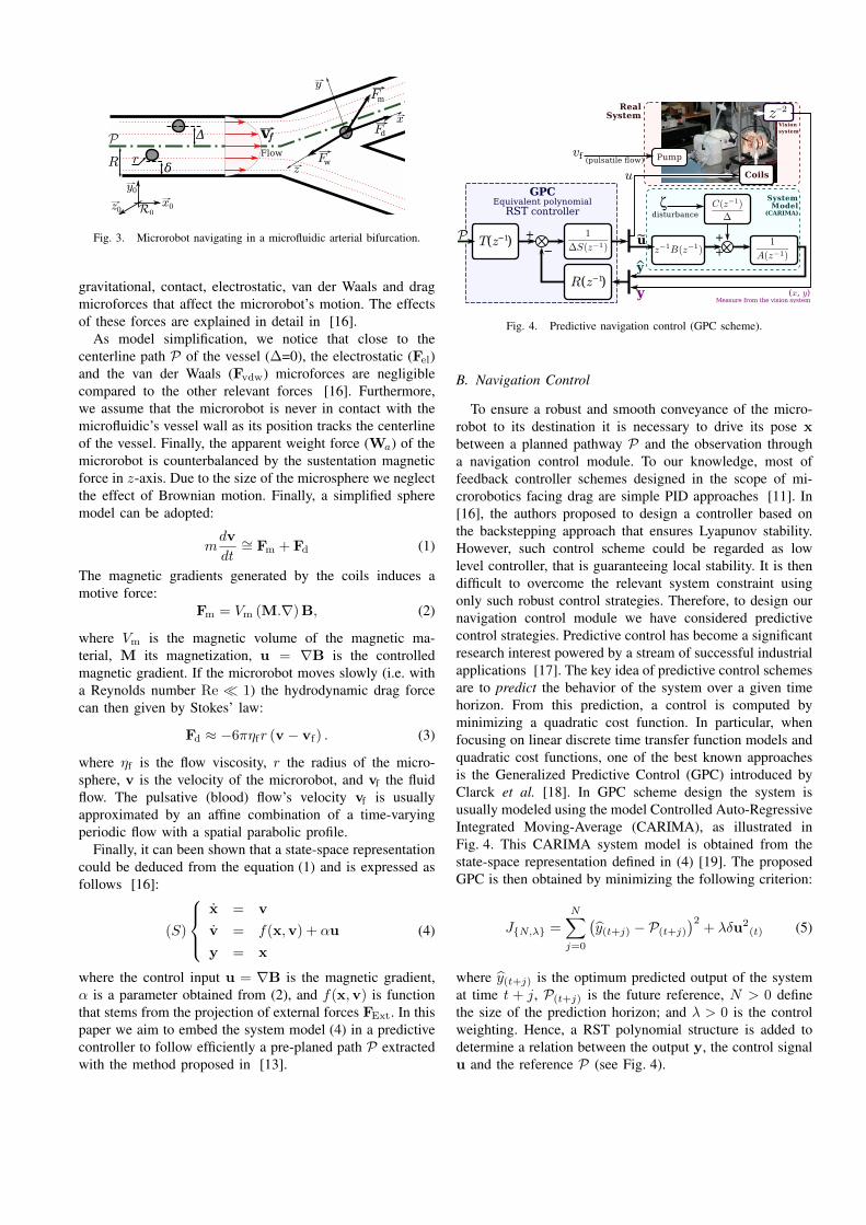
Fig. 3. Microrobot navigating in a microfluidic arterial bifurcation.
gravitational, contact, electrostatic, van der Waals and dragmicroforces that affect the microrobot’s motion. The effectsof these forces are explained in detail in [16].
As model simplification, we notice that close to thecenterline path P of the vessel (∆=0), the electrostatic (Fel)and the van der Waals (Fvdw) microforces are negligiblecompared to the other relevant forces [16]. Furthermore,we assume that the microrobot is never in contact with themicrofluidic’s vessel wall as its position tracks the centerlineof the vessel. Finally, the apparent weight force (Wa) of themicrorobot is counterbalanced by the sustentation magneticforce in z-axis. Due to the size of the microsphere we neglectthe effect of Brownian motion. Finally, a simplified spheremodel can be adopted:
mdv
dt∼= Fm + Fd (1)
The magnetic gradients generated by the coils induces amotive force:
Fm = Vm (M.∇)B, (2)
where Vm is the magnetic volume of the magnetic ma-terial, M its magnetization, u = ∇B is the controlledmagnetic gradient. If the microrobot moves slowly (i.e. witha Reynolds number Re � 1) the hydrodynamic drag forcecan then given by Stokes’ law:
Fd ≈ −6πηfr (v − vf) . (3)
where ηf is the flow viscosity, r the radius of the micro-sphere, v is the velocity of the microrobot, and vf the fluidflow. The pulsative (blood) flow’s velocity vf is usuallyapproximated by an affine combination of a time-varyingperiodic flow with a spatial parabolic profile.
Finally, it can been shown that a state-space representationcould be deduced from the equation (1) and is expressed asfollows [16]:
(S)
x = v
v = f(x,v) + αu
y = x
(4)
where the control input u = ∇B is the magnetic gradient,α is a parameter obtained from (2), and f(x,v) is functionthat stems from the projection of external forces FExt. In thispaper we aim to embed the system model (4) in a predictivecontroller to follow efficiently a pre-planed path P extractedwith the method proposed in [13].
Fig. 4. Predictive navigation control (GPC scheme).
B. Navigation Control
To ensure a robust and smooth conveyance of the micro-robot to its destination it is necessary to drive its pose xbetween a planned pathway P and the observation througha navigation control module. To our knowledge, most offeedback controller schemes designed in the scope of mi-crorobotics facing drag are simple PID approaches [11]. In[16], the authors proposed to design a controller based onthe backstepping approach that ensures Lyapunov stability.However, such control scheme could be regarded as lowlevel controller, that is guaranteeing local stability. It is thendifficult to overcome the relevant system constraint usingonly such robust control strategies. Therefore, to design ournavigation control module we have considered predictivecontrol strategies. Predictive control has become a significantresearch interest powered by a stream of successful industrialapplications [17]. The key idea of predictive control schemesare to predict the behavior of the system over a given timehorizon. From this prediction, a control is computed byminimizing a quadratic cost function. In particular, whenfocusing on linear discrete time transfer function models andquadratic cost functions, one of the best known approachesis the Generalized Predictive Control (GPC) introduced byClarck et al. [18]. In GPC scheme design the system isusually modeled using the model Controlled Auto-RegressiveIntegrated Moving-Average (CARIMA), as illustrated inFig. 4. This CARIMA system model is obtained from thestate-space representation defined in (4) [19]. The proposedGPC is then obtained by minimizing the following criterion:
J{N,λ} =
N∑j=0
(y(t+j) − P(t+j)
)2+ λδu2
(t) (5)
where y(t+j) is the optimum predicted output of the systemat time t + j, P(t+j) is the future reference, N > 0 definethe size of the prediction horizon; and λ > 0 is the controlweighting. Hence, a RST polynomial structure is added todetermine a relation between the output y, the control signalu and the reference P (see Fig. 4).
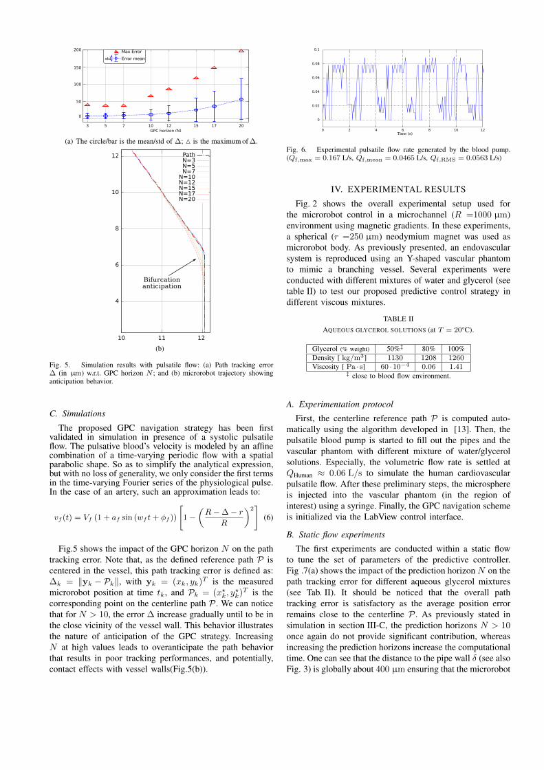
(a) The circle/bar is the mean/std of ∆; M is the maximum of ∆.
(b)
Fig. 5. Simulation results with pulsatile flow: (a) Path tracking error∆ (in µm) w.r.t. GPC horizon N ; and (b) microrobot trajectory showinganticipation behavior.
C. Simulations
The proposed GPC navigation strategy has been firstvalidated in simulation in presence of a systolic pulsatileflow. The pulsative blood’s velocity is modeled by an affinecombination of a time-varying periodic flow with a spatialparabolic shape. So as to simplify the analytical expression,but with no loss of generality, we only consider the first termsin the time-varying Fourier series of the physiological pulse.In the case of an artery, such an approximation leads to:
vf (t) = Vf (1 + af sin (wf t+ φf ))
[1 −
(R− ∆ − r
R
)2]
(6)
Fig.5 shows the impact of the GPC horizon N on the pathtracking error. Note that, as the defined reference path P iscentered in the vessel, this path tracking error is defined as:∆k = ‖yk − Pk‖, with yk = (xk, yk)T is the measuredmicrorobot position at time tk, and Pk = (x?k, y
?k)T is the
corresponding point on the centerline path P . We can noticethat for N > 10, the error ∆ increase gradually until to be inthe close vicinity of the vessel wall. This behavior illustratesthe nature of anticipation of the GPC strategy. IncreasingN at high values leads to overanticipate the path behaviorthat results in poor tracking performances, and potentially,contact effects with vessel walls(Fig.5(b)).
Fig. 6. Experimental pulsatile flow rate generated by the blood pump.(Qf,max = 0.167 L/s, Qf,mean = 0.0465 L/s, Qf,RMS = 0.0563 L/s)
IV. EXPERIMENTAL RESULTS
Fig. 2 shows the overall experimental setup used forthe microrobot control in a microchannel (R =1000 µm)environment using magnetic gradients. In these experiments,a spherical (r =250 µm) neodymium magnet was used asmicrorobot body. As previously presented, an endovascularsystem is reproduced using an Y-shaped vascular phantomto mimic a branching vessel. Several experiments wereconducted with different mixtures of water and glycerol (seetable II) to test our proposed predictive control strategy indifferent viscous mixtures.
TABLE IIAQUEOUS GLYCEROL SOLUTIONS (at T = 20°C).
Glycerol (% weight) 50%‡ 80% 100%Density [ kg/m3] 1130 1208 1260Viscosity [ Pa · s] 60 · 10−4 0.06 1.41
‡ close to blood flow environment.
A. Experimentation protocol
First, the centerline reference path P is computed auto-matically using the algorithm developed in [13]. Then, thepulsatile blood pump is started to fill out the pipes and thevascular phantom with different mixture of water/glycerolsolutions. Especially, the volumetric flow rate is settled atQHuman ≈ 0.06 L/s to simulate the human cardiovascularpulsatile flow. After these preliminary steps, the microsphereis injected into the vascular phantom (in the region ofinterest) using a syringe. Finally, the GPC navigation schemeis initialized via the LabView control interface.
B. Static flow experiments
The first experiments are conducted within a static flowto tune the set of parameters of the predictive controller.Fig .7(a) shows the impact of the prediction horizon N on thepath tracking error for different aqueous glycerol mixtures(see Tab. II). It should be noticed that the overall pathtracking error is satisfactory as the average position errorremains close to the centerline P . As previously stated insimulation in section III-C, the prediction horizons N > 10once again do not provide significant contribution, whereasincreasing the prediction horizons increase the computationaltime. One can see that the distance to the pipe wall δ (see alsoFig. 3) is globally about 400 µm ensuring that the microrobot
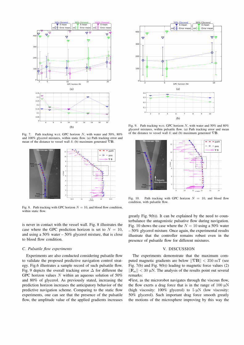
(a)
(b)
Fig. 7. Path tracking w.r.t. GPC horizon N , with water and 50%, 80%and 100% glycerol mixtures, within static flow. (a) Path tracking error andmean of the distance to vessel wall δ; (b) maximum generated ∇B.
Fig. 8. Path tracking with GPC horizon N = 10, and blood flow condition,within static flow.
is never in contact with the vessel wall. Fig. 8 illustrates thecase where the GPC prediction horizon is set to N = 10,and using a 50% water – 50% glycerol mixture, that is closeto blood flow condition.
C. Pulsatile flow experiments
Experiments are also conducted considering pulsatile flowto validate the proposed predictive navigation control strat-egy. Fig.6 illustrates a sample record of such pulsatile flow.Fig. 9 depicts the overall tracking error ∆ for different theGPC horizon values N within an aqueous solution of 50%and 80% of glycerol. As previously stated, increasing theprediction horizon increases the anticipatory behavior of thepredictive navigation scheme. Comparing to the static flowexperiments, one can see that the presence of the pulsatileflow, the amplitude value of the applied gradients increases
(a)
(b)
Fig. 9. Path tracking w.r.t. GPC horizon N , with water and 50% and 80%glycerol mixtures, within pulsatile flow. (a) Path tracking error and meanof the distance to vessel wall δ; and (b) maximum generated ∇B.
Fig. 10. Path tracking with GPC horizon N = 10, and blood flowcondition, with pulsatile flow.
greatly Fig. 9(b)). It can be explained by the need to coun-terbalance the antagonistic pulsative flow during navigation.Fig. 10 shows the case where the N = 10 using a 50% water– 50% glycerol mixture. Once again, the experimental resultsillustrate that the controller remains robust even in thepresence of pulsatile flow for different mixtures.
V. DISCUSSION
The experiments demonstrate that the maximum com-puted magnetic gradients are below ||∇B|| < 350 mT (seeFig. 7(b) and Fig. 9(b)) leading to magnetic force values (2)||Fm|| < 30 µN. The analysis of the results point out severalremarks:•First, as the microrobot navigates through the viscous flow,the flow exerts a drag force that is in the range of 100 µN(high viscosity: 100% glycerol) to 5 µN (low viscosity:50% glycerol). Such important drag force smooth greatlythe motions of the microsphere improving by this way the
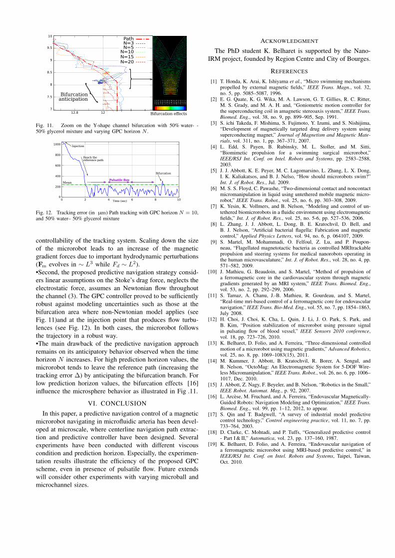
Fig. 11. Zoom on the Y-shape channel bifurcation with 50% water- -50% glycerol mixture and varying GPC horizon N .
Fig. 12. Tracking error (in µm) Path tracking with GPC horizon N = 10,and 50% water– 50% glycerol mixture
controllability of the tracking system. Scaling down the sizeof the microrobot leads to an increase of the magneticgradient forces due to important hydrodynamic perturbations(Fm evolves in ∼ L3 while Fd ∼ L2).•Second, the proposed predictive navigation strategy consid-ers linear assumptions on the Stoke’s drag force, neglects theelectrostatic force, assumes an Newtonian flow throughoutthe channel (3). The GPC controller proved to be sufficientlyrobust against modeling uncertainties such as those at thebifurcation area where non-Newtonian model applies (seeFig. 11)and at the injection point that produces flow turbu-lences (see Fig. 12). In both cases, the microrobot followsthe trajectory in a robust way.•The main drawback of the predictive navigation approachremains on its anticipatory behavior observed when the timehorizon N increases. For high prediction horizon values, themicrorobot tends to leave the reference path (increasing thetracking error ∆) by anticipating the bifurcation branch. Forlow prediction horizon values, the bifurcation effects [16]influence the microsphere behavior as illustrated in Fig .11.
VI. CONCLUSION
In this paper, a predictive navigation control of a magneticmicrorobot navigating in microfluidic arteria has been devel-oped at microscale, where centerline navigation path extrac-tion and predictive controller have been designed. Severalexperiments have been conducted with different viscouscondition and prediction horizon. Especially, the experimen-tation results illustrate the efficiency of the proposed GPCscheme, even in presence of pulsatile flow. Future extendswill consider other experiments with varying microball andmicrochannel sizes.
ACKNOWLEDGMENT
The PhD student K. Belharet is supported by the Nano-IRM project, founded by Region Centre and City of Bourges.
REFERENCES
[1] T. Honda, K. Arai, K. Ishiyama et al., “Micro swimming mechanismspropelled by external magnetic fields,” IEEE Trans. Magn., vol. 32,no. 5, pp. 5085–5087, 1996.
[2] E. G. Quate, K. G. Wika, M. A. Lawson, G. T. Gillies, R. C. Ritter,M. S. Grady, and M. A. H. and, “Goniometric motion controller forthe superconducting coil in amagnetic stereoaxis system,” IEEE Trans.Biomed. Eng., vol. 38, no. 9, pp. 899–905, Sep. 1991.
[3] S. ichi Takeda, F. Mishima, S. Fujimoto, Y. Izumi, and S. Nishijima,“Development of magnetically targeted drug delivery system usingsuperconducting magnet,” Journal of Magnetism and Magnetic Mate-rials, vol. 311, no. 1, pp. 367–371, 2007.
[4] L. Edd, S. Payen, B. Rubinsky, M. L. Stoller, and M. Sitti,“Biomimetic propulsion for a swimming surgical microrobot,”IEEE/RSJ Int. Conf. on Intel. Robots and Systems, pp. 2583–2588,2003.
[5] J. J. Abbott, K. E. Peyer, M. C. Lagomarsino, L. Zhang, L. X. Dong,I. K. Kaliakatsos, and B. J. Nelso, “How should microrobots swim?”Int. J. of Robot. Res., Jul. 2009.
[6] M. S. S. Floyd, C. Pawashe, “Two-dimensional contact and noncontactmicromanipulation in liquid using untethered mobile magnetic micro-robot,” IEEE Trans. Robot., vol. 25, no. 6, pp. 303–308, 2009.
[7] K. Yesin, K. Vollmers, and B. Nelson, “Modeling and control of un-tethered biomicrorobots in a fluidic environment using electromagneticfields,” Int. J. of Robot. Res., vol. 25, no. 5-6, pp. 527–536, 2006.
[8] L. Zhang, J. J. Abbott, L. Dong, B. E. Kratochvil, D. Bell, andB. J. Nelson, “Artificial bacterial flagella: Fabrication and magneticcontrol,” Applied Physics Letters, vol. 94, no. 6, p. 064107, 2009.
[9] S. Martel, M. Mohammadi, O. Felfoul, Z. Lu, and P. Poupon-neau, “Flagellated magnetotactic bacteria as controlled MRItrackablepropulsion and steering systems for medical nanorobots operating inthe human microvasculature,” Int. J. of Robot. Res., vol. 28, no. 4, pp.571–582, 2009.
[10] J. Mathieu, G. Beaudoin, and S. Martel, “Method of propulsion ofa ferromagnetic core in the cardiovascular system through magneticgradients generated by an MRI system,” IEEE Trans. Biomed. Eng.,vol. 53, no. 2, pp. 292–299, 2006.
[11] S. Tamaz, A. Chanu, J.-B. Mathieu, R. Gourdeau, and S. Martel,“Real-time mri-based control of a ferromagnetic core for endovascularnavigation,” IEEE Trans. Bio-Med. Eng., vol. 55, no. 7, pp. 1854–1863,July 2008.
[12] H. Choi, J. Choi, K. Cha, L. Quin, J. Li, J. O. Park, S. Park, andB. Kim, “Position stabilization of microrobot using pressure signalin pulsating flow of blood vessel,” IEEE Sensors 2010 conference,vol. 18, pp. 723–726, 2010.
[13] K. Belharet, D. Folio, and A. Ferreira, “Three-dimensional controlledmotion of a microrobot using magnetic gradients,” Advanced Robotics,vol. 25, no. 8, pp. 1069–1083(15), 2011.
[14] M. Kummer, J. Abbott, B. Kratochvil, R. Borer, A. Sengul, andB. Nelson, “OctoMag: An Electromagnetic System for 5-DOF Wire-less Micromanipulation,” IEEE Trans. Robot., vol. 26, no. 6, pp. 1006–1017, Dec. 2010.
[15] J. Abbott, Z. Nagy, F. Beyeler, and B. Nelson, “Robotics in the Small,”IEEE Robot. Automat. Mag., p. 92, 2007.
[16] L. Arcese, M. Fruchard, and A. Ferreira, “Endovascular Magnetically-Guided Robots: Navigation Modeling and Optimization,” IEEE Trans.Biomed. Eng., vol. 99, pp. 1–12, 2012, to appear.
[17] S. Qin and T. Badgwell, “A survey of industrial model predictivecontrol technology,” Control engineering practice, vol. 11, no. 7, pp.733–764, 2003.
[18] D. Clarke, C. Mohtadi, and P. Tuffs, “Generalized predictive control- Part I & II,” Automatica, vol. 23, pp. 137–160, 1987.
[19] K. Belharet, D. Folio, and A. Ferreira, “Endovascular navigation ofa ferromagnetic microrobot using MRI-based predictive control,” inIEEE/RSJ Int. Conf. on Intel. Robots and Systems, Taipei, Taiwan,Oct. 2010.