Embed Size (px)
Citation preview
NASA-CR-169920 19830010948
9950-774
DOE/JPL 954355/81-21 Distribution Category UC-63
Mobil Tyco Solar Energy Corporation 16 Hickory Drive
Waltham, Massachusetts 02154
LARGE AREA SILICON SHEET BY EFG
Program Manager: Juris P. Kalejs
Final Report - Subcontract No. 954355
Covering Period: October 29, 1975 - December 31, 1981
Distribution Date: September 15,.1992
"The JPL Flat Plate Solar. Array Project is sponsored by the U.S. Department of Energy and forms part of the Solar Photovol taic Conversion Program to initiate a maj or effort toward the development of flat plate solar arrays. This work was performed for the Jet Propulsion Laboratory, California Institute of Technology by agreement between NASA and DOE."
1111111111111 1111 1111111111111111111111111111 NF02588
(
https://ntrs.nasa.gov/search.jsp?R=19830010948 2018-11-15T19:21:48+00:00Z
/'
DISPLAY 83N19219/2
.; ,
JPL-9950-774 DOE/JPL-954355-81/21 NAS 1.26: 169920 O(\("'CC ~ n\1Ld UNCLASSIFIED DOCUMENT
RPT*: NASA-CR-169920 CNT*: JPL-954355
lJITL: l_arse ar~ea ~31 ! 1 cor~ ~3r"iee1 t)';l EFt; {)ec;: t 9;3l
TLSP: Fina! Reportl 29 Ort. 1975
A~.JT;~: A.lK:ALE·.J:3, 'J: p~ CORP: Mobil Tyco Solar Energy COfP. l Walthaml Mass. Jet Propulsion Lab. I
C:a l i fCirrd a Sponsored in part by DO~ prepared for JPLl
SAP: He A~)5/i:;'lF H(}"1 n ,-Loa: 1.-:-=
MAJS: I*CRYSTAL GROWTH/*FLAT PLATES/*R1880NS/*SILICON/~THIN FILMS f\l I r~j:=; ~ './ FCJRr\lA(=E:3./ :3(JLAR ARRA \.:'S./ :=;~)BSTRATES A8A~ Hi.) tt-1() r ABS~ Work carried out on lne JPL Flat Plate Solar"Array Project, for the
purpose of developing a metnod for silicon ribbon production by Edge-defined Film-fed Growth l~tG) for use as low-cost substrate materIal in terrestrial solar rpJl m~nufacture, IS described. A multiple rIbbon furnace unit that is designea to operate on a continuous basis tor perl odS of at least one week, with melt replenishment and automatic flbbon width contraIl and to produce silicon Sheet at a rate of one square meter per hour, was constructed, Prog~am mt !estones set for single flDoon furnace operation to demonstrate basic EEG system capabilities Wilh respect to growth speed, thickness and cell performance were achieved for 10 cm wide
DOE/JPL 954355/91-21 Distribution Category UC-63
Mobil Tyco Solar Energy Corporation 16 Hickory Drive
Waltham, Massachusetts 02254
LARGE AREA SILICON SHEET BY EFG
Program Manager: Juris P. Kalejs
Final Report - Subcontract No. 954355
Covering Period: October 29, 1975 - December 31, 1981
Distribution Date: September 15, 1982
"The JPL Flat Plate Solar Array Proj ect is sponsored by the U. S. Department of Energy and forms part of the Solar Photovoltaic Conversion Program to initiate a major effort toward the development of flat plate solar arrays. This work was performed for the Jet Propuls ion Laboratory, Cal ifornia Institute of Technology by agreement between NASA and DOE."

Intentionally Left Blank
This report describes work carried out on the JPL Flat Plate Solar Array Project under the sponsorship of the U.S. Department of Energy for the purpose of developing a method for silicon ribbon production by Edge-defined Film-fed Growth (EFG) for use as low-cost substrate material in terrestrial solar cell manufacture. The program was funded over a period of more than six years, from October 1975 to December 1981, to a level of $4.6 million dollars. The program has culminated in the construction of a multiple ribbon furnace unit that is designed to operate on a continuous basis for periods of at least one week, with melt replenishment and automatic ribbon width control, and to produce silicon sheet at a rate of one square meter per hour.
Program milestones set for single ribbon furnace operation to demonstrate basic EFG system capabilities with respect to growth speed, thickness and cell performance were achieved for 10 cm wide ribbon: steady-state growth at 4 cm/min and 200 ~m thickness over period~ of an hour and longer was made routine, and a small area (-~ cm ) cell efficiency of 13+~ demonstrated. Large area () 50 cm-) cells of average efficiency of 10 to 11~, with peak values of 11 to 12~ were also achieved. However, at the program's conclusion, the integration of these individual performance levels into multiple ribbon furnace operation, as demanded by the interim Technical Features Demonstration goals for 1980, was not accomplished.
The performance level of the multiple ribbon furnace in many areas has been very successful in spite of the fact that the Technical Features Demonstration requirements were not all fulfilled at the end of the contract period. Full implementation of automatic ribbon width control systems and continuous melt replenishment were achieved. This has allowed one operator to grow four 10 cm wide ribbons in run lengths of 10 to 15 hours and demonstrate significant periods of simultaneous growth of four ribbons at full width. Shortfalls in performance have occurred mainly in an inability to consistently and reproducibly achieve acceptable growth conditions that result in homogeneous ribbon of required quality. This has contributed to depressing average cell performance to the range of 9-10~ efficiency at the best in the multiple furnace operational mode.
At this point, the shortfalls in performance and material quality levels cannot be attributed to specific causes. A lack of flexibility in optimizing growth conditions may be a central element in contributing to deficiencies in both of these areas. This situation arises because of a relatively high capillary rise
iii
distance for this design of furnace. which then limits the range for operating variables that is available during growth initiation and continuation. Generation of high defect densities by stress relief is a second possible contributing factor in limiting cell performance. Even though residual stress has been reduced to a level where processing of large area cells is feasible, growth system configurations for which the defect density is reduced are not yet available. The final multiple ribbon furnace construction phase, which took place during 1981, was funded entirely by Mobil Tyco due to curtailment of DOE funding for this part of the program.
"The JPL Flat Plate Solar Array Project is sponsored by the U.S. Department of Energy and forms part of the Solar Photovoltaic Conversion program to initiate a major effort toward the development of flat plate solar arrays. This work was performed for the Jet Propulsion Laboratory. California Institute of Technology by agreement between NASA and DOE."
iv
Many individuals have made contributions toward the achievements described in this report during the more than six years of continuous funding of this program. The most significant of these are discussed in publications and patent disclosures which are referenced in Appendix 7.
The principal contributors in special areas of development of the technology were:
A.D. Morrison K.V. Ravi F.V. Wald J.P. Kalejs
October 1975-March 1976 April 1976-February 1977 March 1977-December 1980 1981
B. Chalmers - Consultant on materials properties, growth and stress analysis.
C.T. Ho
J.P. Kalejs
- Electronic property characterization and cell fabrication.
- Crystal growth, heat and mass transport analysis.
B.H. Mackintosh - Furnace and cartridge design and automatic
H. Rao T. Surek
control systems. - Material characterization in EBIC, SEM. - Theoretical analysis of growth stability,
stress.
Other contributors have been: M.C. Cretella, L.C. Garone, J.I. Hanoka, D.N. Jewett, L.A. Ladd, S.R. Nagy, E.M. Sachs, H.B. Serreze, and D.A. Yates.
Special gratitude is extended to Dr. Martin Leipold of the Jet Propulsion Laboratory, who provided important guidance throughout the course of this work.
Appreciation and thanks go to Dorothy Bergin and Sigrid Wile of Mobil Tyco, who set a consistently high standard in editing and production of project reports.
v

Intentionally Left Blank
I
II
III
ABSTRACT ........................................... iii
ACKNOWLEDGEMENTS ................................... v
INTRODUCTION ........ It •••••••••••••••••••••••••••••• 1
A. Historical Perspective ................... ...... 1 B. Technical Overview. ................ ......... ... 2
16th PIM PRESENTATION - April 1978 - F.V. Wald ..... 7
A. Historical Introduction .................. ...... 7 B. Economic Analysis Using SAMICS-IPEG ............ 9 C. Status of Technology............... ... ......... 14
1. Multiple Growth of Five Ribbons, 5 em Wide ....... ,.......................... 14
2. Wide (7.5 cm), Fast (7.5 cm/min) Growth .... 17 3. Materials Quality .......................... 18
D. Where Do We Go From Here?
18th PIM PRESENTATION - Sept. 1980 - F.V. Wald .....
18
23
A. Introduction................................... 23 B. Progress and Changes in Approach Between
1978 and 1980 .................................. 24
1. Multiple Growth Demonstration - Five Ribbons,S cm Wide at 3.5 cm/min ........... 24
2. Work Toward Productivity Improvement ....... 29
a. Growth of 7.5 cm Wide Ribbon ........... 31 b. Automatic Growth Control............... 31
3. Work Toward Quality Improvement ...... ...... 32
C. An Updated Economic Analysis Using SAMICS-IPEG. 34
D. Work in 1980 ................................... 34
vii
IV
V
1. Work Toward the "Technical Features Demonstrat ion" to........................................ 40
a. Cartridge Characterization ...... ....... 40 b. Comparison of Cartridge Performance in
Furnaces 3A and 17 .... ........... ...... 42 c. Conclusions from the Measurements and
from Single Cartridge Experimentation.. 43 d. Automatic Controls System ... ..... ...... 46 e. Technical Features Demonstration.... ... 46
2.. Ribbon Qual i ty ...................................... 50
a. Experiments............................................... 50 b. Experimental Results ................... S1 c. Discussion and Conclusions from These
Resul ts ....................................................... 55
E. General Conclusions and Future Outlook .. ....... S6
10 cm WIDE RIBBON GROWTH SYSTEM DEVELOPMENT ....... . 61
A. Main Zone Furnace Design. ...... ............. ... 63 B. Cartridge Performance .................... ...... 6S C. Ribbon Quality......................................................... 68
CONCLUDING REMARKS ................................ .
REFERENCES (Section II)
REFERENCES (Sections I, IV) V) .......... , .................. ..
APPENDICES
APPENDIX 7
viii
71
22
75
77
79
§g~IIQH
II Fig. 1. Conservative technology projection, 100 production units (poly unburdened) ...... . 15
III Fig. 1. Schematic illustrating displaced die
IV
concept with possible meniscus and inter-face configuration. ...................... 28
Fig. 2. Large area solar cell data (AMl and AR-coated) for 5 cm and 7.5 cm wide ribbon grown in single-cartridge system 35
Fig. 3. (a) Thermocouple locations refer to Table IX. (b) Configurations of furnace hot zones: Machine 17, rlght half; Machine 3A, left half .................... 44
Fig. 4. Automatic ribbon growth control system ... 47
Fig. 5. Diffusion length as a function of photon flux for quartz-grown (RF) and graphite-grown (RH) EFG silicon ribbon ............ 53
Fig. 6. Injection dependence of minority carrier diffusion length in EFG ribbon ... ........ 54
Fig. 7. Spatial distribution of minority carrier diffusion lengths for run 17-098 (C02 exper iment) .............................. 59
Fig. 1. Multiple ribbon furnace for growth of four 10 cm wide ribbons ................. . 62
Fig. 2. New cartridge designed to alleviate seed breakage problem ......................... 64
Fig. 3. Comparison of center and edge temperature profiles in 10 cm cartridge linear cooling plates ................................... 65
Fig. 4. Old gas flow configuration in multiple ribbon furnace ........................... 67
Fig. S. New gas flow configuration in multiple ribbon furnace ........................... 68
ix
SECTION
II
III
IV
Table I.
Table II.
Table III.
Table IV.
Table V.
Table VI.
Table I.
Table II.
Table III.
Table IV.
Table V.
Table VI.
Table VII.
Input Data to Economic Analysis Model
Price Breakdown for Multiple Ribbon Growth by EFG ......................... 11
Input Data to Economic Analysis Model 12
Price Breakdown for Multiple Ribbon Growth by EFG ......................... 13
Recent Production Run of Solar Cells from RF Heated Furnace ................ 16
Basic Elements for Multiple High Speed EFG Growth ............................ 19
Summary of Solar Cell Data for Multiple-Ribbon Growth Run 16-187 ..... 27
Multiple-Ribbon Throughput Data for 15.5-Hour Growth Demonstration Run 16-187. May 21, 1979 .................. 30
Large Area Solar Cell Data for Ribbon Material Grown from Run 18-103 ........ 33
Input Data for Updated Economic Anal ys is ........................................................... 36
Price Breakdown for Multiple Ribbon Growth by EFG ......................... 37
Price Breakdown for Multiple Ribbon Growth by EFG ......................... 38
Technical Features Demonstration - July 1980 - Goals .................................................... 39
Table VIII. Run 16-215 ............................ 41
Table IX. Temperatures of Cartridge Components .. 45
Table X. Photovoltaic Parameters of Ribbon Solar Cells .................................................................. 52
Table XI. Solar Cell Data of Run 18-199 ......... 57
Table XII.
Table I.
Solar Cell Results
Solar Cell Data f2r Phosphine Processed Large Area (50 cm ) Solar Cells Made
58
from 10 cm Wide Ribbons ............... 70
x
"
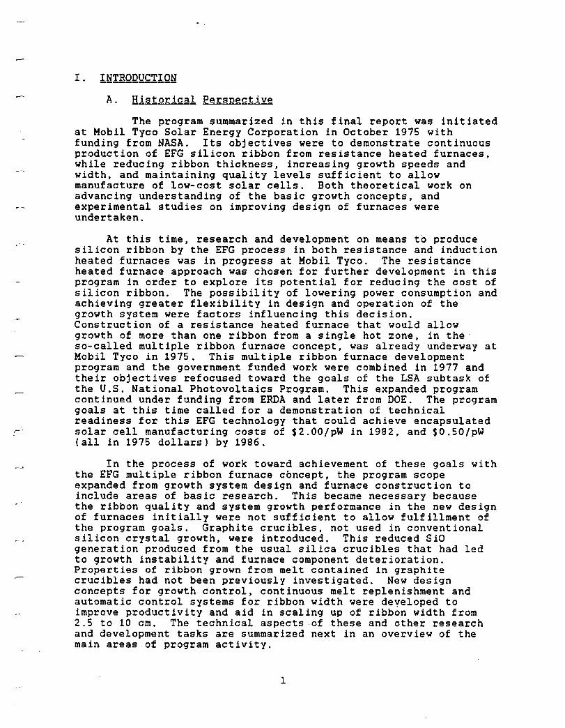
I. IHIBQQUCIIQH A. Historical Perspe£tlY!
The program summarized in this final report was initiated at Mobil Tyco Solar Energy Corporation in October 1975 with funding from NASA. Its objectives were to demonstrate continuous production of EFG silicon ribbon from resistance heated furnaces, while reducing ribbon thickness, increasing growth speeds and width, and maintaining quality levels sufficient to allow manufacture of low-cost solar cells. Both theoretical work on advancing understanding of the basic growth concepts, and experimental studies on improving design of furnaces were undertaken.
At this time, research and development on means to produce silicon ribbon by the EFG process in both resistance and induction heated furnaces was in progress at Mobil Tyco. The resistance heated furnace approach was chosen for further development in this program in order to explore its potential for reducing the cost of silicon ribbon. The possibility of lowering power consumption and achieving greater flexibility in design and operation of the growth system were factors influencing this decision. Construction of a resistance heated furnace that would allow growth of more than one ribbon from a single hot zone, in the· so-called multiple ribbon furnace concept, was already underway at Mobil Tyco in 1975. This multiple ribbon furnace development program and the government funded work were combined in 1977 and their objectives refocused toward the goals of the LSA subtask of the U.S. National Photovoltaics Program. This expanded program continued under funding from ERDA and later from DOE. The program goals at this time called for a demonstration of technical readiness for this EFG technology that could achieve encapsulated solar cell manufacturing costs of $2.00/pW in 1982, and $0.50/pW (all in 1975 dollars) by 1986.
In the process of work toward achievement of these goals with the EFG multiple ribbon furnace concept, the program scope expanded from growth system design and furnace construction to include areas of basic research. This became necessary because the ribbon quality and system growth performance in the new design of furnaces initially were not sufficient to allow fulfillment of the program goals. Graphite crucibles, not used in conventional silicon crystal growth, were introduced. This reduced SiO generation produced from the usual silica crucibles that had led to growth instability and furnace component deterioration. Properties of ribbon grown from melt contained in graphite crucibles had not been previously investigated. New design concepts for growth control, continuous melt replenishment and automatic control systems for ribbon width were developed to improve productivity and aid in scaling up of ribbon width from 2.5 to 10 cm. The technical aspects of these and other research and development tasks are summarized next in an overview of the main areas of program activity.
1
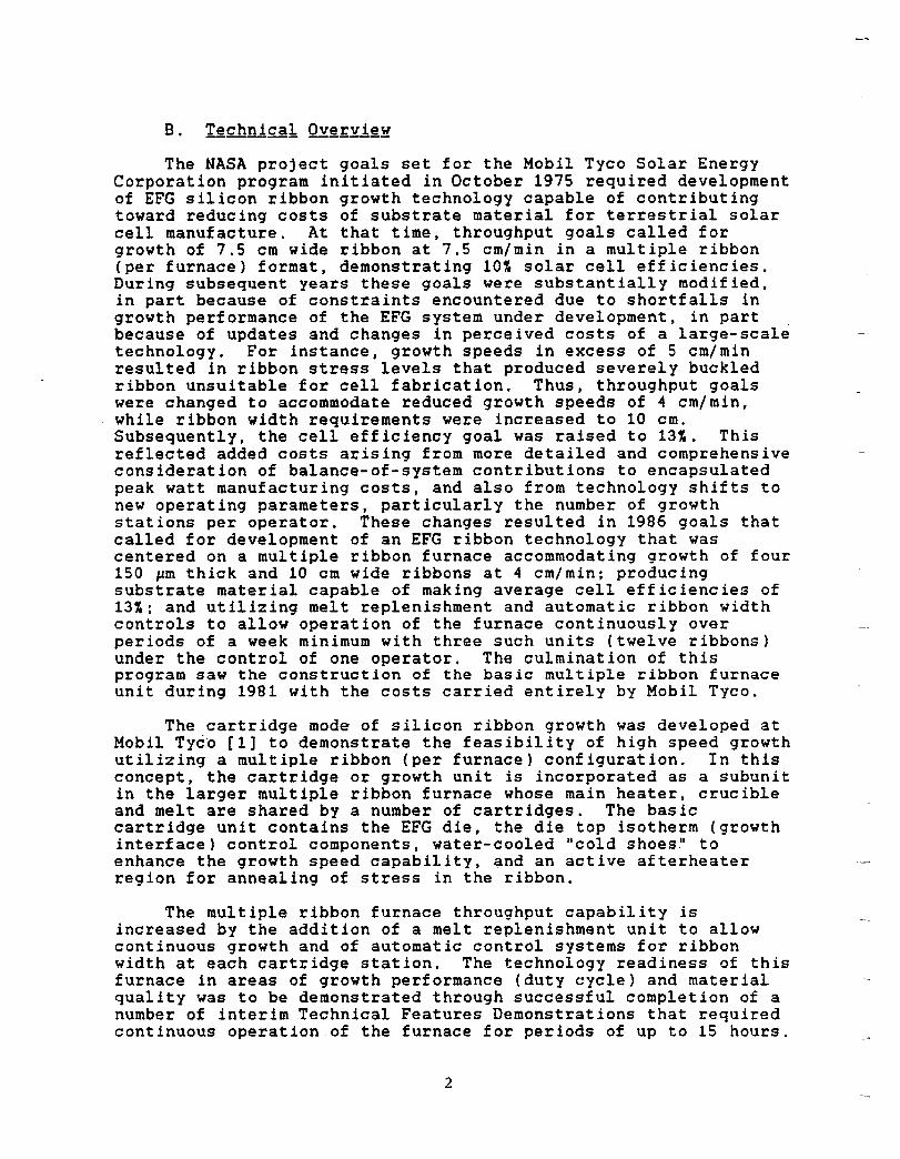
The NASA project goals set for the Mobil Tyco Solar Energy Corporation program initiated in October 1975 required development of EFG silicon ribbon growth technology capable of contributing toward reducing costs of substrate material for terrestrial solar cell manufacture. At that time, throughput goals called for growth of 7.S cm wide ribbon at 7.S cm/min in a multiple ribbon (per furnace) format, demonstrating 10~ solar cell efficiencies. During subsequent years these goals were substantially modified, in part because of constraints encountered due to shortfalls in growth performance of the EFG system under development, in part because of updates and changes in perceived costs of a large-scale technology. For instance, growth speeds in excess of 5 cm/min resulted in ribbon stress levels that produced severely buckled ribbon unsuitable for cell fabrication. Thus, throughput goals were changed to accommodate reduced growth speeds of 4 cm/min, while ribbon width requirements were increased to 10 cm. Subsequently, the cell efficiency goal was raised to 13~. This reflected added costs arising from more detailed and comprehensive consideration of balance-of-system contributions to encapsulated peak watt manufacturing costs, and also from technology shifts to new operating parameters, particularly the number of growth stations per operator. These changes resulted in 1986 goals that called for development of an EFG ribbon technology that was centered on a multiple ribbon furnace accommodating growth of four 150 ~m thick and 10 cm wide ribbons at 4 cm/min; producing substrate material capable of making average cell efficiencies of 13~; and utilizing melt replenishment and automatic ribbon width controls to allow operation of the furnace continuously over periods of a week minimum with three such units (twelve ribbons) under the control of one operator. The culmination of this program saw the construction of the basic multiple ribbon furnace unit during 1981 with the costs carried entirely by Mobil Tyco.
The cartridge mode of silicon ribbon growth was developed at Mobil Tycio [1] to demonstrate the feasibility of high speed growth utilizing a mUltiple ribbon (per furnace) configuration. In this concept, the cartridge or growth unit is incorporated as a subunit in the larger multiple ribbon furnace whose main heater, crucible and melt are shared by a number of cartridges. The basic cartridge unit contains the EFG die, the die top isotherm (growth interface) control components, water-cooled "cold shoes" to enhance the growth speed capability, and an active afterheater region for annealing of stress in the ribbon.
The multiple ribbon furnace throughput capability is increased by the addition of a melt replenishment unit to allow continuous growth and of automatic control systems for ribbon width at each cartridge station. The technology readiness of this furnace in areas of growth performance (duty cycle) and material quality was to be demonstrated through successful completion of a number of interim Technical Features Demonstrations that required continuous operation of the furnace for periods of up to 15 hours.
2
Development tasks for machine readiness that were addressed in working toward interim Technical Features Demonstrations involved design and testing of various pieces of equipment and concepts of growth. These were carried out using two single cartridge furnaces as well as the multiple ribbon furnace. The projects most relevant to contributing toward success of the program are summarized next.
(1) Design, construction and testing of resistance heated growth systems. These were introduced as an alternative to the conventional rf induction heating to increase efficiency and provide flexibility in attaining a high speed continuous ribbon growth capability [2]. A multiple ribbon furnace main zone configuration was developed using graphite resistance heaters for crucible and melt replenisher unit heating [3]. Resistance heaters were introduced to control die top isotherms (growth interface position) and ribbon edge location at individual cartridge ·stations [4].
(2) Scale-up of ribbon width from 2.5 to 10 cm. This was carried out in several stages. The initial Technical Features Demonstration (May 1979) goals were successfully achieved with multiple growth of five 5 cm wide ribbons (Section III, page 29 of this report). In concurrent studies, research on 7.5 cm wide ribbon growth (Section III, page 31 of this report) indicated that unacceptable stress levels and buckling developed at growth speeds of about 5 cm/min and above. The 10 cm cartridge system was subsequently introduced to allow reduction of the target growth speed to 4 cm/min (Section III, page 34 of this report), and optimizations of performance and ribbon thickness of 200 ~m were successfully completed.
(3) Introduction of graphite crucibles [3,5]. Generation of SiD from silicon melt reaction with fused silica crucibles used in conventional silicon crystal growth systems shortens furnace parts lifetime, and affects growth stability. Graphite crucible designs that avoid these problems and further have the potential for reuse to lower ultimate product costs were successfully tested in the multiple ribbon furnace format [6].
(4) Development of special die designs and heater configurations for die top isotherm control. These have been demonstrated to lead to improvements in growth stability [4] and in ribbon quality [7].
(5) Development of automatic control systems for ribbon width. This achievement was required for operation of the multiple ribbon furnace unit at high duty rates with only one operator for up to five ribbon stations. A special anamorphic optical system [8] was introduced to provide improved sensitivity for viewing and controlling the growth interface for this task (see also Section III, pages 32 and 46).
3
(6) Design and implementation of a melt replenishment for supplying silicon to the main furnace crucible [9,10]. has made it possible to demonstrate simultaneous continuous growth for periods of up to 15 hours in the multiple ribbon furnace mode.
system This ribbon
(7) Design, construction and testing of cold shoe elements for growth speed enhancement up to 7.5 cm/min [1]. The maximum speed capability was not realized in practice because of the onset of thermal buckling at about 5 cm/min which led to growth destabilization. The cold shoe design was subsequently evolved to improve growth performance at the target speed of 4 cm/min and thickness of 200 ~m for 10 cm wide ribbon [S,9,1~].
(8) Construction of cartridge configurations allowing ribbon stress to be reduced [10]. Although full understanding of stress generating mechanisms has not yet been achieved, theoretical guidance has led to construction of growth systems that produce 10 cm wide ribbon with a low resi2ual stress and buckling amplitude. As a result, large area (50 cm ) blanks have been fabricated into solar cells for the first time from 10 cm wide ribbon grown at 3.5 cm/min and above (see Section IV, page 63 of this report).
(9) Development of understanding of ribbon property responses to growth condition and cell processing variations peculiar to silicon grown from melt contained in graphite crucibles. Unexpected influences of ambient variations were discovered [8,11], and it was demonstrated that material properties were sensitive to the level of oxygen available during the growth process, either through the presence of quartz in contact with the melt or from ambient gases reactive with silicon melt introduced in the meniscus/growth interface region [12]. Alternative means to introduce the oxygen via ambient gases CO2 and CO were studied in detail. The understanding gained in thIs work contributed toward achieve~ent of cell efficiency goals of the program. Smal1
2area (-5 cm ) cells of 13+~ were achieved, and
large area () 50 cm ) efficiencies of 11 to 12~ also resulted (see Section IV, page 70 of this report) from optimization studies.
(10) Extension of theoretical concepts in areas of stress' analysiS [12], heat and mass transport modeling of growth interface phenomena [13] and growth stability and dynamic system response [5] have contributed to overall understanding of silicon ribbon EFG.
During the multiple ribbon furnace development period, milestones were achieved in subtasks of the program aimed at demonstrating the baseline capabilities of the cartridge system in single ribbon furnaces in many of the above areas. At the program conclusion, December 31, 1981, it remained to integrate all these individual elements into operation of a prototype unit for the simultaneous growth of four 10 em wide ribbons. This multiple ribbon furnace had undergone construction and testing in an internal program funded entirely by Mobil Tyco during 1981. The
4
,-
new furnace was built with an updated design in order to correct significant shortcomings of the original multiple ribbon furnace. The latter had been constructed in 1975 for multiple growth of 5 cm wide ribbon. Subsequent rework to accommodate 10 cm wide ribbon cartridges had left the original furnace inadequately configured to achieve the interim Technical Features Demonstration goals set for the program in 1980.
An economic model to analyze costs associated with large scale implementation of the multiple ribbon furnace EFG technology was developed concurrently with the technical program (see Ref. [5], Section II, page 9, and Section III, page 34 of this report). This analysis was subsequently broadened with the help of the SAMICS economic costs analysis procedure [14].
The following sections of this report present a review of the milestones achieved during the course of EFG technology development pursuant to the 1986 FSA project goals. The tasks were changed on numerous occasions during the more than six years of continuous funding of the program. This resulted in frequent redirection of the program research and development efforts in response, and has generated information that covers a diverse spectrum of topics related to EFG silicon ribbon growth. There will be no attempt made here to review all these areas. The most significant engineering and scientific results have been referenced above and in publications and patents listed in Appendix 7. This report presents a program overview by reproducing two in depth reviews of the technology at important junctures of the program, and reports on the status of the multiple ribbon furnace technology for 10 cm wide ribbon at the end of 1981.
In Section II that follows, operation of the earliest design of multiple ribbon furnace for five 5 em wide ribbons is described in a report given for an in depth review of the technology at the 16th Program Integration Meeting (PIM) at JPL in April 1978. After a successful multiple ribbon furnace demonstration fulfilling the technology readiness criteria for this furnace followed in May 1979, it was reconfigured for growth of 10 cm wide ribbon. Subsequent work to achieve multiple ribbon growth of 10 cm wide ribbon in this furnace and to demonstrate the technical readiness goals set for 1980 is discussed in Section III. This material was presented during a second in depth review at the 18th PIM in September 1980. In Section IV, progress in design and construction of a new multiple ribbon furnace for four 10 cm wide ribbons is described, and results given of concurrent research work carried out during 1981 in stress reduction and quality improvement tasks in single ribbon furnaces for 10 cm wide ribbon. The program status is summarized in Section V.
5

Intentionally Left Blank
II. 12~h ElM EEg§gNTAIlQ~ - April 1979 - F.V. Wald
TASK II - LARGE AP£A SILICON SHEET TASK
Mobil Tyco Solar Energy Corporation
EFG SILICON RIBBON
Status Report
It seems appropriate to preface this presentation with a short historical introduction. The EFG method was invented in 1965 when efforts were made to prepare alumina fibers for the reinforcement of metal matrices. This work was quickly extended into preparing a variety of shapes and also a variety of materials which appeared to have utility in shaped form. At Tyco, the "Saphikon" division was established to fabricate and market sapphire shapes for a variety of purposes. The most popular of these shapes were however discovered to be fairly simple ones such as tubes and ribbons. The tubes were found to be suitable competitors in the high pressure sodium arc lamp market which was then solely based on the translucent "Lucalox" ceramic. The process for this purpose was, therefore, licensed to Corning Glass Works, which intended to compete in this market using multiple EFG sapphire tubes for which they set up a production facility.
It was also recognized early that EFG ribbons would compete in the substrate market for silicon on sapphire devices with Czochralski grown, sliced, and polished sapphire boules, and the process was subsequently licensed to Kyoto Ceramic, RCA and Allied Chemical for this purpose.
It is quite obvious, then, that since the early 1970 's the process as such has been well recognized as an industrially suitable competitive process for fabricating sapphire shapes.
In June 1971, we started our first small exploratory effort under the sponsorship of the U.S. Navy on growing Si ribbon, and in December of that year we published a report documenting that it was indeed possible to grow single crystal EFG ribbon from graphite dies [lJ. Simultaneously, an in-house effort was started to demonstrate that this ribbon possessed properties which made it a suitable vehicle for the preparation of electronic devices in general and, somewhat later, for solar cells in particular. Starting in 1972/73, the Jet Propulsion Laboratory and the National Science Foundation sponsored further efforts with the aim of making such a ribbon an economic vehicle for the preparation of solar cells [2,3J.
.., J
In 1974, recognizing the potential of photovoltaics in terrestrial solar energy conversion as well as the potential of the EFG ribbon technology in this field, Mobil Oil Corporation committed itself to expend $30 million in order to develop the technique toward that end and Mobil Tyco Sol-ar Energy Corporation was formed as a vehicle to accomplish this task. This, at that time, was surely the most significant commitment of private funds toward the development of any technique for photovoltaic solar energy conversion, and I much suspect it is even yet one of the largest of such commitments. Therefore, our present JPL sponsored effort is only one part of a large integrated facility devoted to decreasing the cost of all steps in the silicon solar power supply sequence from crystal growth to cell making and array fabrication. Recently, our process has also been licensed to a Japanese consortium which considered it the major contender for economical silicon sheet fabrication. It is clear, therefore, that a variety of groups consider EFG a viable industrial technology for several areas, including silicon sheet growth towards terrestrial power generation.
During our NSF-RANN contract (April 1973 - February 1975 [2]), we developed our first somewhat detailed analysis on the economics of the EFG process as it applies to the preparation of silicon solar cells at a cost of 50~/watt. The results then achieved were summarized as follows;
" ... The EFG process seems eminently capable of being developed to a point where it can be used in the production of silicon solar cells for sale at less than $SOO/kw (peak). The development areas which must be addressed to attain the full potential of the technique include:
1. The growth of wider and thinner ribbon. 2. Multiple ribbon growth. 3. Melt replenishment during growth. 4. Automatic controls for growth. 5. Low-cost polycrystalline silicon. 6. Low-cost ribbon to cell processing techniques.
In addition, low-cost techniques for "panelizing" the cells must be developed, possibly using solar concentrators. Finally, there is a great deal of upside potential from increased efficiency cells, say, 1St instead of 10~."
Based on these guidelines, we started evolving concepts and machinery to meet these various goals with a particular emphasis on the first four since these were by and large the "EFG-specific" ones and we could not hope to get any help towards solving the problems inherent therein by any general progress towards low-cost silicon solar cells.
8
From that time on, then, concepts for our present multiple furnace evolved, and its operation, recently demonstrated in a five-ribbon run over a 12-hour day, provided us with the necessary inputs to carry out a detailed cost analysis based on the SAMICS-IPEG model.
To get a realistic price from these guidelines does indeed require some significant detail of knowledge about the process. For instance, the space requirements of the machines should be reasonably well known. One should also be able to clearly distinguish which parts of the machine will in fact last through the depreciation cycle assumed in IPEG and which will not, and thus what can be counted as equipment and what is material. Also realistic duty cycle projections are essential or the IPEG denominator may be significantly off. Operating a real model of the equipment we will in fact use, backed by parts tests from single ribbon machines which are run on a three-shift pilot production basis, has therefore enabled us to make a fairly detailed analysis of the process. Since most of you have heard the analysis described at the last PIM and have also probably had a chance to study it in our last quarterly report [4], I will only highlight those parts here which I feel are particularly s ignif icant .
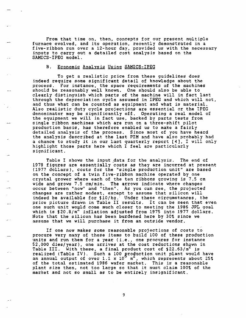
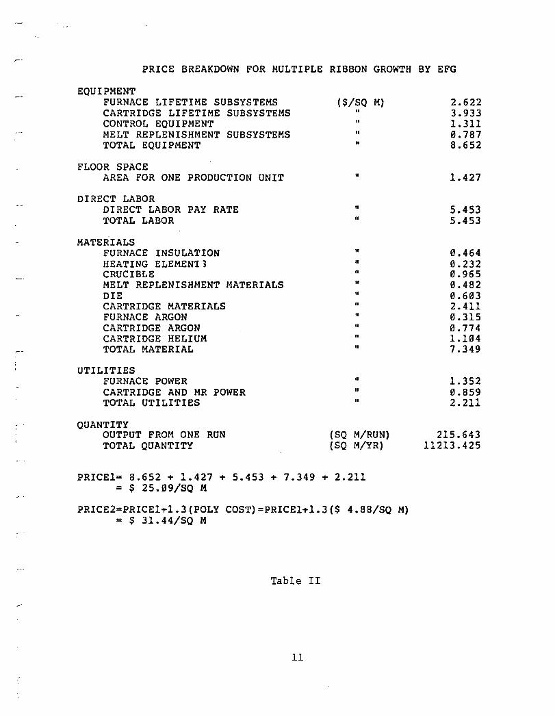
Table I shows the input .data f or the anal 1's is. The end of 1979 figures are essentially costs as they are incurred at present (1977 dollars), costs for the "single production unit" are based on the concept of a twin five-ribbon machine operated by one crystal grower where each of the ten ribbons growing is 7.5 cm wide and grows 7.5 cm/min. The arrows indicate where changes occur between "now" and "then". As you can see, the projected changes are rather modest, except to assume that silicon will indeed be availab.le for $10/ kg. - Under these circumstances, the price picture drawn in Table II results. It can be seen that even one such unit wo~ld come much closer to meeting the 1986 JPL goal which is $20.8/m~ inflation adjusted from 1975 into 1977 dollars. Note that the silicon has been burdened here by 30% since we assume that we will purchase it from an outside vendor.
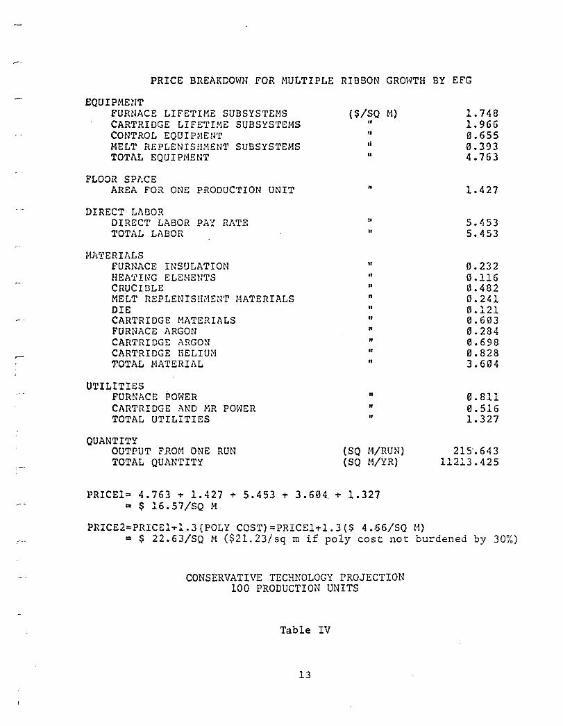
If one now makes some reasonable projections of costs to procure very many of these items to build 100 of these production units and run them for a year (i.e., one procures for instance 52,000 dies/year), one arrives at the cost reductions sh~wn in Table III. With these, a final product cost of $22.63/m is realized (Table IV). Such a 100 groquction unit plant would have an annual output of over 1.1 x 10 m, which represents about 25~ of the total estimated 1986 wafer market. This is a reasonable plant size then, not too large so that it must claim 100% of the market and not so small as to be entirely insignificant.
9
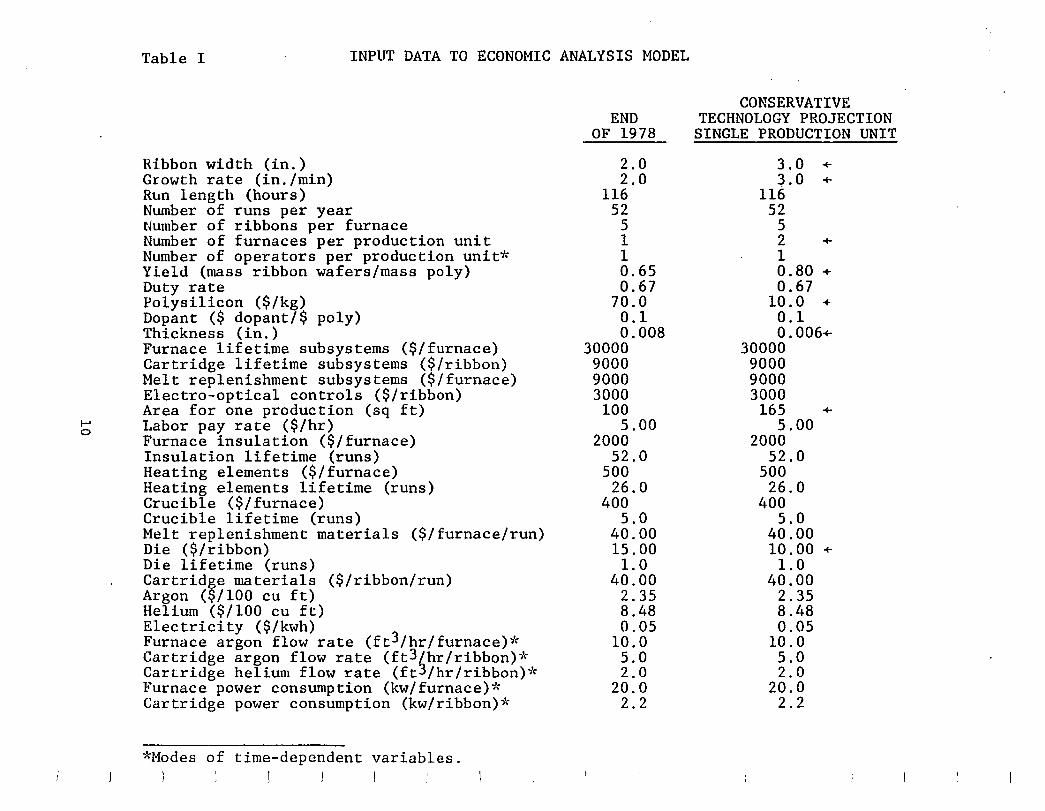
Table I INPUT DATA TO ECONOMIC ANALYSIS MODEL
Ribbon width (in.) Growth rate (in./min) Run length (hours) Number of runs per year Number of ribbons per furnace Number of furnaces per production unit Number of operators per production unit* Yield (mass ribbon wafers/mass poly) Duty rate Polysilicon ($/kg) Dopant ($ dopant/$ poly) Thickness (in.) Furnace lifetime subsystems ($/furnace) Cartridge lifetime subsystems ($/ribbon) Melt replenishment subsystems ($/furnace) Electro-optical controls ($/ribbon) Area for one production (sq ft) Labor pay rate ($/hr) Furnace insulation ($/furnace) Insulation lifetime (runs) Heating elements ($/furnace) Heating elements lifetime (runs) Crucible ($/furnace) Crucible lifetime (runs) Melt replenishment materials ($/furnace/run) Die ($/ribbon) Die lifetime (runs) Cartridge materials ($/ribbon/run) Argon (~/100 cu ft) Helium ($/100 cu ft) Electricity ($/kwh) Furnace argon flow rate (ft3/hr/furnace)* Cartridge argon flow rate (ft3/hr/ribbon)* Cartridge helium flow rate (ft3/hr/ribbon)* Furnace power consumption (kw/furnace)* Cartridge power consumption (kw/ribbon)*
*Modes of time-dependent variables. 1 J I
END OF 1978
2.0 2.0
116 52
5 1 1 0.65 0.67
70.0 0.1 0.008
30000 9000 9000 3000
100 5.00
2000 52.0
500 26.0
400 5.0
40.00 15.00 1.0
40.00 2.35 8.48 0.05
10.0 5.0 2.0
20.0 2.2
CONSERVATIVE TECHNOLOGY PROJECTION
SINGLE PRODUCTION UNIT
3.0 + 3.0 +
116 52
5 2 +
1 0.80 +
0.67 10.0 ..-0.1 0.006+
30000 9000 9000 3000
165 +
5.00 2000
52.0 500
26.0 400
5.0 40.00 10.00 + 1.0
40.00 2.35 8.48 0.05
10.0 5.0 2.0
20.0 2.2
PRICE BREAKDOWN FOR MULTIPLE RIBBON GROWTH BY EFG
EQUIPMENT FURNACE LIFETIME SUBSYSTEMS CARTRIDGE LIFETIME SUBSYSTEMS CONTROL EQUIPMENT MELT REPLENISHMENT SUBSYSTEMS TOTAL EQUIPMENT
FLOOR SPACE AREA FOR ONE PRODUCTION UNIT
DIRECT LABOR DIRECT LABOR PAY RATE TOTAL LABOR
MATERIALS FURNACE INSULATION HEATING ELEMENt, CRUCIBLE MELT REPLENISHMENT MATERIALS DIE CARTRIDGE MATERIALS FURNACE ARGON CARTRIDGE ARGON CARTRIDGE HELIUM TOTAL MATERIAL
UTILITIES FURNACE POWER CARTRIDGE AND MR POWER TOTAL UTILITIES
QUANTITY OUTPUT FROM ONE RUN TOTAL QUANTITY
($/SQ M) " " II
If
"
If
II
II
" n
" II
If
If
II
n
If
" II
"
(SQ M/RUN) (SQ M/YR)
PRICE1= 8.652 + 1.427 + 5.453 + 7.349 + 2.211 = $ 25.f19/SQ M
PRICE2=PRICE1+1.3(POLY COST)=PRICE1+1.3(S 4.88/SQ M) = S 31.44/SQ M
Table II
11
2.622 3.933 1.311 0.787 8.652
1.427
5.453 5.453
0.464 0.232 0.965 0.482 0.603 2.411 0.315 0.774 1.104 7.349
1.352 0.859 2.211
215.643 11213.425
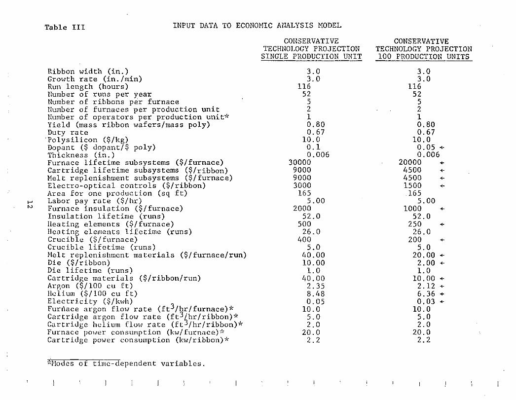
Table III INPUT DATA TO ECONOHIC AnALYSIS MODEL
Ribbon width (in.) Growth rate (in./min) Run length (hours) Number of runs per year Number of ribbons per furnace Number of furnaces per production unit Number of operators per production unit"': Yield (mass ribbon wafers/mass poly) Duty rate
'Po1ysilicon ($/kg) Dopant ($ dopant/$ poly) Thickness (in.) Furnace lifetime subsystems ($/furnace) Cartridge lifetime subsystems ($/ribbon) Melt replenishment subsystems ($/furnace) Electro-optical controls ($/ribbon) Area for one production (sq ft) Labor pay rate ($/hr) Furnace insulation ($/furnace) Insulation lifetime (runs) Heating elements ($/furnace) Heating elements lifetime (runs) Crucible ($/furnace) Crucible lifetime (runs) Helt replenishment materials ($/furnaee/run) Die ($/ribbon) Die lifetime (runs) Cartridge materials ($/ribbon/run) Arp,on (~/100 eu ft) Helium ($/100 cu ft) Electricity ($/kwh) Furrlace argon flow rate (ft3/hr/furnaee)* Cartridge argon flow rate (ft3 /hr/ribbon)* Cartridge helium flow rate (ft 3/hr/ribbon)* Furnace power consumption (kw/furnace):!'" Cartridge power consumption (kw/ribbon)~"
;';Nodcs of time-dependent variables.
CONSERVATIVE TECHNOLOGY PROJECTION
SINGLE PRODUCTION UNIT
3.0 3.0
116 52
5 2 1 0.80 0.67
10.0 0.1 0.006
30000 9000 9000 3000
165 5.00
2000 52.0
500 26.0
400 5.0
l~O. 00 10.00 1.0
llO.OO 2.35 8.48 0.05
10.0 5.0 2.0
20.0 2.2
CONSERVATIVE TECHNOLOGY PROJECTION 100 PRODUCTION UNITS
3.0 3.0
116 52
5 2 1 0.80 0.67
10.0 0.05 + 0.006
20000 +
4500 +
4500 +
1500 +
165 5.00
1000 +
52.0 250 +
26.0 200 +
5.0 20.00 +
2.00 +
1.0 10.00 +
2.12 + 6.36 +
0.03 +
10.0 5.0 2.0
20.0 2.2
PRICE BREAKDOWN FOR MULTIPLE RIBBON GROWTH BY EFG
EQUIPMENT FURNACE LIFETIME SUBSYSTEMS CARTRIDGE LIFETIME SUBSYSTEMS CONTROL EQUIPMENT MELT REPLENISHMENT SUBSYSTEMS TOTAL EQUIPHENT
FLOOR SP1:.CE AREA FOR ONE PRODUCTION UNIT
DIRECT LAI30R DIRECT LABOR PAY RATE TOTAL LABOR
HA'i'ERIALS FURNACE INSULATION HEATING ELEMENTS CRUCrOLE MELT REPLENISHMENT MATERIALS DIE: CARTRIDGE MATERIALS FURNACE ARGON CARTRIDGE ARGON CARTRIDGE HELIUM TOTAL HATERIAL
UTILITIES FURNACE POWER CARTRIDGE AND MR POWER TOTAL UTILITIES
QUANTITY OUTPUT FROM ONE RUN TOTAL QU.1\NTITY
(S/SQ H) .. .. Ii
"
"
" n
It
" •• n .. " n
It
" "
n
II
If
(SQ H/RUN) (SQ M/Y'R)
PRICE1= 4.763 ~ 1.427 T 5.453 T 3.604 T 1.327 I: $ 16.57/SQ 101
PRICE2=PRICE1~1.3(POLY COST)=PRICEITl.3($ 4.66/SQ M}
1.748 1.966 0.655 0.393 4.763
1.427
5.453 5.453
0.232 G.116 0.482 0.241 0.121 ".6g3 0.284 0.698 0.828 3.604
0.811 0.516 1.327
215-.643 11213.425
= $ 22.63/SQ 101 ($21.23/sq m if poly cost not burdened by 30%)
CONSERVATIVE TECHNOLOGY PROJECTION 100 PRODUCTION UNITS
Table IV
13
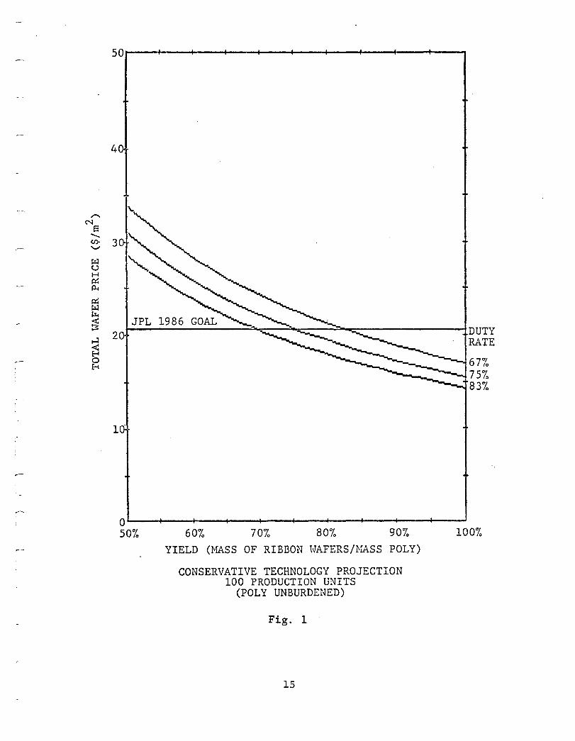
Based on these data, a variety of sensitivity analyses can now be performed and we have reported a number of them in our last quarterly report. For instance, it could be shown that multiple growth is always preferable to single growth, that argon cost and the cartridge cost are significant variables, and that, depending on the yield of material, provision of polysilicon at $10-$lS/kg is absolutely essential to achieving the price goal. However, in terms of discussing technology readiness, perhaps the most significant of the analyses is depicted in Fig. 1. It shows that there is a considerable range in the trade-offs between yield of material, and duty cycle for"a machine which clearly indicates that one is not rigidly tied to solving each and every small problem the technology may have. "
C. Status of Teghnolo9Y
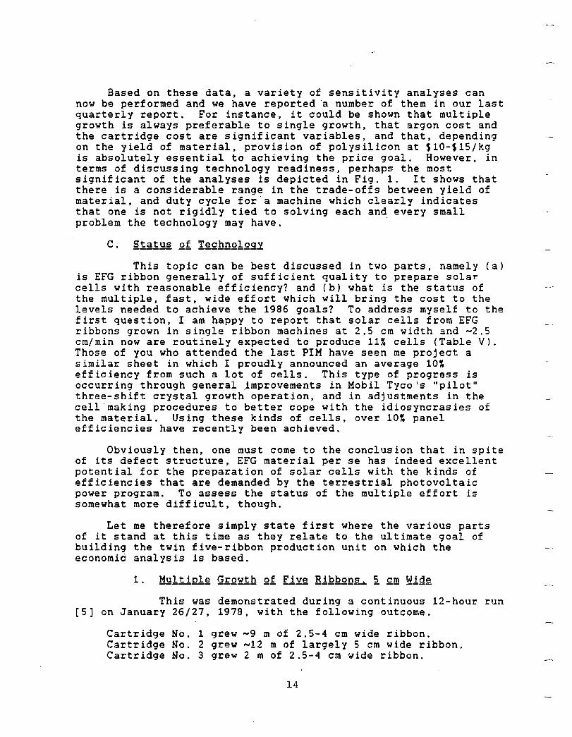
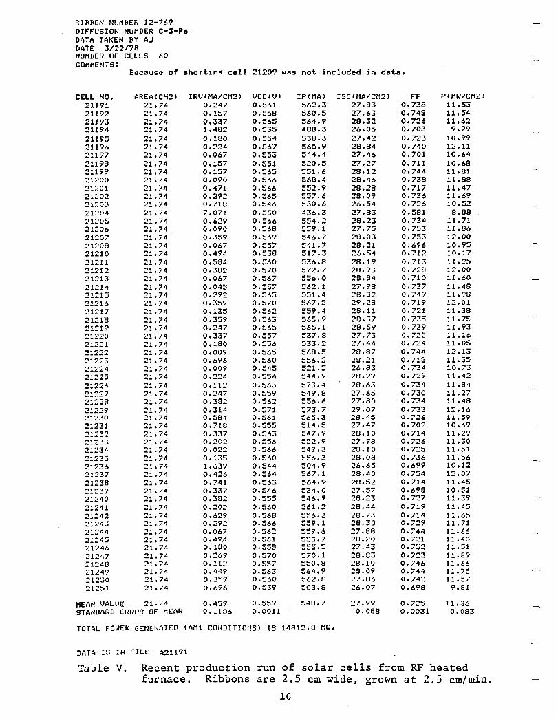
This topic can be best discussed in two parts, namely (a) is EFG ribbon generally of sufficient quality to prepare solar cells with reasonable efficiency? and (b) what is the status of the multiple, fast, wide effort which will bring the cost to the levels needed to achieve the 1986 goals? To address myself to the first question, I am happy to report that solar cells from EFG ribbons grown in single ribbon machines at 2.5 cm width and ~2.5 cm/min now are routinely expected to produce 11~ cells (Table V). Those of you who attended the last PIM have seen me project a similar sheet in which I proudly announced an average 10~ efficiency from such a lot of cells. This type of progress is occurring through general jmprovements in Mobil Tyco's "pilot" three-shift crystal growth operation, and in adjustments in the cell"making procedures to better cope with the idiosyncrasies of the material. Using these kinds of cells, over 10~ panel efficiencies have recently been achieved.
Obviously then, one must come to the conclusion that in spite of its defect structure, EFG material per se has indeed excellent potential for the preparation of solar cells with the kinds of efficiencies that are demanded by the terrestrial photovoltaic power program. To assess the status of the multiple effort is somewhat more difficult, though.
Let me therefore simply state first where the various parts of it stand at this time as they relate to the ultimate goal of building the twin five-ribbon production unit on which the economic analysis is based.
This was demonstrated during a continuous 12-hour run [5] on January 26/27, 1978, with the following outcome.
Cartridge No.1 grew -9 m of 2.S-4 cm wide ribbon. Cartridge No.2 grew -12 m of largely 5 cm wide ribbon. Cartridge No.3 grew 2 m of 2.5-4 cm wide ribbon.
14
"....
N S -<J>-'-'
~ C,) H p::: P-I
p::: ~ ~
~ ....:I
e:s 0 ~
50~--+---~---+--~~--+---~--~----~--~--~
4
3
DUTY 2 RATE
67% 75% 83%
1"
O~--+---~---+--~----~--~---+----~--~---J
50% 60% 70% 80% 90% 100% YIELD (MASS OF RIBBON HAFERS/NASS POLY)
CONSERVATIVE TECHNOLOGY PROJECTION 100 PRODUCTION UNITS
(POLY UNBURDENED)
Fig. 1
15
RI~BON NUMBER 1~-769 DIFFUSION NUMBER C-3-P6 DATA TAKEN BY AJ DATE 3122178 NUMBER OF CELLS 60 COMMENTS:
Because o~ shortin~ cell 21209 was not included in data.
CELL NO. 21191 21192 21193 21194 21195 21196 21197 21198 21199 21200 21201 21:!02 21203 21204 21205 21206 21:!07 21208 21210 21211 21212 21213 21214 21215 21216 21217 2121"8 21219 21220 21221 21222 21223 21224 21225 2122·'> 21227 21228 21229 21230 21231 ::!1232 21233 21:!34 21235 21236 21237 21238 21239 21240 21241 21242 21243 21244 21245 21246 21247 21248 21249 21250 21251
AREA(CM2) 21.74 21.74 21.74 21.74 21.74 21.74 21.74 21.74 21.74 21.74 21.74 21.74 21.74 21.74 21. 74 21.74 21.74 21.74 21.74 21.74 21.74 21.74 21.74 21.74 21.74 21.74 21.74 21.74 21.74 21.74 21.74 21.74 21.74 21.74 21.74 21.74 21.74 21. 74 21.74 21.74 21.74 21.74 21.74 21.74 21.74 21.74 21.74 21.74 21.74 21.74 21.74 21.74 21.74 21.74 21.74 21.74 21.74 21.74 :!1.74 21.74
MEAN VALUE 21.74 STANUARD ERROR OF MEAN
IRV(MAlCM2) 0.247 0.157 0.337 1.482 0.180 0.224 0.067 0.157 0.157 0.090 0.471 0.292 0.718 7.071 0.629 0.090 0.~59
0.067 0.494 0.584 0.382 0.067 0.045 0.292 0.3~9
0.135 0.359 0.247 0.337 0.180 0.009 0.696 0.009 0.224 0.112 ,0.247 0.382 0.314 0.584 0.718 0.337 0.202 0.022 0.135 1.639 0.426 0.741 0.337 0.382 0.202 0.629 0.292 0.067 0.49,4 0.100 0.2,,9 0.112 0.449 0.359 0.696
0.459 0.1106
VOC(V) 0.561 0.558 0.565 0.535 0.554 0.567 0.553 0.551 0.565 0.566 0.566 0.565 0.546 0.550 0.566 0.568 0.569 0.557 0.538 0.560 0.570 0.567 0.557 0.565 0.570 0.562 0.563 0.565 0.557 0.556 0.565 0.560 0.545 0.554 0.563 0.559 0.562 0.571 0.561 0.555 0.563 0.556 0.566 0.560 0.544 0.564 0.563 0.546 O.5Z5 0.560 0.568 0.566 0.562 0.561 0.559 0.570 O.5~7
0.563 0.560 0.539
0.559 0.0011
IP(MA> 562.3 560.5 564.9 488.3 538.3 565.9 544.4 520.5 551.6 568.4 552.9 557.6 530.6 436.3 554.2 559.1 546.7 541.7 517.3 536.8 572.7 556.0 562.1 551.4 567.5 559.4 565.9 565.1 537.8 533.2 568.5 556.2 521.5 544.9 573.4 549.8 556.6 573.7 ~65.3
514.5 547.9 552.9 549.3 556.3 504.9 567.1 564.9 534.0 546.9 561.2 556.3 559.1 559.6 553.7 rc-C' r .J...J...J • ..J
570.1 550.8 564.9 562.8 508.8
548.7
TOTAL POWER GEN~kATED (AMl CONDITIONS) IS 14812.8 MW.
DATA IS IN FILE A21191
ISC(HA/CH2) 27.83 27.63 28.32 26.05 27.42 28.84 27.46 27.27 2,8.12 28.46 28.28 28.09 26.54 27.83 28.23 27.75 28.03 28.21 26.54 28.19 28.93 28.84 27.98 28.32 29.28 28.11 28.37 28.59 27.73 27.44 28.87 28.21 26.83 28.29 28.63 27.65 27.80 29.07 28.45 27.47 28.10 27.98 28.10 28.08 26.65 28.40 28.52 27.57 28.23 28.44 28.73 28.38 27.88 28.20 27.43 28.83 28.10 28.09 27.86 26.07
27.99 0.088
FF 0.738 0.748 0.726 0.703 0.723 0.740 0.701 0.711 0.744 0.738 0.717 ' 0.736 0.726 0.581 0.734 0.753 0.753 0.696 0.712 0.713 0.728 0.710 0.737 0.749 0.719 0.721 0.735 0.739 0.722 0.724 0.744 0.718 0.734 0.729 0.734 0.730 0.734 0.733 0.7~6
0.702 0.714 0.726 0.725 0.736 0.699 0.754 0.714 0.698 0.727 0.719 0.714 0.729 0.744 0.721 0.7:;2 0.723 0.746 0.744 0.742 0.698
0.725 0.0031
P(HW/CM2) 11.53 11.54 11.62 9.79
10.99 12.11 10.64 10.68 11.81 11.88 11.47 11.69 10.52
8.88 11.71 11 .136 12.00 10.95 10.17 11.25 12.00 11.60 11.48 11.98 12.01 11.38 11.75 11.93 11.16 11.05 12.13 11.35 10.73 11.42 11.84 11.27 11.48 12016 11.59 10.69 11.29 11.30 11.51 11.56 10012 12.07 11.45 10.51 11.39 11.45 11.65 11.71 11.66 11.40 11.51 11.89 11.66 11.75 11.57 9.81
11.36 0.083
Table V. Recent production run of solar cells from RF heated furnace. Ribbons are 2.5 em wide, grown at 2.5 em/min.
16
Cartridge No.4 grew -13 m of largely 5 cm wide ribbon. Cartridge No.5 grew -9 m of largely 5 cm wide ribbon.
(The average growth speed for all cartridges was -3 cm/min.) Several problems were discovered here aside from the significant achievement that most of the many parts required worked quite reliably together for the 12-hour run. Cartridge No. 1 which is located next to the melt replenisher could never be brought up to full width; the thermal interaction between it and the melt replenisher made that impossible. In Cartridge No.3, a short circuit developed in the electrical system shortly after the run started, and we decided not to attempt to withdraw and repair it during this critical run.
Otherwise, the most general problem discovered was that we know too little about the phenomena which influence spreading of ribbons to full width. The spreading phase takes too long at present and requires the full attention of the operator. It is, however, a transient phase; as soon as the ribbon is spread to the "bulbous ends" of the die, it is anchored there. The phenomenon which then interferes with growth is the "freeze", a condition in which the liquid film collapses and the ribbon attaches to the die. If a "freeze" occurs, the ribbon must be "unfrozen" by increasing the die temperature and reseeding the ribbon and spreading it again. It is obvious then that frequent "freezes" in multiple growth are quite intolerable.
Towards the end of 1977, after several design changes had been made in the original cartridge, considerable improvements in the growth conditions were realized.
Nearly 2S m of ribbon were grown in eight of the runs. The width was up to 7.0 cm and speeds up to 6.3 cm/min were realized. The 7.5 cm belt puller has been routinely used in these experiments; in one run continuous growth of ribbon over a 1 3/4 hour period was achieved.
These experiments permitted important observations with respect to thermal stress in fast and wide ribbon growth. These problems include: (i) high residual stresses in the ribbon which shows up in problems of cutting it into solar. cell blanks, or (ii) generation of buckles in the ribbon during growth, which makes the ribbon useless for cell fabrication because it is not flat [4,5].
It was found that residual stress in the ribbon could be avoided by running the afterheater ) 1100 oC. However, there are still unsolved problems since it is difficult to keep the afterheater temperature this high if one has to use helium to cool the interface region. The helium then has a tendency to carry too much heat away from the afterheater. This will have to be solved by redesign of the cold shoe-heat shield-afterheater combination.
17
The most pressing problem at this time is the persistent presence of buckles in almost all ribbon. The reasons for this are not clear and the buckles have occasionally disappeared for no obvious reasons during a run. Under low speed growth conditions {( 4 cm/min) the ribbon is essentially always flat for widths > 2.5 cm in width, using present afterheater designs. -
Three significant pieces of information were derived here:
(a) Chemical analysis efforts on many ribbons have now fairly conclusively shown that the main culprit which influences the quality of ribbons grown from resistance heated machines is the stainless steel used in the construction of various hot parts [4]. A program to redesign these parts using other materials will now be undertaken.
(b) As a backup to these efforts, it has been demonstrated experimentally and theoretically that fluid flow effects in the ribbon strongly affect the impurity distribution. By using a center capillary only, to transport liquid to the top of the die, the impurity distribution in a "dirty" 5 cm wide ribbon was manipulated such that the center 2.5 cm width could be used to prepare solar cells of up to 10.6% efficiency [4]. These effects will now be vigorously explored to see whether their use is indeed practicable, i.e., can we concentrate impurities into the .very edge of the ribbon so that removal of the dirty part does not consume too much silicon.
(c) Ribbons grown at higher speeds () 4 cm/min) have shown a deterioration of the grain structure through the ribbon thickness. It was feared that this might negatively impact solar cell efficiency. It has now been rather conclusively demonstrated that this structure in itself is not the cause of any cell degradation [4] .
The "demonstration" phase of our current contract which ended on January 31, 1978, has thus functionally proven all the basic elements for multiple EFG growth at high speed (Table VI) and has uncovered no intrinsic physical limitations to prevent the achievement of the cost goals.
Having now identified all the basic elements, the normal next step would be to integrate them all into one true prototype machine. Before attempting to prepare such a design, however, there are three basic areas in which progress must· be made:
18
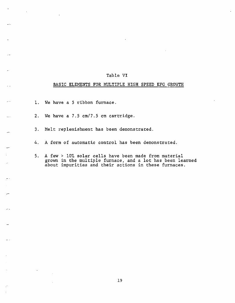
Table VI
BASIC ELEMENTS FOR MULTIPLE HIGH SPEED EFG GROWTH
1. We have a 5 ribbon furnace.
2. We have a 7.5 cm/7.S cm cartridge.
3. Melt replenishment has been demonstrated.
4. A form of automatic control has been demonstrated.
5. A few> 10% solar cells have been made from material grown in the multiple furnace, and a lot has been learned about impurities and their actions in these furnaces.
19
1. Select construction materials for the multiple furnace so that contamination is avoided and 10+~ cells result.
2. Produce an improved cartridge design that allows consistent stress-free growth of 7.S cm wide ribbon at 7.5 cm/min.
3. Improve growth stability by understanding, avoiding or automatically controlling "freezes".
This, in fact, is our basic program for 1978, in order of importance. If indeed at the end of this year either the multiple furnace or the single cartridge furnace produce 9-11~ cells fairly consistently, one may be quite confident that the quality goal can be achieved. This has to be done by judicious selection of the construction materials for the hot areas of these furnaces. As an example, currently the hot zone enclosure of this furnace is constructed using several square feet of stainless steel sheet. At present we are experimenting with both a molybdenum enclosure and a more rigid carbon insulation which is bakeable and needs no structural reinforcement. So far, scant attention has been paid to this kind of problem because a demonstration that the present concepts could indeed achieve the required volume output had to be provided first.
High speed wide ribbon growth at present is impeded by stress generation and "buckling". These problems are known to be related to the temperature gradients the ribbon sees on cooling and they can thus be addressed in principle by manipulation of these gradients.
This has to be, in practice. accomplished by a variety of design iterations in the thermal control parts of the growth cartridges [5].
Firstly, to achieve heat transfer of a sufficient magnitude to allow growth at 7.5 cm/min requires convectively aided radiative heat transfer, which is provided by arranging water-cooled heat removal elements which also contain channels for helium introduction within a fraction of a mm above the solid-liquid interface. Thus, -2 mm above the solid-liquid interface, the ribbon is cooled from its melting point - 1415 0 C to 1200 0 C in a very steep temperature gradient. However, below that temperature where Si is no longer able to relieve the thermal stresses (on the time scale of the growth) caused by contraction in a nonuniform gradient, the cooling must proceed in a uniform thermal gradient in order not to generate such stresses. To achieve this, linear cooling plates powered by an afterheater which operates at about 1100 0 C are provided, along with heat shields wnicn minimize thermal communication between the 1100 0 C operating temperature of the afterheater and the 500 to 600°C operatlng temperature of the heat removal element. Hence, the deslgn and the geometrical relationships of the heat removal
20
element-heat shield-afterheater combination determine the rate of growth which can be achieved along with the properties (stress/buckling) of the resulting ribbon which do, to a large extent. determine its utility for solar cell fabrication. The detail in the arrangement of parts a few millimeters above the die top is exceedingly important and must be arrived at largely by empirical methods. An important feature of the modular (cartridge) approach to growth system design is that these critical parts can be developed in small experimental furnaces and then transferred to the multiple machine where they will perform similarly. From the changes we are now making, we conclude that this is a tractable problem. Although progress in this area may not be very fast, we hope that during 1978 a sufficient number of gradient measurements and design iterations can be executed to arrive at a design for the production of straight, flat and reasonably stress-free ribbon (at 7.5 cm/min).
Finally. progress has to be made this year in understanding and controlling "freezes". They are a significant nuisance in multiple growth, and our electro-optical automatic width control system is completely defeated by their occurrence. To reiterate, a "freeze" is a condition where the liquid on the die top ceases to exist and thus the ribbon attaches to the die, which brings growth to a halt until it is restarted by the operator, which usually occasions loss of the full-width condition; thus respreading is required. Freezes have a long history in EFG growth and they are not a special feature of multiple or fast growth. However, in a situation where there is only one operator for ten ribbons, they are more detrimental since "unfreezing" and "reseeding" ribbons can consume a significant fraction of the operator's attention.
Although the phenomenon is well known. its origin is not. There is, however, a general correlation of the kind that the time between freezes has increased in our 2.5 cm pilot machines with time (the present record is set by a run where no freeze occurred for 28 hours), concurrent with improvements in operating procedure. accuracy of machine parts, placement of temperature control elements. and the like. Also, a large percentage of "freezes" is preceded by optical phenomena which are of sufficient magnitude and occur early enough so that a skilled operator can take corrective action. This indicates that an optical freeze sensing device with a suitable feedback control could probably be devised.
In any event, study of this problem has high priority in our 1978 program and we expect to have enough information on it to know of some ways to cope with it by the end of this year.
In summary, then, in the work during 1977 we clearly demonstrat2d t:hatfast. wide. and multiple growth of EFG ribbons is indeed possible using realistic engineering concepts. We also discovered some phenomena which, using present parts and machine
21
designs, interfere with stable multiple growth and high speed growth. These problems seem basically tractable ones, but they do require more delineation in order to devise the most effective solutions to them.
However at the present time there do not appear to be any outstanding tYng2m~nt2! problems which would seem to prevent multiple EFG growth from reaching the 1986 goals of the JPL program.
April 11, 1978 F.V. Wald, Program Manager
1. R. Stormont and F.V. Wald, "Silicon Ribbon", Final Report on Contract N00163-71-C-0711, December 1971.
2. B. Chalmers, A.I. Mlavsky, T. Surek, J.C. Swartz, R.O. Bell. D.N. Jewett, D.A. Yates, K.V. Ravi and F.V. Wald, "Continuous Silicon Solar Cells", Final Report NSF Grant No. GI-37067X (January 4, 1973 - February 28, 1975), issued August 1975.
3. H.E. Bates, D.N. Jewett, A.I. Mlavsky and V.E. White, "Thick Film Silicon Growth Techniques", Final Report on Contract NAS7-100, Subcontract JPL 953365, April 1975.
4. F.V. Wald et al., "Large Area Silicon Sheet by EFG" , Fourth Quarterly Report, JPL Subcontract No. 954355, January 15, 1978.
5. F.V. Wald et al., "Large Area Silicon Sheet by EFG", First Quarterly Report, JPL Subcontract No. 954355, April lS, 1978.
22
III. 1~1h ElM Ef~~gNIAIlQH - September 1980 - F.V. Wald
TASK II - LARGE AREA SILICON SHEET TASK
Mobil Tyco Solar Energy Corporation
EFG SILICON RIBBON
Status Report Contract Start Date: October 29, 1975
During the 9th PIM in April 1978, we presented a historical review of the EFG process and an update of our work to that time. The review also mentioned Mobil Oil Corporation's commitment of $30 million to this technology and the subsequent formation of Mobil Tyco Solar Energy Corporation. This commitment has made it possible to develop the technology to the point of product introduction, which is occurring now, and it is expected that this support for development will continue further into the future.
Already then, we had evolved the multiple machine design concepts which are still in use. Indeed, the power supply, furnace body, and some of the controls which were already installed then to test multiple 5 cm cartridge growth are the very same which are even now in use for the "Technical Features Demonstrations", in which three cartridges grow ribbon of 10 cm width. If nothing else then, this basic furnace structure, which was built in 1975, has proven quite durable, along with the "cartridge concept" for multiple EFG ribbon growth.
The conclusion presented during that presentation was that indeed the engineering concept chosen was feasible and could be developed so that it might meet the 1986 goals of the LSA program.
At that time, "growth stability" and "materials quality" were the main concerns expressed, and in the latter category we expected to have to work toward a 10~ (AM1) efficiency only. Although generally optimistic, the 1978 report sounded a number of cautionary notes, which, by hindsight, have proven to be all too true, and I quote:
"Hence, the design and the geometrical relationships of the heat removal element-heat shield-afterheater combination determine the rate of growth which can be achieved along with the properties (stress/buckling) of the resulting ribbon which do, to a large extent, determine its utility for solar cell fabrication. The detail in the arrangement of parts a few millimeters above the die top is exceedingly important and must be arrived at largely by empirical methods. An important feature of the modular (cartridge) approach to growth
23
system design is that these critical parts can be developed in small experimental furnaces and then transferred to the multiple machine where they will perform similarly. From the changes we are now making, we conclude that this is a tractable problem. Although pro9ress in this area may not be very fast, we hope that during 1978 a sufficient number of gradient measurements and design iterations can be executed to arrive at a design for the production of straight, flat and reasonably stress-free ribbon (at 7.5 cm/min) ...
... In summary, then, in the work during 1977 we clearly demonstrated that fast, wide, and multiple growth of EFG ribbons is indeed possible using realistic engineering concepts. We also discovered some phenomena which, using present parts and machine designs, interfere with stable multiple growth and high speed growth. These problems seem basically tractable ones, but they do require more delineation in order to devise the most effective solutions to them.
However at the present time there do not appear to be any outstanding ~Yndam~tal problems which would seem to prevent multiple EFG growth from reaching the 1986 goals of the JPL program."
The situation with respect to ribbon quality (in terms of solar cell efficiency) was still quite confused then, as only a few random cells from resistance-heated machines had achieved -101-(AM1) efficiency. although ribbon lots which were grown from induction-heated machines at low speeds were already fabricated into cells of 12+~ efficiency. The discrepancy between the ribbons grown from resistance-heated machines and induction-heated machines at that time was taken to be quite significant and was generally attributed to random impurities picked up from the construction materials of the resistance-heated equipment or was believed to be a fundamental feature of high speed growth.
1. Mul t.i121~ Gro~~h Dem~mstnt iQn - F i v~ B.iQQQn§~ §. Qm Wid~ g~ L§. QmLlnin
One of the major aims of the program during 1978/1979 then was a demonstration that the equipment existing at the time of the 9th PIM could indeed be considered to be prototypical for an eventual multiple ribbon production unit. This was to occur by demonstrating that the basic deSign was sufficiently sound to allow growth runs of at least one/day. using continuous melt replenishment. and a basic design that guaranteed a rudimentary level of purity. to be demonstrated by preparing cells of -91. efficiency.
24
From the early growth runs it was quite obvious that various improvements were necessary:
a. ~.Qng-Te~m ~~.Qwth Stab.ili.t.1l. In the beginning of 1978, the typical length of ribbon growth between "freezes" (i.e., a momentary collapse of the meniscus due to temperature fluctuations which freezes the ribbon to the die top, thus totally interrupting growth) in multiple-cartridge operation was less than two meters, corresponding to a time interval of not more than one hour. As the ribbons typically require between five and 15 minutes for initiation of stable growth, the probability that all five would be growing at any time was rather small. It thus became a job of the highest priority to increase the length of periods of stable, unattended growth.
A number of refinements were made to improve the performance of the pulling mechanisms and cartridge temperature control subsystems. However, the most dramatic effect upon stability was realized from a better control of the inert gas atmosphere around the growth meniscus. In the course of a general investigation of the flow rates and patterns of gases in the furnace, it was discovered that the destabilizing influence upon the meniscus of even small amounts of backstreaming air was severe. A s~parate inert gas purging supply within each cartridge was found to be necessary to prevent backstreaming under all conditions. These inert-gas supplies supplemented the argon purging system already present in the main furnace.
The above system design modifications were devised and verified in single-cartridge operation of the multiple-ribbon furnace. By the end of 1978, several such experimental runs had been made, in which growth was continuous for five to eight meters from first "seeding" until depletion of the melt. These long, stable growth periods were accomplished with only periodic, rather than continuous, operator surveillance. Such a schedule is necessary to allow the crystal growth operator to divide his attention among the five ribbons without strain. Throughout this period, a further factor which contributed significantly to more stable growth was the utilization of bulbous-ended dies.
b. 11m~~ment2.in ~~.th In.i.t.iat.i.Q!l.i.. Although the time needed by the operator to establish steady-state growth of a ribbon is highly dependent on the overall system stability, another important factor is whether or not the ribbon must be spread from some narrower width to the full width of the die. To eliminate this time-consuming procedure, a technique of full-width "seeding" was developed which included the addition of an electronic ramp circuit to coordinate the temperature drops of the die end and center regions during the starting transient. Following these improvements, the time required per cartridge for the first "seeding" of a run was reduced to less than five minutes, and start-ups after subsequent "freezes" took about one minute.
25
c. Machin~ Re112bi111Y~ A program of standardization of the cartridges and calibration of the related subsystems was carried out over the course of a year. These improvements permitted full advantage to be taken of the modular design of the overall system: Any cartridge, inserted into any position in the furnace, would respond similarly to operator inputs and would easily produce full-width ribbon. The success of this standardization effort is felt to be reflected in the tight distribution of the average efficiencies of solar cells made from ribbon grown from each of the five cartridges in the 1S-hour demonstration run (Table I). Finally, the cartridges have demonstrated the durability to last through several successive runs of 10 to 1S hours in length without replacement of any component except the dies, which are destroyed upon cool-down.
The redesign of the main furnace portion of the system, which was undertaken principally for material purity reasons, also resulted in a far more reliable unit than the original one. The new furnace has now operated for hundreds of hours without adjustments of parts replacement, and can thus be considered a prototype for future production units of this general type.
d. ContinuoY2 Me11 R~Rl~ni2hm~n1~ It was necessary to modify the apparatus for continuous feeding of liquid silicon utilized in early multiple-ribbon growth demonstrations in order to provide silicon at a sufficient rate for the higher material output made possible by the improvements discussed above. Refinements were also made to reduce the contamination of the melt by this unit, and a method was devised to continuously feed dopant to the silicon. This upgraded performance of the silicon feeding device unde21ies the capability of the overall system to produce about 90 cm of ribbon per minute, on a fully continuous basis. Of equal importance, material produced from replenished growth has performed as well, when made into solar cells, as non-replenished experimental ribbon grown under the same conditions.
e. Ribbon Qyal~~ Progress toward improvement of ribbon quality has proceeded along two general lines. First, a general clean-up of the multiple-ribbon system has been carried out to remove materials of construction with potential to contaminate the system with harmful impurities. This phase of the work has entailed a complete redesign of the main furnace as indicated above and modification of other parts to substitute for materials which are likely sources of contamination.
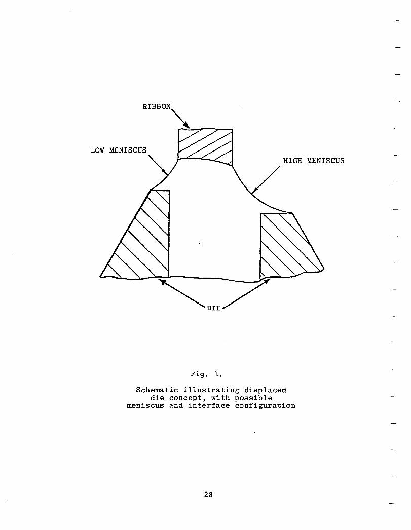
Also, the displaced die concept was introduced in an attempt to influence the interface shape through manipulation of the die-top temperature distribution across the ribbon thickness dimension. In responding to temperature changes, the interface shape further impacts the impurity distribution ahead of the growth interface and the morphology of the growing ribbon. A schematic illustrating the displaced die concept is shown in Fig. 1. In lowering, or "displacing", one die-top flat with respect to the other, as shown, the interface shape through the ribbon
26
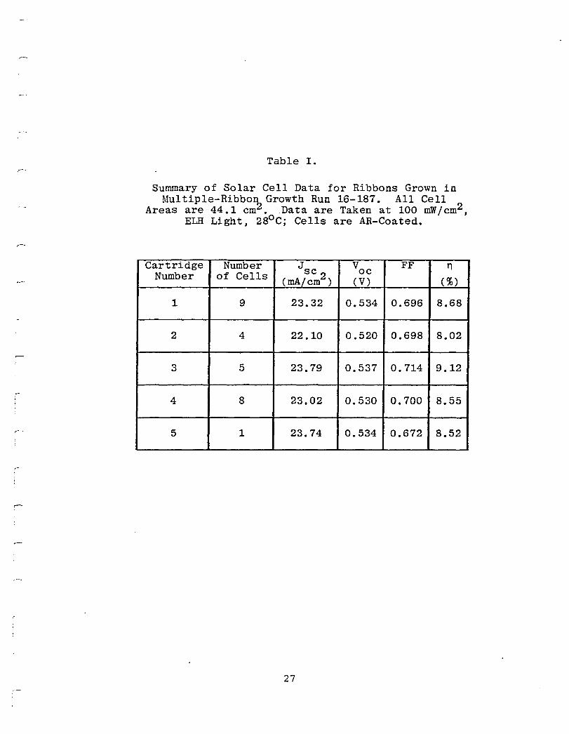
Table 1.
Summary of Solar Cell Data for Ribbons Grown in Multiple-Ribbo~Growth Run 16-187. All Cell
Areas are 44.1 em •. Data are Taken at 100 mW/em2 , ELH Light, 28o C; Cells are AR-Coated.
Cartridge Number J V FF n Number of Cells se oe
(mA/em2 ) (V) (%)
1 9 23.32 0.534 0.696 8.68
2 4 22.10 0.520 0.698 8.02
3 5 23.79 0.537 0.714 9.12
4 8 23.02 0.530 0.700 8.55
5 1 23.74 0.534 0.672 8.52
27
RIBBON~
..-::'-..,-..,-..-
LOW MENISCUS HIGH MENISCUS
Fig. 1.
Schematic illustrating displaced die concept, with possible
meniscus and interface configuration
28
~
I
thickness would tend to respond to die-top asymmetry because of imbalanced heat fluxes to the meniscus through the differing cross-sectional areas of the die top. In practice, this heat flux contribution is only one of several components making up the net interface heat balance. Other components arise from heat transfer between the meniscus, the ribbon, and their general environment, as well as from the latent heat of crystallization, and from heat transport by the melt.
Die displacement has been observed-to produce identifiable changes in the ribbon growth process. The most distinctive is a difference in the meniscus heights separating the two faces of the ribbon from the die top. This difference has further consequences in the manifestation of a striking asymmetry in ribbon surface properties. The ribbon face growing from above the displaced die-top (that with the higher meniscus) is virtually free of silicon carbide inclusions and smooth in appearance. The other ribbon face generally retains a normal complement of silicon carbide. This asymmetry has been used to advantage in solar cell fabrication by making cells using the SiC-free ribbon surface for the junction side. All cell parameters benefit from this approach. Further work is in progress to examine the relationship between die displacement and material properties in the search for an optimum displacement geometry.
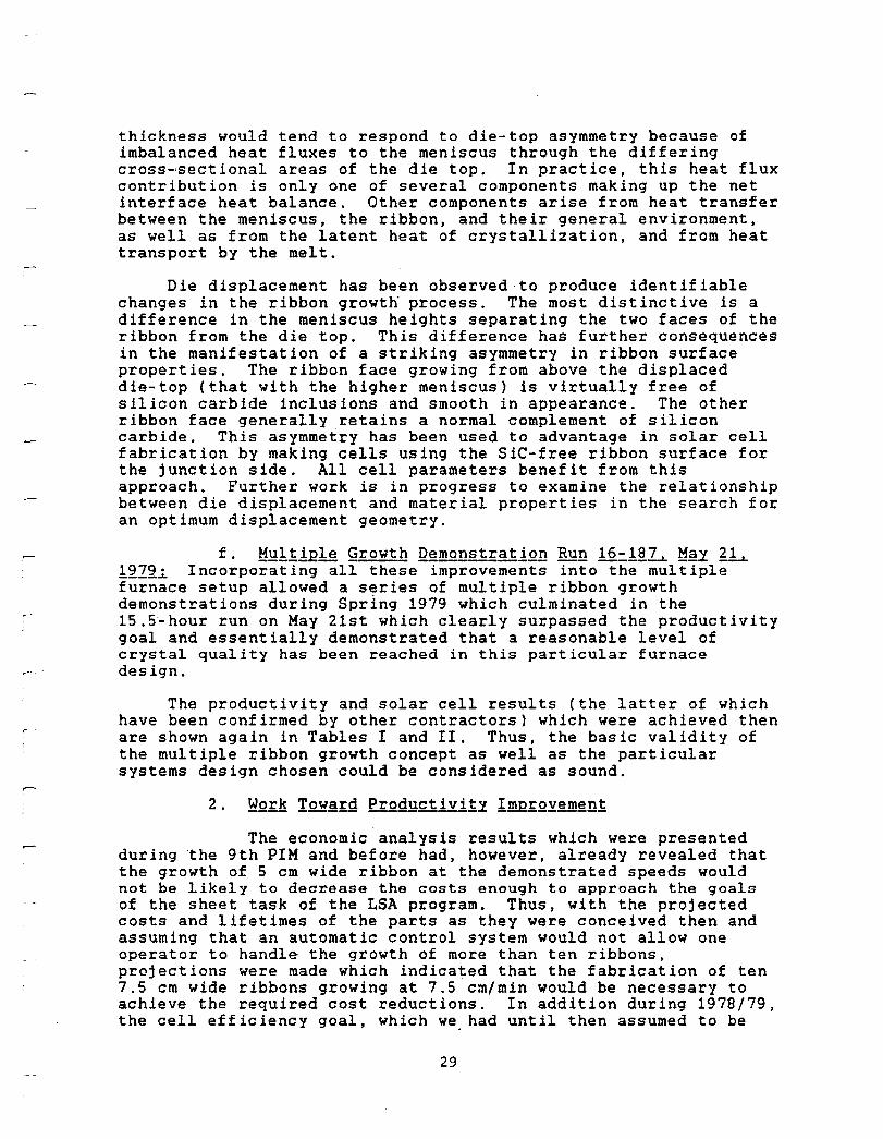
f. ~~111Bl~ gfgwth Q~~1f~11gD BYD 1~~1~~ ~~y 21~ 1212~ Incorporating all these improvements into the multiple furnace setup allowed a series of multiple ribbon growth demonstrations during Spring 1979 which culminated in the 15.~-hour run on May 21st which clearly surpassed the productivity goal and essentially demonstrated that a reasonable level of crystal quality has been reached in this particular furnace design.
The productivity and solar cell results (the latter of which have been confirmed by other contractors) which were achieved then are shown again in Tables I and II. Thus, the basic validity of the multiple ribbon growth concept as well as the particular systems design chosen could be considered as sound.
The economic analysis results which were presented during the 9th PIM and before had, however, already revealed that the growth of 5 cm wide ribbon at the demonstrated speeds would not be likely to decrease the costs enou9h to approach the 90als of the sheet task of the LSA program. Thus, with the projected costs and lifetimes of the parts as they were conceived then and assuming that an automatic control system would not allow one operator to handle the growth of more than ten ribbons, projections were made which indicated that the fabrication of ten 7.5 cm wide ribbons growing at 7.5 cm/min would be necessary to achieve the required cost reductions. In addition during 1979/79, the cell efficiency goal, which we had until then assumed to be
29
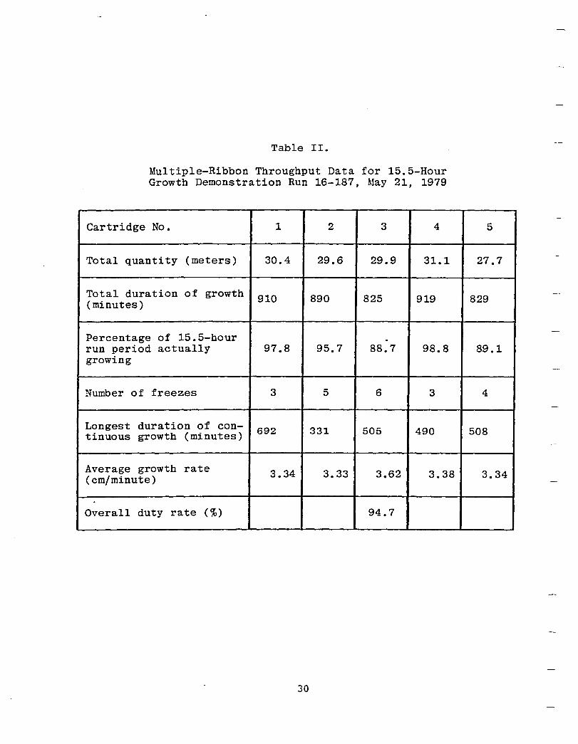
Table II.
Multiple-Ribbon Throughput Data for 15.5-Hour Growth Demonstration Run 16-187, May 21, 1979
Cartridge No. 1 2 3 4
Total quantity (meters) 30.4 29.6 29.9 31.1
Total duration of growth 910 890 825 919 (minutes)
Percentage of 15.5-hour . run period actually 97.8 95.7 88.7 98.8 growing
Number of freezes 3 5 6 3
Longest duration of con- 692 331 505 490 tinuous growth (minutes)
Average growth rate 3.34 3.33 3.62 3.38 (em/minute)
Overall duty rate (%) 94.7
30
5
27.7
829
89.1
4
508
3.34
r i ,
r I ,
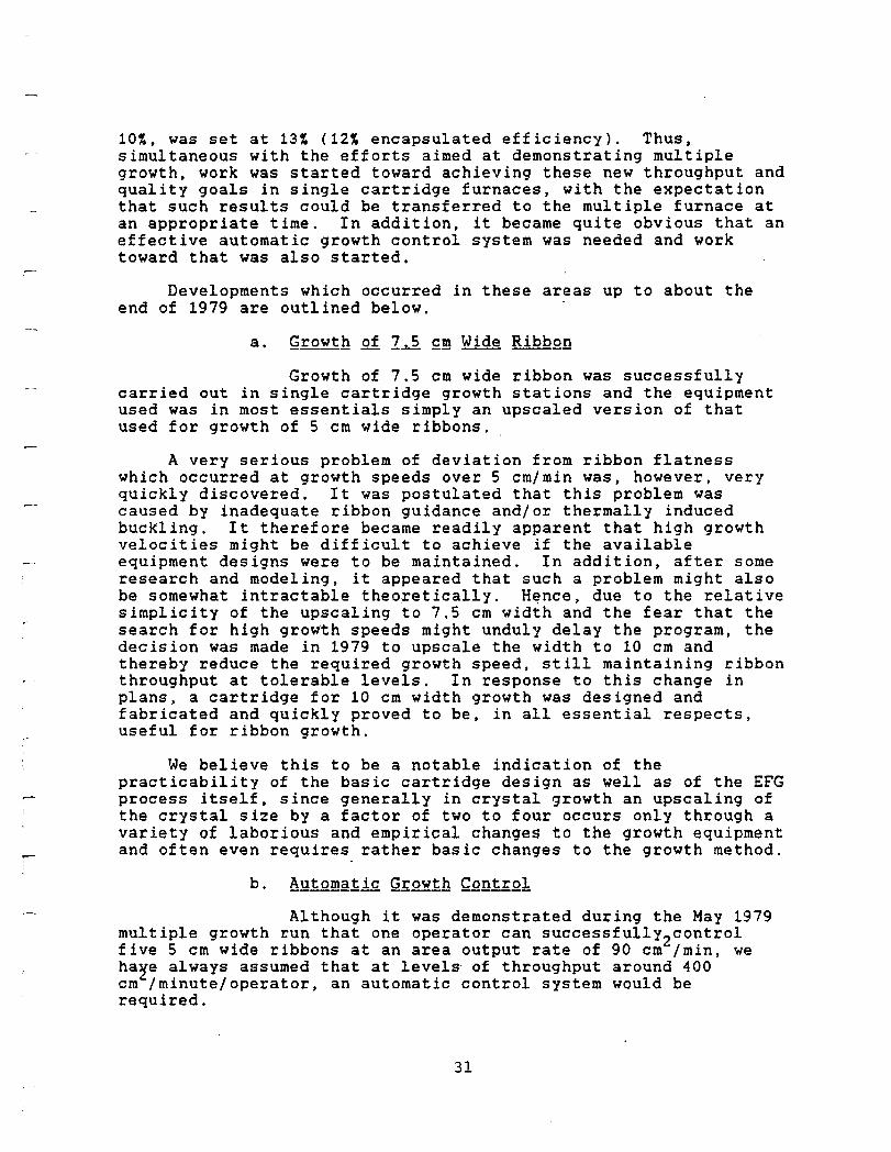
10~, was set at 13~ (12~ encapsulated efficiency). Thus. simultaneous with the efforts aimed at demonstrating multiple growth, work was started toward achieving these new throughput and quality goals in single cartridge furnaces, with the expectation that such results could be transferred to the multiple furnace at an appropriate time. In addition, it became quite obvious that an effective automatic growth control system was needed and work toward that was also started.
Developments which occurred in these areas up to about the end of 1979 are outlined below.
a. ~~~~h of 1.d £!!! Wide BibQ.Qn
Growth of 7.5 cm wide ribbon was successfully carried out in single cartridge growth stations and the equipment used was in most essentials simply an upscaled version of that used for growth of 5 cm wide ribbons.
A very serious problem of deviation from ribbon flatness which occurred at growth speeds over 5 cm/min was, however, very quickly discovered. It was postulated that this problem was caused by inadequate ribbon guidance and/or thermally induced buckling. It therefore became readily apparent that high growth velocities might be difficult to achieve if the available equipment designs were to be maintained. In addition, after some research and modeling, it appeared that such a problem might also be somewhat intractable theoretically. H~nce, due to the relative simplicity of the upscaling to 7.5 cm width and the fear that the search for high growth speeds might unduly delay the program, the decision was made in 1979 to upscale the width to 10 cm and thereby reduce the required growth speed, still maintaining ribbon throughput at tolerable levels. In response to this change in plans, a cartridge for 10 cm width growth was designed and fabricated and quickly proved to be, in all essential respects, useful for ribbon growth.
We believe this to be a notable indication of the practicability of the basic cartridge design as well as of the EFG process itself, since generally in crystal growth an upscaling of the crystal size by a factor of two to four occurs only through a variety of laborious and empirical changes to the growth equipment and often even requires rather basic changes to the growth method.
b. A'y~.Q!!!g~.1£ Gr.Q~~h Con~~.Q!
Although it was demonstrated during the May 1979 multiple growth run that one operator can successfullY2control five 5 cm wide ribbons at an area output rate of 90 cm /min, we ha~e always assumed that at level~ of throughput around 400 cm /minute/operator, an automatic control system would be required.
31
Up to that time, control of the growth process was essentially manual and achieved by adjustment of the temperature of cartridge components in the vicinity of the growth interface. A more advanced control system developed at Mobil Tyco optically monitors and automatically controls the interface position and ribbon width. This control system is designed to assist in steady-state growth only, leaving the task of starting growth and establishing control points to a human operator. A key element of the system is a TV camera fitted with an anamorphic optical system ~hich magnifies 20 times more in the vertical than in the horizontal direction. For purposes of electronic control of ribbon growth, the TV screen image is processed through a two-level quantizer and scan-segment integrators to produce signals which can be used to control heating elements and/or pulling speed.
The development of this system proceeded through 1979, and there is more discussion of it in a following section.
During 1978 and the beginning of 1979 the quality goal of the multiple ribbon growth program focused on question~. related to the uniformity of material over large areas (-50 cm ) and within long ribbons. This approach was in keeping with the emphasis in the program of demonstrating a capability for preparing greater than 10~ efficient solar cells from large area sheets grown at high throughput rates as the general potential of EFG ribbon had alrea2Y been demonstrated through the preparation of small area (-4 cm ) cells of efficiencies between 11~ and 14~ (AM1). Progress toward the efficiency goal for large area cells was steady, and aided by a better understanding of the factors contributing to material quality, as discussed in the paragraphs above.
Random sampling of ribbon grown in the five-cartridge demonstration and in a single-cartridge system for 7.5 cm wide ribbon has yielded large area cells with performance levels as given in Tables I and III. The spread in cell parameters over all five cartridges is notably narrow (Table I), and demonstrates that the multiple-ribbon growth station, in an operating mode representative of a production environment, is capable of producing large area cells of average efficiency of the order of 9~ (AM1). This performance level has been maintained in the course of scaling up the ribbon width to 7.5 cm (Table III).
The 7.5 cm wide ribbon was fabricated into 7.5 cm by 7.5 cm solar cells using a novel double bus bar configuration in order to achieve an optimized grid design. In subsequent testing of these cells for suitability in panel fabrication, it was realized that this grid geometry was not compatible with simple interconnect schemes. A return to a single bus bar grid configuration was therefore deemed desirable, particularly in the course of a further scaleup of ribbon width from 7.5 cm to 10 cm. The same
32
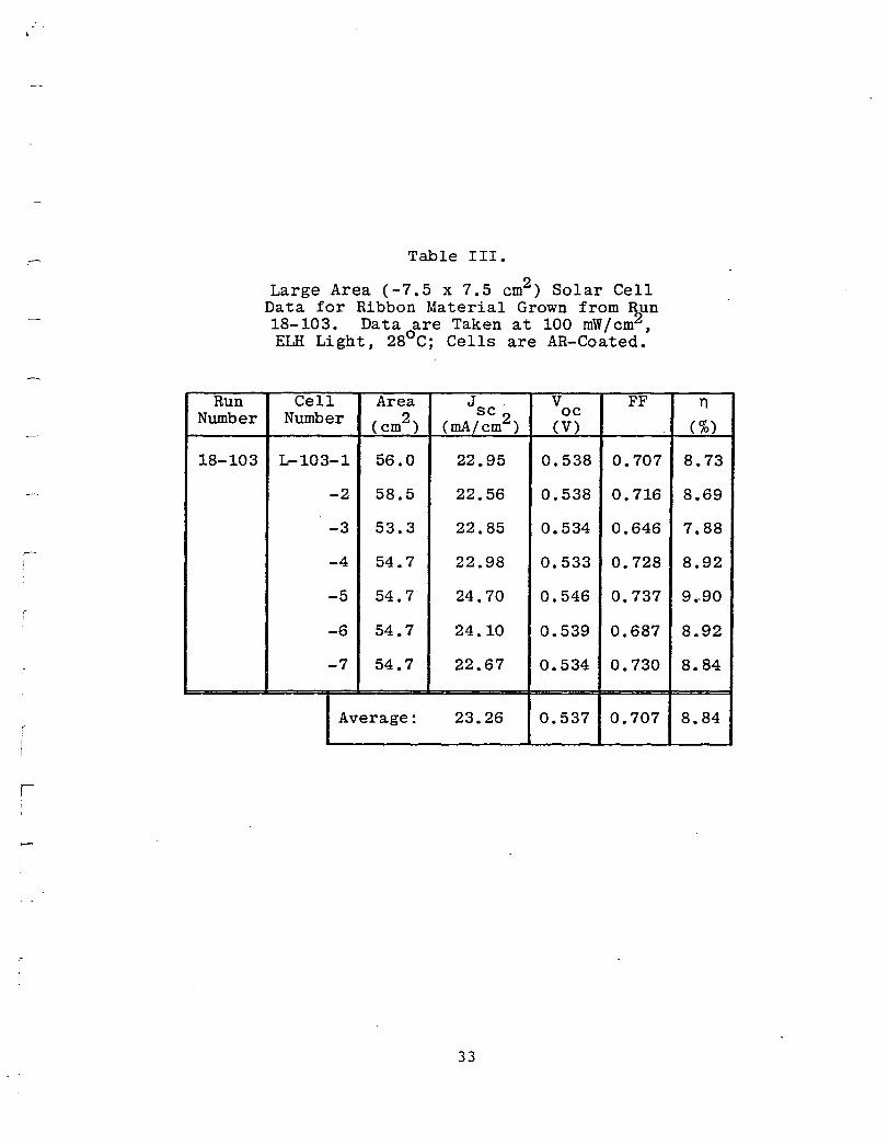
Run Number
18-103
r
Table III.
Large Area (-7.5 x 7.5 em2 ) Solar Cell Data for Ribbon Material Grown from Run 18-103. Data are Taken at 100 mW/em2 , ELH Light, 28o C; Cells are AR-Coated.
Cell Area J V FF Number 2 se oe
(em) (mA/em2 ) (V)
L-103-1 56.0 22.95 0.538 0.707
-2 58.5 22.56 0.538 0.716
-3 53.3 22.85 0.534 0.646
-4 54.7 22.98 0.533 0.728
-5 54.7 24.70 0.546 0.737
-6 54.7 24.10 0.539 0.687
-7 54.7 22.67 0.534 0.730
Average: 23.26 0.537 0.707
33
n (%)
8.73
8.69
7.88
8.92
9 •. 90
8.92
8.84
8.84
metallization mask is then made compatible with 5 cm by 10 cm ribbon blanks cut either from 5 cm wide ribbon or 10 cm wide ribbon, simply by reducing the length of ribbon cut along the growth direction from 10 cm to 5 cm, respectively.
Figure 2 shows the progress that has been made during the course of 1978 ~nd 1979 in increasing the efficiency of large area cells grown in a single-cartridge system for 5 cm and 7.5 cm wide ribbon growth. Early improvements (April to July, 1978) in efficiency have been associated with changes in cell processing and a switch from a distributed capillary (multi-capillary) die to one with a melt feed located central to the die (and ribbon). Other noticeable breaks occurred with the introduction of the displaced die (run 101) and after experimentation with the main zone purge rate (run 143), a topic that will be discussed further below. The understanding of factors which contribute to increased quality has then been applied to improve the quality of ribbon grown in the multiple-ribbon station.
Due to the change from a growth rate of 7.5 cm/min at 7.5 cm width to 10 cm wide ribbon grown around 4 cm/min, a new economic projection seemed required in order to ascertain whether these throughputs are still in accordance with the LSA project goals.
It can be clearly shown from Case 1 in Tables IV and V that this is indeed the case. Also, Case 2 in Tables IV and VI shows a "frozen" technology, which falls back on the growth of 5 cm wide ribbon. All the costs presented are in more or less "actual" 1980 dollars, i.e., based on equipment purchases and manufacturing costs experienced this year.
The most important singular goal of the program in 1980 was the full "Technical Features Demonstration" scheduled for July and defined as in Table VII.
In essence then, this demonstration would meet all the throughput parameters of a multiple furnace which are required to be met, so that the projected cost 90als can be reached. The efficiency goal was considered to be a modest one, achieved in principle through further refinements in the furnace construction and the crystal growth procedure.
In addition, the automatic controls system was to be developed to a point where its usefulness could be demonstrated by operating it on one cartridge during a multiple run. The three sections below then will trace the progress toward these sets of 90als during 1980.
34
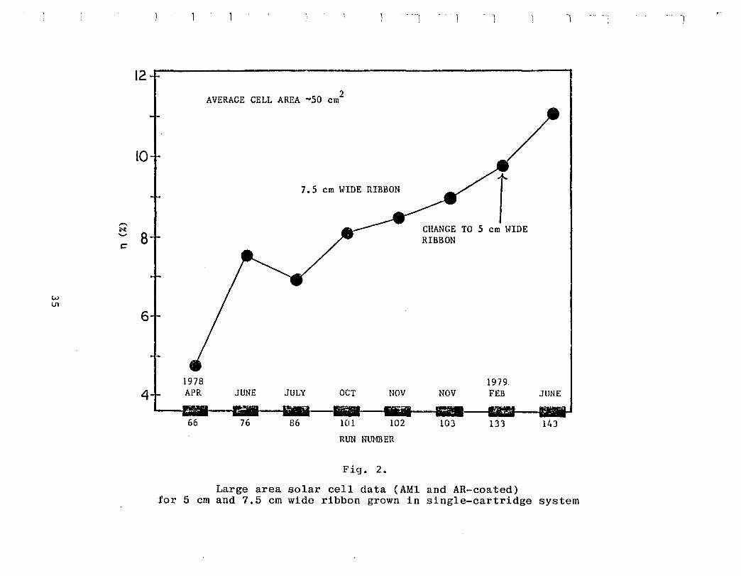
w U1
12
10
8
6
4
AVERAGE CELL AREA ~50 2 em
7.5 em WIDE RIBBON
1978 APR JUNE JULY OCT NOV
66 76 86 101 102
RUN NUMBER
Fig. 2.
Large area solar cell data (AMl for 5 em and 7.5 em wide ribbon grown in
CHANGE TO 5 em WIDE RIBBON
1979 NOV FEB
103 133
and AR-coated) single-cartridge
1
JUNE
143
system
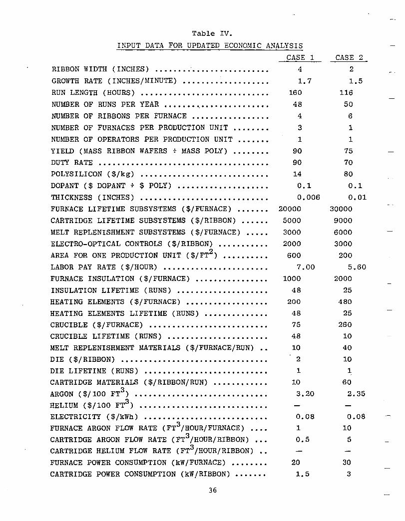
Table IV.
INPUT DATA FOR UPDATED ECONOMIC ANALYSIS
CASE 1
RIBBON WIDTH (INCHES) .•.•.••••.•...••.•••.••••
GROWTH RATE (INCHES/MINUTE) ••••••••••••..•..•.
RUN LENGTH ( HOURS) •••••.•••.•••..••••...•••.•.
NUMBER OF RUNS PER YEAR ••••••••.••••••••••••••• NUMBER OF RIBBONS PER FURNACE .••••••••••••••.• NUMBER OF FURNACES PER PRODUCTION UNIT •••••••• NU~rnER OF OPERATORS PER PRODUCTION UNIT .••••••
YIELD (MASS RIBBON WAFERS ~ MASS POLY) •••••••• DUTY' RATE ••••••••••••••••••••••••••.•••.••••••
POLYSILICON ($/kg) •••••••••••••••••••••••••.•• DOPANT ($ DOPANT ~ $ POLY) ••••••••••••••••••••
THICKNESS (INCHES) ••••••••.••••••••••••••••••• FURNACE LIFETIME SUBSYSTEMS ($/FURNACE) ••••••• CARTRIDGE LIFETIME SUBSYSTEMS ($/RIBBON) ••••••
MELT REPLENISHMENT SUBSYSTEMS ($/FURNACE) ••••• ELECTRO-OPTICAL CONTROLS ($/RIBBON) •••••••••••
2 AREA FOR ONE PRODUCTION UNIT ($/FT ) •••••••••• LABOR PAY RATE ($/HOUR) •••••.•..••••••••••.••• FURNACE INSULATION ($/FURNACE) •.•••.•••••••••• INSULATION LIFETIME (RUNS) ••••.••••••••••••••• HEATING ELEMENTS ($/FURNACE) •••••••••••••••••• HEATING ELEMENTS LIFETIME (RUNS) •••••••••••••• CRUCIBLE ($/FURNACE) ••••••••.••••••••••••••••• CRUCIBLE LIFETIME (RUNS) •••••••.•••••••••••••• MELT REPLENISHMENT MATERIALS ($/FURNACE/RUN) •• DIE ($/RIBBON) •••••••••••••••••.•.••••••••••••
DIE LIFETIME (RUNS) ••••••••••••••••••••••••••• CARTRIDGE MATERIALS ($/RIBBON/RUN) ••••••••••••
3 ARGON ($/100 FT ) ••••••••••••••••••••••••••••• 3 HELIUM ($/100 FT ) ••••••••••••••••••••••••••••
ELECTRICITY' ($ /kWh) ••••••••••••••••••••••••••• FURNACE ARGON FLOW RATE (FT3/HOUR/FURNACE) •••• CARTRIDGE ARGON FLOW RATE (FT3/HOUR/RIBBON) ••• CARTRIDGE HELIUM FLOW RATE (FT3/HOUR/RIBBON) •• FURNACE POWER CONSUMPTION (kW/FURNACE) •••••••• CARTRIDGE POWER CONSUMPTION (kW/RIBBON) •••••••
36
4
1.7
160
48
4
3
1
90 90 14
0.1 0.006
20000 5000
3000 2000 600
7.00
1000 48
200
48
75
48
10 2
1
10 3.20
0.08 1
0.5
20
1.5
CASE 2 2
1.5
116 50
6
1
1
75
70
80
0.1 0.01
30000 9000
6000 3000
200 5.60
2000 25
480
25 260
10 40
10 1
60 2.35
0.08 10
5
30 3
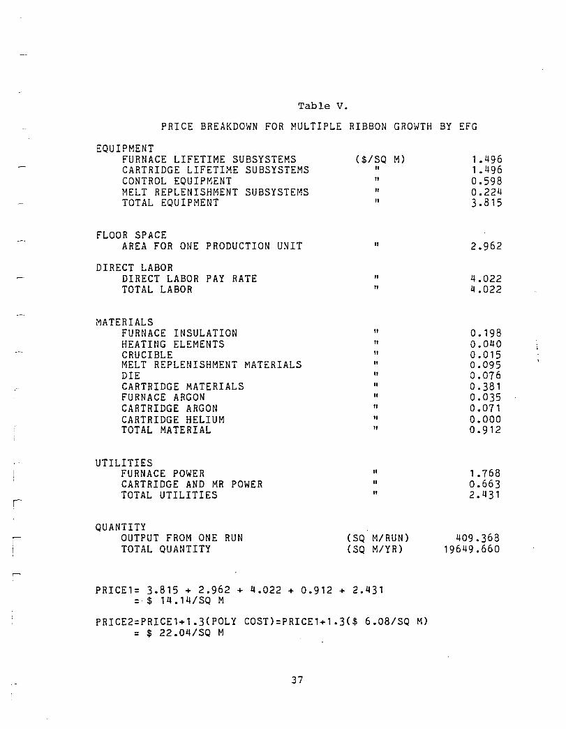
r
Table v.
PRICE BREAKDOWN FOR MULTIPLE RIBBON GROWTH BY EFG
EQUIPMENT FURNACE LIFETIME SUBSYSTEMS CARTRIDGE LIFETIME SUBSYSTEMS CONTROL EQUIPMENT MELT REPLENISHMENT SUBSYSTEMS TOTAL EQUIPMENT
FLOOR SPACE AREA FOR ONE PRODUCTION UNIT
DIRECT LABOR DIRECT LABOR PAY RATE TOTAL LABOR
MATERIALS FURNACE INSULATION HEATING ELEMENTS CRUCIBLE MELT REPLENISHMENT MATERIALS DIE CARTRIDGE MATERIALS FURNACE ARGON CARTRIDGE ARGON CARTRIDGE HELIUM TOTAL MATERIAL
UTILITIES FURNACE POWER CARTRIDGE AND MR POWER TOTAL UTILITIES
QUANTITY OUTPUT FROM ONE RUN TOTAL QUANTITY
($/SQ M)
" " " "
"
" "
" " " " " " " " " "
" " "
(SO M/RUN) (SQ M/YR)
PRICE1= 3.815 + 2.962 + 4.022 + 0.912 + 2.431 =. $ 1 4 • 1 4 I SO M
PRICE2=PRICE1+1.3(POLY COST)=PRICE1+1.3($ 6.08/S0 M) = $ 22.04/S0 M
37
1.496 1 .496 0.598 0.224 3.815
2.962
4.022 4.022
0.198 0.040 0.015 0.095 0.076 0.381 0.035 0.071 0.000 0.912
1.768 0.663 2.431
409.368 19649.660
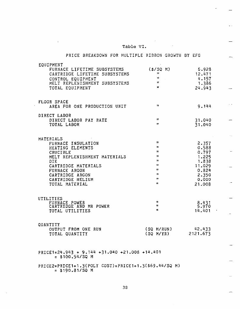
Table VI.
PRICE BREAKDOWN FOR MULTIPLE RIBBON GROWTH BY EFG
EQUIPMENT FURNACE LIFETIME SUBSYSTEMS CARTRIDGE LIFETIME SUBSYSTEMS CONTROL EQUIPMENT MELT REPLENISHMENT SUBSYSTEMS TOTAL EQUIPi1ENT
FLOOR SPACE AREA FOR ONE PRODUCTION UNIT
DIRECT LABOR DIRECT LABOR PAY RATE TOTAL LABOR
MATERIALS FURNACE INSULATION HEATING ELEMENTS CRUCIBLE MELT REPLENISHMENT MATERIALS DIE CARTRIDGE MATERIALS FURNACE ARGON CARTRIDGE ARGON CARTRIDGE HELIUM TOTAL MATERIAL
UTILITIES FURNACE POWER CARTRIDGE AND MR POWER TOTAL UTILITIES
QUANTITY OUTPUT FROM ONE RUN TOTAL QUANTITY
($/SQ M)
" " " "
"
" "
" " "
(SQ M/RUN) (SQ M/YR)
PRICE1=24.943 + 9.144 +31.040 +21.008 +14.401 = $100.54/SQ M
PRICE2=PRICE1+1.3(POLY COST)=PRICE1+1.3($69.44/SQ M) = '$ 1 9 0 • 8 1 I SQ M
38
6.928 12.471 4.157 1.386
24.943
9.144
31.040 31.040
2.357 0.588 0.797 1.225 1.838
11.029 0.824 2.350 0.000
21.008
8.431 5.970
14.401
42.433 2121.673
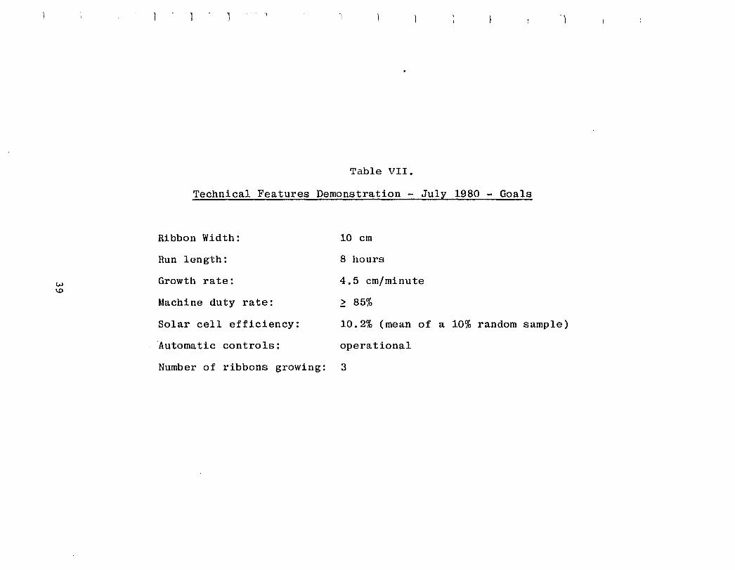
W 1.0
J --1 -1
Table VII.
Technical Features Demonstration - July 1980 - Goals
Ribbon Width: 10 cm
Run length: 8 hours
Growth rate: 4.5 em/minute
Machine duty rate: ~ 85%
Solar cell efficiency: 10.2% (mean of a 10% random sample)
Automatic controls: operational
Number of ribbons growing: 3
Also, a set of goals related to efficiency was, however, required inasmuch as 13+~ efficiency was to be demonstrated on a small cell and efficiency-limiting mechanisms were to receive continuing study.
1 . Work Toward the "Technical Features Demonstration" ---- ------ --- ---------- -------- --------------. During the first quarter of 1980, the operation of
Furnace 3A with three 10 cm growth stations was demonstrated for the first time. Performance of the individual growth stations was similar to that seen in single-ribbon runs made in this furnace in the fourth quarter of 1979, i.e., growth rates around 3.0 cm/min, and relatively poor stability (Table VIII). These characteristics yielded a machine duty rate far below that demonstrated in multiple (five 5 cm ribbon) operation of the furnace in May 1979. The low throughput demonstrated in these recent runs reflects both the increased stringency of design requirements for growth of the wider ribbon, and the smaller amount of developmental time invested in the 10 cm cartridge than the 5 cm system had undergone by the end of that phase of the contract.
Based on the outcome of these runs, a detailed plan was established for improvement of the cartridge and implementation of automatic growth controls to allow the final multiple growth demonstration goals to be met by the end of July 1980.
This plan included a number of measurements to characterize the cartridges as they operate in the multiple furnace, as detailed below, as well as simultaneous development of a cartridge in the single Furnace 17 and cross exchange of cartridges between Furnace 17 and the multiple Furnace 3A.
The baseline cartridge currently in use was subjected to a series of temperature, gas flow, and heat flow measurements to provide supporting data for the variety of developmental activities it was to undergo. Some examples of these measurements and the uses to which they may be put are:
• Temperatures of side walls, floor, face walls and die shield. Accurate determination of these temperatures is essential to the study of the die-top thermal environment. These measurements also permit a more precise determination to be made of relative locations and fits of these components at operating temperature. Finally, knowledge of temperatures in the cartridge help determine where reactive gases should be introduced, and help to predict the rates of their reaction with various components .
• Relationship between temperature distribution in the die and heating elemen~ power. These data are useful for determination of the gains·of closed-loop control systems, and choice of optimum heating element configuration.
40
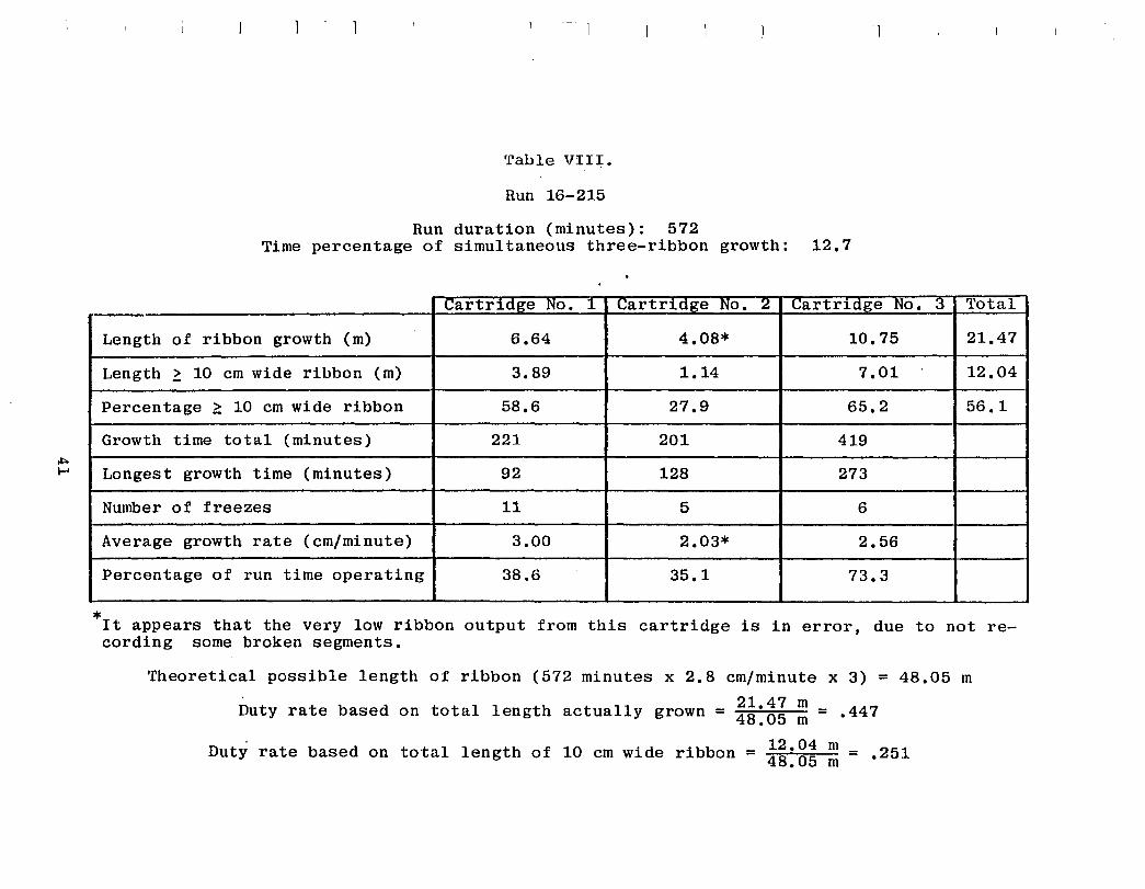
*
Table VIII.
Run 16-215
Run duration (minutes): 572 Time percentage of simultaneous three-ribbon growth: 12.7
Cartr1c1ge No. 1_ ~artr1c1Ke No. 2 ~artrldge No. 3 'l'otal
Length of ribbon growth (m) 6.64 4.08* 10.75 21.47
Length ~ 10 em wide ribbon (m) 3.89 1.14 7.01 12.04
Percentage ~ 10 em wide ribbon 58.6 27.9 65.2 56.1
Growth time total (minutes) 221 201 419
Longest growth time (minutes) 92 128 273
Number of freezes 11 5 6
Average growth rate (em/minute) 3.00 2.03* 2.56
Percentage of run time operating 38.6 35.1 73.3
It appears that the very low ribbon output from this cartridge is in error, due to not re-cording some broken segments.
Theoretical possible length of ribbon (572 minutes x 2.8 em/minute x 3) = 48.05 m
21.47 m Duty rate based on total length actually grown = 48.05 m = .447
Duty rate based on total length of 10 em wide ribbon = !~:g~ ~ = .251
• Temperature distribution in, and heat transfer to, the cold shoe. These measurements led to the design of an optimum cold shoe.
• Temperatures of heater feedbars. The molybdenum rods that feed current to the four heating elements in the cartridge are the components with the shortest life and may, in production operation, stand out as a major consumable-cost item. Design refinements must be considered for these bars, based on these measurements.
• Temperature profile experienced by ribbon in the linear cooling plates. These measurements help to clarify the causes of ribbon breakage.
• Flow characteristics of cartridge gas passages and orifices. Measurements of pressure drop vs. flow rate through the various cartridge gas passages are useful for controlling the composition and flow direction of gases in the cartridge, especially in the possible case of the deliberate introduction of oxygen-bearing gases to improve the ribbon's photovoltaic performance.
The establishment of routine growth of 10 cm ribbon in Furnace 17 provided some guidance for choice of the die heater configuration in the cartridges used in Furnace 3A, and has also raised questions about the effects of differences between the two furnaces on performance of the cartridges. The principal differences observed to data are in growth rate, thickness (related to rate), surface film formation,' and silicon carbide particle density. The faster growth (4.0 cm/min routinely) in Furnace 17 was of particular interest at that time, in light of the contract goals for multiple growth at 3.5 cm/min by the end of 1979 (not achieved) and 4.5 cm/min later in 1980. Two direct cartridge transfers were made in February 1980 between the two furnaces. In the first of these, the cartridge normally run in Furnace 17 was used in Furnace 3A in run 216, where it produced ribbon at an average of 2.95 cm/min, at a very low duty rate.
The second exchange of cartridges between the two furnaces produced more information. One of the Furnace 3A cartridges was outfitted with three extra thermocouples and was operated in the two furnaces on consecutive days. Furnace 3A was run with all three cartridges in place and powered (but two without dies installed) to simulate the thermal conditions of multiple operation. (This has been adopted as standard practice for developmental runs.) A range of growth rates from 2.5 to 3.5 cm/min was explored in Furnace 3A; above this upper limit, the die ends would freeze. Growth was stable at 3.'5 cm/min in Furnace 17, but the experiment ended before the rate could be raised further, when the afterheater thermocouple failed. This experiment
42
confirmed that ribbon can be pulled at a somewhat higher rate in Furnace 17 than 3A, using the same actual components. The three extra thermocouples present in the cartridge indicate the reason for this difference. Figure 3 shows the locations of these thermocouples in the general region of the die. The temperatures indicated during two stages of each run were as shown in Table IX. The temperatures in these locations are different in the two furnaces because of the different thicknesses and placement of the hot zone insulation, with Furnace 3A being the better insulated of the two. It is a basic principle of design of the multiple ribbon furnace that the thermal environment of the ribbon is determined primarily by the elements within the cartridge, and that growth performance is relatively insensitive to thermal fields external to the cartridge. This experiment reveals the degree to which growth performance (e.g., maximum pull rate) is sensitive to these external temperatures, mainly because the inner surfaces of the cartridge walls form part of the radiative environment of the growing ribbon. This sensitivity could be reduced by decreasing the vertical distance between the die top and cold shoe, subject to the constraint that the growth interface must be observed in order to control the process.
The temperature measurements shown for the cold shoes in Table IX are estimated to be 206 to 300 degrees higher than the actual temperatures due to the limited depth of the thermocouple cavity it is possible to make in these parts, and the extreme temperature difference between the cold shoes and their surroundings.
Part of the difference in typical growth rates of the same or similar cartridges operated in Furnaces 3A and 17 has to do with the tradeoff between rate and stability. Ribbon can consistently be grown in Furnace 17 close to the limiting rate because of full-time operator control, which is facilitated on that machine by the anamorphic video system.
c. ~QnQlusion~ frQm thg Mea~£~gment~ §ng frQm §ing!g ~~1;idgg g~~~imgn1§tion
The major conclusions arising from the work just described were that the most efficient shortcut to meet the "technical features" goals in a productivity sense would be to improve the efficiency of heat removal by the "cold shoes", in particular at the ends of the ribbon.
In addition, it was felt that immediate development of the automatic width control system would not only aid growth stability but also that this system could be used to quantitatively study various cold shoe/die/shield/heater combinations, and indeed these conclusions were proven out and a highly successful cold shoe design evolved after the automatic control system was made operational.
43
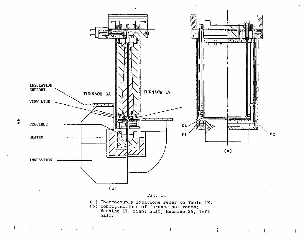
INSULATION SUPPORT
Vu."W LINE
..,. ..,. CRUCIBLE
HEATER
INSULATION
.~. .
FURNACE 3A FURNACE 17
------------D1
Fl
(b)
Fig. 3.
(a) Thermocouple locations refer to Table IX. (b) Configurations of furnace hot zones:
Machine 17, right half; Machine 3A, left half.
F2
( a)
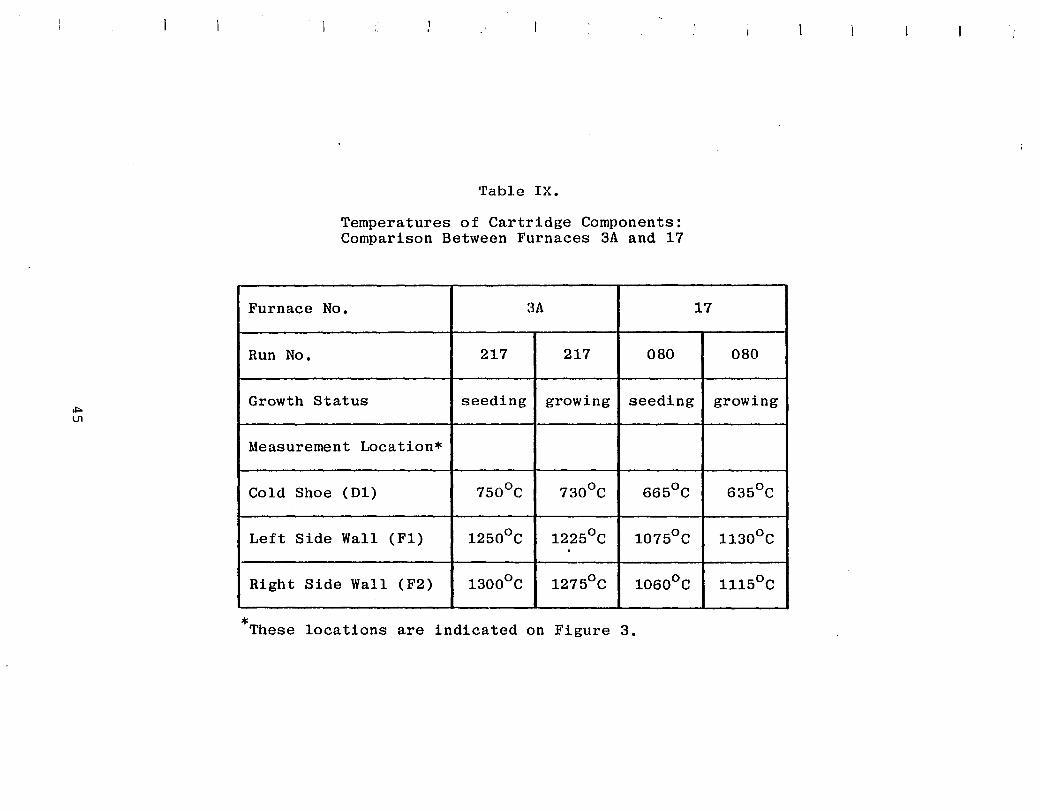
Table IX.
Temperatures of Cartridge Components: Comparison Between Furnaces 3A and 17
Furnace No. 3A 17
Run No. 217 217 080 080
Growth Status seeding growing seeding growing
Measurement Location*
Cold Shoe (D1) 750°C 730°C 665°C 635°C
Left Side Wall (F1) 12500 C 12250 C 10750 C 11300 C . Right Side Wall (F2) 13000 C 12750 C 10600 C 11150 C
* These locations are indicated on Figure 3.
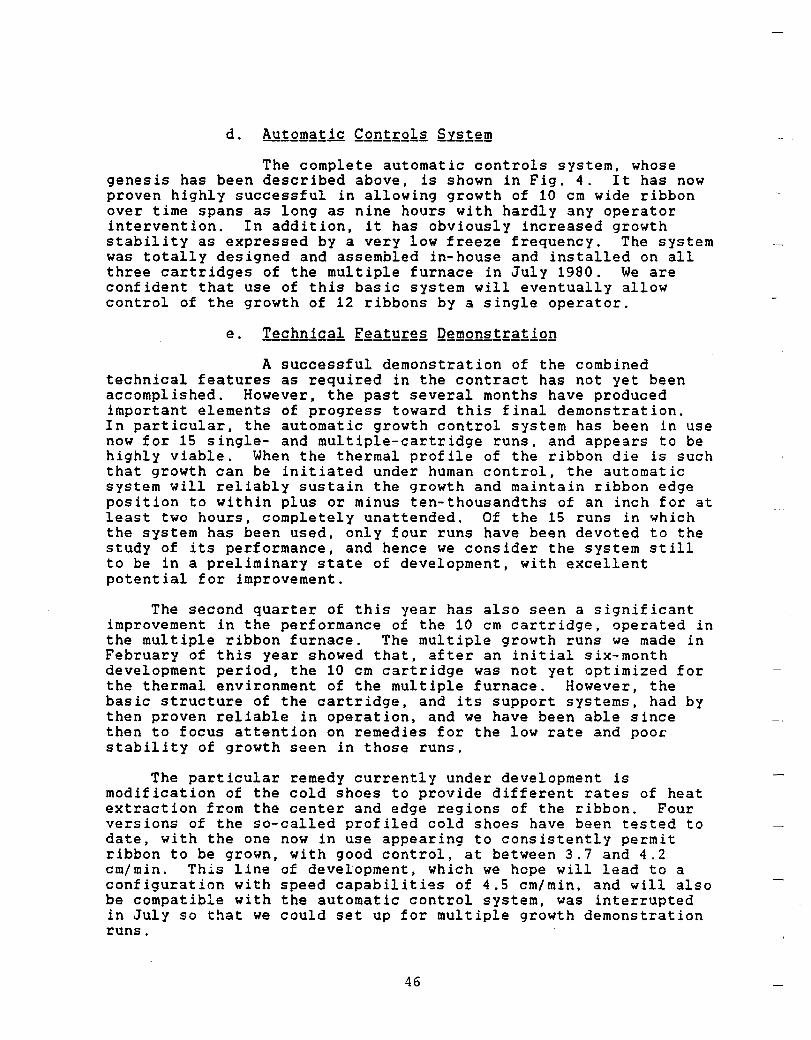
The complete automatic controls system, whose genesis has been described above, is shown in Fig. 4. It has now proven highly successful in allowing growth of 10 cm wide ribbon over time spans as long as nine hours with hardly any operator intervention. In addition. it has obviously increased growth stability as expressed by a very low freeze frequency. The system was totally designed and assembled in-house and installed on all three cartridges of the multiple furnace in July 1980. We are confident that use of this basic system will eventually allow control of the growth of 12 ribbons by a single operator.
A successful demonstration of the combined technical features as required in the contract has not yet been accomplished. However. the past several months have produced important elements of progress toward this final demonstration. In particular. the automatic growth control system has been in use now for 15 single- and multiple-cartridge runs, and appears to be highly viable. When the thermal profile of the ribbon die is such that growth can be initiated under human control, the automatic system will reliably sustain the growth and maintain ribbon edge position to within plus or minus ten-thousandths of an inch for at least two hours, completely unattended. Of the 15 runs in which the system has been used, only four runs have been devoted to the study of its performance, and hence we consider the system still to be in a preliminary state of development, with excellent potential for improvement.
The second quarter of this year has also seen a significant improvement in the performance of the 10 cm cartridge, operated in the multiple ribbon furnace. The multiple growth runs we made in February of this year showed that, after an initial six-month development period. the 10 cm cartridge was not yet optimized for the thermal environment of the multiple furnace. However, the basic structure of the cartridge, and its support systems, had by then proven reliable in operation, and we have been able since then to focus attention on remedies for the low rate and poor stability of growth seen in those runs.
The particular remedy currently under development is modification of the cold shoes to provide different rates of heat extraction from the center and edge regions of the ribbon. Four versions of the so-called profiled cold shoes have been tested to date, with the one now in use appearing to consistently permit ribbon to be grown, with good control, at between 3.7 and 4.2 cm/min. This line of development, which we hope will lead to a configuration with speed capabiliti9s of 4.5 cm/min, and will also be compatible with the automatic control system, was interrupted in July so that we could set up for multiple growth demonstration runs.
46
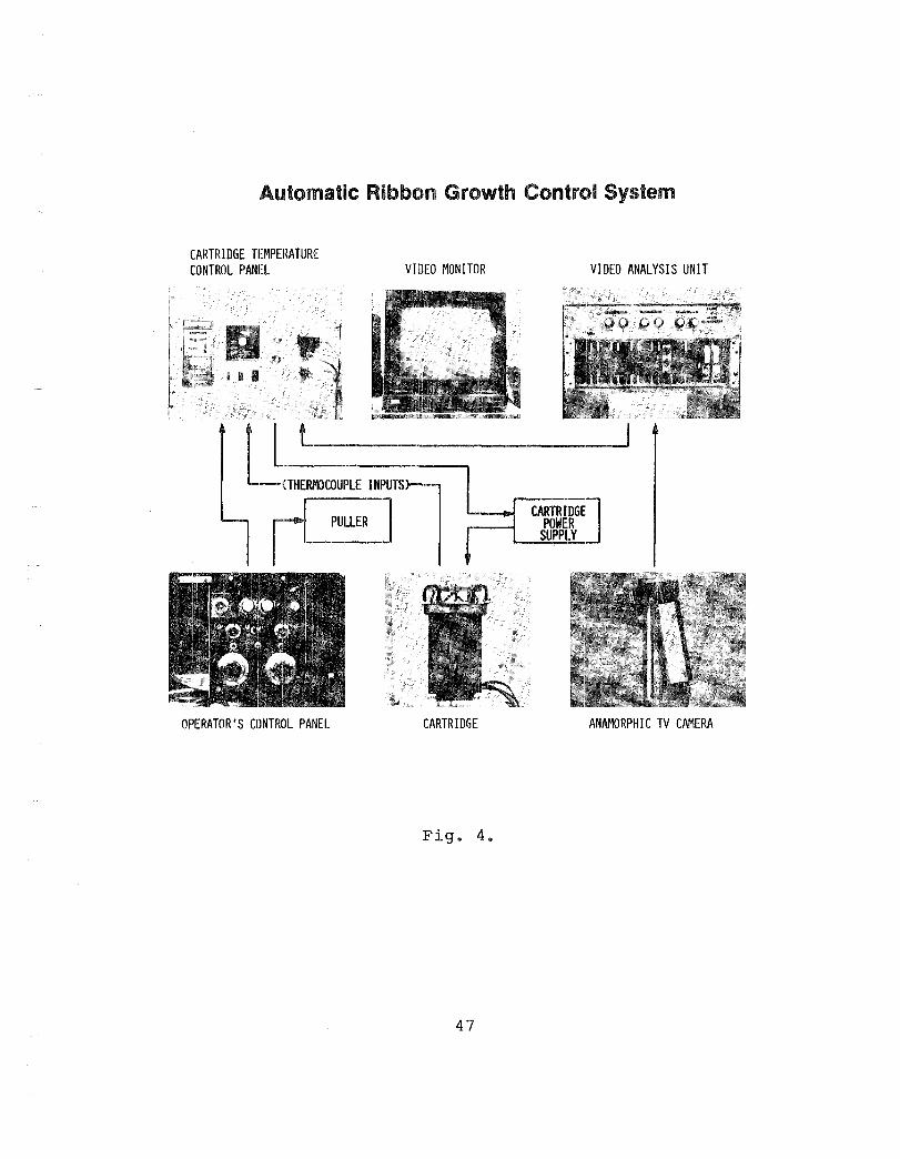
~
l I
Automatic Ribbon Growth Contrc»1 System
CARTRIDGE TEMPEllATURE CONTROL PANEL
~ PULLER I
OPERATOR'S CONTROL PANEL
VIDEO MONITOR
CARTRIDGE
Fig. 4.
47
VIDEO ANALYSIS UNIT
CARTRIDGE]. POWER SUPPIL
ANAMORPHIC TV CAMERA
These runs, of which three were attempted, revealed two significant problems, which caused the machine to fall far short of its throughput goals. The first of these was a number of minor component misfits and maladjustments, in the main, simply quality control problems. Those arose from the fact that substantial portions of the overall machine, only recently developed in single-cartridge experiments, had to be duplicated in a short time to similarly outfit the second and third growth stations.· The second problem which had a severe impact on the yield of ribbon from our attempted Technical Features Demonstration runs ·was the distortion of isotherm shape at the die tops in the cartridges occupying positions 2 and 3 in the furnace. It became quite clear from these experiments that irregularities in the temperature profile of the main furnace are the cause. These irregularities had no significant effect when the 5 cm cartridges were run in multiple mode a year ago, and were not encountered until recently because in all developmental work the 10 cm cartridge has been operated singly in furnace position 1. It came as no surprise that, in all three recent multiple runs, cartridge 1 worked quite well. It was totally unexpected that cartridges 2 and 3 would be virtually unable to produce any full-width ribbon.
The sensitivity of the 10 cm growth cartridge to hot zone profile irregularities illustrates the general point that, although its design is derived directly from that of the 5 cm cartridge, the requirements for optimization of function and precision of its parts are considerably more stringent. The width of the central portion of the die which is out of range of the trimming influence of the heaters is about four times as great as in the 5 cm cartridge. A particularly severe problem is the elastic stress induced in the 10 cm wide ribbon by the transition between the afterheater region, ending at SSOoC, and room temperature. Factors which cause the ribbon to be grown with irregular thickness profiles, such as the distortions of die-top isotherms present in the attempted Technical Features Demonstration runs, cause these elastic stresses to be concentrated in thin sections, and result in a great deal of ribbon breakage in the cartridges. A partial solution to this problem would be to extend the linear cooling section of the cartridge upward, to end at a lower temperature. Although a straightforward matter of redesign, this change was too radical to have been undertaken within the tight timetable of preparation for the Technical Features Demonstration.
The photovoltaic performance of material from the multiple 10 cm EFG ribbon furnace is currently unknown. It has been historically true of all EFG ribbon growing units that the quality of the material does not reach its potential, and cannot even be assessed, until the design and operating procedures have been fixed and the infrastructure has been set up to support fully-clean operation of the system for several identical runs. The 10 cm multiple furnace has not yet been operated under these conditions. Among the .few solar cells which have been made from its ribbon, the figure of 8~ efficiency has been surpassed. We'
48
expect that, in routine growth, the quality of material from this furnace would level off at the same 9+~ efficiency level as has been produced by other all-graphite EFG systems in which there is no provision for adding oxygen to the silicon. However, recent experiments have shown that the photovoltaic output of material grown from cartridge systems can be ~aised to well over 11~ efficiency by proper manipulation of the gas ambient of the growing ribbon, as well as the solar cell fabrication sequence. Thus, a task that must be undertaken in the near future in this project is to engineer the features to control the gas ambient in the proper way into reliable, production-worthy hardware.
The following summary describes the status of the Mobil Tyco multiple EFG ribbon machine with regard to its goals for demonstration of combined technical features.
In slightly a year since its introduction, the 10 cm ribbon cartridge has been developed to the point where it will reliably produce solar cell ribbon at over 4 cm/min when operated in the generally flat thermal profile of position 1 of the multiple furnace, or in a single ribbon furnace.
Recent attempts to grow ribbon from cartridges in positions 2 and 3 of the present furnace have revealed that the 10 cm unit is much more sensitive to local irregularities of temperature distribution in the main furnace than was the 5 cm cartridge. and hence some effort must be devoted to refining the furnace's temperature profile.
We now have an optically-based automatic control system which. even with relatively little optimization since it was installed, effectively maintains growth without any operator attention for typical periods of two to three hours. The system appears sufficiently reliable and easy to set up to be considerable production-worthy.
A serious problem exists with the 10 cm growth system in ribbon breakage due to thermal stresses at the transition between the imposed linear cooling profile. and room temperature: However, the solution to this problem appears straightforward.
The process has not yet begun of engineering into the multiple ribbon furnace the means for adding oxygen to the melt, a factor which has been shown in other EFG growth systems to contribute to the attainment of photovoltaic efficiencies of over 13~.
In fact then, in spite of the lack of a "Technical Features Demonstration". much of the general knowledge needed to advance the technology further has now been delineated. and further progress can be made by executing the necessary design changes and testing them.
49
This topic has always given rise to great concerns for the simple reason that EFG ribbon commonly contains a variety of linear and planar crystallographic defects, such as coherent and incoherent twins, as well as significant densities of dislocations. Furthermore, high concentrations of carbon are also present. It is equally well recognized that EFG ribbon is formed under conditions which make a net segregation coefficient near one for most impurities quite likely.
In a general way then, this suggests that obtaining solar cell efficiencies in the 13+~ range from such material might not be possible.
However, as mentioned above, efficiencies of selected cells of small area, grown from quartz crucibles in single ribbon (2.5 cm wide) machines, showed efficiencies as h~gh as 14~ on some occasions, and very large area cells (55 cm ) from 7.5 cm wide ribbon had also climbed toward the 10~ mark by the end of 1979.
However, a clear demonstration that ribbons grown from resistance-heated machines could also achieve efficiencies around 13~ was still missing. A variety of reasons, singly and in combination, was held to be responsible for this. This list included suggestions that the equipment itself causes generally higher levels of impurity in these ribbons when compared with quartz crucible-grown ribbons, or that special crystallographic defects are introduced during the heating-cooLing-heating cycle attendant to high-speed growth. Most of the questions raised are, in a fundamental sense, still unanswered, but the work in 1979 already showed that gains in quality are possible by systematically studying the growth variables.
With the start of the gas ambient experiments, though (run 143 in Fig. 2), it became clear quite quickly that one variable, namely the oxygen content, which had been suspected for some time to contribute to improved quality of quartz-grown ribbon, was totally uncontrolled in the cartridge-grown ribbon which is prepared generally from graphite crucibles. It was shown then that by supplying the meniscus area with oxygen-containing gases, in particular CO2 , the electronic properties of the ribbon could be significantly improved.
Since much of this work was discussed in detail during the last PIM and will also presently appear in the open literature, let me mention here only some significant additional results as they have recently been obtained from a detailed investigation of the response of ribbons to heat treatment.
The major analytical method employed in this inve~tigation is 2n evaluation of the minority carrier diffusion
50
length in the base of finished solar cells using an infrared photovoltage method, which also allows measurement of the dependence of the diffusion length on photon flux. These values are compared with diffusion length data on the starting material, obtained by a surface-photovoltage technique using aluminum Schottky barriers.
The ribbons (nominally 1 O-cm boron do~ed, p-type material) are processed by open tube diffusion into n p solar cells u~ing a phosphine (PH~) source at temperatures between 850 and 1050 C for 30 minutes and then furnace cooled to 600 0 C in five hours after which time they are removed to room temperature.
These measurements are supplemented by standard infrared absorption studies which allow determination of the substitutional carbon and interstitial oxygen concentration before and after solar cell processing, and by efficiency measurements on solar cells diffused in the same general temperature range as mentioned above, but under conditions which lead to optimized junction depths.
Table X presents averaged solar cell efficiencies for 20 cells from each group of materials investigated.
It is clear that both the short circuit currents and open circuit voltages are distinctly better for cells fabricated from material grown in the presence of large oxygen concentrations (OR material). This efficiency advantage holds for both the quartz crucible-grown and the CO2-treated ribbon, which were grown at times separated by nearly two years and from equipment of totally different construction.
The materials grown under oxygen lean (OL) conditions, also separated in time by two years, also show great similarities in photovoltaic behavior, and for these materials cells of clearly lower performance are obtained.
An example of the behavior of the diffusion length as a function of photon flux in cells from this sample is shown in Fig. 5 and the remarkable similarity between the quartz crucible-grown and the CO2-treated material is quite apparent here, as is the distinctly weaker rise of the diffusion length with photon flux for the material grown from graphite crucibles.
Figure 6 presents the results of an experiment which was intended to detail the influence of diffusion temperature. To facilitate any possible complex formation, the cooling time from the diffusion temperature to 600°C was chosen to be approximately five hours. Also. these experiments were carried out only on ribbon grown from resistance-heat equipment either without (OL) or with (OR) the addition of CO2 to the atmosphere surrounding the meniscus area during growth.
51
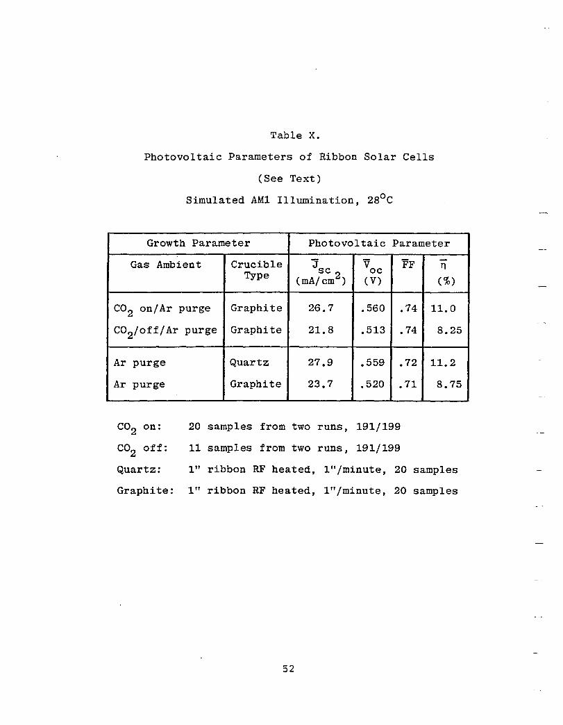
Table x.
Photovoltaic Parameters of Ribbon Solar Cells
(See Text)
Simulated AM1 Illumination, 280 C
Growth Parameter Photovoltaic Parameter
Gas Ambient Crucible J V FF -n Type sc 2 oc
(mA/cm ) (V) (%)
CO2 on/Ar purge Graphite 26.7 .560 .74 11.0
CO2/off/Ar purge Graphite 21. 8 .513 .74 8.25
Ar purge Quartz 27.9 .559 .72 11.2
Ar purge Graphite 23.7 .520 .71 8.75
CO2 on: 20 samples from two runs, 191/199
CO2 off: 11 samples from two runs, 191/199
Quartz: 1" ribbon RF heated, l"/minute, 20 samples
Graphite: 1" ribbon RF heated, l"/minute, 20 samples
52
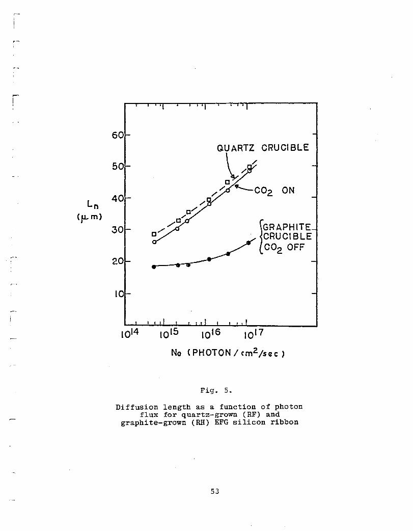
r-!
r-
I I
Ln (p-m)
~
:
ON 40
/ 0/
.;
/0 30 0""" [GRAPHITE
. CRUCIBLE CO2 OFF
20
10
1014
No (PHOTON/rm2 /sczc)
Fig. 5.
Diffusion length as a function of photon flux for quartz-grown (RF) and
graphite-grown (RH) EFG silicon ribbon
53
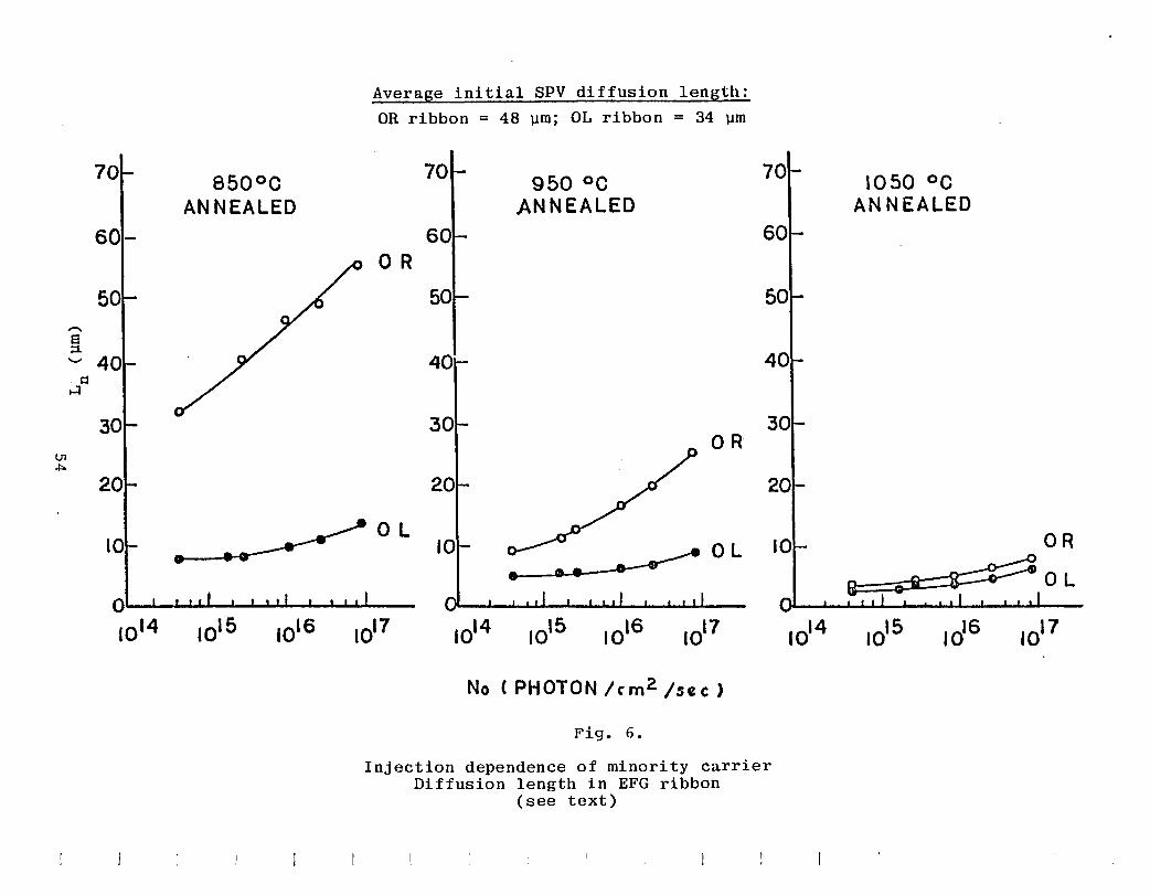
'""' 8 ;:1
70
60
50
'-' 40
850°0 ANNEALED
Average initial SPV diffusion length:
OR ribbon = 48 ~m; OL ribbon = 34 ~m
OR
OL
950°C ANNEALED
OR
70
OLIO
O~--~u-~~~~~~----
1014
No ( PH OT 0 N / c m 2 / sec )
Fig. 6.
Injection dependence of minority carrier Diffusion length in EFG ribbon
(see text)
1050 °C ANNEALED
Qualitatively then, the results for the 950 0 C diffusion temperature are indeed very similar to the results in Fig. 5, which were obtained from material grown at other times, clearly indicating the generality of these phenomena. It becomes however also clear that the initial dark diffusion lengths in the as-grown material are quite generally reduced for all cell diffusion temperatures. However, the presence of oxygen during growth quite apparently not only buffers the decrease in the dark diffusion length at the lower processing temperatures, but also engenders a much larger increase in L with photon flux, the net effect being that far better solar celfs result from "oxygenated" material processed at lower temperatures.
The infrared measurements which were undertaken here are somewhat limited by the fact that these ribbon samples are quite thin (200 to 250 ~) and therefore the detection limits for carbon (CS ') and oxygen (0.) are somewhat high, even when liquid nitrogen tem~eratures are us~d. However, all the ribbons investigated here contain substitutiona!Scarbon ley~ls very near the solid solubility limit (-10 atoms-cm ) with no significant changes detected after processing.
ThI6detection_~imit for oxygen in our experiments lies around -2 x 10 atoms-cm ,and in many cases levels over that limit can be detected in t£g quartz-g;~wn ribbon, with occasionally very high levels (-10 atoms-cm ) being seen. The most general statement that can be made, though, is that the interstitial oxygen content in ribbons grown from quartz crucibles is often inhomogeneously distributed as well as being quite erratic from ribbon to ribbon.
When CO is bled into the purge gas around the meniscus during growt6 of 5 cm wide ribbon at slow speeds however, quite reprod~9ible cont~gts of interstitial oxygen in the range of 2 to 5 x 10 atoms-cm result.
In a phenomenological sense, the results obtained are quite clear. Oxygen introduction during growth promotes increased minority carrier diffusion length in solar cells produced at the lower fabrication temperatures, and, as a consequence, much better conversion efficiencies are obtained from such oxygen-treated EFG ribbon, particularly when appropriate thermal treatments are used during cell preparation.
When one compares the results of the heat treatments at various temperatures, both for ribbons grown without the presence of oxygen, and ribbons grown in the presence of oxygen, it also becomes quite logical to conclude that the differences seen are indeed due to the presence of oxygen in the ribbon. This conclusion can, of course, be confirmed by the' fact that the ribbons which have been grown in the presence of CO always contain detectable concentrations of interstitial o~ygen,
55
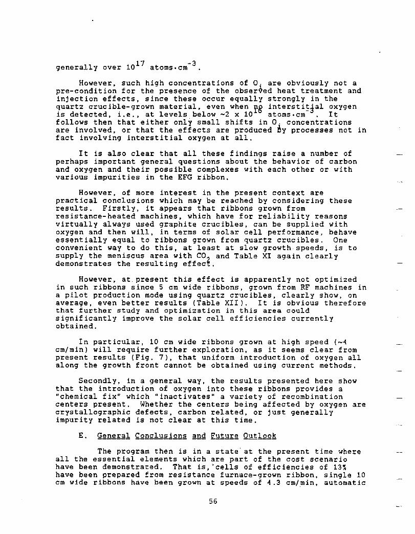
17 -3 generally over 10 atoms.cm .
However, such high concentrations of O. are obviously not a pre-condition for the presence of the obser~ed heat treatment and injection effects, since these occur equally strongly in the quartz crucible-grown material, even when rg intersti~~al oxygen is detected, i.e., at levels below -2 x 10 atoms.cm . It follows then that either only small shifts in O. concentrations are involved, or that the effects are produced ~y processes not in fact involving interstitial oxygen at all.
It is also clear that all these findings raise a number of perhaps important general questions about the behavior of carbon and oxygen and their possible complexes with each other or with various impurities in the EFG ribbon.
However, of more interest in the present context are practical conclusions which may be reached by considering these results. Firstly, it appears that ribbons grown from resistance-heated machines, which have for reliability reasons virtually always used graphite crucibles, can be supplied with oxygen and then will, in terms of solar cell performance, behave essentially equal to ribbons grown from quartz crucibles. One convenient way to do this, at least at slow growth speeds, is to supply the meniscus area with CO 2 and Table XI again clearly demonstrates the resulting effect.
However, at, present this effect is apparently not optimized in such ribbons since 5 em wide ribbons, grown from RF machines in a pilot production mode using quartz crucibles, clearly show, on average, even better results (Table XII). It is obvious therefore that further study and optimization in this area could significantly improve the solar cell efficiencies currently obtained.
In particular, 10 em wide ribbons grown at high speed (-4 em/min) will require further exploration, as it seems clear from present results (Fig. 7), that uniform introduction of oxygen all along the growth front cannot be obtained using current methods.
Secondly, in a general way, the results presented here show that the introduction of oxygen into these ribbons provides a "chemical fix" which "inactivates" a variety of recombination centers present. Whether the centers being affected by oxygen are crystallographic defects, carbon related, or just generally impurity related is not clear at this time.
The program then is in a state' at the present time where all the essential elements which are part of the cost scenario have been demonstrated. That is,~cells of efficiencies of 13~ have been prepared from resistance furnace-grown ribbon, single 10 cm wide ribbons hav~ been grown at speeds of 4.3 em/min, automatic
56
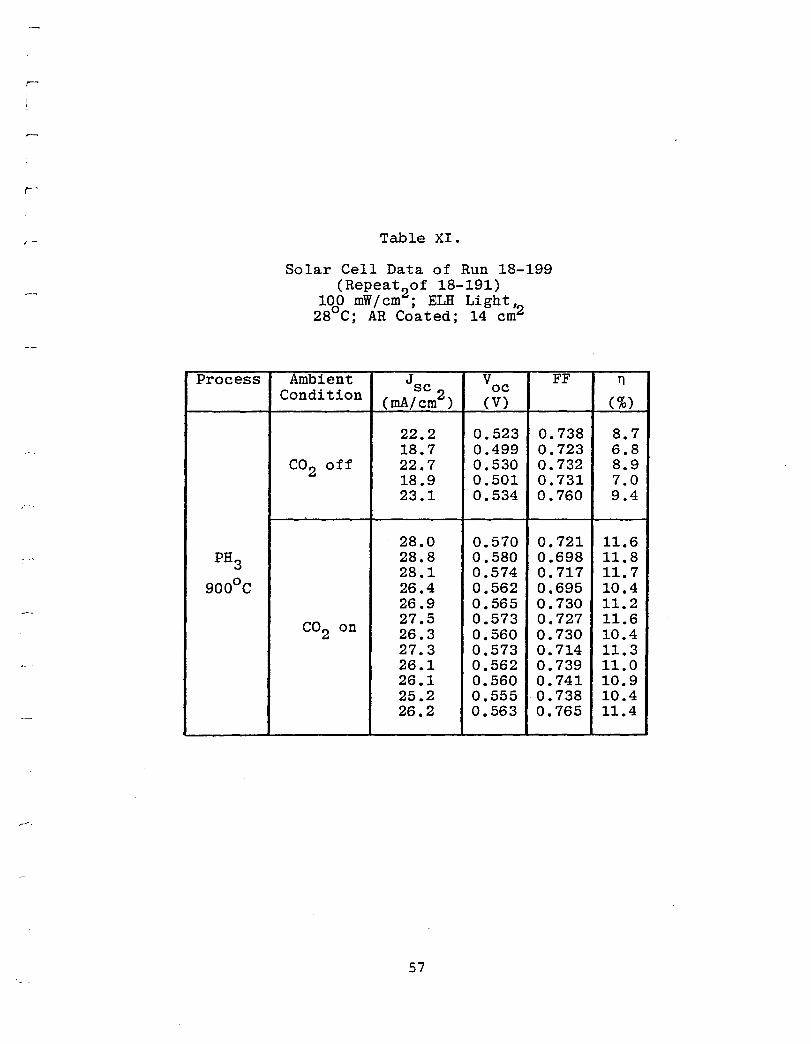
r -
Process
,-
PH3
9000
C
Table XI.
Solar Cell Data of Run 18-199 (Repeat of 18-191)
1000 mW / cm
2 ; ELH Li gh t '2
28 C; AR Coated; 14 cm
Ambient Jsc V FF Condition oc
(mA/cm2 ) (V)
22.2 0.523 0.738 18.7 0.499 0.723
CO2 off 22.7 0.530 0.732 18.9 0.501 0.731 23.1 0.534 0.760
28.0 0.570 0.721 28.8 0.580 0.698 28.1 0.574 0.717 26.4 0.562 0.695 26.9 0.565 0.730
CO2 on 27.5 0.573 0.727 26.3 0.560 0.730 27.3 0.573 0.714 26.1 0.562 0.739 26.1 0.560 0.741 25.2 0.555 0.738 26.2 0.563 0.765
57
11
(%)
8.7 6.8 8.9 7.0 9.4
11.6 11.8 11.7 10.4 11.2 11.6 10.4 11.3 11.0 10.9 10.4 11.4
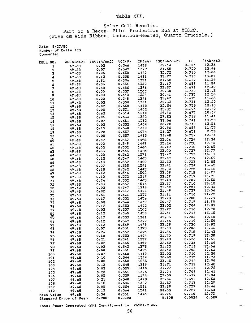
Table XII.
Solar Cell Results. Part of a Recent Pilot Production Run at MTSEC.
(Five cm Wide Ribbon, Induction-Heated, Quartz Crucible. )
Dat.e 9/27/80 N'Ja,oer of Cells 123 Coa,a,ents:
CELL NO. AREACCII,2) I RV C a,AI ea,2) VQC(V) IPCa,A', ISC(a,A/ea,2) FF F' C ",W / ea,2)
1 49.68 0.03 0.546 1428 32.14 0.704 12.36
2 49.69 0.07 0.549 1399 31.55 0.720 12.46
3 49.68 0.05 0.550 144C 32.n 0.715 12.86
4 49.68 0.12 O.S~B 1431 32.77 0.712 13.01
5 49.68 1.91 0.536 1331 31.38 0.677 11.39 6 49.68 0.36 0.551 1360 31.17 0.689 11.84
7 49.68 0.48 O.5SS 1396 32.37 0.691 12.42
8 49.68 0.00 0.55; 1502 32.30 0.732. 13.15 9 49.68 0.08 0.548 1384 30.41 0.735 12.26
10 49.66 0.00 0.548 1346 31.47 0.675 11.63
11 49.68 0.03 0.550 1381 30.33 0.731 12.20
12 49.t.8 0.02 0.558 1438 32.54 0.7:3 13.13
13 49.68 0.08 0.551 1402 3:!.3:! 0.696 12.40
14 49.68 0.63 0.514 1244 28.96 0.677 10.09
15 49.68 0.05 0.533 1332 29.82 0.718 11.41
16 49.68 0.07 0.551 1532 33.06 0.741 !3.S0
17 49.68 0.03 0.5S2 1404 30.78 0.740 12.56
18 49.68 0.15 0.540 1340 30.96 0.689 11.5"3
19 49.68 0.28 0.557 1074 26.27 0.651 9.53
20 49.68 0.08 0.557 1415 31.48 0.727 12.74 • 60 49.68 0.02 0.557 1498 33.06 0.724 13.34
61 49.68 0.02 0.549 1449 32.24 0.728 12.90 62 49.68 0.02 0.552 1460 32.42 0.716 12.85 63 49.68 0.03 0.566 1475 33.00 0.737 13.77 64 49.':8 0.00 0.562 1571 33.47 0.753 14.17 65 49.t8 0.15 0.547 1405 32.02 0.719 12.59 66 49.1'.8 v.13 0.552 1422 32.32 0.n3 12.88 67 49.68 0.07 O.5~5 1541 33.41 0.7::4 13.62 68 49.6a 0.18 0.562 1442 32.34 0.725 13.18 69 49.(.8 0.12 0.546 1502 33.09 0.718 12.97 70 49, .8 0.12 0.552 1517 33.29 0.719 13.21 71 49.68 0.74 0.552 1405 32.48 0.701 1:!.58
72 49.68 0.03 0.557 1516 33.37 0.710 13.18 73 49.'·6 0.02 0.~47 1396 31.59 0.721 12.4.6
74 49.68 0.02 0.547 1403 31.49 0.729 12.56
75 49.{.8 0.51 0.531 1355 31.11 0.710 11.72
76 49.68 0.17 0.552 1456 32.78 0.705 12.74 77 49.e.8 0.08 0.544 1362 30.47 0.719 11.90 78 49.68 0.12 0.552 1422 33.02 0.704 12.83 79 49 ... 8 0.03 0.557 1502 32.77 0.710 12.98
~~ 49.t8 0.12 0.565 1450 32.61 0.714 13.15 49ol8 0.17 0.553 1381 31.35 0.703 12.18
91 49.i.8 0.12 0.549 1399 31.65 0.719 12.50 92 49.68 0.12 0.569 1479 33.29 0.730 13.83 93 49.68 0.07 O.~~l 1398 32.03 0.706 12.46 94 49.68 0.26 0.552 1395 31.36 0.718 12.43 95 49.68 0.10 0.552 1404 31.70 0.719 12.58 96 .. 9.68 0.21 0.541 1339 31.48 0.676 11.51 97 49.68 0.02 0.::;65 1459 32.50 0.736 13.50 98 49.68 0.02 0.543 1375 31.25 0.711 12.06 99 49.68 0.08 0.551 1425 32.40 0.702 12.53
100 49.68 0.07 0.550 1419 32.02 0.710 12.50 101 49.68 0.10 0.544 1364 30.69 0.715 11.93 102 49.68 0.00 0.558 1555 33.45 0.744 13.90 103 49.68 0.13 0.548 1399 31.71 0.718 12.48 104 49.68 0.03 O.S~5 1440 31.77 0.723 12.75 105 49.68 0.20 0.551 1395 31.74 0.109 12.41 106 49.68 0.05 0.539 1174 27.50 0.677 10.04 107 49.68 0.21 0.548 1478 32.86 0.697 1~.56
108 49.68 0.18 0.546 1387 31.57 0.713 12.29 109 49.68 0.05 0.554 1531 33.39 o.ni 13.46 110 49.68 0.13 0.564 1541 33.53 0.721 13.64
Mean Value 49.68 0.54 0.551 1416 31.95 0.710 12.5: Standard Error of Mean 0.:!08 0.0008 0.108 0.0024 0.080
Total Power Generat.ed CAM1 Condit.ions) is 76501.9 atLl •
58
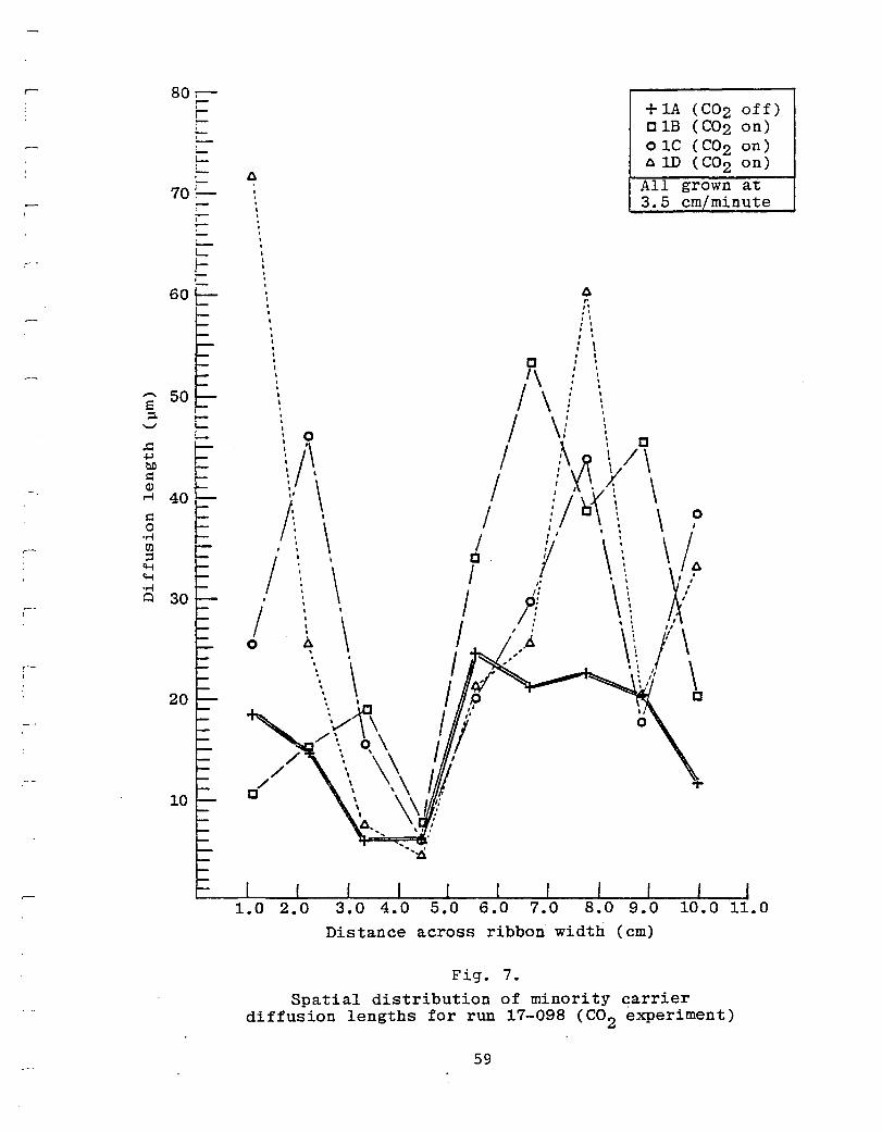
-!
,-. E ;:l.
'-../
.c: ~ bO ~ Q) ~
~ 0
'''; en ;j 'H 'H '''; Q
,
,-I
80-, --r-L
'--r-!
70 : -I
I r
L-
F 60 I
L
50
30
10
6 , , , , , , , , , , , , , , , , ,
, , , I I
• I .
~ ,. " .' • I , ,
• I , , : \ I ,
~\ ! \
+1A (C02 off) C 1B (C02 on) o 1C (C02 on) 61D (C02 on) All grown at 3.5 em/minute
/ \ j \
o / \! , C
\'\ / :\R\/\ \/' : X' y
I:, \ / !j\ X' \ \
, \, '\ /: C\: \ ~ . J I' \ \ \ /6
/ ': \\ ! II \ \ '1/ o ~. I .. > \\ I' \
'\ I ~~1 . \ /1 \ ~ I t;){ ~, \ I j:;) C
\/'r\ I / /\, ~ \ I r
\~\ I¥ \\l/
I , .
Distance across ribbon width (em)
Fig. 7.
Spatial distribution of minority carrier diffusion lengths for run 17-098 (C02 experiment)
59
controls have been developed and tested, and long-term multiple ribbon growth has occurred on several occasions during the course of the program, with both 5 cm and 10 cm wide ribbon being grown.
All this has to be counted as very significant progress toward the LSA goals, particularly against the background of doubt about the EFG method that had been raised in many quarters, especially so far as the probability of achieving multiple operation in wide ribbon growth and improvement of cell efficiencies to the 13~ range were concerned. In the materials quality area also, several exciting avenues have been opened recently with the discovery of the gas ambient/oxygen effects, which clearly suggest that further advances will be made.
However at the present time, the program is behind schedule, inasmuch as the full "Technical Features Demonstration", which has been set for July 1980, has not yet occurred. It is nevertheless our opinion that this is a rather minor setback, which could be easily overcome by another design iteration of the present equipment. But that would seem to be a waste of effort, as more progress could be achieved if such a design effort were to be directed toward part of the equipment which would in fact be used to achieve the ultimate goals of the program. In other words, we suggest that information accumulated by now, in conjunction with the general background of expertise at Mobil Tyco, will allow an orderly schedule to be designed which has a reasonable chance to prove the "readiness" of this technology at the end of fiscal year 1983.
Such an effort, however, will require funding at least at the present level until 1983, as well as a most efficient execution of the program, which would have to include a very precise definition of what is to be achieved at the point of "technology readiness", in order to have any chance of success.
Thus, after more than three further years of development, we can only repeat the conclusions of the 9th PIM, namely that there are no fYng~~n~sl technical obstacles which would suggest that the goals of Task II of the LSA program cannot be achieved with EFG technology.
60
The design and construction of a new multiple ribbon furnace for growth of 10 cm wide ribbon was undertaken in early 1981 when it became evident that the reconfigured Furnace 16 (JPL No. 3A) would not be capable of fulfilling the Technical Features Demonstration goals set for it in 1990 without a major redesign effort. These goals called for a multiple ribbon growth run of eight hours, a growth rate of 4.5 cm/min, a machine duty rate of 85~ or better, operational automatic controls on one ribbon, and a ribbon quality su.fficient for 10.2~ cell efficiency. The shortfall in meeting these goals was shown to be caused partly by cartridge-related deficiencies, and partly by main zone furnace inadequacies. The program plan for 1981 accordingly called for optimization work on the cartridge with respect to growth performance and ribbon quality to continue in single cartridge furnaces during the construction phase of the new furnace. Prior to proceeding with this course of action, a standardization of cartridge components, and main zone configuration, insofar as was possible, was carried out to place cartridge performance in both multiple and single cartridge furnaces on a comparable level. The elements of design that are to be incorporated into development of the new multiple ribbon furnace are examined in more detail next. Main furnace and cartridge-related topics are discussed under separate headings.
The new multiple furnace allows for growth of four 10 cm wide ribbons, as compared to three for the original Furnace 16. A more symmetric configuration is achieved by locating two cartridges on either side of a central melt replenishment unit. The new furnace is shown in the photograph in Figure 1. The target operating growth speed has been lowered to 4 cm/min from the previous 4.5 cm/min, and the extra cartridge provides more than the necessary compensation for the decreased areal throughput resulting from this speed reduction. The lower growth speed has been shown to be attainable with the existing cooling capabilities in the cartridge already in use, and thus limits the experimentation necessary to improve performance to acceptable levels only to optimization studies.
A new melt replenishment unit was incorporated into the updated furnace design. The original design had proved to be unreliable when pushed to the limit even for supplying silicon for growth of three 10 cm wide ribbons. The new unit has the capability to provide for growth of four ribbons, and utilizes silicon chips rather than the specially shaped solid charge rods used in the old unit.
Additional changes· that have been incorporated into the new furnace design improve main zone insulation, the furnace jacket cooling arrangement, and new power supplies to provide for more
61
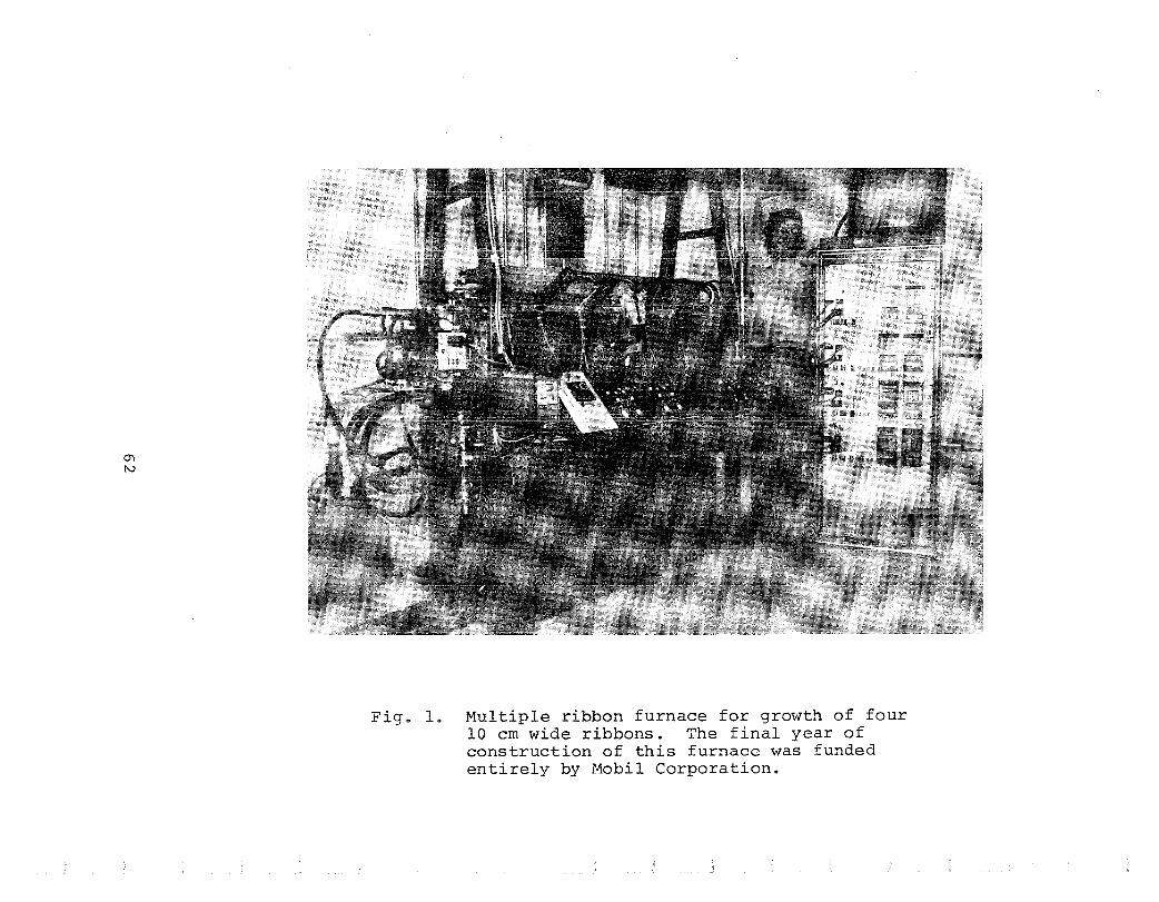
Fig. 1. Multiple ribbon furnace for growth of four 10 cm wide ribbons. The final year of construction of this furnace was funded entirely by Mobil Corporation.
efficient operation of the main zone.
The outstanding factor contributing to the productivity shortfall in multiple ribbon growth demonstration runs in 1980 was related to seed ribbon breakage. This breakage occurred frequently enough to cause appreciable loss of growth time and cartridge performance degradation due to broken silicon seed pieces melting on the die and becoming jammed in the growth slot. The cause of this was recognized as stress increases in seeds being inserted into the upper regions of the cartridge growth slot caused by an abrupt decrease in temperature at the cartridge exit. A new elongated or "stretched" cartridge has been designed to change the temperature profile at the linear cooling plate termination, as illustrated in Figure 2.
Testing and characterization of the elongated cartridge was carried out in the single ribbon Furnace 17 during 1981. Goals were to improve growth stability and thickness uniformity at the target levels of 4 em/min and 200 ~m, respectively, and characterize differences in temperature fields of various cartridge designs to aid in stress analysis studies. Among the desigrt variations investigated have been: (1) profiling the linear cooling plate to alter its cross section across the ribbon width; (2) changing the geometry of the growth slot constriction formed by the inside surfaces of the linear cooling plates, i.e., the growth slot dimensions; (3) relocating the afterheater; and (4) increasing the length of the cooling zone of the cartridge. Although the longer linear cooling plate design was originally conceived to counter seed breakage, a significant reduction of the buckle amplitude and of residual stress levels was observed immediately in ribbon grown with this cartridge. However, several other changes in the linear cooling plate and afterheater configuration were made in this cartridge in addition to lengthening the cooling zone, and consequently the cause for the improvements were not immediately evident.
To fully characterize the cartridge temperature fields resulting from the design changes, temperature profiling of the linear cooling plates was undertaken. The primary purpose of these measurements was to monitor center-to-edge temperature differences. It has been suggested that proper manipulation of horizontal isotherms may allow compensation for and reduction of stresses caused by curvature of the vertical temperature profile.
Data typical of that obtained in the region of the afterheater, i.e., the maximum temperature point of the reheat region, are compared for several cartridge design variations in Figure 3. The "standard" configuration denotes the normal length linear cooling plate system of Figure 2(a), the "reduced stress" configuration is that of Figure 2(b). Center-to-edge temperature drops across the cartridge width are observed in all cases, with
63
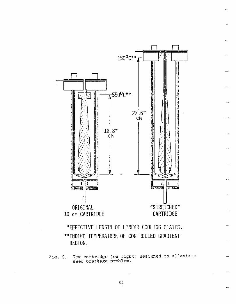
ORIGINAL
18,8* CM
10 CH CARTRIDGE
2
I
7,6* CM
,
n n ~' .~ \ ,
ij il j
« i rc H ~l iii ~! ~ '" 11 .~ I~ ~ I ,
~ , ~
n , Ii ~ J
~ .. , ... / I
r~ \ / I ~ I
I. 1.~ 1
~ II \ I 'I I. , p, \\ I ~ t~ . Ii
., I, \
II i ~~ ~, . \
~ 0 ,1 ,/j \\ tJ '/ I \\ ~ !~ I, ,\
i" I ! / \ J
"STRETCHED" CARTRIDGE
*EFFECTIVE LENGTH OF LINEAR COOLING Pu\TES I
**ENDING TEMPERATURE OF CONTROLLED GRADIErH REGION.
Fig. 2. New cartridge (on right) designed to alleviate seed breakage problem.
64
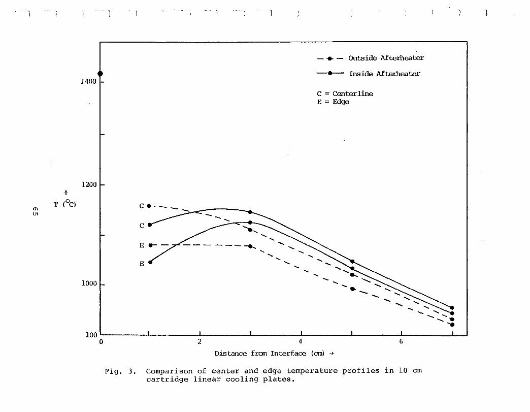
t
T m
(oC) lJ1
--- )
1400
1200
---C
E ----.,..
E .....
1000
- .. - Outside Afterileater
• Inside Afterileater
C = Centerline E = Edge
..... ---. ---- - --
" ,
100~-------L---------L---------L--------~--------~--------L-----____ L-~ o 2 4
Distance frem Interface (em) -+
6
Fig. 3. Comparison of center and edge temperature profiles in 10 em cartridge linear cooling plates.
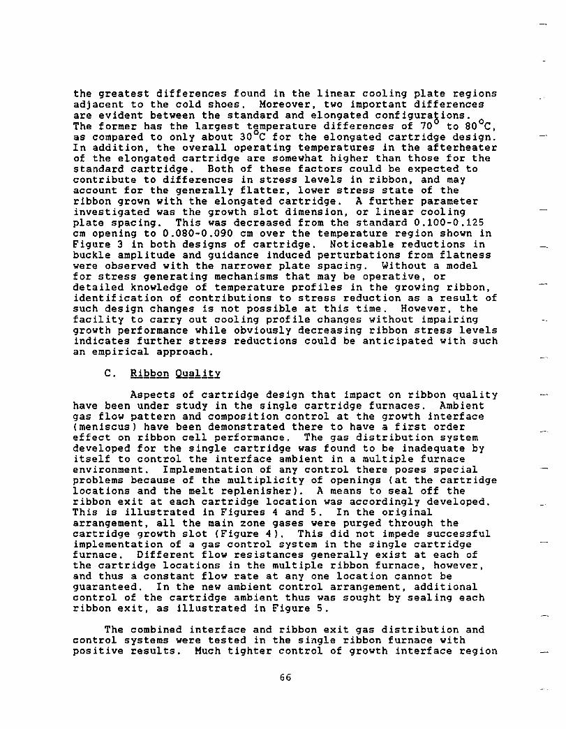
the greatest differences found in the linear cooling plate regions adjacent to the cold shoes. Moreover, two important differences are evident between the standard and elongated configurations. The former has the largest temperature differences of 70 0 to 80 0 C, as compared to only about 30 0 C for the elongated cartridge design. In addition, the overall operating temperatures in the afterheater of the elongated cartridge are somewhat higher than those for the standard cartridge. Both of these factors could be expected to contribute to differences in stress levels in ribbon, and may account for the generally flatter, lower stress state of the ribbon grown with the elongated cartridge. A further parameter investigated was the growth slot dimension, or linear cooling plate spacing. This was decreased from the standard 0.100-0.125 cm opening to 0.080-0.090 cm over the temperature region shown in Figure 3 in both designs of cartridge. Noticeable reductions in buckle amplitude and guidance induced perturbations from flatness were observed with the narrower plate spacing. Without a model for stress generating mechanisms that may be operative, or detailed knowledge of temperature profiles in the growing ribbon, identification of contributions to stress reduction as a result of such design changes is not possible at this time. However, the facility to carry out cooling profile changes without impairing growth performance while obviously decreasing ribbon stress levels indicates further stress reductions could be anticipated with such an empirical approach.
Aspects of cartridge design that impact on ribbon quality have been under study in the single cartridge furnaces. Ambient gas flow pattern and composition control at the growth interface (meniscus) have been demonstrated there to have a first order effect on ribbon cell performance. The gas distribution system developed for the single cartridge was found to be inadequate by itself to control the interface ambient in a multiple furnace environment. Implementation of any control there poses special problems because of the multiplicity of openings (at the cartridge locations and the melt replenisher). A means to seal off the ribbon exit at each cartridge location was accordingly developed. This is illustrated in Figures 4 and S. In the original arrangement, all the main zone gases were purged through the cartridge growth slot (Figure 4). This did not impede successful implementation of a gas control system in the single cartridge furnace. Different flow resistances generally exist at each of the cartridge locations in the multiple ribbon furnace, however, and thus a constant flow rate at anyone location cannot be guaranteed. In the new ambient control arrangement, additional control of the cartridge ambient thus was sought by sealing each ribbon exit, as illustrated in Figure 5.
The combined interface and ribbon exit gas distribution and control systems were tested in the single ribbon furnace with positive results. Much tighter control of growth interface region
66
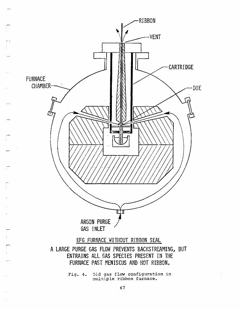
,--
I ,
FURNACE CHAMBER
ARGON PURGE GAS INLET
EFG FURNACE WITI~OUT RIBBON SEAL
CARTRIDGE
A LARGE PURGE GAS FLOW PREVENTS BACKSTREAMING J BUT ENTRAINS ALL GAS SPECIES PRESENT IN THE
FURNACE PAST MENISCUS A~m HOT RIBBON.
Fig. 4. 01d gas flow configuration in multi.ple ribbon furnace.
67
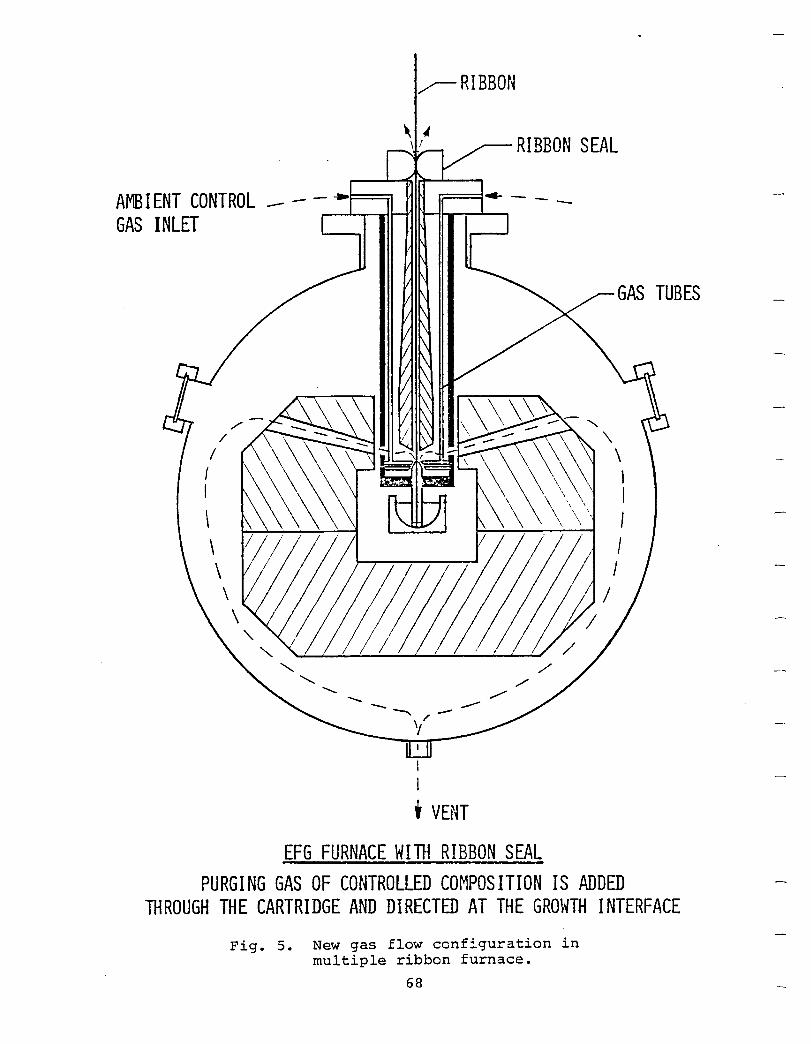
~RIBBON
\, ~ .....--., .. 1_ --. RIBBON SEAL
AMB I ENT CONTROL _ - - .. t==:;,
GAS INLET '---M II\L-J
I I
, VENT
EFG FURNACE WITH RIBBON SEAL PURGING GAS OF CONTROLLED COMPOSITION IS ADDED
THROUGH THE CARTRIDGE AND DIRECTED AT THE GROWTH INTERFACE
Fig. 5. New gas flow configuration in multiple ribbon furnace.
68
ambient gases was evident, and furnace operation was carried out with greatly reduced total argon purge rates without appearance of harmful air penetration of the furnace. Optimization of ambient conditions was required to achieve satisfactory cell performance with the new gas control configuration. In the course of this work, significant increases in large area cell efficiency were obtained. The best results with the new gas distribution system and the elongated cartridge are compared to previous data in Table I. For the first time, large area cell efficiencies of over 11~ were attained in ribbon grown at 3.5 em/min with cold shoes. Cell efficiencies averaged over a number of runs were between 10 and 11~.
69
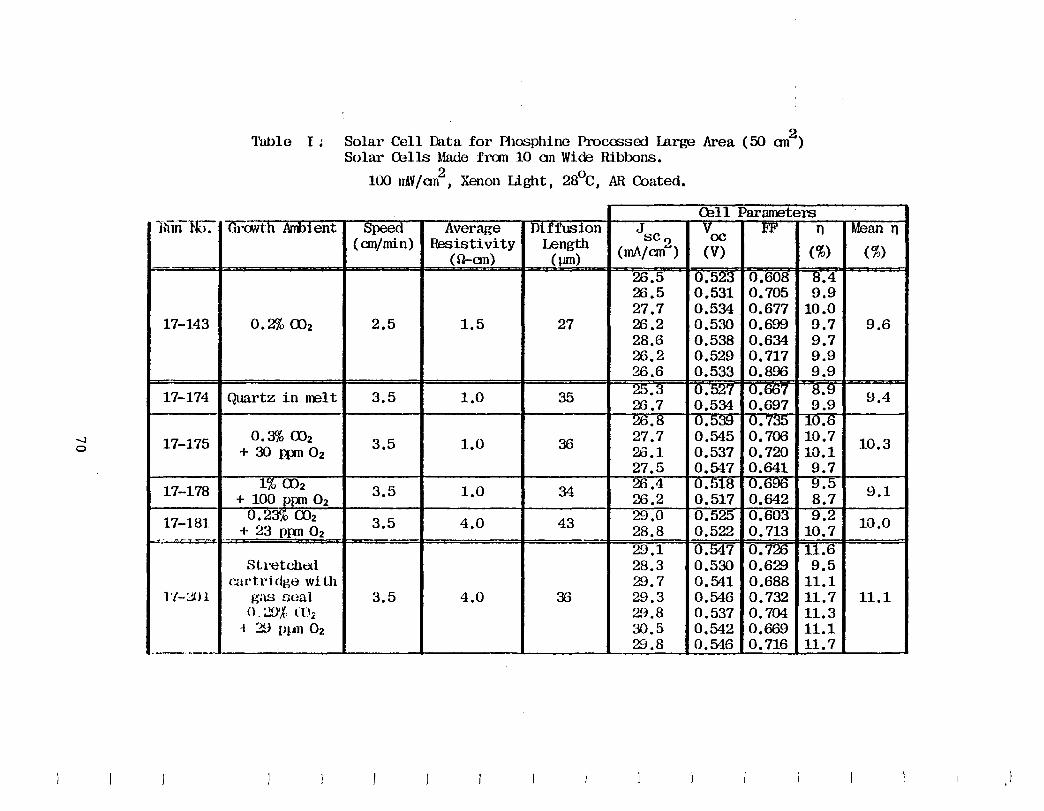
-...J o
Tullle I ~ Solar Cell Data for Fhosphine ProCffiSOO Large Area (50 an2 ) Solar Cells Made fran 10 an Wide Ribbons.
100 mV/an2
I Xenon Light I 28°C I AR Coated.
Cell Parameters lli"iil-Hc). -t1ro.vth ArID1 ent Speed Average Diffusion J Voc 1'1" n
(ern/min) Resistivity Length scI)
(O-an) ( lJIIl) (rnA/ern"') (V) (%)
26.5 0.523 0.608 8.4 28.5 0.531 0.705 9.9 27.7 0.534 0.677 10.0
17-143 0.2% Uh 2.5 1.5 27 26.2 0.530 0.699 9.7 28.6 0.538 0.634 9.7 26.2 0.529 0.717 9.9 26.6 0.533 0.896 9.9
17-174 Quartz in melt 3.5 1.0 35 25.~i 0.527 U.OO'( 8.9 26.7 0.534 0.697 9.9 26.ti U. b::f:} U.7;j!j 1U.o
17-1.75 0.3% 002 3.5 1.0 36 27.7 0.545 0.706 10.7 + 30 JlX11 02 26.1 0.537 0.720 10.1
27.5 0.547 0.641 9.7
1.7-178 1% 002 3.5 1.0 34 26.4 U.518 U.600 ~.5
+ 100 PIXTI O2 26.2 0.517 0.642 8.7
17-181 0.23% 002 3.5 4.0 43 29.0 0.525 0.603 9.2 + 23 Ppn 02 28.8 0.522 0.713 10.7 .. -~ -...
29.1 0.547 0.726 11.6 Stretched 28.3 0.530 0.629 9.5
cartri dge wi til 29.7 0.541 0.688 11.1 l'I-:,jJl gas Doal 3.5 4.0 36 29.3 0.546 0.732 11.7
0, :..!)'j. ({):< 29.8 0.537 0.704 11.3 -I 29 Pl.tn 02 30.5 0.542 0.669 11.1
29.8 0.546 0.716 11.7 .-,-... - ... ~ ..
Mean n (%)
9.6
9.4
10.3
9.1
10.0
11.1
At this program's conclusion, the demonstration of the technology readiness of the multiple ribbon furnace concept for EFG silicon ribbon remains incomplete. However, individual milestone achievements for ribbon growth performance in areas such as speed, thickness, cell efficiency and stress reduction in single ribbon furnaces indicate that the "1986 technology" goals of the FSA program are within reach for this EFG technology. Clearly, the rate of transfer of information crucial to the success of the multiple ribbon furnace concept from the single to the multiple ribbon furnace configuration has proven to be a limiting factor. In this aspect the program has lagged behind the rate of progress envisioned in the original plan for Mobil Tyco participation in the U.S. National Photovoltaic Program.
The tasks carried out in support of the development of this multiple ribbon furnace concept of EFG have produced significant new technology developments and fundamental research in areas not previously considered or explored for silicon ribbon production. In the early stages of the program, new techniques and engineering design elements were introduced to allow construction of resistance-heated furnaces in the belief these could ultimately be op~iated more efficiently than the conventional induction-heated furnaces. Graphite crucibles were introduced, both to explore their potential for reusability, and to eliminate system component degradation caused by oxygen in the form of SiO released from reaction of silicon and the conventional crucible material, silica. The latter was a particular problem in multiple ribbon furnaces because of their complexity and because of the desire to establish conditions favoring long-term operation without severe component degradation or loss. The peculiar problems associated with processing ribbon grown from graphite crucibles and their associated low oxygen environment were thoroughly explored. This led to the discovery that ribbon oxygenation via reactions of the meniscus melt and ambient gases such as CO and CO2 impacts ribbon quality and cell efficiency. It was demonstrated that the meniscus ambient could be used as an alternative means to quartz crucibles to provide the oxygen implicated in this phenomenon. Improvements in cell performance were realized with the introduction of displaced dies. These were shown to be capable of influencing ribbon subsurface structure and the SiC density, both of which were observed to appear more frequently in the normal resistance-heated furnace operating mode, and to produce more severe degradation of material quality and cell efficiency. than was experienced with induction-heating. In the growth a~ea, implementation of automatic controls of the ribbon width and melt replenishment demonstrated viability of growth of many ribbons at a time under the control of a single operator, as required ln the multiple ribbon format of this mode of EFG. Details of thesd ~nd other technology developments and research findings arg ccvered In depth in the reports, publications, and patents referenced at t~e end of this repor~ and in Appendix 7.
71
Shortfalls of the existing multiple ribbon furnace unit operated to the end of 1980 often had origins not anticipated from observation of growth in the single ribbon furnaces. A number of factors contributing to control of SiC generation were identified in the course of operation of the latter. One of these, the need to control concentrations of certain reactive gases, such as CO, in the meniscus environment, was of particular concern, and the technology developed for single ribbon growth was not immediately transferrable to the multiple ribbon unit. The multiplicity of openings of the latter was mainly responsible, and new techniques for total ambient control of the growth interface environment had to be developed for testing in a more complex format. In addition, the interaction of the main zone and cartridge temperature fields was observed to become a more significant parameter in the multiple ribbon furnace as ribbon width was increased. Special techniques were developed to allow modification of the multiple ribbon furnace main zone configuration to reduce nonuniformities in die top isotherms within individual cartridges which could not be compensated by the usual control element adjustments.
The reasons for the greater diversity of conditions encountered in multiple as compared to single ribbon furnace operating modes that hindered technology transfer appear to be quite complex. Foremost in consideration is an increase in the number of factors affecting a given interface environment in the multiple ribbon furnace. This has often made it more difficult to identify and separate out the influence of specific operational parameters and procedures on growth performance and on material quality that would have accelerated the multiple ribbon furnace development schedule. This difficulty to isolate the effects of parameters known to be of relevance has held up the technology readiness demonstrations perhaps more than any other single factor.
Whatever the impact of th~ increase in complexity of operating conditions may have been in retarding the multiple ribbon furnace development, certain more fundamental elements affect the longer term outlook for system performance potential and also deserve consideration. The most important of these are:
(1) The unavailability of growth system configurations that preserve the growth speed capability yet significantly reduce stress below levels presently produced during post-growth cooling. The manifestations of this have been noted above to be ribbon buckling and growth perturbations that affect throughput and ultimately reduce the yield of useful cell blanks; and to an increase in the density of defects that impact on and perhaps limit cell efficiency.
(2) The lack of flexibility in choice of growth conditions. This can impact both on material quality and on throughput and yield. The primary =ontributor to this situation appears to be
72
the relatively high value of h ff' the capillary rise height, that has resulted during system evo~U!ion to the design that is implicit in the cartridge concept. The higher h ff' the smaller is the range of "safe" operating conditions, or ~~niscus configurations. For the case of the crucial ribbon edge, the higher h ff reduces the maneuverability during growth initiation and the ~uDsequent ease of achieving predetermined, or most favorable growth conditions (meniscus height, ribbon thickness uniformity, and speed). This becomes more of an issue with increasing ribbon width. Special design concepts for cartridge components that control growth were specifically evolved to cope with this deficiency; these included profiled end and face heaters and cold shoes, special die designs and radiation shield configurations. These were introduced in the growth systems for wider ribbon in an attempt to preserve the die top isotherm uniformity needed to establish acceptable control and long-term stability. The success of this approach can be measured in the demonstration of growth durations without freezes in the five- to ten-hour range for 10 cm wide ribbon, and in the implementation of automatic width control systems that maintain ribbon width very precisely (± 1 mm) over these time spans without need for any operator intervention. Yet, these advances have not allowed definition of growth interface conditions that consistently lead to homogeneous ribbon of acceptable quality nor promote simplicity and consistency in operation. Rather, the acceptable "window" for control element settings that allow growth to be initiated reproducibly appears to have been narrowed with increasing ribbon width. In the final analysis, the simplest remedy for this, lowering of h f ' leads to negation of the original concept of the cartridge modij Ef operation, that of separation and decoupling of the main zone and growth interface environment.
(3) Shortfall in large area cell efficiency. Cell efficiency in cartridge systems has never approached the 12-14~ range demonstrated on the best EFG substrate available to date. At this time, the reasons for this shortfall and for a generally observed greater degree of inconsistency in material quality both in single and multiple ribbon furnace-grown ribbon cannot be attributed to specific causes. Rather, the suspicion is that the problem may be related to a lack of flexibility in growth condition selection and inconsistency in achieving reproducibly favorable (i.e., uniformly high meniscus) growth interface conditions. The chief contributing factor for this situation was discussed above in (2): the relatively large value of h ff characteristic of the cartridge mode of EFG. The manifestationeOt this i~ ~ generally greater degree of material inhomogeneity and a more frequent appearance of high concentrations of detrimental defects than found in the best EFG ribbon. Thus, average performance levels are consistently depressed even though individual smaller areas of material may have the required quali~y to produce 13% efficiency. The presence of a more severe post-growth temperature profile leading to generation of higher stresses because of the presence of the cold shoes used to enhance speed capability undoubtedly is a second
73
factor that contributes toward exacerbating this situation. Again, stress reduction becomes an important consideration in the quest for improvements in cell efficiency.
In summary, it is evident that a number of questions remain yet to be answered regarding the ultimate potential of the EFG technology which was developed in this program. Tight scheduling and funding decreases at critical junctures of the program are considered to be dominant factors in causing slippage in the 1980 interim Technical Features Demonstration. That these were crucial elements affecting the timing and success of the program was known at its conception, and reflected its high risk nature. As noted above, this situation was complicated by the need to develop new technology for silicon ribbon production that deviated significantly from equipment already in use at Mobil Tyco. This necessitated research in fundamentals of the growth process and material properties to overcome deficiencies not anticipated on the basis of known EFG system characteristics.
74
1. U.S. 4,188,197, "Cartridge and Furnace for Crystal Growth", Brian H. Mackintosh and David N. Jewett, October 3, 1978; U.S. 4,158,038, "Method and Apparatus for Reducing Residual Stress in Crystals", David N. Jewett, June 12, 1979.
2. A.D. Morrison, "Scale-Up of Program on Continuous Silicon Solar Cells", Final Report, NSF Grant GI43873, September 1975.
3. F.V. Wald et al., "Large Area Silicon Sheet by EFG" , Fourth Quarterly Progress Report, DOE/JPL 954355/77-4, Covering Period October 1, 1977 - December 31, 1977 (January 15, 1978 ) .
4. F.V. Wald et al., "Large Ar~a Silicon Sheet by EFG", First Quarterly Progress Report, DOE/JPL 954355/78-1, Covering Period January 1, 1978 - March 31, 1978 (April 15, 1978).
5. F.V. Wald et al., "Large Area Silicon Sheet by EFG", Annual Progress Report, ERDA/JPL 954355/77-3, Covering Period October 1, 1976 - September 30, 1977 (September 15, 1977).
6. F.V. Wald et et., "Large Area Silicon Sheet by EFG", Annual Progress Report, DOE/JPL 954355/78-3, Covering Period October 1, 1977 - September 30, 1978 (February 16, 1979).
7. F.V. Wald et al., "Large Area Silicon Sheet by EFG" , Second Quarterly Progress Report, DOE/JPL 954355/78-2, Covering Period April 1, 1978 - June 30, 1978 (July 15, 1978).
8. F.V. Wald et al., "Large Area Silicon Sheet by EFG" , Second Quarterly Progress Report, DOE/JPL 954355/80-2, Covering Period April 1, 1980 - June 30, 1980 (October 31, 1980).
9. J.P. Kalejs et al., "Large Area Silicon Sheet by EFG" , Fourth Quarterly Progress Report, DOE/JPL 954355/81-20, Covering Period October 1, 1981 - December 31, 1981 (February 22, 1982 ) .
10. F.V. Wald et al., "Large Area Silicon Sheet by EFG~, Second Quarterly Progress Report, DOE/JPL 954355/79-2, Covering Period April 1, 1979 - June 30, 1979 (July 15, 1979).
11. J.P. Kalejs et al., "Large Area Silicon Sheet by EFG", First Quarterly Progress Report, DOE/JPL 954355/81-17, Covering Period January 1, 1981 - March 31, 1981 (May 29, 1981).
12. A.D. Morrison et al., "Large Area Sheet by EFG" , Annual Progress Report, ERDA/JPL 954355/76-3, Covering Period October 29, 1975 - September 30, 1976 (September 15, 1976).
75

13. F. V. Wald et al., "Large Area Silicon Sheet by EFG", Annual Progress Report, DOE/JPL 954355/80-3, Covering Period October 1, 1979 - September 30, 1980 (February 2, 1981).
14. A.R. Mokachi and A.H. Kachare, "Sensitivity Analysis of the Add-On Price Estimate for the Edge-Defined Film-Fed Growth Process", LSA Project Report 5101-171, March 15, 1981.
76
All tasks on the program terminated on December 31, 1981.
Total cumulative man hours and cost plus fixed fee through December 31, 1981, are 123,335 and $4,596,276, respectively.
3. Engin~ing Dra~ing2 and ~~etches g~n~~~~g QY~ing ~h~ Re~.Qrting Pe~i.Qg
All drawings and sketches required were submitted to JPL at various times during the contract, when the delivery schedules called for them.
4. ~umms~ of Characterization Da~~ g~erateg Du~ing ~h~ B~~~ting £~~i.Qg
As in Sections I to V of the report and Appendix 7 below.
None.
All items of new technology have been reported to JPL.
Bibliography of publications and patents generated during the program.
77

Intentionally left Blank
r-I I
APPEtiDIX 1 ~ibliog~RhI of Pu~ll£atlQn~ gng Pa1ent~
g~nerated During 1h~ PrQg~gm
1. J.P. Kalejs, L.-Y. Chin and F.M. Carlson, "Interface Shape Studies for Silicon Ribbon Growth by the EFG Technique, Part I: Transport Phenomena Modeling", accepted for publication in the Journal of Crystal Growth.
2. J.P. Kalejs, "Interface Shape Studies for Silicon Ribbon Growth by the EFG Technique, Part II: Effect of Die Asymmetry", accepted for publication in the Journal of Crystal Growth.
3. J.P. Kalejs and L.-Y. Chin, "Modeling of Ambient-Meniscus Melt Interactions Associated with Carbon and Oxygen Transport in EFG of Silicon Ribbon", J. Electrochem. Soc., l~~ (1982) 1356.
4. C.T. Ho, "Photovoltaic Investigation of Minority Carrier Lifetime in the Heavily-Doped Emitter Layer of Silicon Junction Solar Cell", J. Appl. Phys. ~~ (1982) 507.
5. F.V. Wald, "Crystal Growth of Silicon Ribbons for Terrestrial Solar Cells by the EFG Method", in: Crystals: Growth, Properties and Applications 5 (Springer-Verlag Berlin Heidelberg 1981), pp. 149-198.
6. C.T. He and F.V. Wald, "Some Aspects of the Effect of Heat Treatment on the Minority Carrier Diffusion Length in Low Resistivity p-Type Silicon", phys. stat. sol.(a), §.1 (1981) 103.
7. C.T. Ho and J.D. Mathias, "Effect of Short Wavelength Illumination on the Characteristic Bulk Diffusion Length in Ribbon Silicon Solar Cells", Solid-State Electron., ~i (1980) 115.
8. B. Mackintosh, J.P. Kalejs, C.T. Ho and F.V. Wald, "Multiple EFG Silicon Ribbon Technology as the Basis for Manufacturing Low-Cost Terrestrial Solar Cells", in: 3rd E.C. Photovoltaic Solar Energy Conference, W. Palz, ed. (Dordrecht: D. Reidel; 1981), p. 553.
9. J.P. Kalejs, B.H. Mackintosh and T. Surek, "High Speed EFG of Wide Silicon Ribbon", J. Crystal Growth, ~Q (1980) 175.
79
10. C.V.H.N. Rao, M.C. Cretella, F.V. Wald and K.V. Ravi, "Imperfections and Impurities in EFG Silicon Ribbons", J. Crystal Growth, ~Q (1980) 311.
11. E.M. Sachs, "Thermal Sensitivity and Stability of EFG Silicon Ribbon Growth", J. Crystal Growth, ~Q (1980) 102.
12. E.M. Sachs and T. Surek, "Dynamics and Control of Meniscus Height in Ribbon Growth by the EFG Method", J. Crystal Growth, ~Q (1980) 114.
13. J.P. Kalejs, M.C. Cretella, F.V. Wald, and B. Chalmers, "Effects of Ambient Gas Changes During Growth on the Properties of EFG Silicon Ribbon", in: Proc. of Symposia on Electronic and Optical Properties of Polycrystalline or Impure Semiconductors and Novel Silicon Growth Methods, ed. K.V. Ravi and B. O'Mara (Princeton: The Electrochemical Society; 1980), p. 242.
14. J.P. Kalejs, B.H. Mackintosh, E.M. Sachs and F.V. Wald, "Progress in the Growth of Wide Silicon Ribbons by the EFG Technique at High Speeds Using Multiple Growth Stations", 14th IEEE Photovoltaic Specialists Conference Record (New York: IEEE: 1980), p. 13.
15. J.P. Kalejs, G.M. Freedman and F.V. Wald, "Aluminum Redistribution in EFG of Silicon Ribbon", J. Crystal Growth, 1.~ (1980) 74.
16. E.M. Sachs, "In-Situ Carbon-Silicon Ribbon Thermocouple", J. Crystal Growth, 12 (1979) 477.
17. B.H. Mackintosh, T. Surek, J.P. Kalejs, E.M. Sachs, S. Nagy and F.V. Wald, "Multiple Silicon Ribbon Growth by EFG" , 13th IEEE Photovoltaic Specialists Conference Record (New York: IEEE; 1978), p. 350.
18. C.V. Hari Rao, R.O. Bell, M.C. Cretella, J.C. Ho, F.V. Wald and K.V. Ravi, "Response of Defects to Illumination in Silicon Solar Cells", 13th IEEE Photovoltaic Specialists Conference Record (New York: IEEE; 1979), p. 1213.
19. J.P. Kalejs, "Impurity Redistribution in EFG", J. Crystal Growth, 1.1. (1978) 329.
20. C.V. Hari Rao, T. Surek, B. Mackintosh, K.V. Ravi and F.V. Wald, "Large Area Silicon Sheet by EFG", in: Sun: Mankind's Future Source of Energy, ed. F. deWinter (Pergamon: New York; 1978), p. 643.
21. Douglas Yates, "A CCD-Based Control Syst~m for Crystal Growth", Proceedings of the Soc:~ty of Photo-Optical Instrumentation Engineers, 112. (1077) 92.
22. T. Surek. C.V. Hari Rao, J.C. Swartz. and L.C. Garone, "Surface Morphology and Shape Stability in Silicon Ribbons Grown by the Edge-Defined, Film-Fed Growth Process", J. Electrochem. Soc., 124 (1977) 112.
23. L.C. Garone, C.V. Hari Rao, A.D. Morrison, T. Surek, and K.V. Ravi, "Orientation Dependence of Defect Structure in EFG Silicon Ribbons", Appl. Phys. Lett., ~2 (1976) 511.
24. Additional material on silicon ribbon EFG and other shaped crystal growth is referenced in: Dorothy O. Bergin, "Shaped Crystal Growth - A Selected Bibliography", J. Crystal Growth, SO (1980) 381.
U.S. 4.239,583 "Method and Apparatus for Crystal Growth Control", Arthur E. Hatch and Douglas A. Yates, December 16. 1980.
U.S. 4.242.589 "Apparatus for Monitoring Crystal Growth", E.M. Sachs, December 30, 1980.
U.S. 4,277,441 "Apparatus for Monitoring Crystal Growth", E.M. Sachs. July 7, 1981.
U.S. 4,319.769 "Apparatus and Method for Monitoring Crystal Growth", E.M. Sachs, March 9, 1992.
U.S. 4,335,091 "Crystal Growth Furnace with Trap Doors", Brian H. Mackintosh, June 15, 1992.
MTA-29
MTA-29 Div.
MTA-34 CIP
MTA-41
J. Kalejs et al., "Displaced Capillary Dies".
J. Kalejs et al., "Displaced Capillary Dies".
F. Wald et al., "Control of Atmosphere Surrounding Crystal Growth Zone".
J. Kalejs, "Method and Apparatus for Controlling the Atmosphere Surrounding a Crystal Growth Zone".
81

End o1f Document