Embed Size (px)
Citation preview
’99- ’05 Chevy Truck Instruction Manual
Copyright 2005
Squires Turbo Systems, Inc.
IC
'99-'05 Chevy Truck
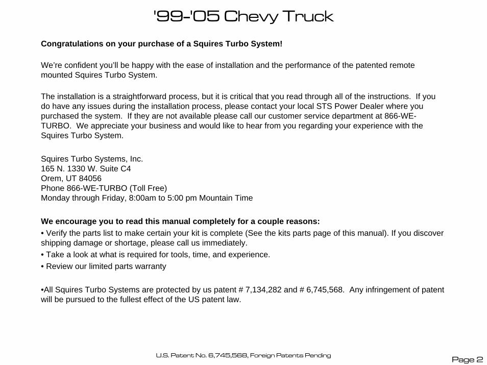
Congratulations on your purchase of a Squires Turbo System!
We’re confident you’ll be happy with the ease of installation and the performance of the patented remote mounted Squires Turbo System.
The installation is a straightforward process, but it is critical that you read through all of the instructions. If you do have any issues during the installation process, please contact your local STS Power Dealer where you purchased the system. If they are not available please call our customer service department at 866-WE-TURBO. We appreciate your business and would like to hear from you regarding your experience with the Squires Turbo System.
Squires Turbo Systems, Inc.165 N. 1330 W. Suite C4Orem, UT 84056Phone 866-WE-TURBO (Toll Free)Monday through Friday, 8:00am to 5:00 pm Mountain Time
We encourage you to read this manual completely for a couple reasons:• Verify the parts list to make certain your kit is complete (See the kits parts page of this manual). If you discover shipping damage or shortage, please call us immediately.• Take a look at what is required for tools, time, and experience.• Review our limited parts warranty
•All Squires Turbo Systems are protected by us patent # 7,134,282 and # 6,745,568. Any infringement of patent will be pursued to the fullest effect of the US patent law.
U.S. Patent No. 6,745,568, Foreign Patents Pending Page 2
'99-'05 Chevy Truck
IMPORTANT: It is the responsibility of the owner of the turbo system to make any necessary upgrades to the vehicle’s fuel system, engine and drive-train components, etc to ensure optimal performance and reliability and to prevent damage to engine and drive-train components. By installing this turbocharger system, the owner understands and acknowledges the severity of the vehicle damage that may occur by turbo charging an improperly modified and tuned vehicle and accepts all risk and responsibility.
Our systems are designed for stock engines, with stock components, in good mechanical condition only. Installation on worn or damaged engines is not recommended and may result in engine failure, for which we cannot be held responsible . Squires Turbo Systems, Inc. is not responsible for the engine or consequential damages. By proceeding with this install you accept full responsibility for any damage that may occur.
It is also the responsibility of the owner to comply with all emissions laws in their state. At this point your Squires Turbo System does NOT have a CARB EO number and is for Off-road use only in California.
Before you drive your vehicle we recommend:• Your vehicle be in good running condition• Change your fuel filter• Tune-up with spark plugs gapped to .035”.• 91 or higher octane fuel in the tank• Proper tuning• Install a boost gauge and test boost levels @ 5-6 psi• Test air/fuel ratios using a wideband O2 gauge (11.5:1 recommended)• Use caution until you are familiar with the system
Please remember to follow all safety rules that apply when working, including:• Wear eye protection• Do not work on a hot engine• Keep sparks and flames away from your work area - fuel is highly flammable
Page 3
'99-'05 Chevy Truck Kit Parts
Diagram 1
1
2
3
7
8
6
5
4 9
10
11
12
13
14 15
16
17
18
19 20
21
22
23
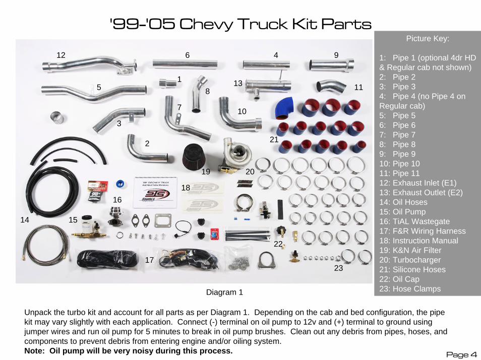
Picture Key:
1: Pipe 1 (optional 4dr HD & Regular cab not shown)2: Pipe 23: Pipe 34: Pipe 4 (no Pipe 4 on Regular cab)5: Pipe 56: Pipe 67: Pipe 78: Pipe 89: Pipe 910: Pipe 1011: Pipe 1112: Exhaust Inlet (E1)13: Exhaust Outlet (E2)14: Oil Hoses15: Oil Pump16: TiAL Wastegate17: F&R Wiring Harness18: Instruction Manual19: K&N Air Filter20: Turbocharger21: Silicone Hoses22: Oil Cap23: Hose Clamps
Page 4
Unpack the turbo kit and account for all parts as per Diagram 1. Depending on the cab and bed configuration, the pipe kit may vary slightly with each application. Connect (-) terminal on oil pump to 12v and (+) terminal to ground using jumper wires and run oil pump for 5 minutes to break in oil pump brushes. Clean out any debris from pipes, hoses, and components to prevent debris from entering engine and/or oiling system. Note: Oil pump will be very noisy during this process.
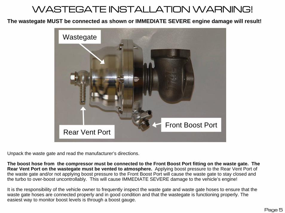
WASTEGATE INSTALLATION WARNING!The wastegate MUST be connected as shown or IMMEDIATE SEVERE engine damage will result!
Wastegate
Front Boost PortRear Vent Port
Unpack the waste gate and read the manufacturer’s directions.
The boost hose from the compressor must be connected to the Front Boost Port fitting on the waste gate. The Rear Vent Port on the wastegate must be vented to atmosphere. Applying boost pressure to the Rear Vent Port of the waste gate and/or not applying boost pressure to the Front Boost Port will cause the waste gate to stay closed and the turbo to over-boost uncontrollably. This will cause IMMEDIATE SEVERE damage to the vehicle’s engine!
It is the responsibility of the vehicle owner to frequently inspect the waste gate and waste gate hoses to ensure that the waste gate hoses are connected properly and in good condition and that the wastegate is functioning properly. The easiest way to monitor boost levels is through a boost gauge.
Page 5
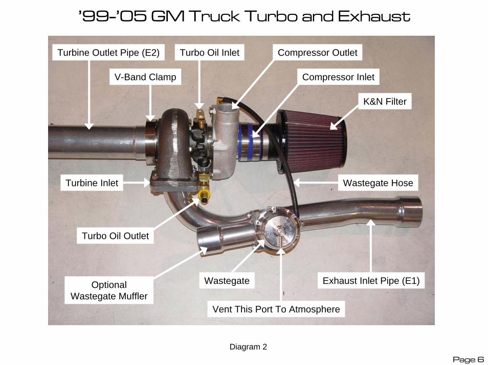
’99-’05 GM Truck Turbo and Exhaust
Turbine Inlet
Turbine Outlet Pipe (E2)
Compressor Inlet
Wastegate
Compressor Outlet
Vent This Port To Atmosphere
V-Band Clamp
Turbo Oil Outlet
Exhaust Inlet Pipe (E1)
Wastegate Hose
Turbo Oil Inlet
Optional Wastegate Muffler
K&N Filter
Diagram 2Page 6
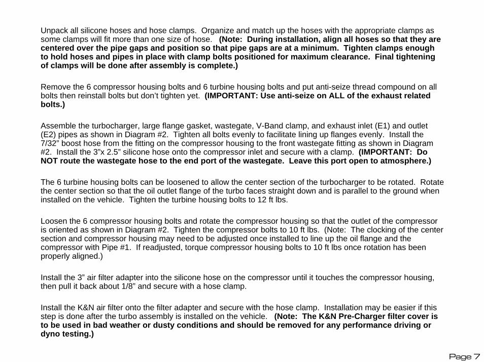
Unpack all silicone hoses and hose clamps. Organize and match up the hoses with the appropriate clamps as some clamps will fit more than one size of hose. (Note: During installation, align all hoses so that they are centered over the pipe gaps and position so that pipe gaps are at a minimum. Tighten clamps enough to hold hoses and pipes in place with clamp bolts positioned for maximum clearance. Final tightening of clamps will be done after assembly is complete.)
Remove the 6 compressor housing bolts and 6 turbine housing bolts and put anti-seize thread compound on all bolts then reinstall bolts but don’t tighten yet. (IMPORTANT: Use anti-seize on ALL of the exhaust related bolts.)
Assemble the turbocharger, large flange gasket, wastegate, V-Band clamp, and exhaust inlet (E1) and outlet (E2) pipes as shown in Diagram #2. Tighten all bolts evenly to facilitate lining up flanges evenly. Install the 7/32” boost hose from the fitting on the compressor housing to the front wastegate fitting as shown in Diagram #2. Install the 3”x 2.5” silicone hose onto the compressor inlet and secure with a clamp. (IMPORTANT: Do NOT route the wastegate hose to the end port of the wastegate. Leave this port open to atmosphere.)
The 6 turbine housing bolts can be loosened to allow the center section of the turbocharger to be rotated. Rotate the center section so that the oil outlet flange of the turbo faces straight down and is parallel to the ground when installed on the vehicle. Tighten the turbine housing bolts to 12 ft lbs.
Loosen the 6 compressor housing bolts and rotate the compressor housing so that the outlet of the compressor is oriented as shown in Diagram #2. Tighten the compressor bolts to 10 ft lbs. (Note: The clocking of the center section and compressor housing may need to be adjusted once installed to line up the oil flange and the compressor with Pipe #1. If readjusted, torque compressor housing bolts to 10 ft lbs once rotation has been properly aligned.)
Install the 3” air filter adapter into the silicone hose on the compressor until it touches the compressor housing, then pull it back about 1/8” and secure with a hose clamp.
Install the K&N air filter onto the filter adapter and secure with the hose clamp. Installation may be easier if this step is done after the turbo assembly is installed on the vehicle. (Note: The K&N Pre-Charger filter cover is to be used in bad weather or dusty conditions and should be removed for any performance driving or dyno testing.)
Page 7
’99-’05 GM Truck Electrical Connections
Power Distribution Box
Support Bracket
Main Relay
Firewall Grommet
STS Harness
Factory Ground (-) Terminal
Inline Fuse Holder
Remote Battery (+) Terminal
Diagram 3
Page 8
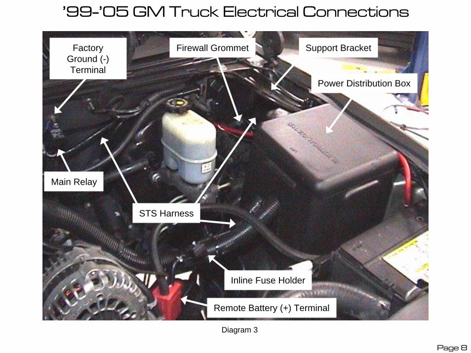
Connect and route the front wiring harness to the following terminals as shown in Diagram #3, leaving the fuse out of the harness at this time.
Connect the RED fused lead to the remote battery (+) terminal as shown.
Route the harness along the factory loom going to the Power Distribution Box and over to the LR of the engine compartment then over the brake booster and along the firewall.
Remove the nut on the factory ground strap terminal on the firewall and secure the BLACK ground wire to this terminal with the factory nut then secure the Main Relay with the 6mm nut provided as shown.
Route the remaining section of the front harness along the firewall to the passenger side of the engine compartment.
Make a small hole and route the section of the harness with the BLUE and WHITE wires and the Phone Jack through the firewall grommet and inside the vehicle. From inside the vehicle, plug the Buzzer into the Phone Jack and secure under the dash. Wrap the Phone Jack connector with electrical tape to prevent accidental disconnection. Route the HIGH/LOW oil pump speed bypass switch through the firewall and secure under the dash.
(Note: This switch will bypass the automatic LOW/HIGH speed operation of the oil pump and run the oil pump on HIGH speed only for racing and/or cold weather conditions.)
Page 9
'99-'05 GM Truck Fuel Pump Power Supply
Power Distribution Block At Driver’s Side Of Engine
Compartment
Connect Blue STS Harness Wire To T-Tap
Connector
Fuel Pump Wire – Grey 14 Gauge
Diagram 4Page 10
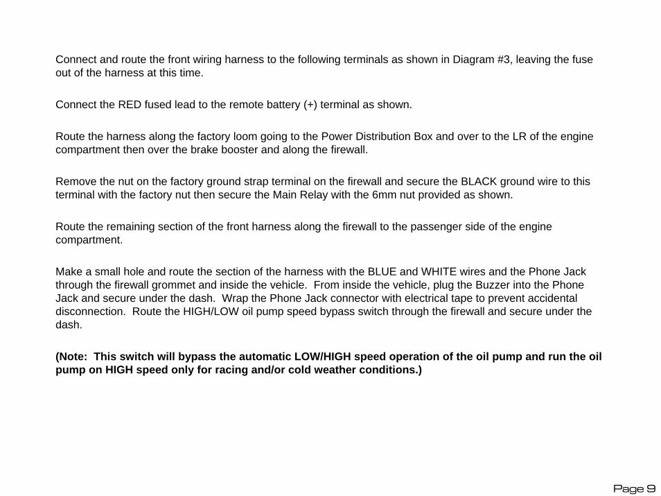
Remove the cover for the Power Distribution Block located in the engine bay next to the LH front fender. Remove the support bracket (shown in Diagram #3) from the fender to the firewall and remove the plastic housing to access the wires.
Locate the fuel pump power wire coming from the fuel pump relay as shown in Diagram #4. Install the provided T-Tap connector onto the 14 gauge GREY wire as shown.
(IMPORTANT: Test this wire as there may be more than one wire of the same size and color! This wire will test +12v for approximately 2 seconds when the ignition is cycled to the “ON” position with the engine not running, after 2 seconds the circuit will read “OPEN”. Make sure that the MAF sensor is plugged in to prevent setting a PCM trouble code.)
Route the remaining lead on the wiring harness containing the single BLUE wire to the fuel pump wire and connect the male spade terminal into the T-Tap connector. Reinstall the covers and support bracket.
(IMPORTANT: T-Tap connectors can become loose and develop poor connections if they get pulled on after installation. It is recommended that this connection be soldered for increased durability.)
Page 11
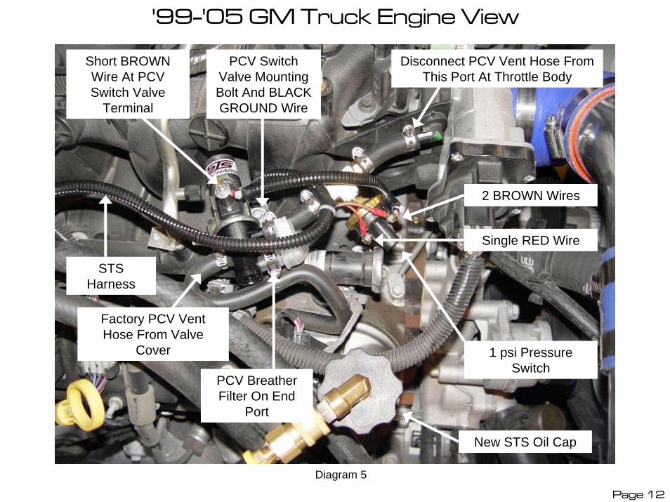
'99-'05 GM Truck Engine View
Factory PCV Vent Hose From Valve
Cover
Short BROWN Wire At PCV Switch Valve
Terminal
Disconnect PCV Vent Hose From This Port At Throttle Body
1 psi Pressure Switch
PCV Switch Valve Mounting Bolt And BLACK GROUND Wire
PCV Breather Filter On End
Port
New STS Oil Cap
STS Harness
2 BROWN Wires
Single RED Wire
Diagram 5
Page 12
Disconnect the electrical connector from the Mass Air Flow Sensor (MAF) and remove the MAF sensor from the intake ducting and remove the upper and lower pieces of the factory air box and the intake ducting to the throttle body.
Remove the plastic intake manifold cover(s) and disconnect the factory PCV vent hose from the port on the throttle body.
(Note: Some models may use a PCV Orifice instead of a PCV Valve, a PCV Valve or a Check-Valve must be installed on vehicles with a PCV Orifice to prevent boost from pressurizing the crank case.)
Loosely mount the PCV Switch Valve to the plastic intake manifold with the supplied bolt as shown and connect the 1 psi pressure switch to the port next to the metal body on the solenoid (on the dual port side of the switch valve) and to the port at the throttle body with the hoses provided and secure with clamps as shown in Diagram #5.
Route the STS wiring harness along the intake manifold and install the BLACK ground wire onto the PCV Switch Valve mounting bolt and secure the switch valve and the ground wire to the plastic intake manifold as shown.
(Note: Do NOT bolt this wire to an engine ground. This BLACK ground wire provides the ground for the switch valve body, as it is bolted into a plastic manifold with no ground.)
Connect the RED wire from the STS harness to one terminal on the pressure switch. Connect the BROWN wire from the harness and one end of the short BROWN wire extension to the other terminal on the pressure switch then connect the other end of the short BROWN wire extension to the single terminal on the PCV Switch Valve.
Remove the factory oil cap and replace with the new oil cap. Install the 3/8” oil return hose onto the hose barb on the quick disconnect fitting at the oil cap, connect the fitting to the cap and route this hose down along the RH frame rail and under the vehicle avoiding any Hot, Sharp and/or Moving objects.
(Note: This hose barb is a “Push-Lock” type fitting which is difficult to install but doesn’t require a hose clamp once installed.)
Page 13
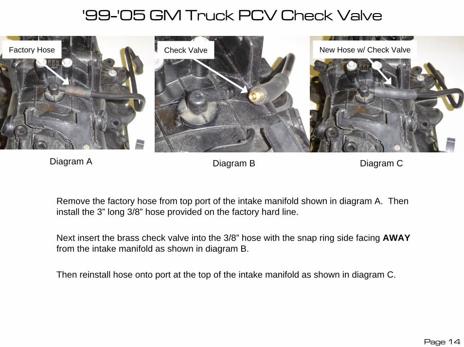
'99-'05 GM Truck PCV Check Valve
Diagram CDiagram BDiagram A
Remove the factory hose from top port of the intake manifold shown in diagram A. Then install the 3” long 3/8” hose provided on the factory hard line.
Next insert the brass check valve into the 3/8” hose with the snap ring side facing AWAYfrom the intake manifold as shown in diagram B.
Then reinstall hose onto port at the top of the intake manifold as shown in diagram C.
New Hose w/ Check ValveCheck ValveFactory Hose
Page 14

Intentionally Left Blank
Page 15Page 25
'99-'05 GM Truck Pipe 10, 11 and T-Body
Inline Resistor
Main Relay And GroundSecondary Relay
MAF Sensor
Pipe #10 Pipe #11
T-Body Elbow
Oil Return Hose
Diagram 6 Page 16
Page 17
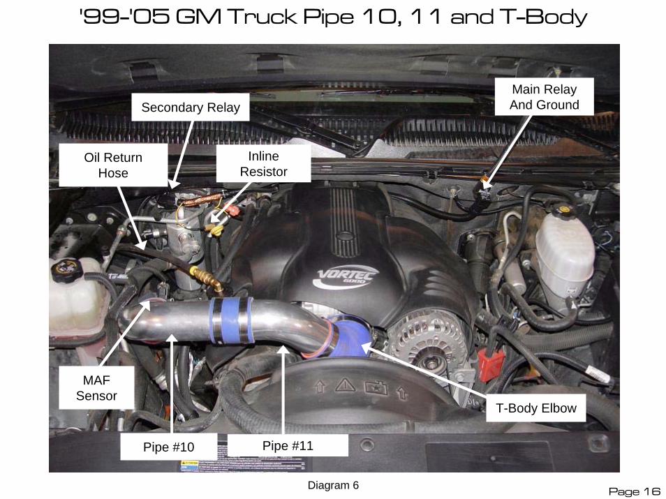
Secure the secondary relay to the factory wiring harness with a nylon tie leaving the harness connector in the RR of the engine compartment near the firewall as shown in Diagram #6. Secure the entire front wiring harness with nylon ties making sure that the harness is protected from all Hot, Sharp and/or Moving parts and that the inline resistor is positioned to give adequate clearance from objects which could be damaged by heat.
(WARNING: The inline resistor in the STS wiring harness gets VERY HOT! DO NOT TOUCH the resistor after the vehicle has been running as it will cause SEVERE BURNS! Make sure that the inline resistor in the harness is kept away from the harness and away from any parts or equipment that could be damaged from the heat that the resistor produces. Make sure that the resistor hangs free and there is no ‘tension’ on the wires connected to the resistor.)
(Note: If an optional intercooler is to be installed, refer to the intercooler installation instructions before proceeding, as the intake pipe routing will be different with the intercooler option.)
Install the silicone elbow onto the throttle body with 2 clamps and secure the elbow to the T-Body with one clamp. Insert Pipe #11 into the throttle body elbow and secure the other hose clamp to hold Pipe #11 in position as shown in Diagram #6.
Install a 3” silicone hose and 2 hose clamps onto the outlet end of Pipe #10 and a 3.75” silicone hose onto the inlet of Pipe #10 as shown and secure the clamps. Insert the outlet end of Pipe #10 into Pipe #11 and secure the clamp.
Install a 3.75” silicone hose and 2 clamps onto the INLET end of the MAF sensor (according to the flow direction arrow cast into the side of the MAF sensor) and secure with a clamp. Install the outlet end of the MAF sensor into the inlet of Pipe #10 and secure the clamp.
(Note: Rotate the MAF sensor to provide maximum clearance of wiring harness from the exhaust manifold.)
Install a 3” silicone hose and clamps onto the inlet end of Pipe #9 and secure the hose clamp then slide Pipe #9 down along the inner fender-well and insert the large end of Pipe #9 into the inlet end of the MAF sensor and tighten the clamp then plug in the MAF sensor connector. Make sure that the pipes line up straight and the hoses are centered over pipe gaps.
If installing a Blow Off Valve continue onto next page.
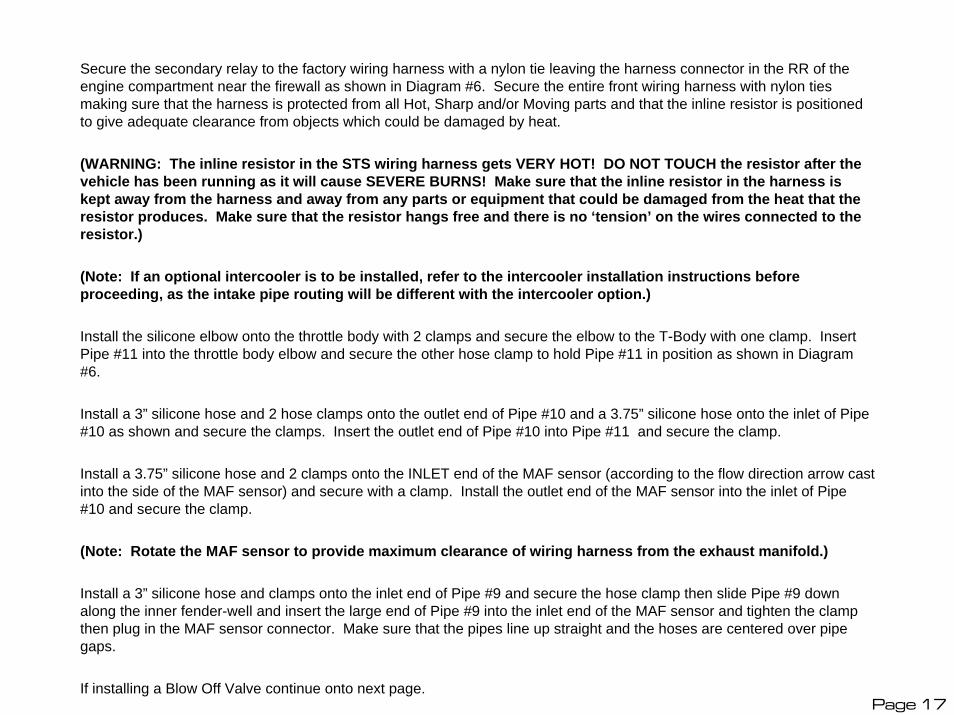
GM TRUCK NON-INTERCOOLED BLOW OFF VALVE INSTALLATION
¼” HOSE TO BOV
Mass Air Flow Sensor T FITTING
Check Valve At Brake Booster
Page 18

GM TRUCK NON-INTERCOOLED BLOW OFF VALVE INSTALLATION
Install the Blow Off Valve onto pipe #9 with the band clamp as shown above making sure that the O-Ring is positioned correctly. Install the BOV port fitting with one gasket on each side of the banjo fitting. Remove the factory vacuum hose from the check valve at the brake booster. Insert the supplied T-fitting into the factory hose and secure with the factory clamp as shown. Install the supplied 2” hose onto the T-fitting and connect to the factory vacuum port on the brake booster check valve and secure with clamps. Install the 40” hose onto the remaining T fitting and route the hose over to the blow off valve and cut to length, keeping length as short as possible. Make sure that the hose is routed away from sharp and/or hot objects. Secure the hose onto the T-fitting and the BOV port with the hose clamps provided.
(Note: For high altitude applications a lighter (9#) spring is available to quicken valve response with low vacuum engines.)
Page 19

'99-'05 GM Truck Pipe 5-6 Mounting
RH Frame Rail
Center body mount
Pipe #5
Pipe #6Pipe #4
Pipe #7
Oil Hoses And Rear Wiring Harness
Diagram 7Page 20

Remove the 3 body mount bolts on RH side of cab. Using floor jack, raise RH side of truck under middle of RH frame rail then using a suitable jack-stand to support the RH side of the body, lower the frame to carefully lift the body off of the frame several inches.
(IMPORTANT: Always use appropriate jack stands or vehicle support equipment to prevent personal injury!)
This will allow you to position Pipe #5 inside the lip of the body near the middle body mount as shown in Diagram #7. It is helpful to remove the upper and lower middle rubber body mount to allow easier installation of Pipe #5. Once Pipe #5 is in position, reinstall the rubber mounts and raise the jack to lower the body back onto the mounts then secure Pipe #5 to the middle mount using factory bolt and supplied washer if needed.
(Note: If truck is equipped with a body lift, raising the body off the mounts may not be necessary as the intake pipes will sit under the body.)
Install a 2.5” x 3” silicone hose and 2 clamps onto the outlet end of Pipe #5 and secure the hose with the clamp.
Install a 2.5” x 3” silicone hose and 2 clamps onto the outlet end of Pipe #6 and install Pipe #6 into the outlet end of Pipe #5 and secure the hose clamps. Lower the vehicle.
(Note: For Regular Cab trucks, Pipe #5 will be shorter on the inlet end than on other models. Regular Cab trucks also DO NOT use a Pipe #4. Pipe #3 will connect directly to Pipe #5.)
Page 21
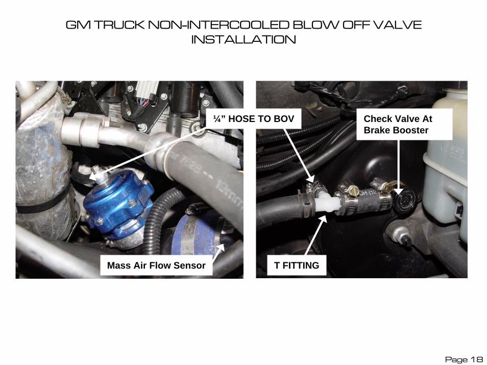
’99-’05 GM Truck Pipe 6-9
Pipe #7Pipe #9
Pipe #6
Front Body Mount
Stainless Oil Supply Hose, Rear Wiring
Harness and Oil Return Hose Pipe #8
Aftermarket Running
Board Mount
Diagram 8Page 22
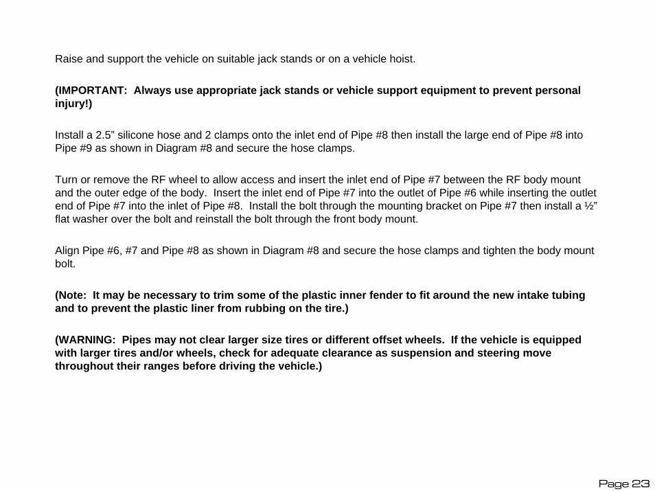
Raise and support the vehicle on suitable jack stands or on a vehicle hoist.
(IMPORTANT: Always use appropriate jack stands or vehicle support equipment to prevent personal injury!)
Install a 2.5” silicone hose and 2 clamps onto the inlet end of Pipe #8 then install the large end of Pipe #8 into Pipe #9 as shown in Diagram #8 and secure the hose clamps.
Turn or remove the RF wheel to allow access and insert the inlet end of Pipe #7 between the RF body mount and the outer edge of the body. Insert the inlet end of Pipe #7 into the outlet of Pipe #6 while inserting the outlet end of Pipe #7 into the inlet of Pipe #8. Install the bolt through the mounting bracket on Pipe #7 then install a ½”flat washer over the bolt and reinstall the bolt through the front body mount.
Align Pipe #6, #7 and Pipe #8 as shown in Diagram #8 and secure the hose clamps and tighten the body mount bolt.
(Note: It may be necessary to trim some of the plastic inner fender to fit around the new intake tubing and to prevent the plastic liner from rubbing on the tire.)
(WARNING: Pipes may not clear larger size tires or different offset wheels. If the vehicle is equipped with larger tires and/or wheels, check for adequate clearance as suspension and steering move throughout their ranges before driving the vehicle.)
Page 23

GM Oil Supply With Oil Cooler Option
New Mounting Bolts
Oil Supply Adapter Flange
Rear Of Vehicle
Stainless Oil Supply Hose To Turbo
Diagram 9Page 24

For GM Trucks with Oil Cooler Option (shown): Remove the 2 factory oil cooler adapter mounting bolts from the oil filter housing. Clean the gasket surfaces and remove any foreign debris from the oil supply adapter plate. Install the new oil supply adapter plate with the new gasket toward the block as shown in Diagram #9. Install the new 6mm x 50mm bolts through the cooler adapter, factory gasket, new adapter plate and new gasket in that order. Tighten the new bolts. Connect the stainless hose to the brass fitting.
For GM Trucks without Oil Cooler Option (not shown): Remove the 2 factory block off plate mounting bolts from the oil filter housing. Clean the gasket surfaces and remove any foreign debris from the block off plate, adapter plate and oil filter housing. Install the new oil supply adapter plate with the new gasket supplied toward the block as shown. Install the new 6mm x 40mm bolts through the block off plate, factory gasket, new adapter plate and new gasket in that order. Tighten the new bolts. Connect the stainless hose to the brass fitting.
(Note: Vehicles without oil cooler option will have a block off plate (similar to picture but without oil lines attached to the plate. They will also have a factory gasket with an ‘OVAL’ hole. This factory gasket must be installed between the block off plate and the STS oil supply adapter plate. The supplied gasket with ‘two round holes’ must be installed between the adapter plate and the oil filter housing. If these gaskets are reversed, oil will leak between the block off plate and the oil supply adapter plate!)
(IMPORTANT: Clean out any debris before reinstalling. It is VERY IMPORTANT that oil port, fittings, and oil line be FLUSHED OUT to remove any debris before connecting the stainless oil line to the turbocharger or SEVERE DAMAGE to the turbocharger will occur! Any debris in the oiling system can also cause SEVERE DAMAGE to the engine!)
Connect the stainless hose to the AN fitting on the bottom of the oil supply adapter plate. Cover the open end of the hose with tape and route the hose under the oil pan and along the RH frame rail with the oil return hose back toward the rear of the vehicle.
(Note: Cover the open end of the hoses with tape to prevent debris from entering hoses during installation.)
Page 25

'99-'05 GM Truck Pipes 1-5
Pipe 2
Pipe 3 Mount Pipe 4 Pipe 5
Pipe 1
Optional Air Filter Snorkel
Wastegate Hose Connection
Optional Boost Controller Hose
Diagram 10
Page 26
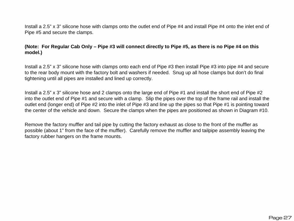
Install a 2.5” x 3” silicone hose with clamps onto the outlet end of Pipe #4 and install Pipe #4 onto the inlet end of Pipe #5 and secure the clamps.
(Note: For Regular Cab Only – Pipe #3 will connect directly to Pipe #5, as there is no Pipe #4 on this model.)
Install a 2.5” x 3” silicone hose with clamps onto each end of Pipe #3 then install Pipe #3 into pipe #4 and secure to the rear body mount with the factory bolt and washers if needed. Snug up all hose clamps but don’t do final tightening until all pipes are installed and lined up correctly.
Install a 2.5” x 3” silicone hose and 2 clamps onto the large end of Pipe #1 and install the short end of Pipe #2 into the outlet end of Pipe #1 and secure with a clamp. Slip the pipes over the top of the frame rail and install the outlet end (longer end) of Pipe #2 into the inlet of Pipe #3 and line up the pipes so that Pipe #1 is pointing toward the center of the vehicle and down. Secure the clamps when the pipes are positioned as shown in Diagram #10.
Remove the factory muffler and tail pipe by cutting the factory exhaust as close to the front of the muffler as possible (about 1” from the face of the muffler). Carefully remove the muffler and tailpipe assembly leaving the factory rubber hangers on the frame mounts.
Page 27

’99-’05 GM Truck Oil Pump
Oil Pump Outlet Oil Pump Inlet
BLACK and WHITE Harness Wires
BLACK WireYELLOW Wire
Oil PumpBLACK Harness Ground Wire Oil Return Hose
From Turbo
Oil Pump MountingBracket
Oil Return Hose To Valve Cover
Diagram 11
Page 28
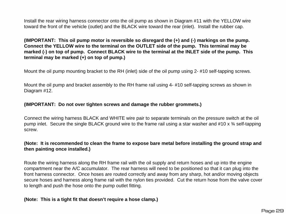
Install the rear wiring harness connector onto the oil pump as shown in Diagram #11 with the YELLOW wire toward the front of the vehicle (outlet) and the BLACK wire toward the rear (inlet). Install the rubber cap.
(IMPORTANT: This oil pump motor is reversible so disregard the (+) and (-) markings on the pump. Connect the YELLOW wire to the terminal on the OUTLET side of the pump. This terminal may be marked (-) on top of pump. Connect BLACK wire to the terminal at the INLET side of the pump. This terminal may be marked (+) on top of pump.)
Mount the oil pump mounting bracket to the RH (inlet) side of the oil pump using 2- #10 self-tapping screws.
Mount the oil pump and bracket assembly to the RH frame rail using 4- #10 self-tapping screws as shown in Diagram #12.
(IMPORTANT: Do not over tighten screws and damage the rubber grommets.)
Connect the wiring harness BLACK and WHITE wire pair to separate terminals on the pressure switch at the oil pump inlet. Secure the single BLACK ground wire to the frame rail using a star washer and #10 x ¾ self-tapping screw.
(Note: It is recommended to clean the frame to expose bare metal before installing the ground strap and then painting once installed.)
Route the wiring harness along the RH frame rail with the oil supply and return hoses and up into the engine compartment near the A/C accumulator. The rear harness will need to be positioned so that it can plug into the front harness connector. Once hoses are routed correctly and away from any sharp, hot and/or moving objects secure hoses and harness along frame rail with the nylon ties provided. Cut the return hose from the valve cover to length and push the hose onto the pump outlet fitting.
(Note: This is a tight fit that doesn’t require a hose clamp.)
Page 29

'99-'05 GM Truck Y-Pipe
Supplied Exhaust Clamps
Optional Factory 3” Dual Exhaust STS Y-Pipe
Turbine Inlet Pipe (E1)
Factory Exhaust Mount
Diagram 12
Page 30
Dual Exhaust 6.0L and 8.1L Option
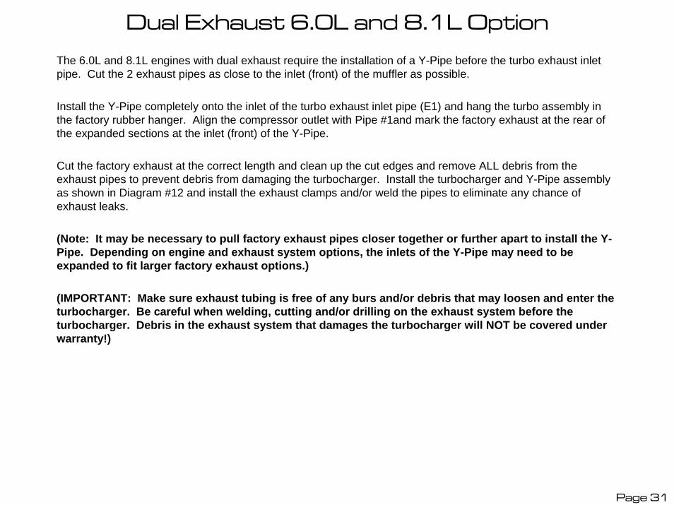
The 6.0L and 8.1L engines with dual exhaust require the installation of a Y-Pipe before the turbo exhaust inlet pipe. Cut the 2 exhaust pipes as close to the inlet (front) of the muffler as possible.
Install the Y-Pipe completely onto the inlet of the turbo exhaust inlet pipe (E1) and hang the turbo assembly in the factory rubber hanger. Align the compressor outlet with Pipe #1and mark the factory exhaust at the rear of the expanded sections at the inlet (front) of the Y-Pipe.
Cut the factory exhaust at the correct length and clean up the cut edges and remove ALL debris from the exhaust pipes to prevent debris from damaging the turbocharger. Install the turbocharger and Y-Pipe assembly as shown in Diagram #12 and install the exhaust clamps and/or weld the pipes to eliminate any chance of exhaust leaks.
(Note: It may be necessary to pull factory exhaust pipes closer together or further apart to install the Y-Pipe. Depending on engine and exhaust system options, the inlets of the Y-Pipe may need to be expanded to fit larger factory exhaust options.)
(IMPORTANT: Make sure exhaust tubing is free of any burs and/or debris that may loosen and enter the turbocharger. Be careful when welding, cutting and/or drilling on the exhaust system before the turbocharger. Debris in the exhaust system that damages the turbocharger will NOT be covered under warranty!)
Page 31

'99-'05 Chevy Truck Turbo Assembly
Exhaust Clamp
Factory Rubber Exhaust Mount
Oil Return Hose
6 Turbine Housing Bolts
Oil Outlet Flange Facing Straight DownWastegate Hose
Optional Air Filter Snorkel Hose
Diagram 13
Page 32

Install the turbo assembly as shown in Diagram #13 by inserting the hanger into the factory rubber mount and sliding the exhaust inlet pipe over the factory exhaust pipe (or Y-Pipe) and securing with the exhaust clamp provided. Install a 2” x 3” silicone hose and 2 clamps onto the compressor outlet and insert Pipe #1 into the compressor outlet. Line up the pipes and position them so that there is adequate clearance from the frame and body to prevent rubbing and/or vibration. Route the stainless oil supply hose to the fitting at the top of the turbo.
(IMPORTANT: Make sure that the compressor housing outlet lines up with Pipe #1 and that the turbo assembly is rotated into the proper position before tightening down the exhaust clamp. It may be necessary to cut some additional material from the factory exhaust if the turbo assembly is too far back. Once the turbo and pipes are in proper position, it is recommended that the pipes be welded together to prevent any exhaust leaks. However, with proper tightening of exhaust clamp the system should be secure for driving. Make sure that the factory exhaust is cleaned of any burs and free of any debris before installing the turbo assembly as any debris in the exhaust pipes will cause SEVERE damage to the turbocharger and will NOT be covered under the warranty!)
(Note: It may be necessary to re-clock the center section of the turbocharger so that the oil outlet flange is facing straight down. It may also be necessary to rotate the compressor housing to facilitate lining up the outlet with Pipe #1. If adjustments are made at this time, retighten the turbine housing bolts to 12 ft/lbs and the compressor housing bolts to 10 ft/lbs torque.)
Cut the oil return hose to length and install onto the turbo oil outlet flange fitting and onto the oil pump inlet fitting and secure to the oil pump with the hose clamp provided.
(IMPORTANT: Make sure that the oil outlet flange faces straight down and that the oil return hose slopes from the turbo outlet down into the oil pump. The oil should flow smoothly out of the turbocharger and down into the inlet of the oil pump. Make sure that the oil return hose is routed properly to prevent any damage to the hose from the exhaust exiting the wastegate and/or from hot exhaust components!)
Page 33
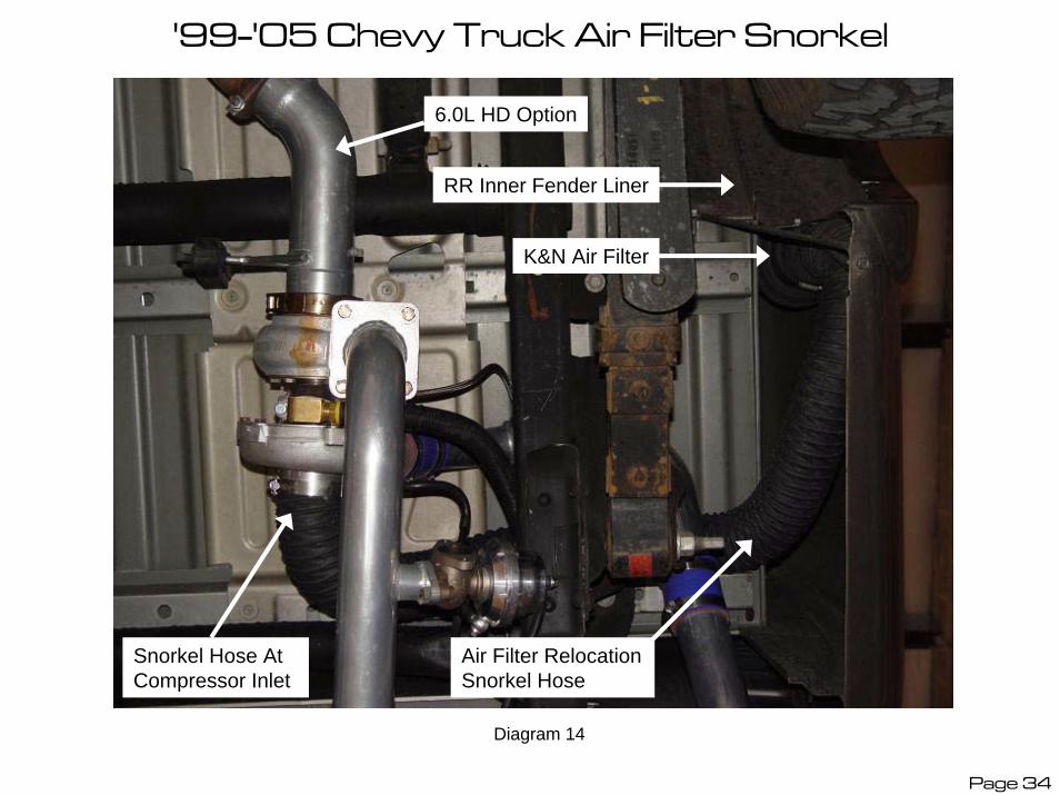
'99-'05 Chevy Truck Air Filter Snorkel
6.0L HD Option
K&N Air Filter
Air Filter Relocation Snorkel Hose
RR Inner Fender Liner
Snorkel Hose At Compressor Inlet
Diagram 14
Page 34

If installing the optional air filter relocation snorkel, remove the K&N air filter and the filter adapter and silicone hose from the inlet of the compressor housing. Install the snorkel hose onto the compressor inlet and secure with the hose clamp as shown in Diagram #14. Route the snorkel hose over the frame rail and up into the area between the inner and outer bed panels, just in front of the RR inner fender liner as shown.
Cut the snorkel hose to length. Insert the air filter adapter into the K&N air filter and secure with the hose clamp. Insert the air filter and adapter into the inlet end of the snorkel hose and secure with the hose clamp.
Install the air filter up into the bed side as shown and secure the hose in place with the large nylon ties provided.
(IMPORTANT: Make sure that the filter is located high enough in front of the RR inner fender liner to prevent any water and/or debris from being thrown off of the RR tire directly onto the air filter. Make sure that the snorkel hose is secure and routed properly to prevent accidental damage from any HOT, SHARP and/or MOVING objects.)
(Note: The air filter needs to be inspected and serviced regularly. If using the optional Dry-Charger filter cover, this cover needs to be cleaned more frequently than the air filter as it has less surface area. A dirty air filter and/or Pre-Charger will cause the turbocharger to pull vacuum at the inlet of the turbocharger which may cause oil to be pulled from the turbocharger and expelled into the intake tract. If this condition occurs, it is the responsibility of the vehicle operator to thoroughly clean out the intake tubing and MAF sensor. Oil contamination on the MAF sensor can cause drivability problems and or dangerously lean conditions which could cause SEVERE damage to the engine!)
(IMPORTANT: It is the responsibility of the vehicle operator to make sure that the air filter is never exposed to large amounts of water or driven through water that may submerge the air filter. Excessive water drawn into the air inlet system can cause IMMEDIATE SEVERE damage to the engine and will NOT be covered under the STS Warranty!)
Page 35
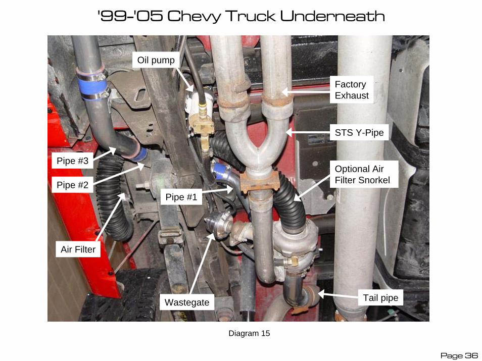
'99-'05 Chevy Truck Underneath
Wastegate
Air Filter
Pipe #2
Oil pump
Factory Exhaust
Pipe #1
Tail pipe
Optional Air Filter Snorkel
STS Y-Pipe
Pipe #3
Diagram 15
Page 36

Position all pipes to prevent rubbing on any components. Make sure that pipes are lined up as straight as possible and that pipe gaps are at a minimum. Make sure hoses are centered over gaps then tighten all clamps to 100 inch pounds and do final tightening of all brackets and exhaust clamps.
(Note: It is recommended to run this system initially without a tailpipe for a sound evaluation. If you feel that the sound level is acceptable, a 3” (preferably mandrel bent) tailpipe can be added to the system and will quiet the exhaust down slightly. If a quiet tone is desired, a small 3” high-flow muffler can be added to the tailpipe to lower the sound level of the vehicle. See your local muffler shop for tailpipe options Use caution when running without a tailpipe as HOT exhaust exiting the turbine outlet pipe (E2) can damage components under the vehicle! Make sure that the area behind the turbine outlet pipe is clear when the suspension is at normal ride height.)
The completed installation should look like Diagram #15. Lower the vehicle and plug the rear wiring harness into the front wiring harness. Make sure that wiring harness is routed in a good position so that it will not be damaged or pulled on and that the inline resistor is not touching the wiring harness.
(IMPORTANT: This resistor gets VERY HOT and needs to be in a position where it will not damage the wiring harness or any other objects and that will provide optimal cooling. Do not touch this resistor after the vehicle has been running as it can cause SEVERE burns!)
Do final alignment and tightening of hose clamps in the engine compartment. Insert 15-amp fuse into fuse holder. This is a good time to install the boost gauge or any other gauges or accessories.
(Note: An additional wire has been provided in the wiring harness for accessories. This is a green wire that runs about 12” forward from the connector in the front harness and runs clear to the back of the rear harness. It is NOT recommended to run any accessory using more than 5 amps. It is ideal for use with our 2-Stage Boost Controller or for connecting an oxygen sensor to a fuel mixture gauge.)
Remove the stainless oil line from the turbo and insert into a suitable container. Start vehicle and let IDLE ONLY until oil line is flushed out well (usually about ½ quart). Clean fittings and reinstall oil line onto turbocharger.
Page 37

ELECTRICAL SYSTEM TESTS: With the ignition key in the “ON” position and the engine running, toggle the switch on the main relay. This will manually override the pump controls and run the oil pump on “HIGH” speed. You should hear the pump get audibly louder when the switch is in the “HIGH” position. This can be used to help troubleshoot any oiling system problems and can be used for extreme cold weather and/or racing conditions to ensure optimal oil scavenging from the turbos. Return this switch to the “LOW” position to perform the following tests. Once the electrical system tests are performed, switch the override switch back to “HIGH”for the first 50 miles of driving then return the switch to the “LOW” position for normal operation.
With the engine running, use a jumper wire to connect the two terminals of the pressure switch near the PCV switch valve. You should hear oil pump get louder and be able to feel the PCV switch valve click.
Remove jumper wire and connect it across pressure switch terminals at the oil pump inlet. This should cause buzzer alarm to sound in passenger compartment. Remove the jumper wire and shut off the engine. Once electrical system tests are complete, install the rubber protective caps on the two pressure switches and reinstall the rear splash panel.
(Note: The pump over-ride should be set to the normal operating mode for tuning as the PCV vent will pull “non-metered” air in while the pump is in the “HIGH” speed mode. During normal operation, the PCV system functions normally and pulls in “metered” air to prevent idle and/or drivability problems.)
Page 38
Check and top off engine oil. With the oil cap off, hold the cap over the oil fill neck and start the vehicle to check for oil flow out of the oil return hose. If oil is ‘squirting’ out of the cap, shut engine off and reinstall the oil cap.
Test drive vehicle and make sure that the turbocharger is working properly and producing the proper amount of boost. The standard kit should produce about 5-psi boost.
Recheck all connections, clamps, and brackets for proper tightness and routing. (Important: Inspect the wiring harness routing near the transmission and exhaust system for any evidence of the loom melting due to high heat.
If the loom is getting too hot, reroute the harness and secure harness to protect it from excessive heat.)
Vehicle performance should increase over the next few days of driving as the turbocharger breaks in, allowing quicker spool-up, and as the computer relearns and adjusts to boost conditions. The “Check Engine” light may come on during the next few weeks of driving, as the computer will see sensor values that are out of the “normal range” of what it is used to seeing. The light should go off and reset each time you drive the vehicle. It is recommended that you check and keep track of any trouble codes that are set in the computer to make sure that no damage is done to your vehicle.
The oil pump should decrease in noise level as oil temperature rises and also decrease over time as the pump breaks in.
If you experience any problems refer to the Trouble Shooting Guide. If you can’t solve the problem that is related to the turbocharger system please email or contact your local STS Power Dealer or contact STS Technical Support at [email protected] or (866) WE-TURBO.
Page 39
TROUBLESHOOTING GUIDESqueaking or rattling noise• Check to see that all tubing and mounts are secure• Check to see that tubing, hoses and/or hose clamps are not rubbing on any moving parts• Check to see that the compressor and turbine housing bolts are tight and that housings are aligned properly• Check for debris in turbocharger and/or turbocharger damage
Excessive oil leaking, engine blow-by or smoking• Check condition of PCV valve. (A leaking PCV valve will allow boost into crank case)• Check to see that PCV vent hose was removed from throttle body and vented (through PCV Switch Valve) to breather filter• Check for oil alarm buzzer (If buzzer is sounding, repair oil pump system problem)• Check cylinder compression to verify engine is in good condition• Check oil pump operation and for any flow restrictions• Check turbocharger for proper installation, clocking of turbocharger and routing of oil hoses• If oil leaking and/or smoking from tailpipe occurs on start-up or after vehicle has sat, check oil inlet check-valve for internal leak• Make sure that the vehicle is not parked on steep inclines with the front of the vehicle up (oil will drain down return hose into turbo)• Check condition of gaskets and seals and look for oil leaks
Check engine light• Check all sensor electrical connections• Pull codes with diagnostic scanner and follow diagnostic flow charts• If MAF code appears check and clean MAF sensor of any oil residue or contaminants• Check for proper tuning adjustments and parameters• Trouble code may reset on it’s own with time as computer relearns and recognizes higher sensor readings as normal values• Clear out code and let computer relearn new values and see if code reoccurs
Gas smell and fuel tank pressurization• Check to see that fuel tank Evap solenoid is working properly
Burning smell (Some ‘burning type’ smell is normal as new parts are exposed to heat for the first time)• Check to see that wiring harnesses and hoses are routed properly and away from hot exhaust• Check to see that external resistor in main wiring harness is routed away from harness and other low-heat parts• Check to see that there are no shorts in electrical wiring harness• Check oil pump operation and for any flow restrictions• Check for any fuel system, fluid and/or oil leaks
Page 40
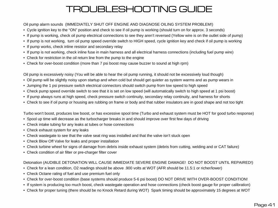
TROUBLESHOOTING GUIDEOil pump alarm sounds (IMMEDIATELY SHUT OFF ENGINE AND DIAGNOSE OILING SYSTEM PROBLEM!)• Cycle ignition key to the “ON” position and check to see if oil pump is working (should turn on for approx. 3 seconds)• If pump is working, check oil pump electrical connections to see they aren’t reversed (Yellow wire is on the outlet side of pump)• If pump is not working, turn oil pump speed override switch to HIGH speed, cycle ignition key and check if oil pump is working• If pump works, check inline resistor and secondary relay• If pump is not working, check inline fuse in main harness and all electrical harness connections (including fuel pump wire)• Check for restriction in the oil return line from the pump to the engine• Check for over-boost condition (more than 7 psi boost may cause buzzer to sound at high rpm)
Oil pump is excessively noisy (You will be able to hear the oil pump running, it should not be excessively loud though)• Oil pump will be slightly noisy upon startup and when cold but should get quieter as system warms and as pump wears in• Jumping the 1 psi pressure switch electrical connectors should switch pump from low speed to high speed• Check pump speed override switch to see that it is set on low speed (will automatically switch to high speed at 1 psi boost)• If pump always runs at high speed, check pressure switch continuity, secondary relay continuity, and harness for shorts• Check to see if oil pump or housing are rubbing on frame or body and that rubber insulators are in good shape and not too tight
Turbo won’t boost, produces low boost, or has excessive spool time (Turbo and exhaust system must be HOT for good turbo response)• Spool up time will decrease as the turbocharger breaks in and should improve over first few days of driving• Check intake tubing for any leaks at tubes or hose connections• Check exhaust system for any leaks• Check wastegate to see that the valve seat ring was installed and that the valve isn’t stuck open• Check Blow Off Valve for leaks and proper installation• Check turbine wheel for signs of damage from debris inside exhaust system (debris from cutting, welding and or CAT failure)• Check condition of air filter or pre-charger filter cover
Detonation (AUDIBLE DETONATION WILL CAUSE IMMEDIATE SEVERE ENGINE DAMAGE! DO NOT BOOST UNTIL REPAIRED!)• Check for a lean condition, O2 readings should be above .900 volts at WOT (AFR should be 11.5:1 or richer/lower)• Check Octane rating of fuel and use premium fuel only• Check for over-boost condition (base systems should produce 5-6 psi boost) DO NOT DRIVE WITH OVER-BOOST CONDITION!• If system is producing too much boost, check wastegate operation and hose connections (check boost gauge for proper calibration)• Check for proper tuning (there should be no Knock Retard during WOT) Spark timing should be approximately 15 degrees at WOT
Page 41

Squires Turbo Systems – Safety Warning - Please Read!
42
• IMPORTANT
• Oil System Warning Buzzer• Your STS™ Turbo System is equipped with a safety system that will alert you in the event that your oil
pump fails. This system is a buzzer that will be heard inside your vehicle.• If you hear this buzzing sound, pull over to the side of the road as soon as possible and contact the
nearest STS Power Dealer. Serious engine damage can occur if the pump stops while your engine is running. With the pump stopped oil will flow out of the turbo and will not return to the engine.
• Premium Fuel• Squires Turbo Systems recommends that you only use Premium Fuel, 91 Octane or better, on vehicles
equipped with the STS™ Turbo System. Premium fuel reduces pinging and early detonation which can cause significant damage to your vehicle.
• Engine Pinging• If you hear pinging in your engine, back off the throttle immediately. Pinging can cause significant
damage to the engine. If you hear pinging, call your local STS Power Dealer immediately.
• Heavy Towing• The STS Turbo System, like other turbo and supercharger systems, under certain heavy towing
situations can create more power than a stock engine can handle. Squires Turbo Systems does not recommend using this system for heavy towing purposes.
• Vehicle modifications• STS Turbo Systems were designed to fit stock vehicles. If you have modified your vehicle, modifications
to the turbo system or your vehicle may be necessary to ensure the proper fit and safe use of the STS Turbo System. Inform your Power Dealer of any aftermarket changes to your vehicle.
• For Off Road Use Only in California
STS Safety Warning and Warranty Notice
SAFETY WARNING – PLEASE READThe STS™ turbo system is designed to provide enhanced power and engine performance. It could cause severe damage to your vehicle if it is not properly installed or if your vehicle is not properly maintained for the system. Under some circumstances, improper installation or use of the STS™ turbo system could result in serious personal injury or even death.
Neither Squires Turbo Systems, Inc. nor its authorized dealers can accept responsibility for the proper maintenance or the proper operation of your vehicle. Please take all necessary precautions to use the STS™turbo system strictly in accordance with all instructions and warnings.
WARRANTY NOTICE – PLEASE READThe liability of Squires Turbo Systems, Inc. and its authorized dealers relating to your use of the STS™ turbo system is strictly limited. Please read the STS™ turbo system limited warranty carefully. In most cases, the warranty is limited to repair or replacement of the system itself and does not cover:
• Any damage to your vehicle or other property that results from your use of the STS™ turbo system• Any personal injury or death that results from your use of the STS™ turbo system• Any adverse effect of the STS™ turbo system on other warranties• Under some circumstances, applicable law may specifically prohibit us from disclaiming responsibility for damage to your vehicle and/or for personal injuries or death caused by your use of the STS™ turbo system, in which case our responsibility will be as provided by law. However, we urge you to exercise the utmost care in properly installing and using the system so as to avoid personal injury and/or damage to your vehicle. You are responsible for using the system safely and for evaluating the effect of such use on other warranties.
Page 43
LIMITED ONE-YEAR WARRANTY
44
Squires Turbo Systems, Inc. warrants to you, the original purchaser of an STS™ turbo system (the “System”), the that System will be free from defects in material and workmanship for a period of one year after the date the System is shipped to you, or, if the System is originally installed on your vehicle by an authorized STS™ service dealer, for a period of one year after the date of installation. This warranty does not apply to any System that has been disassembled, repaired, or otherwise altered by any person other than an authorized STS™ service dealer, nor does it apply to any System that fails as a result of misuse, accident, improper installation, improper or inadequate maintenance, racing, neglect, or any use in an application or environment for which you know or should know the System is not designed or approved.
Who Makes this Warranty This warranty is made by Squires Turbo Systems, Inc., 165 N. 1330 W., Suite C4, Orem, Utah 84057, or by the authorized STS™ service dealer who installed your System. Who is Covered This warranty extends only to the original purchaser of the System for use on the motor vehicle on which the System originally is installed.
What is Covered This warranty covers defects in materials or workmanship in all parts of the System as originally installed on your vehicle. If the System is determined during the warranty period to be defective, and you comply with the terms of this Limited Warranty, an authorized STS™ service dealer or Squires Turbo Systems, Inc., as applicable, will replace any defective parts, or, if replacement is not commercially practicable or cannot be timely made, refund the original purchase price for the System. This warranty covers parts only. If Squires Turbo Systems, Inc. or its authorized STS™ service dealer performs any repair work or installs any replacement part for the System under this warranty, you may be charged for labor costs.
Where and How to Obtain Warranty Service You can obtain warranty service from any authorized STS™ service dealer or directly from Squires Turbo Systems, Inc. It is your responsibility to deliver or ship the defective System to an authorized STS™ service dealer or to Squires Turbo Systems, Inc. at your expense, together with a copy of your invoice or work order and a description of the claimed defect prior to the expiration of the warranty period. To obtain information regarding the location of authorized STS™service dealers or other information regarding this warranty, you may call 1-866-WE-TURBO.
Exceptions and Exclusions This warranty is conditioned upon (i) proper installation and (ii) the vehicle and the System receiving reasonable and necessary maintenance during the warranty period. The warranty does not cover any failure of the System that is caused by misuse, accident, racing, neglect, or any use in an application or environment for which you know or should know the System is not designed or approved. REPLACEMENT OF DEFECTIVE PARTS BY AN AUTHORIZED STS™ SERVICE DEALER, OR, IN APPLICABLE CIRCUMSTANCES, A REFUND OF THE PURCHASE PRICE OF THE SYSTEM, ARE THE SOLE REMEDIES AFFORDED UNDER THIS WARRANTY. IF ANY FAILURE OF THE SYSTEM CAUSES DAMAGE TO ANY OTHER PART OF YOUR VEHICLE OR INJURY TO ANY PERSON OR PROPERTY, THIS WARRANTY DOES NOT COVER SUCH DAMAGE OR INJURY. THIS WARRANTY IS IN LIEU OF AND EXCLUDES ALL OTHER WARRANTIES NOT EXPRESSLY SET FORTH HEREIN, WHETHER EXPRESS OR IMPLIED, INCLUDING BUT NOT LIMITED TO ANY WARRANTIES OF MERCHANTABILITY AND FITNESS FOR A PARTICULAR PURPOSE. IN NO EVENT SHALL THE LIABILITY OF SQUIRES TURBO SYSTEMS, INC. RELATED TO THE SYSTEM EXCEED THE PURCHASE PRICE OF THE SYSTEM. SQUIRES TURBO SYSTEM, INC. SHALL NOT BE LIABLE UNDER ANY CIRCUMSTANCES FOR CONSEQUENTIAL, INDIRECT, SPECIAL, OR INCIDENTAL DAMAGES ARISING FROM OR IN CONNECTION WITH THE USE OF THE SYSTEM ON THE VEHICLE. (SOME STATES DO NOT ALLOW THE EXCLUSION OR LIMITATION OF INCIDENTAL OR CONSEQUENTIAL DAMAGES, SO THE ABOVE LIMITATION OR EXCLUSION MAY NOT APPLY TO YOU.) THIS WARRANTY GIVES YOU SPECIFIC LEGAL RIGHTS AND YOU MAY ALSO HAVE OTHER RIGHTS WHICH VARY FROM STATE TO STATE.

TOWING WARNING• The STS™ Turbo System is NOT recommended for towing and/or heavy hauling. The
Turbocharger will produce more than adequate power and torque for towing. However, turbocharged stock engines, combined with the heavy loading of the engine and extended boost conditions during towing, can produce the following potentially damaging conditions:
• Extreme exhaust gas temperatures (in excess of 1500F) can damage Catalytic Converters, Valves, and Stock Pistons.
• High air intake temperatures (in excess of 200F) can raise combustion temperatures which may cause detonation.
• Extended high RPM driving can cause lean fuel mixtures (in excess of 12:1) resulting in high combustion and exhaust gas temperatures which may cause detonation.
• Heavy loads will produce full boost at very light throttle conditions which may cause lean fuel mixtures (at light throttle positions the PCM is running in Closed Loop which maintains 14.7:1 air fuel ratios).
• High combustion temperatures can develop more heat than the stock spark plugs can dissipate (stock spark plug heat range is too hot) which can cause spark plug damage and detonation.
• Heavy loading and high exhaust temperatures can cause “Boost Creep” and an “Over-Boost”condition which may cause severe engine damage.
• High torque combined with heavy loads can cause extreme transmission temperatures which can damage transmission and/or drive-train components.
• Extended driving periods of high horsepower production can create more combustion heat than the stock cooling system (radiator) can control which may cause engine overheating and severe engine damage.
• WARNING: USE CAUTION AND GOOD JUDGEMENT AND TOW AT YOUR OWN RISK! DO NOT LET THE ENGINE DETONATE DURING BOOST! ANY AUDIBLEDETONATION (PINGING) WILL DAMAGE YOUR ENGINE!
45