Embed Size (px)
Citation preview
94-17352
Diffractive Optics in Adverse Environments
February 24, 1993
Gregory P. Behrmann
Army Research LaboratoryAMSRL-SS-SF
2800 Powder Mill Road
Adelphi, MD 20783
(301) 394-3800
Abstract
An investigation at the Army Research Laboratory is in progress to characterize DOE per-
formance in mil-spec environments. One of the most significant environmental influences is tem-
perature. An analysis of a diffractive lens is presented in which optical performance is describedas a function of temperature. In particular, we review the thermal dependence of focal length
and diffraction efficiency. It is shown that the change in these parameters is independent of lens
shape and relates only to material properties. Athermalized hybrid refractive/diffractive designs
are discussed.
1.0 Introduction
For military and aerospace applications, temperature is one of the more important environmen-
tal influences. Typical military specifications can require a system to operate over a temperature
range of -30°C to 50°C. In fact, it is not uncommon for commercial products to operate over a
significant temperature range. Sometimes, the combination of changes in dimension and index can
affect the optical performance of a system. 1
To date, the effects of temperature on DOEs have received little attention. 2'a Recently, sev-eral researchers 4's'6'7 have independently examined the relationship among temperature, material
properties, and optical performance.In this paper, we will describe focal length as a function of temperature and describe the
temperature dependence of diffraction efficiency. We will show how an athermalized lens can be
designed by combining refractive and diffractive surfaces and discuss its limitations. In addition,
we will present a new designthat is both athermal and achromatic. Finally, we will end with some
concluding remarks.
1D. S. Grey, "Athermalization of Optical Systems," JOSA 38 (1948), p. 542.2A. McKay and J. White, "Effects of Simulated Space EnviIonments on Dichromated Gelatin Hologran_," SPIE
Proc. 1044 (1989), pp. 269-275.aM. Tanigaml, S. Ogata, S. Aoyama, T. Yamashita, and K. Imanaka, "Low-Wavefront Aberration and High
Temperature Stability Molded Micro Fresnel Lens," IEEE Photonics Tech. Left. 1 (1989), pp. 384-385.4J. Jahns, Y. H. Lee, C. A. Burrus Jr., and J. Jewell, "Optical interconnects Using Top-Surface-Emitting Micro-
lasers and Planar Optics," Appl. Opt. 31, (1992), pp. 592-597.
55. C. Londono, W. T. Plummet, and P. P. Clark, "Athermalization with Diffractive Optics," Diffractive Optics:
Design, Fabrication, and Applications 1992, Techical Digest Series 9 (OSA, Washington D.C., 1992), p. 7.5G. P. Behrmann and J. P. Bowen, "Thermal Effects in Diffractive Lenses," Diffractive Optics: Design, Fabrication,
and Applications 1992, Techical Digest Series 9 (OSA, Washington D.C, 1992), p. 8-10.
7G. P. Behrmann and J. P. Bowen, "The Influence of Temperature on Diffractive Lena Performance," accepted
for publication in Applied Optics.
Conf. on Binary Optics, 1993271
PI!GIDtNG PAGE BLANK NOT FILh_..D
https://ntrs.nasa.gov/search.jsp?R=19940012879 2018-08-31T21:58:10+00:00Z
2.00pto-thermal Expansion Coefficient
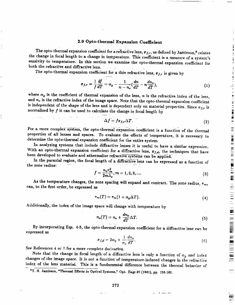
The opto-thermalexpansioncoeffcientfora refractivelens,zl,r,asdefinedby Jamieson,s relates
the change in focallength to a change in temperature. This coefficientisa measure ofa system's
sensivityto temperature. In thissectionwe examine the opto-thermal expansion coefficientforboth the refractiveand diffractivelens........
The opto-thermal expansion coefficientfora thinrefractivelens,zl,r isgivenby=
1 df 1 dn dno.=s,, = f dT = % -n no(_ - n-_), (1)
where _g is the coefficient of thermal expansion of the lens, n is the refractive index of the lens,
and no is the refractive index of tile image space. Note that the opto-thermal expansion coefficient
is independent of the shape of the lens and is dependent only on material properties. Since r,l, _ isnormalized by f it can be used to calculate the change in focal length by
A f = Iz/,rAT. (2)
For a more complex system, the opto-therm_' expansion coefficient is a function of the thermal
propertiesof alllensesand spaces. To evaluatethe effectsof temperature, it is necessary to
determine the opto-thermalexpansion coefficientforthe entiresystem.
In analyzing systems that includediffractivelensesit isusefulto have a similarexpression.
With a_topto-thermal expansion coefficientfor a diffractivelens,zl,d,the techniquesthat have
been developed to evaluateand athermalizerefracti_e_ysternscan be applie&
In the paraxialregion,the focallengthof a diffractlvelenscan be expressedas a functionofthe zone radius: .......
nor2Tn
jr= 2--_o 'm= 1,2,3, .... (3)
_As the temperature changes, the zone spacing will expand and contract. The zone radius, rm,can, to the first order, be expressed as
r,,_(T) = r_(1 + (_oAT). (4)
Additionally, the index of the image space will change with temperature by
dno(V) = r,o+ ,aT. ( )
By incorporating nqs. 4-5, the opto'thermal expansion coefficient for a diffractive lens can beexpressed as
1 dnoz/,d = 2% + ---- (C,)
no dT=
See References 4 or 7 for a more complete derivation.
Note that the change in focal length of a diffractive lens is only a function of ag and indexchanges of the image space. It is not a function of temperature-induced changes ill the refra¢ tire
index of the lens material. This is a fundamental difference between the thermal behavior of
ST. H. Jamieson, "Thermal Effects in Optical Systems," Opt. Engr.20 (1981), pp. 156-160.
272
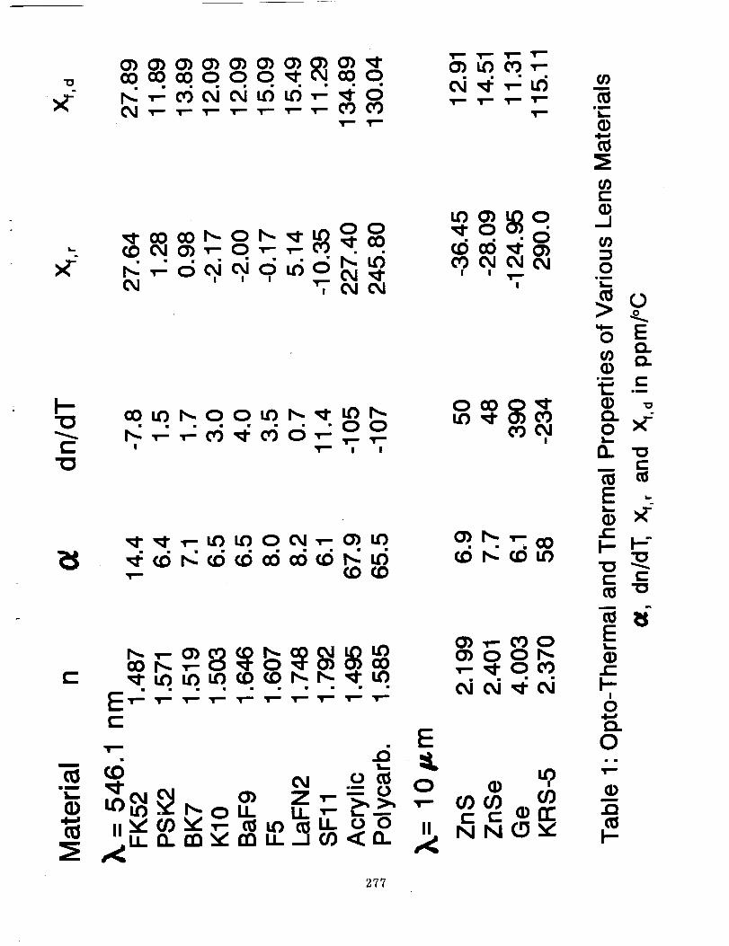
refractive and diffractive lenses. Table 1 shows the relevant parameters and the opto-thermal
expansion coefficients for several optical materials.
Opto-thermal expansion coefficients can be used by a designer to athermalize a system. One
way in which this is achieved is by matching the opto-thermal expansion coefficient of the lens
system to the coefficient of thermal expansion of the mounting material so that the change in
image position corresponds to the change in position of the focal plane. See Fig. 1.
Because zy,r for a refractive singlet and zy,d for a diffractive singlet made of the same material
can be different, it is theoretically possible to design an athermalized hybrid refractive/diffractive
element. Such an element has a refractive power due to the curvature of the surfaces and a
diffractive power due to surface-relief structure. This is pictorially represented in Fig. 2. The
practical limitations on such designs are discussed in the Sec. 4.0.
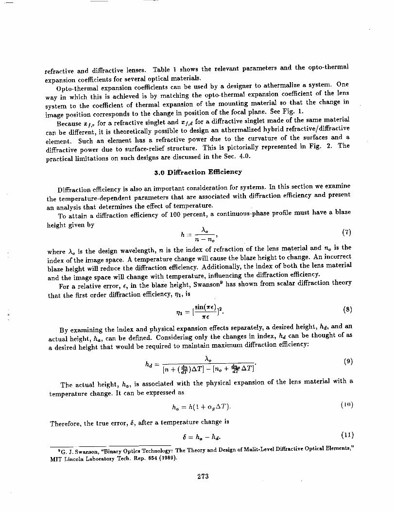
3.0 Diffraction Efficiency
Diffraction efficiency is also an important consideration for systems. In this section we examine
the temperature-dependent parameters that are associated with diffraction efficiency and present
an analysis that determines the effect of temperature.To attain a diffraction efficiency of 100 percent, a continuous-phase profile must have a blaze
height given byh- (7)
n -- 'no
where _o is the design wavelength, n is the index of refraction of the lens material and no is the
index of the image space. A temperature change will cause the blaze height to change. An incorrect
blaze height will reduce the diffraction efficiency. Additionally, the index of both the lens material
and the image space will change with temperature, influencing the diffraction efficiency.
For a relative error, e, in the blaze height, Swanson 9 has shown from scalar diffraction theory
that the first order diffraction efficiency, 771, is
sin(Tre)71 = • (8)
By examining the index and physical expansion effects separately, a desired height, ha, and an
actual height, ha, can be defined. Considering only the changes in index, hd can be thought of as
a desired height that would be required to maintain maximum diffraction efficiency:
_o (9)hd =
In + (_T)AT]- [no + -_T AT] '
The actual height, ha, is associated with the physical expansion of the lens material with a
temperature change. It can be expressed as
ha = h(1 + _gAT). (11_)
Therefore, the true error, _, after a temperature change is
-_ ha --hd. (11)
9G. J. Swanson, "Binary Optics Technology: The Theory and Design of Mullt-Level Diffractive Optical Elements,"
MIT Lincoln Laboratory Tech. Rep. 854 (1989).
273
The relativeerror, e, in Eq. (10) is
, = --. (12)hd :: :::
If we consider optical systems that operate in air, We have-found that, for most materials, the
change in diffraction efficiency due to temperatureeffects is negligible. _s istrue even for plasticswhich have both a high ag and dn/dT.
For example, acrylic has a coefficient of thermal expansion of 65.5 × 10:6°C-1 and a dn/dT of
-125 × 10-_°C-1. If the temperature of a diffractive lens made of acrylic is increased by 30°C, •
would be 0.0056 and the change in diffraction efficlency would be less than 0.i percent.
4.0 Design Examples
In the following section, we show how opto-thermal expansion data can be used to design hybrid
athermalized lens systems. Here we restrict our analysis to the case of an athermallzed doublet
and an athermallzed/achromatized triplet. For systems containing more elements or airspaces, the
same methodology applies.
The total power of a lens, _be, imersed in air, can be expressed as
1
¢t-- (13)
where ft is the focal length of the lens. It follows that for a k-element lens, ¢t can be deterrrdnedby
¢1= ¢1+ + :....+ Ck.hi Eq. 14, Cx is the power of the first lens, and ¢2 is the power of the second lens and so on.
An opto-thermal expansion coefficient for the lens, z/,t, is given by
Zj+,t z _¢1_]1 -Jr- _¢2_f 2 _ ... __ £¢kT,]k. (15)
In Eq. 15, Z/l, z12, and z/k are the corresponding opto-thermal expansion coefficients of theindividual lens elements.
Consider lenses made from polycarbonate. This material offers several advantages: it is inex-
pensive, lightweight, and easy to shape. However, for the refractive case, polycarbonate has an
extremely ]iigh opto-thermal expansion coefficient (245 × 10-e°C-1). This can be attributed to
its large coefficient of thermal expansion and its large dn/dT. For the diffractive Case, the opto:
thernml expansion coefficient is also quite large (130 × 10-6°C-1). Therefore, polycarbonate lenses
are difficult to incorporate in optical systems that must operate over wide temperature ranges.
If it were necessary to athermalize a polycarbonate lens, a hybrid doublet could be designed
to meet this requirement. Consider an f/5 doublet with a focal length of 100 mm operating at
A. equal to 632.8 nm. By using Eqs. 14 and 15, we can selec_ w, wers iJ, tiw refr:_'_iv_ s,,rface
and diffractive surface such that the net opt,,-thermal e×pansi,m ,,wfficienl ,hatches lh,. m,,unf ing
material. For an aluminum mount, rI'ab]e 2 shows the coef]]cients and calcNJaled powers requiredfor athermalization.
As a basis of comparison, it is appropriate to compare the performance of the athermalized
hybrid to an all refractive singlet made from polycarbonate mounted in aluminum.
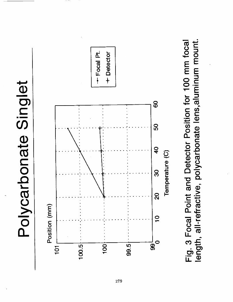
The thermal performance of a refractive singlet is shown in Fig. 3. It is assumed that the
system is perfectiy aiigned at 20°C. If focal length and detector position are plotted as a function
274
of temperature, it is seen that when the system is heated to 50°C, the distance between detector
and focal length is 0.67 ram. This seperation is more than 20 times the tolerable depth of focus for
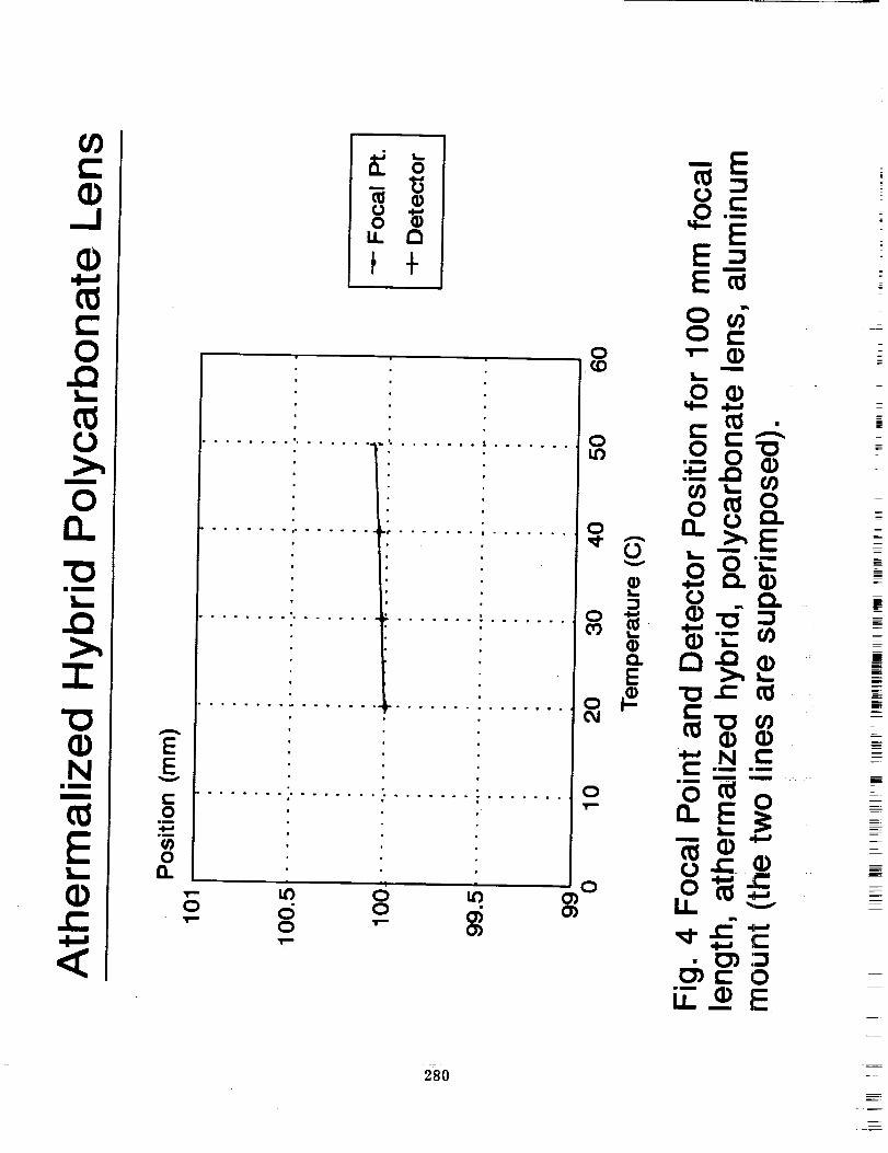
diffraction limited performance.On the other hand, Fig. 4 is a plot of focal length and detector position for the athermalized
hybrid. For a first-order approximation of material properties, the distance between the two remains
the same.This athermalization technique is similar to one used to achromatize refractive and diffractive
surfaces. 10 In achromatization, power is distributed in the refractive and diffractive surfaces based
on the relative dispersions of the lens materials. Typically, the dispersion of a lens material is
measured by its Abbe number, V. Therefore, an achromatized lens with a real object should meet
the following condition:¢, ¢2 Ck (16)
.....For the refractive surface, the Abbe number of polycarbonate is 30. The diffractive surface has an
Abbe number of -3.45. Note tha(in the athermalized hybrid, the refractive power is negative and
the diffractive power is positive. Therefore, the conditions of Eq. 16 are not satisfied and chromatic
aberrations must be addressed.
For diffraction limited performance, the refractive singlet has a bandwidth of 4- 2.94 nm, and the
athermalized doublet has an equivalent bandwidth of 4- 0.1 nm. Thus, the chromatic aberrations are
more severe in the athermalized hybrid element. For polycarbonate, this athermaUzation technique
may only be useful for monochromatic applications.Estelle 11 has examined the requirements for simultaneously athermalizing and achromatizing
refractive lens systems. For the most part, a three-material triplet is required. With three materials,
one can use Eqs. 14-16 to set up a system of 3 equations and 3 unknowns in which to solve for
the necessary power in each element. Other aberrations, for example spherical aberration, can be
reduced by solving for the optimal bending of the lens elements. Estelle studied a family of triplet
solutions consisting of two plastics and one glass element. In the following, due to the unique
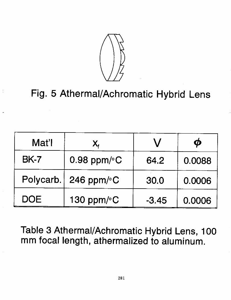
dispersive and thermal behavior of the diffractive lens, we examine the possibility of replacing oneof the three materials with a diffractive surface. See Fig. 5.
Assume now that it were necesssary to design an f/5, 100 mm focal length lens mounted in
aluminum. In this case, the lens must be achromatized over the visible range. If we use BK-7
and polycarbonate, both inexpensive materials, an element can be designed that has the massand volume of a doublet but the performance of triplets discussed by Estelle. Table 3 shows the
calculated powers for a solution with the glass element in front and the diffractive surface on theback. Note that the diffractive surface is relatively weak and would therefore be easier to fabricate.
Additionally, the powers in the refractive components are manufacturable. In fact, similar levels of
performance can be attained in IR lenses. 12 Infrared materials exhibit large changes in index with
temperature. Traditionally it has been difficult to athermalize such systems.
tOT. Stone and N. George, "Hybrid diffractive-refractive lenses and achromats," Applied Optics, 27, (J988) pp.
2960-2971.
11L. R. Estelle, "Third-Order Theory of Thermally Controlled Plastic and Glass Triplets," SPIE Proceedings, 237,
(1980) pp. 392-401._G. Behrmann, "Color Correction in Athermalized Hybrid Lenses," to be presented at OSA Topical Meeting,
Design for Photonics, March 22, 1993.
275
5.0 Conclusions
We have performed an analysis of thermal effects and their influence on the performance of
diffractive lenses. Formulas describing the Change in first-order properties have been presented.
These expressions are useful for designing systems that must operate over wide temperature ranges.Tile opto-thermal expansion coefficient for a diffractive lens has been derived. It is different
from its refractive counterpart in that the focal length of a diffractive lens is not dependent on
temperature-induced changes in refractive index of the lens material. An analysis of the change in
diffraction efficiency due to temperature was performed. We have found for systems operating in
air that the changes are insignificant.A design technique was presented that shows how refractive and diffractive surfaces can be
used togetiier i0 produce hybrids with desirable thermal behavior. For a single hybrid, the amount
of chromatic aberration will usually be increased if the athermal conditions are imposed. It wasalso shown that a diffractive surface can be used to significantly reduce the mass and volume of
all-refractive triplet solutions that are both athermal and achromatic.
276
I--
{-"O
0_1 .v- .w--._-- .I-- .i-- ._-- .r- 0"J L'_
O'j L_ 0") .w-.
O0
, , , "_'; 0,1 0,1
,t.o.L'O L'_I OJ L"_I
I I ,,N,i,I
cO L,L"}I'-,, 0 0 L,{")I',,, "_l" L,_ I""0 (:0 0 '_"
i
E__-_-_-_-_-_-_-
m
im
._J
0we
"8 E
"ID
0
I-- I--"
E
0
0
m
I-
277

I
i
I
(_ount
23 ppm/oC
Fig. 1 Athermalized Lens System
Fig. 2 Athermalized Hybrid Lens
246 ppm/oC-0.0092
3
Xf,d
130 ppm/oC 0.0192
Table 2 Coefficientsl Refractive and
Diffractive Power for 100 mm. focal length, hybridpolycarbonate lens, athermalized to aluminum.
278
m
0
m
0n
V
t-O
0
_a
0
.0 6 .0 -o0
8 " a)
EE
0 t-O •--"
",-EL_0"--
o ,,_¢_c_0 ¢-
o
o oO
o_.
0 --- (D
O=--m
ii
o0=Zllm
279
Q
Nim
m
L_
<
c-O
wm
0O.
0
E=E'_
0 t-o _ (1) -
L_
. . ° • . . • - • . • . • • . = • o • • ...... • ° • • .
| |
o ub
0 T-
Ix. _,_
,¢ x:" _
im
u__Em
280
71
Fig. 5 Athermal/Achromatic Hybrid Lens
Mat'l
BK-7
Polycarb.
DOE
0.98 ppm/oC
246 ppm/oC
130 ppm/oC
V
64.2
30.0
0.0088
0.0006
0.0006
Table 3 Athermal/Achromatic Hybrid Lens, 100mm focal length, athermalized to aluminum.
281
!
i