Embed Size (px)
Citation preview

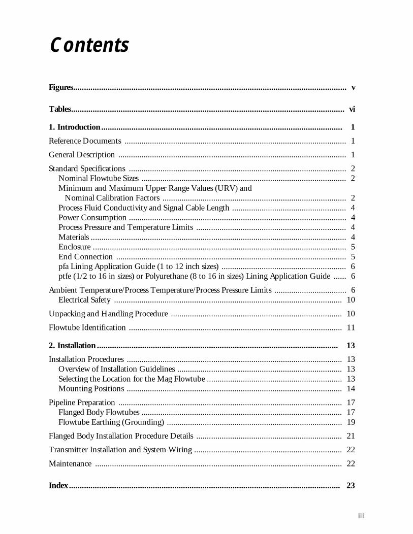
MI 021-386December 1997Instruction
9300A Series Flanged Magnetic Flowtubes
pfa-Lined, 1- through 12-inch Sizesptfe-Lined, 1/2- through 16-inch Sizes
or Polyurethane-Lined, 8- through 16-inch SizesInstallation
FLANGED BODY FLOWTUBE WITH REMOTE TRANSMITTER
FLANGED BODY FLOWTUBE
WITH FLOWTUBE-MOUNTED TRANSMITTER

MI 021-386 – December 1997
Contents
Figures............................................................................................................................... v
Tables............................................................................................................................... vi
1. Introduction ................................................................................................................ 1
Reference Documents ......................................................................................................... 1
General Description ............................................................................................................ 1
Standard Specifications ....................................................................................................... 2Nominal Flowtube Sizes ................................................................................................. 2Minimum and Maximum Upper Range Values (URV) and Nominal Calibration Factors ....................................................................................... 2Process Fluid Conductivity and Signal Cable Length ...................................................... 4Power Consumption ....................................................................................................... 4Process Pressure and Temperature Limits ....................................................................... 4Materials ......................................................................................................................... 4Enclosure ........................................................................................................................ 5End Connection ............................................................................................................. 5pfa Lining Application Guide (1 to 12 inch sizes) ........................................................... 6ptfe (1/2 to 16 in sizes) or Polyurethane (8 to 16 in sizes) Lining Application Guide ...... 6
Ambient Temperature/Process Temperature/Process Pressure Limits .................................. 6Electrical Safety ............................................................................................................ 10
Unpacking and Handling Procedure ................................................................................. 10
Flowtube Identification ..................................................................................................... 11
2. Installation ................................................................................................................ 13
Installation Procedures ...................................................................................................... 13Overview of Installation Guidelines .............................................................................. 13Selecting the Location for the Mag Flowtube ................................................................ 13Mounting Positions ...................................................................................................... 14
Pipeline Preparation .......................................................................................................... 17Flanged Body Flowtubes ............................................................................................... 17Flowtube Earthing (Grounding) ................................................................................... 19
Flanged Body Installation Procedure Details ..................................................................... 21
Transmitter Installation and System Wiring ...................................................................... 22
Maintenance ..................................................................................................................... 22
Index .............................................................................................................................. 23
iii

MI 021-386 – December 1997
iv
v
Figures
1 Typical Flowtube Data Plates ....................................................................................... 11 2 Flanged Body Flowtube Mounted Vertically, Remote Transmitter .............................. 14 3 Flanged Body Flowtube Mounted Vertically, Flowtube-Mounted Transmitter ............ 15 4 Flanged Body Flowtube Mounted Horizontally, Remote Transmitter .......................... 15 5 Flanged Body Flowtube Mounted Horizontally, Flowtube-Mounted Transmitter ....... 15 6 Changing Orientation of Transmitter on Flowtube-Mounted Transmitter .................. 16 7 Pipeline Alignment and Support .................................................................................. 18 8 Use of Grounding Rings when Transmitter is in Remote Location .............................. 19 9 Use of Grounding Rings when Transmitter Mounted to Flowtube .............................. 19

vi
Tables
1 Min/Max URV and Calibration Factors ....................................................................... 2 2 Liner vs. Flange Type ................................................................................................... 5 3 Approximate Mass ....................................................................................................... 5 4 Flanged Tubes (Transmitter Remote Mounted) pfa-Lined Tubes ................................. 6 5 Flanged Tubes (Transmitter Remote Mounted) ptfe-Lined Tubes ............................... 7 6 Flanged Tubes (Transmitter Remote Mounted) Polyurethane-Lined Tubes ................. 7 7 Flanged Tubes (Transmitter Tube Mounted) pfa-Lined Tubes .................................... 8 8 Flanged Tubes (Transmitter Tube Mounted) ptfe-Lined Tubes ................................... 8 9 Flanged Tubes (Transmitter Tube Mounted) Polyurethane-Lined Tubes ..................... 9
10 Flange Pressure-Temperature Limits of 9300A pfa-Lined/ptfe-lined Flowtubes ............ 9 11 Electrical Classification ................................................................................................ 10 12 Flanged Body Flowtube End-to-End Dimensions ........................................................ 17 13 Pipeline Alignment Specification .................................................................................. 18 14 Inside Diameters of Grounding Rings .......................................................................... 20 15 Maximum Mounting-Nut Torques for Flanged-Body Flowtubes ................................. 21
1. Introduction
These flanged, magnetic flowtubes, together with an 8000, IMT10/20/25 I/A Series Mag-netic Flow Transmitter, combine to form an easy-to-use, versatile magnetic flowmeter. The flowmeter is an economical microprocessor-based magnetic flow system. This flowtube can be used with most common fluids, from everyday conductive liquids to very difficult-to-handle conductive liquids. The transmitter converts the low level, high impedance signal from the flowtube to a standard scaled transmission signal that is proportional to flow rate, either 4 to 20 mA, digital, or pulse output.
Reference Documents
General DescriptionThe 9300A Series Flanged Magnetic Flowtubes are available in pfa-lined 25 to 300 mm (1 to 12 in), polyurethane-lined 200 to 400 mm (8 to 16 in) sizes, and ptfe-lined 15 to 400 mm (1/2 to 16 in) sizes. The flowtube, in conjunction with an 8000, IMT10/20/25 I/A Series Magnetic Flow Transmitter, combines to form a magnetic flowmeter system. The transmitter can mount directly to the flowtube, or can be mounted in a remote location to a surface or pipe. In remote transmitter applications, the flowtube and transmitter are interconnected by a signal cable having a maximum length of 300 m (1000 ft).
The transmitters use a pulsed-dc technique to energize the flux-producing coils of the flow-tube. As the process liquid passes through the magnetic field in the flowtube, low-level voltage pulses are developed across a pair of electrodes. The voltage level of these pulses is directly pro-portional to the average velocity of the liquid. The transmitters convert the voltage pulse to both a standard 4 to 20 mA and/or pulse output signal. The 4 to 20 mA signal is used with a suitable receiver to indicate, record, and/or control a variable. The proportional pulse output can be used for totalization, and can be configured for either a high-rate or low-rate pulse. With an I/A Series Transmitter, a digital output signal is also provided for flowmeters serving
Document Description
MI 021-369 8000 Series Transmitters, Remote Mounted, Installation
MI 021-370 8000 Series Transmitters, Flowtube Mounted, Installation
MI 021-372 IMT10 Series Transmitters, Remote Mounted, InstallationMI 021-373 IMT10 Series Transmitters, Flowtube Mounted, Installation
MI 021-382 IMT20 Series Transmitters, Installation
MI 021-387 IMT25 Series Transmitters, Installation and Wiring
MI 021-393 IMT25L Series Transmitters, Installation
TI 27-71f Magnetic Flowtube Materials Selection Guide
TI 027-072 Magnetic Flowmeter Liquid Conductivity Tables
1
MI 021-386 – December 1997 1. Introduction
as a primary device in the I/A Series system. Details of the output signals are given in the applicable transmitter instruction.
This instruction relates to the installation of the flowtube portion of a magnetic flowmeter system. For installation, wiring, operation, configuration, and maintenance details relating to the flowmeter system, refer to the applicable transmitter documents.
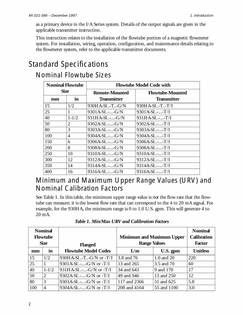
Standard SpecificationsNominal Flowtube Sizes
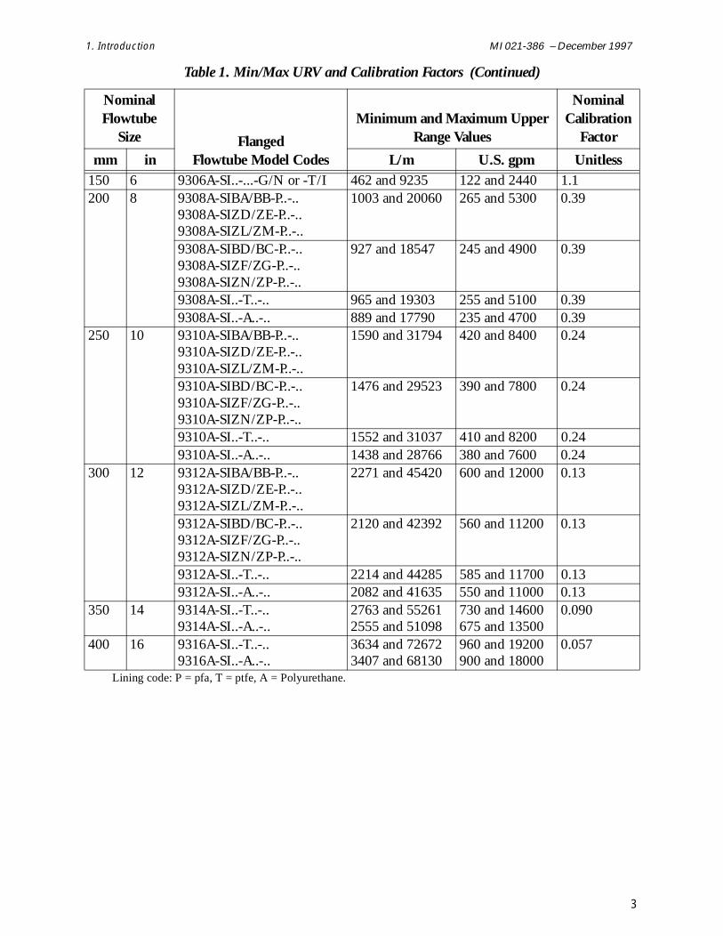
Minimum and Maximum Upper Range Values (URV) and Nominal Calibration FactorsSee Table 1. In this table, the minimum upper range value is not the flow rate that the flow-tube can measure; it is the lowest flow rate that can correspond to the 4 to 20 mA signal. For example, for the 930HA, the minimum range is 0 to 1.0 U.S. gpm. This will generate 4 to 20 mA.
Nominal Flowtube Size
Flowtube Model Code with
Remote-Mounted Transmitter
Flowtube-Mounted Transmittermm in
15 1/2 930HA-SI..-T..-G/N 930HA-SI..-T..-T/I25 1 9301A-SI..-...-G/N 9301A-SI..-...-T/I40 1-1/2 931HA-SI..-...-G/N 931HA-SI..-...-T/I50 2 9302A-SI..-...-G/N 9302A-SI..-...-T/I80 3 9303A-SI..-...-G/N 9303A-SI..-...-T/I100 4 9304A-SI..-...-G/N 9304A-SI..-...-T/I150 6 9306A-SI..-...-G/N 9306A-SI..-...-T/I200 8 9308A-SI..-...-G/N 9308A-SI..-...-T/I250 10 9310A-SI..-...-G/N 9310A-SI..-...-T/I300 12 9312A-SI..-...-G/N 9312A-SI..-...-T/I350 14 9314A-SI..-...-G/N 9314A-SI..-...-T/I400 16 9316A-SI..-...-G/N 9316A-SI..-...-T/I
Table 1. Min/Max URV and Calibration Factors
Nominal Flowtube
Size Flanged Flowtube Model Codes
Minimum and Maximum Upper Range Values
Nominal Calibration
Factor
mm in L/m U.S. gpm Unitless15 1/2 930HA-SI..-T..-G/N or -T/I 3.8 and 76 1.0 and 20 22025 1 9301A-SI..-...-G/N or -T/I 13 and 265 3.5 and 70 6040 1-1/2 931HA-SI..-...-G/N or -T/I 34 and 643 9 and 170 1750 2 9302A-SI..-...-G/N or -T/I 49 and 946 13 and 250 1280 3 9303A-SI..-...-G/N or -T/I 117 and 2366 31 and 625 5.8100 4 9304A-SI..-...-G/N or -T/I 208 and 4164 55 and 1100 3.0
2
1. Introduction MI 021-386 – December 1997
150 6 9306A-SI..-...-G/N or -T/I 462 and 9235 122 and 2440 1.1200 8 9308A-SIBA/BB-P..-..
9308A-SIZD/ZE-P..-..9308A-SIZL/ZM-P..-..
1003 and 20060 265 and 5300 0.39
9308A-SIBD/BC-P..-..9308A-SIZF/ZG-P..-..9308A-SIZN/ZP-P..-..
927 and 18547 245 and 4900 0.39
9308A-SI..-T..-.. 965 and 19303 255 and 5100 0.399308A-SI..-A..-.. 889 and 17790 235 and 4700 0.39
250 10 9310A-SIBA/BB-P..-..9310A-SIZD/ZE-P..-..9310A-SIZL/ZM-P..-..
1590 and 31794 420 and 8400 0.24
9310A-SIBD/BC-P..-..9310A-SIZF/ZG-P..-..9310A-SIZN/ZP-P..-..
1476 and 29523 390 and 7800 0.24
9310A-SI..-T..-.. 1552 and 31037 410 and 8200 0.249310A-SI..-A..-.. 1438 and 28766 380 and 7600 0.24
300 12 9312A-SIBA/BB-P..-..9312A-SIZD/ZE-P..-..9312A-SIZL/ZM-P..-..
2271 and 45420 600 and 12000 0.13
9312A-SIBD/BC-P..-..9312A-SIZF/ZG-P..-..9312A-SIZN/ZP-P..-..
2120 and 42392 560 and 11200 0.13
9312A-SI..-T..-.. 2214 and 44285 585 and 11700 0.139312A-SI..-A..-.. 2082 and 41635 550 and 11000 0.13
350 14 9314A-SI..-T..-..9314A-SI..-A..-..
2763 and 552612555 and 51098
730 and 14600675 and 13500
0.090
400 16 9316A-SI..-T..-..9316A-SI..-A..-..
3634 and 726723407 and 68130
960 and 19200900 and 18000
0.057
Lining code: P = pfa, T = ptfe, A = Polyurethane.
Table 1. Min/Max URV and Calibration Factors (Continued)
Nominal Flowtube
Size Flanged Flowtube Model Codes
Minimum and Maximum Upper Range Values
Nominal Calibration
Factor
mm in L/m U.S. gpm Unitless
3
MI 021-386 – December 1997 1. Introduction
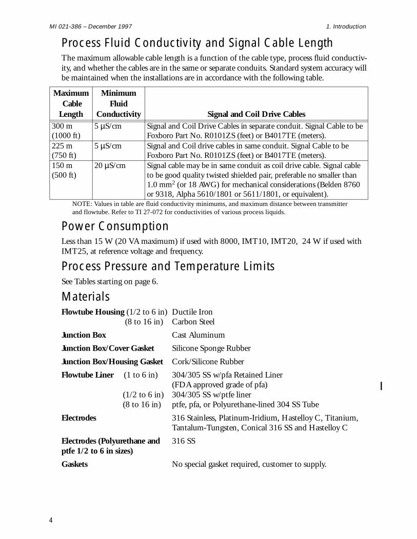
Process Fluid Conductivity and Signal Cable LengthThe maximum allowable cable length is a function of the cable type, process fluid conductiv-ity, and whether the cables are in the same or separate conduits. Standard system accuracy will be maintained when the installations are in accordance with the following table.
Power ConsumptionLess than 15 W (20 VA maximum) if used with 8000, IMT10, IMT20, 24 W if used with IMT25, at reference voltage and frequency.
Process Pressure and Temperature LimitsSee Tables starting on page 6.
MaterialsFlowtube Housing (1/2 to 6 in) Ductile Iron
(8 to 16 in) Carbon Steel
Junction Box Cast Aluminum
Junction Box/Cover Gasket Silicone Sponge Rubber
Junction Box/Housing Gasket Cork/Silicone Rubber
Flowtube Liner (1 to 6 in) 304/305 SS w/pfa Retained Liner (FDA approved grade of pfa)
(1/2 to 6 in) 304/305 SS w/ptfe liner(8 to 16 in) ptfe, pfa, or Polyurethane-lined 304 SS Tube
Electrodes 316 Stainless, Platinum-Iridium, Hastelloy C, Titanium, Tantalum-Tungsten, Conical 316 SS and Hastelloy C
Electrodes (Polyurethane and 316 SSptfe 1/2 to 6 in sizes)
Gaskets No special gasket required, customer to supply.
Maximum Cable Length
Minimum Fluid
Conductivity Signal and Coil Drive Cables300 m(1000 ft)
5 µS/cm Signal and Coil Drive Cables in separate conduit. Signal Cable to be Foxboro Part No. R0101ZS (feet) or B4017TE (meters).
225 m(750 ft)
5 µS/cm Signal and Coil drive cables in same conduit. Signal Cable to be Foxboro Part No. R0101ZS (feet) or B4017TE (meters).
150 m(500 ft)
20 µS/cm Signal cable may be in same conduit as coil drive cable. Signal cable to be good quality twisted shielded pair, preferable no smaller than 1.0 mm2 (or 18 AWG) for mechanical considerations (Belden 8760 or 9318, Alpha 5610/1801 or 5611/1801, or equivalent).
NOTE: Values in table are fluid conductivity minimums, and maximum distance between transmitter and flowtube. Refer to TI 27-072 for conductivities of various process liquids.
4
1. Introduction MI 021-386 – December 1997
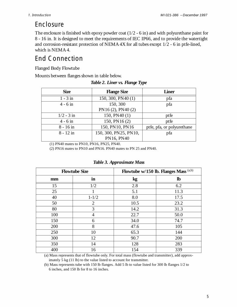
Enclosure The enclosure is finished with epoxy powder coat (1/2 - 6 in) and with polyurethane paint for 8 - 16 in. It is designed to meet the requirements of IEC IP66, and to provide the watertight and corrosion-resistant protection of NEMA 4X for all tubes except 1/2 - 6 in ptfe-lined, which is NEMA 4.
End ConnectionFlanged Body Flowtube
Mounts between flanges shown in table below.
Table 2. Liner vs. Flange Type
Size Flange Size Liner1 - 3 in 150, 300, PN40 (1) pfa4 - 6 in 150, 300
PN16 (2), PN40 (2)pfa
1/2 - 3 in 150, PN40 (1) ptfe4 - 6 in 150, PN16 (2) ptfe8 - 16 in 150, PN10, PN16 ptfe, pfa, or polyurethane8 - 12 in 150, 300, PN25, PN10,
PN16, PN40pfa
(1) PN40 mates to PN10, PN16, PN25, PN40.(2) PN16 mates to PN10 and PN16. PN40 mates to PN 25 and PN40.
Table 3. Approximate Mass
Flowtube Size Flowtube w/150 lb. Flanges Mass (a,b)
mm in kg lb15 1/2 2.8 6.225 1 5.1 11.340 1-1/2 8.0 17.550 2 10.5 23.280 3 14.2 31.3100 4 22.7 50.0150 6 34.0 74.7200 8 47.6 105250 10 65.3 144300 12 90.7 200350 14 128 283400 16 154 339
(a) Mass represents that of flowtube only. For total mass (flowtube and transmitter), add approx-imately 5 kg (11 lb) to the value listed to account for transmitter.
(b) Mass represents tube with 150 lb flanges. Add 5 lb to value listed for 300 lb flanges 1/2 to 6 inches, and 150 lb for 8 to 16 inches.
5

MI 021-386 – December 1997 1. Introduction
pfa Lining Application Guide (1 to 12 inch sizes)pfa provides excellent corrosion, chemical, stress crack, thermal shock and hydrolysis resis-tance. Also, suitable for applications requiring high/low temperatures, anti-stick and high purity properties. Refer to Table 10 for process pressure and temperature limits for the flow-tubes. Also see TI 27-71f for liner material recommendations for common process fluids.
NOTE: The pfa liner may be non-uniform in appearance, having dark and light shading. This condition is inherent in the pfa molding process and does not in any way affect the durability or performance of the tube.
ptfe (1/2 to 16 in sizes) or Polyurethane (8 to 16 in sizes) Lining Application GuidePolyurethane withstands effects of highly abrasive fluids, and ptfe withstands effects of severely corrosive and mildly abrasive fluids. Refer to TI 27-71f for detailed liner recommen-dations for common process fluids.
Ambient Temperature/Process Temperature/Process Pressure Limits
Table 4. Flanged Tubes (Transmitter Remote Mounted) pfa-Lined Tubes
Influence
Reference Operating Conditions
Normal Operating Conditions Operating Limits
Ambient Temperature
25°C77°F
-40 to + 70°C-40 to +158°F
-40 and +70°C-40 and +158°F
Process Temperature
25°C77°F
-40 to +180°C-40 to +356°F
-40 and +180°C-40 and +356°F
Process Pressure1 to 12inches
0.525 MPa75 psi
Full Vacuum to 5.1 MPa at 38°C (740 psi at 100°F)
5.1 MPa at 38°C (740 psi at 100°F)
Full Vacuum 4.4 MPa at 180°C (645 psi at 356°F)
4.4 MPa at 180°C (645 psi at 356°F)
6
1. Introduction MI 021-386 – December 1997
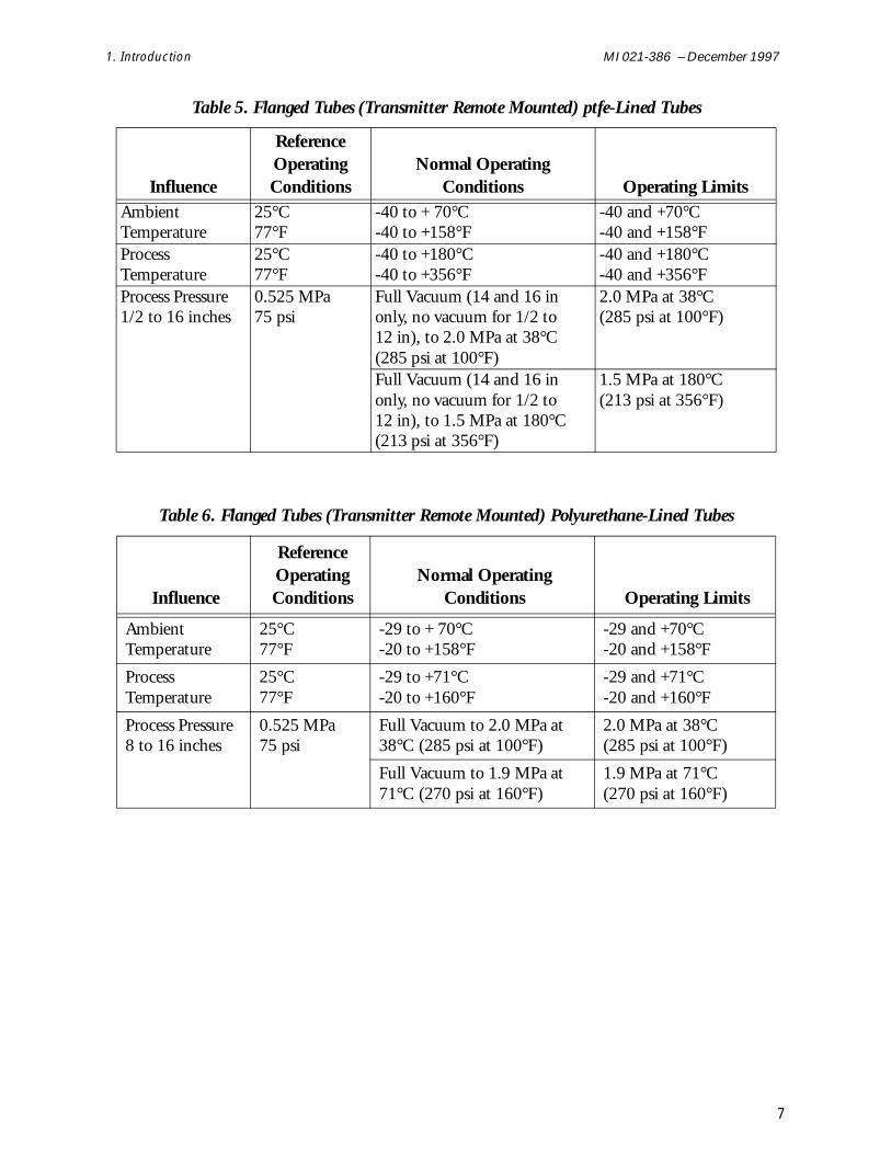
Table 5. Flanged Tubes (Transmitter Remote Mounted) ptfe-Lined Tubes
Influence
Reference Operating Conditions
Normal Operating Conditions Operating Limits
Ambient Temperature
25°C77°F
-40 to + 70°C-40 to +158°F
-40 and +70°C-40 and +158°F
Process Temperature
25°C77°F
-40 to +180°C-40 to +356°F
-40 and +180°C-40 and +356°F
Process Pressure1/2 to 16 inches
0.525 MPa75 psi
Full Vacuum (14 and 16 in only, no vacuum for 1/2 to 12 in), to 2.0 MPa at 38°C (285 psi at 100°F)
2.0 MPa at 38°C (285 psi at 100°F)
Full Vacuum (14 and 16 in only, no vacuum for 1/2 to 12 in), to 1.5 MPa at 180°C (213 psi at 356°F)
1.5 MPa at 180°C (213 psi at 356°F)
Table 6. Flanged Tubes (Transmitter Remote Mounted) Polyurethane-Lined Tubes
Influence
Reference Operating Conditions
Normal Operating Conditions Operating Limits
Ambient Temperature
25°C77°F
-29 to + 70°C-20 to +158°F
-29 and +70°C-20 and +158°F
Process Temperature
25°C77°F
-29 to +71°C-20 to +160°F
-29 and +71°C-20 and +160°F
Process Pressure8 to 16 inches
0.525 MPa75 psi
Full Vacuum to 2.0 MPa at 38°C (285 psi at 100°F)
2.0 MPa at 38°C (285 psi at 100°F)
Full Vacuum to 1.9 MPa at 71°C (270 psi at 160°F)
1.9 MPa at 71°C (270 psi at 160°F)
7
MI 021-386 – December 1997 1. Introduction
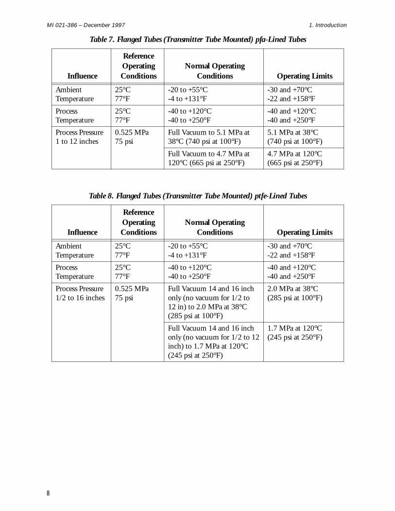
Table 7. Flanged Tubes (Transmitter Tube Mounted) pfa-Lined Tubes
Influence
Reference Operating Conditions
Normal Operating Conditions Operating Limits
Ambient Temperature
25°C77°F
-20 to +55°C-4 to +131°F
-30 and +70°C-22 and +158°F
Process Temperature
25°C77°F
-40 to +120°C-40 to +250°F
-40 and +120°C-40 and +250°F
Process Pressure1 to 12 inches
0.525 MPa75 psi
Full Vacuum to 5.1 MPa at 38°C (740 psi at 100°F)
5.1 MPa at 38°C (740 psi at 100°F)
Full Vacuum to 4.7 MPa at 120°C (665 psi at 250°F)
4.7 MPa at 120°C (665 psi at 250°F)
Table 8. Flanged Tubes (Transmitter Tube Mounted) ptfe-Lined Tubes
Influence
Reference Operating Conditions
Normal Operating Conditions Operating Limits
Ambient Temperature
25°C77°F
-20 to +55°C-4 to +131°F
-30 and +70°C-22 and +158°F
Process Temperature
25°C77°F
-40 to +120°C-40 to +250°F
-40 and +120°C-40 and +250°F
Process Pressure1/2 to 16 inches
0.525 MPa75 psi
Full Vacuum 14 and 16 inch only (no vacuum for 1/2 to 12 in) to 2.0 MPa at 38°C (285 psi at 100°F)
2.0 MPa at 38°C (285 psi at 100°F)
Full Vacuum 14 and 16 inch only (no vacuum for 1/2 to 12 inch) to 1.7 MPa at 120°C (245 psi at 250°F)
1.7 MPa at 120°C (245 psi at 250°F)
8
1. Introduction MI 021-386 – December 1997
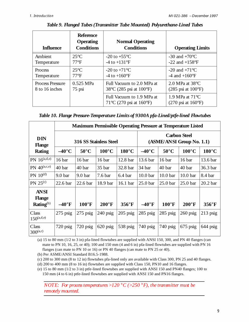
NOTE: For process temperatures >120 °C (>250 °F), the transmitter must be remotely mounted.
Table 9. Flanged Tubes (Transmitter Tube Mounted) Polyurethane-Lined Tubes
Influence
Reference Operating Conditions
Normal Operating Conditions Operating Limits
Ambient Temperature
25°C77°F
-20 to +55°C-4 to +131°F
-30 and +70°C-22 and +158°F
Process Temperature
25°C77°F
-20 to +71°C-4 to +160°F
-20 and +71°C-4 and +160°F
Process Pressure8 to 16 inches
0.525 MPa75 psi
Full Vacuum to 2.0 MPa at 38°C (285 psi at 100°F)
2.0 MPa at 38°C (285 psi at 100°F)
Full Vacuum to 1.9 MPa at 71°C (270 psi at 160°F)
1.9 MPa at 71°C (270 psi at 160°F)
Table 10. Flange Pressure-Temperature Limits of 9300A pfa-Lined/ptfe-lined Flowtubes
DIN Flange Rating
Maximum Permissible Operating Pressure at Temperature Listed
316 SS Stainless SteelCarbon Steel
(ASME/ANSI Group No. 1.1)
–40°C 50°C 100°C 180°C –40°C 50°C 100°C 180°C
PN 16(a,d,e) 16 bar 16 bar 16 bar 12.8 bar 13.6 bar 16 bar 16 bar 13.6 bar
PN 40(a,c,e) 40 bar 40 bar 35 bar 32.8 bar 34 bar 40 bar 40 bar 36.3 bar
PN 10(d) 9.0 bar 9.0 bar 7.6 bar 6.4 bar 10.0 bar 10.0 bar 10.0 bar 8.4 bar
PN 25(c) 22.6 bar 22.6 bar 18.9 bar 16.1 bar 25.0 bar 25.0 bar 25.0 bar 20.2 bar
ANSI Flange
Rating(b) –40°F 100°F 200°F 356°F –40°F 100°F 200°F 356°F
Class 150(a,d,e)
275 psig 275 psig 240 psig 205 psig 285 psig 285 psig 260 psig 213 psig
Class 300(a,c)
720 psig 720 psig 620 psig 538 psig 740 psig 740 psig 675 psig 644 psig
(a) 15 to 80 mm (1/2 to 3 in) pfa-lined flowtubes are supplied with ANSI 150, 300, and PN 40 flanges (can mate to PN 10, 16, 25, or 40); 100 and 150 mm (4 and 6 in) pfa-lined flowtubes are supplied with PN 16 flanges (can mate to PN 10 or 16) or PN 40 flanges (can mate to PN 25 or 40).
(b) Per ASME/ANSI Standard B16.5-1988.(c) 200 to 300 mm (8 to 12 in) flowtubes pfa-lined only are available with Class 300, PN 25 and 40 flanges.(d) 200 to 400 mm (8 to 16 in) flowtubes are supplied with Class 150, PN10 and 16 flanges.(e) 15 to 80 mm (1/2 to 3 in) ptfe-lined flowtubes are supplied with ANSI 150 and PN40 flanges; 100 to
150 mm (4 to 6 in) ptfe-lined flowtubes are supplied with ANSI 150 and PN16 flanges.
9
MI 021-386 – December 1997 1. Introduction
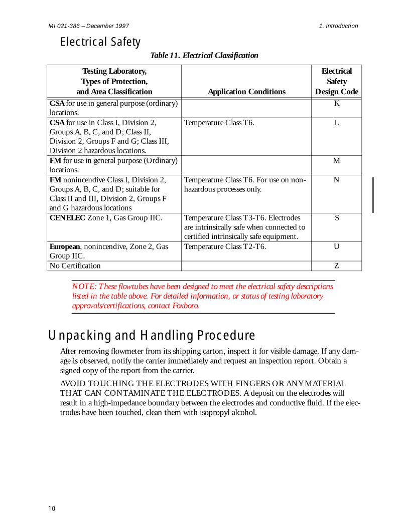
Electrical Safety
NOTE: These flowtubes have been designed to meet the electrical safety descriptions listed in the table above. For detailed information, or status of testing laboratory approvals/certifications, contact Foxboro.
Unpacking and Handling ProcedureAfter removing flowmeter from its shipping carton, inspect it for visible damage. If any dam-age is observed, notify the carrier immediately and request an inspection report. Obtain a signed copy of the report from the carrier.
AVOID TOUCHING THE ELECTRODES WITH FINGERS OR ANY MATERIAL THAT CAN CONTAMINATE THE ELECTRODES. A deposit on the electrodes will result in a high-impedance boundary between the electrodes and conductive fluid. If the elec-trodes have been touched, clean them with isopropyl alcohol.
Table 11. Electrical Classification
Testing Laboratory,Types of Protection,
and Area Classification Application Conditions
Electrical Safety
Design CodeCSA for use in general purpose (ordinary) locations.
K
CSA for use in Class I, Division 2, Groups A, B, C, and D; Class II, Division 2, Groups F and G; Class III, Division 2 hazardous locations.
Temperature Class T6. L
FM for use in general purpose (Ordinary) locations.
M
FM nonincendive Class I, Division 2, Groups A, B, C, and D; suitable for Class II and III, Division 2, Groups F and G hazardous locations
Temperature Class T6. For use on non-hazardous processes only.
N
CENELEC Zone 1, Gas Group IIC. Temperature Class T3-T6. Electrodes are intrinsically safe when connected to certified intrinsically safe equipment.
S
European, nonincendive, Zone 2, Gas Group IIC.
Temperature Class T2-T6. U
No Certification Z
10
1. Introduction MI 021-386 – December 1997
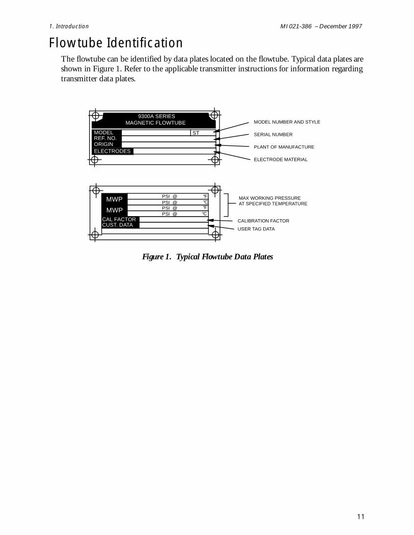
Flowtube IdentificationThe flowtube can be identified by data plates located on the flowtube. Typical data plates are shown in Figure 1. Refer to the applicable transmitter instructions for information regarding transmitter data plates.
Figure 1. Typical Flowtube Data Plates
9300A SERIESMAGNETIC FLOWTUBE
MODELREF. NO.ORIGINELECTRODES
ST
CAL FACTORCAL FACTORCUST. DATA
MWP
MWP
PSI @PSI @PSI @PSI @
°F°C
°C°F
MODEL NUMBER AND STYLE
SERIAL NUMBER
PLANT OF MANUFACTURE
ELECTRODE MATERIAL
MAX WORKING PRESSUREAT SPECIFIED TEMPERATURE
CALIBRATION FACTOR
USER TAG DATA
11

MI 021-386 – December 1997 1. Introduction
12

2. Installation
Installation Procedures
Overview of Installation Guidelines When properly installed, these magflow tubes are capable of providing high accuracy and durability while operating under real life conditions. To get maximum performance from the tube, select an appropriate location in the pipeline and avoid the factors that create bending loads at the flowtube. These factors are highlighted below in general terms and covered specif-ically in the detailed installation instructions.
It is very important that:
♦ A location be selected that will ensure a full flowtube under all operating conditions.
♦ The pipe line and flanges are aligned per the detailed instructions.
♦ Gaskets are centered on the ends of the tube.
♦ Flange bolts are tightened carefully to produce a uniform, well-centered load on the tube.
♦ Torque limits are not exceeded. (By following the installation instruction details, reliable joints can be made without exceeding these limits.)
♦ You allow approximately 5 pipe diameters of straight pipe upstream of the flow-tube and 3 pipe diameters downstream.
♦ If mating pipe is lined, metal or plastic grounding rings be installed on each end of the flowtube.
Selecting the Location for the Mag Flowtube The flowtube can be installed in plastic or metal (magnetic or non-magnetic) piping. Usually the flowtube tube can be placed at any convenient location in the pipeline, but to insure good performance, the location should be reviewed relative to the factors listed below:
♦ It is essential for accuracy that the tube be completely full during operation. Hori-zontal, vertical, or sloping positions are acceptable, but some positions require special attention to be sure that the tube remains full. In addition to obvious prob-lem locations such as down flowing vertical runs, consider areas where air pockets may form and where siphoning action or low pressure areas could create voids.
♦ The effects of upstream disturbances, such as valves and elbows, are difficult to predict, but in nearly all cases, standard accuracy will be realized if there are at least 5 pipe diameters of straight pipe upstream of the flowtube. Downstream distur-bances that are 3 or more pipe diameters from the center of the tube do not affect the measurement accuracy. The inside diameter of the piping should be the same as, or larger than, the nominal size of the flowtube. Flowtubes can be placed in larger nominal size pipelines by using tapered conical reducers. The small ends of
13
MI 021-386 – December 1997 2. Installation
the reducers can be directly coupled to the flowtube and have a maximum included angle of 16°.
♦ If the flowtube is to be used to measure a slurry flow, it is important for accuracy to select a location where the velocities of the slurry components will be nearly equal and high enough to ensure good mixing.
To ensure good service life:
♦ Avoid areas that may have large stresses, such as water hammer or severe shaking of the pipeline.
♦ Provide protection from freezing.
♦ With slurries, do not position the electrodes in such a way that a bend or other pipeline feature would cause large solid particles to strike the electrodes.
♦ The tube enclosure is rated for NEMA 4X, NEMA 4, or IEC IP66 protection and has wide ambient temperature limits, but the tube should be protected from chemical spills and direct exposure to high temperature radiant heat sources.
Select a site with good accessibility for installation.
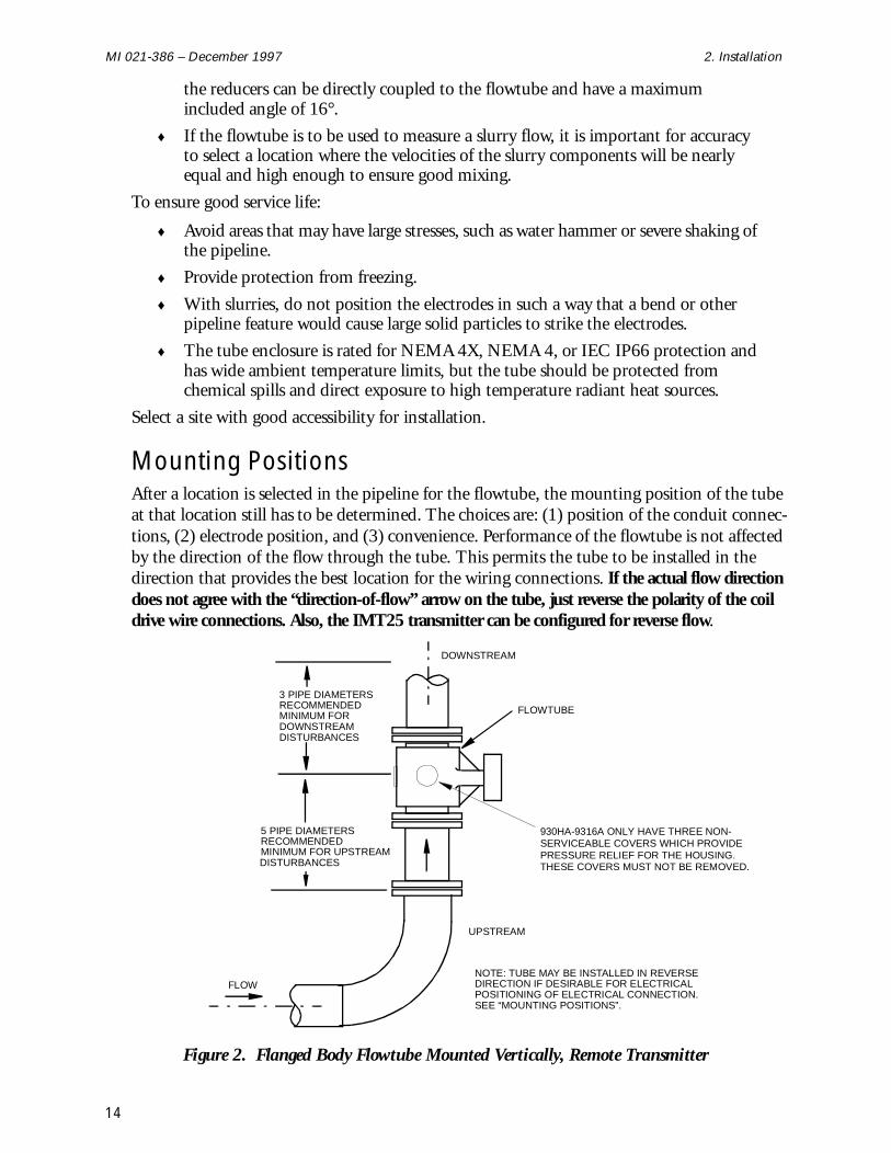
Mounting Positions After a location is selected in the pipeline for the flowtube, the mounting position of the tube at that location still has to be determined. The choices are: (1) position of the conduit connec-tions, (2) electrode position, and (3) convenience. Performance of the flowtube is not affected by the direction of the flow through the tube. This permits the tube to be installed in the direction that provides the best location for the wiring connections. If the actual flow direction does not agree with the “direction-of-flow” arrow on the tube, just reverse the polarity of the coil drive wire connections. Also, the IMT25 transmitter can be configured for reverse flow.
Figure 2. Flanged Body Flowtube Mounted Vertically, Remote Transmitter
NOTE: TUBE MAY BE INSTALLED IN REVERSEDIRECTION IF DESIRABLE FOR ELECTRICALPOSITIONING OF ELECTRICAL CONNECTION.SEE “MOUNTING POSITIONS”.
3 PIPE DIAMETERSRECOMMENDEDMINIMUM FOR
5 PIPE DIAMETERSRECOMMENDEDMINIMUM FOR UPSTREAM
FLOWTUBE
DISTURBANCES
DOWNSTREAMDISTURBANCES
DOWNSTREAM
UPSTREAM
FLOW
930HA-9316A ONLY HAVE THREE NON-SERVICEABLE COVERS WHICH PROVIDEPRESSURE RELIEF FOR THE HOUSING. THESE COVERS MUST NOT BE REMOVED.
14
2. Installation MI 021-386 – December 1997
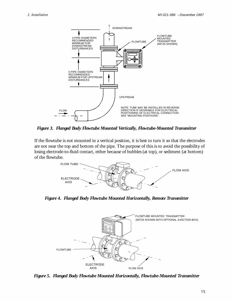
Figure 3. Flanged Body Flowtube Mounted Vertically, Flowtube-Mounted Transmitter
If the flowtube is not mounted in a vertical position, it is best to turn it so that the electrodes are not near the top and bottom of the pipe. The purpose of this is to avoid the possibility of losing electrode-to-fluid contact, either because of bubbles (at top), or sediment (at bottom) of the flowtube.
Figure 4. Flanged Body Flowtube Mounted Horizontally, Remote Transmitter
Figure 5. Flanged Body Flowtube Mounted Horizontally, Flowtube-Mounted Transmitter
NOTE: TUBE MAY BE INSTALLED IN REVERSEDIRECTION IF DESIRABLE FOR ELECTRICALPOSITIONING OF ELECTRICAL CONNECTION.SEE “MOUNTING POSITIONS”.
3 PIPE DIAMETERSRECOMMENDEDMINIMUM FOR
5 PIPE DIAMETERSRECOMMENDEDMINIMUM FOR UPSTREAM
FLOWTUBE
DISTURBANCES
DOWNSTREAMDISTURBANCES
DOWNSTREAM
UPSTREAM
FLOW
FLOWTUBEMOUNTEDTRANSMITTER(IMT25 SHOWN)
ELECTRODEAXIS
FLOW AXIS
FLOW TUBE
ELECTRODEAXIS FLOW AXIS
FLOWTUBE
FLOWTUBE MOUNTED TRANSMITTER(IMT25 SHOWN WITH OPTIONAL JUNCTION BOX)
15
MI 021-386 – December 1997 2. Installation
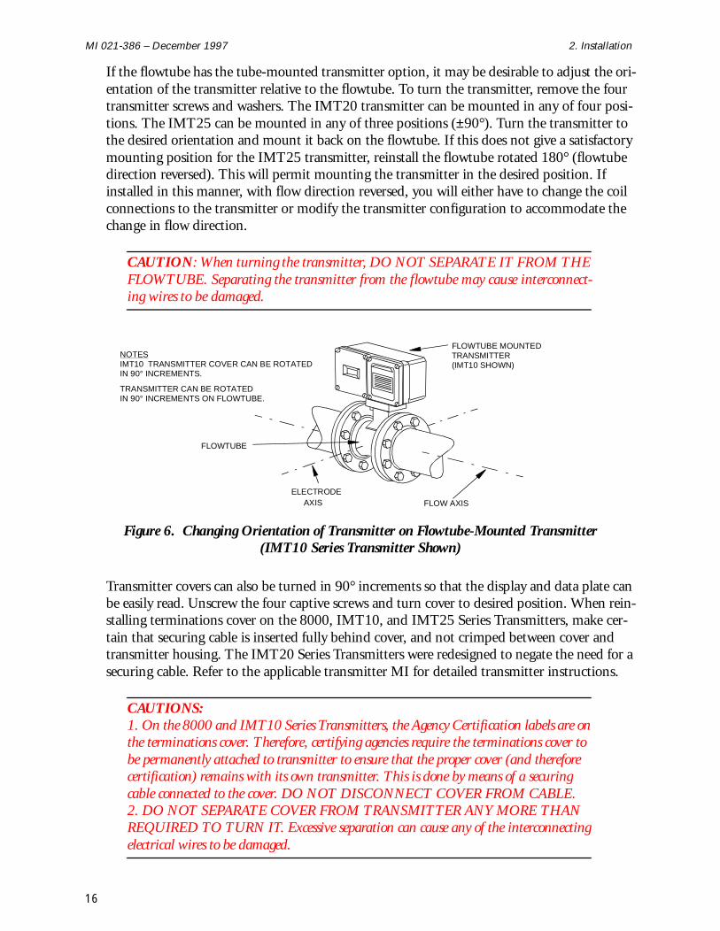
If the flowtube has the tube-mounted transmitter option, it may be desirable to adjust the ori-entation of the transmitter relative to the flowtube. To turn the transmitter, remove the four transmitter screws and washers. The IMT20 transmitter can be mounted in any of four posi-tions. The IMT25 can be mounted in any of three positions (±90°). Turn the transmitter to the desired orientation and mount it back on the flowtube. If this does not give a satisfactory mounting position for the IMT25 transmitter, reinstall the flowtube rotated 180° (flowtube direction reversed). This will permit mounting the transmitter in the desired position. If installed in this manner, with flow direction reversed, you will either have to change the coil connections to the transmitter or modify the transmitter configuration to accommodate the change in flow direction.
CAUTION: When turning the transmitter, DO NOT SEPARATE IT FROM THE FLOWTUBE. Separating the transmitter from the flowtube may cause interconnect-ing wires to be damaged.
Figure 6. Changing Orientation of Transmitter on Flowtube-Mounted Transmitter (IMT10 Series Transmitter Shown)
Transmitter covers can also be turned in 90° increments so that the display and data plate can be easily read. Unscrew the four captive screws and turn cover to desired position. When rein-stalling terminations cover on the 8000, IMT10, and IMT25 Series Transmitters, make cer-tain that securing cable is inserted fully behind cover, and not crimped between cover and transmitter housing. The IMT20 Series Transmitters were redesigned to negate the need for a securing cable. Refer to the applicable transmitter MI for detailed transmitter instructions.
CAUTIONS: 1. On the 8000 and IMT10 Series Transmitters, the Agency Certification labels are on the terminations cover. Therefore, certifying agencies require the terminations cover to be permanently attached to transmitter to ensure that the proper cover (and therefore certification) remains with its own transmitter. This is done by means of a securing cable connected to the cover. DO NOT DISCONNECT COVER FROM CABLE.2. DO NOT SEPARATE COVER FROM TRANSMITTER ANY MORE THAN REQUIRED TO TURN IT. Excessive separation can cause any of the interconnecting electrical wires to be damaged.
ELECTRODEAXIS FLOW AXIS
FLOWTUBE
FLOWTUBE MOUNTEDTRANSMITTER(IMT10 SHOWN)
NOTESIMT10 TRANSMITTER COVER CAN BE ROTATEDIN 90° INCREMENTS.
TRANSMITTER CAN BE ROTATEDIN 90° INCREMENTS ON FLOWTUBE.
16
2. Installation MI 021-386 – December 1997
Pipeline Preparation
Flanged Body Flowtubes
Flowtube Dimensions For complete information, refer to the dimensional prints listed in “Reference Documents” on page 1. The table below lists the Flowtube End-to-End dimensions.
Flange Types and Materials The pipe and flange material can be magnetic, non-magnetic metal, or plastic without affect-ing the accuracy of the flowtube. To help control the stresses on the liner flanged ends, it is best to use a flange type that has a raised face I.D. equal to the pipeline I.D., such as a welding neck or socket welding flange. This assures full gasket contact for more even loading of the liner ends of the flowtube and permits higher bolting torques without over-compressing the gasket. Flange types that do not provide full surface contact with the gasket can be used, but with reduced bolt torques and careful attention to alignment.
Pipeline Support and AlignmentAdequately support the pipeline to carry its weight when full and to control pipeline motions such as may be caused by water hammer or other disturbances within the piping system.
In cases where temperature differences will occur, make provisions to accommodate thermal expansions in a way that will preserve the initial alignment of the piping at the flowtube.
Align the pipe and flanges as shown in Figure 7.
Table 12. Flanged Body Flowtube End-to-End Dimensions
Flowtube Size
Flowtube Model Code
End-to-End Dimensions(Does not include gaskets)
mm in mm in
15 1/2 930HA-SI..-T..-..-.. 200 7.87
25 1 9301A-SI..-...-..-.. 200 7.87
40 1-1/2 931HA-SI..-...-..-.. 200 7.87
50 2 9302A-SI..-...-..-.. 200 7.87
80 3 9303A-SI..-...-..-.. 200 7.87
100 4 9304A-SI..-...-..-.. 250 9.84
150 6 9306A-SI..-...-..-.. 300 11.81
200 8 9308A-SI..-...-..-.. 350 13.78
250 10 9310A-SI..-...-..-.. 450 17.72
300 12 9312A-SI..-...-..-.. 500 19.69
350 14 9314A-SI..-...-..-.. 550 21.65
400 16 9316A-SI..-...-.. 600 23.62
17
MI 021-386 – December 1997 2. Installation
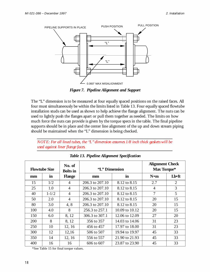
Figure 7. Pipeline Alignment and Support
The “L” dimension is to be measured at four equally spaced positions on the raised faces. All four must simultaneously be within the limits listed in Table 13. Four equally spaced flowtube installation studs can be used as shown to help achieve the flange alignment. The nuts can be used to lightly push the flanges apart or pull them together as needed. The limits on how much force the nuts can provide is given by the torque specs in the table. The final pipeline supports should be in place and the center line alignment of the up and down stream piping should be maintained when the “L” dimension is being checked.
NOTE: For all lined tubes, the “L” dimension assumes 1/8 inch thick gaskets will be used against liner flange faces.
Table 13. Pipeline Alignment Specification
Flowtube SizeNo. of
Bolts in Flange
“L” DimensionAlignment Check
Max Torque*
mm in mm in N•m Lb•ft
15 1/2 4 206.3 to 207.10 8.12 to 8.15 2.7 225 1.0 4 206.3 to 207.10 8.12 to 8.15 4 340 1-1/2 4 206.3 to 207.10 8.12 to 8.15 7 550 2.0 4 206.3 to 207.10 8.12 to 8.15 20 1580 3.0 4, 8 206.3 to 207.10 8.12 to 8.15 20 15
100 4.0 8 256.3 to 257.1 10.09 to 10.12 20 15150 6.0 8, 12 306.3 to 307.1 12.06 to 12.09 27 20200 8 8, 12 356 to 357 14.03 to 14.06 31 23250 10 12, 16 456 to 457 17.97 to 18.00 31 23300 12 12,16 506 to 507 19.94 to 19.97 45 33350 14 12, 16 556 to 557 21.90 to 21.93 45 33400 16 16 606 to 607 23.87 to 23.90 45 33*See Table 15 for final torque values.
0.060" MAX MISALIGNMENT
PIPELINE SUPPORTS IN PLACE PUSH POSITION PULL POSITION
“L”
“L”
18
2. Installation MI 021-386 – December 1997
Flowtube Earthing (Grounding)
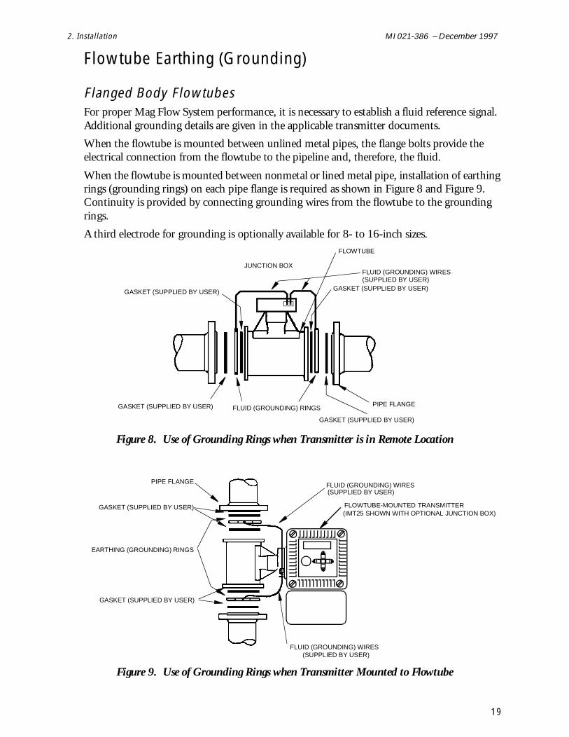
Flanged Body Flowtubes For proper Mag Flow System performance, it is necessary to establish a fluid reference signal. Additional grounding details are given in the applicable transmitter documents.
When the flowtube is mounted between unlined metal pipes, the flange bolts provide the electrical connection from the flowtube to the pipeline and, therefore, the fluid.
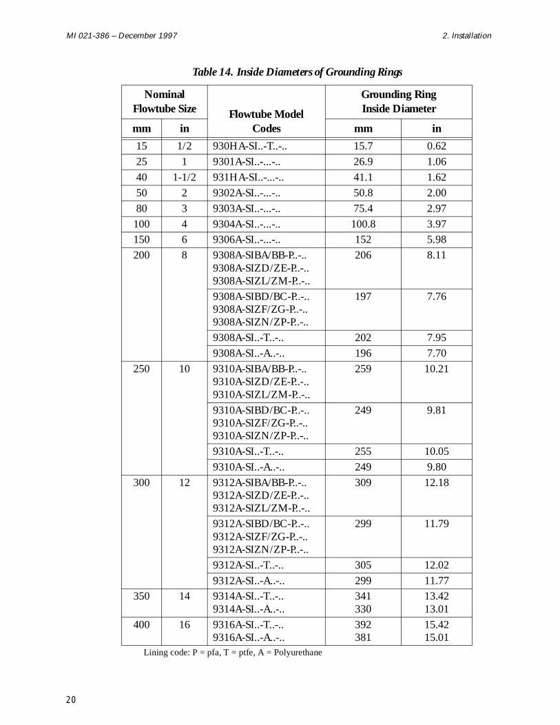
When the flowtube is mounted between nonmetal or lined metal pipe, installation of earthing rings (grounding rings) on each pipe flange is required as shown in Figure 8 and Figure 9. Continuity is provided by connecting grounding wires from the flowtube to the grounding rings.
A third electrode for grounding is optionally available for 8- to 16-inch sizes.
Figure 8. Use of Grounding Rings when Transmitter is in Remote Location
Figure 9. Use of Grounding Rings when Transmitter Mounted to Flowtube
FLUID (GROUNDING) WIRESJUNCTION BOX
GASKET (SUPPLIED BY USER)
FLOWTUBE
GASKET (SUPPLIED BY USER)
GASKET (SUPPLIED BY USER) FLUID (GROUNDING) RINGS
GASKET (SUPPLIED BY USER)
PIPE FLANGE
(SUPPLIED BY USER)
PIPE FLANGE
GASKET (SUPPLIED BY USER)
EARTHING (GROUNDING) RINGS
GASKET (SUPPLIED BY USER)
FLUID (GROUNDING) WIRES
FLUID (GROUNDING) WIRES
FLOWTUBE-MOUNTED TRANSMITTER(IMT25 SHOWN WITH OPTIONAL JUNCTION BOX)
(SUPPLIED BY USER)
(SUPPLIED BY USER)
19
MI 021-386 – December 1997 2. Installation
Table 14. Inside Diameters of Grounding Rings
Nominal Flowtube Size Flowtube Model
Codes
Grounding Ring Inside Diameter
mm in mm in
15 1/2 930HA-SI..-T..-.. 15.7 0.62
25 1 9301A-SI..-...-.. 26.9 1.06
40 1-1/2 931HA-SI..-...-.. 41.1 1.62
50 2 9302A-SI..-...-.. 50.8 2.00
80 3 9303A-SI..-...-.. 75.4 2.97
100 4 9304A-SI..-...-.. 100.8 3.97150 6 9306A-SI..-...-.. 152 5.98
200 8 9308A-SIBA/BB-P..-..9308A-SIZD/ZE-P..-..9308A-SIZL/ZM-P..-..
206 8.11
9308A-SIBD/BC-P..-..9308A-SIZF/ZG-P..-..9308A-SIZN/ZP-P..-..
197 7.76
9308A-SI..-T..-.. 202 7.95
9308A-SI..-A..-.. 196 7.70
250 10 9310A-SIBA/BB-P..-..9310A-SIZD/ZE-P..-..9310A-SIZL/ZM-P..-..
259 10.21
9310A-SIBD/BC-P..-..9310A-SIZF/ZG-P..-..9310A-SIZN/ZP-P..-..
249 9.81
9310A-SI..-T..-.. 255 10.05
9310A-SI..-A..-.. 249 9.80
300 12 9312A-SIBA/BB-P..-..9312A-SIZD/ZE-P..-..9312A-SIZL/ZM-P..-..
309 12.18
9312A-SIBD/BC-P..-..9312A-SIZF/ZG-P..-..9312A-SIZN/ZP-P..-..
299 11.79
9312A-SI..-T..-.. 305 12.02
9312A-SI..-A..-.. 299 11.77350 14 9314A-SI..-T..-..
9314A-SI..-A..-..341330
13.4213.01
400 16 9316A-SI..-T..-..9316A-SI..-A..-..
392381
15.4215.01
Lining code: P = pfa, T = ptfe, A = Polyurethane
20
2. Installation MI 021-386 – December 1997
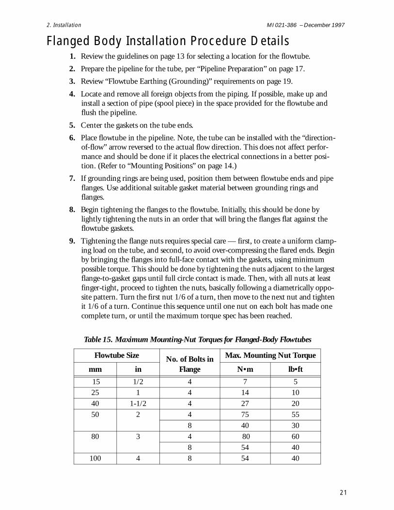
Flanged Body Installation Procedure Details 1. Review the guidelines on page 13 for selecting a location for the flowtube.
2. Prepare the pipeline for the tube, per “Pipeline Preparation” on page 17.
3. Review “Flowtube Earthing (Grounding)” requirements on page 19.
4. Locate and remove all foreign objects from the piping. If possible, make up and install a section of pipe (spool piece) in the space provided for the flowtube and flush the pipeline.
5. Center the gaskets on the tube ends.
6. Place flowtube in the pipeline. Note, the tube can be installed with the “direction-of-flow” arrow reversed to the actual flow direction. This does not affect perfor-mance and should be done if it places the electrical connections in a better posi-tion. (Refer to “Mounting Positions” on page 14.)
7. If grounding rings are being used, position them between flowtube ends and pipe flanges. Use additional suitable gasket material between grounding rings and flanges.
8. Begin tightening the flanges to the flowtube. Initially, this should be done by lightly tightening the nuts in an order that will bring the flanges flat against the flowtube gaskets.
9. Tightening the flange nuts requires special care — first, to create a uniform clamp-ing load on the tube, and second, to avoid over-compressing the flared ends. Begin by bringing the flanges into full-face contact with the gaskets, using minimum possible torque. This should be done by tightening the nuts adjacent to the largest flange-to-gasket gaps until full circle contact is made. Then, with all nuts at least finger-tight, proceed to tighten the nuts, basically following a diametrically oppo-site pattern. Turn the first nut 1/6 of a turn, then move to the next nut and tighten it 1/6 of a turn. Continue this sequence until one nut on each bolt has made one complete turn, or until the maximum torque spec has been reached.
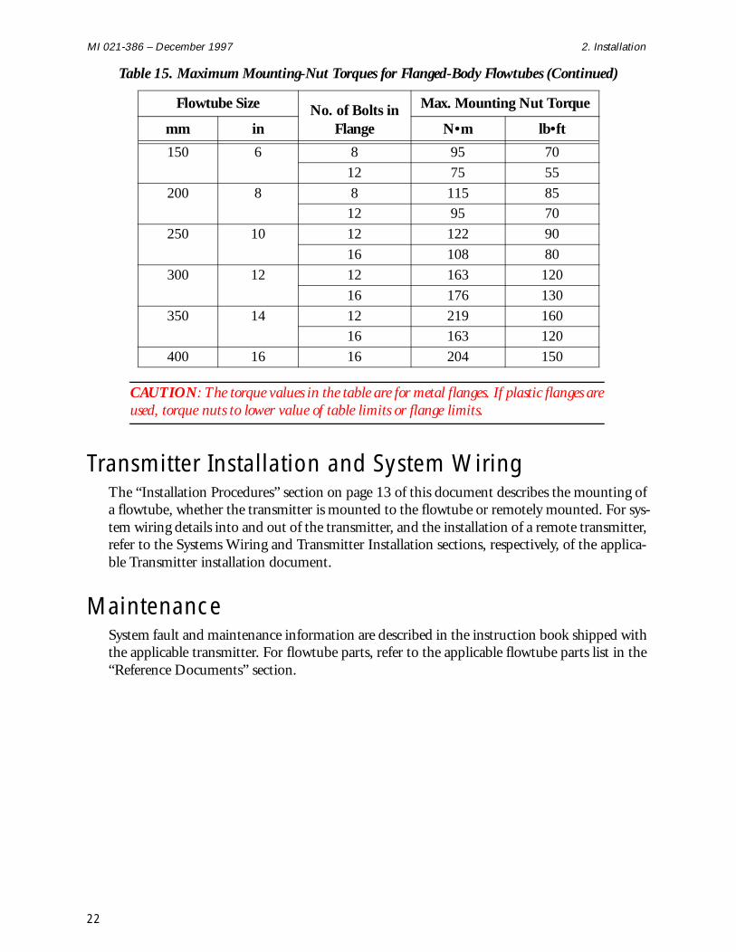
Table 15. Maximum Mounting-Nut Torques for Flanged-Body Flowtubes
Flowtube Size No. of Bolts in Flange
Max. Mounting Nut Torque
mm in N•m lb•ft
15 1/2 4 7 5 25 1 4 14 10
40 1-1/2 4 27 20
50 2 4 75 55
8 40 30
80 3 4 80 60
8 54 40100 4 8 54 40
21
MI 021-386 – December 1997 2. Installation
CAUTION: The torque values in the table are for metal flanges. If plastic flanges are used, torque nuts to lower value of table limits or flange limits.
Transmitter Installation and System Wiring The “Installation Procedures” section on page 13 of this document describes the mounting of a flowtube, whether the transmitter is mounted to the flowtube or remotely mounted. For sys-tem wiring details into and out of the transmitter, and the installation of a remote transmitter, refer to the Systems Wiring and Transmitter Installation sections, respectively, of the applica-ble Transmitter installation document.
Maintenance System fault and maintenance information are described in the instruction book shipped with the applicable transmitter. For flowtube parts, refer to the applicable flowtube parts list in the “Reference Documents” section.
150 6 8 95 70
12 75 55
200 8 8 115 8512 95 70
250 10 12 122 90
16 108 80
300 12 12 163 120
16 176 130
350 14 12 219 16016 163 120
400 16 16 204 150
Table 15. Maximum Mounting-Nut Torques for Flanged-Body Flowtubes (Continued)
Flowtube Size No. of Bolts in Flange
Max. Mounting Nut Torque
mm in N•m lb•ft
22

Index
CCable Length 4Conductivity 4
EElectrical Classification 10Enclosure 5End Connections 5
IIdentification 11Installation Procedures 13
MMaterials 4Mounting Positions 14
PPFA Lining Application Guide 6Pipeline Preparation 17Power Consumption 4Process Fluid Conductivity 4Process Pressure and Temperature Limits 4
RReference Documents 1
SSanitary Flowtube Installation 22Selecting The Location 13Selecting the Location 13Specifications 2System Wiring 22
TTransmitter Installation 22
23

MI 021-386 – December 1997 Index
UUnpacking 10Unpacking and Handling Procedure 10
.
ISSUE DATES OCT 1995 MAY 1996 MAR 1997 OCT 1997 DEC 1997
Vertical lines to right of text or illustrations indicate areas changed at last issue date.
The Foxboro Company33 Commercial StreetFoxboro, MA 02035-2099United States of Americahttp://www.foxboro.comInside U.S.: 1-888-FOXBORO (1-888-369-2676)Outside U.S.: Contact your local Foxboro Representative.Facsimile: (508) 549-4992
Foxboro and I/A Series are registered trademarks of The Foxboro Company.Siebe is a registered trademark of Siebe, plc.Hastelloy is a trademark of Haynes International, Inc.Neoprene is a trademark of E. I. duPont de Nemours & Co.
Copyright 1995-1997 by The Foxboro CompanyAll rights reserved
A Siebe Group Company MB 100 Printed in U.S.A 1297


![[PSS 1-6F2 A] 8000A Series Compact Magnetic Flowtubes · PSS 1-6F2 A Page 2 SUPERIOR REPUTATION FOR DEPENDABILITY AND QUALITY Foxboro introduced magnetic flow measurement systems](https://img.pdfslide.us/doc/110x75/5ac019bc7f8b9a433f8b5f94/pss-1-6f2-a-8000a-series-compact-magnetic-1-6f2-a-page-2-superior-reputation-for.jpg)