Embed Size (px)
Citation preview
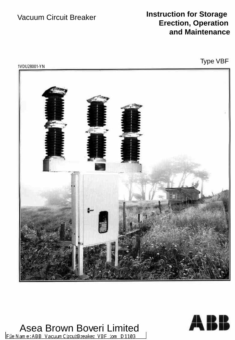
Vacuum Circuit Breaker Instruction for Storage Erection, Operation and Maintenance
Type VBF1VDU28001-YN
Asea Brown Boveri Limited

Outdoor Vacuum Circuit Breaker Type VBF36
List of contents
1. General.
2. Design.
3. Function.
4. Erection.
5. Commissioning
6. Maintenance.
7. Breaker With Spring Charged Mechanism.
8. Breaker With Magnetic Actuator Mechanism.
9. Breaker Pole.
10. List Of Drawings.
VBF 36
Instructions for Erection, Operation & Maintenance.
1.0 General
1.1 Validitv :
This operating instruction is applicable for Outdoor Vacuum Circuit Breaker. type VBF.
1.2 Type designation : VBF 36 16 25
Outdoor Vacuum Circuit Breaker
Rated voltage -36 kV
Rated normal current
16 for 1600A
Rated breaking capacity- 25 kA
1.3 Specifications :Specifications are contained in the order documentation and on the name plate.
l ype - Vacuum Circuit Breaker VBF 36 Sr. Number - Brcakcr production Serial NumberYear - Year of manufactureStandard - IEC - 56 Rated voltage - 36 kVFrequency - 50 Hz Insulation level - 70/170 kV PeakNormal current - 1600 Amp. Short circuit Breaking current - 25 kA Duration of short circuit - 3 Sec.Short circuit making current - 63 kAOperating sequence - 0-0.3S-CO-3 Min -COWeight - 800 Kg. Approx.Auxiliary voltage Closing coil - Rated voltage of closing coilOperating coil - Rated voltage of opening coil Motor (if applicable) - Rated voltage spring charging Instruction Manual - 1VDU28001-YN
1
1.4 Weight of the Circuit Breaker :
The weight of a complete circuit breaker is approximately 800 Kg. contributed by ...
Weight of poles-500 Kg.
Weight of mechanisrn-100 Kg.
Weight of mounting structure-200 Kg.
1.5 Storage :
1.5.1 General
The medium voltage circuit breaker type VBF are delivered firmly secured to the floor/bottom of
their containers or crates and must always be transported or stored with care. The circuit breaker
is transshipped in suitable packing in the open (OFF) position and with closing spring discharged.
1.5.2 Receipt :
Each delivery is to be checked on receipt for ...
*Completeness & correctness.
(Check against order and delivery documents)
*Any possible damage in transit & material losses.
Abnormality, if any, must be notified immediately to :
*ABB, Nashik
*The forwarding agent & the insurance company
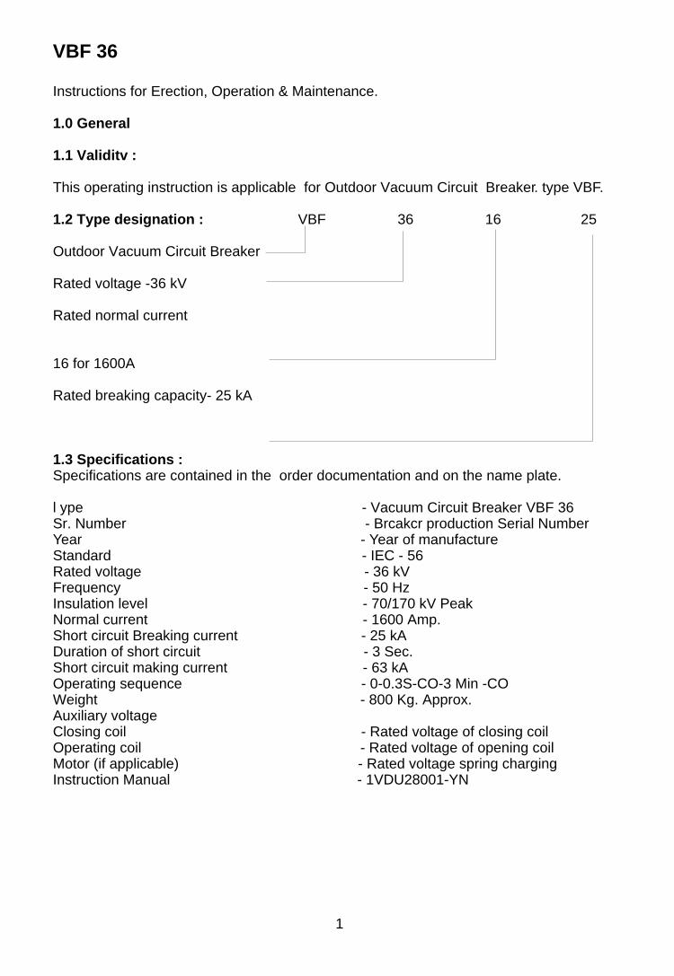
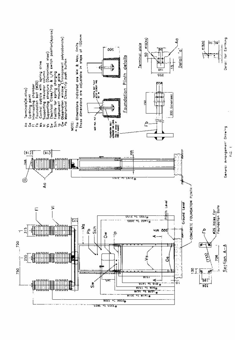
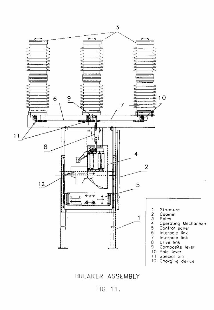
2.Design (Fig. 1 )
The circuit breaker type VBF is a three pole vacuum circuit-breaker and designed in a column
type construction with spring stored energy operating mechanism mounted beneath the middle
pole. It consists of :
- Three breaker poles - FI - Support structure - Vs
- Control cabinet with spring stored energy mechanism - Cs
- Actuator rod and connecting links - Ds & Ts
- Pole support duct - Or
2
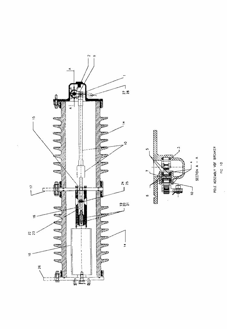
2.1 Breaker Pole :
The breaker pole (ref fig. 10) consists of
- Insulator body - 14
- Vacuum interrupier - 18
- Bottom current collector - 16
- Upper & lower terminal - 26 & 17
The poles are filled with a dry air (Nitrogen) individually at a pressure of 1 .2 bar (abs).
3. Function
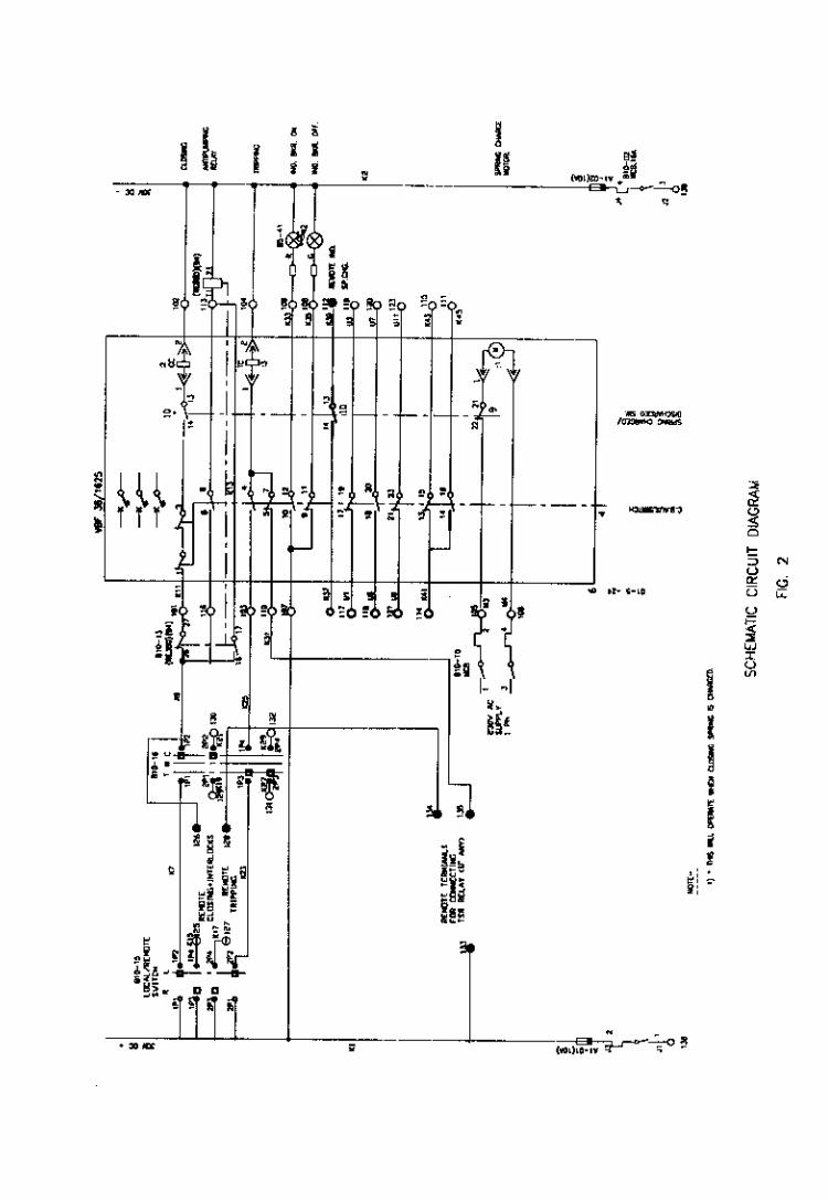
3.1 The typical schematic circuit diagram (Fig. 2) of the breaker shows how the switching
ON and switching OFF commands are given to operate the circuit breaker.
The control circuit can also be referred in the order related engineering drawings.
3.2 Switching operations.
3.2.1 Starting conditions.
As supplied from Asea Brown Boveri Ltd., Nashik, the circuit breaker will be in open
position and closing spring in discharged condition. When the control supply is given to
the breaker, the closing spring will be charged automatically with the help of the spring
charging motor. After charging the spring, the circuit breaker will show the mechanical
indication of 'Spring Charged' from the mechanism observation window.
3.2.2. "Closing" Operation :
To close the circuit breaker, a "CLOSE" control element i.e. closing magnet is actuated ,
whereby the spring stored energy mechanism will release and thus the linkage system
moves the moving contact of all the three poles upward, closing the circuit breaker. This
movement also exerts a contact pressure of desired magnitude.
3.3.3 "Opening" Operation :
To open the circuit breaker, a "OPEN" control element i.e. opening magnet is actuated
whereby the energy stored in a opening spring gets released anci thus the linkage
system moves in reverse direction to move the moving contacts in downward direction,
thus separating the contacts of the circuit breaker.
3
4. Erection
4.1 General:
- As supplied from M/s. Asea Brown Boveri Ltd., Nashik, the circuit breakers are complete in
all the respects with all the necessary setting for smooth and trouble free operations of the
breaker. All the moving parts of the circuit breaker are positioned correctly and coupled
together and they are well secured with the fasteners.
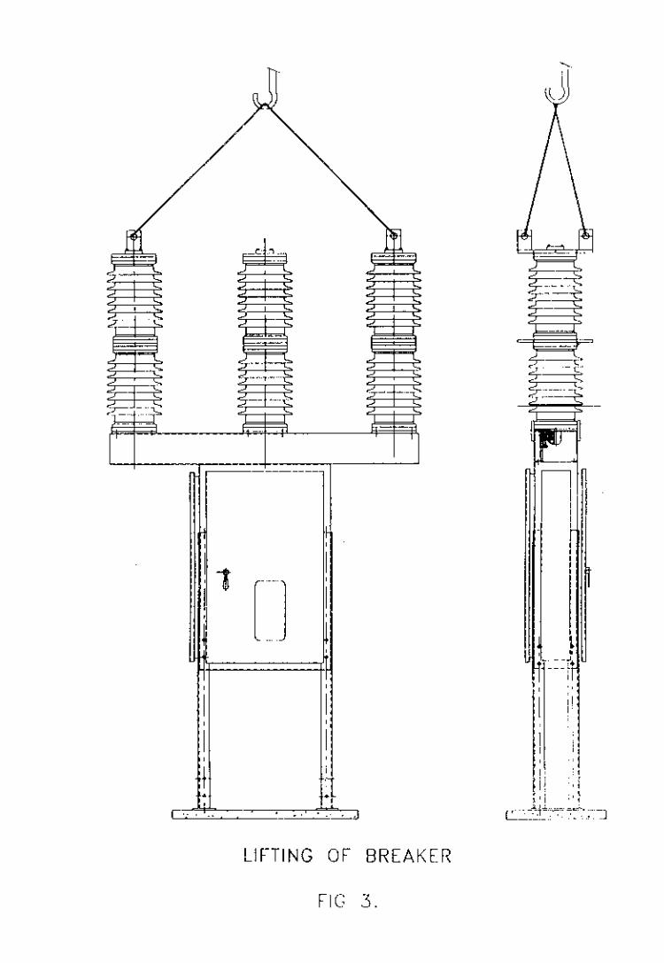
-It is recommended to use standard tools and standard practices for lifting and transport of the
circuit breakers at the time of erection, so as to avoid mechanical damages of the pole parts.
In general the lifting of the circuit breaker shall be done as shown in fig. 3.
4.1.1. Preparations :
To be made available are ...
- An erection crane with a load carrying capacity of about 1000 Kg and a crane hook height of
at least 4 m ( = 13 ft.) above the floor.
- Lifting ropes
- Dimension drawing, erection drawings, wiring and circuit diagrams.
- Torque wrench for a range of 6 - 100 NM.
- Circlip plier
- . Commercially available set of open end 8 ring spanners size from 7 mm. to 43 mm.
- Cleaning and working materials like cloths etc.
- Conducting grease
- Spirit level
4.2 Erection Procedure :
- Attach consignment unit breaker assembly with crane using the hooks (ref. Fig. 3 ).
- Place the support plate of the mvunting structure leg assembly on the prepared foundation.
Tighten the structure with the foundation bolts with specified hardware. (ref. fig. 1 )
- The exact location and the method of foundation can be obtained from the installation
layout plan or a general arrangement drawing. (Fig. 1 )
4
4.2.1 Adjustment of control cubicle and spring mechanism cabinet.
The complete circuit breaker with control cabinet has adjustment provision to maintain a
maximum ground clearance upto 3860 mm in a slot of every 100 mm. Depending on the site
requirements of Incoming and Outgoing cable, the height of the pole terminals can be adjusted
suitably as shown in GA drawing.
- Once the height is adjusted, the fasteners shall be tightened to achieve the required ground
clearance & clearances between phases.
- Ensure the level of the breaker by spirit level.
4.3 High voltage connection : (Fig. 1 )
The high voltage connection fasteners shall be preferably of M 12 size stainless steel bolt and
nut and at least 1 washer and i spring washer.
Terminal connectors (Aa - Fig. 1 ) should be properly cleaned using SS Wire brush to remove
the aluminium oxide film and conducting grease to be applied.
The cable terminals shall be connected in such a fashion that the clearance are maintained
properly.
4.4 Low voltage connections :
The auxiliary circuit connection shall be checked as per the relevant schematic diagram for
correctness. (See fig. 2 for typical schematic). A removable gland plate is provided in the bottom
of control cable (Ls - Fig. 1 ) which can be suitably drilled as per control cable glands.
5. Commissioning
All the data / parameters which are checked or measured shall be entered in a commissioning
record and kept for later comparison. The final trial switching operations shall be carried out on
fully erected circuit breaker, isolated from the high voltage system and earthed according to the
regulations.
Once the auxiliary circuit is connected to the low voltage system, the spring charging motor get
a supply and the motor starts charging the spring. As the spring is charged completely,
automatically the motor supply will get cut off and the breaker is ready for closing operation.
The closing and opening operations, then can be performed as explained in paint 3.2.2 and
point 3.3.3..
Space Heaters :
One Space Heater is provided in the control cabinet. The heater switch must be always "ON",
when the breakers are in service to prevent condensation.
(5)
6. Checking the Vacuum
Before putting the breaker in service, or if any interrupter is suspected for leakage, vacuum
should be checked. The best way to check vacuum if to conduct high voltage test. ( 56kV,
1 Min.) Across the open contact of circuit breakers. If HV test kit is not available, then the
following procedure shall be followed.
1. Put the circuit breaker off.
2. Isolate the circuit breaker from high voltage connections.
3. Earth the circuit breaker.
4. Disconnect auxiliary supply.
5. Discharge the springs manually.
6. Visually inspect the circuit breaker and carry out further maintenance.
Remove the bottom covers & side covers of the duct ( Refer fig.l1 ) Remove the circlip from
the pin used for connecting the linkage system (links 6,7 and 8 ) of each pole. When the pin is
removed, the actuating rod will be suddenly pulled up due to the vacuum in the healthy
interrupter.
6.1 Dielectric Test :
Prior to commissioning the breaker or putting it back into service after a maintenance outage,
the circuit breaker should be checked for insulation resistance for following configurations
using a 5kV meggar kit.
1. CB open, between phase terminals (2 readings)
2. CB open, between top terminals and earth (3 readings) and
3. CB closed between terminals and earth (3 readings)
(6)
7. MAINTENANCE
7.1 Caution :
Before carrying out any maintenance work it is essential to follow the procedures given below :
· Open the circuit breaker and check that both opening and closing springs are discharged.
·
7.2 General features :
During normal service the circuit breaker require only limited maintenance. The frequency -
and the sort of inspection and maintenance basically depend on the service conditions.
Various factors must be taken into account e.g. frequency of operations, interrupted current
values and relative power factor as well as the installation ambient.
The following table gives the maintenance schedule showing the relative time intervals between
maintenance work. As far as the time interval between these operations is concerned, it is
advisable to comply with specification given in the table.
On the basis of the results obtained during the periodic inspection, it is possible to set the
optimal time limits for carrying out maintenance work.
These rules should also be followed :
Any circuit breaker which will only operate a few times or which will remain closed (ON) or open
(OFF) for long periods, should be operated from time to time to prevent clogging which may
cause a reduction in the closing or opening speed.
When the circuit breaker is in service it should be visually inspected to detect any dust, dirt or
damage of any kind.
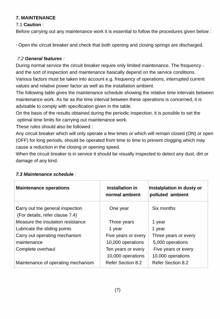
7.3 Maintenance schedule :
Maintenance operations Installation in Instalplation in dusty or
normal ambient polluted ambient
Carry out tne general inspection One year Six months
(For details, refer clause 7.4)
Measure the insulation resistance Three years 1 year
Lubricate the sliding points 1 year 1 year
Carry out operating mechanism Five years or every Three years or every
maintenance 10,000 operations 5,000 operations
Complete overhaul Ten years or every Five years or every
10,000 operations 10,000 operations
Maintenance of operating mechanism Refer Section 8.2 Refer Section 8.2
(7)
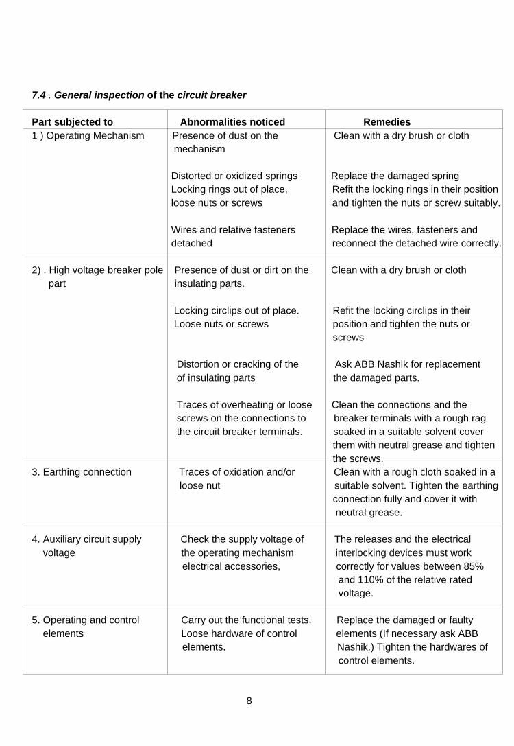
7.4 . General inspection of the circuit breaker
Part subjected to Abnormalities noticed Remedies
1 ) Operating Mechanism Presence of dust on the Clean with a dry brush or cloth
mechanism
Distorted or oxidized springs Replace the damaged spring
Locking rings out of place, Refit the locking rings in their position
loose nuts or screws and tighten the nuts or screw suitably.
Wires and relative fasteners Replace the wires, fasteners and
detached reconnect the detached wire correctly.
2) . High voltage breaker pole Presence of dust or dirt on the Clean with a dry brush or cloth
part insulating parts.
Locking circlips out of place. Refit the locking circlips in their
Loose nuts or screws position and tighten the nuts or
screws
Distortion or cracking of the Ask ABB Nashik for replacement
of insulating parts the damaged parts.
Traces of overheating or loose Clean the connections and the
screws on the connections to breaker terminals with a rough rag
the circuit breaker terminals. soaked in a suitable solvent cover
them with neutral grease and tighten
the screws.
3. Earthing connection Traces of oxidation and/or Clean with a rough cloth soaked in a
loose nut suitable solvent. Tighten the earthing
connection fully and cover it with
neutral grease.
4. Auxiliary circuit supply Check the supply voltage of The releases and the electrical
voltage the operating mechanism interlocking devices must work
electrical accessories, correctly for values between 85%
and 110% of the relative rated
voltage.
5. Operating and control Carry out the functional tests. Replace the damaged or faulty
elements Loose hardware of control elements (If necessary ask ABB
elements. Nashik.) Tighten the hardwares of
control elements.
8
8. Operating Mechanism
The operating mechanism has a spring charging device which can be operated by motor or by hand.
The operating device has compression spring for closing and tension springs for opening. The opening
spring is charged automatically when the breaker is closed . A closed breaker with charged closing
spring can be operated OPEN - CLOSE - OPEN without intermediate motorised or manual charging
and the breaker can therefore be used
for auto re-closing. Charging of the closing spring can be stopped by disconnecting the voltage to the
motor and manually operate the breaker CLOSE - OPEN.
An indication shows whether the closing spring is charged or not and the number of opening operations
are recorded on a counter.
The motor can be supplied via .a station battery, a network or via a transformer with a limit load of at
least 500 VA. The motor starts after each closing operation and charges the closing springs within 15
seconds.
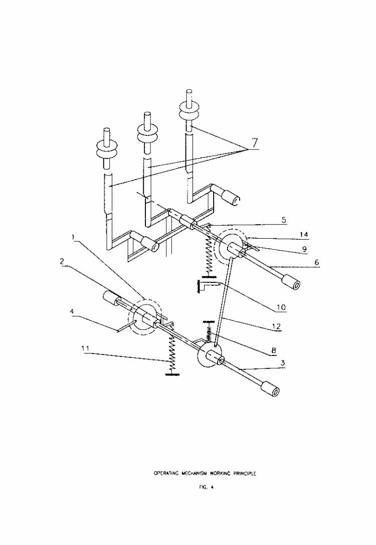
The construction of the operating mechanism is shown in figure 4. The device has two shafts. The top
shaft (6) is connected to the breaker poles via links and is directly actuated by the openings springs (5).
The bottom shaft (3) is connected directly to the closing spring (11). These two shafts are linked via the
driving disc (9) and the link (12), and by the trip free device (14). The bottom shaft is also connected to
the charging device via the trip-free device (1 ) and the link (4).
The latching & trip free devices (1 )and (14) are of the same type that have been used in ABB
equipment since 1950 and have proven extremely reliable .
The motor operated unit consists of a toothed transmission gear with an eccentricity driven tooth wheel
as a last step. The operating device is also mounted with auxiliary contacts and trip coils.
9
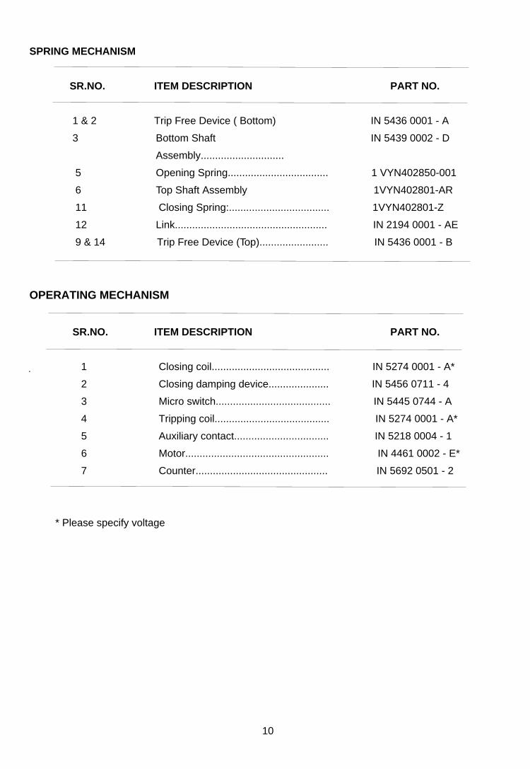
SPRING MECHANISM
SR.NO. ITEM DESCRIPTION PART NO.
1 & 2 Trip Free Device ( Bottom) IN 5436 0001 - A
3 Bottom Shaft IN 5439 0002 - D
Assembly.............................
5 Opening Spring................................... 1 VYN402850-001
6 Top Shaft Assembly 1VYN402801-AR
11 Closing Spring:................................... 1VYN402801-Z
12 Link..................................................... IN 2194 0001 - AE
9 & 14 Trip Free Device (Top)........................ IN 5436 0001 - B
OPERATING MECHANISM
SR.NO. ITEM DESCRIPTION PART NO.
1 Closing coil......................................... IN 5274 0001 - A*
2 Closing damping device..................... IN 5456 0711 - 4
3 Micro switch........................................ IN 5445 0744 - A
4 Tripping coil........................................ IN 5274 0001 - A*
5 Auxiliary contact................................. IN 5218 0004 - 1
6 Motor.................................................. IN 4461 0002 - E*
7 Counter.............................................. IN 5692 0501 - 2
* Please specify voltage
10
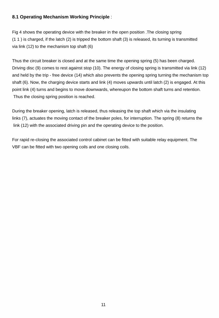
8.1 Operating Mechanism Working Principle :
Fig 4 shows the operating device with the breaker in the open position .The closing spring
(1 1 ) is charged, if the latch (2) is tripped the bottom shaft (3) is released, its turning is transmitted
via link (12) to the mechanism top shaft (6)
Thus the circuit breaker is closed and at the same time the opening spring (5) has been charged.
Driving disc (9) comes to rest against stop (10). The energy of closing spring is transmitted via link (12)
and held by the trip - free device (14) which also prevents the opening spring turning the mechanism top
shaft (6). Now, the charging device starts and link (4) moves upwards until latch (2) is engaged. At this
point link (4) turns and begins to move downwards, whereupon the bottom shaft turns and retention.
Thus the closing spring position is reached.
During the breaker opening, latch is released, thus releasing the top shaft which via the insulating
links (7), actuates the moving contact of the breaker poles, for interruption. The spring (8) returns the
link (12) with the associated driving pin and the operating device to the position.
For rapid re-closing the associated control cabinet can be fitted with suitable relay equipment. The
VBF can be fitted with two opening coils and one closing coils.
11
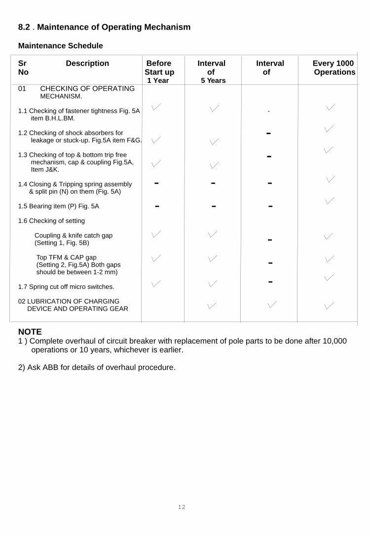
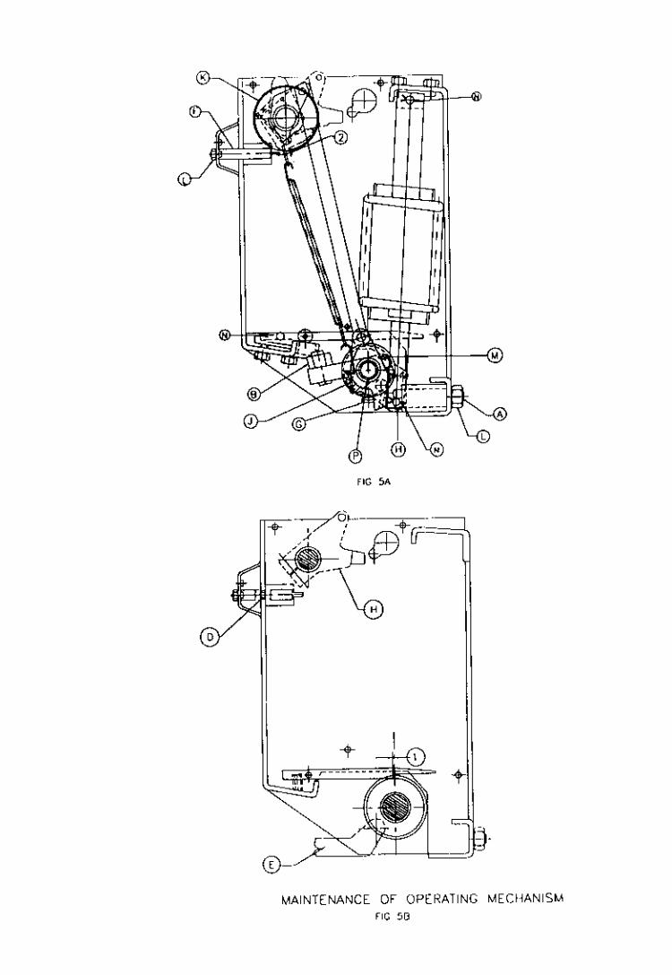
8.2 . Maintenance of Operating Mechanism
Maintenance Schedule
Sr Description Before Interval Interval Every 1000 No Start up of of Operations 1 Year 5 Years01 CHECKING OF OPERATING MECHANISM.
1.1 Checking of fastener tightness Fig. 5A - item B.H.L.BM.
1.2 Checking of shock absorbers for - leakage or stuck-up. Fig.5A item F&G.
1.3 Checking of top & bottom trip free mechanism, cap & coupling Fig.5A, Item J&K.
1.4 Closing & Tripping spring assembly & split pin (N) on them (Fig. 5A)
1.5 Bearing item (P) Fig. 5A
1.6 Checking of setting
Coupling & knife catch gap (Setting 1, Fig. 5B) Top TFM & CAP gap (Setting 2, Fig.5A) Both gaps should be between 1-2 mm)
1.7 Spring cut off micro switches.
02 LUBRICATION OF CHARGING DEVICE AND OPERATING GEAR
NOTE1 ) Complete overhaul of circuit breaker with replacement of pole parts to be done after 10,000 operations or 10 years, whichever is earlier.
2) Ask ABB for details of overhaul procedure.
12
-
-
-
-
-
-
-
-
-
-
-
--
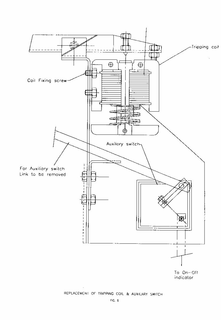
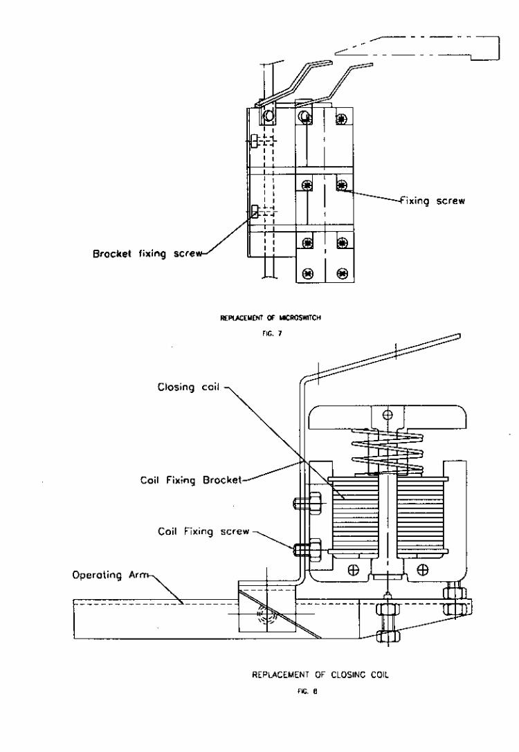
8.3 Replacement of Operating Coils
Refer. Fig.6 & 8 which Indicates the mounting arrangement for closing coil and the tripping coil and
auxiliary switch.
8.4 Replacement of Microswitch (Fig.7)
Microswitch is mounted on a circuit breaker frame and likely to get distributed. Theframe is
provided with slots vertically and the microswitch can be adjusted vertically. After the adjustment
of the microswitch, screws of the fixing bracket shall be fasten correctly.
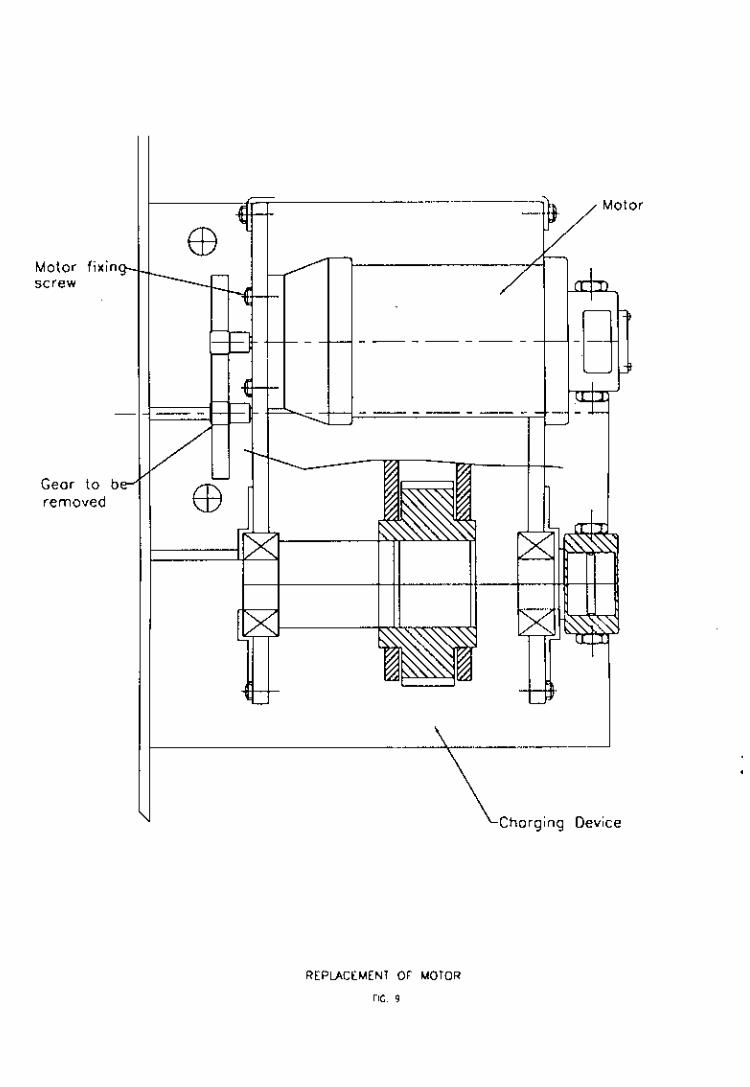
8.5 Replacement of Motor
Refer. Fig.9. for replacement of motor. The figure is self explanatory. The motor is mounted on spring
charging device, with the help of screws.
8.6 Breaker Pole :
ABB 36kV Outdoor Circuit Breaker type VBF is developed using a well proven vacuum interrupters,
excellent arc quenching and insulating properties of vacuum offer long reliable service.
The construction of the pole of this breaker is very simple and has very less number of moving parts, so the
operating energy level is very low, thus requires a very low maintenance. However, assembly of a pole at site may
be required for replacement of vacuum interrupter.
Construction & Assembly of a Pole :
- Fig. No. 10 shows the complete assembly of a pole.
Assembly of pole can be done as follows :
The crank housing assembly consists of a crank housing (1 ). Clean and degrease the sealing surface
and sealing ring grooves. Mount damper and lock it (2) with a circlip. Now push the bearing (3) in the
bearing seat provided inside the crank housing. Fix the bearing (4) on the other side of crank housing.
Then insert a spacer (5). Insert the seal (6) duly with grease Syntheso PROAA2.
13
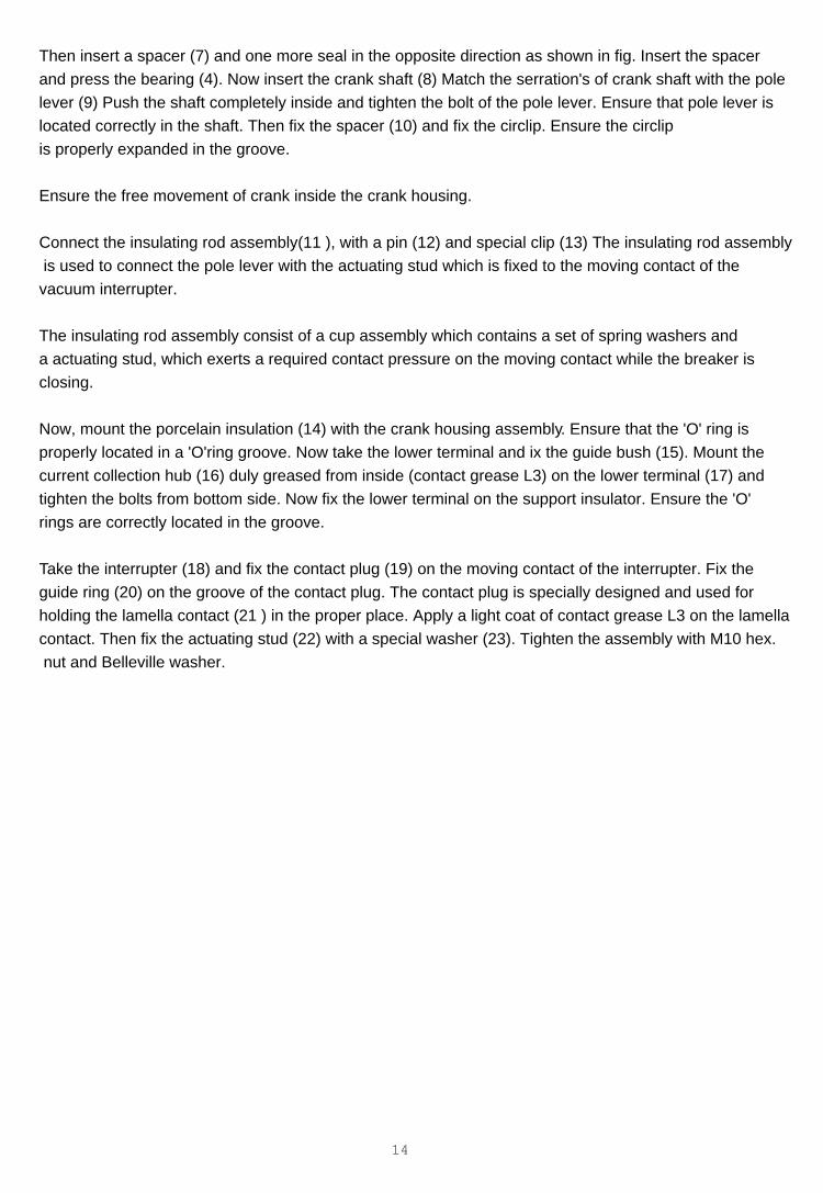
Then insert a spacer (7) and one more seal in the opposite direction as shown in fig. Insert the spacer
and press the bearing (4). Now insert the crank shaft (8) Match the serration's of crank shaft with the pole
lever (9) Push the shaft completely inside and tighten the bolt of the pole lever. Ensure that pole lever is
located correctly in the shaft. Then fix the spacer (10) and fix the circlip. Ensure the circlip
is properly expanded in the groove.
Ensure the free movement of crank inside the crank housing.
Connect the insulating rod assembly(11 ), with a pin (12) and special clip (13) The insulating rod assembly
is used to connect the pole lever with the actuating stud which is fixed to the moving contact of the
vacuum interrupter.
The insulating rod assembly consist of a cup assembly which contains a set of spring washers and
a actuating stud, which exerts a required contact pressure on the moving contact while the breaker is
closing.
Now, mount the porcelain insulation (14) with the crank housing assembly. Ensure that the 'O' ring is
properly located in a 'O'ring groove. Now take the lower terminal and ix the guide bush (15). Mount the
current collection hub (16) duly greased from inside (contact grease L3) on the lower terminal (17) and
tighten the bolts from bottom side. Now fix the lower terminal on the support insulator. Ensure the 'O'
rings are correctly located in the groove.
Take the interrupter (18) and fix the contact plug (19) on the moving contact of the interrupter. Fix the
guide ring (20) on the groove of the contact plug. The contact plug is specially designed and used for
holding the lamella contact (21 ) in the proper place. Apply a light coat of contact grease L3 on the lamella
contact. Then fix the actuating stud (22) with a special washer (23). Tighten the assembly with M10 hex.
nut and Belleville washer.
14
Caution :
While fixing the contact plug and actuating stud, vacuum interrupter shall be protected from twisting
movement, which may damage the sealing bellows of the vacuum interrupter.
Insert this interrupter assembly in the collector collection hub and match the hole of the actuating stud
and the insulating rod. Insert the special pin (24) and fix the split pin. Now mount the upper insulator
and fix it with the lower terminal plate. Fix the 'O' ring in the upper terminal and then locate the upper
terminal (24) on the insulator body. Secure the vacuum interrupter with the upper terminal and fix the
bolt. Before tightening the upper bolt take few manual operations by fixing the inter pole lever (27) for
R&B pole and for Y pole composite lever (28) .
Ensure the free movement of the contact and then tighten the bolt of vacuum interrupter with a torque
of 90 NM. Fix the sealing cover with a sealing 'O'ring and tighten the hardware. Fasten the hardware
of inter pole lever and composite lever. This completes the pole assembly.
15
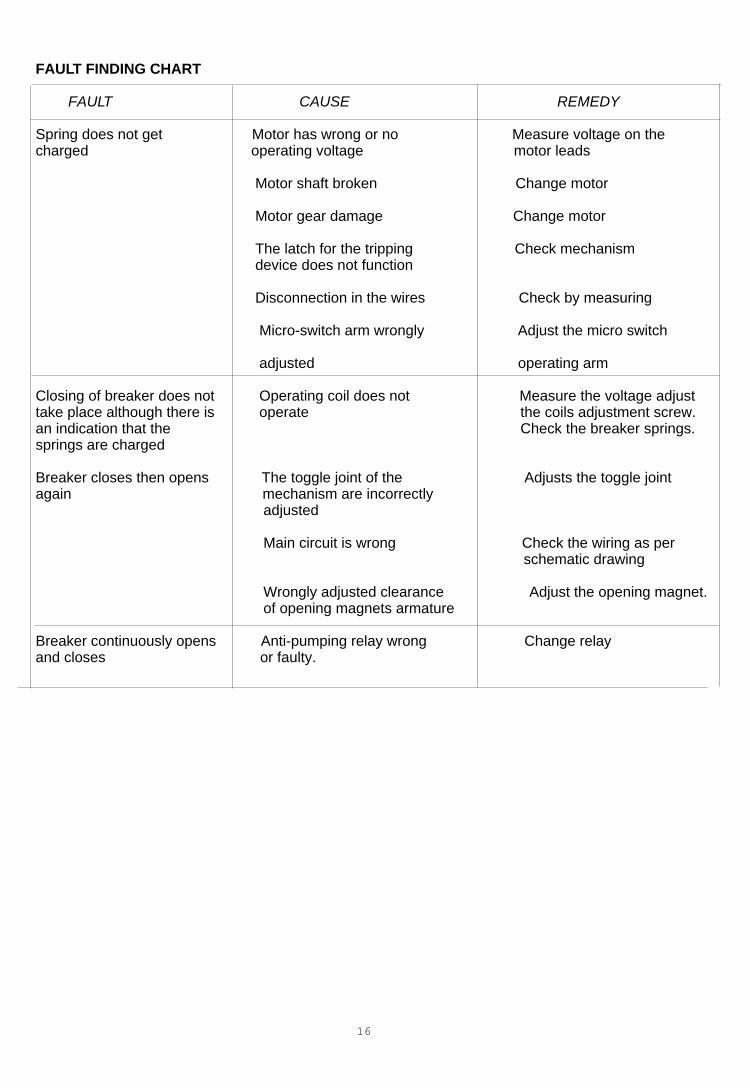
FAULT FINDING CHART
FAULT CAUSE REMEDY
Spring does not get Motor has wrong or no Measure voltage on the charged operating voltage motor leads
Motor shaft broken Change motor Motor gear damage Change motor The latch for the tripping Check mechanism device does not function
Disconnection in the wires Check by measuring Micro-switch arm wrongly Adjust the micro switch adjusted operating arm
Closing of breaker does not Operating coil does not Measure the voltage adjust take place although there is operate the coils adjustment screw. an indication that the Check the breaker springs. springs are charged
Breaker closes then opens The toggle joint of the Adjusts the toggle joint again mechanism are incorrectly adjusted
Main circuit is wrong Check the wiring as per schematic drawing
Wrongly adjusted clearance Adjust the opening magnet. of opening magnets armature
Breaker continuously opens Anti-pumping relay wrong Change relay and closes or faulty.
16
LIST OF DRAWINGS
Fig. 1 : Circuit Breaker GA Drawing
Fig. 2 : Schematic circuit diagram.
Fig. 3 : Lifting of Breaker
Fig. 4 : Operating Principle of Circuit Breaker
Fig. 5 : Maintenance of Mechanism Fig.5A / 5B
Fig. 6 : Replacement of tripping coil
Fig. 7 : Replacement of microswitch
Fig.8 : Replacement of closing coil
Fig. 9 : Replacement of motor
Fig. 10 : Breaker Pole Assembly
Fig. 11 : Breaker Assembly
17

No liability is accepted for the accuracy of the information contained in this publication. We reserve the right to make amendments in the courseof technical progress.
1V
DU
28
00
1-Y
N
Asea Brown Boveri LimitedPlot No 79, Street No 17MIDC Estate, SatpurNashik - 422 007Telephone: (0253) - 351095/96/97/98 : (0253) - 351261/62/63/64Telex : (0752) -288/389 ABBN INTelefax : (1253) - 350644 / 351249Gram : ABBFILIAL