Embed Size (px)
Citation preview
9
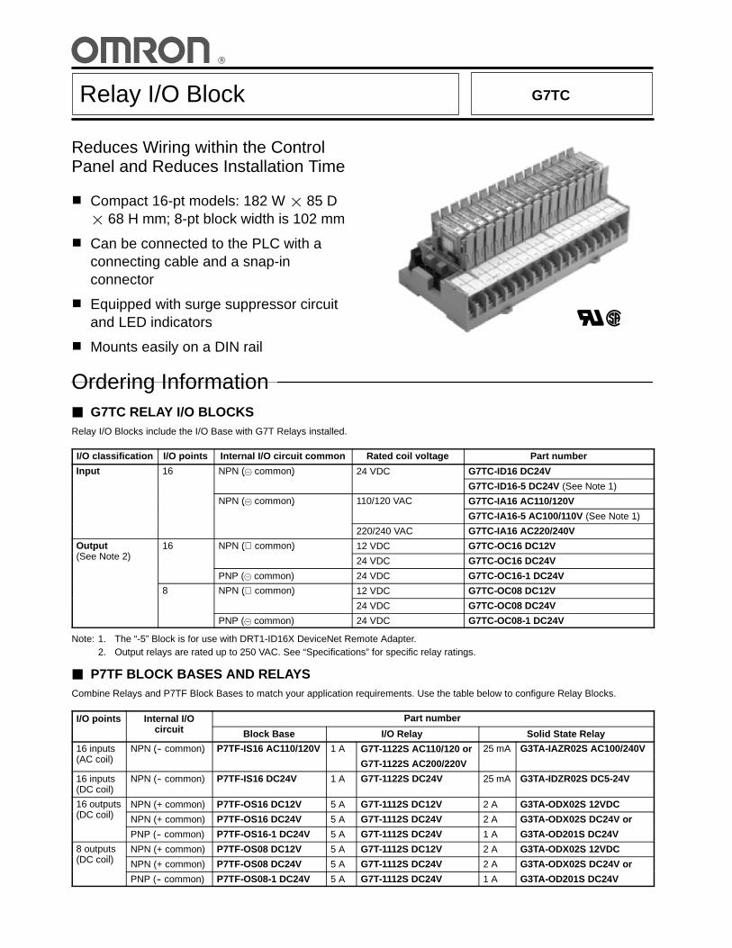
Relay I/O Block G7TC
Reduces Wiring within the ControlPanel and Reduces Installation Time
1 Compact 16-pt models: 182 W l 85 Dl 68 H mm; 8-pt block width is 102 mm
1 Can be connected to the PLC with aconnecting cable and a snap-inconnector
1 Equipped with surge suppressor circuitand LED indicators
1 Mounts easily on a DIN rail
èò
Ordering Information3 G7TC RELAY I/O BLOCKSRelay I/O Blocks include the I/O Base with G7T Relays installed.
I/O classification I/O points Internal I/O circuit common Rated coil voltage Part number
Input 16 NPN ( common) 24 VDC G7TC-ID16 DC24Vp ( )
G7TC-ID16-5 DC24V (See Note 1)
NPN ( common) 110/120 VAC G7TC-IA16 AC110/120V( )
G7TC-IA16-5 AC100/110V (See Note 1)
220/240 VAC G7TC-IA16 AC220/240V
Output(S N t 2)
16 NPN (⊕ common) 12 VDC G7TC-OC16 DC12Vp(See Note 2)
( )
24 VDC G7TC-OC16 DC24V
PNP ( common) 24 VDC G7TC-OC16-1 DC24V
8 NPN (⊕ common) 12 VDC G7TC-OC08 DC12V( )
24 VDC G7TC-OC08 DC24V
PNP ( common) 24 VDC G7TC-OC08-1 DC24V
Note: 1. The “-5” Block is for use with DRT1-ID16X DeviceNet Remote Adapter.2. Output relays are rated up to 250 VAC. See “Specifications” for specific relay ratings.
3 P7TF BLOCK BASES AND RELAYSCombine Relays and P7TF Block Bases to match your application requirements. Use the table below to configure Relay Blocks.
I/O points Internal I/Oi it
Part numberpcircuit Block Base I/O Relay Solid State Relay
16 inputs(AC il)
NPN (-- common) P7TF-IS16 AC110/120V 1 A G7T-1122S AC110/120 or 25 mA G3TA-IAZR02S AC100/240V(AC coil)
( )
G7T-1122S AC200/220V
16 inputs(DC coil)
NPN (-- common) P7TF-IS16 DC24V 1 A G7T-1122S DC24V 25 mA G3TA-IDZR02S DC5-24V
16 outputs(DC il)
NPN (+ common) P7TF-OS16 DC12V 5 A G7T-1112S DC12V 2 A G3TA-ODX02S 12VDC(DC coil) NPN (+ common) P7TF-OS16 DC24V 5 A G7T-1112S DC24V 2 A G3TA-ODX02S DC24V or
PNP (-- common) P7TF-OS16-1 DC24V 5 A G7T-1112S DC24V 1 A G3TA-OD201S DC24V
8 outputs(DC il)
NPN (+ common) P7TF-OS08 DC12V 5 A G7T-1112S DC12V 2 A G3TA-ODX02S 12VDC(DC coil) NPN (+ common) P7TF-OS08 DC24V 5 A G7T-1112S DC24V 2 A G3TA-ODX02S DC24V or
PNP (-- common) P7TF-OS08-1 DC24V 5 A G7T-1112S DC24V 1 A G3TA-OD201S DC24V
G7TC G7TC
2
1. Input/Output ClassificationI : For input
O: For output
2. Type of I/O SignalA : AC coil type for input relays mountedD : DC coil type for input relays mountedC : Contact output
3. Number of I/O Points16: 16 points08: 8 points (for output only)
4. Internal I/O Circuit CommonBlank:NPN (+) common1: PNP (--) common5. Block for use with DeviceNet
G7TC- -
1 2 3 4
1. Input/Output ClassificationI : For input
O: For output
2. Type of I/O SignalS : Socket for input or output relays
3. Number of I/O Points16: 16 points08: 8 points (for output only)
4. Internal I/O Circuit CommonBlank: NPN (+) common1: PNP (--) common
P7TF- -
1 2 3 4
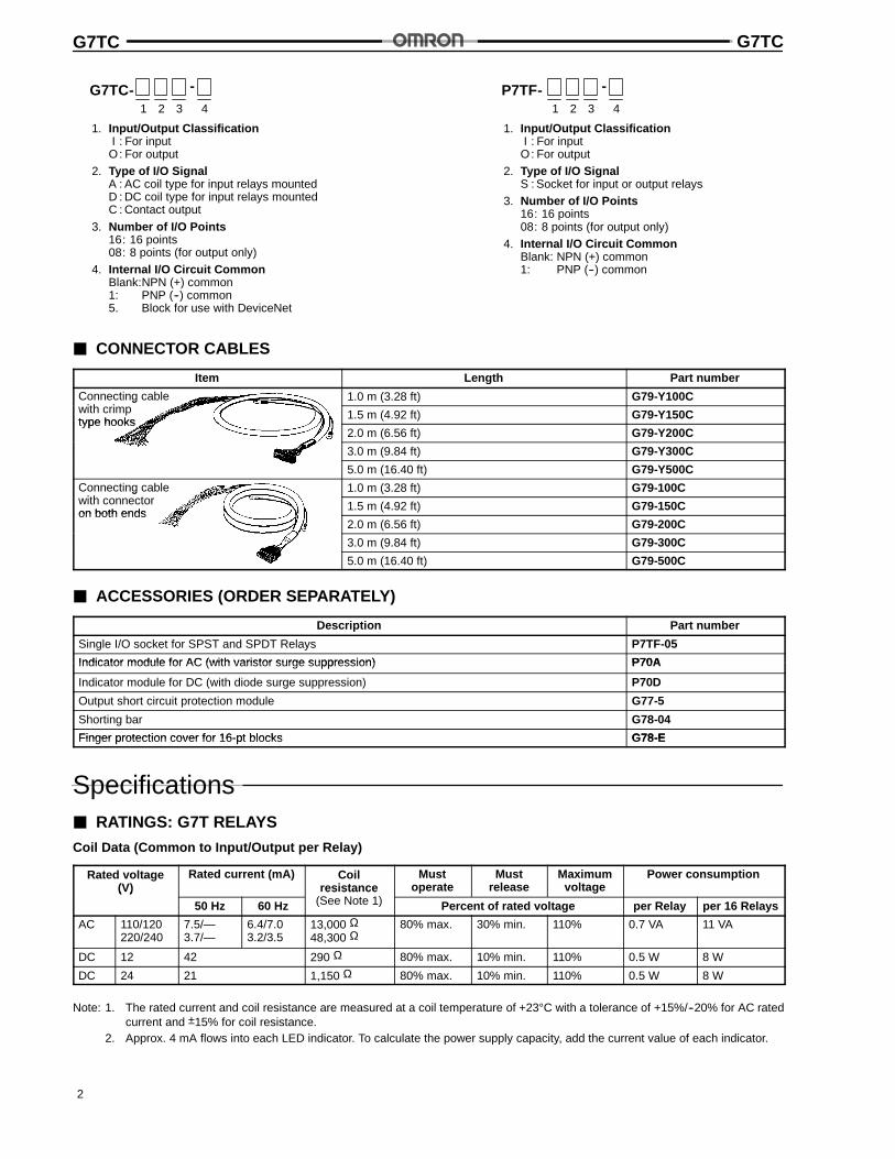
3 CONNECTOR CABLES
Item Length Part number
Connecting cableith i
1.0 m (3.28 ft) G79-Y100Cgwith crimptype hooks
1.5 m (4.92 ft) G79-Y150Ctype hooks
2.0 m (6.56 ft) G79-Y200C
3.0 m (9.84 ft) G79-Y300C
5.0 m (16.40 ft) G79-Y500C
Connecting cableith t
1.0 m (3.28 ft) G79-100Cgwith connectoron both ends
1.5 m (4.92 ft) G79-150Con both ends
2.0 m (6.56 ft) G79-200C
3.0 m (9.84 ft) G79-300C
5.0 m (16.40 ft) G79-500C
3 ACCESSORIES (ORDER SEPARATELY)
Description Part number
Single I/O socket for SPST and SPDT Relays P7TF-05
Indicator module for AC (with varistor surge suppression) P70AIndicator module for AC (with varistor surge suppression) P70A
Indicator module for DC (with diode surge suppression) P70D
Output short circuit protection module G77-5
Shorting bar G78-04
Finger protection cover for 16-pt blocks G78-EFinger protection cover for 16-pt blocks G78-E
Specifications3 RATINGS: G7T RELAYS
Coil Data (Common to Input/Output per Relay)
Rated voltage(V)
Rated current (mA) Coilresistance
(S N 1)
Mustoperate
Mustrelease
Maximumvoltage
Power consumption( )
50 Hz 60 Hz
es sta ce(See Note 1) Percent of rated voltage per Relay per 16 Relays
AC 110/120220/240
7.5/—3.7/—
6.4/7.03.2/3.5
13,000 Ω48,300 Ω
80% max. 30% min. 110% 0.7 VA 11 VA
DC 12 42 290 Ω 80% max. 10% min. 110% 0.5 W 8 W
DC 24 21 1,150 Ω 80% max. 10% min. 110% 0.5 W 8 W
Note: 1. The rated current and coil resistance are measured at a coil temperature of +23°C with a tolerance of +15%/--20% for AC ratedcurrent and ±15% for coil resistance.
2. Approx. 4 mA flows into each LED indicator. To calculate the power supply capacity, add the current value of each indicator.
G7TC G7TC
3
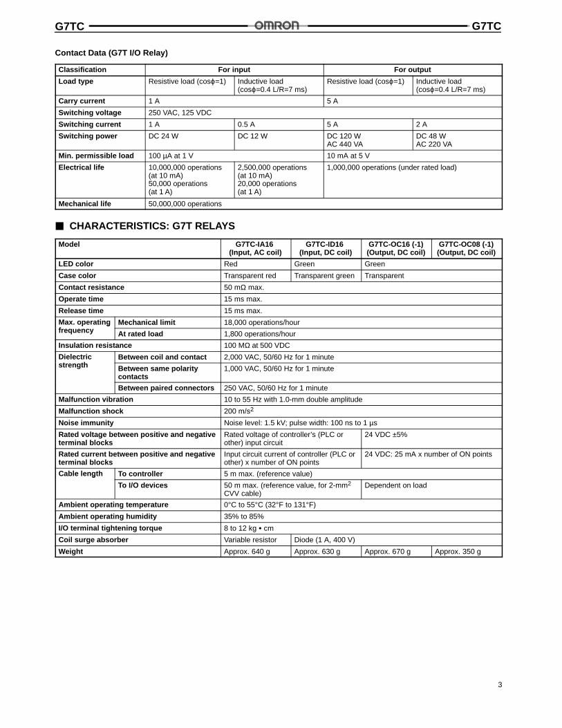
Contact Data (G7T I/O Relay)
Classification For input For output
Load type Resistive load (cosϕ=1) Inductive load(cosϕ=0.4 L/R=7 ms)
Resistive load (cosϕ=1) Inductive load(cosϕ=0.4 L/R=7 ms)
Carry current 1 A 5 A
Switching voltage 250 VAC, 125 VDC
Switching current 1 A 0.5 A 5 A 2 A
Switching power DC 24 W DC 12 W DC 120 WAC 440 VA
DC 48 WAC 220 VA
Min. permissible load 100 µA at 1 V 10 mA at 5 V
Electrical life 10,000,000 operations(at 10 mA)50,000 operations(at 1 A)
2,500,000 operations(at 10 mA)20,000 operations(at 1 A)
1,000,000 operations (under rated load)
Mechanical life 50,000,000 operations
3 CHARACTERISTICS: G7T RELAYS
Model G7TC-IA16(Input, AC coil)
G7TC-ID16(Input, DC coil)
G7TC-OC16 (-1)(Output, DC coil)
G7TC-OC08 (-1)(Output, DC coil)
LED color Red Green Green
Case color Transparent red Transparent green Transparent
Contact resistance 50 mΩ max.
Operate time 15 ms max.
Release time 15 ms max.
Max. operatingf
Mechanical limit 18,000 operations/hourp gfrequency At rated load 1,800 operations/hour
Insulation resistance 100 MΩ at 500 VDC
Dielectrict th
Between coil and contact 2,000 VAC, 50/60 Hz for 1 minutestrength Between same polarity
contacts1,000 VAC, 50/60 Hz for 1 minute
Between paired connectors 250 VAC, 50/60 Hz for 1 minute
Malfunction vibration 10 to 55 Hz with 1.0-mm double amplitude
Malfunction shock 200 m/s2
Noise immunity Noise level: 1.5 kV; pulse width: 100 ns to 1 µs
Rated voltage between positive and negativeterminal blocks
Rated voltage of controller’s (PLC orother) input circuit
24 VDC ±5%
Rated current between positive and negativeterminal blocks
Input circuit current of controller (PLC orother) x number of ON points
24 VDC: 25 mA x number of ON points
Cable length To controller 5 m max. (reference value)g
To I/O devices 50 m max. (reference value, for 2-mm2
CVV cable)Dependent on load
Ambient operating temperature 0°C to 55°C (32°F to 131°F)
Ambient operating humidity 35% to 85%
I/O terminal tightening torque 8 to 12 kg : cm
Coil surge absorber Variable resistor Diode (1 A, 400 V)
Weight Approx. 640 g Approx. 630 g Approx. 670 g Approx. 350 g
G7TC G7TC
4
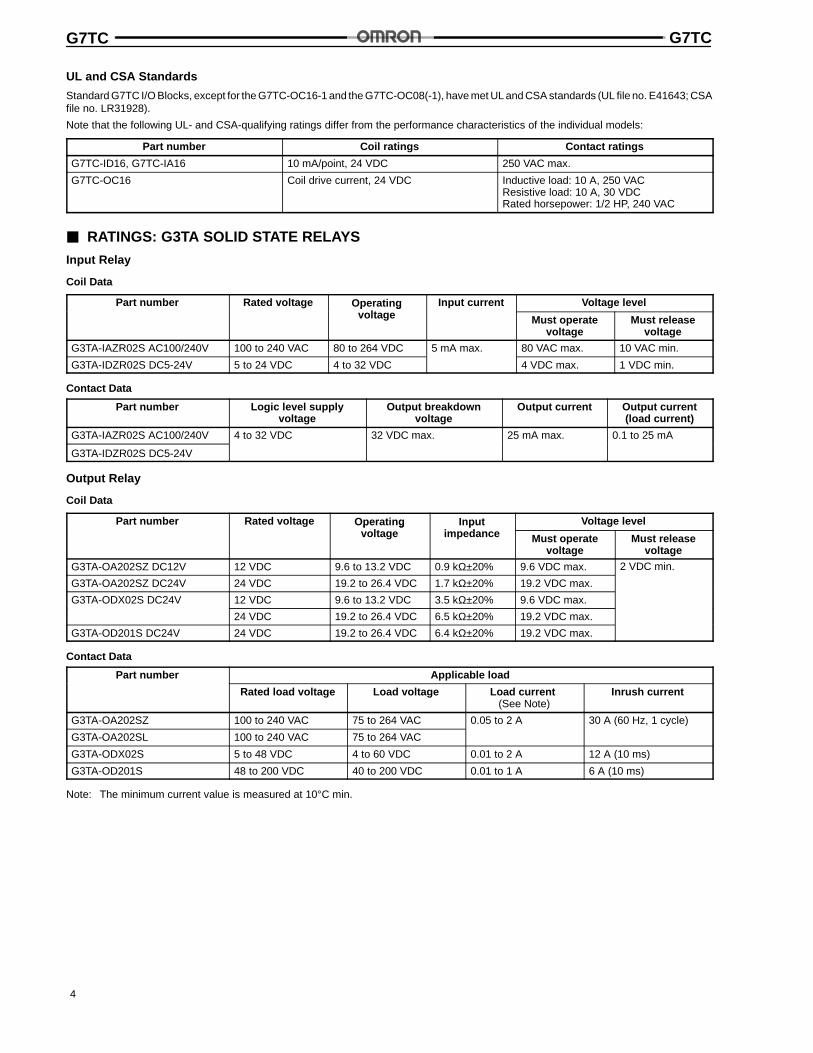
UL and CSA Standards
Standard G7TC I/O Blocks, except for the G7TC-OC16-1 and the G7TC-OC08(-1), have met UL and CSA standards (UL file no. E41643; CSAfile no. LR31928).
Note that the following UL- and CSA-qualifying ratings differ from the performance characteristics of the individual models:
Part number Coil ratings Contact ratings
G7TC-ID16, G7TC-IA16 10 mA/point, 24 VDC 250 VAC max.
G7TC-OC16 Coil drive current, 24 VDC Inductive load: 10 A, 250 VACResistive load: 10 A, 30 VDCRated horsepower: 1/2 HP, 240 VAC
3 RATINGS: G3TA SOLID STATE RELAYS
Input Relay
Coil Data
Part number Rated voltage Operatinglt
Input current Voltage levelp gvoltage Must operate
voltageMust release
voltage
G3TA-IAZR02S AC100/240V 100 to 240 VAC 80 to 264 VDC 5 mA max. 80 VAC max. 10 VAC min.
G3TA-IDZR02S DC5-24V 5 to 24 VDC 4 to 32 VDC 4 VDC max. 1 VDC min.
Contact Data
Part number Logic level supplyvoltage
Output breakdownvoltage
Output current Output current(load current)
G3TA-IAZR02S AC100/240V 4 to 32 VDC 32 VDC max. 25 mA max. 0.1 to 25 mA
G3TA-IDZR02S DC5-24V
Output Relay
Coil Data
Part number Rated voltage Operatinglt
Inputi d
Voltage levelp gvoltage
pimpedance Must operate
voltageMust release
voltage
G3TA-OA202SZ DC12V 12 VDC 9.6 to 13.2 VDC 0.9 kΩ±20% 9.6 VDC max. 2 VDC min.
G3TA-OA202SZ DC24V 24 VDC 19.2 to 26.4 VDC 1.7 kΩ±20% 19.2 VDC max.
G3TA-ODX02S DC24V 12 VDC 9.6 to 13.2 VDC 3.5 kΩ±20% 9.6 VDC max.
24 VDC 19.2 to 26.4 VDC 6.5 kΩ±20% 19.2 VDC max.
G3TA-OD201S DC24V 24 VDC 19.2 to 26.4 VDC 6.4 kΩ±20% 19.2 VDC max.
Contact Data
Part number Applicable load
Rated load voltage Load voltage Load current(See Note)
Inrush current
G3TA-OA202SZ 100 to 240 VAC 75 to 264 VAC 0.05 to 2 A 30 A (60 Hz, 1 cycle)
G3TA-OA202SL 100 to 240 VAC 75 to 264 VAC
G3TA-ODX02S 5 to 48 VDC 4 to 60 VDC 0.01 to 2 A 12 A (10 ms)
G3TA-OD201S 48 to 200 VDC 40 to 200 VDC 0.01 to 1 A 6 A (10 ms)
Note: The minimum current value is measured at 10°C min.
G7TC G7TC
5
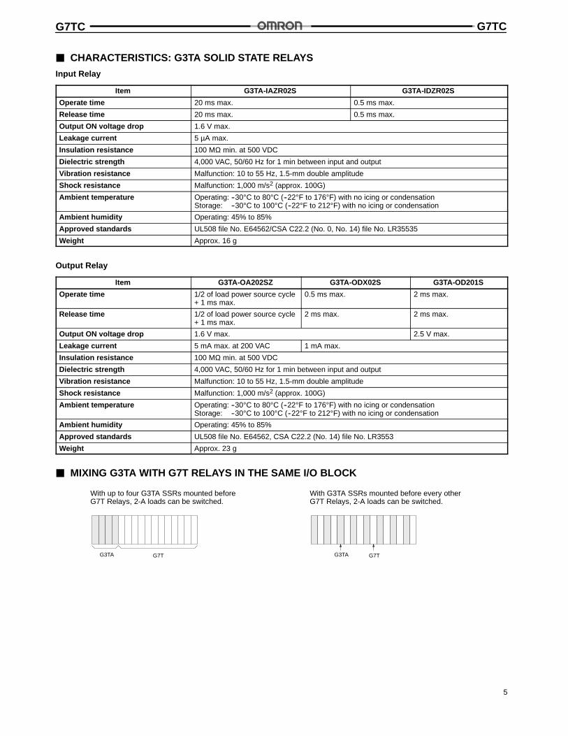
3 CHARACTERISTICS: G3TA SOLID STATE RELAYS
Input Relay
Item G3TA-IAZR02S G3TA-IDZR02S
Operate time 20 ms max. 0.5 ms max.
Release time 20 ms max. 0.5 ms max.
Output ON voltage drop 1.6 V max.
Leakage current 5 µA max.
Insulation resistance 100 MΩ min. at 500 VDC
Dielectric strength 4,000 VAC, 50/60 Hz for 1 min between input and output
Vibration resistance Malfunction: 10 to 55 Hz, 1.5-mm double amplitude
Shock resistance Malfunction: 1,000 m/s2 (approx. 100G)
Ambient temperature Operating: --30°C to 80°C (--22°F to 176°F) with no icing or condensationStorage: --30°C to 100°C (--22°F to 212°F) with no icing or condensation
Ambient humidity Operating: 45% to 85%
Approved standards UL508 file No. E64562/CSA C22.2 (No. 0, No. 14) file No. LR35535
Weight Approx. 16 g
Output Relay
Item G3TA-OA202SZ G3TA-ODX02S G3TA-OD201S
Operate time 1/2 of load power source cycle+ 1 ms max.
0.5 ms max. 2 ms max.
Release time 1/2 of load power source cycle+ 1 ms max.
2 ms max. 2 ms max.
Output ON voltage drop 1.6 V max. 2.5 V max.
Leakage current 5 mA max. at 200 VAC 1 mA max.
Insulation resistance 100 MΩ min. at 500 VDC
Dielectric strength 4,000 VAC, 50/60 Hz for 1 min between input and output
Vibration resistance Malfunction: 10 to 55 Hz, 1.5-mm double amplitude
Shock resistance Malfunction: 1,000 m/s2 (approx. 100G)
Ambient temperature Operating: --30°C to 80°C (--22°F to 176°F) with no icing or condensationStorage: --30°C to 100°C (--22°F to 212°F) with no icing or condensation
Ambient humidity Operating: 45% to 85%
Approved standards UL508 file No. E64562, CSA C22.2 (No. 14) file No. LR3553
Weight Approx. 23 g
3 MIXING G3TA WITH G7T RELAYS IN THE SAME I/O BLOCK
With up to four G3TA SSRs mounted beforeG7T Relays, 2-A loads can be switched.
With G3TA SSRs mounted before every otherG7T Relays, 2-A loads can be switched.
G3TA G7T G3TA G7T
G7TC G7TC
6
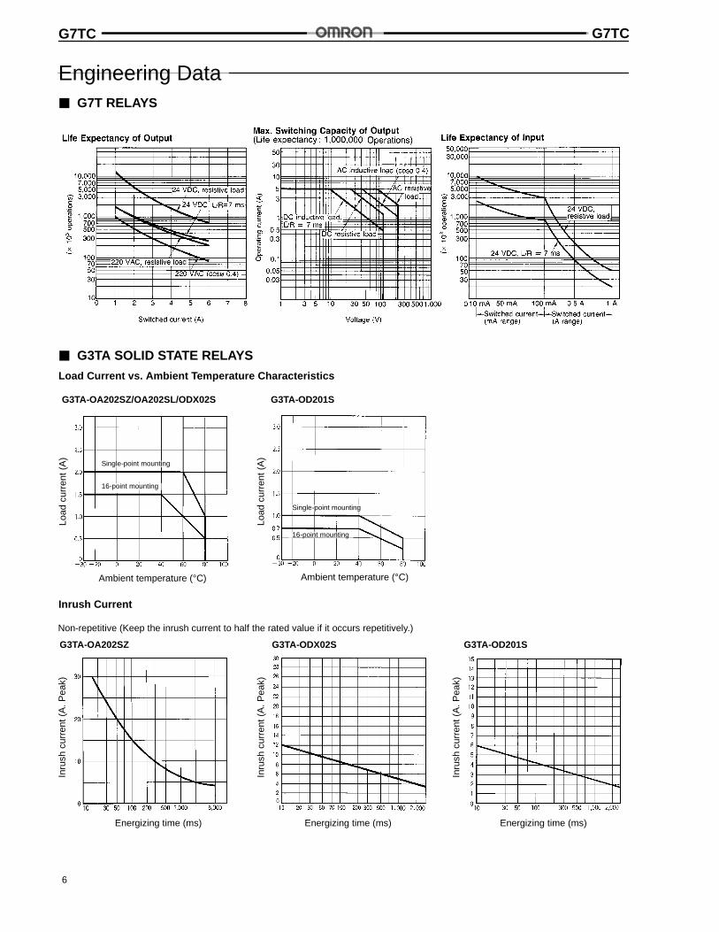
Engineering Data3 G7T RELAYS
3 G3TA SOLID STATE RELAYS
Load Current vs. Ambient Temperature Characteristics
G3TA-OA202SZ/OA202SL/ODX02S
Ambient temperature (°C) Ambient temperature (°C)
Load
curr
ent(
A)
Load
curr
ent(
A)
G3TA-OD201S
Single-point mounting
16-point mounting
Single-point mounting
16-point mounting
Inrush Current
Non-repetitive (Keep the inrush current to half the rated value if it occurs repetitively.)
G3TA-ODX02S G3TA-OD201S
Inru
shcu
rren
t(A
.Pea
k)
Energizing time (ms)
Inru
shcu
rren
t(A
.Pea
k)
Energizing time (ms)
Inru
shcu
rren
t(A
.Pea
k)
Energizing time (ms)
G3TA-OA202SZ
G7TC G7TC
7
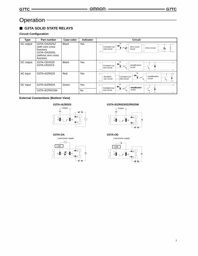
Operation3 G3TA SOLID STATE RELAYS
Circuit Configuration
Type Part number Case color Indicator Circuit
AC output G3TA-OA202SZ(with zero crossfunction)G3TA-OA202SL(without zero crossfunction)
Black YesConstant-cur-rent circuit
Zero crosscircuit Drive circuit
DC output G3TA-ODX02SG3TA-OD201S
Black YesConstant-cur-rent circuit
Amplificationcircuit
AC input G3TA-IAZR02S Red YesAmplificationcircuit
Constant-cur-rent circuit
Rectifica-tion circuit
DC input G3TA-IDZR02S Green YesAmplificationConstant-cur-
G3TA-IDZR02SM NoAmplificationcircuit
Constant-cur-rent circuit
External Connections (Bottom View)
G3TA-IAZR02S G3TA-IDZR02S/IDZR02SM
G3TA-OA G3TA-OD
3+
4-- 5
13+
4-- 5
1
Output Output
3+
45
1
--
Load
Load power supply
3+
4-- 5
1+
--
Load
Load power supply
G7TC G7TC
8
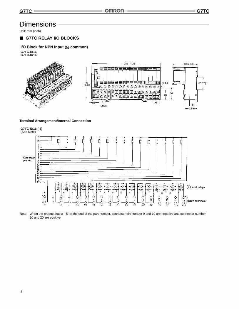
DimensionsUnit: mm (inch)
3 G7TC RELAY I/O BLOCKS
I/O Block for NPN Input ( common)
85(3.35)
182 (7.17) 68 (2.68)
G7TC-ID16G7TC-IA16
Terminal Arrangement/Internal Connection
G7TC-ID16 (-5)(See Note)
Note: When the product has a “-5” at the end of the part number, connector pin number 9 and 19 are negative and connector number10 and 20 are positive.
G7TC G7TC
9
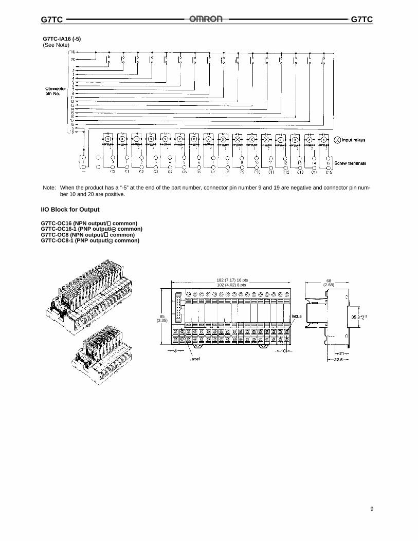
G7TC-IA16 (-5)(See Note)
Note: When the product has a “-5” at the end of the part number, connector pin number 9 and 19 are negative and connector pin num-ber 10 and 20 are positive.
I/O Block for Output
G7TC-OC16 (NPN output/ ⊕⊕⊕⊕ common)G7TC-OC16-1 (PNP output/ common)G7TC-OC8 (NPN output/ ⊕⊕⊕⊕ common)G7TC-OC8-1 (PNP output/ common)
85(3.35)
182 (7.17) 16 pts102 (4.02) 8 pts
68(2.68)
G7TC G7TC
10
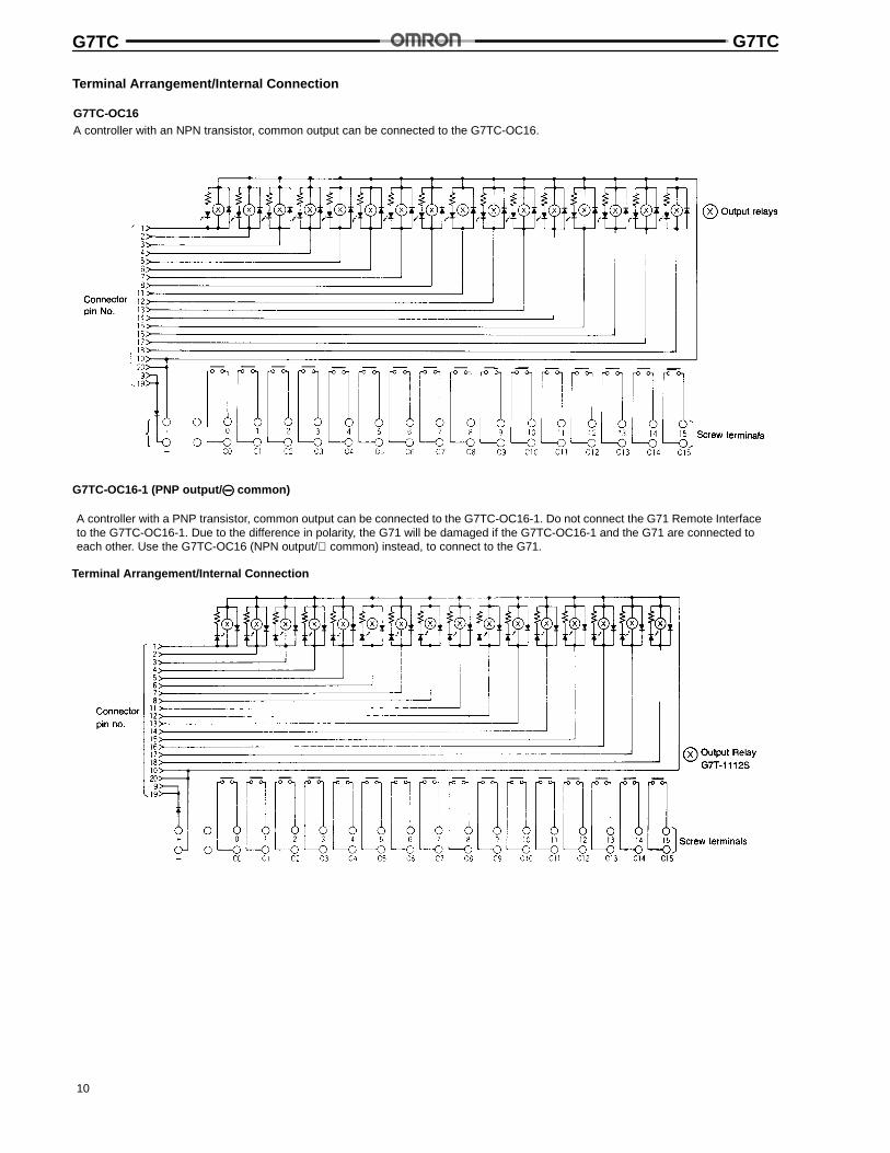
Terminal Arrangement/Internal Connection
G7TC-OC16A controller with an NPN transistor, common output can be connected to the G7TC-OC16.
G7TC-OC16-1 (PNP output/ common)
A controller with a PNP transistor, common output can be connected to the G7TC-OC16-1. Do not connect the G71 Remote Interfaceto the G7TC-OC16-1. Due to the difference in polarity, the G71 will be damaged if the G7TC-OC16-1 and the G71 are connected toeach other. Use the G7TC-OC16 (NPN output/⊕ common) instead, to connect to the G71.
Terminal Arrangement/Internal Connection
G7TC G7TC
11
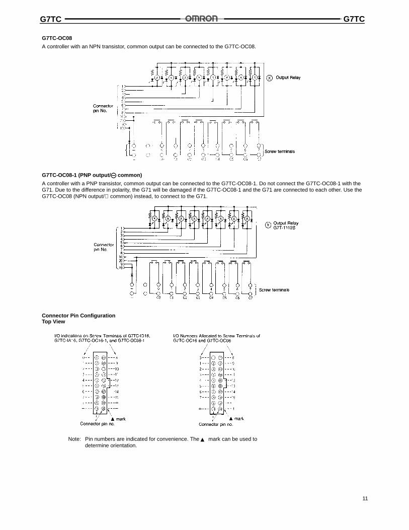
G7TC-OC08
A controller with an NPN transistor, common output can be connected to the G7TC-OC08.
G7TC-OC08-1 (PNP output/ common)
A controller with a PNP transistor, common output can be connected to the G7TC-OC08-1. Do not connect the G7TC-OC08-1 with theG71. Due to the difference in polarity, the G71 will be damaged if the G7TC-OC08-1 and the G71 are connected to each other. Use theG7TC-OC08 (NPN output/⊕ common) instead, to connect to the G71.
Connector Pin ConfigurationTop View
Note: Pin numbers are indicated for convenience. The? mark can be used todetermine orientation.
G7TC G7TC
12
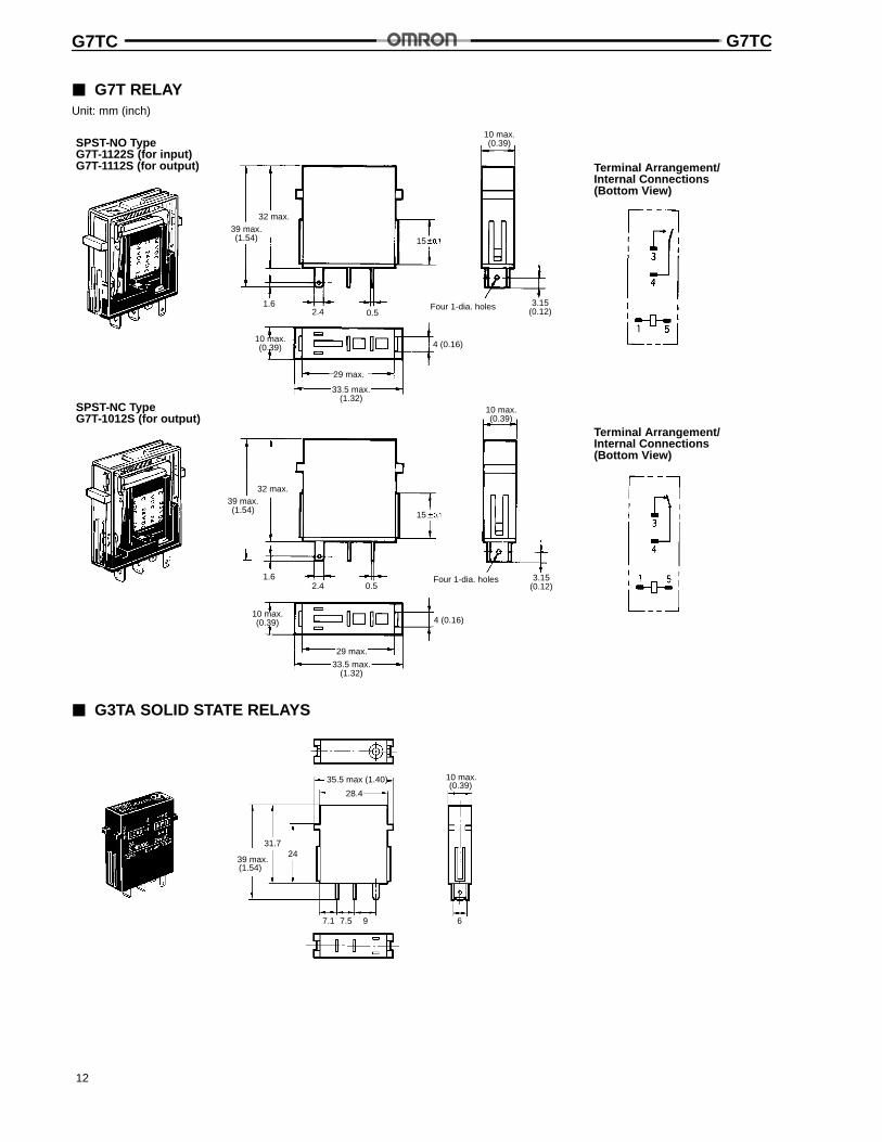
3 G7T RELAYUnit: mm (inch)
SPST-NO TypeG7T-1122S (for input)G7T-1112S (for output)
32 max.39 max.(1.54)
29 max.
10 max.(0.39)
Four 1-dia. holes
Terminal Arrangement/Internal Connections(Bottom View)
SPST-NC TypeG7T-1012S (for output)
32 max.
29 max.
Four 1-dia. holes
Terminal Arrangement/Internal Connections(Bottom View)
3.15(0.12)0.52.4
1.6
15
4 (0.16)10 max.(0.39)
33.5 max.(1.32)
3.15(0.12)
10 max.(0.39)
33.5 max.(1.32)
0.52.41.6
39 max.(1.54) 15
4 (0.16)10 max.(0.39)
3 G3TA SOLID STATE RELAYS
28.4
31.724
7.1 7.5 9 6
35.5 max (1.40)
39 max.(1.54)
10 max.(0.39)
G7TC G7TC
13
Unit: mm (inch)
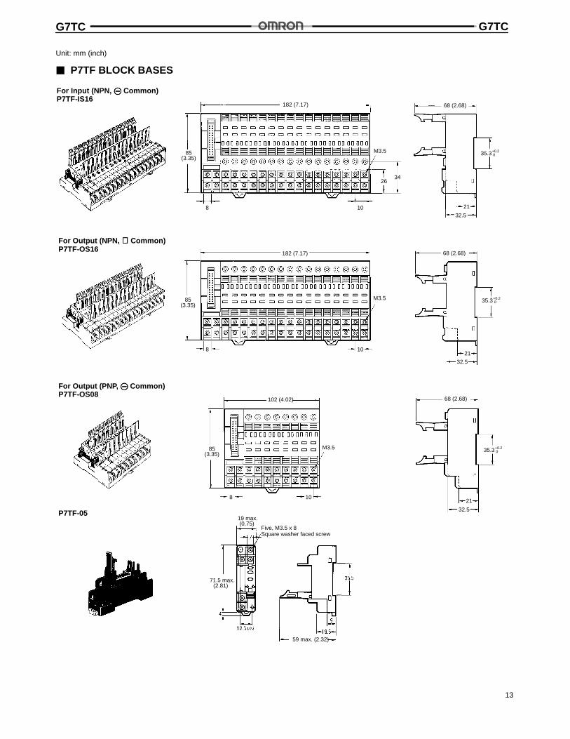
3 P7TF BLOCK BASES
For Input (NPN, Common)P7TF-IS16
32.5
21
2634
8 10
M3.5 35.3+0.20
182 (7.17)
85(3.35)
68 (2.68)
For Output (NPN, ⊕⊕⊕⊕ Common)P7TF-OS16
8 10
M3.5
32.5
21
35.3+0.20
182 (7.17)
85(3.35)
68 (2.68)
For Output (PNP, Common)P7TF-OS08
32.5
21
M3.5
8 10
35.3+0.20
P7TF-05
Five, M3.5 x 8Square washer faced screw
68 (2.68)
85(3.35)
102 (4.02)
71.5 max.(2.81)
59 max. (2.32)
19 max.(0.75)
G7TC G7TC
14
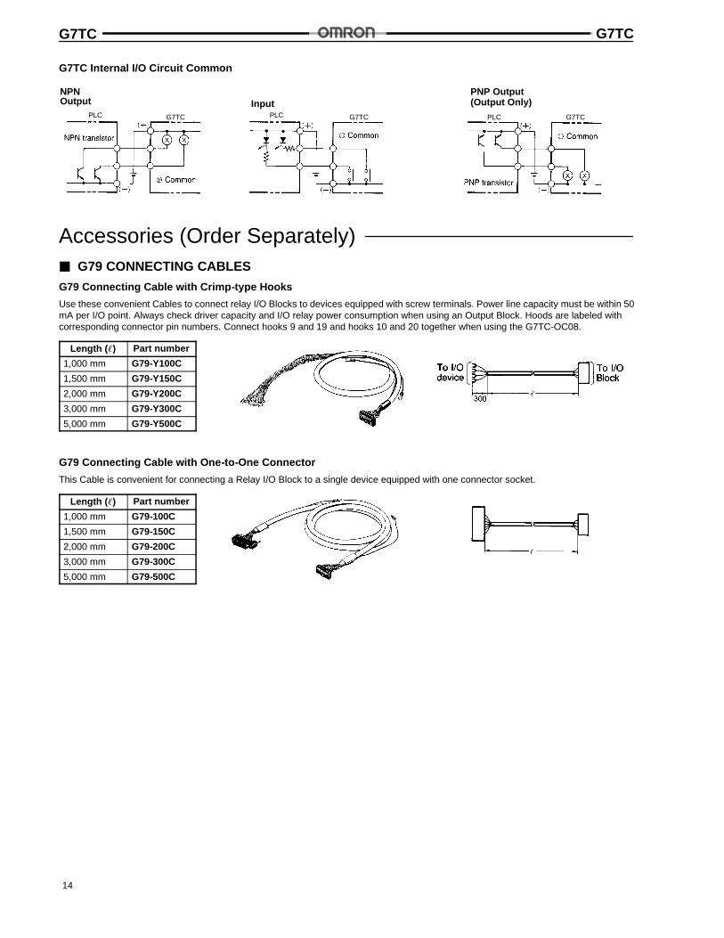
G7TC Internal I/O Circuit Common
PNP Output(Output Only)Input
PLC PLC
NPNOutput
PLCG7TC G7TC G7TC
Accessories (Order Separately)3 G79 CONNECTING CABLES
G79 Connecting Cable with Crimp-type Hooks
Use these convenient Cables to connect relay I/O Blocks to devices equipped with screw terminals. Power line capacity must be within 50mA per I/O point. Always check driver capacity and I/O relay power consumption when using an Output Block. Hoods are labeled withcorresponding connector pin numbers. Connect hooks 9 and 19 and hooks 10 and 20 together when using the G7TC-OC08.
Length ( ç) Part number
1,000 mm G79-Y100C
1,500 mm G79-Y150C
2,000 mm G79-Y200C
3,000 mm G79-Y300C
5,000 mm G79-Y500C
G79 Connecting Cable with One-to-One Connector
This Cable is convenient for connecting a Relay I/O Block to a single device equipped with one connector socket.
Length ( ç) Part number
1,000 mm G79-100C
1,500 mm G79-150C
2,000 mm G79-200C
3,000 mm G79-300C
5,000 mm G79-500C
G7TC G7TC
15
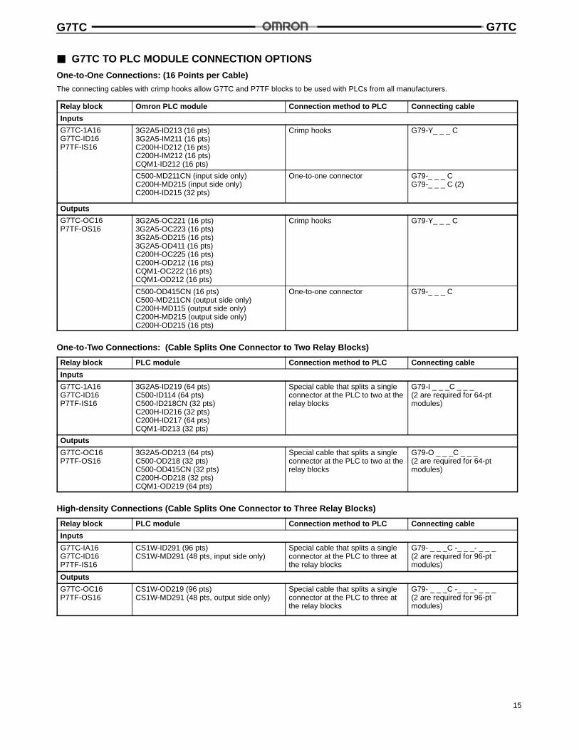
3 G7TC TO PLC MODULE CONNECTION OPTIONS
One-to-One Connections: (16 Points per Cable)
The connecting cables with crimp hooks allow G7TC and P7TF blocks to be used with PLCs from all manufacturers.
Relay block Omron PLC module Connection method to PLC Connecting cable
Inputs
G7TC-1A16G7TC-ID16P7TF-IS16
3G2A5-ID213 (16 pts)3G2A5-IM211 (16 pts)C200H-ID212 (16 pts)C200H-IM212 (16 pts)CQM1-ID212 (16 pts)
Crimp hooks G79-Y_ _ _ C
C500-MD211CN (input side only)C200H-MD215 (input side only)C200H-ID215 (32 pts)
One-to-one connector G79-_ _ _ CG79-_ _ _ C (2)
Outputs
G7TC-OC16P7TF-OS16
3G2A5-OC221 (16 pts)3G2A5-OC223 (16 pts)3G2A5-OD215 (16 pts)3G2A5-OD411 (16 pts)C200H-OC225 (16 pts)C200H-OD212 (16 pts)CQM1-OC222 (16 pts)CQM1-OD212 (16 pts)
Crimp hooks G79-Y_ _ _ C
C500-OD415CN (16 pts)C500-MD211CN (output side only)C200H-MD115 (output side only)C200H-MD215 (output side only)C200H-OD215 (16 pts)
One-to-one connector G79-_ _ _ C
One-to-Two Connections: (Cable Splits One Connector to Two Relay Blocks)
Relay block PLC module Connection method to PLC Connecting cable
Inputs
G7TC-1A16G7TC-ID16P7TF-IS16
3G2A5-ID219 (64 pts)C500-ID114 (64 pts)C500-ID218CN (32 pts)C200H-ID216 (32 pts)C200H-ID217 (64 pts)CQM1-ID213 (32 pts)
Special cable that splits a singleconnector at the PLC to two at therelay blocks
G79-I _ _ _C _ _ _(2 are required for 64-ptmodules)
Outputs
G7TC-OC16P7TF-OS16
3G2A5-OD213 (64 pts)C500-OD218 (32 pts)C500-OD415CN (32 pts)C200H-OD218 (32 pts)CQM1-OD219 (64 pts)
Special cable that splits a singleconnector at the PLC to two at therelay blocks
G79-O _ _ _C _ _ _(2 are required for 64-ptmodules)
High-density Connections (Cable Splits One Connector to Three Relay Blocks)
Relay block PLC module Connection method to PLC Connecting cable
Inputs
G7TC-IA16G7TC-ID16P7TF-IS16
CS1W-ID291 (96 pts)CS1W-MD291 (48 pts, input side only)
Special cable that splits a singleconnector at the PLC to three atthe relay blocks
G79- _ _ _C -_ _ _- _ _ _(2 are required for 96-ptmodules)
Outputs
G7TC-OC16P7TF-OS16
CS1W-OD219 (96 pts)CS1W-MD291 (48 pts, output side only)
Special cable that splits a singleconnector at the PLC to three atthe relay blocks
G79- _ _ _C -_ _ _- _ _ _(2 are required for 96-ptmodules)
G7TC G7TC
16
Unit: mm (inch)
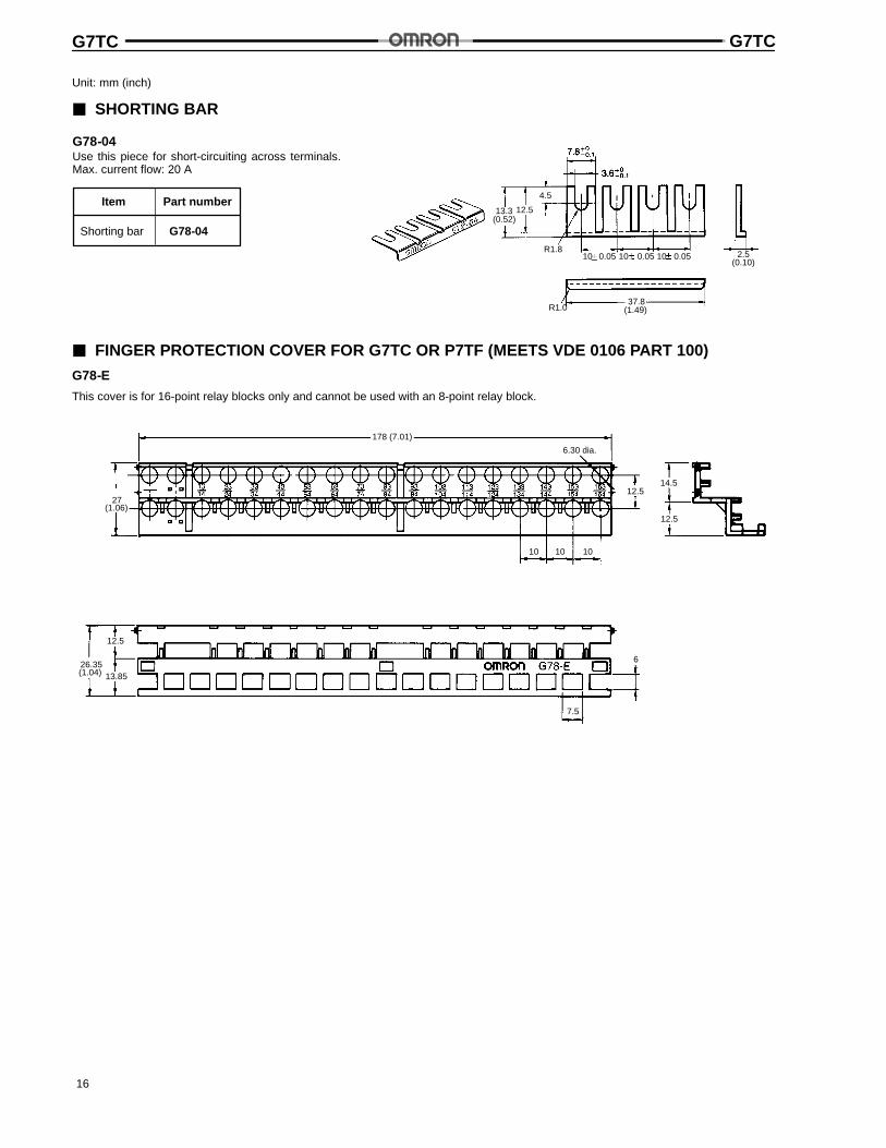
3 SHORTING BAR
Use this piece for short-circuiting across terminals.Max. current flow: 20 A
13.3(0.52)
12.5
4.5
37.8(1.49)
R1.810 0.05 0.05 0.051010 2.5
R1.0
(0.10)
G78-04
Item Part number
Shorting bar G78-04
3 FINGER PROTECTION COVER FOR G7TC OR P7TF (MEETS VDE 0106 PART 100)
G78-E
This cover is for 16-point relay blocks only and cannot be used with an 8-point relay block.
178 (7.01)
27(1.06)
10 10 10
12.5
14.512.5
6.30 dia.
12.5
26.35(1.04) 13.85
7.5
6
G7TC G7TC
17
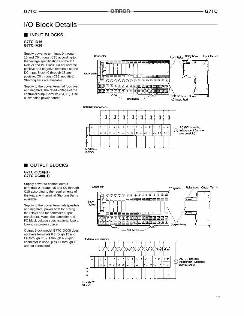
I/O Block Details3 INPUT BLOCKS
G7TC-ID16G7TC-IA16
Supply power to terminals 0 through15 and C0 through C15 according tothe voltage specifications of the I/ORelays and I/O Block. Do not reversepositive and negative terminals on theDC Input Block (0 through 15 arepositive; C0 through C15, negative).Shorting bars are available.
Supply to the power terminal (positiveand negative) the rated voltage of thecontroller’s input circuits (24, 12). Usea low-noise power source.
3 OUTPUT BLOCKS
G7TC-OC16(-1)G7TC-OC08(-1)
Supply power to contact outputterminals 0 through 15 and C0 throughC15 according to the requirements ofthe loads. A 4 terminal Shorting Bar isavailable.
Supply to the power terminals (positiveand negative) power both for drivingthe relays and for controller outputtransistors. Match the controller andI/O block voltage specifications. Use alow-noise power source.
Output Block model G7TC-OC08 doesnot have terminals 8 through 15 andC8 through C15. Although a 20-pinconnector is used, pins 11 through 18are not connected.
G7TC G7TC
18
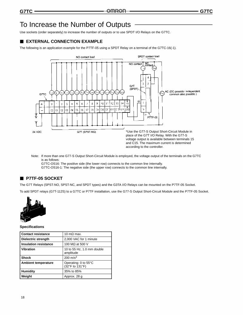
To Increase the Number of OutputsUse sockets (order separately) to increase the number of outputs or to use SPDT I/O Relays on the G7TC.
3 EXTERNAL CONNECTION EXAMPLEThe following is an application example for the P7TF-05 using a SPDT Relay on a terminal of the G7TC-16(-1).
*Use the G77-S Output Short-Circuit Module inplace of the G7T I/O Relay. With the G77-Svoltage output is available between terminals 15and C15. The maximum current is determinedaccording to the controller.
Note: If more than one G77-S Output Short-Circuit Module is employed, the voltage output of the terminals on the G7TCis as follows:G7TC-OS16: The positive side (the lower row) connects to the common line internally.G7TC-OS16-1: The negative side (the upper row) connects to the common line internally.
3 P7TF-05 SOCKETThe G7T Relays (SPST-NO, SPST-NC, and SPDT types) and the G3TA I/O Relays can be mounted on the P7TF-05 Socket.
To add SPDT relays (G7T-112S) to a G7TC or P7TF installation, use the G77-S Output Short-Circuit Module and the P7TF-05 Socket.
Specifications
Contact resistance 10 mΩ max.
Dielectric strength 2,000 VAC for 1 minute
Insulation resistance 100 MΩ at 500 V
Vibration 10 to 55 Hz, 1.0 mm doubleamplitude
Shock 200 m/s2
Ambient temperature Operating: 0 to 55°C(32°F to 131°F)
Humidity 35% to 85%
Weight Approx. 28 g
G7TC G7TC
19
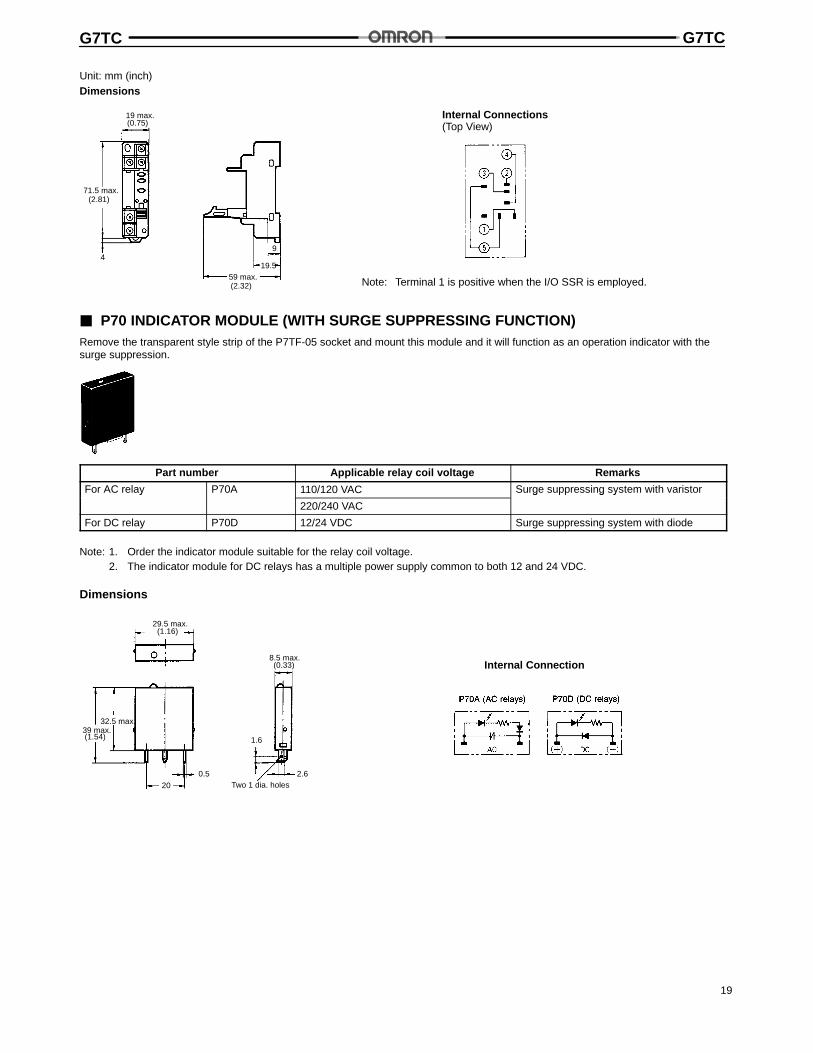
Unit: mm (inch)Dimensions
Note: Terminal 1 is positive when the I/O SSR is employed.
Internal Connections(Top View)
19 max.
71.5 max.(2.81)
59 max.(2.32)
9
19.54
(0.75)
3 P70 INDICATOR MODULE (WITH SURGE SUPPRESSING FUNCTION)Remove the transparent style strip of the P7TF-05 socket and mount this module and it will function as an operation indicator with thesurge suppression.
Part number Applicable relay coil voltage Remarks
For AC relay P70A 110/120 VAC Surge suppressing system with varistory
220/240 VAC
g g y
For DC relay P70D 12/24 VDC Surge suppressing system with diode
Note: 1. Order the indicator module suitable for the relay coil voltage.2. The indicator module for DC relays has a multiple power supply common to both 12 and 24 VDC.
Dimensions
Internal Connection
29.5 max.(1.16)
32.5 max.39 max.
20
0.5
1.6
2.6
8.5 max.
Two 1 dia. holes
(1.54)
(0.33)
G7TC G7TC
20
Unit: mm (inch)
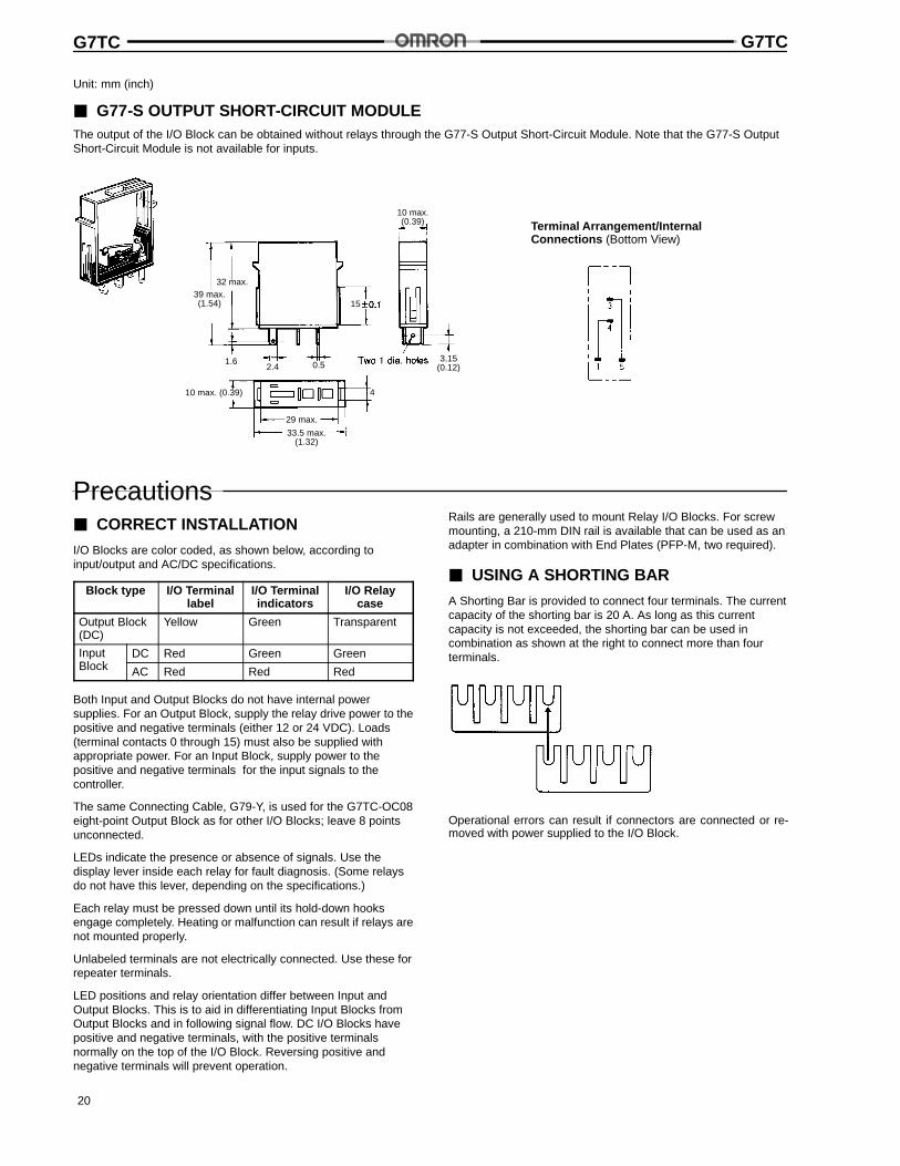
3 G77-S OUTPUT SHORT-CIRCUIT MODULEThe output of the I/O Block can be obtained without relays through the G77-S Output Short-Circuit Module. Note that the G77-S OutputShort-Circuit Module is not available for inputs.
Terminal Arrangement/InternalConnections (Bottom View)
32 max.
3.15(0.12)0.52.4
1.6
39 max.(1.54) 15
29 max.
33.5 max.(1.32)
4
10 max.(0.39)
10 max. (0.39)
Precautions3 CORRECT INSTALLATION
I/O Blocks are color coded, as shown below, according toinput/output and AC/DC specifications.
Block type I/O Terminallabel
I/O Terminalindicators
I/O Relaycase
Output Block(DC)
Yellow Green Transparent
InputBl k
DC Red Green GreenBlock AC Red Red Red
Both Input and Output Blocks do not have internal powersupplies. For an Output Block, supply the relay drive power to thepositive and negative terminals (either 12 or 24 VDC). Loads(terminal contacts 0 through 15) must also be supplied withappropriate power. For an Input Block, supply power to thepositive and negative terminals for the input signals to thecontroller.
The same Connecting Cable, G79-Y, is used for the G7TC-OC08eight-point Output Block as for other I/O Blocks; leave 8 pointsunconnected.
LEDs indicate the presence or absence of signals. Use thedisplay lever inside each relay for fault diagnosis. (Some relaysdo not have this lever, depending on the specifications.)
Each relay must be pressed down until its hold-down hooksengage completely. Heating or malfunction can result if relays arenot mounted properly.
Unlabeled terminals are not electrically connected. Use these forrepeater terminals.
LED positions and relay orientation differ between Input andOutput Blocks. This is to aid in differentiating Input Blocks fromOutput Blocks and in following signal flow. DC I/O Blocks havepositive and negative terminals, with the positive terminalsnormally on the top of the I/O Block. Reversing positive andnegative terminals will prevent operation.
Rails are generally used to mount Relay I/O Blocks. For screwmounting, a 210-mm DIN rail is available that can be used as anadapter in combination with End Plates (PFP-M, two required).
3 USING A SHORTING BAR
A Shorting Bar is provided to connect four terminals. The currentcapacity of the shorting bar is 20 A. As long as this currentcapacity is not exceeded, the shorting bar can be used incombination as shown at the right to connect more than fourterminals.
Operational errors can result if connectors are connected or re-moved with power supplied to the I/O Block.
G7TC G7TC
Cat. No. GC RIO-1 04/00 Specifications subject to change without notice. Printed in U.S.A.
OMRON ELECTRONICS, INC.One East Commerce DriveSchaumburg, IL 60173
NOTE: DIMENSIONS SHOWN ARE IN MILLIMETERS. To convert millimeters to inches divide by 25.4.
1-800-55-OMRON
OMRON CANADA, INC.885 Milner AvenueScarborough, Ontario M1B 5V8
416-286-6465
9