Embed Size (px)
Citation preview
48
Relay Technical Information
Definition of Relay Terminology
COIL
(also referred to as primary or input)
• Nominal Coil Voltage
(Rated Coil Volt-age)A single value (or narrow range) of source voltage intended by design to be applied to the coil or input.
• Pick-Up Voltage
(Pull-In Voltage or Must Operate Voltage)As the voltage on an unoperated relay is increased, the value at or below which all contacts must function (transfer).
• Drop-Out Voltage
(Release or Must Re-lease Voltage)As the voltage on an operated relay is de-
creased, the value at or above which all contacts must revert to their unoperated position.
• Maximum Continuous Voltage
The maximum voltage that can be applied continuously to the coil without causing damage. Short duration spikes of a higher voltage may be tolerable, but this should not be assumed without first checking with the manufacturer.
• Nominal Operating Current
The value of current flow in the coil when nominal voltage is impressed on the coil
• Nominal Operating Power
The value of power used by the coil at nominal voltage. For DC coils expressed in watts; AC expressed as volt amperes. Nominal Power (W or VA) = Nominal Volt-age
×
Nominal Current.
• Coil Resistance
This is the DC resistance of the coil in DC type relays for the temperature conditions listed in the catalog. (Note that for certain types of relays, the DC resistance may be for temperatures other than the standard 20
°
C 68
°
F.)
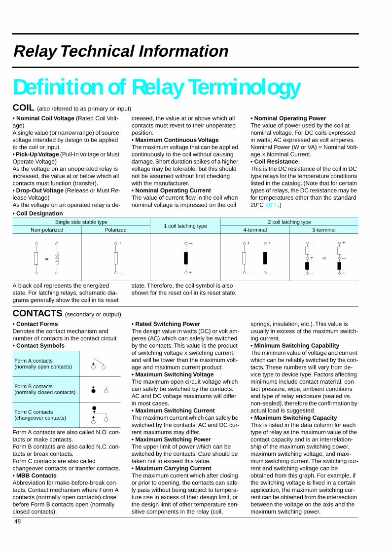
• Coil Designation
A black coil represents the energized state. For latching relays, schematic dia-grams generally show the coil in its reset
state. Therefore, the coil symbol is also shown for the reset coil in its reset state.
Single side stable type1 coil latching type
2 coil latching type
Non-polarized Polarized 4-terminal 3-terminal
or
+
— +
— +
—
+
—
or+
—
—
—
+
+
CONTACTS
(secondary or output)
• Contact Forms
Denotes the contact mechanism and number of contacts in the contact circuit.
• Contact Symbols
Form A contacts are also called N.O. con-tacts or make contacts.Form B contacts are also called N.C. con-tacts or break contacts.Form C contacts are also called changeover contacts or transfer contacts.
• MBB Contacts
Abbreviation for make-before-break con-tacts. Contact mechanism where Form A contacts (normally open contacts) close before Form B contacts open (normally closed contacts).
• Rated Switching Power
The design value in watts (DC) or volt am-peres (AC) which can safely be switched by the contacts. This value is the product of switching voltage x switching current, and will be lower than the maximum volt-age and maximum current product.
• Maximum Switching Voltage
The maximum open circuit voltage which can safely be switched by the contacts. AC and DC voltage maximums will differ in most cases.
• Maximum Switching Current
The maximum current which can safely be switched by the contacts. AC and DC cur-rent maximums may differ.
• Maximum Switching Power
The upper limit of power which can be switched by the contacts. Care should be taken not to exceed this value.
• Maximum Carrying Current
The maximum current which after closing or prior to opening, the contacts can safe-ly pass without being subject to tempera-ture rise in excess of their design limit, or the design limit of other temperature sen-sitive components in the relay (coil,
springs, insulation, etc.). This value is usually in excess of the maximum switch-ing current.
• Minimum Switching Capability
The minimum value of voltage and current which can be reliably switched by the con-tacts. These numbers will vary from de-vice type to device type. Factors affecting minimums include contact material, con-tact pressure, wipe, ambient conditions and type of relay enclosure (sealed vs. non-sealed), therefore the confirmation by actual load is suggested.
• Maximum Switching Capacity
This is listed in the data column for each type of relay as the maximum value of the contact capacity and is an interrelation-ship of the maximum switching power, maximum switching voltage, and maxi-mum switching current. The switching cur-rent and switching voltage can be obtained from this graph. For example, if the switching voltage is fixed in a certain application, the maximum switching cur-rent can be obtained from the intersection between the voltage on the axis and the maximum switching power.
Form A contacts (normally open contacts)
Form B contacts (normally closed contacts)
Form C contacts (changeover contacts)
49
Definition of Relay Terminology
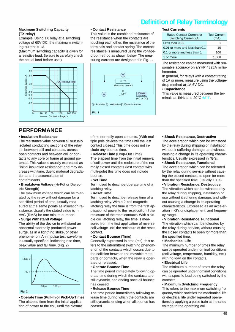
Maximum Switching Capacity (TX relay)
Example: Using TX relay at a switching voltage of 60V DC, the maximum switch-ing current is 1A.(Maximum switching capacity is given for a resistive load. Be sure to carefully check the actual load before use.)
• Contact Resistance
This value is the combined resistance of the resistance when the contacts are touching each other, the resistance of the terminals and contact spring. The contact resistance is measured using the voltage-drop method as shown below. The mea-suring currents are designated in Fig. 1.
Test Currents
The resistance can be measured with rea-sonable accuracy on a YHP 4328A millio-hmmeter.In general, for relays with a contact rating of 1A or more, measure using the voltage-drop method at 1A 6V DC.
• Capacitance
This value is measured between the ter-minals at 1kHz and 20
°
C 68
°
F.0.2
0.3
0.40.5
1.0
2.0
3.0
20 30 50 100 200 300
DC resistive load
0Contact voltage, V
Sw
itchi
ng c
urre
nt, A
Fig. 1
A
V
R
AmmeterA : V : Voltmeter R : Variable resister
(AC or DC)
Powersource
Measured contact
Rated Contact Current or Switching Current (A)
Test Current (mA)
Less than 0.01 1
0.01 or more and less than 0.1 10
0.1 or more and less than 1 100
1 or more 1,000
PERFORMANCE
• Insulation Resistance
The resistance value between all mutually isolated conducting sections of the relay, i.e. between coil and contacts, across open contacts and between coil or con-tacts to any core or frame at ground po-tential. This value is usually expressed as "initial insulation resistance" and may de-crease with time, due to material degrada-tion and the accumulation of contaminants.
• Breakdown Voltage
(Hi-Pot or Dielec-tric Strength)The maximum voltage which can be toler-ated by the relay without damage for a specified period of time, usually mea-sured at the same points as insulation re-sistance. Usually the stated value is in VAC (RMS) for one minute duration.
• Surge Withstand Voltage
The ability of the device to withstand an abnormal externally produced power surge, as in a lightning strike, or other phenomenon. An impulse test waveform is usually specified, indicating rise time, peak value and fall time. (Fig. 2)
• Operate Time (Pull-In or Pick-Up Time)
The elapsed time from the initial applica-tion of power to the coil, until the closure
of the normally open contacts. (With mul-tiple pole devices the time until the last contact closes.) This time does not in-clude any bounce time.
• Release Time
(Drop-Out Time)The elapsed time from the initial removal of coil power until the reclosure of the nor-mally closed contacts (last contact with multi-pole) this time does not include bounce.
• Set Time
Term used to describe operate time of a latching relay.
• Reset Time
Term used to describe release time of a latching relay. With a 2-coil magnetic latching relay the time is from the first ap-plication of power to the reset coil until the reclosure of the reset contacts. With a sin-gle coil latching relay, the time is mea-sured from the first application of reverse coil voltage until the reclosure of the reset contact.
• Contact Bounce
(Time)Generally expressed in time (ms), this re-fers to the intermittent switching phenom-enon of the contacts which occurs due to the collision between the movable metal parts or contacts, when the relay is oper-ated or released.
• Operate Bounce Time
The time period immediately following op-erate time during which the contacts are still dynamic, and ending once all bounce has ceased.
• Release Bounce Time
The time period immediately following re-lease time during which the contacts are still dynamic, ending when all bounce has ceased.
• Shock Resistance, Destructive
The acceleration which can be withstood by the relay during shipping or installation without it suffering damage, and without causing a change in its operating charac-teristics. Usually expressed in "G"s.
• Shock Resistance, Functional
The acceleration which can be tolerated by the relay during service without caus-ing the closed contacts to open for more than the specified time. (usually 10
µ
s)
• Vibration Resistance, Destructive
The vibration which can be withstood by the relay during shipping, installation or use without it suffering damage, and with-out causing a change in its operating characteristics. Expressed as an acceler-ation in G's or displacement, and frequen-cy range.
• Vibration Resistance, Functional
The vibration which can be tolerated by the relay during service, without causing the closed contacts to open for more than the specified time.
• Mechanical Life
The minimum number of times the relay can be operated under nominal conditions (coil voltage, temperature, humidity, etc.) with no load on the contacts.
• Electrical Life
The minimum number of times the relay can be operated under nominal conditions with a specific load being switched by the contacts.
• Maximum Switching Frequency
This refers to the maximum switching fre-quency which satisfies the mechanical life or electrical life under repeated opera-tions by applying a pulse train at the rated voltage to the operating coil.
Fig. 2
10 µs
750 V
1,500 V
160 µs
50
Definition of Relay Terminology
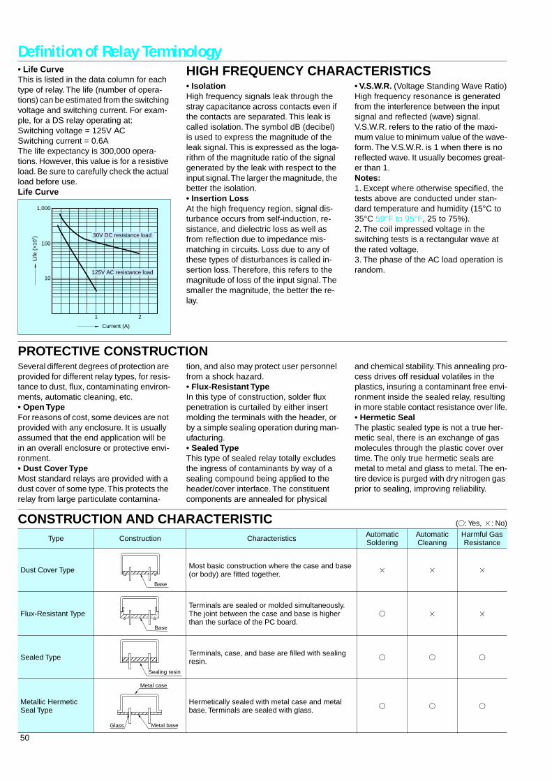
• Life Curve
This is listed in the data column for each type of relay. The life (number of opera-tions) can be estimated from the switching voltage and switching current. For exam-ple, for a DS relay operating at:Switching voltage = 125V ACSwitching current = 0.6AThe life expectancy is 300,000 opera-tions. However, this value is for a resistive load. Be sure to carefully check the actual load before use.
Life Curve
100
10
1 2
1,000
Current (A)
Life
(×1
04 ) 30V DC resistance load
125V AC resistance load
HIGH FREQUENCY CHARACTERISTICS
• Isolation
High frequency signals leak through the stray capacitance across contacts even if the contacts are separated. This leak is called isolation. The symbol dB (decibel) is used to express the magnitude of the leak signal. This is expressed as the loga-rithm of the magnitude ratio of the signal generated by the leak with respect to the input signal. The larger the magnitude, the better the isolation.
• Insertion Loss
At the high frequency region, signal dis-turbance occurs from self-induction, re-sistance, and dielectric loss as well as from reflection due to impedance mis-matching in circuits. Loss due to any of these types of disturbances is called in-sertion loss. Therefore, this refers to the magnitude of loss of the input signal. The smaller the magnitude, the better the re-lay.
• V.S.W.R.
(Voltage Standing Wave Ratio)High frequency resonance is generated from the interference between the input signal and reflected (wave) signal.V.S.W.R. refers to the ratio of the maxi-mum value to minimum value of the wave-form. The V.S.W.R. is 1 when there is no reflected wave. It usually becomes great-er than 1.
Notes:
1. Except where otherwise specified, the tests above are conducted under stan-dard temperature and humidity (15
°
C to 35
°
C 59
°
F to 95
°
F, 25 to 75%).2. The coil impressed voltage in the switching tests is a rectangular wave at the rated voltage.3. The phase of the AC load operation is random.
PROTECTIVE CONSTRUCTION
Several different degrees of protection are provided for different relay types, for resis-tance to dust, flux, contaminating environ-ments, automatic cleaning, etc.
• Open Type
For reasons of cost, some devices are not provided with any enclosure. It is usually assumed that the end application will be in an overall enclosure or protective envi-ronment.
• Dust Cover Type
Most standard relays are provided with a dust cover of some type. This protects the relay from large particulate contamina-
tion, and also may protect user personnel from a shock hazard.
• Flux-Resistant Type
In this type of construction, solder flux penetration is curtailed by either insert molding the terminals with the header, or by a simple sealing operation during man-ufacturing.
• Sealed Type
This type of sealed relay totally excludes the ingress of contaminants by way of a sealing compound being applied to the header/cover interface. The constituent components are annealed for physical
and chemical stability. This annealing pro-cess drives off residual volatiles in the plastics, insuring a contaminant free envi-ronment inside the sealed relay, resulting in more stable contact resistance over life.
• Hermetic Seal
The plastic sealed type is not a true her-metic seal, there is an exchange of gas molecules through the plastic cover over time. The only true hermetic seals are metal to metal and glass to metal. The en-tire device is purged with dry nitrogen gas prior to sealing, improving reliability.
CONSTRUCTION AND CHARACTERISTIC
(
V
: Yes,
2
: No)
Type Construction Characteristics Automatic Soldering
Automatic Cleaning
Harmful Gas Resistance
Dust Cover Type Most basic construction where the case and base (or body) are fitted together.
2 2 2
Flux-Resistant TypeTerminals are sealed or molded simultaneously. The joint between the case and base is higher than the surface of the PC board.
V 2 2
Sealed Type Terminals, case, and base are filled with sealing resin.
V V V
Metallic Hermetic Seal Type
Hermetically sealed with metal case and metal base. Terminals are sealed with glass.
V V V
Base
Base Sealing resin
Metal baseGlass
Metal case
51
Definition of Relay Terminology
OPERATIONAL FUNCTION
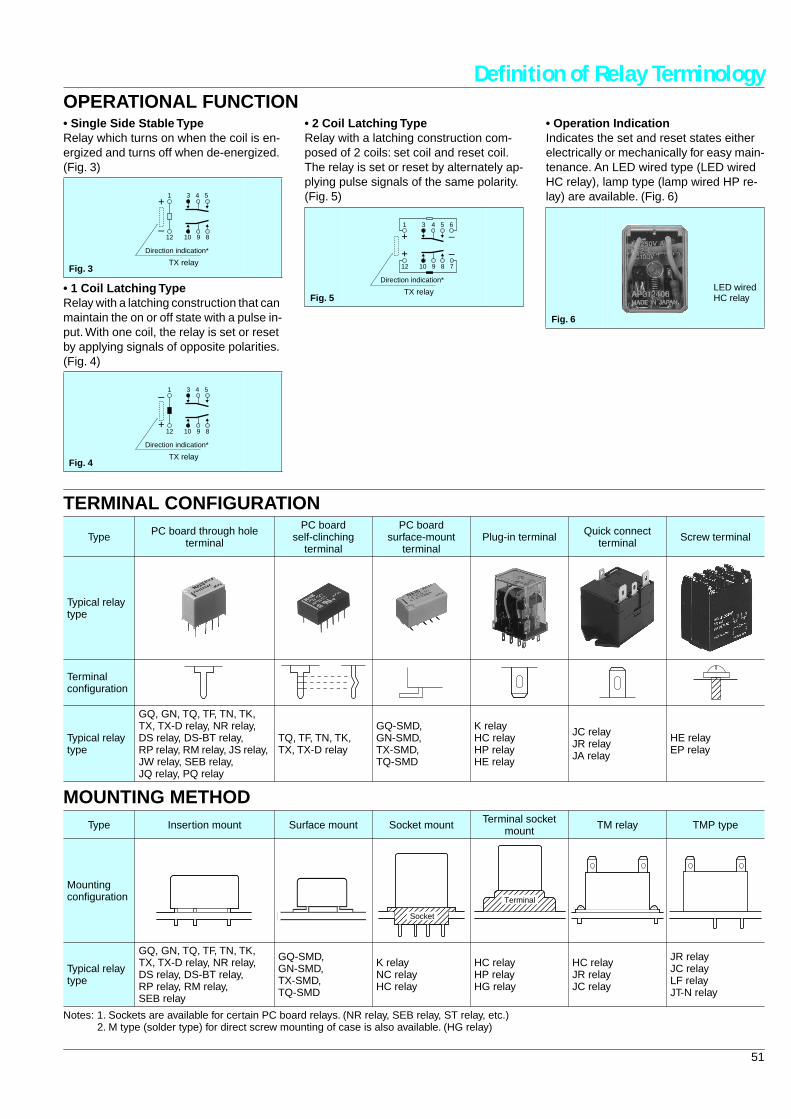
• Single Side Stable Type
Relay which turns on when the coil is en-ergized and turns off when de-energized. (Fig. 3)
• 1 Coil Latching Type
Relay with a latching construction that can maintain the on or off state with a pulse in-put. With one coil, the relay is set or reset by applying signals of opposite polarities. (Fig. 4)
• 2 Coil Latching Type
Relay with a latching construction com-posed of 2 coils: set coil and reset coil. The relay is set or reset by alternately ap-plying pulse signals of the same polarity. (Fig. 5)
• Operation Indication
Indicates the set and reset states either electrically or mechanically for easy main-tenance. An LED wired type (LED wired HC relay), lamp type (lamp wired HP re-lay) are available. (Fig. 6)
Fig. 3
Fig. 4
Direction indication*
TX relay
12 10 9 8
1 3 4 5+
–
Direction indication*
12 10 9 8
1 3 4 5
+
–
TX relay
Fig. 5
Direction indication*
12 10 9 8 7
1 3 4 5 6
+
+
–
–
TX relay
Fig. 6
LED wired HC relay
TERMINAL CONFIGURATION
MOUNTING METHOD
Notes: 1. Sockets are available for certain PC board relays. (NR relay, SEB relay, ST relay, etc.)2. M type (solder type) for direct screw mounting of case is also available. (HG relay)
Type PC board through hole terminal
PC board self-clinching
terminal
PC board surface-mount
terminalPlug-in terminal Quick connect
terminal Screw terminal
Typical relay type
Terminal configuration
Typical relay type
GQ, GN, TQ, TF, TN, TK, TX, TX-D relay, NR relay, DS relay, DS-BT relay, RP relay, RM relay, JS relay, JW relay, SEB relay, JQ relay, PQ relay
TQ, TF, TN, TK, TX, TX-D relay
GQ-SMD, GN-SMD, TX-SMD, TQ-SMD
K relayHC relayHP relayHE relay
JC relayJR relayJA relay
HE relayEP relay
Type Insertion mount Surface mount Socket mount Terminal socket mount TM relay TMP type
Mounting configuration
Typical relay type
GQ, GN, TQ, TF, TN, TK, TX, TX-D relay, NR relay, DS relay, DS-BT relay, RP relay, RM relay, SEB relay
GQ-SMD, GN-SMD, TX-SMD, TQ-SMD
K relayNC relayHC relay
HC relayHP relayHG relay
HC relayJR relayJC relay
JR relayJC relayLF relayJT-N relay
Socket
Terminal
52
General Application Guidelines
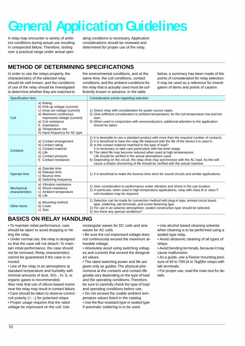
A relay may encounter a variety of ambi-ent conditions during actual use resulting in unexpected failure. Therefore, testing over a practical range under actual oper-
ating conditions is necessary. Application considerations should be reviewed and determined for proper use of the relay.
METHOD OF DETERMINING SPECIFICATIONS
In order to use the relays properly, the characteristics of the selected relay should be well known, and the conditions of use of the relay should be investigated to determine whether they are matched to
the environmental conditions, and at the same time, the coil conditions, contact conditions, and the ambient conditions for the relay that is actually used must be suf-ficiently known in advance. In the table
below, a summary has been made of the points of consideration for relay selection. It may be used as a reference for investi-gation of items and points of caution.
BASICS ON RELAY HANDLING
• To maintain initial performance, care should be taken to avoid dropping or hit-ting the relay.• Under normal use, the relay is designed so that the case will not detach. To main-tain initial performance, the case should not be removed. Relay characteristics cannot be guaranteed if the case is re-moved.• Use of the relay in an atmosphere at standard temperature and humidity with minimal amounts of dust, SO
2
, H
2
S, or organic gases is recommended.Also note that use of silicon-based resins near the relay may result in contact failure.• Care should be taken to observe correct coil polarity (+, –) for polarized relays.• Proper usage requires that the rated voltage be impressed on the coil. Use
rectangular waves for DC coils and sine waves for AC coils.• Be sure the coil impressed voltage does not continuously exceed the maximum al-lowable voltage.• Absolutely avoid using switching voltag-es and currents that exceed the designat-ed values.• The rated switching power and life are given only as guides. The physical phe-nomena at the contacts and contact life greatly vary depending on the type of load and the operating conditions. Therefore, be sure to carefully check the type of load and operating conditions before use.• Do not exceed the usable ambient tem-perature values listed in the catalog.• Use the flux-resistant type or sealed type if automatic soldering is to be used.
• Use alcohol based cleaning solvents when cleaning is to be performed using a sealed type relay.• Avoid ultrasonic cleaning of all types of relays.• Avoid bending terminals, because it may cause malfunction.• As a guide, use a Faston mounting pres-sure of 40 to 70N 4 to 7kgffor relays with tab terminals.• For proper use, read the main text for de-tails.
Specification item Consideration points regarding selection
Coil
a)b)c)d)
e)f)g)h)
RatingPick-up voltage (current)Drop-out voltage (current)Maximum continuous impressed voltage (current)Coil resistanceImpedanceTemperature riseInput frequency for AC type
1)2)
3)
Select relay with consideration for power source ripple.Give sufficient consideration to ambient temperature, for the coil temperature rise and hot start.When used in conjunction with semiconductors, additional attention to the application should be taken.
Contacts
a)b)c)d)e)f)
Contact arrangementContact ratingContact materialLifeContact pressureContact resistance
1)2)3)
4)
5)
It is desirable to use a standard product with more than the required number of contacts.It is beneficial to have the relay life balanced with the life of the device it is used in.Is the contact material matched to the type of load?It is necessary to take care particularly with low level usage.The rated life may become reduced when used at high temperatures.Life should be verified in the actual atmosphere used.Depending on the circuit, the relay drive may synchronize with the AC load. As this will cause a drastic shortening of life should be verified with the actual machine.
Operate time
a)b)c)d)
Operate timeRelease timeBounce timeSwitching frequency
1) It is beneficial to make the bounce time short for sound circuits and similar applications.
Mechanical characteristics
a)b)c)d)
Vibration resistanceShock resistanceAmbient temperatureLife
1)2)
Give consideration to performance under vibration and shock in the use location.In particular, when used in high temperature applications, relay with class B or class F coil insulation may be required.
Other itemsa)b)c)
Mounting methodCoverSize
1)
2)3)
Selection can be made for connection method with plug-in type, printed circuit board type, soldering, tab terminals, and screw fastening type.For use in an adverse atmosphere, sealed construction type should be selected.Are there any special conditions?
53
General Application Guidelines
PROBLEM POINTS WITH REGARD TO USE
In the actual use of relays, various ambi-ent conditions are encountered, and be-cause unforeseen events occur which can not be thought of on the drawing board, with regard to such conditions, tests are
necessary under the possible range of op-eration. For example, consideration must always be given to variation of perfor-mance when relay characteristics are be-ing reviewed. The relay is a mass
production item, and as a matter of princi-ple, it must be recognized that the relay is to be used to the extent of such variations without the need for adjustment.
RELAY COIL
• AC operation type
For the operation of AC relays, the power source is almost always a commercial fre-quency (50 or 60Hz) with standard voltag-es of 6, 12, 24, 48, 115, and 240V AC. Because of this, when the voltage is other than the standard voltage, the product is a special order item, and the factors of price, delivery, and stability of characteris-tics may create inconveniences. To the ex-tent that it is possible, the standard voltages should be selected.Also, in the AC type, shading coil resis-tance loss, magnetic circuit eddy current loss, and hysteresis loss exit, and be-cause of lower coil efficiency, it is normal for the temperature rise to be greater than that for the DC type.Furthermore, because humming occurs below the level of pick-up voltage (mini-mum operating voltage), care is required with regard to power source voltage fluc-tuations.For example, in the case of motor starting, if the power source voltage drops, and during the humming of the relay, if it re-verts to the restored condition, the con-tacts suffer a burn damage and welding, with the occurrence of a false operation self-maintaining condition.For the AC type, there is an inrush current during the operation time (for the separat-ed condition of the armature, the imped-ance is low and a current greater than rated current flows; for the adhered condi-tion of the armature, the impedance is high and the rated value of current flows), and because of this, for the case of sever-al relays being used in parallel connec-tion, it is necessary to give consideration to power consumption.
• DC operation type
For the operation of DC relays, standards exist for power source voltage and cur-rent, with DC voltage standards set at 5, 6, 12, 24, 48, and 100V, but with regard to current, the values as expressed in cata-logs in milliamperes of pick-up current.However, because this value of pick-up current is nothing more than a guarantee of just barely moving the armature, the variation in energizing voltage and resis-tance values, and the increase in coil re-sistance due to temperature rise, must be
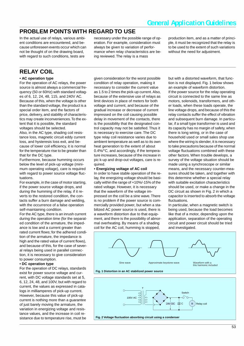
given consideration for the worst possible condition of relay operation, making it necessary to consider the current value as 1.5 to 2 times the pick-up current. Also, because of the extensive use of relays as limit devices in place of meters for both voltage and current, and because of the gradual increase or decrease of current impressed on the coil causing possible delay in movement of the contacts, there is the possibility that the designated con-trol capacity may not be satisfied. Thus it is necessary to exercise care. The DC type relay coil resistance varies due to ambient temperature as well as to its own heat generation to the extent of about 0.4%/°C, and accordingly, if the tempera-ture increases, because of the increase in pic k-up and drop-out voltages, care is re-quired.• Energizing voltage of AC coilIn order to have stable operation of the re-lay, the energizing voltage should be basi-cally within the range of +10%/-15% of the rated voltage. However, it is necessary that the waveform of the voltage im-pressed on the coil be a sine wave. There is no problem if the power source is com-mercially provided power, but when a sta-bilized AC power source is used, there is a waveform distortion due to that equip-ment, and there is the possibility of abnor-mal overheating. By means of a shading coil for the AC coil, humming is stopped,
but with a distorted waveform, that func-tion is not displayed. Fig. 1 below shows an example of waveform distortion.If the power source for the relay operating circuit is connected to the same line as motors, solenoids, transformers, and oth-er loads, when these loads operate, the line voltage drops, and because of this the relay contacts suffer the effect of vibration and subsequent burn damage. In particu-lar, if a small type transformer is used and its capacity has no margin of safety, when there is long wiring, or in the case of household used or small sales shop use where the wiring is slender, it is necessary to take precautions because of the normal voltage fluctuations combined with these other factors. When trouble develops, a survey of the voltage situation should be made using a synchroscope or similar means, and the necessary counter-mea-sures should be taken, and together with this determine whether a special relay with suitable excitation characteristics should be used, or make a change in the DC circuit as shown in Fig. 2 in which a capacitor is inserted to absorb the voltage fluctuations.In particular, when a magnetic switch is being used, because the load becomes like that of a motor, depending upon the application, separation of the operating circuit and power circuit should be tried and investigated.
Fig. 1 Distortion in an AC stabilized power source
Fig. 2 Voltage fluctuation absorbing circuit using a condenser
Sine wave Approximate keystone wave Waveform with athis harmonic included
C
T
R
100V AC
Switch
24V DC Relay coil
54
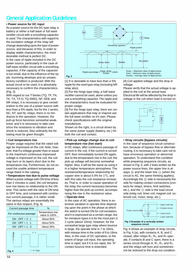
General Application Guidelines• Power source for DC inputAs a power source for the DC type relay, a battery or either a half wave or full wave rectifier circuit with a smoothing capacitor is used. The characteristics with regard to the excitation voltage of the relay will change depending upon the type of power source, and because of this, in order to display stable characteristics, the most desirable method is perfect DC.In the case of ripple included in the DC power source, particularly in the case of half wave rectifier circuit with a smoothing capacitor, if the capacity of the capacitor is too small, due to the influence of the rip-ple, humming develops and an unsatis-factory condition is produced. With the actual circuit to be used, it is absolutely necessary to confirm the characteristics. (Fig. 3)With regard to our T-Series (TQ, TF, TN, TK, TX, TX-D, TQ-SMD), NF, SEB, and NR relays, it is necessary to give consid-eration to the use of a power source with less than a 5% ripple, but for the J series, NC, NT, and NL relays, there is no hin-drance to the operation. However, the pull-up force becomes somewhat weak-ened, and it is necessary to take care since the resistance to vibration and shock is reduced. Also ordinarily the fol-lowing must be given thought.
[1] It is desirable to have less than a 5% ripple for the reed type relay (including NR relay also).[2] For the hinge type relay, a half wave rectifier cannot be used, alone unless you use a smoothing capacitor. The ripple and the characteristics must be evaluated for proper usage.[3] For the hinge type relay, there are cer-tain applications that may or maynot use the full wave rectifier on it's own. Please check specifications with the original manufacture.Shown on the right, is a circuit driven by the same power supply (battery, etc.) for both the coil and contact.
[4] Coil applied voltage and the drop in voltage.Please verify that the actual voltage is ap-plied to the coil at the actual load.Electrical life will be affected by the drop in voltage in the coil when load is turned on.
Load
Fig. 3
R
×100%Emax.–Emin Emax. = Maximum value of ripple portionEmin. = Minimum value of ripple portionEmean.
Emax. Emin. Emean.
Smoothing capacitor
Relay
DC portion
Ripple portion
Ripple percentage =
~
Emean. = Average value of ripple portion
• Coil temperature riseProper usage requires that the rated volt-age be impressed on the coil. Note, how-ever, that if a voltage greater than or equal to the maximum continuous impressed voltage is impressed on the coil, the coil may burn or its layers short due to the temperature rise. Furthermore, do not ex-ceed the usable ambient temperature range listed in the catalog.• Temperature rise due to pulse voltageWhen a pulse voltage with ON time of less than 2 minutes is used, the coil tempera-ture rise bares no relationship to the ON time. This varies with the ratio of ON time to OFF time, and compared with continu-ous current passage, it is rather small. The various relays are essentially the same in this respect. (Fig. 4)
• Pick-up voltage change due to coil temperature rise (hot start)In DC relays, after continuous passage of current in the coil, if the current is turned OFF, then immediately turned ON again, due to the temperature rise in the coil, the pick-up voltage will become somewhat higher. Also, it will be the same as using it in a higher temperature atmosphere. The resistance/temperature relationship for copper wire is about 0.4% for 1°C, and with this ratio the coil resistance increas-es. That is, in order to cause operation of the relay, the current necessary becomes higher than the pick-up current, accompa-nying the rise in the resistance value.• Operate timeIn the case of AC operation, there is ex-tensive variation in operate time depend-ing upon the point in the phase at which the switch is turned ON for coil excitation, and it is expressed as a certain range, but for miniature types it is for the most part 1/2 cycle (about 10ms). However, for the somewhat large type relay where bounce is large, the operate time is 7 to 16ms, with release time in the order of 9 to 18ms Also, in the case of DC operation, to the extent of large coil input, the operating time is rapid, but if it is too rapid, the "A" contact bounce time is extended.
• Stray circuits (bypass circuits)In the case of sequence circuit construc-tion, because of bypass flow or alternate routing, it is necessary to take care not to have erroneous operation or abnormal operation. To understand this condition while preparing sequence circuits, as shown in Fig. 5, with 2 lines written as the power source lines, the upper line is al-ways B and the lower line v (when the circuit is AC, the same thinking applies). Accordingly the B side is necessarily the side for making contact connections (con-tacts for relays, timers, limit switches, etc.), and the v side is the load circuit side (relay coil, timer coil, magnet coil, so-lenoid coil, motor, lamp, etc.).
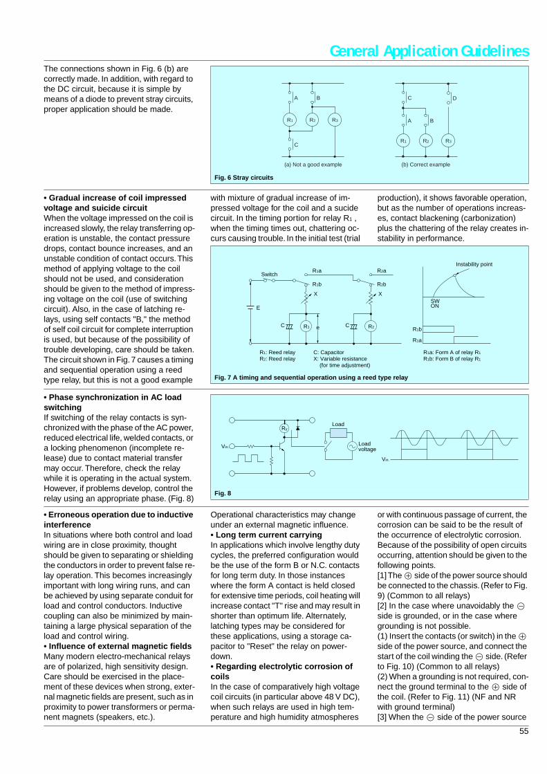
Fig. 6 shows an example of stray circuits. In Fig. 6 (a), with contacts A, B, and C closed, after relays R1, R2, and R3 oper-ate, if contacts B and C open, there is a series circuit through A, R1, R2, and R3, and the relays will hum and sometimes not be restored to the drop out condition.
Current passage time %
For continuous passage Temperature rise value is 100%
ON : OFF = 3 : 1 About 80%
ON : OFF = 1 : 1 About 50%
ON : OFF = 1 : 3 About 35%
1 : 1
Vol
tage
TimeFig. 4
Fig. 5 Example of a vertically written sequence circuit
R
Upper side line
Contact circuit
Load circuit
Lower side line
Power source lines
55
General Application GuidelinesThe connections shown in Fig. 6 (b) are correctly made. In addition, with regard to the DC circuit, because it is simple by means of a diode to prevent stray circuits, proper application should be made.
Fig. 6 Stray circuits
R1
A
C
B
R2 R3
R1
C D
A B
R2 R3
(a) Not a good example (b) Correct example
• Gradual increase of coil impressed voltage and suicide circuitWhen the voltage impressed on the coil is increased slowly, the relay transferring op-eration is unstable, the contact pressure drops, contact bounce increases, and an unstable condition of contact occurs. This method of applying voltage to the coil should not be used, and consideration should be given to the method of impress-ing voltage on the coil (use of switching circuit). Also, in the case of latching re-lays, using self contacts "B," the method of self coil circuit for complete interruption is used, but because of the possibility of trouble developing, care should be taken.The circuit shown in Fig. 7 causes a timing and sequential operation using a reed type relay, but this is not a good example
with mixture of gradual increase of im-pressed voltage for the coil and a sucide circuit. In the timing portion for relay R1 , when the timing times out, chattering oc-curs causing trouble. In the initial test (trial
production), it shows favorable operation, but as the number of operations increas-es, contact blackening (carbonization) plus the chattering of the relay creates in-stability in performance.
Fig. 7 A timing and sequential operation using a reed type relay
R1
R1b
E
C
X
R1a R2a
R2 R1b
R1a
R2b
C
XSWON
e
Switch
R1: Reed relayR2: Reed relay
R1a: Form A of relay R1
R1b: Form B of relay R1
C: CapacitorX: Variable resistance (for time adjustment)
Instability point
• Phase synchronization in AC load switchingIf switching of the relay contacts is syn-chronized with the phase of the AC power, reduced electrical life, welded contacts, or a locking phenomenon (incomplete re-lease) due to contact material transfer may occur. Therefore, check the relay while it is operating in the actual system. However, if problems develop, control the relay using an appropriate phase. (Fig. 8)
Fig. 8
Vin.
Vin.
RyLoad
Loadvoltage
• Erroneous operation due to inductive interferenceIn situations where both control and load wiring are in close proximity, thought should be given to separating or shielding the conductors in order to prevent false re-lay operation. This becomes increasingly important with long wiring runs, and can be achieved by using separate conduit for load and control conductors. Inductive coupling can also be minimized by main-taining a large physical separation of the load and control wiring.• Influence of external magnetic fieldsMany modern electro-mechanical relays are of polarized, high sensitivity design. Care should be exercised in the place-ment of these devices when strong, exter-nal magnetic fields are present, such as in proximity to power transformers or perma-nent magnets (speakers, etc.).
Operational characteristics may change under an external magnetic influence.• Long term current carryingIn applications which involve lengthy duty cycles, the preferred configuration would be the use of the form B or N.C. contacts for long term duty. In those instances where the form A contact is held closed for extensive time periods, coil heating will increase contact "T" rise and may result in shorter than optimum life. Alternately, latching types may be considered for these applications, using a storage ca-pacitor to "Reset" the relay on power-down.• Regarding electrolytic corrosion of coilsIn the case of comparatively high voltage coil circuits (in particular above 48 V DC), when such relays are used in high tem-perature and high humidity atmospheres
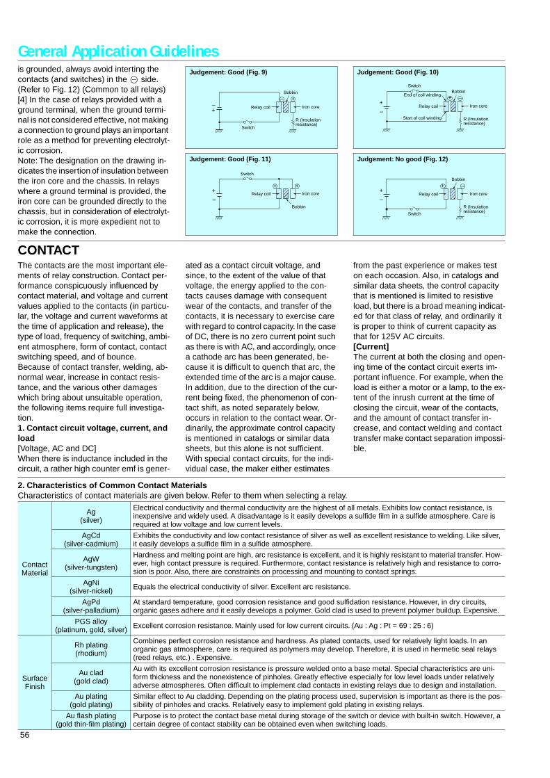
or with continuous passage of current, the corrosion can be said to be the result of the occurrence of electrolytic corrosion. Because of the possibility of open circuits occurring, attention should be given to the following points.[1] The B side of the power source should be connected to the chassis. (Refer to Fig. 9) (Common to all relays)[2] In the case where unavoidably the v side is grounded, or in the case where grounding is not possible.(1) Insert the contacts (or switch) in the B side of the power source, and connect the start of the coil winding the v side. (Refer to Fig. 10) (Common to all relays)(2) When a grounding is not required, con-nect the ground terminal to the B side of the coil. (Refer to Fig. 11) (NF and NR with ground terminal)[3] When the v side of the power source
56
General Application Guidelinesis grounded, always avoid interting the contacts (and switches) in the v side. (Refer to Fig. 12) (Common to all relays)[4] In the case of relays provided with a ground terminal, when the ground termi-nal is not considered effective, not making a connection to ground plays an important role as a method for preventing electrolyt-ic corrosion.Note: The designation on the drawing in-dicates the insertion of insulation between the iron core and the chassis. In relays where a ground terminal is provided, the iron core can be grounded directly to the chassis, but in consideration of electrolyt-ic corrosion, it is more expedient not to make the connection.
Judgement: Good (Fig. 9)
+
–
+–
Switch
Relay coil
Bobbin
Iron core
R (Insulationresistance)
Judgement: Good (Fig. 10)
+ –
+
–
Switch
Relay coil
End of coil winding
Start of coil winding
Bobbin
Iron core
R (Insulationresistance)
Judgement: Good (Fig. 11)
++
–
Switch
Relay coil
Bobbin
Iron core
+
Judgement: No good (Fig. 12)
++
–
–
Switch
Relay coil
Bobbin
Iron core
R (Insulationresistance)
CONTACTThe contacts are the most important ele-ments of relay construction. Contact per-formance conspicuously influenced by contact material, and voltage and current values applied to the contacts (in particu-lar, the voltage and current waveforms at the time of application and release), the type of load, frequency of switching, ambi-ent atmosphere, form of contact, contact switching speed, and of bounce.Because of contact transfer, welding, ab-normal wear, increase in contact resis-tance, and the various other damages which bring about unsuitable operation, the following items require full investiga-tion.1. Contact circuit voltage, current, and load[Voltage, AC and DC]When there is inductance included in the circuit, a rather high counter emf is gener-
ated as a contact circuit voltage, and since, to the extent of the value of that voltage, the energy applied to the con-tacts causes damage with consequent wear of the contacts, and transfer of the contacts, it is necessary to exercise care with regard to control capacity. In the case of DC, there is no zero current point such as there is with AC, and accordingly, once a cathode arc has been generated, be-cause it is difficult to quench that arc, the extended time of the arc is a major cause. In addition, due to the direction of the cur-rent being fixed, the phenomenon of con-tact shift, as noted separately below, occurs in relation to the contact wear. Or-dinarily, the approximate control capacity is mentioned in catalogs or similar data sheets, but this alone is not sufficient. With special contact circuits, for the indi-vidual case, the maker either estimates
from the past experience or makes test on each occasion. Also, in catalogs and similar data sheets, the control capacity that is mentioned is limited to resistive load, but there is a broad meaning indicat-ed for that class of relay, and ordinarily it is proper to think of current capacity as that for 125V AC circuits.[Current]The current at both the closing and open-ing time of the contact circuit exerts im-portant influence. For example, when the load is either a motor or a lamp, to the ex-tent of the inrush current at the time of closing the circuit, wear of the contacts, and the amount of contact transfer in-crease, and contact welding and contact transfer make contact separation impossi-ble.
2. Characteristics of Common Contact MaterialsCharacteristics of contact materials are given below. Refer to them when selecting a relay.
Contact Material
Ag(silver)
Electrical conductivity and thermal conductivity are the highest of all metals. Exhibits low contact resistance, is inexpensive and widely used. A disadvantage is it easily develops a sulfide film in a sulfide atmosphere. Care is required at low voltage and low current levels.
AgCd(silver-cadmium)
Exhibits the conductivity and low contact resistance of silver as well as excellent resistance to welding. Like silver, it easily develops a sulfide film in a sulfide atmosphere.
AgW(silver-tungsten)
Hardness and melting point are high, arc resistance is excellent, and it is highly resistant to material transfer. How-ever, high contact pressure is required. Furthermore, contact resistance is relatively high and resistance to corro-sion is poor. Also, there are constraints on processing and mounting to contact springs.
AgNi(silver-nickel) Equals the electrical conductivity of silver. Excellent arc resistance.
AgPd(silver-palladium)
At standard temperature, good corrosion resistance and good sulfidation resistance. However, in dry circuits, organic gases adhere and it easily develops a polymer. Gold clad is used to prevent polymer buildup. Expensive.
PGS alloy(platinum, gold, silver) Excellent corrosion resistance. Mainly used for low current circuits. (Au : Ag : Pt = 69 : 25 : 6)
Surface Finish
Rh plating(rhodium)
Combines perfect corrosion resistance and hardness. As plated contacts, used for relatively light loads. In an organic gas atmosphere, care is required as polymers may develop. Therefore, it is used in hermetic seal relays (reed relays, etc.) . Expensive.
Au clad(gold clad)
Au with its excellent corrosion resistance is pressure welded onto a base metal. Special characteristics are uni-form thickness and the nonexistence of pinholes. Greatly effective especially for low level loads under relatively adverse atmospheres. Often difficult to implement clad contacts in existing relays due to design and installation.
Au plating(gold plating)
Similar effect to Au cladding. Depending on the plating process used, supervision is important as there is the pos-sibility of pinholes and cracks. Relatively easy to implement gold plating in existing relays.
Au flash plating(gold thin-film plating)
Purpose is to protect the contact base metal during storage of the switch or device with built-in switch. However, a certain degree of contact stability can be obtained even when switching loads.
57
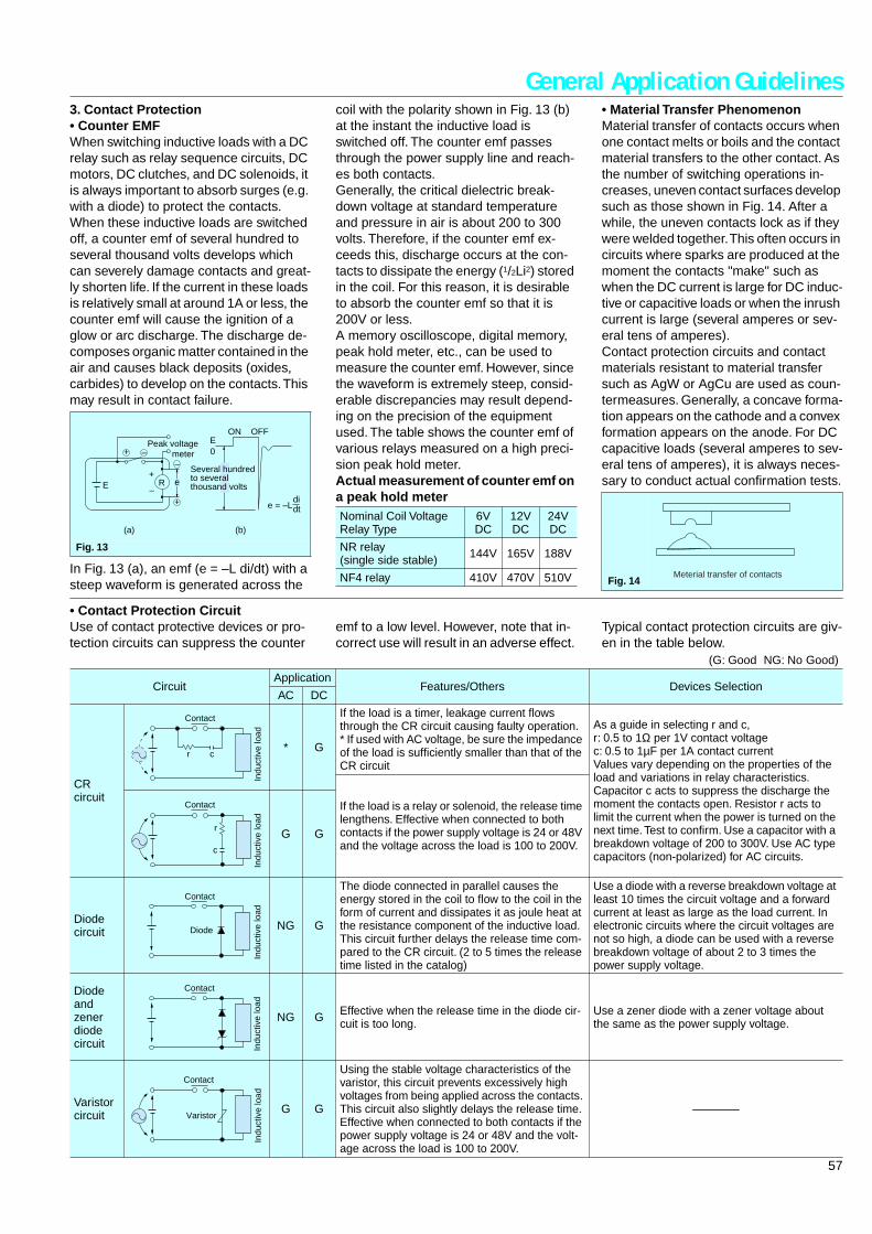
General Application Guidelines3. Contact Protection• Counter EMFWhen switching inductive loads with a DC relay such as relay sequence circuits, DC motors, DC clutches, and DC solenoids, it is always important to absorb surges (e.g. with a diode) to protect the contacts.When these inductive loads are switched off, a counter emf of several hundred to several thousand volts develops which can severely damage contacts and great-ly shorten life. If the current in these loads is relatively small at around 1A or less, the counter emf will cause the ignition of a glow or arc discharge. The discharge de-composes organic matter contained in the air and causes black deposits (oxides, carbides) to develop on the contacts. This may result in contact failure.
In Fig. 13 (a), an emf (e = –L di/dt) with a steep waveform is generated across the
coil with the polarity shown in Fig. 13 (b) at the instant the inductive load is switched off. The counter emf passes through the power supply line and reach-es both contacts.Generally, the critical dielectric break-down voltage at standard temperature and pressure in air is about 200 to 300 volts. Therefore, if the counter emf ex-ceeds this, discharge occurs at the con-tacts to dissipate the energy (1/2Li2) stored in the coil. For this reason, it is desirable to absorb the counter emf so that it is 200V or less.A memory oscilloscope, digital memory, peak hold meter, etc., can be used to measure the counter emf. However, since the waveform is extremely steep, consid-erable discrepancies may result depend-ing on the precision of the equipment used. The table shows the counter emf of various relays measured on a high preci-sion peak hold meter.Actual measurement of counter emf on a peak hold meter
• Material Transfer PhenomenonMaterial transfer of contacts occurs when one contact melts or boils and the contact material transfers to the other contact. As the number of switching operations in-creases, uneven contact surfaces develop such as those shown in Fig. 14. After a while, the uneven contacts lock as if they were welded together. This often occurs in circuits where sparks are produced at the moment the contacts "make" such as when the DC current is large for DC induc-tive or capacitive loads or when the inrush current is large (several amperes or sev-eral tens of amperes).Contact protection circuits and contact materials resistant to material transfer such as AgW or AgCu are used as coun-termeasures. Generally, a concave forma-tion appears on the cathode and a convex formation appears on the anode. For DC capacitive loads (several amperes to sev-eral tens of amperes), it is always neces-sary to conduct actual confirmation tests.
Fig. 13
E
EON OFF
0
didt
R e
e = –L
+
+
–
–
(a) (b)
Peak voltage meter
Several hundredto severalthousand volts
+
–
Nominal Coil VoltageRelay Type
6V DC
12V DC
24V DC
NR relay(single side stable) 144V 165V 188V
NF4 relay 410V 470V 510V Fig. 14Meterial transfer of contacts
• Contact Protection CircuitUse of contact protective devices or pro-tection circuits can suppress the counter
emf to a low level. However, note that in-correct use will result in an adverse effect.
Typical contact protection circuits are giv-en in the table below.
(G: Good NG: No Good)
CircuitApplication
Features/Others Devices SelectionAC DC
CR circuit
* G
If the load is a timer, leakage current flows through the CR circuit causing faulty operation.* If used with AC voltage, be sure the impedance of the load is sufficiently smaller than that of the CR circuit
As a guide in selecting r and c,r: 0.5 to 1Ω per 1V contact voltagec: 0.5 to 1µF per 1A contact currentValues vary depending on the properties of the load and variations in relay characteristics. Capacitor c acts to suppress the discharge the moment the contacts open. Resistor r acts to limit the current when the power is turned on the next time. Test to confirm. Use a capacitor with a breakdown voltage of 200 to 300V. Use AC type capacitors (non-polarized) for AC circuits.
If the load is a relay or solenoid, the release time lengthens. Effective when connected to both contacts if the power supply voltage is 24 or 48V and the voltage across the load is 100 to 200V.
G G
Diode circuit NG G
The diode connected in parallel causes the energy stored in the coil to flow to the coil in the form of current and dissipates it as joule heat at the resistance component of the inductive load. This circuit further delays the release time com-pared to the CR circuit. (2 to 5 times the release time listed in the catalog)
Use a diode with a reverse breakdown voltage at least 10 times the circuit voltage and a forward current at least as large as the load current. In electronic circuits where the circuit voltages are not so high, a diode can be used with a reverse breakdown voltage of about 2 to 3 times the power supply voltage.
Diode and zener diode circuit
NG G Effective when the release time in the diode cir-cuit is too long.
Use a zener diode with a zener voltage about the same as the power supply voltage.
Varistor circuit G G
Using the stable voltage characteristics of the varistor, this circuit prevents excessively high voltages from being applied across the contacts. This circuit also slightly delays the release time. Effective when connected to both contacts if the power supply voltage is 24 or 48V and the volt-age across the load is 100 to 200V.
—
r c
Contact
Indu
ctiv
e lo
ad
r
c
Contact
Indu
ctiv
e lo
ad
Contact
Indu
ctiv
e lo
ad
Diode
Contact
Indu
ctiv
e lo
ad
Contact
Indu
ctiv
e lo
ad
Varistor
58
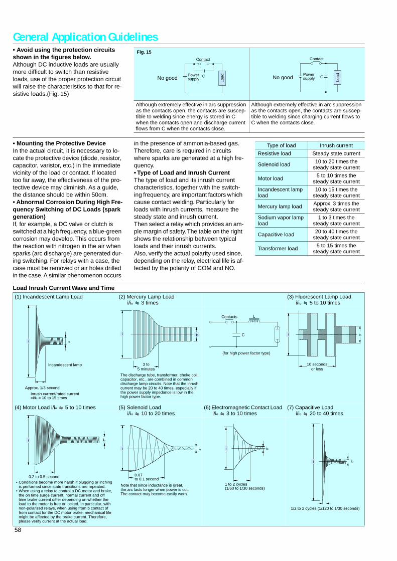
General Application Guidelines• Avoid using the protection circuits shown in the figures below.Although DC inductive loads are usually more difficult to switch than resistive loads, use of the proper protection circuit will raise the characteristics to that for re-sistive loads.(Fig. 15)
Fig. 15
Although extremely effective in arc suppression as the contacts open, the contacts are suscep-tible to welding since energy is stored in C when the contacts open and discharge current flows from C when the contacts close.
Although extremely effective in arc suppression as the contacts open, the contacts are suscep-tible to welding since charging current flows to C when the contacts close.
Contact
Powersupply Lo
adNo good C
Contact
Powersupply Lo
adNo good C
• Mounting the Protective DeviceIn the actual circuit, it is necessary to lo-cate the protective device (diode, resistor, capacitor, varistor, etc.) in the immediate vicinity of the load or contact. If located too far away, the effectiveness of the pro-tective device may diminish. As a guide, the distance should be within 50cm.• Abnormal Corrosion During High Fre-quency Switching of DC Loads (spark generation)If, for example, a DC valve or clutch is switched at a high frequency, a blue-green corrosion may develop. This occurs from the reaction with nitrogen in the air when sparks (arc discharge) are generated dur-ing switching. For relays with a case, the case must be removed or air holes drilled in the case. A similar phenomenon occurs
in the presence of ammonia-based gas. Therefore, care is required in circuits where sparks are generated at a high fre-quency.• Type of Load and Inrush CurrentThe type of load and its inrush current characteristics, together with the switch-ing frequency, are important factors which cause contact welding. Particularly for loads with inrush currents, measure the steady state and inrush current.Then select a relay which provides an am-ple margin of safety. The table on the right shows the relationship between typical loads and their inrush currents.Also, verify the actual polarity used since, depending on the relay, electrical life is af-fected by the polarity of COM and NO.
Type of load Inrush current
Resistive load Steady state current
Solenoid load 10 to 20 times the steady state current
Motor load 5 to 10 times the steady state current
Incandescent lamp load
10 to 15 times the steady state current
Mercury lamp load Approx. 3 times the steady state current
Sodium vapor lamp load
1 to 3 times the steady state current
Capacitive load 20 to 40 times the steady state current
Transformer load 5 to 15 times the steady state current
Load Inrush Current Wave and Time(1) Incandescent Lamp Load (2) Mercury Lamp Load
i/io ] 3 times(3) Fluorescent Lamp Load
i/io ] 5 to 10 times
(4) Motor Load i/io ] 5 to 10 times (5) Solenoid Load i/io ] 10 to 20 times
(6) Electromagnetic Contact Load i/io ] 3 to 10 times
(7) Capacitive Load i/io ] 20 to 40 times
i
Approx. 1/3 second
Inrush current/rated current=i/io = 10 to 15 times
Incandescent lamp
io
i io
3 to5 minutes
The discharge tube, transformer, choke coil, capacitor, etc., are combined in common discharge lamp circuits. Note that the inrush current may be 20 to 40 times, especially if the power supply impedance is low in the high power factor type.
Contacts L
C
(for high power factor type)
ioi
10 secondsor less
ioi
0.2 to 0.5 second• Conditions become more harsh if plugging or inching
is performed since state transitions are repeated.• When using a relay to control a DC motor and brake,
the on time surge current, normal current and off time brake current differ depending on whether the load to the motor is free or locked. In particular, with non-polarized relays, when using from b contact of from contact for the DC motor brake, mechanical life might be affected by the brake current. Therefore, please verify current at the actual load.
io
0.07to 0.1 second
i
Note that since inductance is great, the arc lasts longer when power is cut. The contact may become easily worn.
io
1 to 2 cycles(1/60 to 1/30 seconds)
i
io
1/2 to 2 cycles (1/120 to 1/30 seconds)
i
59
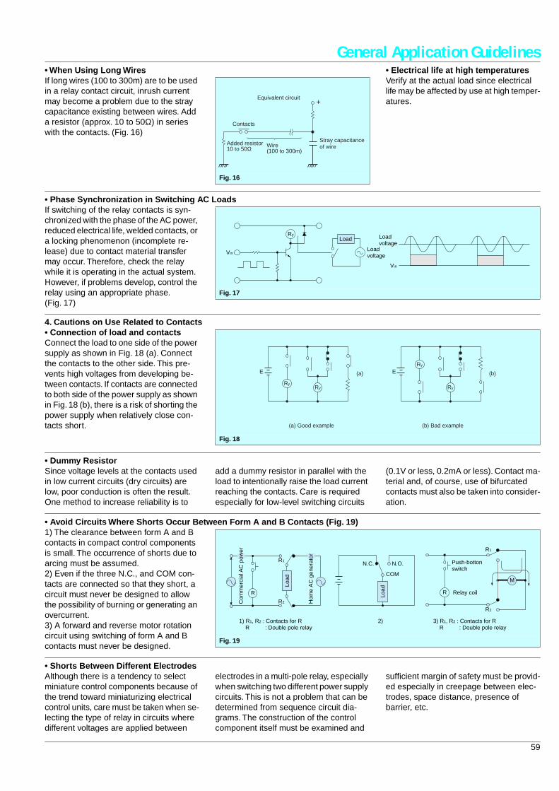
General Application Guidelines• When Using Long WiresIf long wires (100 to 300m) are to be used in a relay contact circuit, inrush current may become a problem due to the stray capacitance existing between wires. Add a resistor (approx. 10 to 50Ω) in series with the contacts. (Fig. 16)
• Electrical life at high temperaturesVerify at the actual load since electrical life may be affected by use at high temper-atures.
Fig. 16
Contacts
Added resistor10 to 50Ω Wire
(100 to 300m)
Stray capacitanceof wire
Equivalent circuit+
• Phase Synchronization in Switching AC LoadsIf switching of the relay contacts is syn-chronized with the phase of the AC power, reduced electrical life, welded contacts, or a locking phenomenon (incomplete re-lease) due to contact material transfer may occur. Therefore, check the relay while it is operating in the actual system. However, if problems develop, control the relay using an appropriate phase. (Fig. 17)
Fig. 17
Vin
Vin
RyLoad
Loadvoltage
Loadvoltage
4. Cautions on Use Related to Contacts• Connection of load and contactsConnect the load to one side of the power supply as shown in Fig. 18 (a). Connect the contacts to the other side. This pre-vents high voltages from developing be-tween contacts. If contacts are connected to both side of the power supply as shown in Fig. 18 (b), there is a risk of shorting the power supply when relatively close con-tacts short.
Fig. 18
Ry
E (a)
Ry
Ry
E (b)
Ry
(a) Good example (b) Bad example
• Dummy ResistorSince voltage levels at the contacts used in low current circuits (dry circuits) are low, poor conduction is often the result. One method to increase reliability is to
add a dummy resistor in parallel with the load to intentionally raise the load current reaching the contacts. Care is required especially for low-level switching circuits
(0.1V or less, 0.2mA or less). Contact ma-terial and, of course, use of bifurcated contacts must also be taken into consider-ation.
• Avoid Circuits Where Shorts Occur Between Form A and B Contacts (Fig. 19)1) The clearance between form A and B contacts in compact control components is small. The occurrence of shorts due to arcing must be assumed.2) Even if the three N.C., and COM con-tacts are connected so that they short, a circuit must never be designed to allow the possibility of burning or generating an overcurrent.3) A forward and reverse motor rotation circuit using switching of form A and B contacts must never be designed.
Fig. 19
R
COM
R2
R1
R2
R1N.O.N.C.
R
M
Com
mer
cial
AC
pow
er
Load
Load
Hom
e A
C g
ener
ator
Push-bottonswitch
Relay coil
1) R1, R2 : Contacts for R R : Double pole relay
3) R1, R2 : Contacts for R R : Double pole relay
2)
• Shorts Between Different ElectrodesAlthough there is a tendency to select miniature control components because of the trend toward miniaturizing electrical control units, care must be taken when se-lecting the type of relay in circuits where different voltages are applied between
electrodes in a multi-pole relay, especially when switching two different power supply circuits. This is not a problem that can be determined from sequence circuit dia-grams. The construction of the control component itself must be examined and
sufficient margin of safety must be provid-ed especially in creepage between elec-trodes, space distance, presence of barrier, etc.
60
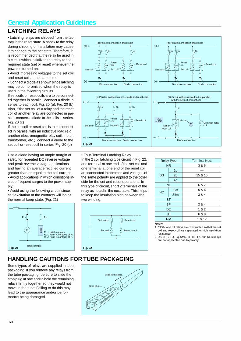
General Application GuidelinesLATCHING RELAYS• Latching relays are shipped from the fac-tory in the reset state. A shock to the relay during shipping or installation may cause it to change to the set state. Therefore, it is recommended that the relay be used in a circuit which initializes the relay to the required state (set or reset) whenever the power is turned on.• Avoid impressing voltages to the set coil and reset coil at the same time.• Connect a diode as shown since latching may be compromised when the relay is used in the following circuits.If set coils or reset coils are to be connect-ed together in parallel, connect a diode in series to each coil. Fig. 20 (a), Fig. 20 (b) Also, if the set coil of a relay and the reset coil of another relay are connected in par-allel, connect a diode to the coils in series. Fig. 20 (c)If the set coil or reset coil is to be connect-ed in parallel with an inductive load (e.g. another electromagnetic relay coil, motor, transformer, etc.), connect a diode to the set coil or reset coil in series. Fig. 20 (d) Fig. 20
S2S1 S3
(a) Parallel connection of set coils(+)
(–)
Set coil
Resetcoil
Set coil
Reset coil
Diode connection Diode connection
S2S1 S3
(b) Parallel connection of set coils
Set coil
Resetcoil
Set coil
Reset coil
Diode connection Diode connection
(+)
(–)
S2S1 S3
(c) Parallel connection of set coils and reset coils
(+)
(–)
Set coil
Resetcoil
Set coil
Reset coil
Diode connection Diode connection
M
S
(d) Circuit with inductive load in parallel with the set coil or reset coil
(+)
(–)
Set orreset coil
MotorCommon relaycoil
Diode connection
ACor DC
Use a diode having an ample margin of safety for repeated DC reverse voltage and peak reverse voltage applications and having an average rectified current greater than or equal to the coil current.• Avoid applications in which conditions in-clude frequent surges to the power sup-ply.• Avoid using the following circuit since self-excitation at the contacts will inhibit the normal keep state. (Fig. 21)
• Four-Terminal Latching RelayIn the 2 coil latching type circuit in Fig. 22, one terminal at one end of the set coil and one terminal at one end of the reset coil are connected in common and voltages of the same polarity are applied to the other side for the set and reset operations. In this type of circuit, short 2 terminals of the relay as noted in the next table. This helps to keep the insulation high between the two winding.
Notes:1. *DS4c and ST relays are constructed so that the set
coil and reset coil are separated for high insulation resistance.
2. DSP, RG, TQ, TQ-SMD, TF, TN, TX, and SEB relays are not applicable due to polarity.
RL
RLb RLa
RL : Latching relayRLa : Form A contacts of RL
RLb : Form B contacts of RL
Bad example
Load
Fig. 21 Fig. 22
Set switch
Set coil
Reset coil
Reset switch
Relay Type Terminal Nos.
NR 3 & 6
DS
1c —
2c 15 & 16
4c *
NL 6 & 7
NCFlat 5 & 6
Slim 3 & 4
ST *
SP 2 & 4
DE 1 & 2
JH 6 & 8
RM 1 & 12
HANDLING CAUTIONS FOR TUBE PACKAGINGSome types of relays are supplied in tube packaging. If you remove any relays from the tube packaging, be sure to slide the stop plug at one end to hold the remaining relays firmly together so they would not move in the tube. Failing to do this may lead to the appearance and/or perfor-mance being damaged.
Slide in the plug.
Stop plug
61
General Application GuidelinesAMBIENT ENVIRONMENT1. Ambient Temperature and AtmosphereBe sure the ambient temperature at the installation does not exceed the value list-ed in the catalog. Furthermore, environ-mentally sealed types (plastic sealed type, metallic hermetic seal type) should be considered for applications in an atmo-sphere with dust, sulfur gases (SO2, H2 S), or organic gases.2. Silicon AtmosphereSilicon-based substances (silicon rubber, silicon oil, silicon-based coating material, silicon caulking compound, etc.) emit vol-atile silicon gas. Note that when silicon is used near relay, switching the contacts in the presence of its gas causes silicon to adhere to the contacts and may result in contact failure.In this case, use a substitute that is not sil-icon-based.3. Vibration and ShockIf a relay and magnetic switch are mount-ed next to each other on a single plate, the relay contacts may separate momentarily from the shock produced when the mag-netic switch is operated and result in faulty operation. Countermeasures include mounting them on separate plates, using a rubber sheet to absorb the shock, and changing the direction of the shock to a perpendicular angle.
4. Influence of External Magnetic FieldsPermanent magnets are used in reed re-lays and polarized relays (including NR relays), and their movable parts are con-structed of ferrous materials. For this rea-son, when a magnet or permanent magnet in any other large relay, trans-former, or speaker is located nearby, the relay characteristics may change and faulty operations may result. The influ-ence depends on the strength of the mag-netic field and it should be checked at the installation.5. Usage, storage, and transport condi-tions1) During usage, storage, or transporta-tion, avoid locations subject to direct sun-light and maintain normal temperature, humidity, and pressure conditions.The allowable specifications for environ-ments suitable for usage, storage, and transportation are given below.• Temperature: The allowable temperature range differs for each relay, so refer to the relay's individual specifications.In addition, when transporting or storing relays while they are tube packaged, there are cases when the temperature may differ from the allowable range.In this situation, be sure to consult the in-dividual specifications.
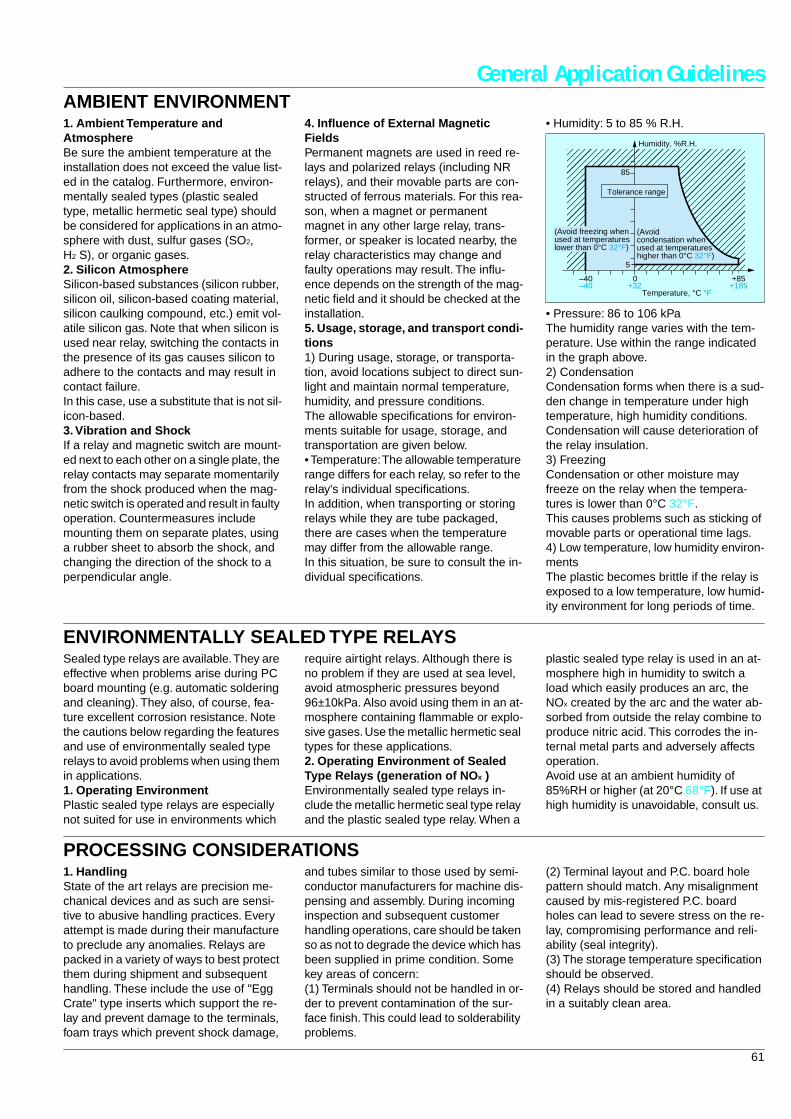
• Humidity: 5 to 85 % R.H.
• Pressure: 86 to 106 kPaThe humidity range varies with the tem-perature. Use within the range indicated in the graph above.2) CondensationCondensation forms when there is a sud-den change in temperature under high temperature, high humidity conditions.Condensation will cause deterioration of the relay insulation.3) FreezingCondensation or other moisture may freeze on the relay when the tempera-tures is lower than 0°C 32°F.This causes problems such as sticking of movable parts or operational time lags.4) Low temperature, low humidity environ-mentsThe plastic becomes brittle if the relay is exposed to a low temperature, low humid-ity environment for long periods of time.
Tolerance range
(Avoidcondensation whenused at temperatureshigher than 0°C 32°F)
(Avoid freezing whenused at temperatureslower than 0°C 32°F)
85
5
–40–40
0+32
+85+185
Temperature, °C °F
Humidity, %R.H.
ENVIRONMENTALLY SEALED TYPE RELAYSSealed type relays are available. They are effective when problems arise during PC board mounting (e.g. automatic soldering and cleaning). They also, of course, fea-ture excellent corrosion resistance. Note the cautions below regarding the features and use of environmentally sealed type relays to avoid problems when using them in applications.1. Operating EnvironmentPlastic sealed type relays are especially not suited for use in environments which
require airtight relays. Although there is no problem if they are used at sea level, avoid atmospheric pressures beyond 96±10kPa. Also avoid using them in an at-mosphere containing flammable or explo-sive gases. Use the metallic hermetic seal types for these applications.2. Operating Environment of Sealed Type Relays (generation of NO x )Environmentally sealed type relays in-clude the metallic hermetic seal type relay and the plastic sealed type relay. When a
plastic sealed type relay is used in an at-mosphere high in humidity to switch a load which easily produces an arc, the NOx created by the arc and the water ab-sorbed from outside the relay combine to produce nitric acid. This corrodes the in-ternal metal parts and adversely affects operation.Avoid use at an ambient humidity of 85%RH or higher (at 20°C 68°F). If use at high humidity is unavoidable, consult us.
PROCESSING CONSIDERATIONS1. HandlingState of the art relays are precision me-chanical devices and as such are sensi-tive to abusive handling practices. Every attempt is made during their manufacture to preclude any anomalies. Relays are packed in a variety of ways to best protect them during shipment and subsequent handling. These include the use of "Egg Crate" type inserts which support the re-lay and prevent damage to the terminals, foam trays which prevent shock damage,
and tubes similar to those used by semi-conductor manufacturers for machine dis-pensing and assembly. During incoming inspection and subsequent customer handling operations, care should be taken so as not to degrade the device which has been supplied in prime condition. Some key areas of concern:(1) Terminals should not be handled in or-der to prevent contamination of the sur-face finish. This could lead to solderability problems.
(2) Terminal layout and P.C. board hole pattern should match. Any misalignment caused by mis-registered P.C. board holes can lead to severe stress on the re-lay, compromising performance and reli-ability (seal integrity).(3) The storage temperature specification should be observed.(4) Relays should be stored and handled in a suitably clean area.
62
General Application Guidelines2. FluxingDepending upon the type of relay in-volved, fluxing procedures should be re-searched carefully. An unsealed relay is prone to internal flux contamination which can compromise contact performance, and ideally should be hand soldered. "Flux-resistant" relays are available which will prevent flux migration through the ter-minal-header interface. These and "sealed" relays are compatible with mist foam or spray fluxing operations, however "Flux-resistant" types are not totally sealed which precludes washing opera-tions, and makes a non-active flux almost a necessity.Pre-heating the board assembly prior to soldering "Flux-resistant" types will dry
the flux and further help to prevent flux be-ing driven into the relay during the solder-ing operation.3. SolderingAs with fluxing, automated soldering pro-cesses can, unless controlled carefully, compromise the performance of unsealed relays.Flux-resistant and sealed types are com-patible with mist dip or wave soldering procedures. Some state-of-the-art relays are suitable for various reflow processes, such as I.R. or vapor phase maximum sol-dering temperatures and times will vary from relay type to relay type, and should not be exceeded. The use of an I.R. reflow process with a relay not specifically de-signed to withstand the process, will in all
probability degrade the relay and cause performance problems. A safe practice would be to review the thermal profile of the process on a case by case basis with your local Matsushita office.4. CleaningAny cleaning process which involves po-tential contamination of an unsealed relay should be avoided. Sealed devices can be immersion cleaned in a suitable solvent (see solvent compatibility chart). Cleaning in a ultrasonic bath should also be avoid-ed. A harmonic of the bath frequency may be induced in the contacts causing friction welding and subsequent contact sticking. Relays with a removable "vent" tab should be vented after cooling to room tempera-ture following cleaning and drying.
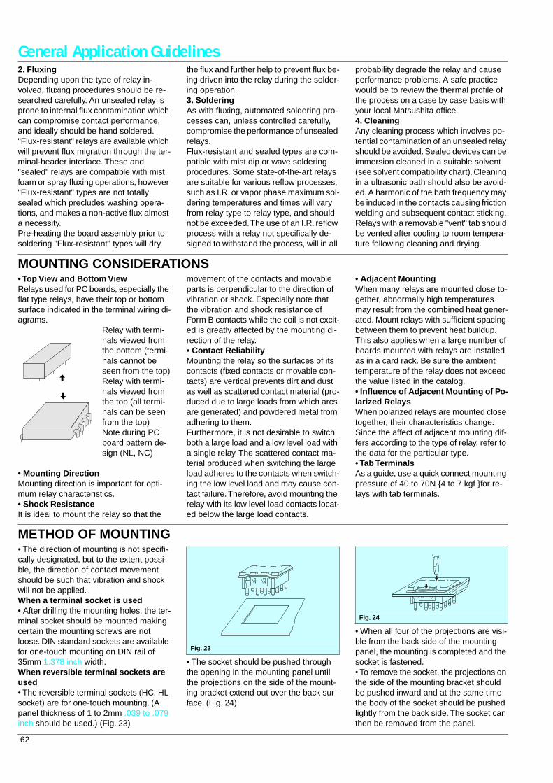
MOUNTING CONSIDERATIONS• Top View and Bottom ViewRelays used for PC boards, especially the flat type relays, have their top or bottom surface indicated in the terminal wiring di-agrams.
• Mounting DirectionMounting direction is important for opti-mum relay characteristics.• Shock ResistanceIt is ideal to mount the relay so that the
movement of the contacts and movable parts is perpendicular to the direction of vibration or shock. Especially note that the vibration and shock resistance of Form B contacts while the coil is not excit-ed is greatly affected by the mounting di-rection of the relay.• Contact ReliabilityMounting the relay so the surfaces of its contacts (fixed contacts or movable con-tacts) are vertical prevents dirt and dust as well as scattered contact material (pro-duced due to large loads from which arcs are generated) and powdered metal from adhering to them.Furthermore, it is not desirable to switch both a large load and a low level load with a single relay. The scattered contact ma-terial produced when switching the large load adheres to the contacts when switch-ing the low level load and may cause con-tact failure. Therefore, avoid mounting the relay with its low level load contacts locat-ed below the large load contacts.
• Adjacent MountingWhen many relays are mounted close to-gether, abnormally high temperatures may result from the combined heat gener-ated. Mount relays with sufficient spacing between them to prevent heat buildup.This also applies when a large number of boards mounted with relays are installed as in a card rack. Be sure the ambient temperature of the relay does not exceed the value listed in the catalog.• Influence of Adjacent Mounting of Po-larized RelaysWhen polarized relays are mounted close together, their characteristics change. Since the affect of adjacent mounting dif-fers according to the type of relay, refer to the data for the particular type.• Tab TerminalsAs a guide, use a quick connect mounting pressure of 40 to 70N 4 to 7 kgf for re-lays with tab terminals.
Relay with termi-nals viewed from the bottom (termi-nals cannot be seen from the top)Relay with termi-nals viewed from the top (all termi-nals can be seen from the top)Note during PC board pattern de-sign (NL, NC)
METHOD OF MOUNTING• The direction of mounting is not specifi-cally designated, but to the extent possi-ble, the direction of contact movement should be such that vibration and shock will not be applied.When a terminal socket is used• After drilling the mounting holes, the ter-minal socket should be mounted making certain the mounting screws are not loose. DIN standard sockets are available for one-touch mounting on DIN rail of 35mm 1.378 inch width.When reversible terminal sockets are used• The reversible terminal sockets (HC, HL socket) are for one-touch mounting. (A panel thickness of 1 to 2mm .039 to .079 inch should be used.) (Fig. 23)
• The socket should be pushed through the opening in the mounting panel until the projections on the side of the mount-ing bracket extend out over the back sur-face. (Fig. 24)
• When all four of the projections are visi-ble from the back side of the mounting panel, the mounting is completed and the socket is fastened.• To remove the socket, the projections on the side of the mounting bracket should be pushed inward and at the same time the body of the socket should be pushed lightly from the back side. The socket can then be removed from the panel.
Fig. 23
Fig. 24
63
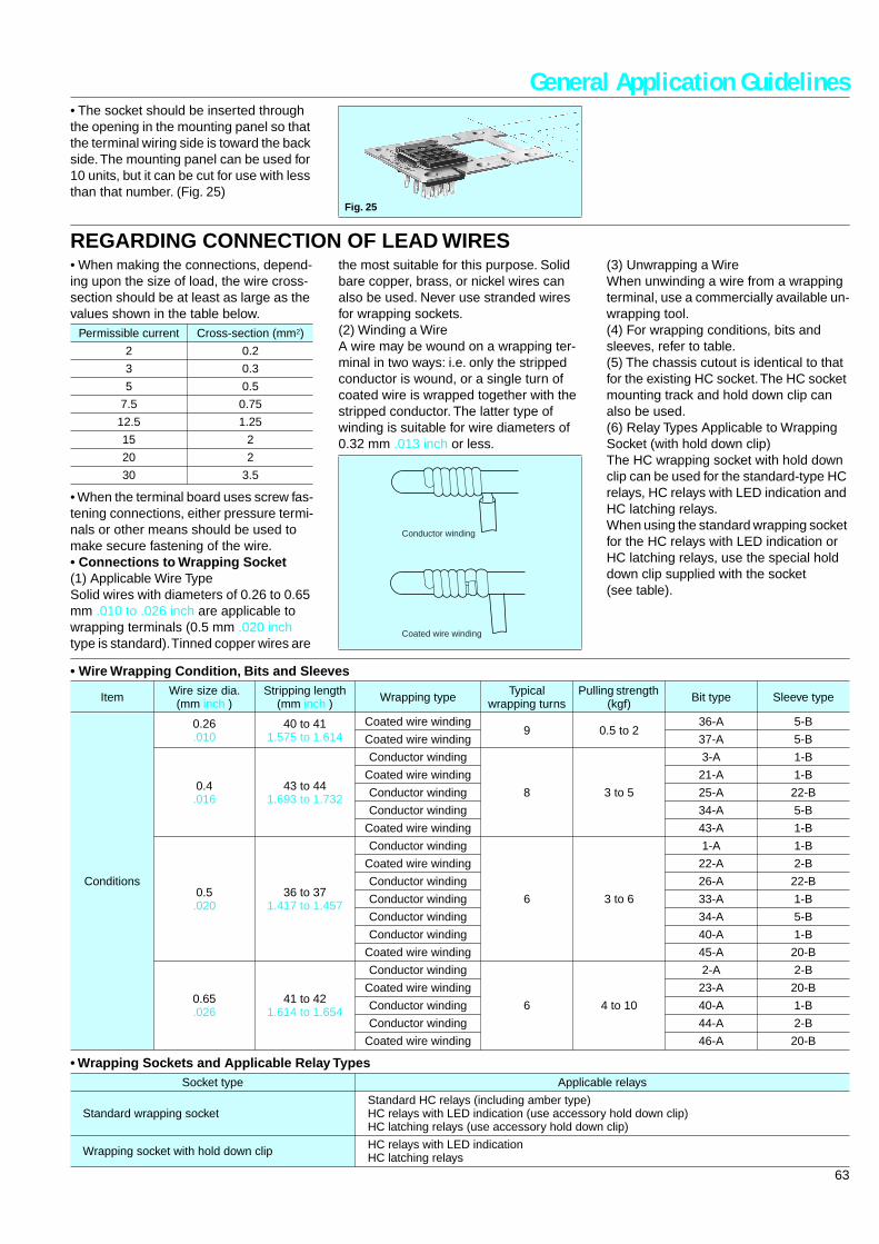
General Application Guidelines• The socket should be inserted through the opening in the mounting panel so that the terminal wiring side is toward the back side. The mounting panel can be used for 10 units, but it can be cut for use with less than that number. (Fig. 25)
Fig. 25
REGARDING CONNECTION OF LEAD WIRES• When making the connections, depend-ing upon the size of load, the wire cross-section should be at least as large as the values shown in the table below.
• When the terminal board uses screw fas-tening connections, either pressure termi-nals or other means should be used to make secure fastening of the wire.• Connections to Wrapping Socket(1) Applicable Wire TypeSolid wires with diameters of 0.26 to 0.65 mm .010 to .026 inch are applicable to wrapping terminals (0.5 mm .020 inch type is standard). Tinned copper wires are
the most suitable for this purpose. Solid bare copper, brass, or nickel wires can also be used. Never use stranded wires for wrapping sockets.(2) Winding a WireA wire may be wound on a wrapping ter-minal in two ways: i.e. only the stripped conductor is wound, or a single turn of coated wire is wrapped together with the stripped conductor. The latter type of winding is suitable for wire diameters of 0.32 mm .013 inch or less.
(3) Unwrapping a WireWhen unwinding a wire from a wrapping terminal, use a commercially available un-wrapping tool.(4) For wrapping conditions, bits and sleeves, refer to table.(5) The chassis cutout is identical to that for the existing HC socket. The HC socket mounting track and hold down clip can also be used.(6) Relay Types Applicable to Wrapping Socket (with hold down clip)The HC wrapping socket with hold down clip can be used for the standard-type HC relays, HC relays with LED indication and HC latching relays.When using the standard wrapping socket for the HC relays with LED indication or HC latching relays, use the special hold down clip supplied with the socket (see table).
Permissible current Cross-section (mm2)
2 0.2
3 0.3
5 0.5
7.5 0.75
12.5 1.25
15 2
20 2
30 3.5
Conductor winding
Coated wire winding
• Wire Wrapping Condition, Bits and Sleeves
• Wrapping Sockets and Applicable Relay Types
Item Wire size dia. (mm inch )
Stripping length (mm inch ) Wrapping type Typical
wrapping turnsPulling strength
(kgf) Bit type Sleeve type
Conditions
0.26.010
40 to 411.575 to 1.614
Coated wire winding9 0.5 to 2
36-A 5-B
Coated wire winding 37-A 5-B
0.4.016
43 to 441.693 to 1.732
Conductor winding
8 3 to 5
3-A 1-B
Coated wire winding 21-A 1-B
Conductor winding 25-A 22-B
Conductor winding 34-A 5-B
Coated wire winding 43-A 1-B
0.5.020
36 to 371.417 to 1.457
Conductor winding
6 3 to 6
1-A 1-B
Coated wire winding 22-A 2-B
Conductor winding 26-A 22-B
Conductor winding 33-A 1-B
Conductor winding 34-A 5-B
Conductor winding 40-A 1-B
Coated wire winding 45-A 20-B
0.65.026
41 to 421.614 to 1.654
Conductor winding
6 4 to 10
2-A 2-B
Coated wire winding 23-A 20-B
Conductor winding 40-A 1-B
Conductor winding 44-A 2-B
Coated wire winding 46-A 20-B
Socket type Applicable relays
Standard wrapping socketStandard HC relays (including amber type)HC relays with LED indication (use accessory hold down clip)HC latching relays (use accessory hold down clip)
Wrapping socket with hold down clip HC relays with LED indicationHC latching relays
64
General Application GuidelinesCAUTIONS FOR USE–Check List
Check Item
Coil Drive Input
1.2.3.4.5.
6.7.8.
Is the correct rated voltage applied?Is the applied coil voltage within the allowable continuous voltage limit?Is the ripple in the coil voltage within the allowable level?For voltage applied to a polarized coil, is polarity observed?When hot start is required, is the increase in coil resistance resulting from coil temperature rise taken into account in set-ting coil voltage?Is the coil voltage free from momentary drop caused by load current? (Pay special attention for self-holding relays.)Is supply voltage fluctuation taken into account when setting the rated coil voltage?The relay status may become unstable if the coil voltage (current) is gradually increased or decreased. Was the relay tested in a real circuit or with a real load?
Load(Relay contacts)
1.2.3.4.
5.6.
7.
8.9.
10.11.
12.
Is the load rated within the contact ratings?Does the load exceed the contacts' minimum switching capacity?Special attention is required for contact welding when the load is a lamp, motor, solenoid, or electromagnetic contractor.Was the relay tested with a real load?A DC load may cause contact lock-up due to large contact transfer. Was the relay tested with a real load?For an inductive load, is a surge absorber used across the contacts?When an inductive load causes heavy arc discharge across the relay contacts, the contacts may be corroded by chemical reaction with nitrogen in the atmosphere. Was the relay tested with a real load?Platinum contacts may generate brown powder due to a catalyzer effect or vibration energy. Was the relay tested with a real load?Is the contact switching frequency below the specification?When there are more than two sets of contacts (2T) in a relay, metallic powder shed from one set of contacts may cause a contact failure on the other set (particularly for light loads). Was the relay tested in a real circuit?A delay capacitor used across relay contacts may cause contact welding. Was the relay tested with a real load?For an AC relay, a large contact bounce may cause contact welding. Was the relay tested in a real circuit or with a real load?A high voltage may be induced at transformer load. Was the relay tested with a real load?
Circuit Design
1.2.3.4.5.6.7.8.
9.10.
11.12.
13.14.
Does circuit design take into account electrolytic corrosion of the coil?Are transistors and other circuit components protected rom counter electromotive force that develops across the relay coil?Is the circuit designed so the relay coil is left deenergized while the relay is inactive for long period of time?Is the relay operated within the ratings approved by the relevant international standard (if compliance is required)?Is the circuit protected from malfunction when the relay's activation and/or deactivation time varies considerably?Is the circuit protected from malfunctions that might result from relay contact bounce?Is the circuit protected from malfunction when a high-sensitivity self-holding relay, such as NR type, is to be used?When there are two or more sets of contacts (2T) in a relay, arc discharges from load switching may cause short circuits across the two or more sets of contacts. Is the circuit designed to suppress such arc discharges?Item 8 above also requires special attention when loads are supplied from separate power sources.Does the post-installation insulation distance comply with the requirement of the relevant international standard or the Electrical Appliance and Material Control Law?Is the circuit protected from malfunction when the relay is to be driven by transistors?When the SCR is used for on/off control, the relay activation tends to synchronize with the line frequency, resulting in an extremely shortened life. Was the relay tested in a real circuit or with a real load?Does the PC board design take into account use of on-board relay?RF signals may leak across relay's open contacts. Check for adequate contact isolation and use RF relays as needed.
Operating Environment
1.2.3.4.
5.6.7.8.9.
10.
Is the ambient temperature in the allowable operating temperature range?Is relative humidity below 85 percent?Is the operating atmosphere free from organic and sulfide gases?Is the operating atmosphere free from silicon gas? Depending on the load type, silicon gas may cause a black substance to from on the contacts, leading to contact failure.Is the operating atmosphere free from excessive airborne dust?Is the relay protected from oil and water splashes?Is the relay protected from vibration and impact which may cause poor contact with the socket?Is ambient vibration and impact below the level allowable for the relay?Is the relay free from mechanical resonance after it is installed in position?Is insulation coating applied to the relay along with the PC board? Depending on the load type, a black substance may form to cause contact failure.
Installation and Connection
1.2.3.4.5.6.
7.
8.
9.10.
11.12.
Is the relay protected from solder chips and flux when it is manually soldered?Are preparations for flux application and automatic soldering complete?Is the PC board cleaning process designed to minimize adverse affects to the relays?Are adequate separations provided between polarized or reed relays to prevent magnetic coupling?Are the relay terminals free from stress in the socket?Polarized relay's characteristics may be affected by strong external magnetic field. Are the relays installed away from such fields?If very long leads (100 to 300 meters) are used to connect the load, the stray capacity existing across the leads may cause a surge current. Was the relay tested with a real load?Unless otherwise specified, all relay terminals should be soldered at 250°C 482°F within 5 sec. or at 350°C 662°F within 3 sec.A badly warped PC board can cause stress to the relay terminals which may lead to degraded relay characteristics.Glass shot should not be used to clean the PC board of solder flux. This may cause relay malfunction due to glass powder becoming lodged in the relay's internal structure.Relays should always be used with their plastic shields installed, or degraded relay performance may result.Do not cut away any relay terminal as the stress may cause degraded relay performance.
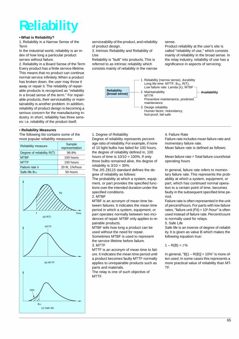
65
Reliability
• What is Reliability?
1. Reliability in a Narrow Sense of the TermIn the industrial world, reliability is an in-dex of how long a particular product serves without failure.2. Reliability in a Board Sense of the TermEvery product has a finite service lifetime. This means that no product can continue normal service infinitely. When a product has broken down, the user may throw it away or repair it. The reliability of repair-able products is recognized as "reliability in a broad sense of the term." For repair-able products, their serviceability or main-tainability is another problem. In addition, reliability of product design is becoming a serious concern for the manufacturing in-dustry. In short, reliability has three sens-es: i.e. reliability of the product itself,
serviceability of the product, and reliability of product design.3. Intrinsic Reliability and Reliability of UseReliability is "built" into products. This is referred to as intrinsic reliability which consists mainly of reliability in the narrow
sense.Product reliability at the user's site is called "reliability of use," which consists mainly of reliability in the broad sense. In the relay industry, reliability of use has a significance in aspects of servicing.
Reliability(broad sense)
1. Reliability (narrow sense), durability Long life time: MTTF, B10, R(T), Low failure rate: Lamda (λ), MTBF
2. Maintainability MTTR Preventive maintenance, predicted maintenance3. Design reliability Human factor, redundancy, fool-proof, fail-safe
Availability
• Reliability Measures
The following list contains some of the most popular reliability measures:
1. Degree of ReliabilityDegree of reliability represents percent-age ratio of reliability. For example, if none of 10 light bulbs has failed for 100 hours, the degree of reliability defined in, 100 hours of time is 10/10 = 100%. If only three bulbs remained alive, the degree of reliability is 3/10 = 30%.The JIS Z8115 standard defines the de-gree of reliability as follows:The probability at which a system, equip-ment, or part provides the specified func-tions over the intended duration under the specified conditions.2. MTBFMTBF is an acronym of mean time be-tween failures. It indicates the mean time period in which a system, equipment, or part operates normally between two inci-dences of repair. MTBF only applies to re-pairable products.MTBF tells how long a product can be used without the need for repair.Sometimes MTBF is used to represent the service lifetime before failure.3. MTTFMTTF is an acronym of mean time to fail-ure. It indicates the mean time period until a product becomes faulty MTTF normally applies to unrepairable products such as parts and materials.The relay is one of such objective of MTTF.
4. Failure RateFailure rate includes mean failure rate and momentary failure rate.Mean failure rate is defined as follows:
Mean failure rate = Total failure count/total operating hours
In general, failure rate refers to momen-tary failure rate. This represents the prob-ability at which a system, equipment, or part, which has continued normal opera-tion to a certain point of time, becomes faulty in the subsequent specified time pe-riod.Failure rate is often represented in the unit of percent/hours. For parts with low failure rates, "failure unit (Fit) = 10
9
/hour" is often used instead of failure rate. Percent/count is normally used for relays.5. Safe LifeSafe life is an inverse of degree of reliabil-ity. It is given as value B which makes the following equation true:
1 – R(B) =
t
%
In general, "B[1 – R(B)] = 10%" is more of-ten used. In some cases this represents a more practical value of reliability than MT-TF.
Reliability measure Sample representation
Degree of reliability R(T) 99.9%
MTBF 100 hours
MTTF 100 hours
Failure rate
λ
20 fit, 1%/hour
Safe life B
10
50 hours
f(t)
T Time(a) R(T)
(b) MTTF
MTTF
10%
B10
(c) Safe life
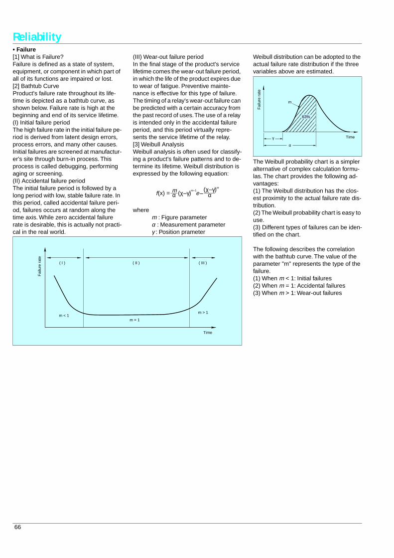
66
Reliability
• Failure
[1] What is Failure?Failure is defined as a state of system, equipment, or component in which part of all of its functions are impaired or lost.[2] Bathtub CurveProduct's failure rate throughout its life-time is depicted as a bathtub curve, as shown below. Failure rate is high at the beginning and end of its service lifetime.(I) Initial failure periodThe high failure rate in the initial failure pe-riod is derived from latent design errors, process errors, and many other causes. Initial failures are screened at manufactur-er's site through burn-in process. This process is called debugging, performing aging or screening.(II) Accidental failure periodThe initial failure period is followed by a long period with low, stable failure rate. In this period, called accidental failure peri-od, failures occurs at random along the time axis. While zero accidental failure rate is desirable, this is actually not practi-cal in the real world.
(III) Wear-out failure periodIn the final stage of the product's service lifetime comes the wear-out failure period, in which the life of the product expires due to wear of fatigue. Preventive mainte-nance is effective for this type of failure. The timing of a relay's wear-out failure can be predicted with a certain accuracy from the past record of uses. The use of a relay is intended only in the accidental failure period, and this period virtually repre-sents the service lifetime of the relay.[3] Weibull AnalysisWeibull analysis is often used for classify-ing a product's failure patterns and to de-termine its lifetime. Weibull distribution is expressed by the following equation:
where
m
: Figure parameter
α
: Measurement parameter
γ
: Position prameter
(x) = em mm
(χ–γ) (χ–γ)f α α
–1–
( I ) ( II ) ( III )
m < 1m = 1
m > 1
Fai
lure
rat
e
Time
Weibull distribution can be adopted to the actual failure rate distribution if the three variables above are estimated.
The Weibull probability chart is a simpler alternative of complex calculation formu-las. The chart provides the following ad-vantages:(1) The Weibull distribution has the clos-est proximity to the actual failure rate dis-tribution.(2) The Weibull probability chart is easy to use.(3) Different types of failures can be iden-tified on the chart.
The following describes the correlation with the bathtub curve. The value of the parameter "m" represents the type of the failure.(1) When
m
< 1: Initial failures(2) When
m
= 1: Accidental failures(3) When
m
> 1: Wear-out failures
m
63%
Fai
lure
rat
e
γ
α
Time
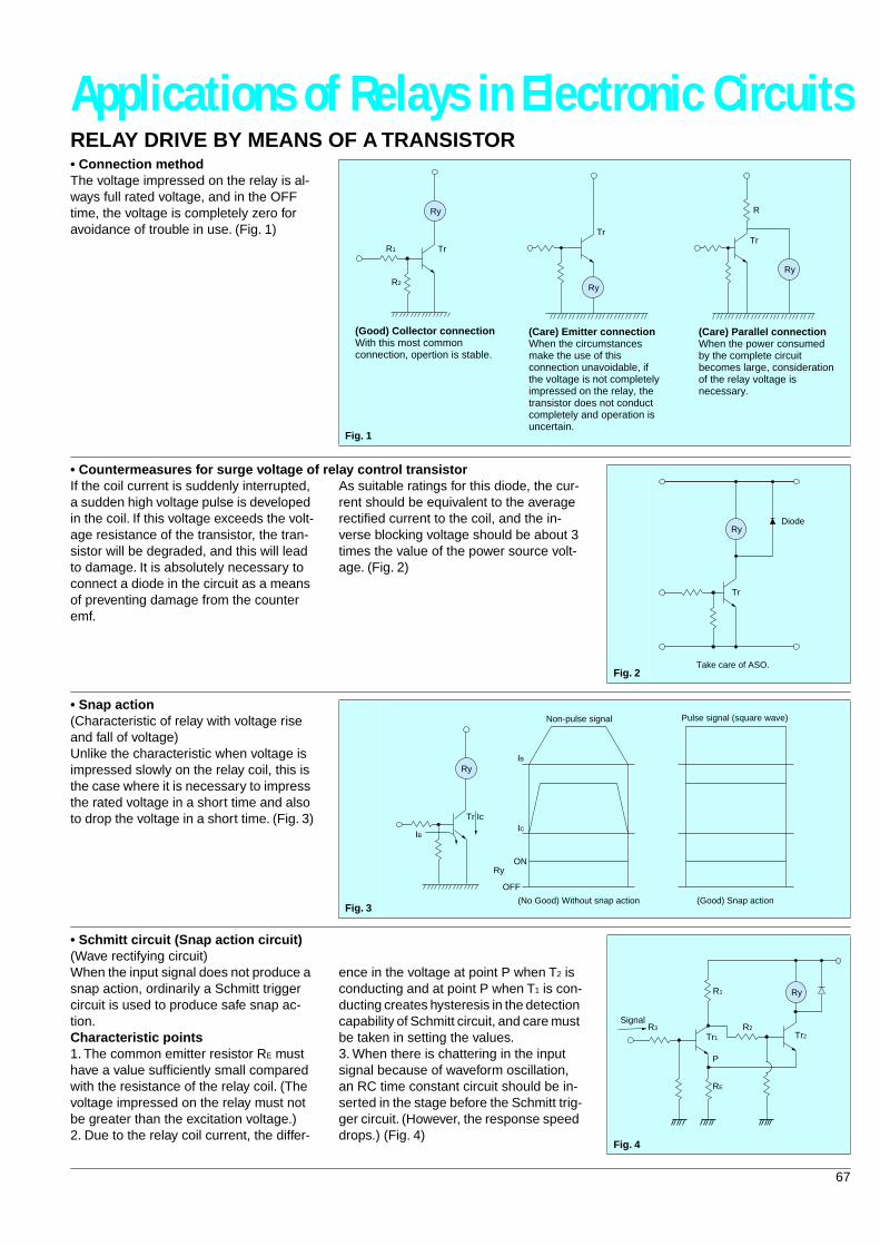
67
Applications of Relays in Electronic Circuits
RELAY DRIVE BY MEANS OF A TRANSISTOR
• Connection method
The voltage impressed on the relay is al-ways full rated voltage, and in the OFF time, the voltage is completely zero for avoidance of trouble in use. (Fig. 1)
Fig. 1
R1
R2
Tr
Ry
(Good) Collector connectionWith this most commonconnection, opertion is stable.
Tr
Ry
(Care) Emitter connectionWhen the circumstancesmake the use of thisconnection unavoidable, if the voltage is not completelyimpressed on the relay, thetransistor does not conductcompletely and operation is uncertain.
R
Tr
Ry
(Care) Parallel connectionWhen the power consumedby the complete circuitbecomes large, considerationof the relay voltage is necessary.
• Countermeasures for surge voltage of relay control transistor
If the coil current is suddenly interrupted, a sudden high voltage pulse is developed in the coil. If this voltage exceeds the volt-age resistance of the transistor, the tran-sistor will be degraded, and this will lead to damage. It is absolutely necessary to connect a diode in the circuit as a means of preventing damage from the counter emf.
As suitable ratings for this diode, the cur-rent should be equivalent to the average rectified current to the coil, and the in-verse blocking voltage should be about 3 times the value of the power source volt-age. (Fig. 2)
Fig. 2
Tr
RyDiode
Take care of ASO.
• Snap action
(Characteristic of relay with voltage rise and fall of voltage)Unlike the characteristic when voltage is impressed slowly on the relay coil, this is the case where it is necessary to impress the rated voltage in a short time and also to drop the voltage in a short time. (Fig. 3)
Fig. 3
IB
Tr Ic
Ry
ON
OFF
Ry
IB
IC
Non-pulse signal
(No Good) Without snap action
Pulse signal (square wave)
(Good) Snap action
• Schmitt circuit (Snap action circuit)
(Wave rectifying circuit)When the input signal does not produce a snap action, ordinarily a Schmitt trigger circuit is used to produce safe snap ac-tion.
Characteristic points
1. The common emitter resistor R
E
must have a value sufficiently small compared with the resistance of the relay coil. (The voltage impressed on the relay must not be greater than the excitation voltage.)2. Due to the relay coil current, the differ-
ence in the voltage at point P when T
2
is conducting and at point P when T
1
is con-ducting creates hysteresis in the detection capability of Schmitt circuit, and care must be taken in setting the values.3. When there is chattering in the input signal because of waveform oscillation, an RC time constant circuit should be in-serted in the stage before the Schmitt trig-ger circuit. (However, the response speed drops.) (Fig. 4)
Fig. 4
R2R3
R1
RE
P
Ry
Signal
Tr1 Tr2
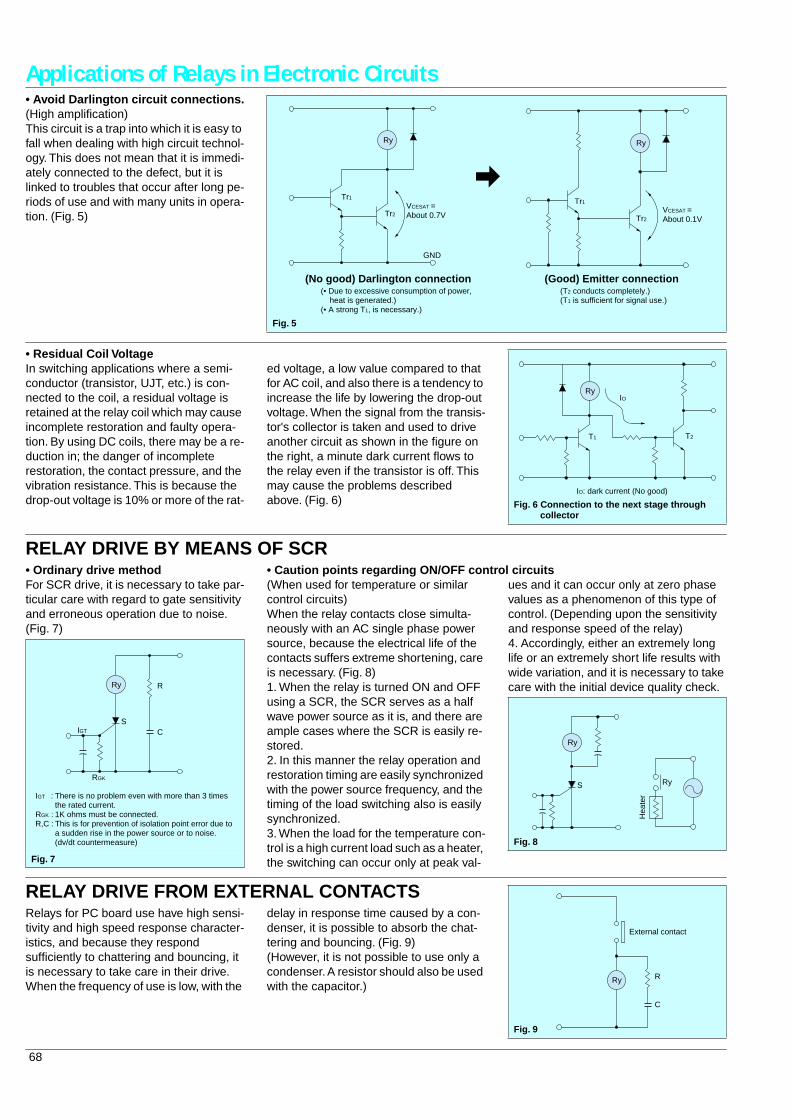
68
Applications of Relays in Electronic Circuits
• Avoid Darlington circuit connections.
(High amplification)This circuit is a trap into which it is easy to fall when dealing with high circuit technol-ogy. This does not mean that it is immedi-ately connected to the defect, but it is linked to troubles that occur after long pe-riods of use and with many units in opera-tion. (Fig. 5)
Fig. 5
VCESAT =About 0.7V
VCESAT =About 0.1V
GND
Tr1 Tr1
Tr2Tr2
Ry Ry
(No good) Darlington connection(• Due to excessive consumption of power, heat is generated.)(• A strong T1, is necessary.)
(Good) Emitter connection(T2 conducts completely.)(T1 is sufficient for signal use.)
• Residual Coil Voltage
In switching applications where a semi-conductor (transistor, UJT, etc.) is con-nected to the coil, a residual voltage is retained at the relay coil which may cause incomplete restoration and faulty opera-tion. By using DC coils, there may be a re-duction in; the danger of incomplete restoration, the contact pressure, and the vibration resistance. This is because the drop-out voltage is 10% or more of the rat-
ed voltage, a low value compared to that for AC coil, and also there is a tendency to increase the life by lowering the drop-out voltage. When the signal from the transis-tor's collector is taken and used to drive another circuit as shown in the figure on the right, a minute dark current flows to the relay even if the transistor is off. This may cause the problems described above. (Fig. 6)
Fig. 6 Connection to the next stage through collector
Ry
T2
IO
T1
IO: dark current (No good)
RELAY DRIVE BY MEANS OF SCR
• Ordinary drive method
For SCR drive, it is necessary to take par-ticular care with regard to gate sensitivity and erroneous operation due to noise. (Fig. 7)
Fig. 7
RGK
There is no problem even with more than 3 timesthe rated current.1K ohms must be connected.This is for prevention of isolation point error due toa sudden rise in the power source or to noise.(dv/dt countermeasure)
IGT C
R
S
Ry
IGT :
RGK : R,C :
• Caution points regarding ON/OFF control circuits
(When used for temperature or similar control circuits)When the relay contacts close simulta-neously with an AC single phase power source, because the electrical life of the contacts suffers extreme shortening, care is necessary. (Fig. 8)1. When the relay is turned ON and OFF using a SCR, the SCR serves as a half wave power source as it is, and there are ample cases where the SCR is easily re-stored.2. In this manner the relay operation and restoration timing are easily synchronized with the power source frequency, and the timing of the load switching also is easily synchronized.3. When the load for the temperature con-trol is a high current load such as a heater, the switching can occur only at peak val-
ues and it can occur only at zero phase values as a phenomenon of this type of control. (Depending upon the sensitivity and response speed of the relay)4. Accordingly, either an extremely long life or an extremely short life results with wide variation, and it is necessary to take care with the initial device quality check.
Fig. 8
S
Ry
Ry
Hea
ter
RELAY DRIVE FROM EXTERNAL CONTACTS
Relays for PC board use have high sensi-tivity and high speed response character-istics, and because they respond sufficiently to chattering and bouncing, it is necessary to take care in their drive.When the frequency of use is low, with the
delay in response time caused by a con-denser, it is possible to absorb the chat-tering and bouncing. (Fig. 9)(However, it is not possible to use only a condenser. A resistor should also be used with the capacitor.)
Fig. 9
Ry R
C
External contact
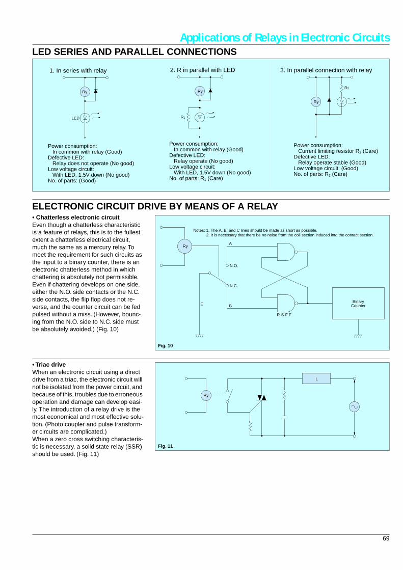
69
Applications of Relays in Electronic Circuits
LED SERIES AND PARALLEL CONNECTIONS
Ry
LED
Power consumption: In common with relay (Good)Defective LED: Relay does not operate (No good)Low voltage circuit: With LED, 1.5V down (No good)No. of parts: (Good)
1. In series with relay
R1
Ry
Power consumption: In common with relay (Good)Defective LED: Relay operate (No good)Low voltage circuit: With LED, 1.5V down (No good)No. of parts: R1 (Care)
2. R in parallel with LED
Ry
R2
Power consumption: Current limiting resistor R2 (Care)Defective LED: Relay operate stable (Good)Low voltage circuit: (Good)No. of parts: R2 (Care)
3. In parallel connection with relay
ELECTRONIC CIRCUIT DRIVE BY MEANS OF A RELAY
• Chatterless electronic circuit
Even though a chatterless characteristic is a feature of relays, this is to the fullest extent a chatterless electrical circuit, much the same as a mercury relay. To meet the requirement for such circuits as the input to a binary counter, there is an electronic chatterless method in which chattering is absolutely not permissible. Even if chattering develops on one side, either the N.O. side contacts or the N.C. side contacts, the flip flop does not re-verse, and the counter circuit can be fed pulsed without a miss. (However, bounc-ing from the N.O. side to N.C. side must be absolutely avoided.) (Fig. 10)
Fig. 10
N.O.
N.C.
R-S-F.F
BinaryCounterB
A
C
Ry
Notes: 1. The A, B, and C lines should be made as short as possible. 2. It is necessary that there be no noise from the coil section induced into the contact section.
• Triac drive
When an electronic circuit using a direct drive from a triac, the electronic circuit will not be isolated from the power circuit, and because of this, troubles due to erroneous operation and damage can develop easi-ly. The introduction of a relay drive is the most economical and most effective solu-tion. (Photo coupler and pulse transform-er circuits are complicated.)When a zero cross switching characteris-tic is necessary, a solid state relay (SSR) should be used. (Fig. 11)
Fig. 11
Ry
L
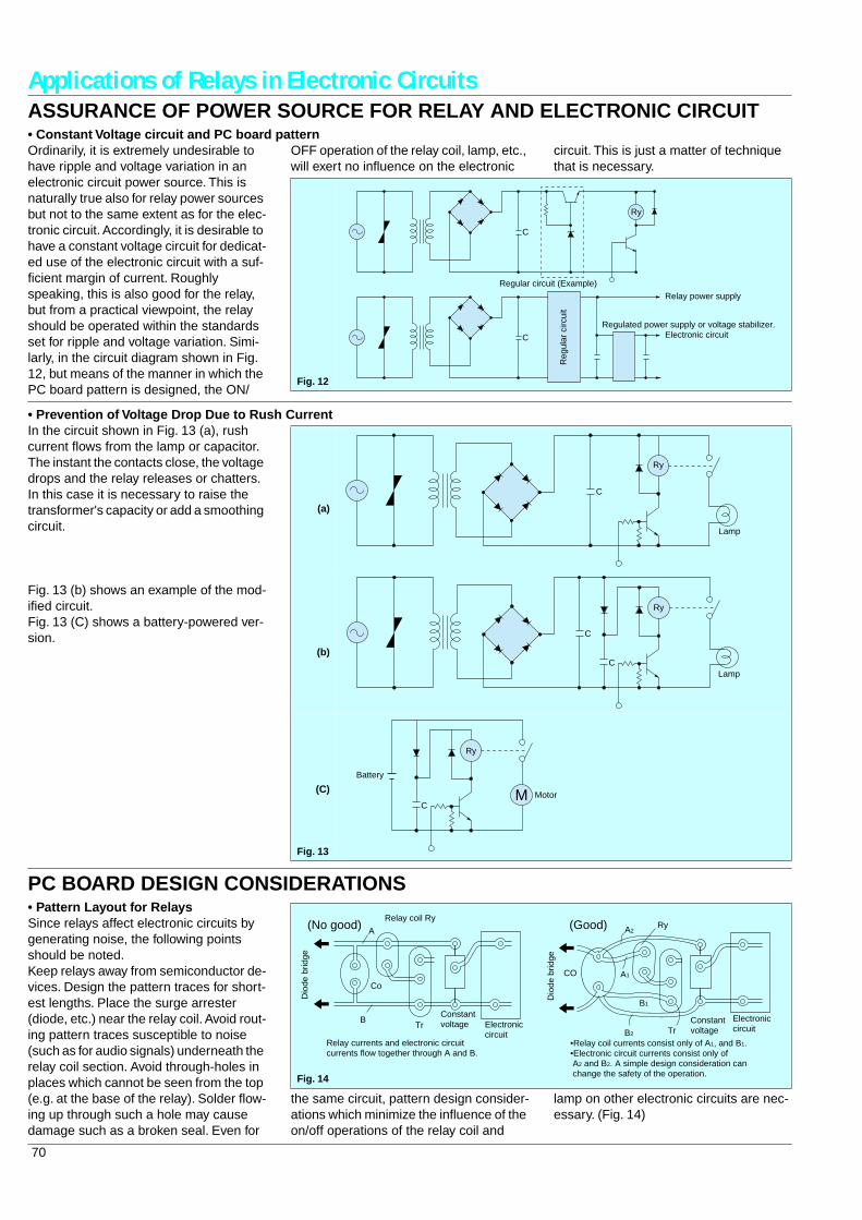
70
Applications of Relays in Electronic Circuits
ASSURANCE OF POWER SOURCE FOR RELAY AND ELECTRONIC CIRCUIT
• Constant Voltage circuit and PC board pattern
Ordinarily, it is extremely undesirable to have ripple and voltage variation in an electronic circuit power source. This is naturally true also for relay power sources but not to the same extent as for the elec-tronic circuit. Accordingly, it is desirable to have a constant voltage circuit for dedicat-ed use of the electronic circuit with a suf-ficient margin of current. Roughly speaking, this is also good for the relay, but from a practical viewpoint, the relay should be operated within the standards set for ripple and voltage variation. Simi-larly, in the circuit diagram shown in Fig. 12, but means of the manner in which the PC board pattern is designed, the ON/
OFF operation of the relay coil, lamp, etc., will exert no influence on the electronic
circuit. This is just a matter of technique that is necessary.
Fig. 12
C
Ry
C
Regular circuit (Example)
Reg
ular
circ
uit
Relay power supply
Electronic circuitRegulated power supply or voltage stabilizer.
• Prevention of Voltage Drop Due to Rush Current
In the circuit shown in Fig. 13 (a), rush current flows from the lamp or capacitor. The instant the contacts close, the voltage drops and the relay releases or chatters.In this case it is necessary to raise the transformer's capacity or add a smoothing circuit.
Fig. 13 (b) shows an example of the mod-ified circuit. Fig. 13 (C) shows a battery-powered ver-sion.
(a)
(b)
(C)
Fig. 13
C
Ry
Lamp
C
C
Ry
Lamp
C
Ry
M Motor
Battery
PC BOARD DESIGN CONSIDERATIONS
• Pattern Layout for Relays
Since relays affect electronic circuits by generating noise, the following points should be noted.Keep relays away from semiconductor de-vices. Design the pattern traces for short-est lengths. Place the surge arrester (diode, etc.) near the relay coil. Avoid rout-ing pattern traces susceptible to noise (such as for audio signals) underneath the relay coil section. Avoid through-holes in places which cannot be seen from the top (e.g. at the base of the relay). Solder flow-ing up through such a hole may cause damage such as a broken seal. Even for
the same circuit, pattern design consider-ations which minimize the influence of the on/off operations of the relay coil and
lamp on other electronic circuits are nec-essary. (Fig. 14)
A
B
Co
TrConstantvoltage Electronic
circuit
Relay coil Ry(No good)
Dio
de b
ridge
Relay currents and electronic circuitcurrents flow together through A and B.
B2
B1
A1
A2
CO
Ry
TrConstantvoltage
Electroniccircuit
Dio
de b
ridge
(Good)
•Relay coil currents consist only of A1, and B1.•Electronic circuit currents consist only of A2 and B2. A simple design consideration can change the safety of the operation.Fig. 14
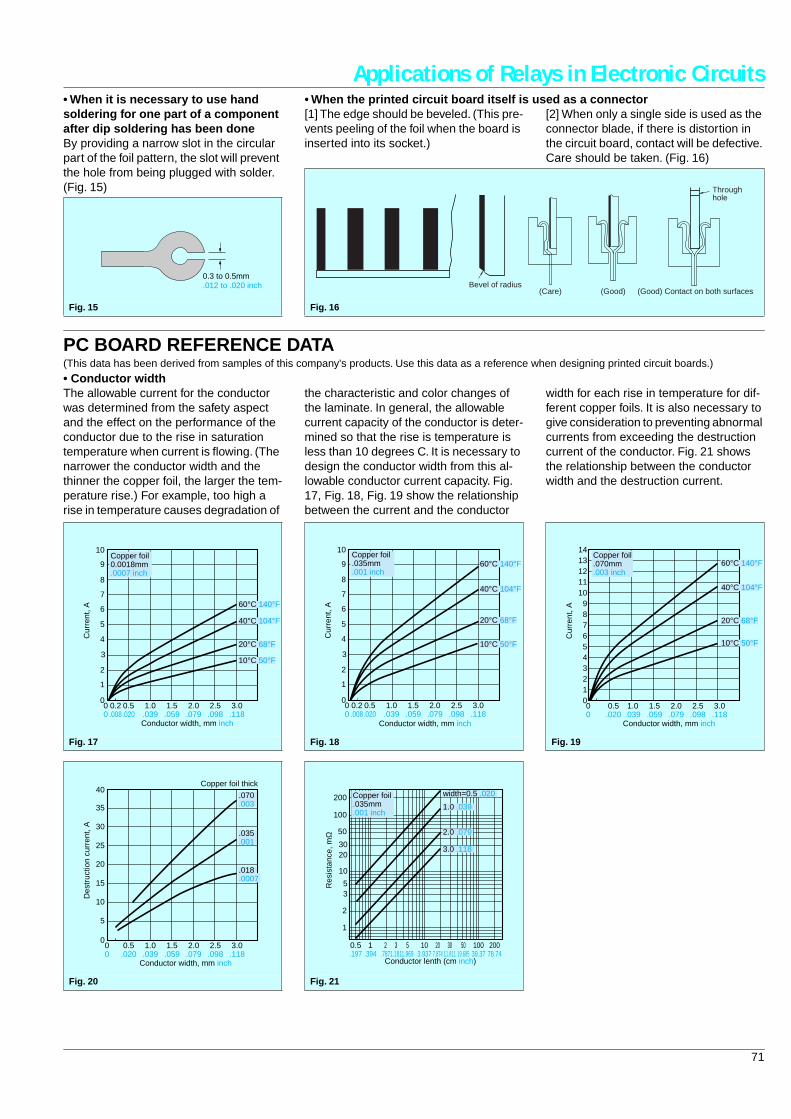
71
Applications of Relays in Electronic Circuits
• When it is necessary to use hand soldering for one part of a component after dip soldering has been done
By providing a narrow slot in the circular part of the foil pattern, the slot will prevent the hole from being plugged with solder. (Fig. 15)
Fig. 15
0.3 to 0.5mm.012 to .020 inch
• When the printed circuit board itself is used as a connector
[1] The edge should be beveled. (This pre-vents peeling of the foil when the board is inserted into its socket.)
[2] When only a single side is used as the connector blade, if there is distortion in the circuit board, contact will be defective. Care should be taken. (Fig. 16)
Fig. 16
Bevel of radius(Care) (Good) (Good) Contact on both surfaces
Throughhole
PC BOARD REFERENCE DATA
(This data has been derived from samples of this company's products. Use this data as a reference when designing printed circuit boards.)
• Conductor width
The allowable current for the conductor was determined from the safety aspect and the effect on the performance of the conductor due to the rise in saturation temperature when current is flowing. (The narrower the conductor width and the thinner the copper foil, the larger the tem-perature rise.) For example, too high a rise in temperature causes degradation of
the characteristic and color changes of the laminate. In general, the allowable current capacity of the conductor is deter-mined so that the rise is temperature is less than 10 degrees C. It is necessary to design the conductor width from this al-lowable conductor current capacity. Fig. 17, Fig. 18, Fig. 19 show the relationship between the current and the conductor
width for each rise in temperature for dif-ferent copper foils. It is also necessary to give consideration to preventing abnormal currents from exceeding the destruction current of the conductor. Fig. 21 shows the relationship between the conductor width and the destruction current.
Fig. 17
3.0.118
2.5.098
2.0.079
1.5.059
1.0.039
0.5.020
00
0
1
2
3
Cur
rent
, A
4
5
6
7
8
9
10
0.2.008
60°C 140°F
Conductor width, mm inch
Copper foil0.0018mm.0007 inch
10°C 50°F
20°C 68°F
40°C 104°F
Fig. 18
3.0.118
2.5.098
2.0.079
1.5.059
1.0.039
0.5.020
00
0
1
2
3
Cur
rent
, A
4
5
6
7
8
9
10
0.2.008
60°C 140°F
Conductor width, mm inch
Copper foil.035mm.001 inch
10°C 50°F
20°C 68°F
40°C 104°F
Fig. 19
Copper foil.070mm.003 inch
3.0.118
2.5.098
2.0.079
1.5.059
1.0.039
0.5.020
00
0123456789
1011121314
Cur
rent
, A60°C 140°F
Conductor width, mm inch
10°C 50°F
20°C 68°F
40°C 104°F
Fig. 20
3.0.118
2.5.098
2.0.079
1.5.059
1.0.039
0.5.020
00
0
5
10
15
20
25
30
35
40
Des
truc
tion
curr
ent,
A
.070
.003
.035
.001
.018
.0007
Conductor width, mm inch
Copper foil thick
Fig. 21
20078.74
10039.37
5019.685
3011.811
207.874
103.937
51.969
31.181
2.787
1.394
1
2
5
10
2030
3
50
100
200
0.5.197
Res
ista
nce,
mΩ
width=0.5 .020
1.0 .039
Conductor lenth (cm inch)
3.0 .118
2.0 .079
Copper foil.035mm.001 inch
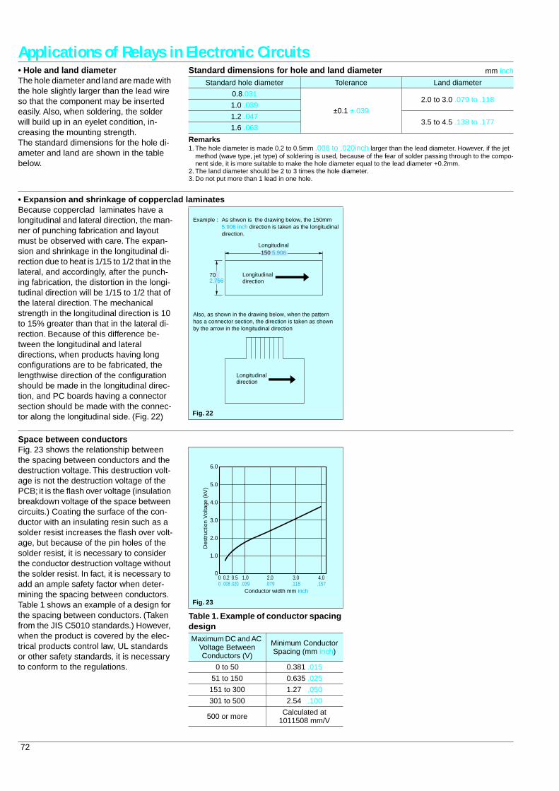
72
Applications of Relays in Electronic Circuits
• Hole and land diameter
The hole diameter and land are made with the hole slightly larger than the lead wire so that the component may be inserted easily. Also, when soldering, the solder will build up in an eyelet condition, in-creasing the mounting strength.The standard dimensions for the hole di-ameter and land are shown in the table below.
Standard dimensions for hole and land diameter
mm inch
Remarks
1. The hole diameter is made 0.2 to 0.5mm
.008 to .020inch
larger than the lead diameter. However, if the jet method (wave type, jet type) of soldering is used, because of the fear of solder passing through to the compo-nent side, it is more suitable to make the hole diameter equal to the lead diameter +0.2mm.
2. The land diameter should be 2 to 3 times the hole diameter.3. Do not put more than 1 lead in one hole.
Standard hole diameter Tolerance Land diameter
0.8.031
±
0.1
±
.039
2.0 to 3.0 .079 to .1181.0 .039
1.2 .0473.5 to 4.5 .138 to .177
1.6 .063
• Expansion and shrinkage of copperclad laminates
Because copperclad laminates have a longitudinal and lateral direction, the man-ner of punching fabrication and layout must be observed with care. The expan-sion and shrinkage in the longitudinal di-rection due to heat is 1/15 to 1/2 that in the lateral, and accordingly, after the punch-ing fabrication, the distortion in the longi-tudinal direction will be 1/15 to 1/2 that of the lateral direction. The mechanical strength in the longitudinal direction is 10 to 15% greater than that in the lateral di-rection. Because of this difference be-tween the longitudinal and lateral directions, when products having long configurations are to be fabricated, the lengthwise direction of the configuration should be made in the longitudinal direc-tion, and PC boards having a connector section should be made with the connec-tor along the longitudinal side. (Fig. 22)
Fig. 22
Longitudinal150 5.906
702.756
Longitudinaldirection
As shwon is the drawing below, the 150mm5.906 inch direction is taken as the longitudinaldirection.
Example :
Longitudinaldirection
Also, as shown in the drawing below, when the patternhas a connector section, the direction is taken as shownby the arrow in the longitudinal direction
Space between conductors
Fig. 23 shows the relationship between the spacing between conductors and the destruction voltage. This destruction volt-age is not the destruction voltage of the PCB; it is the flash over voltage (insulation breakdown voltage of the space between circuits.) Coating the surface of the con-ductor with an insulating resin such as a solder resist increases the flash over volt-age, but because of the pin holes of the solder resist, it is necessary to consider the conductor destruction voltage without the solder resist. In fact, it is necessary to add an ample safety factor when deter-mining the spacing between conductors. Table 1 shows an example of a design for the spacing between conductors. (Taken from the JIS C5010 standards.) However, when the product is covered by the elec-trical products control law, UL standards or other safety standards, it is necessary to conform to the regulations.
Table 1. Example of conductor spacing design
Fig. 23
Maximum DC and AC Voltage Between Conductors (V)
Minimum Conductor Spacing (mm inch)
0 to 50 0.381 .015
51 to 150 0.635 .025
151 to 300 1.27 .050
301 to 500 2.54 .100
500 or more Calculated at 1011508 mm/V
6.0
5.0
4.0
3.0
2.0
1.0
000
0.2.008
0.5.020
1.0.039
2.0.079
3.0.118
4.0.157
Des
truc
tion
Vol
tage
(kV
)
Conductor width mm inch
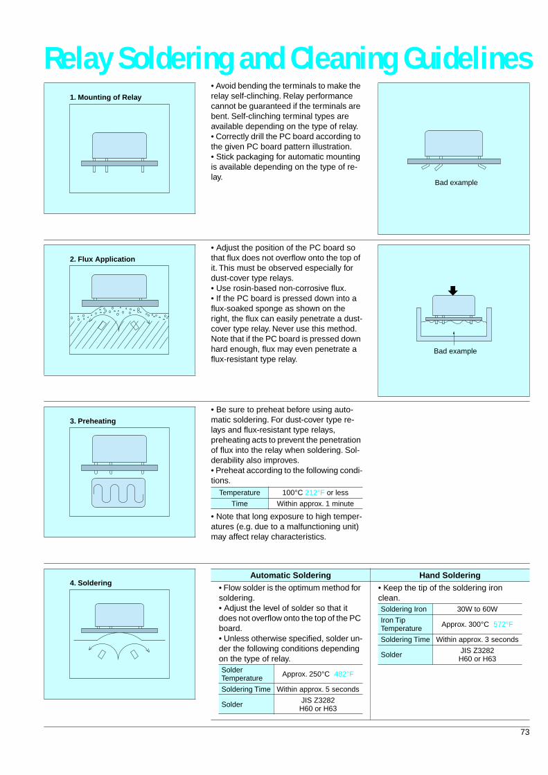
73
Relay Soldering and Cleaning Guidelines
• Avoid bending the terminals to make the relay self-clinching. Relay performance cannot be guaranteed if the terminals are bent. Self-clinching terminal types are available depending on the type of relay.• Correctly drill the PC board according to the given PC board pattern illustration.• Stick packaging for automatic mounting is available depending on the type of re-lay.
1. Mounting of Relay
Bad example
• Adjust the position of the PC board so that flux does not overflow onto the top of it. This must be observed especially for dust-cover type relays.• Use rosin-based non-corrosive flux.• If the PC board is pressed down into a flux-soaked sponge as shown on the right, the flux can easily penetrate a dust-cover type relay. Never use this method. Note that if the PC board is pressed down hard enough, flux may even penetrate a flux-resistant type relay.
2. Flux Application
Bad example
• Be sure to preheat before using auto-matic soldering. For dust-cover type re-lays and flux-resistant type relays, preheating acts to prevent the penetration of flux into the relay when soldering. Sol-derability also improves.• Preheat according to the following condi-tions.
• Note that long exposure to high temper-atures (e.g. due to a malfunctioning unit) may affect relay characteristics.
3. Preheating
Temperature 100
°
C 212
°
F or less
Time Within approx. 1 minute
4. Soldering
Automatic Soldering Hand Soldering
• Flow solder is the optimum method for soldering.• Adjust the level of solder so that it does not overflow onto the top of the PC board.• Unless otherwise specified, solder un-der the following conditions depending on the type of relay.
• Keep the tip of the soldering iron clean.
Solder Temperature Approx. 250
°
C 482°F
Soldering Time Within approx. 5 seconds
Solder JIS Z3282H60 or H63
Soldering Iron 30W to 60W
Iron Tip Temperature Approx. 300°C 572°F
Soldering Time Within approx. 3 seconds
Solder JIS Z3282H60 or H63
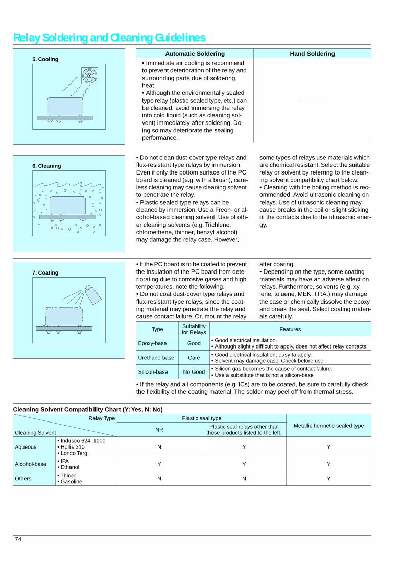
74
Relay Soldering and Cleaning Guidelines
5. CoolingAutomatic Soldering Hand Soldering
• Immediate air cooling is recommend to prevent deterioration of the relay and surrounding parts due of soldering heat.• Although the environmentally sealed type relay (plastic sealed type, etc.) can be cleaned, avoid immersing the relay into cold liquid (such as cleaning sol-vent) immediately after soldering. Do-ing so may deteriorate the sealing performance.
—
6. Cleaning
• Do not clean dust-cover type relays and flux-resistant type relays by immersion. Even if only the bottom surface of the PC board is cleaned (e.g. with a brush), care-less cleaning may cause cleaning solvent to penetrate the relay.• Plastic sealed type relays can be cleaned by immersion. Use a Freon- or al-cohol-based cleaning solvent. Use of oth-er cleaning solvents (e.g. Trichlene, chloroethene, thinner, benzyl alcohol) may damage the relay case. However,
some types of relays use materials which are chemical resistant. Select the suitable relay or solvent by referring to the clean-ing solvent compatibility chart below.• Cleaning with the boiling method is rec-ommended. Avoid ultrasonic cleaning on relays. Use of ultrasonic cleaning may cause breaks in the coil or slight sticking of the contacts due to the ultrasonic ener-gy.
7. Coating
• If the PC board is to be coated to prevent the insulation of the PC board from dete-riorating due to corrosive gases and high temperatures, note the following.• Do not coat dust-cover type relays and flux-resistant type relays, since the coat-ing material may penetrate the relay and cause contact failure. Or, mount the relay
after coating.• Depending on the type, some coating materials may have an adverse affect on relays. Furthermore, solvents (e.g. xy-lene, toluene, MEK, I.P.A.) may damage the case or chemically dissolve the epoxy and break the seal. Select coating materi-als carefully.
• If the relay and all components (e.g. ICs) are to be coated, be sure to carefully check the flexibility of the coating material. The solder may peel off from thermal stress.
Type Suitability for Relays Features
Epoxy-base Good • Good electrical insulation.• Although slightly difficult to apply, does not affect relay contacts.
Urethane-base Care • Good electrical insulation, easy to apply.• Solvent may damage case. Check before use.
Silicon-base No Good • Silicon gas becomes the cause of contact failure.• Use a substitute that is not a silicon-base
Cleaning Solvent Compatibility Chart (Y: Yes, N: No)Relay Type Plastic seal type
Metallic hermetic sealed typeCleaning Solvent NR Plastic seal relays other than
those products listed to the left.
Aqueous• Indusco 624, 1000• Hollis 310• Lonco Terg
N Y Y
Alcohol-base • IPA• Ethanol Y Y Y
Others • Thiner• Gasoline N N Y

75
SMT Soldering GuidelinesCAUTIONS FOR SURFACE MOUNT RELAY INSTALLATIONTo meet the market demand for downsiz-ing to smaller, lighter, and thinner prod-ucts, PC boards also need to proceed from Insertion mounting to surface mount-
ing technology. To meet this need, we of-fer a line of surface mount relays. The following describes some cautions re-quired for surface mount relay installation
to prevent malfunction and incorrect oper-ation.
• What is a Surface Mount Relay?1. From IMT to SMTConventional insertion mount technology (IMT) with some 30 years of history is now being replaced with surface mount tech-nology (SMT).Solid-state components such as resistors, ICs, and diodes can withstand high heat stresses from reflow soldering because they use no mechanical parts. In contrast, the conventional electro-mechanical re-lays consisting of solenoid coils, springs, and armatures are very sensitive to ther-mal stress from reflow soldering.
We applied the experience gained from our advanced relay technologies to pro-duce high-performance electromagnetic
relays compatible with surface mount technologies such as IRS and VPS.
• Insertion Mount Technology vs. Surface Mount Technology
Insertion Mounting Technology: IMT
Components' leads are inserted into lead holes of PC board and are soldered to copper pads on the other side of the board using flow-soldering techniques.
Surface Mount Technology (SMT)
Components are placed on copper pads precoated with paste solder and the board assembly is heated to solder the compo-nents on the pads (reflow soldering).
ResistorRelay
PC board
Relay
PC board IC
Chip resistance
2. Features and Effects
The surface mount relay is manufactured with the following advanced technologies:• Heat-resistance encapsulation tech-
nique• Gas analysis• Reliability assessment• Precision molding technique for heat-re-
sistant materials
Features Effects
• Allows high density mounting• Components can be installed on both sides of a board• Ceramic PC boards can be used
System downsizing
• Compatible with automatic placement by robots• Drilling for lead holes is not required• Compact system designs are possible due to high density mounting
Overall cost reduction
• High heat resistance• Anti-gas measures
High reliability
• TQ-SMD Relay
Case
Armature block
Body block
Low volatility gas liquid crystal resin case
High impact resistant flexible hinge spring
Coil sealed formation body(High heat resistance, high insulation, low volatility gas)
Permanent magnet, laser welding connection of iron core.
Warped cross-section iron core- EIAJ standard conformant- High wthstand voltage between contacts
3. Examples of SMT ApplicationsThe following describes some examples of typical SMT applications:(1) Infrared Reflow Soldering (IRS)IRS is the most popular reflow soldering technology now available for surface mounting. It uses a sheath heater or infra-red lamp as its heat source. PC board as-semblies are continuously soldered as they are transferred through a tunnel fur-nace comprised of a preheating, heating, and cooling-stages.
(2) Vapor Phase Soldering (VPS)With VPS technology, PCB assemblies are carried through a special inactive sol-vent, such as Fluorinert FC-70, that has been heated to a vapor state. As the sat-urated vapor condenses on the PC board surface, the resulting evaporation heat provides the energy for reflow soldering.
(3) Belt conveyer reflow furnaceAs PCB assemblies are transferred on a thin, heat-resistant belt conveyer, they are soldered by the heat from hotplates placed begeath the conveyer belt.(4) Double Wave Soldering (DWS)Components are glued to the PC board surface. The board assembly is trans-ferred through a molten solder fountain (with the component side facing down), and the components are soldered to the board.(5) Other TechnologiesOther reflow soldering technologies include those utilizing lasers, hot air, and pulse heaters.
Preheatstage
Heatingstage
Coolingstage
Cooling coil
Saturated vapor
Heater
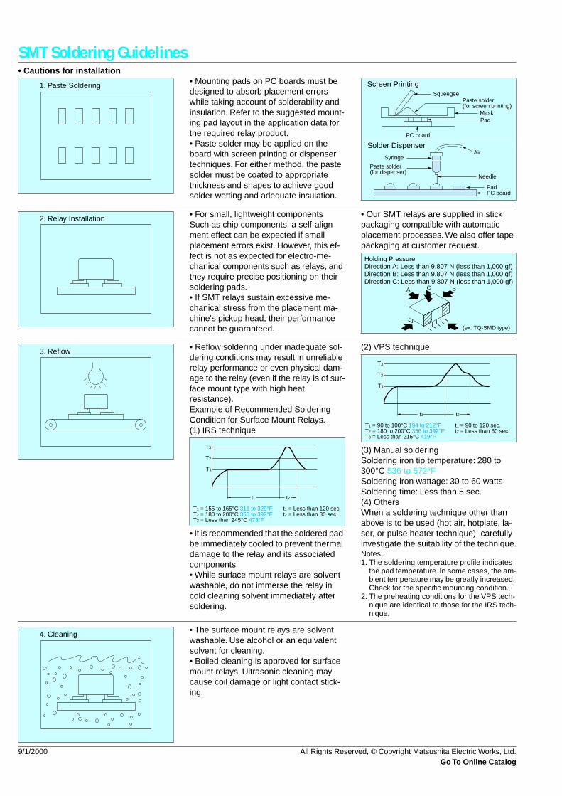
76
SMT Soldering Guidelines
• Cautions for installation
• Mounting pads on PC boards must be designed to absorb placement errors while taking account of solderability and insulation. Refer to the suggested mount-ing pad layout in the application data for the required relay product.• Paste solder may be applied on the board with screen printing or dispenser techniques. For either method, the paste solder must be coated to appropriate thickness and shapes to achieve good solder wetting and adequate insulation.
1. Paste SolderingSqueegee
Paste solder(for screen printing)
MaskPad
PC board
Screen Printing
Solder Dispenser
Syringe
Paste solder(for dispenser)
Air
Needle
PadPC board
• For small, lightweight componentsSuch as chip components, a self-align-ment effect can be expected if small placement errors exist. However, this ef-fect is not as expected for electro-me-chanical components such as relays, and they require precise positioning on their soldering pads.• If SMT relays sustain excessive me-chanical stress from the placement ma-chine's pickup head, their performance cannot be guaranteed.
• Our SMT relays are supplied in stick packaging compatible with automatic placement processes. We also offer tape packaging at customer request.
2. Relay Installation
A
(ex. TQ-SMD type)
C B
Holding PressureDirection A: Less than 9.807 N (less than 1,000 gf)Direction B: Less than 9.807 N (less than 1,000 gf)Direction C: Less than 9.807 N (less than 1,000 gf)
• Reflow soldering under inadequate sol-dering conditions may result in unreliable relay performance or even physical dam-age to the relay (even if the relay is of sur-face mount type with high heat resistance).Example of Recommended Soldering Condition for Surface Mount Relays.(1) IRS technique
• It is recommended that the soldered pad be immediately cooled to prevent thermal damage to the relay and its associated components.• While surface mount relays are solvent washable, do not immerse the relay in cold cleaning solvent immediately after soldering.
(2) VPS technique
(3) Manual solderingSoldering iron tip temperature: 280 to 300
°
C 536 to 572
°
FSoldering iron wattage: 30 to 60 wattsSoldering time: Less than 5 sec.(4) OthersWhen a soldering technique other than above is to be used (hot air, hotplate, la-ser, or pulse heater technique), carefully investigate the suitability of the technique.
Notes:1. The soldering temperature profile indicates
the pad temperature. In some cases, the am-bient temperature may be greatly increased. Check for the specific mounting condition.
2. The preheating conditions for the VPS tech-nique are identical to those for the IRS tech-nique.
3. Reflow
t1 t2
T3
T2
T1
T1 = 155 to 165°C 311 to 329°FT2 = 180 to 200°C 356 to 392°FT3 = Less than 245°C 473°F
t1 = Less than 120 sec.t2 = Less than 30 sec.
t1 t2
T3
T2
T1
T1 = 90 to 100°C 194 to 212°FT2 = 180 to 200°C 356 to 392°FT3 = Less than 215°C 419°F
t1 = 90 to 120 sec.t2 = Less than 60 sec.
• The surface mount relays are solvent washable. Use alcohol or an equivalent solvent for cleaning.• Boiled cleaning is approved for surface mount relays. Ultrasonic cleaning may cause coil damage or light contact stick-ing.
4. Cleaning
9/1/2000 All Rights Reserved, © Copyright Matsushita Electric Works, Ltd.
Go To Online Catalog